EP2706551A2 - Electric magnet device and switch provided therewith - Google Patents
Electric magnet device and switch provided therewith Download PDFInfo
- Publication number
- EP2706551A2 EP2706551A2 EP20130178744 EP13178744A EP2706551A2 EP 2706551 A2 EP2706551 A2 EP 2706551A2 EP 20130178744 EP20130178744 EP 20130178744 EP 13178744 A EP13178744 A EP 13178744A EP 2706551 A2 EP2706551 A2 EP 2706551A2
- Authority
- EP
- European Patent Office
- Prior art keywords
- armature
- yoke
- electric magnet
- magnet device
- coil
- Prior art date
- Legal status (The legal status is an assumption and is not a legal conclusion. Google has not performed a legal analysis and makes no representation as to the accuracy of the status listed.)
- Granted
Links
- 230000010355 oscillation Effects 0.000 claims abstract description 19
- 230000007257 malfunction Effects 0.000 abstract description 4
- 230000007246 mechanism Effects 0.000 description 23
- 230000008878 coupling Effects 0.000 description 9
- 238000010168 coupling process Methods 0.000 description 9
- 238000005859 coupling reaction Methods 0.000 description 9
- 238000004804 winding Methods 0.000 description 7
- 230000014759 maintenance of location Effects 0.000 description 5
- 238000012986 modification Methods 0.000 description 4
- 230000004048 modification Effects 0.000 description 4
- 230000000717 retained effect Effects 0.000 description 4
- 230000000694 effects Effects 0.000 description 3
- 238000005299 abrasion Methods 0.000 description 2
- 230000015556 catabolic process Effects 0.000 description 2
- 230000007423 decrease Effects 0.000 description 2
- 238000006731 degradation reaction Methods 0.000 description 2
- 238000010586 diagram Methods 0.000 description 2
- 238000003780 insertion Methods 0.000 description 2
- 230000037431 insertion Effects 0.000 description 2
- 238000000034 method Methods 0.000 description 2
- 230000004907 flux Effects 0.000 description 1
- 239000000696 magnetic material Substances 0.000 description 1
- 230000002093 peripheral effect Effects 0.000 description 1
- 230000008569 process Effects 0.000 description 1
Images




Classifications
-
- H—ELECTRICITY
- H01—ELECTRIC ELEMENTS
- H01H—ELECTRIC SWITCHES; RELAYS; SELECTORS; EMERGENCY PROTECTIVE DEVICES
- H01H3/00—Mechanisms for operating contacts
- H01H3/22—Power arrangements internal to the switch for operating the driving mechanism
- H01H3/28—Power arrangements internal to the switch for operating the driving mechanism using electromagnet
-
- H—ELECTRICITY
- H01—ELECTRIC ELEMENTS
- H01H—ELECTRIC SWITCHES; RELAYS; SELECTORS; EMERGENCY PROTECTIVE DEVICES
- H01H50/00—Details of electromagnetic relays
- H01H50/02—Bases; Casings; Covers
- H01H50/04—Mounting complete relay or separate parts of relay on a base or inside a case
- H01H50/041—Details concerning assembly of relays
- H01H50/042—Different parts are assembled by insertion without extra mounting facilities like screws, in an isolated mounting part, e.g. stack mounting on a coil-support
-
- H—ELECTRICITY
- H01—ELECTRIC ELEMENTS
- H01H—ELECTRIC SWITCHES; RELAYS; SELECTORS; EMERGENCY PROTECTIVE DEVICES
- H01H50/00—Details of electromagnetic relays
- H01H50/16—Magnetic circuit arrangements
- H01H50/163—Details concerning air-gaps, e.g. anti-remanence, damping, anti-corrosion
-
- H—ELECTRICITY
- H01—ELECTRIC ELEMENTS
- H01H—ELECTRIC SWITCHES; RELAYS; SELECTORS; EMERGENCY PROTECTIVE DEVICES
- H01H50/00—Details of electromagnetic relays
- H01H50/16—Magnetic circuit arrangements
- H01H50/18—Movable parts of magnetic circuits, e.g. armature
- H01H50/20—Movable parts of magnetic circuits, e.g. armature movable inside coil and substantially lengthwise with respect to axis thereof; movable coaxially with respect to coil
- H01H50/22—Movable parts of magnetic circuits, e.g. armature movable inside coil and substantially lengthwise with respect to axis thereof; movable coaxially with respect to coil wherein the magnetic circuit is substantially closed
-
- H—ELECTRICITY
- H01—ELECTRIC ELEMENTS
- H01H—ELECTRIC SWITCHES; RELAYS; SELECTORS; EMERGENCY PROTECTIVE DEVICES
- H01H50/00—Details of electromagnetic relays
- H01H50/16—Magnetic circuit arrangements
- H01H50/18—Movable parts of magnetic circuits, e.g. armature
- H01H50/30—Mechanical arrangements for preventing or damping vibration or shock, e.g. by balancing of armature
-
- H—ELECTRICITY
- H01—ELECTRIC ELEMENTS
- H01H—ELECTRIC SWITCHES; RELAYS; SELECTORS; EMERGENCY PROTECTIVE DEVICES
- H01H51/00—Electromagnetic relays
- H01H51/01—Relays in which the armature is maintained in one position by a permanent magnet and freed by energisation of a coil producing an opposing magnetic field
Definitions
- the present invention relates to an electric magnet device, particularly to an electric magnet device that is used in a reset-function equipped switch used for a copying machine and the like.
- a conventional electric magnet device for example, Japanese Unexamined Patent Publication No. 2001-135521 discloses an electric magnet device in which a distance between centers of a pair of leg parts formed in an armature is made less than a distance between centers of bobbin holes.
- the electric magnet device has a structure in which the leg parts abut on an inside surface of the bobbin holes, such that an external force is applied from a predetermined direction to move the armature in the predetermined direction.
- the armature turns about an end portion of the inside surface with a small turning angle. Therefore, the armature hardly drops off from the yoke to improve an impact resistance.
- the present invention has been devised to solve the problem described above, and an object thereof is to provide an electric magnet device, in which a smooth movement of the armature inside the bobbin is ensured and, even if a vibration or an impact is applied, an attraction state between the yoke and the armature is maintained to prevent a malfunction, and a switch provided with the electric magnet device.
- an electric magnet device in order to solve the problem described above, includes: a coil adapted to insert through at least one of an armature and a yoke so as to attract surfaces of the yoke and the armature which are opposed to each other, to receive a voltage, to excite for separating the surfaces of the yoke and the armature; the armature disposed on one end side of the coil; and the yoke disposed on the other end side of the coil and adapted to oscillate, wherein an oscillation angle of the yoke is greater than an oscillation angle of the armature.
- the yoke and the armature come into surface contact with each other, a magnetic resistance decreases, and the yoke and the armature can be attracted to each other with a large attractive force. Therefore, the smooth movement of the armature is ensured and, even if the vibration or the impact is applied, the attraction state between the yoke and the armature can be maintained to prevent the malfunction.
- a ratio of the oscillation angle of the yoke to the oscillation angle of the armature may be greater than 1:1 and less than or equal to 3:1.
- the ratio of the oscillation angles of the yoke to the armature is less than or equal to 1:1, that is for example, 1:0.5, the yoke and the armature cannot be come into surface contact with each other, and the desired effect cannot be obtained.
- the ratio of the oscillation angles of the yoke to the armature is greater than 3:1, that is for example, 4:1, in attracting the armature and the yoke to each other, a lower end portion of the armature comes into contact with a corner in an upper end portion of the yoke, and the attraction surface on the side of the armature is abraded to degrade the attractive force.
- the ratio of the oscillation angle of the yoke to the oscillation angle of the armature is preferably greater than 1:1 and less than or equal to 3:1, whereby the armature and the yoke come surely into surface contact with each other, and the abrasions of the attraction surfaces of the armature and the yoke can be controlled to prevent the degradation of the attractive force.
- attraction surfaces of the armature and the yoke are having a square shape. Therefore, a degree of design freedom can be enhanced.
- attraction surfaces of the armature and the yoke may are having a circular shape. Therefore, a degree of design freedom can be enhanced.
- an assembly notch may be provided in each of both lateral edge portions of the yoke. According to the present invention, the yoke can easily be gripped through the assembly notch with such as a tool, thereby improving workability.
- a switch may be provided with the electric magnet device described above.
- a reset-function-equipped switch 1 incorporating an electric magnet device according to a first embodiment of the present invention is described with reference to the accompanying drawings of Figs. 1 to 8 .
- the switch 1 includes a housing 10, an operation piece 13, a power switch mechanism 20, and a drive mechanism 40.
- the housing 10 has a box shape with an upper portion being opened, and the housing 10 is configured such that the power switch mechanism 20 is disposed on one side of its inner space while the drive mechanism 40 is disposed on the other side of the inner space.
- the operation piece 13 has a substantially rectangular box shape with a lower surface being opened, and the operation piece 13 includes an operation surface 14, a support shaft 15, a retention part 16 (see Fig. 6A ), and an abutment plate 17 (see Fig. 6A ).
- the operation surface 14 is formed as a curved surface on the upper surface of the operation piece 13.
- the support shaft 15 protrudes outward from center of both side surfaces, opposite to each other, of the operation piece 13.
- the retention part 16 protrudes downward from center of a backside of the operation surface 14, and a coupling body 21 is fitted in and retained by the retention part 16.
- the abutment plate 17 protrudes downward from an end portion of the backside of the operation surface 14, and abuts on an upper end of an armature 71.
- the support shaft 15 is fitted in a circular hole 11 of the housing 10, whereby the operation piece 13 is mounted to the housing 10 so as to be turnable about the support shaft 15.
- the power switch mechanism 20 includes a first power switch mechanism 20a and a second power switch mechanism 20b, which are disposed in parallel in the housing 10.
- the first and the second power switch mechanism 20a, 20b includes the coupling body 21, a movable contact piece 23, a first fixed contact piece 31, and a second fixed contact piece 34.
- the coupling body 21 is composed of a coil spring bent into a chevron shape. As illustrated in Fig. 6A , with the switch 1 being assembled, an upper end portion of the coupling body 21 is fitted in and retained by the retention part 16 of the operation piece 13, and a lower end portion of the coupling body 21 is inserted in and supported by a protrusion 25 of a movable contact piece 23.
- the movable contact piece 23 includes a support part 24 bent into a substantial L-shape and a tongue piece 27 that extends obliquely upward from the end portion of the support part 24.
- the chevron-shape protrusion 25 that protrudes upward is formed in a horizontal surface of the support part 24.
- a movable contact 28 is provided at a leading end of the tongue piece 27.
- a first fixed contact piece 31 has a vertically reverse L-shape, and a first fixed contact 32 is formed in the upper surface of the first fixed contact piece 31 by cutting and raising the first fixed contact piece 31.
- a second fixed contact piece 34 has a vertically reverse L-shape, and a second fixed contact 35 is attached to the upper surface of the second fixed contact piece 34. Because the second power switch mechanism 20b is composed of the same components as the first power switch mechanism 20a, the same component is designated by the same numeral, and the description thereof is omitted.
- the drive mechanism 40 includes an electric magnet device 41, a case 60, a return spring 75, and a cover 77.
- the electric magnet device 41 includes a bobbin 43 that includes a vertically piercing through-hole 42, a coil 48 that is wound around the bobbin 43, a yoke 50 that is inserted through the through-hole 42 of the bobbin 43 from below, and the armature 71 that is inserted through the through-hole 42 of the bobbin 43 from above.
- the bobbin 43 includes two coil-winding parts 44 provided in parallel, an upper end edge part 45, and a lower end edge part 46.
- the coil winding part 44 is cylindrical having a rectangular shape in section, and the coil 48 is wound around an outer periphery of the coil winding part 44.
- the upper end edge part 45 is formed at the upper end of the coil winding part 44, and the upper end edge part 45 integrally connects the two coil winding parts 44.
- the lower end edge part 46 is composed of a rectangular frame body formed at the lower end of each coil winding part 44, a reset signal input terminal 55 to which a bound leads of the coil 48 is connected is press-fitted in and fixed to the lower end edge part 46.
- the yoke 50 is made of a plate-like magnetic material that enhances magnetic efficiency of a permanent magnet 56 (to be described).
- the yoke 50 also includes a pair of upwardly extending arm parts 51, a pair of notches 52 that are formed on the lower side of the lateral surface and curved inward into a U-shape, and a linear attaching hole 53 that is formed in the center so as to extend vertically.
- the rectangular-solid-shape permanent magnet 56 is fitted in and fixed to the he attaching hole 53.
- the case 60 includes a storage part 61 in which the electric magnet device 41 is stored, a pair of guide plates 62 formed above the storage part 61, and a socket 63 formed below the storage part 61.
- An insertion hole 67 (see Fig. 6A ) is made in a ceiling surface of the storage part 61, through which the armature 71 is inserted the storage part 61 between the guide plates 62.
- a pair of linear protrusions 68 extending vertically from the upper side, a plate-like protrusion 69 extending horizontally in the center, and a curved protrusion 70 including a curved surface protruding inward on the lower side are formed on an inward surface on deep side of the storage part 61.
- the socket 63 detachably retains a reset signal input plug (not illustrated) connected to the reset signal input terminal 55.
- the armature 71 is formed into a gate-type plate shape, and includes step parts 72 that are formed at an upper edge of the armature 71 to protrude toward both the sides and a pair of downwardly extending leg parts 73.
- the return spring 75 With the drive mechanism 40 being assembled, the return spring 75 is retained in a compressed state between the step part 72 of the armature 71 and the upper surface of the storage part 61. Therefore, the return spring 75 pushes up the armature 71 to maintain the operation piece 13 at an off state in which the operation piece 13 is turned in an off direction.
- the cover 77 has a lateral shape that can laterally be fitted in the case 60, and includes a pair of upper-side elastic arm parts 78 extending in parallel from both side edge portions on the upper side and a pair of lower-side elastic arm parts 79 extending in parallel from both side edge portions on the lower side.
- a horizontally extending upper-side latching hole 81 is made in the upper-side elastic arm part 78.
- a horizontally extending lower-side latching hole 82 is made in the lower-side elastic arm part 79.
- a method for assembling the drive mechanism 40 will be described as a preceding process of assembling the switch 1.
- the lead of the coil 48 wound around the outer peripheral surface of the coil winding part 44 of the bobbin 43 is bound and soldered to the reset signal input terminal 55 fixed to the lower end edge part 46.
- the permanent magnet 56 is fitted in the attaching hole 53 of the yoke 50, and the arm part 51 is inserted through the through-hole 42 of the bobbin 43 from below, thereby forming the electric magnet device 41 except the armature 71. Because the notch 52 is provided in the yoke 50, the yoke 50 can easily be gripped with a tool through the notch, thereby improving workability.
- the electric magnet device 41 is stored in the storage part 61 of the case 60.
- the upper end edge part 45 of the bobbin 43 abuts on the linear protrusion 68, and abuts on the ceiling surface of the storage part 61.
- the lower end edge part 46 abuts on the upper side surface of the plate-like protrusion 69, whereby the electric magnet device 41 is positioned in the storage part 61 (case 60).
- the yoke 50 is retained and fitted in the storage part 61 with a play, so that the yoke 50 can oscillate with the arm part 51 being inserted through the through-hole 42. Accordingly, surface contact between the arm part 51 and the leg part 73 of the armature 71 is facilitated.
- the yoke 50 As illustrated in Fig. 6A , because the yoke 50 is sucked to the reset signal input terminal 55 by a magnetic force of the permanent magnet 56, the yoke 50 floats from a bottom portion of the case 60 with a predetermined gap.
- the cover 77 is mounted to the case 60 so as to cover the opening lower side of the case 60 and the socket 63.
- the upper-side latching hole 81 of the cover 77 is latched in the upper-side latching protrusion 65 of the case 60
- the lower-side latching hole 82 is latched in the lower-side latching protrusion 66, thereby retaining the electric magnet device 41.
- the armature 71 is inserted through the through-hole 42 of the bobbin 43 through the insertion hole 67 of the case 60 while the return spring 75 disposed above the storage part 61 is interposed between the armature 71 and the through-hole 42, thereby completing the drive mechanism 40.
- the first fixed contact pieces 31 and the second fixed contact pieces 34 are inserted in and attached to terminal holes (not illustrated) made in the bottom surface of the housing 10.
- the bottom surface of the support part 24 of the movable contact piece 23 is turnably placed on the first fixed contact 32 of the first fixed contact piece 31.
- the lower end of the coupling body 21 is inserted in the protrusion 25 of the movable contact piece 23, and the retention part 16 of the operation piece 13 is fitted in the upper end of the coupling body 21.
- the support shaft 15 of the operation piece 13 is fitted in the circular hole 11 of the housing 10, and the support shaft 15 of the operation piece 13 is turnably attached to the housing 10. Therefore, the power switch mechanism 20 is completed.
- the drive mechanism 40 is incorporated from below on the other side of the housing 10 in which the power switch mechanism 20 is incorporated, and the switch 1 is completed.
- the coupling body 21 of the power switch mechanism 20 is bent into the chevron shape toward the opposite side to the drive mechanism 40. Therefore, the protrusion 25 is pressed onto the right side in Figs. 7 , and the movable contact piece 23 turns clockwise in Figs. 7 about the upper end of the first fixed contact 32. The movable contact 28 abuts on the second fixed contact 35 to turn on the power.
- the yoke 50 is attached to and fitted in the bobbin 43 with the play, so that the yoke 50 can be inclined according to an inclination of the armature 71. Accordingly, the leg part 73 and the arm part 51 come into surface contact with each other to decrease a magnetic resistance, and the leg part 73 and the arm part 51 can be attracted to each other with the large attractive force. Therefore, even if a vibration or an impact is applied, the attraction state between the leg part 73 and the arm part 51 can be maintained to prevent the malfunction.
- a ratio of an oscillation angle of the yoke 50 to an oscillation angle of the armature 71 is preferably greater than 1:1 and less than or equal to 3:1.
- the ratio of the oscillation angles of the yoke 50 to the armature 71 is less than or equal to 1:1, that is for example, 1:0.5, the leg part 73 and the arm part 51 cannot be come into surface contact with each other, and the desired effect cannot be obtained.
- the ratio of the oscillation angles of the yoke 50 to the armature 71 is greater than 3:1, that is for example, 4:1, in attracting the armature 71 and the yoke 50 to each other, the lower end portion of the leg part 73 comes into contact with an upper-end corner portion of the arm part 51, and an attraction surface on the side of the armature 71 is abraded to degrade the attractive force.
- the leg part 73 and the arm part 51 come surely into surface contact with each other, and the abrasions of the attraction surfaces of the leg part 73 and the arm part 51 can be controlled to prevent the degradation of the attractive force.
- the attraction surfaces of the leg part 73 and the arm part 51 are formed into the square shape, but are not limited thereto. The same effect is obtained even if the attraction surfaces of the leg part 73 and the arm part 51 are formed into a circular shape. The square shape or the circular shape of the attraction surfaces enhances a degree of design freedom.
- the present invention is not limited to the above embodiment, but various modifications can be made.
- the yoke 50 and the armature 71 the arm part 51 and the leg part 73 are inserted through the through-hole 42 of the bobbin 43, but not limited thereto.
- a plate-like yoke 85 is disposed on the lower end part of the coil 48
- an armature 87 including a pair of downwardly extending leg parts 86 is disposed on the upper end part of the coil 48.
- the bobbin 43 is omitted in this electric magnet device.
- the armature 87 is moved downward so that the lower end surfaces of the leg parts 86 are inserted through inside the coil 48 to be attracted to the upper surface of the yoke 85.
- the yoke 85 can be inclined according to the inclination of the armature 87, and the leg part 86 can come into surface contact with the yoke 85.
- a yoke 91 including a pair of upwardly extending arm parts 90 inserted through inside the coil 48 is disposed on the lower end part of the coil 48, and a plate-like armature 92 is disposed on the upper end part of the coil 48.
- the bobbin 43 is omitted in this electric magnet device.
- the lower surface of the armature 92 is attracted to the upper end surface of the arm part 90 by moving the armature 92 downward.
- the yoke 91 is attached to and fitted in the case 60 with the play, the yoke 91 can be inclined according to the inclination of the armature 92, and the armature 92 can come into surface contact with the arm part 90.
- the electric magnet device 41 of the first embodiment includes the pair of coils 48, the yoke 50 including the pair of arm parts 51, and the armature 71 including the pair of leg parts 73, but not limited thereto.
- a configuration in which the electric magnet device includes the one coil, the yoke includes the one arm part, and the armature includes the one leg part may be employed.
- the electric magnet device of the present invention can of course be applied not only to the switch but also to other electric instruments.
Landscapes
- Physics & Mathematics (AREA)
- Electromagnetism (AREA)
- Electromagnets (AREA)
Abstract
Description
- The present invention relates to an electric magnet device, particularly to an electric magnet device that is used in a reset-function equipped switch used for a copying machine and the like.
- A conventional electric magnet device, for example, Japanese Unexamined Patent Publication No.
2001-135521 - However, in the electric magnet device, there has been a problem that when the distance between the centers of the leg parts is excessively less than the distance between the centers of the bobbin holes due to a variation of working accuracy of a component, the leg part has a difficulty in moving in the bobbin hole.
- The present invention has been devised to solve the problem described above, and an object thereof is to provide an electric magnet device, in which a smooth movement of the armature inside the bobbin is ensured and, even if a vibration or an impact is applied, an attraction state between the yoke and the armature is maintained to prevent a malfunction, and a switch provided with the electric magnet device.
- In accordance with one aspect of the present invention, in order to solve the problem described above, an electric magnet device, the electric magnet device includes: a coil adapted to insert through at least one of an armature and a yoke so as to attract surfaces of the yoke and the armature which are opposed to each other, to receive a voltage, to excite for separating the surfaces of the yoke and the armature; the armature disposed on one end side of the coil; and the yoke disposed on the other end side of the coil and adapted to oscillate, wherein an oscillation angle of the yoke is greater than an oscillation angle of the armature.
- According to the present invention, because the yoke and the armature come into surface contact with each other, a magnetic resistance decreases, and the yoke and the armature can be attracted to each other with a large attractive force. Therefore, the smooth movement of the armature is ensured and, even if the vibration or the impact is applied, the attraction state between the yoke and the armature can be maintained to prevent the malfunction.
- According to an embodiment of the present invention, a ratio of the oscillation angle of the yoke to the oscillation angle of the armature may be greater than 1:1 and less than or equal to 3:1.
- According to the present invention, when the ratio of the oscillation angles of the yoke to the armature is less than or equal to 1:1, that is for example, 1:0.5, the yoke and the armature cannot be come into surface contact with each other, and the desired effect cannot be obtained. When the ratio of the oscillation angles of the yoke to the armature is greater than 3:1, that is for example, 4:1, in attracting the armature and the yoke to each other, a lower end portion of the armature comes into contact with a corner in an upper end portion of the yoke, and the attraction surface on the side of the armature is abraded to degrade the attractive force. Accordingly, the ratio of the oscillation angle of the yoke to the oscillation angle of the armature is preferably greater than 1:1 and less than or equal to 3:1, whereby the armature and the yoke come surely into surface contact with each other, and the abrasions of the attraction surfaces of the armature and the yoke can be controlled to prevent the degradation of the attractive force.
- According to another embodiment of the present invention, attraction surfaces of the armature and the yoke are having a square shape.
Therefore, a degree of design freedom can be enhanced. - According to a different embodiment of the present invention, attraction surfaces of the armature and the yoke may are having a circular shape.
Therefore, a degree of design freedom can be enhanced. - According to still another embodiment of the present invention, an assembly notch may be provided in each of both lateral edge portions of the yoke.
According to the present invention, the yoke can easily be gripped through the assembly notch with such as a tool, thereby improving workability. - In accordance with another aspect of the present invention, a switch may be provided with the electric magnet device described above.
-
-
Fig. 1 is a perspective view illustrating a switch incorporating an electric magnet device according to a first embodiment of the present invention; -
Fig. 2 is an exploded perspective view of the switch inFig. 1 ; -
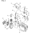
Fig. 3 is an exploded perspective view of the switch inFig. 1 when viewed from a direction different from that inFig. 2 ; -
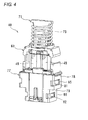
Fig. 4 is a perspective view illustrating an electric magnet device of an embodiment of the present invention; -
Fig. 5 is an exploded perspective view of the electric magnet device inFig. 4 ; -
Fig. 6A is a front sectional view illustrating the switch before an operation; -
Fig. 6B is a side sectional view illustrating the switch inFig. 6A ; -
Fig. 7A is a front sectional view illustrating the switch after the operation; -
Fig. 7B is a side sectional view illustrating the switch inFig. 7A ; -
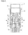
Fig. 8 is a side sectional view illustrating the switch in a state in which an armature is inclined during the operation; -
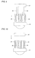
Fig. 9 is a schematic diagram illustrating an electric magnet device according to a second embodiment of the present invention; and -
Fig. 10 is a schematic diagram illustrating an electric magnet device according to a third embodiment of the present invention. - A reset-function-equipped
switch 1 incorporating an electric magnet device according to a first embodiment of the present invention is described with reference to the accompanying drawings ofFigs. 1 to 8 . - As illustrated in
Figs. 1 to 3 , theswitch 1 includes ahousing 10, anoperation piece 13, apower switch mechanism 20, and adrive mechanism 40. - The
housing 10 has a box shape with an upper portion being opened, and thehousing 10 is configured such that thepower switch mechanism 20 is disposed on one side of its inner space while thedrive mechanism 40 is disposed on the other side of the inner space. - The
operation piece 13 has a substantially rectangular box shape with a lower surface being opened, and theoperation piece 13 includes anoperation surface 14, asupport shaft 15, a retention part 16 (seeFig. 6A ), and an abutment plate 17 (seeFig. 6A ). Theoperation surface 14 is formed as a curved surface on the upper surface of theoperation piece 13. Thesupport shaft 15 protrudes outward from center of both side surfaces, opposite to each other, of theoperation piece 13. Theretention part 16 protrudes downward from center of a backside of theoperation surface 14, and acoupling body 21 is fitted in and retained by theretention part 16. Theabutment plate 17 protrudes downward from an end portion of the backside of theoperation surface 14, and abuts on an upper end of anarmature 71. Thesupport shaft 15 is fitted in acircular hole 11 of thehousing 10, whereby theoperation piece 13 is mounted to thehousing 10 so as to be turnable about thesupport shaft 15. - The
power switch mechanism 20 includes a firstpower switch mechanism 20a and a secondpower switch mechanism 20b, which are disposed in parallel in thehousing 10. The first and the secondpower switch mechanism coupling body 21, amovable contact piece 23, a first fixedcontact piece 31, and a second fixedcontact piece 34. - The
coupling body 21 is composed of a coil spring bent into a chevron shape. As illustrated inFig. 6A , with theswitch 1 being assembled, an upper end portion of thecoupling body 21 is fitted in and retained by theretention part 16 of theoperation piece 13, and a lower end portion of thecoupling body 21 is inserted in and supported by aprotrusion 25 of amovable contact piece 23. - As illustrated in
Fig. 3 , themovable contact piece 23 includes asupport part 24 bent into a substantial L-shape and atongue piece 27 that extends obliquely upward from the end portion of thesupport part 24. The chevron-shape protrusion 25 that protrudes upward is formed in a horizontal surface of thesupport part 24. Amovable contact 28 is provided at a leading end of thetongue piece 27. - A first fixed
contact piece 31 has a vertically reverse L-shape, and a first fixedcontact 32 is formed in the upper surface of the first fixedcontact piece 31 by cutting and raising the first fixedcontact piece 31. Similarly, a second fixedcontact piece 34 has a vertically reverse L-shape, and a second fixedcontact 35 is attached to the upper surface of the second fixedcontact piece 34. Because the secondpower switch mechanism 20b is composed of the same components as the firstpower switch mechanism 20a, the same component is designated by the same numeral, and the description thereof is omitted. - As illustrated in
Figs. 4 and5 , thedrive mechanism 40 includes anelectric magnet device 41, acase 60, areturn spring 75, and acover 77. - The
electric magnet device 41 includes abobbin 43 that includes a vertically piercing through-hole 42, acoil 48 that is wound around thebobbin 43, ayoke 50 that is inserted through the through-hole 42 of thebobbin 43 from below, and thearmature 71 that is inserted through the through-hole 42 of thebobbin 43 from above. - The
bobbin 43 includes two coil-windingparts 44 provided in parallel, an upperend edge part 45, and a lowerend edge part 46. Thecoil winding part 44 is cylindrical having a rectangular shape in section, and thecoil 48 is wound around an outer periphery of thecoil winding part 44. The upperend edge part 45 is formed at the upper end of thecoil winding part 44, and the upperend edge part 45 integrally connects the twocoil winding parts 44. The lowerend edge part 46 is composed of a rectangular frame body formed at the lower end of eachcoil winding part 44, a resetsignal input terminal 55 to which a bound leads of thecoil 48 is connected is press-fitted in and fixed to the lowerend edge part 46. - The
yoke 50 is made of a plate-like magnetic material that enhances magnetic efficiency of a permanent magnet 56 (to be described). Theyoke 50 also includes a pair of upwardly extendingarm parts 51, a pair ofnotches 52 that are formed on the lower side of the lateral surface and curved inward into a U-shape, and a linear attachinghole 53 that is formed in the center so as to extend vertically. The rectangular-solid-shapepermanent magnet 56 is fitted in and fixed to the he attachinghole 53. - The
case 60 includes astorage part 61 in which theelectric magnet device 41 is stored, a pair ofguide plates 62 formed above thestorage part 61, and asocket 63 formed below thestorage part 61. An upper-side latching protrusion 65 and a lower-side latching protrusion 66, which protrude outward, are formed in both side surfaces of thecase 60. An insertion hole 67 (seeFig. 6A ) is made in a ceiling surface of thestorage part 61, through which thearmature 71 is inserted thestorage part 61 between theguide plates 62. A pair oflinear protrusions 68 extending vertically from the upper side, a plate-like protrusion 69 extending horizontally in the center, and acurved protrusion 70 including a curved surface protruding inward on the lower side are formed on an inward surface on deep side of thestorage part 61. Thesocket 63 detachably retains a reset signal input plug (not illustrated) connected to the resetsignal input terminal 55. - As illustrated in
Fig. 5 , thearmature 71 is formed into a gate-type plate shape, and includesstep parts 72 that are formed at an upper edge of thearmature 71 to protrude toward both the sides and a pair of downwardly extendingleg parts 73. With thedrive mechanism 40 being assembled, thereturn spring 75 is retained in a compressed state between thestep part 72 of thearmature 71 and the upper surface of thestorage part 61. Therefore, thereturn spring 75 pushes up thearmature 71 to maintain theoperation piece 13 at an off state in which theoperation piece 13 is turned in an off direction. - The
cover 77 has a lateral shape that can laterally be fitted in thecase 60, and includes a pair of upper-sideelastic arm parts 78 extending in parallel from both side edge portions on the upper side and a pair of lower-sideelastic arm parts 79 extending in parallel from both side edge portions on the lower side. A horizontally extending upper-side latching hole 81 is made in the upper-sideelastic arm part 78. A horizontally extending lower-side latching hole 82 is made in the lower-sideelastic arm part 79. - A method for assembling the
drive mechanism 40 will be described as a preceding process of assembling theswitch 1. The lead of thecoil 48 wound around the outer peripheral surface of thecoil winding part 44 of thebobbin 43 is bound and soldered to the resetsignal input terminal 55 fixed to the lowerend edge part 46. Thepermanent magnet 56 is fitted in the attachinghole 53 of theyoke 50, and thearm part 51 is inserted through the through-hole 42 of thebobbin 43 from below, thereby forming theelectric magnet device 41 except thearmature 71. Because thenotch 52 is provided in theyoke 50, theyoke 50 can easily be gripped with a tool through the notch, thereby improving workability. - Then the
electric magnet device 41 is stored in thestorage part 61 of thecase 60. At this point, the upperend edge part 45 of thebobbin 43 abuts on thelinear protrusion 68, and abuts on the ceiling surface of thestorage part 61. Additionally, the lowerend edge part 46 abuts on the upper side surface of the plate-like protrusion 69, whereby theelectric magnet device 41 is positioned in the storage part 61 (case 60). At this point, theyoke 50 is retained and fitted in thestorage part 61 with a play, so that theyoke 50 can oscillate with thearm part 51 being inserted through the through-hole 42. Accordingly, surface contact between thearm part 51 and theleg part 73 of thearmature 71 is facilitated. As illustrated inFig. 6A , because theyoke 50 is sucked to the resetsignal input terminal 55 by a magnetic force of thepermanent magnet 56, theyoke 50 floats from a bottom portion of thecase 60 with a predetermined gap. - Then the
cover 77 is mounted to thecase 60 so as to cover the opening lower side of thecase 60 and thesocket 63. At this point, the upper-side latching hole 81 of thecover 77 is latched in the upper-side latching protrusion 65 of thecase 60, and the lower-side latching hole 82 is latched in the lower-side latching protrusion 66, thereby retaining theelectric magnet device 41. Finally thearmature 71 is inserted through the through-hole 42 of thebobbin 43 through theinsertion hole 67 of thecase 60 while thereturn spring 75 disposed above thestorage part 61 is interposed between thearmature 71 and the through-hole 42, thereby completing thedrive mechanism 40. - Then, as illustrated in
Fig. 3 , the first fixedcontact pieces 31 and the second fixedcontact pieces 34 are inserted in and attached to terminal holes (not illustrated) made in the bottom surface of thehousing 10. The bottom surface of thesupport part 24 of themovable contact piece 23 is turnably placed on the first fixedcontact 32 of the first fixedcontact piece 31. The lower end of thecoupling body 21 is inserted in theprotrusion 25 of themovable contact piece 23, and theretention part 16 of theoperation piece 13 is fitted in the upper end of thecoupling body 21. Thesupport shaft 15 of theoperation piece 13 is fitted in thecircular hole 11 of thehousing 10, and thesupport shaft 15 of theoperation piece 13 is turnably attached to thehousing 10. Therefore, thepower switch mechanism 20 is completed. Finally, as illustrated inFigs. 6 , thedrive mechanism 40 is incorporated from below on the other side of thehousing 10 in which thepower switch mechanism 20 is incorporated, and theswitch 1 is completed. - An operation of the
switch 1 will be described below.
As illustrated inFigs. 6A and 6B , when thepower switch mechanism 20 is in the off state, thereturn spring 75 extends to bias thearmature 71 upward. Therefore, the upper end surface of thearmature 71 pushes up theabutment plate 17, and theoperation piece 13 is in the off state. In the off state, thecoupling body 21 of thepower switch mechanism 20 is bent into the chevron shape toward the side of thedrive mechanism 40. Themovable contact 28 of themovable contact piece 23, which turns with the upper end of the first fixedcontact 32 as a support point, separates from the second fixedcontact 35, and is in the off state. - As illustrated in
Figs. 7A and 7B , when the side of theabutment plate 17 of theoperation surface 14 is pressed downward to turn on theswitch 1, theabutment plate 17 pushes down thearmature 71 against a biasing force of thereturn spring 75. Therefore, thearmature 71 moves downward, theleg part 73 is attracted to thearm part 51 of theyoke 50 due to the magnetic force of thepermanent magnet 56 interposed between opposite surfaces of thearm part 51, and theswitch 1 becomes the on state. - When the
switch 1 is turned on, thecoupling body 21 of thepower switch mechanism 20 is bent into the chevron shape toward the opposite side to thedrive mechanism 40. Therefore, theprotrusion 25 is pressed onto the right side inFigs. 7 , and themovable contact piece 23 turns clockwise inFigs. 7 about the upper end of the first fixedcontact 32. Themovable contact 28 abuts on the second fixedcontact 35 to turn on the power. - As illustrated in
Fig. 8 , in the present invention, theyoke 50 is attached to and fitted in thebobbin 43 with the play, so that theyoke 50 can be inclined according to an inclination of thearmature 71. Accordingly, theleg part 73 and thearm part 51 come into surface contact with each other to decrease a magnetic resistance, and theleg part 73 and thearm part 51 can be attracted to each other with the large attractive force. Therefore, even if a vibration or an impact is applied, the attraction state between theleg part 73 and thearm part 51 can be maintained to prevent the malfunction. - In the embodiment of the present invention, a ratio of an oscillation angle of the
yoke 50 to an oscillation angle of thearmature 71 is preferably greater than 1:1 and less than or equal to 3:1. When the ratio of the oscillation angles of theyoke 50 to thearmature 71 is less than or equal to 1:1, that is for example, 1:0.5, theleg part 73 and thearm part 51 cannot be come into surface contact with each other, and the desired effect cannot be obtained. When the ratio of the oscillation angles of theyoke 50 to thearmature 71 is greater than 3:1, that is for example, 4:1, in attracting thearmature 71 and theyoke 50 to each other, the lower end portion of theleg part 73 comes into contact with an upper-end corner portion of thearm part 51, and an attraction surface on the side of thearmature 71 is abraded to degrade the attractive force. Accordingly, when the ratio of the oscillation angle of theyoke 50 to the oscillation angle of thearmature 71 is greater than 1:1 and less than or equal to 3:1, theleg part 73 and thearm part 51 come surely into surface contact with each other, and the abrasions of the attraction surfaces of theleg part 73 and thearm part 51 can be controlled to prevent the degradation of the attractive force. In the present embodiment, the attraction surfaces of theleg part 73 and thearm part 51 are formed into the square shape, but are not limited thereto. The same effect is obtained even if the attraction surfaces of theleg part 73 and thearm part 51 are formed into a circular shape. The square shape or the circular shape of the attraction surfaces enhances a degree of design freedom. - When a voltage that generates the reverse magnetic force is applied to the
coil 48 through the resetsignal input terminal 55 in order to turn off theswitch 1 in the on state, a magnetic flux of thepermanent magnet 56 is canceled to relatively lower the magnetic force between thearmature 71 and theyoke 50. Therefore, thearmature 71 is pushed upward by the elastic force of thereturn spring 75, and the upper end surface of thearmature 71 pushes up theabutment plate 17. As a result, theoperation piece 13 turns about thesupport shaft 15, and thepower switch mechanism 20 returns to the off state illustrated inFig. 6A . - The present invention is not limited to the above embodiment, but various modifications can be made. In the above embodiment, as to the
yoke 50 and thearmature 71, thearm part 51 and theleg part 73 are inserted through the through-hole 42 of thebobbin 43, but not limited thereto. Alternatively, for example, in an electric magnet device according to a second embodiment illustrated inFig. 9 , a plate-like yoke 85 is disposed on the lower end part of thecoil 48, anarmature 87 including a pair of downwardly extendingleg parts 86 is disposed on the upper end part of thecoil 48. For the sake of convenience, thebobbin 43 is omitted in this electric magnet device. Thearmature 87 is moved downward so that the lower end surfaces of theleg parts 86 are inserted through inside thecoil 48 to be attracted to the upper surface of theyoke 85. At this point, because theyoke 85 is attached to and fitted in thecase 60 with the play, theyoke 85 can be inclined according to the inclination of thearmature 87, and theleg part 86 can come into surface contact with theyoke 85. - As another example, in an electric magnet device according to a third embodiment illustrated in
Fig. 10 , ayoke 91 including a pair of upwardly extendingarm parts 90 inserted through inside thecoil 48 is disposed on the lower end part of thecoil 48, and a plate-like armature 92 is disposed on the upper end part of thecoil 48. For the sake of convenience, thebobbin 43 is omitted in this electric magnet device. The lower surface of thearmature 92 is attracted to the upper end surface of thearm part 90 by moving thearmature 92 downward. At this point, because theyoke 91 is attached to and fitted in thecase 60 with the play, theyoke 91 can be inclined according to the inclination of thearmature 92, and thearmature 92 can come into surface contact with thearm part 90. - The
electric magnet device 41 of the first embodiment includes the pair ofcoils 48, theyoke 50 including the pair ofarm parts 51, and thearmature 71 including the pair ofleg parts 73, but not limited thereto. Alternatively, for example, a configuration in which the electric magnet device includes the one coil, the yoke includes the one arm part, and the armature includes the one leg part may be employed. The electric magnet device of the present invention can of course be applied not only to the switch but also to other electric instruments. - There has thus been shown and described an electromagnetic device and switch using the same which fulfills all the advantages sought therefore. Many changes, modifications, variations and other uses and applications of the subject invention will, however, become apparent to those skilled in the art after considering this specification and the accompanying drawings which disclose the preferred embodiments thereof. All such changes, modifications, variations and other uses and applications which do not depart from the spirit and scope of the invention are deemed to be covered by the invention, which is to be limited only by the claims which follow.
- Although the invention has been described in detail for the purpose of illustration based on what is currently considered to be the most practical and preferred embodiments, it is to be understood that such detail is solely for that purpose and that the invention is not limited to the disclosed embodiments, but, on the contrary, is intended to cover modifications and equivalent arrangements that are within the spirit and scope of the appended claims. For example, it is to be understood that the present invention contemplates that, to the extent possible, one or more features of any embodiment can be combined with one or more features of any other embodiment.
Claims (6)
- An electric magnet device (41) comprising:a coil (48) adapted to insert through at least one of an armature (71, 87) and a yoke (50, 85, 91) so as to attract surfaces of the yoke (50, 85, 91) and the armature (71, 87), which are opposed to each other, to receive a voltage, to excite for separating the surfaces of the yoke (50, 85, 91) and the armature (71, 87);the armature (71, 87) disposed on one end side of the coil (48) andthe yoke (50, 85, 91) disposed on the other end side of the coil (48) and adapted to oscillate,wherein an oscillation angle of the yoke (50, 85, 91) is greater than an oscillation angle of the armature (71,87).
- The electric magnet device (41) according to claim 1, wherein a ratio of the oscillation angle of the yoke (50, 85, 91) to the oscillation angle of the armature (71, 87) is greater than 1:1 and less than or equal to 3:1.
- The electric magnet device (41) according to claim 1 or 2, wherein attraction surfaces of the armature (71, 87) and the yoke (50, 85, 91) have a square shape.
- The electric magnet device (41) according to claim 1 or 2, wherein attraction surfaces of the armature (71, 87) and the yoke (50, 85, 91) have a circular shape.
- The electric magnet device (41) according to any one of claims 1 to 4, wherein the yoke (50, 85, 91) comprises an assembly notch in each of both lateral edge portions of the yoke.
- A switch (1) comprising the electric magnet device (41) according to any one of claims 1 to 5.
Applications Claiming Priority (1)
| Application Number | Priority Date | Filing Date | Title |
|---|---|---|---|
| JP2012199680A JP2014056669A (en) | 2012-09-11 | 2012-09-11 | Electromagnet device and switch employing the same |
Publications (3)
| Publication Number | Publication Date |
|---|---|
| EP2706551A2 true EP2706551A2 (en) | 2014-03-12 |
| EP2706551A3 EP2706551A3 (en) | 2014-04-09 |
| EP2706551B1 EP2706551B1 (en) | 2017-09-06 |
Family
ID=48877161
Family Applications (1)
| Application Number | Title | Priority Date | Filing Date |
|---|---|---|---|
| EP13178744.2A Not-in-force EP2706551B1 (en) | 2012-09-11 | 2013-07-31 | Electric magnet device and switch provided therewith |
Country Status (4)
| Country | Link |
|---|---|
| US (1) | US9117600B2 (en) |
| EP (1) | EP2706551B1 (en) |
| JP (1) | JP2014056669A (en) |
| CN (1) | CN103681070B (en) |
Families Citing this family (2)
| Publication number | Priority date | Publication date | Assignee | Title |
|---|---|---|---|---|
| CN106817666B (en) * | 2017-03-18 | 2019-08-27 | 歌尔股份有限公司 | The welding tooling and welding method of motor vibrator |
| CN107887219B (en) * | 2017-12-14 | 2020-03-20 | 贵派电器股份有限公司 | Switch with electromagnetic control |
Citations (1)
| Publication number | Priority date | Publication date | Assignee | Title |
|---|---|---|---|---|
| JP2001135521A (en) | 1999-11-10 | 2001-05-18 | Tdk Corp | Plunger |
Family Cites Families (39)
| Publication number | Priority date | Publication date | Assignee | Title |
|---|---|---|---|---|
| US3242356A (en) * | 1966-03-22 | Davis, jr electromagnetic device | ||
| US2328831A (en) * | 1941-10-18 | 1943-09-07 | Mendelsohn | Camera synchronizer |
| US2445435A (en) * | 1946-03-08 | 1948-07-20 | Westinghouse Electric Corp | Induction generator starting gear |
| US2490225A (en) * | 1946-06-22 | 1949-12-06 | Samuel Mendelsohn | Camera shutter and flash lamp synchronizer, including lever operated electric generator |
| US2536468A (en) * | 1947-12-10 | 1951-01-02 | Russell Stanley Alexander | Electromagnetic ignition apparatus for fuel gas |
| US2567290A (en) * | 1949-02-23 | 1951-09-11 | Stanley D Livingston | Magneto |
| US3141939A (en) * | 1962-04-09 | 1964-07-21 | Norcon Electronics Inc | Plural contact relay with solenoid actuator |
| NL291152A (en) * | 1962-04-11 | |||
| US3238398A (en) * | 1962-09-18 | 1966-03-01 | Servotronics | Torque motor |
| US3381150A (en) * | 1962-09-18 | 1968-04-30 | Servotronics | Torque motor |
| CH504774A (en) * | 1968-09-27 | 1971-03-15 | Matsushita Electric Works Ltd | Electromagnetic relay |
| JPS5611304Y2 (en) * | 1976-11-15 | 1981-03-13 | ||
| US4322700A (en) * | 1979-12-21 | 1982-03-30 | Bell Telephone Laboratories, Incorporated | Electrical relay apparatus |
| US4518945A (en) * | 1980-11-17 | 1985-05-21 | Leviton Manufacturing Company, Inc. | Remote control system |
| DE3213759A1 (en) * | 1982-04-14 | 1983-10-20 | Siemens AG, 1000 Berlin und 8000 München | ELECTROMAGNETIC RELAY |
| US4656400A (en) * | 1985-07-08 | 1987-04-07 | Synektron Corporation | Variable reluctance actuators having improved constant force control and position-sensing features |
| US4706056A (en) * | 1986-09-11 | 1987-11-10 | American Telephone And Telegraph Company, At&T Bell Laboratories | Electrical relay apparatus |
| JPH0526664Y2 (en) * | 1987-05-28 | 1993-07-06 | ||
| AT396622B (en) * | 1990-02-19 | 1993-10-25 | Avl Verbrennungskraft Messtech | ELECTROMAGNETICALLY ACTUABLE VALVE |
| US5303012A (en) * | 1993-02-10 | 1994-04-12 | Honeywell Inc. | Single magnet latch valve with position indicator |
| JPH06341568A (en) * | 1993-06-03 | 1994-12-13 | Toyota Motor Corp | Solenoid valve device |
| US5584465A (en) * | 1993-12-07 | 1996-12-17 | Snap-Tite, Inc. | Solenoid latching valve |
| US5523684A (en) * | 1994-11-14 | 1996-06-04 | Caterpillar Inc. | Electronic solenoid control apparatus and method with hall effect technology |
| US5942892A (en) * | 1997-10-06 | 1999-08-24 | Husco International, Inc. | Method and apparatus for sensing armature position in direct current solenoid actuators |
| US6293516B1 (en) * | 1999-10-21 | 2001-09-25 | Arichell Technologies, Inc. | Reduced-energy-consumption actuator |
| US6739573B1 (en) * | 1999-10-28 | 2004-05-25 | Siemens Canada Limited | Canister purge valve noise attenuation |
| US6305662B1 (en) * | 2000-02-29 | 2001-10-23 | Arichell Technologies, Inc. | Reduced-energy-consumption actuator |
| US6948697B2 (en) * | 2000-02-29 | 2005-09-27 | Arichell Technologies, Inc. | Apparatus and method for controlling fluid flow |
| US6853276B2 (en) | 2001-09-20 | 2005-02-08 | Richard G. Smith | Electromagnetic formed contact surface |
| US6933630B2 (en) * | 2002-06-06 | 2005-08-23 | Braun Gmbh | Drive mechanisms for small electric appliances |
| AT8202U1 (en) * | 2003-08-28 | 2006-03-15 | Naimer H L | ELECTROMAGNETIC SWITCHING ELEMENT WITH CROPPED POLISHED SURFACES |
| JP2006066766A (en) | 2004-08-30 | 2006-03-09 | Mitsumi Electric Co Ltd | Small plunger |
| FR2895594B1 (en) * | 2005-12-22 | 2008-03-07 | Sagem Defense Securite | DEVICE FOR LINEAR DISPLACEMENT OF A BODY BETWEEN TWO PREDETERMINED POSITIONS |
| US8026781B2 (en) * | 2007-08-21 | 2011-09-27 | Anthony Freakes | Solenoid device with stable activation |
| JP5175537B2 (en) * | 2007-12-14 | 2013-04-03 | 豊興工業株式会社 | solenoid valve |
| JP5280792B2 (en) * | 2008-10-08 | 2013-09-04 | 三菱電機株式会社 | Electromagnetic actuator |
| DE202008015303U1 (en) * | 2008-11-19 | 2009-03-26 | Bürkert Werke GmbH & Co. KG | Lifting armature drive |
| JP5664432B2 (en) * | 2010-06-21 | 2015-02-04 | 日産自動車株式会社 | Electromagnetic relay |
| DE202011004616U1 (en) * | 2011-03-30 | 2011-06-09 | Bürkert Werke GmbH, 74653 | Lifting armature drive |
-
2012
- 2012-09-11 JP JP2012199680A patent/JP2014056669A/en active Pending
-
2013
- 2013-07-30 US US13/953,963 patent/US9117600B2/en active Active
- 2013-07-30 CN CN201310326260.3A patent/CN103681070B/en not_active Expired - Fee Related
- 2013-07-31 EP EP13178744.2A patent/EP2706551B1/en not_active Not-in-force
Patent Citations (1)
| Publication number | Priority date | Publication date | Assignee | Title |
|---|---|---|---|---|
| JP2001135521A (en) | 1999-11-10 | 2001-05-18 | Tdk Corp | Plunger |
Also Published As
| Publication number | Publication date |
|---|---|
| US20140070909A1 (en) | 2014-03-13 |
| CN103681070B (en) | 2016-07-06 |
| EP2706551B1 (en) | 2017-09-06 |
| JP2014056669A (en) | 2014-03-27 |
| US9117600B2 (en) | 2015-08-25 |
| EP2706551A3 (en) | 2014-04-09 |
| CN103681070A (en) | 2014-03-26 |
Similar Documents
| Publication | Publication Date | Title |
|---|---|---|
| CN103339706B (en) | Electromagnetic relay | |
| CN110223868B (en) | Electromagnetic Relay | |
| EP2806442A1 (en) | Switch and control method thereof | |
| EP2768004B1 (en) | Electromagnetic relay | |
| JP5446780B2 (en) | Electromagnetic relay | |
| WO2015068377A1 (en) | Power generation device | |
| JP6056264B2 (en) | Electromagnet device and electromagnetic relay using the same | |
| JP2013084559A (en) | Electromagnetic relay | |
| US8963660B2 (en) | Electromagnetic relay | |
| JP2014044837A5 (en) | ||
| JP2007048705A (en) | Relay | |
| EP2706551B1 (en) | Electric magnet device and switch provided therewith | |
| JP6172633B2 (en) | Contact device and electromagnetic relay equipped with the contact device | |
| JP5591132B2 (en) | Permanent magnet actuated switch | |
| JP4953828B2 (en) | Electromagnet device and electromagnetic relay | |
| JP7120057B2 (en) | electromagnet device | |
| JP4363462B2 (en) | High frequency relay | |
| JP2016076604A (en) | Motor unit with clutch mechanism | |
| JP5406636B2 (en) | Coaxial relay | |
| JP7468277B2 (en) | Electromagnetic Relay | |
| JP4855273B2 (en) | Electromagnet device and electromagnetic relay | |
| JP3937483B2 (en) | Electromagnetic relay | |
| JP4920095B2 (en) | Electromagnetic solenoid | |
| US20090219120A1 (en) | Electromagnet device | |
| JP2017139194A (en) | Electromagnetic relay |
Legal Events
| Date | Code | Title | Description |
|---|---|---|---|
| PUAL | Search report despatched |
Free format text: ORIGINAL CODE: 0009013 |
|
| PUAI | Public reference made under article 153(3) epc to a published international application that has entered the european phase |
Free format text: ORIGINAL CODE: 0009012 |
|
| AK | Designated contracting states |
Kind code of ref document: A2 Designated state(s): AL AT BE BG CH CY CZ DE DK EE ES FI FR GB GR HR HU IE IS IT LI LT LU LV MC MK MT NL NO PL PT RO RS SE SI SK SM TR |
|
| AX | Request for extension of the european patent |
Extension state: BA ME |
|
| AK | Designated contracting states |
Kind code of ref document: A3 Designated state(s): AL AT BE BG CH CY CZ DE DK EE ES FI FR GB GR HR HU IE IS IT LI LT LU LV MC MK MT NL NO PL PT RO RS SE SI SK SM TR |
|
| AX | Request for extension of the european patent |
Extension state: BA ME |
|
| RIC1 | Information provided on ipc code assigned before grant |
Ipc: H01H 50/22 20060101ALI20140303BHEP Ipc: H01H 51/01 20060101ALI20140303BHEP Ipc: H01H 50/30 20060101AFI20140303BHEP Ipc: H01H 50/16 20060101ALI20140303BHEP Ipc: H01H 50/04 20060101ALI20140303BHEP |
|
| 17P | Request for examination filed |
Effective date: 20141009 |
|
| RBV | Designated contracting states (corrected) |
Designated state(s): AL AT BE BG CH CY CZ DE DK EE ES FI FR GB GR HR HU IE IS IT LI LT LU LV MC MK MT NL NO PL PT RO RS SE SI SK SM TR |
|
| 17Q | First examination report despatched |
Effective date: 20160810 |
|
| STAA | Information on the status of an ep patent application or granted ep patent |
Free format text: STATUS: EXAMINATION IS IN PROGRESS |
|
| GRAP | Despatch of communication of intention to grant a patent |
Free format text: ORIGINAL CODE: EPIDOSNIGR1 |
|
| STAA | Information on the status of an ep patent application or granted ep patent |
Free format text: STATUS: GRANT OF PATENT IS INTENDED |
|
| INTG | Intention to grant announced |
Effective date: 20170331 |
|
| GRAS | Grant fee paid |
Free format text: ORIGINAL CODE: EPIDOSNIGR3 |
|
| GRAA | (expected) grant |
Free format text: ORIGINAL CODE: 0009210 |
|
| STAA | Information on the status of an ep patent application or granted ep patent |
Free format text: STATUS: THE PATENT HAS BEEN GRANTED |
|
| AK | Designated contracting states |
Kind code of ref document: B1 Designated state(s): AL AT BE BG CH CY CZ DE DK EE ES FI FR GB GR HR HU IE IS IT LI LT LU LV MC MK MT NL NO PL PT RO RS SE SI SK SM TR |
|
| REG | Reference to a national code |
Ref country code: GB Ref legal event code: FG4D |
|
| REG | Reference to a national code |
Ref country code: CH Ref legal event code: EP Ref country code: AT Ref legal event code: REF Ref document number: 926701 Country of ref document: AT Kind code of ref document: T Effective date: 20170915 |
|
| REG | Reference to a national code |
Ref country code: IE Ref legal event code: FG4D |
|
| REG | Reference to a national code |
Ref country code: DE Ref legal event code: R096 Ref document number: 602013026064 Country of ref document: DE |
|
| REG | Reference to a national code |
Ref country code: NL Ref legal event code: MP Effective date: 20170906 |
|
| REG | Reference to a national code |
Ref country code: LT Ref legal event code: MG4D |
|
| PG25 | Lapsed in a contracting state [announced via postgrant information from national office to epo] |
Ref country code: HR Free format text: LAPSE BECAUSE OF FAILURE TO SUBMIT A TRANSLATION OF THE DESCRIPTION OR TO PAY THE FEE WITHIN THE PRESCRIBED TIME-LIMIT Effective date: 20170906 Ref country code: LT Free format text: LAPSE BECAUSE OF FAILURE TO SUBMIT A TRANSLATION OF THE DESCRIPTION OR TO PAY THE FEE WITHIN THE PRESCRIBED TIME-LIMIT Effective date: 20170906 Ref country code: FI Free format text: LAPSE BECAUSE OF FAILURE TO SUBMIT A TRANSLATION OF THE DESCRIPTION OR TO PAY THE FEE WITHIN THE PRESCRIBED TIME-LIMIT Effective date: 20170906 Ref country code: NO Free format text: LAPSE BECAUSE OF FAILURE TO SUBMIT A TRANSLATION OF THE DESCRIPTION OR TO PAY THE FEE WITHIN THE PRESCRIBED TIME-LIMIT Effective date: 20171206 Ref country code: SE Free format text: LAPSE BECAUSE OF FAILURE TO SUBMIT A TRANSLATION OF THE DESCRIPTION OR TO PAY THE FEE WITHIN THE PRESCRIBED TIME-LIMIT Effective date: 20170906 |
|
| REG | Reference to a national code |
Ref country code: AT Ref legal event code: MK05 Ref document number: 926701 Country of ref document: AT Kind code of ref document: T Effective date: 20170906 |
|
| PG25 | Lapsed in a contracting state [announced via postgrant information from national office to epo] |
Ref country code: BG Free format text: LAPSE BECAUSE OF FAILURE TO SUBMIT A TRANSLATION OF THE DESCRIPTION OR TO PAY THE FEE WITHIN THE PRESCRIBED TIME-LIMIT Effective date: 20171206 Ref country code: GR Free format text: LAPSE BECAUSE OF FAILURE TO SUBMIT A TRANSLATION OF THE DESCRIPTION OR TO PAY THE FEE WITHIN THE PRESCRIBED TIME-LIMIT Effective date: 20171207 Ref country code: RS Free format text: LAPSE BECAUSE OF FAILURE TO SUBMIT A TRANSLATION OF THE DESCRIPTION OR TO PAY THE FEE WITHIN THE PRESCRIBED TIME-LIMIT Effective date: 20170906 Ref country code: ES Free format text: LAPSE BECAUSE OF FAILURE TO SUBMIT A TRANSLATION OF THE DESCRIPTION OR TO PAY THE FEE WITHIN THE PRESCRIBED TIME-LIMIT Effective date: 20170906 Ref country code: LV Free format text: LAPSE BECAUSE OF FAILURE TO SUBMIT A TRANSLATION OF THE DESCRIPTION OR TO PAY THE FEE WITHIN THE PRESCRIBED TIME-LIMIT Effective date: 20170906 |
|
| PG25 | Lapsed in a contracting state [announced via postgrant information from national office to epo] |
Ref country code: NL Free format text: LAPSE BECAUSE OF FAILURE TO SUBMIT A TRANSLATION OF THE DESCRIPTION OR TO PAY THE FEE WITHIN THE PRESCRIBED TIME-LIMIT Effective date: 20170906 |
|
| PG25 | Lapsed in a contracting state [announced via postgrant information from national office to epo] |
Ref country code: RO Free format text: LAPSE BECAUSE OF FAILURE TO SUBMIT A TRANSLATION OF THE DESCRIPTION OR TO PAY THE FEE WITHIN THE PRESCRIBED TIME-LIMIT Effective date: 20170906 Ref country code: PL Free format text: LAPSE BECAUSE OF FAILURE TO SUBMIT A TRANSLATION OF THE DESCRIPTION OR TO PAY THE FEE WITHIN THE PRESCRIBED TIME-LIMIT Effective date: 20170906 Ref country code: CZ Free format text: LAPSE BECAUSE OF FAILURE TO SUBMIT A TRANSLATION OF THE DESCRIPTION OR TO PAY THE FEE WITHIN THE PRESCRIBED TIME-LIMIT Effective date: 20170906 |
|
| PG25 | Lapsed in a contracting state [announced via postgrant information from national office to epo] |
Ref country code: AT Free format text: LAPSE BECAUSE OF FAILURE TO SUBMIT A TRANSLATION OF THE DESCRIPTION OR TO PAY THE FEE WITHIN THE PRESCRIBED TIME-LIMIT Effective date: 20170906 Ref country code: EE Free format text: LAPSE BECAUSE OF FAILURE TO SUBMIT A TRANSLATION OF THE DESCRIPTION OR TO PAY THE FEE WITHIN THE PRESCRIBED TIME-LIMIT Effective date: 20170906 Ref country code: IT Free format text: LAPSE BECAUSE OF FAILURE TO SUBMIT A TRANSLATION OF THE DESCRIPTION OR TO PAY THE FEE WITHIN THE PRESCRIBED TIME-LIMIT Effective date: 20170906 Ref country code: IS Free format text: LAPSE BECAUSE OF FAILURE TO SUBMIT A TRANSLATION OF THE DESCRIPTION OR TO PAY THE FEE WITHIN THE PRESCRIBED TIME-LIMIT Effective date: 20180106 Ref country code: SM Free format text: LAPSE BECAUSE OF FAILURE TO SUBMIT A TRANSLATION OF THE DESCRIPTION OR TO PAY THE FEE WITHIN THE PRESCRIBED TIME-LIMIT Effective date: 20170906 Ref country code: SK Free format text: LAPSE BECAUSE OF FAILURE TO SUBMIT A TRANSLATION OF THE DESCRIPTION OR TO PAY THE FEE WITHIN THE PRESCRIBED TIME-LIMIT Effective date: 20170906 |
|
| REG | Reference to a national code |
Ref country code: DE Ref legal event code: R097 Ref document number: 602013026064 Country of ref document: DE |
|
| PLBE | No opposition filed within time limit |
Free format text: ORIGINAL CODE: 0009261 |
|
| STAA | Information on the status of an ep patent application or granted ep patent |
Free format text: STATUS: NO OPPOSITION FILED WITHIN TIME LIMIT |
|
| PG25 | Lapsed in a contracting state [announced via postgrant information from national office to epo] |
Ref country code: DK Free format text: LAPSE BECAUSE OF FAILURE TO SUBMIT A TRANSLATION OF THE DESCRIPTION OR TO PAY THE FEE WITHIN THE PRESCRIBED TIME-LIMIT Effective date: 20170906 |
|
| 26N | No opposition filed |
Effective date: 20180607 |
|
| PG25 | Lapsed in a contracting state [announced via postgrant information from national office to epo] |
Ref country code: SI Free format text: LAPSE BECAUSE OF FAILURE TO SUBMIT A TRANSLATION OF THE DESCRIPTION OR TO PAY THE FEE WITHIN THE PRESCRIBED TIME-LIMIT Effective date: 20170906 |
|
| REG | Reference to a national code |
Ref country code: CH Ref legal event code: PL |
|
| GBPC | Gb: european patent ceased through non-payment of renewal fee |
Effective date: 20180731 |
|
| PG25 | Lapsed in a contracting state [announced via postgrant information from national office to epo] |
Ref country code: LU Free format text: LAPSE BECAUSE OF NON-PAYMENT OF DUE FEES Effective date: 20180731 Ref country code: MC Free format text: LAPSE BECAUSE OF FAILURE TO SUBMIT A TRANSLATION OF THE DESCRIPTION OR TO PAY THE FEE WITHIN THE PRESCRIBED TIME-LIMIT Effective date: 20170906 |
|
| REG | Reference to a national code |
Ref country code: BE Ref legal event code: MM Effective date: 20180731 |
|
| PG25 | Lapsed in a contracting state [announced via postgrant information from national office to epo] |
Ref country code: CH Free format text: LAPSE BECAUSE OF NON-PAYMENT OF DUE FEES Effective date: 20180731 Ref country code: GB Free format text: LAPSE BECAUSE OF NON-PAYMENT OF DUE FEES Effective date: 20180731 Ref country code: FR Free format text: LAPSE BECAUSE OF NON-PAYMENT OF DUE FEES Effective date: 20180731 Ref country code: LI Free format text: LAPSE BECAUSE OF NON-PAYMENT OF DUE FEES Effective date: 20180731 |
|
| REG | Reference to a national code |
Ref country code: IE Ref legal event code: MM4A |
|
| PG25 | Lapsed in a contracting state [announced via postgrant information from national office to epo] |
Ref country code: BE Free format text: LAPSE BECAUSE OF NON-PAYMENT OF DUE FEES Effective date: 20180731 |
|
| PG25 | Lapsed in a contracting state [announced via postgrant information from national office to epo] |
Ref country code: IE Free format text: LAPSE BECAUSE OF NON-PAYMENT OF DUE FEES Effective date: 20180731 |
|
| PG25 | Lapsed in a contracting state [announced via postgrant information from national office to epo] |
Ref country code: MT Free format text: LAPSE BECAUSE OF NON-PAYMENT OF DUE FEES Effective date: 20180731 |
|
| PG25 | Lapsed in a contracting state [announced via postgrant information from national office to epo] |
Ref country code: TR Free format text: LAPSE BECAUSE OF FAILURE TO SUBMIT A TRANSLATION OF THE DESCRIPTION OR TO PAY THE FEE WITHIN THE PRESCRIBED TIME-LIMIT Effective date: 20170906 |
|
| PG25 | Lapsed in a contracting state [announced via postgrant information from national office to epo] |
Ref country code: PT Free format text: LAPSE BECAUSE OF FAILURE TO SUBMIT A TRANSLATION OF THE DESCRIPTION OR TO PAY THE FEE WITHIN THE PRESCRIBED TIME-LIMIT Effective date: 20170906 Ref country code: HU Free format text: LAPSE BECAUSE OF FAILURE TO SUBMIT A TRANSLATION OF THE DESCRIPTION OR TO PAY THE FEE WITHIN THE PRESCRIBED TIME-LIMIT; INVALID AB INITIO Effective date: 20130731 |
|
| PG25 | Lapsed in a contracting state [announced via postgrant information from national office to epo] |
Ref country code: MK Free format text: LAPSE BECAUSE OF NON-PAYMENT OF DUE FEES Effective date: 20170906 Ref country code: CY Free format text: LAPSE BECAUSE OF FAILURE TO SUBMIT A TRANSLATION OF THE DESCRIPTION OR TO PAY THE FEE WITHIN THE PRESCRIBED TIME-LIMIT Effective date: 20170906 |
|
| PG25 | Lapsed in a contracting state [announced via postgrant information from national office to epo] |
Ref country code: AL Free format text: LAPSE BECAUSE OF FAILURE TO SUBMIT A TRANSLATION OF THE DESCRIPTION OR TO PAY THE FEE WITHIN THE PRESCRIBED TIME-LIMIT Effective date: 20170906 |
|
| PGFP | Annual fee paid to national office [announced via postgrant information from national office to epo] |
Ref country code: DE Payment date: 20220608 Year of fee payment: 10 |
|
| REG | Reference to a national code |
Ref country code: DE Ref legal event code: R119 Ref document number: 602013026064 Country of ref document: DE |
|
| PG25 | Lapsed in a contracting state [announced via postgrant information from national office to epo] |
Ref country code: DE Free format text: LAPSE BECAUSE OF NON-PAYMENT OF DUE FEES Effective date: 20240201 |