EP2706406A2 - Optical vortex laser vibration method and optical vortex laser vibration device - Google Patents
Optical vortex laser vibration method and optical vortex laser vibration device Download PDFInfo
- Publication number
- EP2706406A2 EP2706406A2 EP12796232.2A EP12796232A EP2706406A2 EP 2706406 A2 EP2706406 A2 EP 2706406A2 EP 12796232 A EP12796232 A EP 12796232A EP 2706406 A2 EP2706406 A2 EP 2706406A2
- Authority
- EP
- European Patent Office
- Prior art keywords
- optical vortex
- optical
- oscillation device
- laser
- resonator
- Prior art date
- Legal status (The legal status is an assumption and is not a legal conclusion. Google has not performed a legal analysis and makes no representation as to the accuracy of the status listed.)
- Granted
Links
- 230000003287 optical effect Effects 0.000 title claims abstract description 216
- 238000000034 method Methods 0.000 title claims description 35
- 230000010355 oscillation Effects 0.000 claims abstract description 68
- 229910012463 LiTaO3 Inorganic materials 0.000 claims abstract description 8
- 229910003327 LiNbO3 Inorganic materials 0.000 claims abstract description 7
- 230000001427 coherent effect Effects 0.000 claims description 15
- 238000006243 chemical reaction Methods 0.000 claims description 10
- 230000005284 excitation Effects 0.000 claims description 6
- 230000001678 irradiating effect Effects 0.000 claims description 3
- 230000010287 polarization Effects 0.000 description 6
- 238000002834 transmittance Methods 0.000 description 4
- 238000002474 experimental method Methods 0.000 description 3
- 239000000835 fiber Substances 0.000 description 3
- 230000008878 coupling Effects 0.000 description 2
- 238000010168 coupling process Methods 0.000 description 2
- 238000005859 coupling reaction Methods 0.000 description 2
- 230000007850 degeneration Effects 0.000 description 2
- 230000000694 effects Effects 0.000 description 2
- 238000002310 reflectometry Methods 0.000 description 2
- 229910017502 Nd:YVO4 Inorganic materials 0.000 description 1
- 238000002679 ablation Methods 0.000 description 1
- 238000004519 manufacturing process Methods 0.000 description 1
- 239000000463 material Substances 0.000 description 1
- 238000005259 measurement Methods 0.000 description 1
- 239000002184 metal Substances 0.000 description 1
- 238000012986 modification Methods 0.000 description 1
- 230000004048 modification Effects 0.000 description 1
- 230000000737 periodic effect Effects 0.000 description 1
- 238000012545 processing Methods 0.000 description 1
- 230000005855 radiation Effects 0.000 description 1
- 239000004065 semiconductor Substances 0.000 description 1
- 230000003595 spectral effect Effects 0.000 description 1
- 230000009466 transformation Effects 0.000 description 1
Images










Classifications
-
- H—ELECTRICITY
- H01—ELECTRIC ELEMENTS
- H01S—DEVICES USING THE PROCESS OF LIGHT AMPLIFICATION BY STIMULATED EMISSION OF RADIATION [LASER] TO AMPLIFY OR GENERATE LIGHT; DEVICES USING STIMULATED EMISSION OF ELECTROMAGNETIC RADIATION IN WAVE RANGES OTHER THAN OPTICAL
- H01S3/00—Lasers, i.e. devices using stimulated emission of electromagnetic radiation in the infrared, visible or ultraviolet wave range
- H01S3/10—Controlling the intensity, frequency, phase, polarisation or direction of the emitted radiation, e.g. switching, gating, modulating or demodulating
- H01S3/106—Controlling the intensity, frequency, phase, polarisation or direction of the emitted radiation, e.g. switching, gating, modulating or demodulating by controlling devices placed within the cavity
- H01S3/108—Controlling the intensity, frequency, phase, polarisation or direction of the emitted radiation, e.g. switching, gating, modulating or demodulating by controlling devices placed within the cavity using non-linear optical devices, e.g. exhibiting Brillouin or Raman scattering
- H01S3/1083—Controlling the intensity, frequency, phase, polarisation or direction of the emitted radiation, e.g. switching, gating, modulating or demodulating by controlling devices placed within the cavity using non-linear optical devices, e.g. exhibiting Brillouin or Raman scattering using parametric generation
-
- G—PHYSICS
- G02—OPTICS
- G02F—OPTICAL DEVICES OR ARRANGEMENTS FOR THE CONTROL OF LIGHT BY MODIFICATION OF THE OPTICAL PROPERTIES OF THE MEDIA OF THE ELEMENTS INVOLVED THEREIN; NON-LINEAR OPTICS; FREQUENCY-CHANGING OF LIGHT; OPTICAL LOGIC ELEMENTS; OPTICAL ANALOGUE/DIGITAL CONVERTERS
- G02F1/00—Devices or arrangements for the control of the intensity, colour, phase, polarisation or direction of light arriving from an independent light source, e.g. switching, gating or modulating; Non-linear optics
- G02F1/35—Non-linear optics
- G02F1/39—Non-linear optics for parametric generation or amplification of light, infrared or ultraviolet waves
-
- G—PHYSICS
- G02—OPTICS
- G02F—OPTICAL DEVICES OR ARRANGEMENTS FOR THE CONTROL OF LIGHT BY MODIFICATION OF THE OPTICAL PROPERTIES OF THE MEDIA OF THE ELEMENTS INVOLVED THEREIN; NON-LINEAR OPTICS; FREQUENCY-CHANGING OF LIGHT; OPTICAL LOGIC ELEMENTS; OPTICAL ANALOGUE/DIGITAL CONVERTERS
- G02F2202/00—Materials and properties
- G02F2202/20—LiNbO3, LiTaO3
-
- H—ELECTRICITY
- H01—ELECTRIC ELEMENTS
- H01S—DEVICES USING THE PROCESS OF LIGHT AMPLIFICATION BY STIMULATED EMISSION OF RADIATION [LASER] TO AMPLIFY OR GENERATE LIGHT; DEVICES USING STIMULATED EMISSION OF ELECTROMAGNETIC RADIATION IN WAVE RANGES OTHER THAN OPTICAL
- H01S3/00—Lasers, i.e. devices using stimulated emission of electromagnetic radiation in the infrared, visible or ultraviolet wave range
- H01S3/005—Optical devices external to the laser cavity, specially adapted for lasers, e.g. for homogenisation of the beam or for manipulating laser pulses, e.g. pulse shaping
- H01S3/0092—Nonlinear frequency conversion, e.g. second harmonic generation [SHG] or sum- or difference-frequency generation outside the laser cavity
Definitions
- the present invention relates to a method for oscillating an optical vortex laser and an optical vortex oscillation device.
- An optical vortex is a light wave that is characterized by angular momentum (orbital angular momentum) originates from phase singular point and doughnut-type intensity distribution.
- a representative example of an optical vortex may be Laguerre Gaussian Beam (for example, see non-patent literature described below).
- Laguerre Gaussian Beam is eigensolution of wave equation in cylindrical coordinate system and satisfies a periodic boundary condition in which phase rotates only integral multiplication of 2 ⁇ in every one wavelength propagation around center of rotation.
- Orbital angular momentum operates on a direction given by vector difference between a normal direction thereof and a light propagation direction.
- an optical vortex can be employed for light manipulation using radiation pressure of light, a high resolution microscope using phase singular point, optical vortex ablation processing positively using orbital angular momentum, and future industrial applications thereof are largely expected.
- Exemplary methods for generating an optical vortex include: (1) a method using a bounce cavity (for example, non-patent literature 2 described below), (2) a method using a multi-mode area fiber amplifier (for example, non-patent literature 3 described below), (3) a method using a phase plate (for example, non-patent literature 4), and (4) a method using a space phase modulator (for example, non-patent literature 5).
- quantum number of an optical vortex which can be generated is limited to low dimensions such as +1, -1, and the like. Furthermore, the quantum number is only an integer.
- an object of the present invention to provide an optical vortex laser oscillation device which can have high power and can generate an optical vortex even in a wide frequency range and if the optical vortex has quantum number which is not an integer.
- a method for oscillating an optical vortex laser is characterized by irradiating an optical vortex of pulse excitation into an optical parametric oscillation system, generating a plurality of coherent optical vortices, and varying quantum number of orbital angular momentum to perform frequency conversion.
- an optical parametric oscillation system is not limited.
- the optical parametric oscillation system preferably comprises a resonator, wherein the resonator includes a non-linear medium and a pair of resonator mirrors sandwiching the non-linear medium.
- radius of curvature for the resonator mirrors is not limited.
- the radius of curvature for the resonator mirrors is preferably five times greater than length of a resonator formed by the pair of resonator mirrors.
- a pair of resonator mirrors is not limited.
- the pair of resonator mirrors is preferably a parallel flat plate.
- the method for oscillating an optical vortex laser according to one aspect of the present invention is not limited. However, it is preferable to vary a degeneration state of quantum number of angular momentum by changing resonance condition in the resonator.
- the method for oscillating an optical vortex laser according to one aspect of the present invention is not limited.
- the quantum number of orbital angular momentum is preferably a non-degenerate state.
- the method for oscillating an optical vortex laser according to one aspect of the present invention is not limited. However, it is preferable to generate multi-frequency by generating a plurality of coherent optical vortices.
- the method for oscillating an optical vortex laser according to one aspect of the present invention is not limited. However, it is preferable to generate difference frequency.
- the method for oscillating an optical vortex laser according to one aspect of the present invention is not limited. However, it is preferable to rotate a non-linear medium.
- the method for oscillating an optical vortex laser according to one aspect of the present invention is not limited. However, it is preferable to change temperature of the non-linear medium.
- the non-linear medium preferably includes at least any one of KTiOPO 4 , periodically polarization-reversed LiNbO 3 , and periodically polarization-reversed LiTaO 3 .
- An optical vortex laser oscillation device is characterized by comprising: a laser light source for generating laser light of pulse excitation; an optical vortex generation unit for generating an excited optical vortex on the basis of the laser light generated by the laser light source; and an optical parametric oscillation system for generating a plurality of coherent optical vortices on the basis of the excited optical vortex generated by the optical vortex generation unit and changing quantum number of orbital angular momentum to perform frequency conversion.
- a parametric oscillation system is not limited.
- the parametric oscillation system preferably comprises a non-linear medium and a pair of resonator mirrors sandwiching the non-linear medium.
- radius curvature for the resonator mirrors is not limited.
- the radius of curvature for the resonator mirrors is preferably five times greater than length of a resonator formed by the pair of resonator mirrors.
- a pair of resonator mirrors is not limited.
- the pair of resonator mirrors is preferably a parallel flat plate.
- the optical vortex laser oscillation device is not limited. However, it is preferable to vary a degeneration state of the quantum number of angular momentum by changing resonance condition in a resonator.
- quantum number of orbital angular momentum is not limited.
- the quantum number of orbital angular momentum is preferably a non-degenerate state.
- the optical vortex laser oscillation device is not limited. However, it is preferable to generate multi-frequency by generating the plurality of coherent optical vortices.
- the optical vortex laser oscillation device is not limited. However, it is preferable to generate difference frequency.
- the optical vortex laser oscillation device is not limited. However, it is preferable to rotate the non-linear medium.
- the optical vortex laser oscillation device is not limited. However, it is preferable to change temperature of the non-linear medium.
- a non-linear medium is not limited.
- the non-linear medium preferably includes at least any one of KTiOPO 4 , periodically polarization-reversed LiNbO 3 , and periodically polarization-reversed LiTaO 3 .
- An optical vortex laser oscillation device is characterized by comprising: a laser light source for generating laser light; an optical vortex generation unit for generating an excited optical vortex on the basis of the laser light generated by the laser light source; and an optical resonance unit for resonating the excited optical vortex generated by the optical vortex generation unit and dividing the excited optical vortex into signal light and idler light.
- the optical resonance unit is not limited.
- the optical resonance unit preferably includes a non-linear medium and a pair of resonator mirrors sandwiching the non-linear medium.
- radius of curvature for the resonator mirrors is not limited.
- the radius of curvature for the resonator mirrors is preferably five times greater than length of a resonator formed by the pair of resonator mirrors.
- a ratio of photon energy of idler light with respect to photon energy of signal light is not limited.
- the ratio is preferably 0.8 or more and 1.2 or less.
- the non-linear medium is not limited.
- the non-linear medium preferably includes at least any one of KTiOPO 4 , periodically polarization-reversed LiNbO 3 , and periodically polarization-reversed LiTaO 3 .
- the present invention provides an optical vortex oscillation device which can have high power, and can be operated even in a wide frequency range and if an optical vortex is quantum number which is not an integer.
- An optical vortex laser oscillation device (hereinafter, referred to as "the present laser device") according to the present embodiment comprises a laser light source for generating laser light of pulse excitation, an optical vortex generation unit for generating an excited optical vortex based on the laser light generated by the laser light source, and an optical parametric oscillation system for generating a plurality of coherent optical vortices based on the excited optical vortex generated by the optical vortex generation unit and varying quantum number of orbital angular momentum to perform frequency conversion.
- the optical parametric oscillation system means an optical system that generates a plurality of coherent optical vortices based on the excited optical vortex generated by the optical vortex generation unit and that changes the quantum number of orbital angular momentum to perform frequency conversion.
- Configuration of the optical parametric oscillation system is not limited as far as its function is maintained.
- Specific example thereof may be an optical system that includes a pair of resonator mirrors and a medium sandwiched between the pair of resonator mirrors, i.e., an optical resonance unit. More specific example thereof is described below.
- FIG. 1 is a drawing that schematically shows an optical system of an optical vortex laser oscillation device (hereinafter, referred to as "the present laser device") according to the present embodiment.
- the present laser device 1 includes a laser light source 2 for generating laser light B1, an optical vortex generation unit 3 for generating an excited optical vortex B2 based on the laser light B1 which the laser light source 2 generates, and an optical resonance unit 4 for resonating the excited optical vortex B2 which the optical vortex generation unit generates and for dividing the excited optical vortex B2 into signal light and idler light.
- the laser light source 2 can generate the laser light B1 described above.
- the laser light source 2 is not limited as far as the above mentioned function is maintained. Examples thereof include a solid-state laser such as YAG laser, a dye laser, a gas laser such as He-Ne laser, a semiconductor laser such as LD laser, and the like.
- Wavelength region of light emitted from the laser light source 2 in the present embodiment is preferably in the outside range of visible region. Wavelength region of emitted light is preferably 800 nm or more, and more preferably 1000 nm or more. Within this wavelength region, it is possible to obtain light from visible wavelength region to middle infrared region in the optical resonance unit 4.
- the laser light source 2 is preferably a pulse oscillation laser light source for generating pulse laser light.
- the pulse oscillation laser light source has wider spectral width than a continuous oscillation laser light source.
- the pulse oscillation laser light source is applicable because it emits high power laser light. Coherent coupling is difficult to occur in the continuous oscillation laser light source, whereas coherent coupling is easy to occur in the pulse oscillation laser light source.
- the optical vortex generation unit 3 can generate the excited optical vortex B2 based on the laser light B1 which the laser light source 2 generates.
- the optical vortex generation unit 3 is not limited and may use a phase plate, a space phase modulator, a multi-mode area fiber amplifier, or the like. Furthermore, configuration in which the laser light source 2 and the optical vortex generation unit 3 are directly united to generate an optical vortex may be employed.
- the optical vortex generated by the optical vortex generation unit 3 is more preferably a coherent optical vortex.
- the optical resonance unit 4 can resonate the excited optical vortex B2 generated by the optical vortex generation unit and generate a plurality of coherent optical vortices, and change quantum number of orbital angular momentum to perform frequency conversion. Specifically, it is possible to divide into signal light and idler light. Furthermore, an optical vortex generated from an optical parametric oscillation system (an optical resonance unit) according to the present embodiment can arbitrarily change quantum number of starting angular momentum by varying resonance condition, thereby enabling the plurality of quantum number of light to be a degenerate state, and also to be a non-degenerate state.
- the optical resonance unit 4 is not limited.
- the optical resonance unit 4 preferably includes a non-linear medium 41 and a pair of resonator mirrors 42 sandwiching the non-linear medium 41.
- wavelength of light emitted from the optical resonance unit 4 is not limited.
- Light having from visible wavelength region to middle infrared region (wavelength region having 360 nm or more and 4 ⁇ m or less) is preferable.
- Wavelength variable region thereof is preferably 1.5 times greater than and 2.5 times less than wavelength of the excited optical vortex, more preferably 1.8 times greater than and 2.2 times less than wavelength of the excited optical vortex.
- Wavelength of light emitted from the optical resonance unit 4 may be the same or different from one another. In the case where the wavelength of light is different from one another, multi-frequency occurs and thus difference frequency can be generated.
- the non-linear medium 41 is used for adjusting optical path length in the resonator, and not limited as far as function thereof is maintained.
- the non-linear medium 41 preferably includes at least any one of KTiOPO 4 , periodically polarization-reversed LINbO 3 , and periodically polarization-reversed LiTaO 3 .
- the pair of mirrors 42 in which emitted light is partially transmitted and emitted light is partially reflected is designed to have high reflectivity in opposite surfaces. Light is confined with high reflectivity by reflection of light, thereby performing resonance of light.
- configuration of the pair of resonator mirrors 42 is not limited as far as the above mentioned condition is maintained, and may have mirrors in which opposite surfaces are concave surfaces, one of the pair of resonator mirrors 42 is flat surface, or the pair of resonator mirrors 42 is a flat surface (i.e., parallel plate).
- radius of curvature thereof needs not to rotate Gouy phase and preferably sufficiently longer than resonance length formed by the pair of resonator mirrors 42.
- the radius of curvature is preferably at least 5 times larger than the resonance length, and more preferably 10 times larger than the resonance length.
- sum of energy of the excited optical vortex B2 and energies of signal light and idler light is equal to sum of momentum of the excited optical vortex B2 and momentums of signal light and idler light.
- the excited optical vortex can be divided into signal light and idler light.
- equal means complete matching and covers errors in experimental measurement or in setting of device. For example, equal includes errors having 2% or less in energy and momentum.
- a ratio of photon energy of idler light with respect to photon energy of signal light is 0.8 or more and 1.2 or less. Quantum numbers of signal light and idler light are divided so as to be within this range. For example, when quantum number of the excited optical vortex is two and photon energy of signal light is equal to photon energy of idler light, quantum numbers of signal light and idler light are identical and become one.
- distance between the pair of resonator mirrors 42 is not limited as far as it has sufficient length which is capable of sandwiching the non-linear medium and Gouy phase is not inverted.
- the distance thereof is preferably 3 cm or more and 10 cm or less.
- a laser oscillation device can change a state of emitted light by properly adjusting resonance condition of the optical resonator 4.
- the adjusting methods include modifications of the distance between the pair of resonator mirrors 42, radius of curvature for at least one resonator, and material, temperature, direction (i.e., rotation position), and the like of the non-linear medium formed between the pair of resonator mirrors 42.
- a laser generation method that generates an modulated optical vortex by configuring an optical vortex laser oscillation device according to the present embodiment, for example, by irradiating an optical vortex of pulse excitation into an optical parametric oscillation system, generating a plurality of coherent optical vortices, and changing quantum number of orbital angular momentum to perform frequency conversion, more specifically by generating laser light, generating an excited optical vortex based on the generated laser light, and resonating the excited optical vortex.
- the optical vortex oscillation device can have a high power and generate an optical vortex that divides quantum number into a wide range of frequency.
- Figure 2 is a drawing that shows optical system for experiment according to the example 1.
- the configuration described in the above mentioned embodiment further includes experimental system for confirming quantum number of emitted light and the like.
- the present experimental optical system S includes a laser light source 2 for generating laser light B1, an optical vortex generation unit 3 for generating an excited optical vortex based on the laser light B1 which the laser light source 2 generates, and an optical resonance unit 4 for resonating the excited optical vortex B2 which the optical vortex generation unit 3 generates and dividing the excited optical vortex B2 into signal light and idler light.
- Nd:YAG Litis SL-2136, 1064 nm of wavelength, 40 ns of pulse width, 50 Hz of repetition speed
- a space profile of the excited optical vortex in this state is shown.
- a first plane reflection mirror (98% of reflectance for 2 ⁇ m and 90% of transmittance for 1 ⁇ m) and a second plane reflection mirror (100% of transmittance for 2 ⁇ m and 80% of reflectance for 1 ⁇ m) were used for the optical resonance unit 4.
- the SHG unit 5 is a unit for generating SHG light and can generate light with twice as many frequencies as light generated by the optical vortex generation unit 3.
- the interference unit 6 is also prepared and is a unit that performs interference with respect to light emitted from the SHG unit 5.
- the interference unit 6 quantum numbers of the signal light and the idler light can be confirmed.
- the interference unit 6 includes a first half mirror (50% of reflectance), a first total reflection mirror that reflects one of lights being reflected by the first half mirror, a second total reflection mirror that reflects the other of lights being transmitted by the first half mirror, and a second half mirror for adjusting light reflected by the first total reflection mirror and the second total reflection mirror.
- a second polarization beam splitter PBS is formed between the SHG unit 5 and the interference unit 6, wherein one of polarized lights is irradiated into outside of the optical system S and the other of polarized lights is irradiated into the interference unit 6.
- FIGs 6 and 7 each space profile of the signal light and the idler light is shown, wherein the light is emitted from the SHG unit 5 and is not yet irradiated into the interference unit 7.
- FIGS 8 and 9 each space profile of the signal light and the idler light emitted from the interference unit 6 is shown.
- FIG 10 a space profile of the excited optical vortex before irradiation is shown.
- FIG 11 and 12 space profiles for the signal light and the idler light emitted from the first polarization beam splitter are shown.
- FIG 13 and 14 space profiles for the signal light and idler light emitted from the second polarization beam splitter PBS are shown.
- figures 15 and 16 space profiles for the signal light and the idler light emitted from the interference unit 6 are shown.
- pulse width of laser light which the laser light source 2 generates was 25 nm
- a second flat surface reflection mirror 80% of reflectance in 2 ⁇ m, 80% of transmittance in 1 ⁇ m
- figure 17 configuration of the optical system is shown.
- figure 18 input-output characteristics of the optical parametric generation is shown.
- figure 19 space profiles of signal light and idler light emitted from the optical resonance unit are shown.
- figure 20 primary diffracted order optical patterns after each of signal light and idler light passed through a diffraction grating are shown.
- an optical vortex laser oscillation device can be provided, the optical vortex laser oscillation device being capable of high power and generating an optical vortex even in wide frequency range and if the optical vortex is quantum number which is not an integer. Especially, it is possible to generate multi-frequency by varying resonance condition and it is also possible to arbitrarily adjust any one of a degenerate state and a non-degenerate state.
- the present invention is industrially applicable as an optical vortex oscillation device and a method for generating an optical vortex laser.
Landscapes
- Physics & Mathematics (AREA)
- Nonlinear Science (AREA)
- Optics & Photonics (AREA)
- Electromagnetism (AREA)
- General Physics & Mathematics (AREA)
- Engineering & Computer Science (AREA)
- Plasma & Fusion (AREA)
- Optical Modulation, Optical Deflection, Nonlinear Optics, Optical Demodulation, Optical Logic Elements (AREA)
- Lasers (AREA)
- Semiconductor Lasers (AREA)
Abstract
Description
- The present invention relates to a method for oscillating an optical vortex laser and an optical vortex oscillation device.
- An optical vortex is a light wave that is characterized by angular momentum (orbital angular momentum) originates from phase singular point and doughnut-type intensity distribution.
- A representative example of an optical vortex may be Laguerre Gaussian Beam (for example, see non-patent literature described below). Laguerre Gaussian Beam is eigensolution of wave equation in cylindrical coordinate system and satisfies a periodic boundary condition in which phase rotates only integral multiplication of 2π in every one wavelength propagation around center of rotation. Thus, it is possible to express size of orbital angular momentum by using L(L=1, 2, 3, etc.) of quantum number. Wave front of an optical vortex has a helical shape. Orbital angular momentum operates on a direction given by vector difference between a normal direction thereof and a light propagation direction.
- Furthermore, an optical vortex can be employed for light manipulation using radiation pressure of light, a high resolution microscope using phase singular point, optical vortex ablation processing positively using orbital angular momentum, and future industrial applications thereof are largely expected.
- Exemplary methods for generating an optical vortex include: (1) a method using a bounce cavity (for example, non-patent
literature 2 described below), (2) a method using a multi-mode area fiber amplifier (for example, non-patentliterature 3 described below), (3) a method using a phase plate (for example, non-patent literature 4), and (4) a method using a space phase modulator (for example, non-patent literature 5). -
- Non-patent literature 1: L. Allen, M. W. Beijersbergen, R. J. C. Spreeuw, and J. P. Woerdman, "Orbital angular momentum of light and the transformation of Laguerre-Gaussian laser modes," Phys. Rev. A45, 8185-8189 (1992).
- Non-patent literature 2: M. Okida, M. Itoh, T. Yatagai, and T. Omatsu, "Direct generation of high power Laguerre-Gaussian output from a diode-pumped Nd:YVO4 1.3-µm bounce laser," Optics Express, 15, 7616-7622 (2007).
- Non-patent literature 3: Y. Tanaka, M. Okida, K. Miyamoto, and T. Omatsu, "High power picosecond vortex laser based on a large-mode-area fiber amplifier," Opt. Express 17, 14362-14366 (2009).
- Non-patent literature 4: T. Omatsu, K. Chujo, K. Miyamoto, M. Okida, K. Nakamura, N. Aoki, and R. Morita, "Metal microneedle fabrication using twisted light with spin," Opt. Express, 18, 17967-17973 (2010).
- Non-patent literature 5: N. R. Heckenberg, R. McDuff, C. P. Smith, and A. G. White, "Generation of optical phase singularities by computer-generated holograms," Opt. Lett. 17, 221-223 (1992).
- However, in the methods of (1) and (2), quantum number of an optical vortex which can be generated is limited to low dimensions such as +1, -1, and the like. Furthermore, the quantum number is only an integer.
- Moreover, in the methods of (3) and (4), passive methods are fundamentally employed. There is a problem of obtaining high power because an optical vortex can be generated only in a specific wavelength and optical loss is caused by an element.
- Thus, it is an object of the present invention to provide an optical vortex laser oscillation device which can have high power and can generate an optical vortex even in a wide frequency range and if the optical vortex has quantum number which is not an integer.
- In order to solve the above mentioned problem, a method for oscillating an optical vortex laser according to one aspect of the present invention is characterized by irradiating an optical vortex of pulse excitation into an optical parametric oscillation system, generating a plurality of coherent optical vortices, and varying quantum number of orbital angular momentum to perform frequency conversion.
- In the method for oscillating an optical vortex laser according to one aspect of the present invention, an optical parametric oscillation system is not limited. However, the optical parametric oscillation system preferably comprises a resonator, wherein the resonator includes a non-linear medium and a pair of resonator mirrors sandwiching the non-linear medium.
- In the method for oscillating an optical vortex laser according to one aspect of the present invention, radius of curvature for the resonator mirrors is not limited. However, the radius of curvature for the resonator mirrors is preferably five times greater than length of a resonator formed by the pair of resonator mirrors.
- In the method for oscillating an optical vortex laser according to one aspect of the present invention, a pair of resonator mirrors is not limited. However, the pair of resonator mirrors is preferably a parallel flat plate.
- The method for oscillating an optical vortex laser according to one aspect of the present invention is not limited. However, it is preferable to vary a degeneration state of quantum number of angular momentum by changing resonance condition in the resonator.
- The method for oscillating an optical vortex laser according to one aspect of the present invention is not limited. However, the quantum number of orbital angular momentum is preferably a non-degenerate state.
- The method for oscillating an optical vortex laser according to one aspect of the present invention is not limited. However, it is preferable to generate multi-frequency by generating a plurality of coherent optical vortices.
- The method for oscillating an optical vortex laser according to one aspect of the present invention is not limited. However, it is preferable to generate difference frequency.
- The method for oscillating an optical vortex laser according to one aspect of the present invention is not limited. However, it is preferable to rotate a non-linear medium.
- The method for oscillating an optical vortex laser according to one aspect of the present invention is not limited. However, it is preferable to change temperature of the non-linear medium.
- The method for oscillating an optical vortex laser according to one aspect of the present invention is not limited. However, the non-linear medium preferably includes at least any one of KTiOPO4, periodically polarization-reversed LiNbO3, and periodically polarization-reversed LiTaO3.
- An optical vortex laser oscillation device according to another aspect of the present invention is characterized by comprising: a laser light source for generating laser light of pulse excitation; an optical vortex generation unit for generating an excited optical vortex on the basis of the laser light generated by the laser light source; and an optical parametric oscillation system for generating a plurality of coherent optical vortices on the basis of the excited optical vortex generated by the optical vortex generation unit and changing quantum number of orbital angular momentum to perform frequency conversion.
- In the optical vortex laser oscillation device according to another aspect of the present invention, a parametric oscillation system is not limited. However, the parametric oscillation system preferably comprises a non-linear medium and a pair of resonator mirrors sandwiching the non-linear medium.
- In the optical vortex laser oscillation device according to another aspect of the present invention, radius curvature for the resonator mirrors is not limited. However, the radius of curvature for the resonator mirrors is preferably five times greater than length of a resonator formed by the pair of resonator mirrors.
- In the optical vortex laser oscillation device according to another aspect of the present invention, a pair of resonator mirrors is not limited. However, the pair of resonator mirrors is preferably a parallel flat plate.
- The optical vortex laser oscillation device according to another aspect of the present invention is not limited. However, it is preferable to vary a degeneration state of the quantum number of angular momentum by changing resonance condition in a resonator.
- In the optical vortex laser oscillation device according to another aspect of the present invention, quantum number of orbital angular momentum is not limited. However, the quantum number of orbital angular momentum is preferably a non-degenerate state.
- The optical vortex laser oscillation device according to another aspect of the present invention is not limited. However, it is preferable to generate multi-frequency by generating the plurality of coherent optical vortices.
- The optical vortex laser oscillation device according to another aspect of the present invention is not limited. However, it is preferable to generate difference frequency.
- The optical vortex laser oscillation device according to another aspect of the present invention is not limited. However, it is preferable to rotate the non-linear medium.
- The optical vortex laser oscillation device according to another aspect of the present invention is not limited. However, it is preferable to change temperature of the non-linear medium.
- In the optical vortex laser oscillation device according to another aspect of the present invention, a non-linear medium is not limited. However, the non-linear medium preferably includes at least any one of KTiOPO4, periodically polarization-reversed LiNbO3, and periodically polarization-reversed LiTaO3.
- An optical vortex laser oscillation device according to a third aspect of the present invention is characterized by comprising: a laser light source for generating laser light; an optical vortex generation unit for generating an excited optical vortex on the basis of the laser light generated by the laser light source; and an optical resonance unit for resonating the excited optical vortex generated by the optical vortex generation unit and dividing the excited optical vortex into signal light and idler light.
- In the optical vortex laser oscillation device according to a third aspect of the present invention, the optical resonance unit is not limited. However, the optical resonance unit preferably includes a non-linear medium and a pair of resonator mirrors sandwiching the non-linear medium.
- In the optical vortex laser oscillation device according to a third aspect of the present invention, radius of curvature for the resonator mirrors is not limited. However, the radius of curvature for the resonator mirrors is preferably five times greater than length of a resonator formed by the pair of resonator mirrors.
- In the optical vortex laser oscillation device according to a third aspect of the present invention, a ratio of photon energy of idler light with respect to photon energy of signal light is not limited. However, the ratio is preferably 0.8 or more and 1.2 or less.
- In the optical vortex laser oscillation device according to a third aspect of the present invention, the non-linear medium is not limited. However, the non-linear medium preferably includes at least any one of KTiOPO4, periodically polarization-reversed LiNbO3, and periodically polarization-reversed LiTaO3.
- Hereinabove, the present invention provides an optical vortex oscillation device which can have high power, and can be operated even in a wide frequency range and if an optical vortex is quantum number which is not an integer.
-
-
Figure 1 is a schematic drawing of an optical vortex laser oscillation device according to an embodiment of the present invention. -
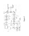
Figure 2 is a drawing that schematically shows optical system for experiment according to an example of the present invention. -
Figure 3 is a drawing that shows a space profile for an excited optical vortex (L=1) according to example 1. -
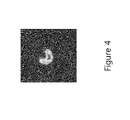
Figure 4 is a drawing that shows a space profile for signal light according to example 1. -
Figure 5 is a drawing that shows a space profile for idler light according to example 1. -
Figure 6 is a drawing that shows a space profile for signal light (L=1) emitted from a SHG unit in example 1. -
Figure 7 is a drawing that shows a space profile for idler light (L=1) emitted from a SHG unit in example 1. -
Figure 8 is a drawing that shows a space profile for signal light emitted from an interference unit in example 1. -
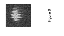
Figure 9 is a drawing that shows a space profile for idler light emitted from an interference unit in example 1. -
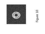
Figure 10 is a drawing that shows a space profile for an excited optical vortex according to example 2. -
Figure 11 is a drawing that shows a space profile for signal light according to example 2. -
Figure 12 is a drawing that shows a space profile for idler light according to example 2. -
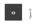
Figure 13 is a drawing that shows a space profile for signal light (L=1) emitted from a SHG unit in example 2. -
Figure 14 is a drawing that shows a space profile for idler light (L=1) emitted from a SHG unit in example 2. -
Figure 15 is a drawing that shows a space profile for signal light emitted from an interference unit in example 2. -
Figure 16 is a drawing that shows a space profile for idler light emitted from an interference unit in example 2. -
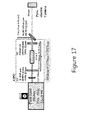
Figure 17 is a drawing that schematically shows optical system for experiment according to an example 3. -
Figure 18 is a drawing that shows input-output characteristics for an optical parametric generation according to example 3. -
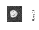
Figure 19 is a drawing that shows a space profile for signal light and idler light according to example 3. -
Figure 20 is a drawing that shows a primary diffracted light pattern after signal light and idler light pass through diffraction grating according to example 3. - Hereinafter, embodiments for carrying out the present invention are described in detail by drawings. However, the present invention may have several embodiments and may not be limited to embodiments and examples described below.
- An optical vortex laser oscillation device (hereinafter, referred to as "the present laser device") according to the present embodiment comprises a laser light source for generating laser light of pulse excitation, an optical vortex generation unit for generating an excited optical vortex based on the laser light generated by the laser light source, and an optical parametric oscillation system for generating a plurality of coherent optical vortices based on the excited optical vortex generated by the optical vortex generation unit and varying quantum number of orbital angular momentum to perform frequency conversion.
- The optical parametric oscillation system according to the present embodiment means an optical system that generates a plurality of coherent optical vortices based on the excited optical vortex generated by the optical vortex generation unit and that changes the quantum number of orbital angular momentum to perform frequency conversion. Configuration of the optical parametric oscillation system is not limited as far as its function is maintained. Specific example thereof may be an optical system that includes a pair of resonator mirrors and a medium sandwiched between the pair of resonator mirrors, i.e., an optical resonance unit. More specific example thereof is described below.
-
Figure 1 is a drawing that schematically shows an optical system of an optical vortex laser oscillation device (hereinafter, referred to as "the present laser device") according to the present embodiment. As shown infigure 1 , thepresent laser device 1 includes alaser light source 2 for generating laser light B1, an opticalvortex generation unit 3 for generating an excited optical vortex B2 based on the laser light B1 which thelaser light source 2 generates, and an optical resonance unit 4 for resonating the excited optical vortex B2 which the optical vortex generation unit generates and for dividing the excited optical vortex B2 into signal light and idler light. - In the present embodiment, the
laser light source 2 can generate the laser light B1 described above. Thelaser light source 2 is not limited as far as the above mentioned function is maintained. Examples thereof include a solid-state laser such as YAG laser, a dye laser, a gas laser such as He-Ne laser, a semiconductor laser such as LD laser, and the like. Wavelength region of light emitted from thelaser light source 2 in the present embodiment is preferably in the outside range of visible region. Wavelength region of emitted light is preferably 800 nm or more, and more preferably 1000 nm or more. Within this wavelength region, it is possible to obtain light from visible wavelength region to middle infrared region in the optical resonance unit 4. - Furthermore, in the present embodiment, the
laser light source 2 is preferably a pulse oscillation laser light source for generating pulse laser light. The pulse oscillation laser light source has wider spectral width than a continuous oscillation laser light source. The pulse oscillation laser light source is applicable because it emits high power laser light. Coherent coupling is difficult to occur in the continuous oscillation laser light source, whereas coherent coupling is easy to occur in the pulse oscillation laser light source. - Furthermore, in the present embodiment, the optical
vortex generation unit 3 can generate the excited optical vortex B2 based on the laser light B1 which thelaser light source 2 generates. The opticalvortex generation unit 3 is not limited and may use a phase plate, a space phase modulator, a multi-mode area fiber amplifier, or the like. Furthermore, configuration in which thelaser light source 2 and the opticalvortex generation unit 3 are directly united to generate an optical vortex may be employed. The optical vortex generated by the opticalvortex generation unit 3 is more preferably a coherent optical vortex. - Furthermore, in the present embodiment, the optical resonance unit 4 can resonate the excited optical vortex B2 generated by the optical vortex generation unit and generate a plurality of coherent optical vortices, and change quantum number of orbital angular momentum to perform frequency conversion. Specifically, it is possible to divide into signal light and idler light. Furthermore, an optical vortex generated from an optical parametric oscillation system (an optical resonance unit) according to the present embodiment can arbitrarily change quantum number of starting angular momentum by varying resonance condition, thereby enabling the plurality of quantum number of light to be a degenerate state, and also to be a non-degenerate state.
- In the present embodiment, the optical resonance unit 4 is not limited. For example, the optical resonance unit 4 preferably includes a
non-linear medium 41 and a pair of resonator mirrors 42 sandwiching thenon-linear medium 41. - In the present embodiment, wavelength of light emitted from the optical resonance unit 4 is not limited. Light having from visible wavelength region to middle infrared region (wavelength region having 360 nm or more and 4µm or less) is preferable. Wavelength variable region thereof is preferably 1.5 times greater than and 2.5 times less than wavelength of the excited optical vortex, more preferably 1.8 times greater than and 2.2 times less than wavelength of the excited optical vortex. Wavelength of light emitted from the optical resonance unit 4 may be the same or different from one another. In the case where the wavelength of light is different from one another, multi-frequency occurs and thus difference frequency can be generated.
- In the present embodiment, the
non-linear medium 41 is used for adjusting optical path length in the resonator, and not limited as far as function thereof is maintained. For example, the non-linear medium 41 preferably includes at least any one of KTiOPO4, periodically polarization-reversed LINbO3, and periodically polarization-reversed LiTaO3. - In the present embodiment, the pair of
mirrors 42 in which emitted light is partially transmitted and emitted light is partially reflected is designed to have high reflectivity in opposite surfaces. Light is confined with high reflectivity by reflection of light, thereby performing resonance of light. - In the present embodiment, configuration of the pair of resonator mirrors 42 is not limited as far as the above mentioned condition is maintained, and may have mirrors in which opposite surfaces are concave surfaces, one of the pair of resonator mirrors 42 is flat surface, or the pair of resonator mirrors 42 is a flat surface (i.e., parallel plate). In the case where concave surface is employed in the pair of resonator mirrors 42, radius of curvature thereof needs not to rotate Gouy phase and preferably sufficiently longer than resonance length formed by the pair of resonator mirrors 42. The radius of curvature is preferably at least 5 times larger than the resonance length, and more preferably 10 times larger than the resonance length.
- In the present embodiment, sum of energy of the excited optical vortex B2 and energies of signal light and idler light is equal to sum of momentum of the excited optical vortex B2 and momentums of signal light and idler light. Thus, the excited optical vortex can be divided into signal light and idler light. Herein, "equal" means complete matching and covers errors in experimental measurement or in setting of device. For example, equal includes errors having 2% or less in energy and momentum.
- In the present embodiment, a ratio of photon energy of idler light with respect to photon energy of signal light is 0.8 or more and 1.2 or less. Quantum numbers of signal light and idler light are divided so as to be within this range. For example, when quantum number of the excited optical vortex is two and photon energy of signal light is equal to photon energy of idler light, quantum numbers of signal light and idler light are identical and become one.
- In the present embodiment, distance between the pair of resonator mirrors 42 is not limited as far as it has sufficient length which is capable of sandwiching the non-linear medium and Gouy phase is not inverted. The distance thereof is preferably 3 cm or more and 10 cm or less.
- A laser oscillation device according to the present embodiment can change a state of emitted light by properly adjusting resonance condition of the optical resonator 4. For example, the adjusting methods include modifications of the distance between the pair of resonator mirrors 42, radius of curvature for at least one resonator, and material, temperature, direction (i.e., rotation position), and the like of the non-linear medium formed between the pair of resonator mirrors 42.
- Furthermore, as clearly shown in the above mentioned configuration, provided is a laser generation method that generates an modulated optical vortex by configuring an optical vortex laser oscillation device according to the present embodiment, for example, by irradiating an optical vortex of pulse excitation into an optical parametric oscillation system, generating a plurality of coherent optical vortices, and changing quantum number of orbital angular momentum to perform frequency conversion, more specifically by generating laser light, generating an excited optical vortex based on the generated laser light, and resonating the excited optical vortex.
- Hereinabove, the optical vortex oscillation device according to the present embodiment can have a high power and generate an optical vortex that divides quantum number into a wide range of frequency.
- Herein, an optical vortex laser oscillation device according to the embodiment described above was fabricated and effects thereof were confirmed. Hereinafter, details are described.
-
Figure 2 is a drawing that shows optical system for experiment according to the example 1. In the example 1, the configuration described in the above mentioned embodiment further includes experimental system for confirming quantum number of emitted light and the like. - As shown in
figure 2 , the present experimental optical system S includes alaser light source 2 for generating laser light B1, an opticalvortex generation unit 3 for generating an excited optical vortex based on the laser light B1 which thelaser light source 2 generates, and an optical resonance unit 4 for resonating the excited optical vortex B2 which the opticalvortex generation unit 3 generates and dividing the excited optical vortex B2 into signal light and idler light. - As the
laser light source 2 in the example 1, Nd:YAG (Lotis SL-2136, 1064 nm of wavelength, 40 ns of pulse width, 50 Hz of repetition speed) was used. - Furthermore, in the example 1, a helical phase plate was used for the optical
vortex generation unit 3 and was configured to generate an excited optical vortex of quantum number of L=1. In thefigure 3 , a space profile of the excited optical vortex in this state is shown. - Furthermore, in the example 1, a first plane reflection mirror (98% of reflectance for 2µm and 90% of transmittance for 1 µm) and a second plane reflection mirror (100% of transmittance for 2 µm and 80% of reflectance for 1 µm) were used for the optical resonance unit 4. The optical resonance unit 4 is configured that the distance (i.e., resonator length) between the first plane reflection mirror and the second reflection mirror was 5 cm and that KTiOPO4 (θ=51.4°) of a non-linear medium with 5 mm X 5 mm X 30 mm was formed therebetween.
- In the present experimental optical system S, emitted light from the optical resonance unit 4 was reflected by a mirror and then passed through a half wavelength plate. Thereafter, signal light and idler light can be respectively emitted by a first polarization beam splitter PBS. The light passing through the first polarization beam splitter is irradiated into a SHG unit 5 and an interference unit 6 described later. In
figures 4 and5 , space profiles for the signal light and the idler light emitted from the first polarization beam splitter are shown. - In the present experimental optical system S, a SHG unit 5 and an interference unit 6 are prepared. The SHG unit 5 is a unit for generating SHG light and can generate light with twice as many frequencies as light generated by the optical
vortex generation unit 3. The SHG unit 5 includes a first lens (f=100 mm), a second lens (f=100 mm), and KTiOPO4 (θ=51.4°) of a non-linear medium with 10 mm X 10 mm X 20 mm, wherein the KTiOPO4 is formed between the first lens and the second lens. - In the example 1, the interference unit 6 is also prepared and is a unit that performs interference with respect to light emitted from the SHG unit 5. By the interference unit 6, quantum numbers of the signal light and the idler light can be confirmed. Furthermore, in the example 1, the interference unit 6 includes a first half mirror (50% of reflectance), a first total reflection mirror that reflects one of lights being reflected by the first half mirror, a second total reflection mirror that reflects the other of lights being transmitted by the first half mirror, and a second half mirror for adjusting light reflected by the first total reflection mirror and the second total reflection mirror.
- In the present experimental optical system S, a second polarization beam splitter PBS is formed between the SHG unit 5 and the interference unit 6, wherein one of polarized lights is irradiated into outside of the optical system S and the other of polarized lights is irradiated into the interference unit 6. In
figures 6 and7 , each space profile of the signal light and the idler light is shown, wherein the light is emitted from the SHG unit 5 and is not yet irradiated into the interference unit 7. Infigures 8 and9 , each space profile of the signal light and the idler light emitted from the interference unit 6 is shown. - As a result, it was confirmed that the signal light of ordinary ray after oscillation became 2µm of an optical vortex having L=0.5 and a space profile. That is to say, in the example 1, it was also confirmed that an optical vortex having arbitrary quantum number was can be generated, even in a middle infrared wavelength region, because half of quantum number which excited light has can be transcribed into the signal light after wavelength conversion, no optical vortex so far having been generated in a middle infrared wavelength region.
- The example 2 is similar to the example 1 except that two pieces of helical phase plates were used for an optical
vortex generation unit 3. By this configuration, it is possible to generate an excited optical vortex of L=2 of quantum number. - In
figure 10 , a space profile of the excited optical vortex before irradiation is shown. Infigures 11 and12 , space profiles for the signal light and the idler light emitted from the first polarization beam splitter are shown. Infigures 13 and14 , space profiles for the signal light and idler light emitted from the second polarization beam splitter PBS are shown. Infigures 15 and16 , space profiles for the signal light and the idler light emitted from the interference unit 6 are shown. - As a result, it was confirmed that an optical vortex of 2µm of L=1 of quantum number was generated. In this case, the optical vortex was not expressed in extraordinary ray. That is to say, in the example 2, it was confirmed that an optical vortex having arbitrary quantum number was can be generated, even in a middle infrared wavelength region, because half of quantum number which excited light has can be transcribed into the signal light after wavelength conversion, no optical vortex so far having been generated in a middle infrared wavelength region.
- The example 3 was similar to the example 1 except that pulse width of laser light which the
laser light source 2 generates was 25 nm, a first concave surface reflection mirror (R=2,000 mm, 98% of reflectance in 2 µm, 90% of transmittance in 1 µm) and a second flat surface reflection mirror (80% of reflectance in 2 µm, 80% of transmittance in 1 µm) were configured with opposite directions wherein distance (i.e., resonator length) therebetween was 31.2 mm, and PPSLT of a non-linear medium with 2mm X 2 mm X 30 mm was formed therebetween. As a result, light of 1064 nm was divided into light of 1970 nm and light of 2313 nm. - In
figure 17 , configuration of the optical system is shown. Infigure 18 , input-output characteristics of the optical parametric generation is shown. Moreover, infigure 19 , space profiles of signal light and idler light emitted from the optical resonance unit are shown. Infigure 20 , primary diffracted order optical patterns after each of signal light and idler light passed through a diffraction grating are shown. - As a result, by using hologram for a primary optical vortex with respect to the signal light and the idler light, diffracted light was irradiated thereto and diffracted light was obtained, whereby asymmetry occurred in intensity distribution. That is to say, it was known that orbital angular momentums of the signal light and the idler light are non-degenerate states. However, it was confirmed that symmetry occurred in intensity distribution and orbital angular momentums are degenerate states with respect to orbital angular momentums of the signal light and the idler light shown in the example 1.
- Hereinabove, according to the present invention, an optical vortex laser oscillation device can be provided, the optical vortex laser oscillation device being capable of high power and generating an optical vortex even in wide frequency range and if the optical vortex is quantum number which is not an integer. Especially, it is possible to generate multi-frequency by varying resonance condition and it is also possible to arbitrarily adjust any one of a degenerate state and a non-degenerate state.
- The present invention is industrially applicable as an optical vortex oscillation device and a method for generating an optical vortex laser.
Claims (27)
- A method for oscillating an optical vortex laser comprises: irradiating an optical vortex of pulse excitation into an optical parametric oscillation system; generating a plurality of coherent optical vortices; and varying quantum number of orbital angular momentum to perform frequency conversion.
- The method according to claim 1,
wherein the optical parametric oscillation system comprises a resonator that includes a non-linear medium and a pair of resonator mirrors sandwiching the non-linear medium. - The method according to claim 2,
wherein radius of curvature for the resonator mirrors is five times larger than resonator length formed by the pair of resonator mirrors. - The method according to claim 1,
wherein the pair of resonator mirrors is a parallel flat plate. - The method according to claim 1,
wherein a degenerate state of the quantum number of angular momentum is varied by changing resonance condition in the resonator. - The method according to claim 1,
wherein the quantum number of orbital angular momentum is a non-degenerate state. - The method according to claim 1,
wherein multi-frequency is generated by generating the plurality of coherent optical vortices. - The method according to claim 7,
wherein difference frequency is generated. - The method according to claim 2,
wherein the non-linear medium is rotated. - The method according to claim 2,
wherein temperature for the non-linear medium is changed. - The method according to claim 2,
wherein the non-linear medium includes at least any one of KTiOPO4, periodically polarization-reversed LiNbO3, and periodically polarization-reversed LiTaO3. - An optical vortex laser oscillation device comprises:a laser light source for generating laser light of pulse excitation;an optical vortex generation unit for generating an excited optical vortex based on the laser light generated by the laser light source; andan optical parametric oscillation system in which a plurality of coherent optical vortices are generated based on the excited optical vortex generated by the optical vortex generation unit and quantum number of orbital angular momentum is changed by performing frequency conversion.
- The optical vortex laser oscillation device according to claim 12,
wherein the optical parametric oscillation system comprises a resonator that includes a non-linear medium and a pair of resonator mirrors sandwiching the non-liner medium. - The optical vortex laser oscillation device according to claim 13,
wherein radius of curvature for the resonator mirrors is five times larger than resonator length formed by the pair of resonator mirrors. - The optical vortex laser oscillation device according to claim 12,
wherein the pair of resonator mirrors is a parallel flat plate. - The optical vortex laser oscillation device according to claim 12,
wherein a degenerate state of the quantum number of angular momentum is varied by changing resonance condition in the resonator. - The optical vortex laser oscillation device according to claim 12,
wherein the quantum number of orbital angular momentum is a non-degenerate state. - The optical vortex laser oscillation device according to claim 12,
wherein multi-frequency is generated by generating the plurality of coherent optical vortices. - The optical vortex laser oscillation device according to claim 18,
wherein difference frequency is generated. - The optical vortex laser oscillation device according to claim 13,
wherein the non-linear medium is rotated. - The optical vortex laser oscillation device according to claim 13,
wherein temperature for the non-linear medium is changed. - The optical vortex laser oscillation device according to claim 13,
wherein the non-linear medium includes at least any one of KTiOPO4, periodically polarization-reversed LiNbO3, and periodically polarization-reversed LiTaO3. - A laser oscillation device comprises:a laser light source for generating laser light;an optical vortex generation unit for generating an excited optical vortex based on the laser light generated by the laser light source; and,an optical resonance unit for resonating the excited optical vortex generated by the optical vortex generation unit and dividing the excited optical vortex into signal light and idler light.
- The laser oscillation device according to claim 23,
wherein the optical resonance unit includes a non-linear medium and a pair of resonator mirrors sandwiching the non-liner medium. - The laser oscillation device according to claim 24,
wherein radius of curvature for the resonator mirrors is five times larger than resonator length formed by the pair of resonator mirrors. - The laser oscillation device according to claim 23,
wherein a ratio of photon energy for the idler light with respect to photon energy for the signal light is 0.8 or more and 1.2 or less. - The laser oscillation device according to claim 24,
wherein the non-linear medium includes at least any one of KTiOPO4, periodically polarization-reversed LiNbO3, and periodically polarization-reversed LiTaO3.
Applications Claiming Priority (2)
| Application Number | Priority Date | Filing Date | Title |
|---|---|---|---|
| JP2011127356 | 2011-06-07 | ||
| PCT/JP2012/064663 WO2012169578A2 (en) | 2011-06-07 | 2012-06-07 | Optical vortex laser vibration method and optical vortex laser vibration device |
Publications (3)
| Publication Number | Publication Date |
|---|---|
| EP2706406A2 true EP2706406A2 (en) | 2014-03-12 |
| EP2706406A4 EP2706406A4 (en) | 2014-04-16 |
| EP2706406B1 EP2706406B1 (en) | 2016-09-21 |
Family
ID=47296550
Family Applications (1)
| Application Number | Title | Priority Date | Filing Date |
|---|---|---|---|
| EP12796232.2A Not-in-force EP2706406B1 (en) | 2011-06-07 | 2012-06-07 | Optical vortex laser vibration method and optical vortex laser vibration device |
Country Status (4)
| Country | Link |
|---|---|
| US (1) | US9172205B2 (en) |
| EP (1) | EP2706406B1 (en) |
| JP (1) | JP6103597B2 (en) |
| WO (1) | WO2012169578A2 (en) |
Cited By (2)
| Publication number | Priority date | Publication date | Assignee | Title |
|---|---|---|---|---|
| CN104007567A (en) * | 2014-06-12 | 2014-08-27 | 北京邮电大学 | Method of vortex light beam generating system with tunable orbital angular momentum state |
| CN109375233A (en) * | 2018-10-31 | 2019-02-22 | 江苏蓝缕机电液体化科技有限公司 | A kind of laser range finder based on light track angular momentum spatial reuse |
Families Citing this family (16)
| Publication number | Priority date | Publication date | Assignee | Title |
|---|---|---|---|---|
| US10099921B2 (en) | 2013-05-10 | 2018-10-16 | National University Corporation Chiba University | Method for producing organic helical structure, and organic helical structure produced using said method |
| US10138269B2 (en) | 2014-08-31 | 2018-11-27 | National University Corporation Chiba University | Method for producing amino acid crystals and method for producing protein crystals |
| CN107635779B (en) * | 2015-02-25 | 2019-12-13 | 株式会社理光 | Light-absorbing material spraying device, light-absorbing material spraying method, and applications using the same |
| JP6658762B2 (en) * | 2015-10-06 | 2020-03-04 | 株式会社リコー | Image forming method, image forming apparatus, laser irradiation recording ink, and method of manufacturing image formed product |
| JP6982817B2 (en) * | 2016-08-31 | 2021-12-17 | 国立大学法人千葉大学 | Chiral microfiber manufacturing method and chiral microfiber manufactured by this method |
| JP7199669B2 (en) * | 2017-11-16 | 2023-01-06 | 国立大学法人長岡技術科学大学 | Light-generating device, exposure apparatus provided with light-generating device, exposure system, light-generating method, and exposure photoresist manufacturing method |
| US10439287B2 (en) * | 2017-12-21 | 2019-10-08 | Nxgen Partners Ip, Llc | Full duplex using OAM |
| TWI651906B (en) * | 2018-06-08 | 2019-02-21 | 國立中山大學 | Spiral phase modulation resonant cavity vortex laser light generator and method for generating vortex laser light |
| US12038525B2 (en) * | 2018-07-16 | 2024-07-16 | Or-Ment Llc | Electromagnetic wave medical imaging system, device and methods |
| US10670391B2 (en) * | 2018-10-26 | 2020-06-02 | Northrop Grumman Systems Corporation | Confocal optical protractor |
| CN112736632B (en) * | 2019-10-28 | 2025-03-21 | 中国科学院上海光学精密机械研究所 | Structured light laser with built-in diffraction lens |
| CN111200233A (en) * | 2020-01-15 | 2020-05-26 | 厦门大学 | Narrow linewidth frequency multiplication vortex optical laser |
| CN112612142B (en) * | 2020-12-31 | 2024-07-02 | 华中科技大学 | Optical system for generating quasi-flat-top round light spot |
| CN114184285B (en) * | 2021-10-27 | 2023-04-18 | 西安石油大学 | Vortex optical topological charge number detection device based on nonlinear medium |
| CN114236942A (en) * | 2021-11-29 | 2022-03-25 | 南京大学 | System and method for generating forecast single photon carrying orbital angular momentum |
| CN115236787B (en) * | 2022-08-12 | 2023-05-16 | 浙江师范大学 | Multi-spiral phase mask plate, multi-spiral light beam generation method and light modulator |
Family Cites Families (3)
| Publication number | Priority date | Publication date | Assignee | Title |
|---|---|---|---|---|
| FR2758893B1 (en) * | 1997-01-24 | 1999-04-16 | Onera (Off Nat Aerospatiale) | SINGLE-MODE PULSED OPTICAL PARAMETRIC OSCILLATOR |
| US7050469B1 (en) * | 2003-08-14 | 2006-05-23 | Ionatron | Generation of optical filaments by use of phase plate |
| US7620077B2 (en) * | 2005-07-08 | 2009-11-17 | Lockheed Martin Corporation | Apparatus and method for pumping and operating optical parametric oscillators using DFB fiber lasers |
-
2012
- 2012-06-07 JP JP2013519522A patent/JP6103597B2/en active Active
- 2012-06-07 EP EP12796232.2A patent/EP2706406B1/en not_active Not-in-force
- 2012-06-07 WO PCT/JP2012/064663 patent/WO2012169578A2/en not_active Ceased
- 2012-06-07 US US14/124,409 patent/US9172205B2/en not_active Expired - Fee Related
Non-Patent Citations (7)
| Title |
|---|
| BOVINO F A ET AL: "Management of the orbital angular momentum of vortex beams in a quadratic nonlinear interaction", OPTICS COMMUNICATIONS, NORTH-HOLLAND PUBLISHING CO. AMSTERDAM, NL, vol. 284, no. 10, 19 January 2011 (2011-01-19), pages 2587-2593, XP028169385, ISSN: 0030-4018, DOI: 10.1016/J.OPTCOM.2011.01.051 [retrieved on 2011-01-27] * |
| COUTINHO DOS SANTOS B ET AL: "Transfer of orbital angular momentum in a multimode parametric oscillator", OPTICS LETTERS, OPTICAL SOCIETY OF AMERICA, US, vol. 33, no. 23, 1 December 2008 (2008-12-01), pages 2803-2805, XP001521010, ISSN: 0146-9592, DOI: 10.1364/OL.33.002803 * |
| J. ARLT ET AL: "Parametric down-conversion for light beams possessing orbital angular momentum", PHYSICAL REVIEW A, vol. 59, no. 5, 23 September 1998 (1998-09-23), pages 3950-3952, XP055107047, ISSN: 1050-2947, DOI: 10.1103/PhysRevA.59.3950 * |
| K. DHOLAKIA ET AL: "Second-harmonic generation and the orbital angular momentum of light", PHYSICAL REVIEW A, vol. 54, no. 5, 15 July 1996 (1996-07-15), pages R3742-R3745, XP055107058, ISSN: 1050-2947, DOI: 10.1103/PhysRevA.54.R3742 * |
| KIVSHARAND Y S ET AL: "OPTICAL VORTICES FOLDING AND TWISTING WAVES OF LIGHT", OPTICS AND PHOTONICS NEWS, OSA, WASHINGTON, DC, US, vol. 12, no. 4, 1 April 2001 (2001-04-01), pages 24-29, XP001173025, ISSN: 1047-6938 * |
| See also references of WO2012169578A2 * |
| YI-XIN ZHANG ET AL: "Orbital angular momentum crosstalk of single photons propagation in a slant non-Kolmogorov turbulence channel", OPTICS COMMUNICATIONS, vol. 284, no. 5, 1 March 2011 (2011-03-01) , pages 1132-1138, XP055107141, ISSN: 0030-4018, DOI: 10.1016/j.optcom.2010.10.077 * |
Cited By (4)
| Publication number | Priority date | Publication date | Assignee | Title |
|---|---|---|---|---|
| CN104007567A (en) * | 2014-06-12 | 2014-08-27 | 北京邮电大学 | Method of vortex light beam generating system with tunable orbital angular momentum state |
| CN104007567B (en) * | 2014-06-12 | 2017-02-15 | 北京邮电大学 | Vortex light beam generating system with tunable orbital angular momentum state |
| CN109375233A (en) * | 2018-10-31 | 2019-02-22 | 江苏蓝缕机电液体化科技有限公司 | A kind of laser range finder based on light track angular momentum spatial reuse |
| CN109375233B (en) * | 2018-10-31 | 2021-03-30 | 江苏蓝缕机电液一体化科技有限公司 | Laser range finder based on optical orbital angular momentum spatial multiplexing |
Also Published As
| Publication number | Publication date |
|---|---|
| US9172205B2 (en) | 2015-10-27 |
| EP2706406A4 (en) | 2014-04-16 |
| EP2706406B1 (en) | 2016-09-21 |
| JPWO2012169578A1 (en) | 2015-02-23 |
| JP6103597B2 (en) | 2017-03-29 |
| WO2012169578A3 (en) | 2013-01-31 |
| WO2012169578A2 (en) | 2012-12-13 |
| US20140226685A1 (en) | 2014-08-14 |
Similar Documents
| Publication | Publication Date | Title |
|---|---|---|
| US9172205B2 (en) | Method for oscillating an optical vortex laser and optical vortex laser oscillation device | |
| US10809594B2 (en) | Kind of visible ultraviolet band optical frequency converter | |
| JP5035803B2 (en) | Optical vortex laser beam oscillation method and optical vortex laser beam oscillation apparatus | |
| KR20150129021A (en) | Highly Efficient, Single-Pass, Harmonic Generator with Round Output Beam | |
| EP3186679B1 (en) | Method and device for cavity-enhanced broadband intrapulse difference frequency generation | |
| JP6718779B2 (en) | Wavelength conversion element and wavelength conversion optical pulse waveform shaping device | |
| CN105742944B (en) | A kind of dual wavelength, narrow linewidth terahertz-wave parametric oscillator | |
| CN118315902B (en) | An ultrafast time-delay wavelength scanning ultraviolet femtosecond laser pulse train generator | |
| Donin et al. | New method of Q-switching with mode locking in solid-state lasers | |
| CN106340797B (en) | 2 μm of tunable laser of annular chamber optical parametric oscillator are constituted based on body grating | |
| Kolker et al. | A nanosecond optical parametric oscillator in the mid-IR region with double-pass pump | |
| CN101752778A (en) | Double-cavity resonating device and method for generating self-synchronizing femtosecond pulse and picosecond pulse | |
| WO2014141266A1 (en) | Tunable nonlinear beam shaping by a non-collinear interaction | |
| CN106451051B (en) | 2 μm of tunable laser of standing-wave cavity optical parametric oscillator are constituted based on body grating | |
| CN102097741B (en) | 532nm semi-Gaussian laser beam generator | |
| CN118841819B (en) | Low-noise 569nm wavelength all-solid-state yellow-green laser and generation method | |
| CN111313221A (en) | A laser that directly generates two-way coherent light | |
| Sharma et al. | Direct generation of tunable optical vortex dipole beams using a Gaussian beam pumped optical parametric oscillator | |
| JP2011197349A (en) | Pseudo phase matching element and laser device including the same | |
| Widarsson | Blue-UV generation through Intra-Cavity Sum Frequency Generation | |
| Sharma et al. | Optical vortex generation from an anti-resonant-ring picosecond optical parametric oscillator | |
| US20090219956A1 (en) | Device for Generating Narrowband Optical Radiation | |
| Sharma et al. | Tunable, vortex dipole doubly resonant optical parametric oscillator | |
| Sharma et al. | Generation of vector vortex beam from doubly-resonant nanosecond optical parametric oscillator | |
| JP2016119363A (en) | Mode-locked laser device and measurement device |
Legal Events
| Date | Code | Title | Description |
|---|---|---|---|
| PUAI | Public reference made under article 153(3) epc to a published international application that has entered the european phase |
Free format text: ORIGINAL CODE: 0009012 |
|
| 17P | Request for examination filed |
Effective date: 20131202 |
|
| AK | Designated contracting states |
Kind code of ref document: A2 Designated state(s): AL AT BE BG CH CY CZ DE DK EE ES FI FR GB GR HR HU IE IS IT LI LT LU LV MC MK MT NL NO PL PT RO RS SE SI SK SM TR |
|
| A4 | Supplementary search report drawn up and despatched |
Effective date: 20140319 |
|
| RIC1 | Information provided on ipc code assigned before grant |
Ipc: H01S 3/10 20060101ALI20140313BHEP Ipc: G02F 1/39 20060101AFI20140313BHEP |
|
| DAX | Request for extension of the european patent (deleted) | ||
| 17Q | First examination report despatched |
Effective date: 20150316 |
|
| GRAP | Despatch of communication of intention to grant a patent |
Free format text: ORIGINAL CODE: EPIDOSNIGR1 |
|
| INTG | Intention to grant announced |
Effective date: 20160316 |
|
| GRAR | Information related to intention to grant a patent recorded |
Free format text: ORIGINAL CODE: EPIDOSNIGR71 |
|
| GRAS | Grant fee paid |
Free format text: ORIGINAL CODE: EPIDOSNIGR3 |
|
| GRAA | (expected) grant |
Free format text: ORIGINAL CODE: 0009210 |
|
| INTC | Intention to grant announced (deleted) | ||
| AK | Designated contracting states |
Kind code of ref document: B1 Designated state(s): AL AT BE BG CH CY CZ DE DK EE ES FI FR GB GR HR HU IE IS IT LI LT LU LV MC MK MT NL NO PL PT RO RS SE SI SK SM TR |
|
| INTG | Intention to grant announced |
Effective date: 20160817 |
|
| REG | Reference to a national code |
Ref country code: GB Ref legal event code: FG4D |
|
| REG | Reference to a national code |
Ref country code: CH Ref legal event code: EP |
|
| REG | Reference to a national code |
Ref country code: AT Ref legal event code: REF Ref document number: 831518 Country of ref document: AT Kind code of ref document: T Effective date: 20161015 |
|
| REG | Reference to a national code |
Ref country code: IE Ref legal event code: FG4D |
|
| REG | Reference to a national code |
Ref country code: DE Ref legal event code: R096 Ref document number: 602012023338 Country of ref document: DE |
|
| REG | Reference to a national code |
Ref country code: LT Ref legal event code: MG4D Ref country code: NL Ref legal event code: MP Effective date: 20160921 |
|
| PG25 | Lapsed in a contracting state [announced via postgrant information from national office to epo] |
Ref country code: RS Free format text: LAPSE BECAUSE OF FAILURE TO SUBMIT A TRANSLATION OF THE DESCRIPTION OR TO PAY THE FEE WITHIN THE PRESCRIBED TIME-LIMIT Effective date: 20160921 Ref country code: NO Free format text: LAPSE BECAUSE OF FAILURE TO SUBMIT A TRANSLATION OF THE DESCRIPTION OR TO PAY THE FEE WITHIN THE PRESCRIBED TIME-LIMIT Effective date: 20161221 Ref country code: LT Free format text: LAPSE BECAUSE OF FAILURE TO SUBMIT A TRANSLATION OF THE DESCRIPTION OR TO PAY THE FEE WITHIN THE PRESCRIBED TIME-LIMIT Effective date: 20160921 Ref country code: FI Free format text: LAPSE BECAUSE OF FAILURE TO SUBMIT A TRANSLATION OF THE DESCRIPTION OR TO PAY THE FEE WITHIN THE PRESCRIBED TIME-LIMIT Effective date: 20160921 |
|
| REG | Reference to a national code |
Ref country code: AT Ref legal event code: MK05 Ref document number: 831518 Country of ref document: AT Kind code of ref document: T Effective date: 20160921 |
|
| PG25 | Lapsed in a contracting state [announced via postgrant information from national office to epo] |
Ref country code: NL Free format text: LAPSE BECAUSE OF FAILURE TO SUBMIT A TRANSLATION OF THE DESCRIPTION OR TO PAY THE FEE WITHIN THE PRESCRIBED TIME-LIMIT Effective date: 20160921 Ref country code: LV Free format text: LAPSE BECAUSE OF FAILURE TO SUBMIT A TRANSLATION OF THE DESCRIPTION OR TO PAY THE FEE WITHIN THE PRESCRIBED TIME-LIMIT Effective date: 20160921 Ref country code: SE Free format text: LAPSE BECAUSE OF FAILURE TO SUBMIT A TRANSLATION OF THE DESCRIPTION OR TO PAY THE FEE WITHIN THE PRESCRIBED TIME-LIMIT Effective date: 20160921 Ref country code: GR Free format text: LAPSE BECAUSE OF FAILURE TO SUBMIT A TRANSLATION OF THE DESCRIPTION OR TO PAY THE FEE WITHIN THE PRESCRIBED TIME-LIMIT Effective date: 20161222 |
|
| PG25 | Lapsed in a contracting state [announced via postgrant information from national office to epo] |
Ref country code: RO Free format text: LAPSE BECAUSE OF FAILURE TO SUBMIT A TRANSLATION OF THE DESCRIPTION OR TO PAY THE FEE WITHIN THE PRESCRIBED TIME-LIMIT Effective date: 20160921 Ref country code: EE Free format text: LAPSE BECAUSE OF FAILURE TO SUBMIT A TRANSLATION OF THE DESCRIPTION OR TO PAY THE FEE WITHIN THE PRESCRIBED TIME-LIMIT Effective date: 20160921 |
|
| PG25 | Lapsed in a contracting state [announced via postgrant information from national office to epo] |
Ref country code: AT Free format text: LAPSE BECAUSE OF FAILURE TO SUBMIT A TRANSLATION OF THE DESCRIPTION OR TO PAY THE FEE WITHIN THE PRESCRIBED TIME-LIMIT Effective date: 20160921 Ref country code: CZ Free format text: LAPSE BECAUSE OF FAILURE TO SUBMIT A TRANSLATION OF THE DESCRIPTION OR TO PAY THE FEE WITHIN THE PRESCRIBED TIME-LIMIT Effective date: 20160921 Ref country code: BG Free format text: LAPSE BECAUSE OF FAILURE TO SUBMIT A TRANSLATION OF THE DESCRIPTION OR TO PAY THE FEE WITHIN THE PRESCRIBED TIME-LIMIT Effective date: 20161221 Ref country code: SM Free format text: LAPSE BECAUSE OF FAILURE TO SUBMIT A TRANSLATION OF THE DESCRIPTION OR TO PAY THE FEE WITHIN THE PRESCRIBED TIME-LIMIT Effective date: 20160921 Ref country code: IS Free format text: LAPSE BECAUSE OF FAILURE TO SUBMIT A TRANSLATION OF THE DESCRIPTION OR TO PAY THE FEE WITHIN THE PRESCRIBED TIME-LIMIT Effective date: 20170121 Ref country code: SK Free format text: LAPSE BECAUSE OF FAILURE TO SUBMIT A TRANSLATION OF THE DESCRIPTION OR TO PAY THE FEE WITHIN THE PRESCRIBED TIME-LIMIT Effective date: 20160921 Ref country code: PT Free format text: LAPSE BECAUSE OF FAILURE TO SUBMIT A TRANSLATION OF THE DESCRIPTION OR TO PAY THE FEE WITHIN THE PRESCRIBED TIME-LIMIT Effective date: 20170123 Ref country code: BE Free format text: LAPSE BECAUSE OF FAILURE TO SUBMIT A TRANSLATION OF THE DESCRIPTION OR TO PAY THE FEE WITHIN THE PRESCRIBED TIME-LIMIT Effective date: 20160921 Ref country code: PL Free format text: LAPSE BECAUSE OF FAILURE TO SUBMIT A TRANSLATION OF THE DESCRIPTION OR TO PAY THE FEE WITHIN THE PRESCRIBED TIME-LIMIT Effective date: 20160921 Ref country code: ES Free format text: LAPSE BECAUSE OF FAILURE TO SUBMIT A TRANSLATION OF THE DESCRIPTION OR TO PAY THE FEE WITHIN THE PRESCRIBED TIME-LIMIT Effective date: 20160921 |
|
| REG | Reference to a national code |
Ref country code: DE Ref legal event code: R097 Ref document number: 602012023338 Country of ref document: DE |
|
| PG25 | Lapsed in a contracting state [announced via postgrant information from national office to epo] |
Ref country code: IT Free format text: LAPSE BECAUSE OF FAILURE TO SUBMIT A TRANSLATION OF THE DESCRIPTION OR TO PAY THE FEE WITHIN THE PRESCRIBED TIME-LIMIT Effective date: 20160921 |
|
| PLBE | No opposition filed within time limit |
Free format text: ORIGINAL CODE: 0009261 |
|
| STAA | Information on the status of an ep patent application or granted ep patent |
Free format text: STATUS: NO OPPOSITION FILED WITHIN TIME LIMIT |
|
| PG25 | Lapsed in a contracting state [announced via postgrant information from national office to epo] |
Ref country code: DK Free format text: LAPSE BECAUSE OF FAILURE TO SUBMIT A TRANSLATION OF THE DESCRIPTION OR TO PAY THE FEE WITHIN THE PRESCRIBED TIME-LIMIT Effective date: 20160921 |
|
| 26N | No opposition filed |
Effective date: 20170622 |
|
| PG25 | Lapsed in a contracting state [announced via postgrant information from national office to epo] |
Ref country code: SI Free format text: LAPSE BECAUSE OF FAILURE TO SUBMIT A TRANSLATION OF THE DESCRIPTION OR TO PAY THE FEE WITHIN THE PRESCRIBED TIME-LIMIT Effective date: 20160921 |
|
| PG25 | Lapsed in a contracting state [announced via postgrant information from national office to epo] |
Ref country code: MC Free format text: LAPSE BECAUSE OF FAILURE TO SUBMIT A TRANSLATION OF THE DESCRIPTION OR TO PAY THE FEE WITHIN THE PRESCRIBED TIME-LIMIT Effective date: 20160921 |
|
| REG | Reference to a national code |
Ref country code: CH Ref legal event code: PL |
|
| REG | Reference to a national code |
Ref country code: IE Ref legal event code: MM4A |
|
| REG | Reference to a national code |
Ref country code: FR Ref legal event code: ST Effective date: 20180228 |
|
| PG25 | Lapsed in a contracting state [announced via postgrant information from national office to epo] |
Ref country code: CH Free format text: LAPSE BECAUSE OF NON-PAYMENT OF DUE FEES Effective date: 20170630 Ref country code: LU Free format text: LAPSE BECAUSE OF NON-PAYMENT OF DUE FEES Effective date: 20170607 Ref country code: IE Free format text: LAPSE BECAUSE OF NON-PAYMENT OF DUE FEES Effective date: 20170607 Ref country code: LI Free format text: LAPSE BECAUSE OF NON-PAYMENT OF DUE FEES Effective date: 20170630 |
|
| PG25 | Lapsed in a contracting state [announced via postgrant information from national office to epo] |
Ref country code: FR Free format text: LAPSE BECAUSE OF NON-PAYMENT OF DUE FEES Effective date: 20170630 |
|
| PG25 | Lapsed in a contracting state [announced via postgrant information from national office to epo] |
Ref country code: MT Free format text: LAPSE BECAUSE OF NON-PAYMENT OF DUE FEES Effective date: 20170607 |
|
| PG25 | Lapsed in a contracting state [announced via postgrant information from national office to epo] |
Ref country code: AL Free format text: LAPSE BECAUSE OF FAILURE TO SUBMIT A TRANSLATION OF THE DESCRIPTION OR TO PAY THE FEE WITHIN THE PRESCRIBED TIME-LIMIT Effective date: 20160921 |
|
| PG25 | Lapsed in a contracting state [announced via postgrant information from national office to epo] |
Ref country code: HU Free format text: LAPSE BECAUSE OF FAILURE TO SUBMIT A TRANSLATION OF THE DESCRIPTION OR TO PAY THE FEE WITHIN THE PRESCRIBED TIME-LIMIT; INVALID AB INITIO Effective date: 20120607 |
|
| PGFP | Annual fee paid to national office [announced via postgrant information from national office to epo] |
Ref country code: DE Payment date: 20190611 Year of fee payment: 8 |
|
| PG25 | Lapsed in a contracting state [announced via postgrant information from national office to epo] |
Ref country code: CY Free format text: LAPSE BECAUSE OF NON-PAYMENT OF DUE FEES Effective date: 20160921 |
|
| PGFP | Annual fee paid to national office [announced via postgrant information from national office to epo] |
Ref country code: GB Payment date: 20190620 Year of fee payment: 8 |
|
| PG25 | Lapsed in a contracting state [announced via postgrant information from national office to epo] |
Ref country code: MK Free format text: LAPSE BECAUSE OF FAILURE TO SUBMIT A TRANSLATION OF THE DESCRIPTION OR TO PAY THE FEE WITHIN THE PRESCRIBED TIME-LIMIT Effective date: 20160921 |
|
| PG25 | Lapsed in a contracting state [announced via postgrant information from national office to epo] |
Ref country code: TR Free format text: LAPSE BECAUSE OF FAILURE TO SUBMIT A TRANSLATION OF THE DESCRIPTION OR TO PAY THE FEE WITHIN THE PRESCRIBED TIME-LIMIT Effective date: 20160921 |
|
| PG25 | Lapsed in a contracting state [announced via postgrant information from national office to epo] |
Ref country code: HR Free format text: LAPSE BECAUSE OF FAILURE TO SUBMIT A TRANSLATION OF THE DESCRIPTION OR TO PAY THE FEE WITHIN THE PRESCRIBED TIME-LIMIT Effective date: 20160921 |
|
| REG | Reference to a national code |
Ref country code: DE Ref legal event code: R119 Ref document number: 602012023338 Country of ref document: DE |
|
| GBPC | Gb: european patent ceased through non-payment of renewal fee |
Effective date: 20200607 |
|
| PG25 | Lapsed in a contracting state [announced via postgrant information from national office to epo] |
Ref country code: GB Free format text: LAPSE BECAUSE OF NON-PAYMENT OF DUE FEES Effective date: 20200607 |
|
| PG25 | Lapsed in a contracting state [announced via postgrant information from national office to epo] |
Ref country code: DE Free format text: LAPSE BECAUSE OF NON-PAYMENT OF DUE FEES Effective date: 20210101 |