EP2706284A1 - System for mounting lighting devices and corresponding device - Google Patents
System for mounting lighting devices and corresponding device Download PDFInfo
- Publication number
- EP2706284A1 EP2706284A1 EP13181904.7A EP13181904A EP2706284A1 EP 2706284 A1 EP2706284 A1 EP 2706284A1 EP 13181904 A EP13181904 A EP 13181904A EP 2706284 A1 EP2706284 A1 EP 2706284A1
- Authority
- EP
- European Patent Office
- Prior art keywords
- jaws
- fixing member
- collar member
- pair
- annular fixing
- Prior art date
- Legal status (The legal status is an assumption and is not a legal conclusion. Google has not performed a legal analysis and makes no representation as to the accuracy of the status listed.)
- Granted
Links
- 230000015572 biosynthetic process Effects 0.000 claims description 7
- 238000005755 formation reaction Methods 0.000 claims description 7
- 230000008602 contraction Effects 0.000 claims description 4
- 230000005855 radiation Effects 0.000 description 6
- 210000002105 tongue Anatomy 0.000 description 5
- 230000000903 blocking effect Effects 0.000 description 2
- 230000000295 complement effect Effects 0.000 description 2
- 238000009434 installation Methods 0.000 description 2
- 238000000034 method Methods 0.000 description 2
- 238000006243 chemical reaction Methods 0.000 description 1
- 238000004140 cleaning Methods 0.000 description 1
- 238000012423 maintenance Methods 0.000 description 1
- 230000010355 oscillation Effects 0.000 description 1
- 230000002093 peripheral effect Effects 0.000 description 1
- 238000007789 sealing Methods 0.000 description 1
- 238000009423 ventilation Methods 0.000 description 1
Images



Classifications
-
- F—MECHANICAL ENGINEERING; LIGHTING; HEATING; WEAPONS; BLASTING
- F21—LIGHTING
- F21S—NON-PORTABLE LIGHTING DEVICES; SYSTEMS THEREOF; VEHICLE LIGHTING DEVICES SPECIALLY ADAPTED FOR VEHICLE EXTERIORS
- F21S8/00—Lighting devices intended for fixed installation
- F21S8/02—Lighting devices intended for fixed installation of recess-mounted type, e.g. downlighters
-
- F—MECHANICAL ENGINEERING; LIGHTING; HEATING; WEAPONS; BLASTING
- F21—LIGHTING
- F21V—FUNCTIONAL FEATURES OR DETAILS OF LIGHTING DEVICES OR SYSTEMS THEREOF; STRUCTURAL COMBINATIONS OF LIGHTING DEVICES WITH OTHER ARTICLES, NOT OTHERWISE PROVIDED FOR
- F21V17/00—Fastening of component parts of lighting devices, e.g. shades, globes, refractors, reflectors, filters, screens, grids or protective cages
- F21V17/10—Fastening of component parts of lighting devices, e.g. shades, globes, refractors, reflectors, filters, screens, grids or protective cages characterised by specific fastening means or way of fastening
- F21V17/16—Fastening of component parts of lighting devices, e.g. shades, globes, refractors, reflectors, filters, screens, grids or protective cages characterised by specific fastening means or way of fastening by deformation of parts; Snap action mounting
- F21V17/168—Fastening of component parts of lighting devices, e.g. shades, globes, refractors, reflectors, filters, screens, grids or protective cages characterised by specific fastening means or way of fastening by deformation of parts; Snap action mounting the parts being resilient rings acting substantially isotropically, e.g. split rings
Definitions
- the present description relates to the mounting of lighting devices.
- Various embodiments can relate to the installation of recessed lighting devices.
- Various embodiments make it possible to rapidly mount and uninstall, and also possibly adjust, a recessed lighting device, which may be tiltable and/or orientable.
- the core of the lighting device can be removed from the mounting structure (for example a ceiling or a false ceiling) without it being necessary to completely remove the fixing system.
- the core of the lighting device can bear a collar member, which is provided with two symmetrical jaws that are able to cooperate (in a way which can be grossly assimilated with the operation of the jaws of a drum brake) with an annular fixing member mounted beforehand in the installation structure (for example a ceiling or false ceiling).
- a collar member which is provided with two symmetrical jaws that are able to cooperate (in a way which can be grossly assimilated with the operation of the jaws of a drum brake) with an annular fixing member mounted beforehand in the installation structure (for example a ceiling or false ceiling).
- both the collar member and the annular fixing member can have a circular shape, whereby, by returning the jaws slightly from the blocking position, it is possible to rotate the lighting device with respect to the annular fixing member, it then being possible to adjust the direction in which the light radiation is projected.
- an embodiment in the context of this description indicates that a particular configuration, structure or feature described in relation to the embodiment is included in at least one embodiment. Therefore, phrases such as "in one embodiment", which may occur at various points in this description, do not necessarily refer to the same embodiment. Moreover, particular forms, structures or features may be combined in any suitable manner in one or more embodiments.
- Various embodiments can relate to a system for mounting recessed lighting sources in an aperture, for example the circular aperture A (see figure 1 ) provided in a mounting structure such as, for example, a ceiling or a false ceiling S.
- the system can include:
- the light radiation source L is not in itself an essential component of the embodiments.
- the lighting device 12 can be of any known type; it may be, for example, an adjustable and/or orientable lighting device as described in a patent application for industrial invention filed on the same date in the name of the same applicants.
- the body of the lighting device 12 is surrounded by a collar member 14.
- the collar member 14 is intended to support the body of the lighting device 12, being fixed thereto with any known means or, possibly, being realized in one piece therewith.
- the collar member 14 can be of the type shown in figure 2 , including a circular ring body provided with a ring of lightening and/or ventilation apertures.
- the collar member 14 can have a body 16 for the mounting of an orientation device of the lighting device 12.
- the member 14 can be provided, for example in the vicinity of the body 16, with pins 18 or similar fixing and joint formations for a pair of jaws 20 having C-shaped, complementary structures, so as to jointly define an (open) annular body which is substantially coextensive with the collar member 14.
- the two jaws 20 can have:
- the two jaws 20 when they are mounted on the collar member 14 (for example owing to the pins or similar mounting formations 18), jointly define a radially contractible and expandable annular body.
- the spreading movement of the jaws 20 can be stopped by stop formations (not explicitly visible in the drawings) associated with the pins 18 (or possibly with the body 16).
- a helical spring 22 can be interposed between the ends 20b of the second pair, said helical spring acting as an elastic return member for the jaws in conditions in which the ends 20b move apart, thus in a radially expanded state of the annular body jointly defined by the jaws 20.
- the spring 22 acts so as to spread apart the second ends 20b, causing a controlled widening of the jaws 20 according to a mechanism which can be grossly assimilated with the operating movement of the jaws or shoes of a drum brake.
- the inner surface of the annular fixing member 10 may have, on the wall of its central orifice (see figure 1 ), a peripheral groove 10a which can constitute an engagement structure for the jaws 20.
- the sequence of figures 3 and 4 schematically shows the operation for inserting the lighting device 12 into the fixing member 10, which is assumed to have been inserted beforehand into the aperture A according to any solution known for this purpose (for example using elastically spreadable brackets 10b, currently in use for mounting ceiling spotlights).
- Figures 3 and 4 can therefore be considered to be ideal views from below relating to a situation in which the aperture A (see figure 1 ) is provided in a ceiling or false ceiling S extending in a horizontal direction.
- Figure 3 (and in coordination figure 5 ) show how, by acting on the tongues 26 and tightening them so as to cause them to move together counter to the reaction force exerted by the spring 22, it is possible to determine the radial contraction of the annular body jointly defined by the jaws 20.
- the lighting device 12 can be inserted into the aperture A, the outline of which is "sealed" by the annular fixing member 10.
- Figure 4 (and in coordination figure 6 ) show how, by gradually releasing the tongues 26, the spring 22 spreads apart the ends 20b of the jaws, which widen so as to engage in the groove 10a.
- the fixing member 10 and the collar member 14 are circular, by acting on the tongues 26 it is moreover possible to slightly contract the jaws 22, so as to relax the braking/blocking action exerted thereby with respect to the fixing member 10, in such a manner that, even without arriving at the disconnection of the lighting device 12 from the fixing member 10, the lighting device 12 can be made to rotate so as to vary (about a vertical axis in the case of ceiling mounting) the direction in which the light radiation is projected.
- the ways in which the lighting device 12 is fixed on the collar 14 can moreover make it possible to realize an orientation in the sense of varying the "elevation" of the direction in which the light radiation emitted by the source L is projected: this can take place in accordance with known criteria without this affecting the mode of operation of the embodiments, whatever the solution adopted.
- the jaw or the jaws in question could be carried by the annular fixing member 10 and be intended to tighten the collar member 14 with a complementary kinematic arrangement with respect to that illustrated here by way of example.
Landscapes
- Engineering & Computer Science (AREA)
- General Engineering & Computer Science (AREA)
- Non-Portable Lighting Devices Or Systems Thereof (AREA)
Abstract
- an annular fixing member (10) for fitting to the aperture (A), and
- a lighting body (12) surrounded by a collar member (14). The lighting body (12) is insertable into the annular fixing member (10), with one of the annular fixing member (10) and the collar member (14) carrying one or more jaws (20) movable between:
- an engaged position, in which the jaws (20) block the collar member (14) with respect to the annular fixing member (10) to fix the lighting body (12) to the aperture (A), and
- a disengaged position, in which the relative movement of the collar member (14) and of the lighting body (12) with respect to the annular fixing member (10) is not impeded by the jaws (20).
Description
- The present description relates to the mounting of lighting devices.
- Various embodiments can relate to the installation of recessed lighting devices.
- Various solutions are known which make it possible to mount and uninstall, i.e. to install and remove, recessed lighting devices (luminaires) intended to be mounted, for example, in a ceiling or false ceiling.
- These are systems which are rather complex, in particular in view of the possible application for lighting devices which can be tilted and/or oriented.
- There is therefore a need to provide systems which can allow for and facilitate the mounting, the uninstalling and/or the adjustment of recessed lighting devices, which may be tiltable and/or orientable.
- It is an object of various embodiments to satisfy this need.
- Various embodiments can achieve this object owing to a system having the features indicated specifically in the claims which follow. Various embodiments also relate to a corresponding device.
- The claims form an integral part of the technical teaching provided here in relation to the invention.
- Various embodiments make it possible to rapidly mount and uninstall, and also possibly adjust, a recessed lighting device, which may be tiltable and/or orientable.
- In various embodiments, the core of the lighting device can be removed from the mounting structure (for example a ceiling or a false ceiling) without it being necessary to completely remove the fixing system.
- In various embodiments, it is thus possible, for example, to rapidly and easily carry out maintenance and/or cleaning operations for the lighting device, with the possibility to reposition the latter easily in the mounted state.
- In various embodiments, the core of the lighting device can bear a collar member, which is provided with two symmetrical jaws that are able to cooperate (in a way which can be grossly assimilated with the operation of the jaws of a drum brake) with an annular fixing member mounted beforehand in the installation structure (for example a ceiling or false ceiling).
- In various embodiments, by returning the jaws towards one another, thus determining the radial contraction of the annular body jointly defined thereby, it is possible to insert the lighting device into the annular fixing member provided in the mounting structure; by releasing the jaws, these can thus return (for example because of an elastic member interposed therebetween) to a radially expanded condition, in which they block the collar member, and therefore the lighting device, with respect to the annular fixing member.
- In various embodiments, both the collar member and the annular fixing member can have a circular shape, whereby, by returning the jaws slightly from the blocking position, it is possible to rotate the lighting device with respect to the annular fixing member, it then being possible to adjust the direction in which the light radiation is projected.
- Various embodiments will now be described, purely by way of non-limiting example, with reference to the accompanying figures, in which:
-
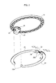
figure 1 shows, in an ideal exploded perspective view, components of embodiments, -
figure 2 shows, once again in an ideal exploded perspective view, parts of components of embodiments, -
figures 3 to 6 , wherefigures 5 and 6 can be grossly assimilated with sectional views along the line V-V infigure 3 shown on an enlarged scale, illustrate operating criteria of embodiments. - In the following description, various specific details aimed at providing a fuller understanding of various embodiments are explained. The embodiments may be implemented without one or more of the specific details or using other methods, components, materials, etc. In other cases, known structures, materials or operations are not shown or described in detail so that the various aspects of the embodiments may be understood more clearly.
- The reference to "an embodiment" in the context of this description indicates that a particular configuration, structure or feature described in relation to the embodiment is included in at least one embodiment. Therefore, phrases such as "in one embodiment", which may occur at various points in this description, do not necessarily refer to the same embodiment. Moreover, particular forms, structures or features may be combined in any suitable manner in one or more embodiments.
- The reference signs used here are provided solely for the sake of convenience and therefore do not define the scope of protection or ambit of the embodiments.
- Various embodiments can relate to a system for mounting recessed lighting sources in an aperture, for example the circular aperture A (see
figure 1 ) provided in a mounting structure such as, for example, a ceiling or a false ceiling S. - In various embodiments, the system can include:
- an
annular fixing member 10 intended to be fitted to the aperture A in the manner of a sealing frame or collar thereof, and - a lighting device 12 (what is termed a luminaire) which can receive a light radiation source L, such as for example an LED "spotlight".
- Even though it is represented for clarity of illustration and is intended to be inserted into a system according to embodiments, the light radiation source L is not in itself an essential component of the embodiments.
- The
lighting device 12 can be of any known type; it may be, for example, an adjustable and/or orientable lighting device as described in a patent application for industrial invention filed on the same date in the name of the same applicants. - In various embodiments, the body of the
lighting device 12 is surrounded by acollar member 14. Thecollar member 14 is intended to support the body of thelighting device 12, being fixed thereto with any known means or, possibly, being realized in one piece therewith. - In various embodiments, the
collar member 14 can be of the type shown infigure 2 , including a circular ring body provided with a ring of lightening and/or ventilation apertures. - In various embodiments, the
collar member 14 can have abody 16 for the mounting of an orientation device of thelighting device 12. - In various embodiments, the
member 14 can be provided, for example in the vicinity of thebody 16, withpins 18 or similar fixing and joint formations for a pair ofjaws 20 having C-shaped, complementary structures, so as to jointly define an (open) annular body which is substantially coextensive with thecollar member 14. - In various embodiments, the two
jaws 20 can have: - a first pair of
homologous ends 20a, positioned adjacent to one another and situated at a fixed distance, intended to be mounted on the pins orsimilar mounting formations 18 provided on thecollar member 14, - a second pair of
homologous ends 20b, adjacent to one another and situated at a variable distance as a result of the oscillation of thejaws 20 around the pins orsimilar mounting formations 18. - In various embodiments, when they are mounted on the collar member 14 (for example owing to the pins or similar mounting formations 18), the two
jaws 20 jointly define a radially contractible and expandable annular body. - In various embodiments, in order to avoid uncontrolled spreading and/or detachment of the
jaws 20 from thecollar member 14 which bears them, the spreading movement of thejaws 20 can be stopped by stop formations (not explicitly visible in the drawings) associated with the pins 18 (or possibly with the body 16). - In various embodiments, a
helical spring 22 can be interposed between theends 20b of the second pair, said helical spring acting as an elastic return member for the jaws in conditions in which theends 20b move apart, thus in a radially expanded state of the annular body jointly defined by thejaws 20. - In various embodiments, at the second
homologous ends 20b (those between which thespring 22 is interposed in the exemplary embodiment considered here), provision can be made of protrudingtongues 26, which can be grasped and moved closer together ("pinched"), so as to move the twojaws 20 closer together and determine radial contraction of the annular body jointly defined thereby. By releasing the tightening or pinching action exerted on thetongues 26, thespring 22 acts so as to spread apart thesecond ends 20b, causing a controlled widening of thejaws 20 according to a mechanism which can be grossly assimilated with the operating movement of the jaws or shoes of a drum brake. - In various embodiments, the inner surface of the
annular fixing member 10 may have, on the wall of its central orifice (seefigure 1 ), aperipheral groove 10a which can constitute an engagement structure for thejaws 20. - The sequence of
figures 3 and 4 schematically shows the operation for inserting thelighting device 12 into thefixing member 10, which is assumed to have been inserted beforehand into the aperture A according to any solution known for this purpose (for example using elasticallyspreadable brackets 10b, currently in use for mounting ceiling spotlights). -
Figures 3 and 4 can therefore be considered to be ideal views from below relating to a situation in which the aperture A (seefigure 1 ) is provided in a ceiling or false ceiling S extending in a horizontal direction. -
Figure 3 (and in coordinationfigure 5 ) show how, by acting on thetongues 26 and tightening them so as to cause them to move together counter to the reaction force exerted by thespring 22, it is possible to determine the radial contraction of the annular body jointly defined by thejaws 20. - In these conditions, the
lighting device 12 can be inserted into the aperture A, the outline of which is "sealed" by theannular fixing member 10. -
Figure 4 (and in coordinationfigure 6 ) show how, by gradually releasing thetongues 26, thespring 22 spreads apart theends 20b of the jaws, which widen so as to engage in thegroove 10a. - In this way, the collar member 14 (and the
lighting device 12 carried thereby) are blocked with respect to theannular fixing member 10, thereby ensuring the fixing of the lighting device 12 (and of the light radiation source L intended to be mounted thereon) in the aperture A in accordance with current mounting methods for recessed lighting sources. - In various embodiments in which the
fixing member 10 and thecollar member 14 are circular, by acting on thetongues 26 it is moreover possible to slightly contract thejaws 22, so as to relax the braking/blocking action exerted thereby with respect to thefixing member 10, in such a manner that, even without arriving at the disconnection of thelighting device 12 from thefixing member 10, thelighting device 12 can be made to rotate so as to vary (about a vertical axis in the case of ceiling mounting) the direction in which the light radiation is projected. - In various embodiments, the ways in which the
lighting device 12 is fixed on thecollar 14 can moreover make it possible to realize an orientation in the sense of varying the "elevation" of the direction in which the light radiation emitted by the source L is projected: this can take place in accordance with known criteria without this affecting the mode of operation of the embodiments, whatever the solution adopted. - It will be understood that various embodiments can provide for the presence of a number of
jaws 20 which differs from two: for example, it is possible to provide for the presence of a single jaw, intended to realize the mounting mechanism described above. - Furthermore, instead of being carried by the collar member 14 (preferably outwardly of the lighting body 12), the jaw or the jaws in question could be carried by the
annular fixing member 10 and be intended to tighten thecollar member 14 with a complementary kinematic arrangement with respect to that illustrated here by way of example. - As a consequence, without affecting the principle of the invention, the constructional details and embodiments may vary, also significantly, with respect to that illustrated here purely by way of non-limiting example, without thereby departing from the scope of protection of the invention. This scope of protection is defined by the accompanying claims.
Claims (10)
- A system for mounting a recessed lighting source in an aperture (A), the system including:- an annular fixing member (10) for fitting to said aperture (A), and- a lighting body (12) surrounded by a collar member (14), said lighting body (12) being insertable into said annular fixing member (10), with one of said annular fixing member (10) and said collar member (14) provided with at least one jaw (20) movable between:- an engaged position, in which the at least one jaw (20) blocks the collar member (14) with respect to the annular fixing member (10) to fix the lighting body (12) to the aperture (A), and- a disengaged position, in which the relative movement of the collar member (14) with respect to the annular fixing member (10) is not impeded by the at least one jaw (20).
- The system as claimed in claim 1, wherein said at least one jaw (20) is elastically urged (22) towards said engaged position.
- The system as claimed in claim 1 or claim 2, wherein said at least one jaw (20) is carried by the collar member (14) of the lighting body (12).
- The system as claimed in any of the preceding claims, including a pair of jaws (20) jointly defining a radially expandable and contractible annular body.
- The system as claimed in claim 4, wherein said jaws (20) have a first pair of homologous ends (20a) at a fixed distance and a second pair of homologous ends (20b) whose distance is variable to radially expand and contract said annular body jointly defined by the jaws (20).
- The system as claimed in claim 5, including a spring (22) interposed between the homologous ends of said second pair of homologous ends (20b) of the jaws (20) to bias said pair of jaws (20) towards a radially expanded or contracted condition of the annular body jointly defined by the jaws (20).
- The system as claimed in claim 5 or claim 6, including a pair of tongue formations (26) protruding from the homologous ends of said second pair of homologous ends (20b) of the jaws (20), whereby pinching of said tongue formations (26) produces radial contraction of the annular body jointly defined by the jaws (20).
- The system as claimed in any of claims 4 to 7, wherein said pair of jaws (20) are mounted on said collar member (14), preferably outwardly of said lighting body (12).
- The system as claimed in any of the preceding claims,
wherein said annular fixing member (10) and said collar member (14) of the lighting body (12) are circular, whereby, with said at least one jaw (20) in said disengaged position, the lighting body (12) is rotatable with respect to the annular fixing member (10). - A lighting device (12) for use in the system as claimed in any of claims 1 to 9, wherein said lighting device (12) carries said collar member (14).
Applications Claiming Priority (1)
| Application Number | Priority Date | Filing Date | Title |
|---|---|---|---|
| ITTO20120767 | 2012-09-05 |
Publications (2)
| Publication Number | Publication Date |
|---|---|
| EP2706284A1 true EP2706284A1 (en) | 2014-03-12 |
| EP2706284B1 EP2706284B1 (en) | 2017-04-05 |
Family
ID=46939881
Family Applications (1)
| Application Number | Title | Priority Date | Filing Date |
|---|---|---|---|
| EP13181904.7A Not-in-force EP2706284B1 (en) | 2012-09-05 | 2013-08-27 | System for mounting lighting devices and corresponding device |
Country Status (1)
| Country | Link |
|---|---|
| EP (1) | EP2706284B1 (en) |
Cited By (3)
| Publication number | Priority date | Publication date | Assignee | Title |
|---|---|---|---|---|
| EP2899458A1 (en) * | 2014-01-22 | 2015-07-29 | Tons Lightology Inc. | LED light fixture |
| WO2020057658A1 (en) * | 2018-09-21 | 2020-03-26 | 欧普照明股份有限公司 | Spotlight support, and spotlight |
| US20220205617A1 (en) * | 2019-05-13 | 2022-06-30 | Halodawn Ltd | A collar for a recessed light fitting |
Citations (3)
| Publication number | Priority date | Publication date | Assignee | Title |
|---|---|---|---|---|
| DE9317677U1 (en) * | 1993-11-19 | 1994-02-24 | Trimborn, Gerd, 58706 Menden | Device for holding electrical halogen cold light mirrors on ceiling installation or construction elements |
| WO2008051957A2 (en) * | 2006-10-23 | 2008-05-02 | Cree Led Lighting Solutions, Inc. | Lighting devices and methods of installing light engine housings and/or trim elements in lighting device housings |
| GB2450986A (en) * | 2007-07-09 | 2009-01-14 | Microlights Ltd | Recessed downlighter |
-
2013
- 2013-08-27 EP EP13181904.7A patent/EP2706284B1/en not_active Not-in-force
Patent Citations (3)
| Publication number | Priority date | Publication date | Assignee | Title |
|---|---|---|---|---|
| DE9317677U1 (en) * | 1993-11-19 | 1994-02-24 | Trimborn, Gerd, 58706 Menden | Device for holding electrical halogen cold light mirrors on ceiling installation or construction elements |
| WO2008051957A2 (en) * | 2006-10-23 | 2008-05-02 | Cree Led Lighting Solutions, Inc. | Lighting devices and methods of installing light engine housings and/or trim elements in lighting device housings |
| GB2450986A (en) * | 2007-07-09 | 2009-01-14 | Microlights Ltd | Recessed downlighter |
Cited By (5)
| Publication number | Priority date | Publication date | Assignee | Title |
|---|---|---|---|---|
| EP2899458A1 (en) * | 2014-01-22 | 2015-07-29 | Tons Lightology Inc. | LED light fixture |
| WO2020057658A1 (en) * | 2018-09-21 | 2020-03-26 | 欧普照明股份有限公司 | Spotlight support, and spotlight |
| US11378265B2 (en) | 2018-09-21 | 2022-07-05 | Opple Lighting Co., Ltd. | Spot lamp holder and spot lamp |
| US20220205617A1 (en) * | 2019-05-13 | 2022-06-30 | Halodawn Ltd | A collar for a recessed light fitting |
| US11598510B2 (en) * | 2019-05-13 | 2023-03-07 | Halodawn Ltd | Collar for a recessed light fitting |
Also Published As
| Publication number | Publication date |
|---|---|
| EP2706284B1 (en) | 2017-04-05 |
Similar Documents
| Publication | Publication Date | Title |
|---|---|---|
| EP2706284B1 (en) | System for mounting lighting devices and corresponding device | |
| MX2019001415A (en) | Luminaire. | |
| EP4349652A4 (en) | Projection device for vehicle, method of operating same, and light fixture for vehicle | |
| KR20190067434A (en) | Embeded type led lighting device | |
| CN204141416U (en) | A kind of recessed light fixture | |
| EP3153767A1 (en) | A lighting device and corresponding method | |
| US20170009964A1 (en) | Engagement system and method for mounting lighting fixture | |
| WO2012091660A1 (en) | Attachment means, light fittings, use of a roller-type spring and a method for mounting of light fittings | |
| US20170009963A1 (en) | Engagement mechanism and method for mounting lighting fixture | |
| MX350552B (en) | Ceiling clamp for recessed light mounting. | |
| US20150219325A1 (en) | Twist lock optical holder for recessed lighting | |
| US10168034B2 (en) | Downlight | |
| EP3966499A4 (en) | Frame system for a lighting fixture | |
| KR101557054B1 (en) | Down light device | |
| US8794784B1 (en) | Recessed can lampshade accessory | |
| CN103672795A (en) | Adjustable support for lighting sources | |
| EP4462016A1 (en) | Led lighting device | |
| EP4446649A1 (en) | Led lighting device | |
| EP3193079B1 (en) | A mounting device for lighting sources and corresponding method | |
| AU2014277663A1 (en) | A tool for removing an optic assembly used in a downlight | |
| EP4308852A4 (en) | Ceiling fixture accessibility device | |
| EM87632470001S (en) | Floodlight projectors | |
| EM87224170008S (en) | Floodlight projectors | |
| EM87224170002S (en) | Floodlight projectors | |
| EM87224170003S (en) | Floodlight projectors |
Legal Events
| Date | Code | Title | Description |
|---|---|---|---|
| PUAI | Public reference made under article 153(3) epc to a published international application that has entered the european phase |
Free format text: ORIGINAL CODE: 0009012 |
|
| AK | Designated contracting states |
Kind code of ref document: A1 Designated state(s): AL AT BE BG CH CY CZ DE DK EE ES FI FR GB GR HR HU IE IS IT LI LT LU LV MC MK MT NL NO PL PT RO RS SE SI SK SM TR |
|
| AX | Request for extension of the european patent |
Extension state: BA ME |
|
| 17P | Request for examination filed |
Effective date: 20140912 |
|
| RBV | Designated contracting states (corrected) |
Designated state(s): AL AT BE BG CH CY CZ DE DK EE ES FI FR GB GR HR HU IE IS IT LI LT LU LV MC MK MT NL NO PL PT RO RS SE SI SK SM TR |
|
| RIC1 | Information provided on ipc code assigned before grant |
Ipc: F21S 8/02 20060101AFI20161026BHEP Ipc: F21V 17/16 20060101ALI20161026BHEP |
|
| GRAP | Despatch of communication of intention to grant a patent |
Free format text: ORIGINAL CODE: EPIDOSNIGR1 |
|
| INTG | Intention to grant announced |
Effective date: 20161207 |
|
| GRAS | Grant fee paid |
Free format text: ORIGINAL CODE: EPIDOSNIGR3 |
|
| GRAA | (expected) grant |
Free format text: ORIGINAL CODE: 0009210 |
|
| AK | Designated contracting states |
Kind code of ref document: B1 Designated state(s): AL AT BE BG CH CY CZ DE DK EE ES FI FR GB GR HR HU IE IS IT LI LT LU LV MC MK MT NL NO PL PT RO RS SE SI SK SM TR |
|
| REG | Reference to a national code |
Ref country code: GB Ref legal event code: FG4D |
|
| REG | Reference to a national code |
Ref country code: CH Ref legal event code: EP |
|
| REG | Reference to a national code |
Ref country code: AT Ref legal event code: REF Ref document number: 882161 Country of ref document: AT Kind code of ref document: T Effective date: 20170415 |
|
| REG | Reference to a national code |
Ref country code: IE Ref legal event code: FG4D |
|
| REG | Reference to a national code |
Ref country code: DE Ref legal event code: R096 Ref document number: 602013019367 Country of ref document: DE |
|
| REG | Reference to a national code |
Ref country code: NL Ref legal event code: MP Effective date: 20170405 |
|
| REG | Reference to a national code |
Ref country code: LT Ref legal event code: MG4D |
|
| REG | Reference to a national code |
Ref country code: AT Ref legal event code: MK05 Ref document number: 882161 Country of ref document: AT Kind code of ref document: T Effective date: 20170405 |
|
| PG25 | Lapsed in a contracting state [announced via postgrant information from national office to epo] |
Ref country code: NL Free format text: LAPSE BECAUSE OF FAILURE TO SUBMIT A TRANSLATION OF THE DESCRIPTION OR TO PAY THE FEE WITHIN THE PRESCRIBED TIME-LIMIT Effective date: 20170405 |
|
| PG25 | Lapsed in a contracting state [announced via postgrant information from national office to epo] |
Ref country code: AT Free format text: LAPSE BECAUSE OF FAILURE TO SUBMIT A TRANSLATION OF THE DESCRIPTION OR TO PAY THE FEE WITHIN THE PRESCRIBED TIME-LIMIT Effective date: 20170405 Ref country code: FI Free format text: LAPSE BECAUSE OF FAILURE TO SUBMIT A TRANSLATION OF THE DESCRIPTION OR TO PAY THE FEE WITHIN THE PRESCRIBED TIME-LIMIT Effective date: 20170405 Ref country code: ES Free format text: LAPSE BECAUSE OF FAILURE TO SUBMIT A TRANSLATION OF THE DESCRIPTION OR TO PAY THE FEE WITHIN THE PRESCRIBED TIME-LIMIT Effective date: 20170405 Ref country code: NO Free format text: LAPSE BECAUSE OF FAILURE TO SUBMIT A TRANSLATION OF THE DESCRIPTION OR TO PAY THE FEE WITHIN THE PRESCRIBED TIME-LIMIT Effective date: 20170705 Ref country code: GR Free format text: LAPSE BECAUSE OF FAILURE TO SUBMIT A TRANSLATION OF THE DESCRIPTION OR TO PAY THE FEE WITHIN THE PRESCRIBED TIME-LIMIT Effective date: 20170706 Ref country code: HR Free format text: LAPSE BECAUSE OF FAILURE TO SUBMIT A TRANSLATION OF THE DESCRIPTION OR TO PAY THE FEE WITHIN THE PRESCRIBED TIME-LIMIT Effective date: 20170405 Ref country code: LT Free format text: LAPSE BECAUSE OF FAILURE TO SUBMIT A TRANSLATION OF THE DESCRIPTION OR TO PAY THE FEE WITHIN THE PRESCRIBED TIME-LIMIT Effective date: 20170405 |
|
| PGFP | Annual fee paid to national office [announced via postgrant information from national office to epo] |
Ref country code: DE Payment date: 20170822 Year of fee payment: 5 |
|
| PG25 | Lapsed in a contracting state [announced via postgrant information from national office to epo] |
Ref country code: BG Free format text: LAPSE BECAUSE OF FAILURE TO SUBMIT A TRANSLATION OF THE DESCRIPTION OR TO PAY THE FEE WITHIN THE PRESCRIBED TIME-LIMIT Effective date: 20170705 Ref country code: IS Free format text: LAPSE BECAUSE OF FAILURE TO SUBMIT A TRANSLATION OF THE DESCRIPTION OR TO PAY THE FEE WITHIN THE PRESCRIBED TIME-LIMIT Effective date: 20170805 Ref country code: SE Free format text: LAPSE BECAUSE OF FAILURE TO SUBMIT A TRANSLATION OF THE DESCRIPTION OR TO PAY THE FEE WITHIN THE PRESCRIBED TIME-LIMIT Effective date: 20170405 Ref country code: LV Free format text: LAPSE BECAUSE OF FAILURE TO SUBMIT A TRANSLATION OF THE DESCRIPTION OR TO PAY THE FEE WITHIN THE PRESCRIBED TIME-LIMIT Effective date: 20170405 Ref country code: RS Free format text: LAPSE BECAUSE OF FAILURE TO SUBMIT A TRANSLATION OF THE DESCRIPTION OR TO PAY THE FEE WITHIN THE PRESCRIBED TIME-LIMIT Effective date: 20170405 Ref country code: PL Free format text: LAPSE BECAUSE OF FAILURE TO SUBMIT A TRANSLATION OF THE DESCRIPTION OR TO PAY THE FEE WITHIN THE PRESCRIBED TIME-LIMIT Effective date: 20170405 |
|
| REG | Reference to a national code |
Ref country code: DE Ref legal event code: R097 Ref document number: 602013019367 Country of ref document: DE |
|
| PG25 | Lapsed in a contracting state [announced via postgrant information from national office to epo] |
Ref country code: RO Free format text: LAPSE BECAUSE OF FAILURE TO SUBMIT A TRANSLATION OF THE DESCRIPTION OR TO PAY THE FEE WITHIN THE PRESCRIBED TIME-LIMIT Effective date: 20170405 Ref country code: DK Free format text: LAPSE BECAUSE OF FAILURE TO SUBMIT A TRANSLATION OF THE DESCRIPTION OR TO PAY THE FEE WITHIN THE PRESCRIBED TIME-LIMIT Effective date: 20170405 Ref country code: EE Free format text: LAPSE BECAUSE OF FAILURE TO SUBMIT A TRANSLATION OF THE DESCRIPTION OR TO PAY THE FEE WITHIN THE PRESCRIBED TIME-LIMIT Effective date: 20170405 Ref country code: SK Free format text: LAPSE BECAUSE OF FAILURE TO SUBMIT A TRANSLATION OF THE DESCRIPTION OR TO PAY THE FEE WITHIN THE PRESCRIBED TIME-LIMIT Effective date: 20170405 Ref country code: CZ Free format text: LAPSE BECAUSE OF FAILURE TO SUBMIT A TRANSLATION OF THE DESCRIPTION OR TO PAY THE FEE WITHIN THE PRESCRIBED TIME-LIMIT Effective date: 20170405 |
|
| PLBE | No opposition filed within time limit |
Free format text: ORIGINAL CODE: 0009261 |
|
| STAA | Information on the status of an ep patent application or granted ep patent |
Free format text: STATUS: NO OPPOSITION FILED WITHIN TIME LIMIT |
|
| PG25 | Lapsed in a contracting state [announced via postgrant information from national office to epo] |
Ref country code: IT Free format text: LAPSE BECAUSE OF FAILURE TO SUBMIT A TRANSLATION OF THE DESCRIPTION OR TO PAY THE FEE WITHIN THE PRESCRIBED TIME-LIMIT Effective date: 20170405 Ref country code: SM Free format text: LAPSE BECAUSE OF FAILURE TO SUBMIT A TRANSLATION OF THE DESCRIPTION OR TO PAY THE FEE WITHIN THE PRESCRIBED TIME-LIMIT Effective date: 20170405 |
|
| 26N | No opposition filed |
Effective date: 20180108 |
|
| REG | Reference to a national code |
Ref country code: CH Ref legal event code: PL |
|
| PG25 | Lapsed in a contracting state [announced via postgrant information from national office to epo] |
Ref country code: MC Free format text: LAPSE BECAUSE OF FAILURE TO SUBMIT A TRANSLATION OF THE DESCRIPTION OR TO PAY THE FEE WITHIN THE PRESCRIBED TIME-LIMIT Effective date: 20170405 |
|
| GBPC | Gb: european patent ceased through non-payment of renewal fee |
Effective date: 20170827 |
|
| PG25 | Lapsed in a contracting state [announced via postgrant information from national office to epo] |
Ref country code: CH Free format text: LAPSE BECAUSE OF NON-PAYMENT OF DUE FEES Effective date: 20170831 Ref country code: LI Free format text: LAPSE BECAUSE OF NON-PAYMENT OF DUE FEES Effective date: 20170831 |
|
| REG | Reference to a national code |
Ref country code: FR Ref legal event code: ST Effective date: 20180430 |
|
| REG | Reference to a national code |
Ref country code: IE Ref legal event code: MM4A |
|
| PG25 | Lapsed in a contracting state [announced via postgrant information from national office to epo] |
Ref country code: SI Free format text: LAPSE BECAUSE OF FAILURE TO SUBMIT A TRANSLATION OF THE DESCRIPTION OR TO PAY THE FEE WITHIN THE PRESCRIBED TIME-LIMIT Effective date: 20170405 |
|
| REG | Reference to a national code |
Ref country code: BE Ref legal event code: MM Effective date: 20170831 |
|
| PG25 | Lapsed in a contracting state [announced via postgrant information from national office to epo] |
Ref country code: LU Free format text: LAPSE BECAUSE OF NON-PAYMENT OF DUE FEES Effective date: 20170827 |
|
| PG25 | Lapsed in a contracting state [announced via postgrant information from national office to epo] |
Ref country code: GB Free format text: LAPSE BECAUSE OF NON-PAYMENT OF DUE FEES Effective date: 20170827 Ref country code: IE Free format text: LAPSE BECAUSE OF NON-PAYMENT OF DUE FEES Effective date: 20170827 |
|
| PG25 | Lapsed in a contracting state [announced via postgrant information from national office to epo] |
Ref country code: FR Free format text: LAPSE BECAUSE OF NON-PAYMENT OF DUE FEES Effective date: 20170831 Ref country code: BE Free format text: LAPSE BECAUSE OF NON-PAYMENT OF DUE FEES Effective date: 20170831 |
|
| PG25 | Lapsed in a contracting state [announced via postgrant information from national office to epo] |
Ref country code: MT Free format text: LAPSE BECAUSE OF NON-PAYMENT OF DUE FEES Effective date: 20170827 |
|
| REG | Reference to a national code |
Ref country code: DE Ref legal event code: R119 Ref document number: 602013019367 Country of ref document: DE |
|
| PG25 | Lapsed in a contracting state [announced via postgrant information from national office to epo] |
Ref country code: HU Free format text: LAPSE BECAUSE OF FAILURE TO SUBMIT A TRANSLATION OF THE DESCRIPTION OR TO PAY THE FEE WITHIN THE PRESCRIBED TIME-LIMIT; INVALID AB INITIO Effective date: 20130827 |
|
| PG25 | Lapsed in a contracting state [announced via postgrant information from national office to epo] |
Ref country code: DE Free format text: LAPSE BECAUSE OF NON-PAYMENT OF DUE FEES Effective date: 20190301 |
|
| PG25 | Lapsed in a contracting state [announced via postgrant information from national office to epo] |
Ref country code: CY Free format text: LAPSE BECAUSE OF NON-PAYMENT OF DUE FEES Effective date: 20170405 |
|
| PG25 | Lapsed in a contracting state [announced via postgrant information from national office to epo] |
Ref country code: MK Free format text: LAPSE BECAUSE OF FAILURE TO SUBMIT A TRANSLATION OF THE DESCRIPTION OR TO PAY THE FEE WITHIN THE PRESCRIBED TIME-LIMIT Effective date: 20170405 |
|
| PG25 | Lapsed in a contracting state [announced via postgrant information from national office to epo] |
Ref country code: TR Free format text: LAPSE BECAUSE OF FAILURE TO SUBMIT A TRANSLATION OF THE DESCRIPTION OR TO PAY THE FEE WITHIN THE PRESCRIBED TIME-LIMIT Effective date: 20170405 |
|
| PG25 | Lapsed in a contracting state [announced via postgrant information from national office to epo] |
Ref country code: PT Free format text: LAPSE BECAUSE OF FAILURE TO SUBMIT A TRANSLATION OF THE DESCRIPTION OR TO PAY THE FEE WITHIN THE PRESCRIBED TIME-LIMIT Effective date: 20170405 |
|
| PG25 | Lapsed in a contracting state [announced via postgrant information from national office to epo] |
Ref country code: AL Free format text: LAPSE BECAUSE OF FAILURE TO SUBMIT A TRANSLATION OF THE DESCRIPTION OR TO PAY THE FEE WITHIN THE PRESCRIBED TIME-LIMIT Effective date: 20170405 |