EP2706266A1 - Planetary friction gear continuously variable transmission - Google Patents
Planetary friction gear continuously variable transmission Download PDFInfo
- Publication number
- EP2706266A1 EP2706266A1 EP12782889.5A EP12782889A EP2706266A1 EP 2706266 A1 EP2706266 A1 EP 2706266A1 EP 12782889 A EP12782889 A EP 12782889A EP 2706266 A1 EP2706266 A1 EP 2706266A1
- Authority
- EP
- European Patent Office
- Prior art keywords
- friction gear
- planetary friction
- input
- roller
- output
- Prior art date
- Legal status (The legal status is an assumption and is not a legal conclusion. Google has not performed a legal analysis and makes no representation as to the accuracy of the status listed.)
- Granted
Links
- 230000005540 biological transmission Effects 0.000 title claims abstract description 45
- 238000005096 rolling process Methods 0.000 claims abstract description 8
- 238000003825 pressing Methods 0.000 claims description 10
- 230000000694 effects Effects 0.000 description 5
- 230000007246 mechanism Effects 0.000 description 5
- ATJFFYVFTNAWJD-UHFFFAOYSA-N Tin Chemical compound [Sn] ATJFFYVFTNAWJD-UHFFFAOYSA-N 0.000 description 1
- 238000000034 method Methods 0.000 description 1
- 230000004048 modification Effects 0.000 description 1
- 238000012986 modification Methods 0.000 description 1
- 238000009987 spinning Methods 0.000 description 1
Images



Classifications
-
- F—MECHANICAL ENGINEERING; LIGHTING; HEATING; WEAPONS; BLASTING
- F16—ENGINEERING ELEMENTS AND UNITS; GENERAL MEASURES FOR PRODUCING AND MAINTAINING EFFECTIVE FUNCTIONING OF MACHINES OR INSTALLATIONS; THERMAL INSULATION IN GENERAL
- F16H—GEARING
- F16H15/00—Gearings for conveying rotary motion with variable gear ratio, or for reversing rotary motion, by friction between rotary members
- F16H15/48—Gearings for conveying rotary motion with variable gear ratio, or for reversing rotary motion, by friction between rotary members with members having orbital motion
- F16H15/50—Gearings providing a continuous range of gear ratios
-
- F—MECHANICAL ENGINEERING; LIGHTING; HEATING; WEAPONS; BLASTING
- F16—ENGINEERING ELEMENTS AND UNITS; GENERAL MEASURES FOR PRODUCING AND MAINTAINING EFFECTIVE FUNCTIONING OF MACHINES OR INSTALLATIONS; THERMAL INSULATION IN GENERAL
- F16H—GEARING
- F16H15/00—Gearings for conveying rotary motion with variable gear ratio, or for reversing rotary motion, by friction between rotary members
- F16H15/48—Gearings for conveying rotary motion with variable gear ratio, or for reversing rotary motion, by friction between rotary members with members having orbital motion
- F16H15/50—Gearings providing a continuous range of gear ratios
- F16H15/52—Gearings providing a continuous range of gear ratios in which a member of uniform effective diameter mounted on a shaft may co-operate with different parts of another member
Definitions
- the present invention relates to a planetary friction gear continuously variable transmission.
- a planetary friction gear continuously variable transmission using a cone-like-shaped (tapered) planetary gear mechanism as a continuously variable transmission is known.
- a planetary friction gear continuously variable transmission is disclosed in Patent Document 1 in which: a torque from an input shaft is transmitted to an output shaft via a carrier, a tapered roller, and a ring roller; and a forward rotation, a counter rotation, or no rotation of the output shaft relative to the input shaft is carried out by varying the contact position of a transmission ring and the tapered roller.
- Patent Document 1 Japanese Patent Application Publication No. 2011-56985
- a loading mechanism in which a rolling body is installed in the circular groove between the ring roller and the output shaft is provided for loading torque.
- the loading mechanism is configured as that when a torque differential arises between the ring roller and the output shaft, the rolling body presses the ring roller and the output shaft in the axial direction to carry out torque loading.
- the present invention is directed to such issue described above.
- the object of the present invention is to improve the efficiency of torque loading of the planetary friction gear continuously variable transmission by producing a sufficient degree of pressing force at the contact point between the tapered roller and the transmission ring.
- a planetary friction gear continuously variable transmission of the present invention includes: an input shaft which is rotatably supported in a case; a carrier formed in a hollow cone-like-shape with a trapezoid cross section in which an outer diameter in an output side is smaller than an outer diameter in an input side, an opening is formed in an outer periphery of the cone, and an output-side end portion of the input shaft is fixed to an outer side surface of a bottom section; a planetary friction gear which is rotatably arranged in an opening of the carrier including, in an order from an input side, a first tapered roller, a second tapered roller, and a third tapered roller on a rotating shaft inclined against an axis of the input shaft; an input-side support section formed by notching a portion of an outer periphery of a bottom section of the carrier, which rotatably supports an input-side end portion of an rotating shaft of the planetary friction gear; a sun roller, provided on a same line
- the input-side support section may be formed by notching a portion of an outer periphery of the carrier bottom section in a V-shaped groove.
- An input-side end portion of a rotating shaft of the planetary friction gear may be rotatably supported by the input-side support section via a bearing.
- the planetary friction gear continuously variable transmission may further includes an output-side support section which is formed by notching an outer periphery of the carrier top section and rotatably supports an output-side end portion of a rotating axis of the planetary friction gear.
- the output-side support section is formed by notching a portion of an outer periphery of the carrier top section in a form of V-shaped groove.
- An output-side end portion of a rotating shaft of the planetary friction gear may be rotatably supported by the output-side support section via a bearing.
- the torque loading efficiency can effectively be improved by producing a sufficient degree of pressing force at a contact point between the tapered roller and the transmission ring.
- a planetary friction gear continuously variable transmission according to one embodiment of the present invention will be described based on Figs. 1 to 7 .
- the same numeral is used for identical elements and names and functions thereof are also the same. Therefore a detailed description on such element will not be repeated.
- a planetary friction gear continuously variable transmission 10 of the embodiment includes a main case 11, an input shaft 12, a carrier 13, a planetary friction gear 16, a sun roller 17, a ring roller 19, an output shaft 20, a transmission ring 21, and a loading cam section 22.
- illustration of the configuration of the lower half of the planetary friction gear continuously variable transmission 10 is omitted for the convenience of description.
- the main case 11 contains therein each of the mechanisms of the planetary friction gear continuously variable transmission 10.
- a bearing 30 and 31 is provided at one of both sides of the main case 11 respectively to rotatably support the input shaft 12, and a bearing 31 is provided at another side of the main case 11 to rotatably support the output shaft 20.
- the input shaft 12 is connected to a rotating shaft of an engine, which is not shown in the drawing, via a clutch or the like. Further, the input side of the input shaft 12 is inserted into the bearing 30 of the main case 11, and the output side of the input shaft 12 is connected to the carrier 13.
- the carrier 13 is formed in a cone-like-shape with a trapezoid cross section in which an outer diameter in the output side is smaller than an outer diameter in the input side.
- a hollow portion in which the sun roller 16, which will be described later, is rotatably contained is formed inside the carrier 13.
- the output-side end portion of the input shaft 12 is fixed to the outer side surface of the carrier bottom section 13a, and an opening 13b, in which a planetary friction gear 16 is contained which will be described later, is formed in the conical outer periphery of the carrier 13.
- the number of openings 13b is determined corresponding to the number (e.g., three to five) of the planetary friction gear 16.
- an input-side tapered roller support section 14 is provided in the outer periphery of the carrier bottom surface 13a
- an output-side tapered roller support section 15 is provided in the outer periphery of the carrier top section 13c.
- the number of the input-side tapered roller support section 14 and the output-side tapered roller support section 15 is determined corresponding to the number (e.g., three to five) of the planetary friction gear 16.
- the input-side tapered roller support section 14 is formed by notching a portion of the outer periphery of the carrier bottom section 13a in a V-shape. That is, the input-side tapered roller support section 14 is configured with a V-shaped groove 14a formed by notching the carrier bottom section 13a in a V-shape from the outer periphery toward the axial center. In the V-shaped groove 14a, the input-side end portion of a rotating shaft 16d of the planetary friction gear 16 is rotatably supported via a bearing 14b.
- the output-side tapered roller support section 15 is formed by notching a portion of the outer periphery of the carrier top section 13c in a V-shape. That is, the output-side tapered roller support section 15 is configured with a V-shaped groove 15a formed by notching the carrier top section 13c in a V-shape from the outer periphery toward the axial center. In the V-shaped groove 15a, the output-side end portion of the rotating shaft 16d of the planetary friction gear 16 is rotatably supported via a bearing 15b.
- a plurality (e.g., three to five) of the planetary friction gears 16 is provided and arranged so as the rotating shaft 16d inclines in a manner that the distance between the rotating shaft 16d and the axis of the sun roller 17 in the output side is smaller than that in the input side.
- the sun roller 17 is provided so that the axis thereof is provided on the same line as the input shaft 12.
- the planetary friction gear 16 includes, in an order from the input side, a first tapered roller 16a, a second tapered roller 16b, and a third tapered roller 16c.
- the first tapered roller 16a, the second tapered roller 16b, and the third tapered roller 16c are provided so as to integrally rotate with the rotating shaft 16d.
- the first tapered roller 16a and the third tapered roller 16c are formed in a cone-like-shape (tapered-shape) in which an outer diameter in the output side is smaller than an outer diameter in the input side. It is configured that the first tapered roller 16a contacts a first roller 17a of the sun roller 17 and the third tapered roller 16c contacts a second roller 17b of the sun roller 17, thereby, rotating the sun roller 17 about a rotating shaft 17c.
- the second tapered roller 16b is formed in a cone-like-shape (tapered-shape) in which an outer diameter in the output side is greater than an outer diameter in the input side, and so as the outer periphery surface of the second tapered roller 16b at the far side from the input shaft 12 or the rotating shaft 17c to be parallel to the axes of the input shaft 12 and the rotating shaft 17c. Further, it is configured that the second tapered roller 16b is in contact with the inner surface of the transmission ring 21, thereby spinning along with the rotation of the carrier 13.
- the sun roller 17 is rotatably arranged inside the hollow portion of the carrier 13 so that the rotating shaft 17c of the sun roller 17 is positioned on the same line as the axis of the input shaft 12. Further, a first roller 17a which contacts the first tapered roller 16a is provided at the input-side end portion of the rotating shaft 17c, and a second roller 17b which contacts the third tapered roller 16c is provided at the output-side end portion of the rotating shaft 17c.
- the first roller 17a and the second roller 17b are formed in a cone-like-shape (tapered-shape) in which an outer diameter in the output side is smaller than an outer diameter in the input side.
- the ring roller 19 is formed in a cylindrical shape with a bottom, and arranged in a manner that the opening facing the input side and the axis of the ring roller 19 is provided on the same line as the output shaft 20.
- An inclined surface 19a having an inclination so that the diameter at the output side is smaller than that at the input side, is formed at the opening of the ring roller 19.
- the inclined surface 19a is configured to contact the third tapered roller 16c, by which the inclined surface 19a rotates.
- the output shaft 20 is rotatably supported in the main case 11 via the bearing 31 in a manner that the axis of the output shaft 20 is positioned on the same line as the input shaft 12. Further, the input-side end portion of the output shaft 20 is connected to the ring roller 19 via the loading cam section 22.
- the transmission ring 21 is screwed to a screw shaft 21a which is provided in the main case 11 so as to be parallel to the input shaft 12.
- a stepping motor for rotating the screw shaft 21a which is not shown in the drawing, is provided at an end portion of the screw shaft 21a. It is configured that the screw shaft 21a rotates according to a command of shifting speed, thereby moving the transmission ring 21 in the axial direction of the input shaft 12 (X-Y direction in Fig. 1 ).
- the loading cam section 22 is configured to have a circular groove 22a formed between the ring roller 19 and the output shaft 20 in which a tapered shape is formed in the direction of rotation, and a ball (rolling body) 22b provided inside the circular groove 22a as illustrated in Fig. 4 .
- the loading cam section 22 is configured so that the ball 22b presses the ring roller 19 and the output shaft 20 in the axial direction when the state changes from no load condition (see Fig. 5(a) ) to loading condition (see Fig. 5(b) ) in which a torque differential arises, whereby the torque loading is carrying out.
- the circular groove 22a may be in any form if a tapered shape can be formed therein in the direction of rotation, and may be, for example, a V-shaped groove.
- the sun roller 17 since the first roller 17a is in contact with the first tapered roller 16a of the planetary friction gear 16 and the second roller 17b is in contact with the third tapered roller 16c of the planetary friction gear 16, the sun roller 17 rotates in the direction opposite to the spin direction of these tapered rollers 16a to 16c.
- the ring roller 19 Since the ring roller 19 is in contact with the third tapered roller 16c of the planetary friction gear 16, the ring roller 19 rotates in the direction opposite to the spin direction of the third tapered roller 16c, by which the torque differential arises between the ring roller 19 and the output shaft 20. And by the torque differential, the ring roller 19 and the output shaft 20 are pressed in the axial direction by the ball 22b of the loading cam section 22, and thereby the output shaft 20 rotates together with the ring roller 19.
- the input-side end portion is supported by the V-shaped groove 14a
- the output-side end portion is supported by the V-shaped groove 15a. That is, when the planetary friction gear continuously variable transmission 10 is in a stop, the input-side end portion of the rotating shaft 16d sits in the bottom of the V-shaped groove 14a, and on the other hand, the output-side end portion of the rotating shaft 16d sits in the bottom of the V-shaped groove 15a.
- the planetary friction gear 16 can be positioned in the center of the input-side tapered roller support section 14 and the output-side tapered roller support section 15.
- the input-side tapered roller support section 14 is not necessarily be formed in a groove having a V-shape, and may be formed by linearly notching a portion of the outer periphery of the carrier 13 as described in Fig. 8(a) .
- the output-side tapered roller support section 15 may be formed by linearly notching a portion of the outer periphery of the carrier top section 13c as described in Fig. 8(b) .
- the rotating shaft 16d is pushed outward from the center of the revolution, thereby increasing the revolution radius of the planetary friction gear 16, and whereby an effect similar to that of the embodiment described above can be obtained.
Landscapes
- Engineering & Computer Science (AREA)
- General Engineering & Computer Science (AREA)
- Mechanical Engineering (AREA)
- Friction Gearing (AREA)
Abstract
Description
- The present invention relates to a planetary friction gear continuously variable transmission.
- A planetary friction gear continuously variable transmission using a cone-like-shaped (tapered) planetary gear mechanism as a continuously variable transmission is known. For example, a planetary friction gear continuously variable transmission is disclosed in Patent Document 1 in which: a torque from an input shaft is transmitted to an output shaft via a carrier, a tapered roller, and a ring roller; and a forward rotation, a counter rotation, or no rotation of the output shaft relative to the input shaft is carried out by varying the contact position of a transmission ring and the tapered roller.
- Patent Document 1: Japanese Patent Application Publication No.
2011-56985 - In the planetary friction gear continuously variable transmission described above, a loading mechanism in which a rolling body is installed in the circular groove between the ring roller and the output shaft is provided for loading torque. The loading mechanism is configured as that when a torque differential arises between the ring roller and the output shaft, the rolling body presses the ring roller and the output shaft in the axial direction to carry out torque loading.
- However, in the technique described above, sufficient pressing force at a contact point between the tapered roller and the transmission ring may not be obtained since the movement of the tapered roller in the axial direction is obstructed by an effect caused by a friction force or accuracy at each contact portion between the tapered roller, the ring roller, or the like.
- The present invention is directed to such issue described above. The object of the present invention is to improve the efficiency of torque loading of the planetary friction gear continuously variable transmission by producing a sufficient degree of pressing force at the contact point between the tapered roller and the transmission ring.
- In order to solve the above-described object, a planetary friction gear continuously variable transmission of the present invention includes: an input shaft which is rotatably supported in a case; a carrier formed in a hollow cone-like-shape with a trapezoid cross section in which an outer diameter in an output side is smaller than an outer diameter in an input side, an opening is formed in an outer periphery of the cone, and an output-side end portion of the input shaft is fixed to an outer side surface of a bottom section; a planetary friction gear which is rotatably arranged in an opening of the carrier including, in an order from an input side, a first tapered roller, a second tapered roller, and a third tapered roller on a rotating shaft inclined against an axis of the input shaft; an input-side support section formed by notching a portion of an outer periphery of a bottom section of the carrier, which rotatably supports an input-side end portion of an rotating shaft of the planetary friction gear; a sun roller, provided on a same line as the input shaft, which is in contact with the first tapered roller and the third tapered roller, and thereby rotates; a ring roller, provided on a same line as the input shaft, of which inner circumferential surface is in contact with the third tapered roller, and thereby rotates; an output shaft, provided spaced from an output-side end portion of the ring roller on a same line as the input shaft, which is rotatably supported in the case; a loading section including a rolling body, the rolling body pressing the ring roller and the output shaft in an axial direction when a torque differential arises between the ring roller and the output shaft and being provided in a tapered-shape groove formed between the ring roller and the output shaft; and a transmission ring, provided movable in an axial direction of the input shaft, of which inner circumferential surface is in contact with at least a portion of an outer periphery surface of the second tapered roller, thereby allowing the planetary friction gear to spin.
- The input-side support section may be formed by notching a portion of an outer periphery of the carrier bottom section in a V-shaped groove.
- An input-side end portion of a rotating shaft of the planetary friction gear may be rotatably supported by the input-side support section via a bearing.
- The planetary friction gear continuously variable transmission may further includes an output-side support section which is formed by notching an outer periphery of the carrier top section and rotatably supports an output-side end portion of a rotating axis of the planetary friction gear.
- The output-side support section is formed by notching a portion of an outer periphery of the carrier top section in a form of V-shaped groove.
- An output-side end portion of a rotating shaft of the planetary friction gear may be rotatably supported by the output-side support section via a bearing.
- According to a planetary friction gear continuously variable transmission of the present invention, the torque loading efficiency can effectively be improved by producing a sufficient degree of pressing force at a contact point between the tapered roller and the transmission ring.
-
-
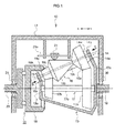
Fig.1 is a schematic local cross sectional view illustrating a planetary friction gear continuously variable transmission according to one embodiment of the present invention. -
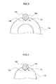
Fig. 2 is a view from arrow A inFig. 1 . -
Fig. 3 is a view from arrow B inFig. 1 . -
Fig. 4 is a schematic side view illustrating a loading cam section of a planetary friction gear continuously variable transmission according to one embodiment of the present invention. -
Fig. 5(a) is a sectional view taken along section A-A ofFig. 4 illustrating a state of a loading cam section under a no load condition. -
Fig. 5(b) is a sectional view taken along section A-A ofFig. 4 illustrating a state of a loading cam section under a loading condition. -
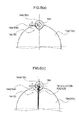
Fig. 6(a) is a schematic front view illustrating a pressing force acting on a rotating shaft of a planetary friction gear. -
Fig. 6(b) is a schematic front view illustrating a state in which a revolution radius of a rotating shaft of a planetary friction gear is increased. -
Fig. 7 is a schematic front view illustrating a contact surface pressing force acting between a planetary friction gear and a transmission ring. -
Fig. 8(a) is a schematic front view illustrating a portion of an input-side tapered roller support section according to another embodiment. -
Fig. 8(b) is a schematic front view illustrating a portion of an output-side tapered roller support section according to another embodiment. -
Fig. 9 is a schematic front view illustrating a state in which a revolution radius of a rotating shaft of a planetary friction gear is increased according to another embodiment. - A planetary friction gear continuously variable transmission according to one embodiment of the present invention will be described based on
Figs. 1 to 7 . The same numeral is used for identical elements and names and functions thereof are also the same. Therefore a detailed description on such element will not be repeated. - As illustrated in
Fig. 1 , a planetary friction gear continuouslyvariable transmission 10 of the embodiment includes amain case 11, aninput shaft 12, acarrier 13, aplanetary friction gear 16, asun roller 17, aring roller 19, anoutput shaft 20, atransmission ring 21, and aloading cam section 22. InFig. 1 , illustration of the configuration of the lower half of the planetary friction gear continuouslyvariable transmission 10 is omitted for the convenience of description. - The
main case 11 contains therein each of the mechanisms of the planetary friction gear continuouslyvariable transmission 10. Abearing main case 11 respectively to rotatably support theinput shaft 12, and abearing 31 is provided at another side of themain case 11 to rotatably support theoutput shaft 20. - The
input shaft 12 is connected to a rotating shaft of an engine, which is not shown in the drawing, via a clutch or the like. Further, the input side of theinput shaft 12 is inserted into thebearing 30 of themain case 11, and the output side of theinput shaft 12 is connected to thecarrier 13. - The
carrier 13 is formed in a cone-like-shape with a trapezoid cross section in which an outer diameter in the output side is smaller than an outer diameter in the input side. A hollow portion in which thesun roller 16, which will be described later, is rotatably contained is formed inside thecarrier 13. Further, the output-side end portion of theinput shaft 12 is fixed to the outer side surface of thecarrier bottom section 13a, and an opening 13b, in which aplanetary friction gear 16 is contained which will be described later, is formed in the conical outer periphery of thecarrier 13. The number ofopenings 13b is determined corresponding to the number (e.g., three to five) of theplanetary friction gear 16. Further, an input-side taperedroller support section 14 is provided in the outer periphery of thecarrier bottom surface 13a, and an output-side taperedroller support section 15 is provided in the outer periphery of thecarrier top section 13c. The number of the input-side taperedroller support section 14 and the output-side taperedroller support section 15 is determined corresponding to the number (e.g., three to five) of theplanetary friction gear 16. - As illustrated in
Fig. 2 , the input-side taperedroller support section 14 is formed by notching a portion of the outer periphery of thecarrier bottom section 13a in a V-shape. That is, the input-side taperedroller support section 14 is configured with a V-shaped groove 14a formed by notching thecarrier bottom section 13a in a V-shape from the outer periphery toward the axial center. In the V-shaped groove 14a, the input-side end portion of a rotatingshaft 16d of theplanetary friction gear 16 is rotatably supported via abearing 14b. - As illustrated in
Fig. 3 , the output-side taperedroller support section 15 is formed by notching a portion of the outer periphery of thecarrier top section 13c in a V-shape. That is, the output-side taperedroller support section 15 is configured with a V-shaped groove 15a formed by notching thecarrier top section 13c in a V-shape from the outer periphery toward the axial center. In the V-shaped groove 15a, the output-side end portion of the rotatingshaft 16d of theplanetary friction gear 16 is rotatably supported via abearing 15b. - A plurality (e.g., three to five) of the
planetary friction gears 16 is provided and arranged so as the rotatingshaft 16d inclines in a manner that the distance between therotating shaft 16d and the axis of thesun roller 17 in the output side is smaller than that in the input side. Thesun roller 17 is provided so that the axis thereof is provided on the same line as theinput shaft 12. Further, theplanetary friction gear 16 includes, in an order from the input side, a firsttapered roller 16a, a secondtapered roller 16b, and a thirdtapered roller 16c. The firsttapered roller 16a, the secondtapered roller 16b, and the third taperedroller 16c are provided so as to integrally rotate with the rotatingshaft 16d. - The first
tapered roller 16a and the thirdtapered roller 16c are formed in a cone-like-shape (tapered-shape) in which an outer diameter in the output side is smaller than an outer diameter in the input side. It is configured that the firsttapered roller 16a contacts afirst roller 17a of thesun roller 17 and the third taperedroller 16c contacts asecond roller 17b of thesun roller 17, thereby, rotating thesun roller 17 about a rotatingshaft 17c. - The second
tapered roller 16b is formed in a cone-like-shape (tapered-shape) in which an outer diameter in the output side is greater than an outer diameter in the input side, and so as the outer periphery surface of the secondtapered roller 16b at the far side from theinput shaft 12 or the rotatingshaft 17c to be parallel to the axes of theinput shaft 12 and the rotatingshaft 17c. Further, it is configured that the secondtapered roller 16b is in contact with the inner surface of thetransmission ring 21, thereby spinning along with the rotation of thecarrier 13. - The
sun roller 17 is rotatably arranged inside the hollow portion of thecarrier 13 so that therotating shaft 17c of thesun roller 17 is positioned on the same line as the axis of theinput shaft 12. Further, afirst roller 17a which contacts the firsttapered roller 16a is provided at the input-side end portion of therotating shaft 17c, and asecond roller 17b which contacts the thirdtapered roller 16c is provided at the output-side end portion of therotating shaft 17c. Thefirst roller 17a and thesecond roller 17b are formed in a cone-like-shape (tapered-shape) in which an outer diameter in the output side is smaller than an outer diameter in the input side. - The
ring roller 19 is formed in a cylindrical shape with a bottom, and arranged in a manner that the opening facing the input side and the axis of thering roller 19 is provided on the same line as theoutput shaft 20. Aninclined surface 19a, having an inclination so that the diameter at the output side is smaller than that at the input side, is formed at the opening of thering roller 19. Theinclined surface 19a is configured to contact the thirdtapered roller 16c, by which theinclined surface 19a rotates. - The
output shaft 20 is rotatably supported in themain case 11 via thebearing 31 in a manner that the axis of theoutput shaft 20 is positioned on the same line as theinput shaft 12. Further, the input-side end portion of theoutput shaft 20 is connected to thering roller 19 via theloading cam section 22. - The
transmission ring 21 is screwed to ascrew shaft 21a which is provided in themain case 11 so as to be parallel to theinput shaft 12. A stepping motor for rotating thescrew shaft 21a, which is not shown in the drawing, is provided at an end portion of thescrew shaft 21a. It is configured that thescrew shaft 21a rotates according to a command of shifting speed, thereby moving thetransmission ring 21 in the axial direction of the input shaft 12 (X-Y direction inFig. 1 ). - The
loading cam section 22 is configured to have acircular groove 22a formed between thering roller 19 and theoutput shaft 20 in which a tapered shape is formed in the direction of rotation, and a ball (rolling body) 22b provided inside thecircular groove 22a as illustrated inFig. 4 . Theloading cam section 22 is configured so that theball 22b presses thering roller 19 and theoutput shaft 20 in the axial direction when the state changes from no load condition (seeFig. 5(a) ) to loading condition (seeFig. 5(b) ) in which a torque differential arises, whereby the torque loading is carrying out. Thecircular groove 22a may be in any form if a tapered shape can be formed therein in the direction of rotation, and may be, for example, a V-shaped groove. - The effect of the planetary friction gear continuously
variable transmission 10 according to the embodiment will be described below. - When a clutch, which is not shown in the drawing, is in a connected state and thereby the
input shaft 12 rotates, thecarrier 13 rotates integrally with theinput shaft 12 and also theplanetary friction gear 16, in which therotating shaft 16d is supported by the V-shapedgroove 14a, revolves. In this state, since the secondtapered roller 16b of the revolvingplanetary friction gear 16 is in contact with the inner circumferential surface of thetransmission ring 21, the secondtapered roller 16b spins in the direction opposite to the revolving direction of theplanetary friction gear 16. Further simultaneously, as for thesun roller 17, since thefirst roller 17a is in contact with the firsttapered roller 16a of theplanetary friction gear 16 and thesecond roller 17b is in contact with the thirdtapered roller 16c of theplanetary friction gear 16, thesun roller 17 rotates in the direction opposite to the spin direction of these taperedrollers 16a to 16c. - Since the
ring roller 19 is in contact with the thirdtapered roller 16c of theplanetary friction gear 16, thering roller 19 rotates in the direction opposite to the spin direction of the thirdtapered roller 16c, by which the torque differential arises between thering roller 19 and theoutput shaft 20. And by the torque differential, thering roller 19 and theoutput shaft 20 are pressed in the axial direction by theball 22b of theloading cam section 22, and thereby theoutput shaft 20 rotates together with thering roller 19. - As described above, when the torque differential arises during the torque loading, a force which acts in the opposite direction of the rotation of the
carrier 13 is produced at the input-side end portion of therotating shaft 16d supported by the V-shapedgroove 14a via thebearing 14b and the output-side end portion of therotating shaft 16d supported by the V-shapedgroove 15a via thebearing 15b (see arrow X inFig. 6(a) ). Further, as described inFig. 6(b) , therotating shaft 16d is pushed outward from the center of the revolution, thereby increasing the revolution radius of theplanetary friction gear 16. Whereby, a pressing force is produced at the contact portion between the secondtapered roller 16b and thetransmission ring 21. In this state, as described inFig. 7 , the input torque Tin (Fin) is converted into a much greater contact surface pressing force by wedge effect via the cam mechanism, thereby producing the loading force. - Therefore, a sufficient degree of pressing force can be produced at the contact portion between the second
tapered roller 16b and thetransmission ring 21 and also the torque loading efficiency can efficiently be improved. - Further, since torque loading of the planetary friction gear continuously
variable transmission 10 is carried out efficiently, a load on each of thebearings - Further, as for the
rotating shaft 16d of theplanetary friction gear 16, the input-side end portion is supported by the V-shapedgroove 14a, and the output-side end portion is supported by the V-shapedgroove 15a. That is, when the planetary friction gear continuouslyvariable transmission 10 is in a stop, the input-side end portion of therotating shaft 16d sits in the bottom of the V-shapedgroove 14a, and on the other hand, the output-side end portion of therotating shaft 16d sits in the bottom of the V-shapedgroove 15a. - Therefore, whenever the planetary friction gear continuously
variable transmission 10 is in a stop, theplanetary friction gear 16 can be positioned in the center of the input-side taperedroller support section 14 and the output-side taperedroller support section 15. - The present invention is not limited to the embodiment described above, and any modification may suitably be made without deviating the spirit of the present invention.
- For example, the input-side tapered
roller support section 14 is not necessarily be formed in a groove having a V-shape, and may be formed by linearly notching a portion of the outer periphery of thecarrier 13 as described inFig. 8(a) . Similarly, the output-side taperedroller support section 15 may be formed by linearly notching a portion of the outer periphery of thecarrier top section 13c as described inFig. 8(b) . In this case, as illustrated inFig. 9 , therotating shaft 16d is pushed outward from the center of the revolution, thereby increasing the revolution radius of theplanetary friction gear 16, and whereby an effect similar to that of the embodiment described above can be obtained. -
- 10
- planetary friction gear continuously variable transmission
- 11
- main case
- 12
- input shaft
- 13
- carrier
- 14
- input-side tapered roller support section (input-side support section)
- 15
- output-side tapered roller support section (output-side support section)
- 16
- planetary friction gear
- 16a
- first tapered roller
- 16b
- second tapered roller
- 16c
- third tapered roller
- 17
- sun roller
- 19
- ring roller
- 20
- output shafts
- 21
- transmission ring
- 22
- loading cam section
Claims (6)
- A planetary friction gear continuously variable transmission comprising:an input shaft which is rotatably supported in a case;a carrier formed in a hollow cone-like-shape with a trapezoid cross section in which an outer diameter in an output side is smaller than an outer diameter in an input side, an opening is formed in an outer periphery of the cone, and an output-side end portion of the input shaft is fixed to an outer side surface of a bottom section;a planetary friction gear which is rotatably arranged in an opening of the carrier including, in an order from an input side, a first tapered roller, a second tapered roller, and a third tapered roller on a rotating shaft inclined against an axis of the input shaft;an input-side support section formed by notching a portion of an outer periphery of a bottom section of the carrier, which rotatably supports an input-side end portion of an rotating shaft of the planetary friction gear;a sun roller, provided on a same line as the input shaft, which is in contact with the first tapered roller and the third tapered roller, and thereby rotates;a ring roller, provided on a same line as the input shaft, of which inner circumferential surface is in contact with the third tapered roller, and thereby rotates;an output shaft, provided spaced from an output-side end portion of the ring roller on a same line as the input shaft, which is rotatably supported in the case;a loading section including a rolling body, the rolling body pressing the ring roller and the output shaft in an axial direction when a torque differential arises between the ring roller and the output shaft and being provided in a tapered-shape groove formed between the ring roller and the output shaft; anda transmission ring, provided movable in an axial direction of the input shaft, of which inner circumferential surface is in contact with at least a portion of an outer periphery surface of the second tapered roller, thereby allowing the planetary friction gear to spin.
- The planetary friction gear continuously variable transmission according to claim 1, wherein the input-side support section is formed by notching a portion of an outer periphery of the carrier bottom section in a V-shaped groove.
- The planetary friction gear continuously variable transmission according to claim 1 or 2, wherein an input-side end portion of a rotating shaft of the planetary friction gear is rotatably supported by the input-side support section via a bearing.
- The planetary friction gear continuously variable transmission according to any one of claim 1 to 3, wherein the planetary friction gear continuously variable transmission further comprises an output-side support section which is formed by notching an outer periphery of the carrier top section and rotatably supports an output-side end portion of a rotating axis of the planetary friction gear.
- The planetary friction gear continuously variable transmission according to claim 4, wherein the output-side support section is formed by notching a portion of an outer periphery of the carrier top section in a form of V-shaped groove.
- The planetary friction gear continuously variable transmission according to claim 4 or 5, wherein an output-side end portion of a rotating shaft of the planetary friction gear is rotatably supported by the output-side support section via a bearing.
Applications Claiming Priority (2)
| Application Number | Priority Date | Filing Date | Title |
|---|---|---|---|
| JP2011103502A JP5845621B2 (en) | 2011-05-06 | 2011-05-06 | Planetary friction wheel type continuously variable transmission |
| PCT/JP2012/061367 WO2012153656A1 (en) | 2011-05-06 | 2012-04-27 | Planetary friction gear continuously variable transmission |
Publications (3)
| Publication Number | Publication Date |
|---|---|
| EP2706266A1 true EP2706266A1 (en) | 2014-03-12 |
| EP2706266A4 EP2706266A4 (en) | 2015-10-14 |
| EP2706266B1 EP2706266B1 (en) | 2019-09-11 |
Family
ID=47139140
Family Applications (1)
| Application Number | Title | Priority Date | Filing Date |
|---|---|---|---|
| EP12782889.5A Active EP2706266B1 (en) | 2011-05-06 | 2012-04-27 | Planetary friction gear continuously variable transmission |
Country Status (5)
| Country | Link |
|---|---|
| US (1) | US8951158B2 (en) |
| EP (1) | EP2706266B1 (en) |
| JP (1) | JP5845621B2 (en) |
| CN (1) | CN103502692B (en) |
| WO (1) | WO2012153656A1 (en) |
Families Citing this family (4)
| Publication number | Priority date | Publication date | Assignee | Title |
|---|---|---|---|---|
| US10378621B2 (en) * | 2014-01-28 | 2019-08-13 | Robert Hornblower Meyer | Continuously variable transmission |
| NL2013496B1 (en) * | 2014-09-19 | 2016-09-29 | Univ Delft Tech | Compound planetary friction drive. |
| CN108533700B (en) * | 2017-03-01 | 2024-05-03 | 蔡有建 | Continuously variable transmission |
| CN114753824B (en) * | 2021-01-08 | 2024-05-28 | 中国石油天然气股份有限公司 | A continuously variable speed drilling tool with adaptive torque |
Family Cites Families (15)
| Publication number | Priority date | Publication date | Assignee | Title |
|---|---|---|---|---|
| US1400500A (en) * | 1921-12-13 | karl and b | ||
| US3048058A (en) * | 1960-04-27 | 1962-08-07 | Chery Walter Valdemar | Transmission |
| US3677109A (en) * | 1971-01-14 | 1972-07-18 | Gates Rubber Co | Continuously variable friction gear |
| US3889554A (en) * | 1974-01-09 | 1975-06-17 | Brett Jason Sinclair | Roller transmission |
| JPS62270860A (en) * | 1986-05-16 | 1987-11-25 | Kubota Ltd | Walking management machine |
| JPH0328558A (en) * | 1989-06-27 | 1991-02-06 | Kubota Corp | Continuously variable transmission |
| JPH051754A (en) * | 1991-06-26 | 1993-01-08 | Kubota Corp | Power unit of working vehicle |
| NL9301646A (en) * | 1993-09-23 | 1995-04-18 | Doornes Transmissie Bv | Infinitely adjustable transmission. |
| JP2005265089A (en) * | 2004-03-19 | 2005-09-29 | Motron Drive:Kk | Friction type transmission |
| CN101283201B (en) * | 2005-09-06 | 2010-06-09 | 株式会社三国 | Planetary roller transmission device and vehicle equipped with the device |
| WO2008029697A1 (en) * | 2006-09-08 | 2008-03-13 | Mikuni Corporation | Continuously variable transmission |
| JP2009052666A (en) * | 2007-08-27 | 2009-03-12 | Toyota Motor Corp | Planetary roller device |
| CN201265633Y (en) * | 2008-09-16 | 2009-07-01 | 毛家行 | Shaft coupling type ring cone planet stepless transmission |
| JP5471202B2 (en) * | 2009-09-07 | 2014-04-16 | いすゞ自動車株式会社 | Hybrid drive mechanism, vehicle and control method thereof |
| JP5471203B2 (en) * | 2009-09-07 | 2014-04-16 | いすゞ自動車株式会社 | Hybrid drive mechanism, vehicle and control method thereof |
-
2011
- 2011-05-06 JP JP2011103502A patent/JP5845621B2/en not_active Expired - Fee Related
-
2012
- 2012-04-27 US US14/114,331 patent/US8951158B2/en active Active
- 2012-04-27 EP EP12782889.5A patent/EP2706266B1/en active Active
- 2012-04-27 CN CN201280022131.9A patent/CN103502692B/en active Active
- 2012-04-27 WO PCT/JP2012/061367 patent/WO2012153656A1/en not_active Ceased
Also Published As
| Publication number | Publication date |
|---|---|
| WO2012153656A1 (en) | 2012-11-15 |
| EP2706266B1 (en) | 2019-09-11 |
| CN103502692B (en) | 2016-03-16 |
| CN103502692A (en) | 2014-01-08 |
| EP2706266A4 (en) | 2015-10-14 |
| US20140051540A1 (en) | 2014-02-20 |
| JP5845621B2 (en) | 2016-01-20 |
| US8951158B2 (en) | 2015-02-10 |
| JP2012233540A (en) | 2012-11-29 |
Similar Documents
| Publication | Publication Date | Title |
|---|---|---|
| AU2012370697B2 (en) | Continuously variable transmission | |
| US1629902A (en) | Power-transmitting device | |
| CN102265063A (en) | Continuously variable transmission | |
| US3420122A (en) | Infinitely variable friction drive | |
| EP2706266B1 (en) | Planetary friction gear continuously variable transmission | |
| KR20100097564A (en) | Fixed ring gear fixing device of planetary gear reducer | |
| US4846008A (en) | Traction roller transmission | |
| KR101248306B1 (en) | Acceleration and deceleration device | |
| KR20160136814A (en) | Reverse cycloid reducer | |
| US5025671A (en) | High ratio planetary type traction roller transmission | |
| CN101283201B (en) | Planetary roller transmission device and vehicle equipped with the device | |
| KR900001636B1 (en) | Assembly to construct friction-driven continuously variable gears | |
| JP2016200218A (en) | Planetary roller type power transmission device | |
| JP6322876B2 (en) | Planetary roller friction transmission | |
| JP2014062590A (en) | Speed reducer | |
| JP2012193792A (en) | Friction roller type reduction gear and electric vehicle drive unit | |
| KR102914532B1 (en) | Roller friction reducer using chain preload based on axial lever type | |
| JP5385725B2 (en) | Friction transmission | |
| JP2009057993A (en) | Continuously variable transmission | |
| CN108533700B (en) | Continuously variable transmission | |
| JP5418152B2 (en) | Friction wheel type continuously variable transmission | |
| RU2616084C1 (en) | Friction variator of planetary type | |
| JP2002372115A (en) | Frictional continuously variable transmission | |
| US20030134711A1 (en) | Toroidal-type continuously variable transmission | |
| JP6322877B2 (en) | Planetary roller type differential friction transmission |
Legal Events
| Date | Code | Title | Description |
|---|---|---|---|
| PUAI | Public reference made under article 153(3) epc to a published international application that has entered the european phase |
Free format text: ORIGINAL CODE: 0009012 |
|
| 17P | Request for examination filed |
Effective date: 20131107 |
|
| AK | Designated contracting states |
Kind code of ref document: A1 Designated state(s): AL AT BE BG CH CY CZ DE DK EE ES FI FR GB GR HR HU IE IS IT LI LT LU LV MC MK MT NL NO PL PT RO RS SE SI SK SM TR |
|
| DAX | Request for extension of the european patent (deleted) | ||
| RA4 | Supplementary search report drawn up and despatched (corrected) |
Effective date: 20150915 |
|
| RIC1 | Information provided on ipc code assigned before grant |
Ipc: F16H 15/52 20060101AFI20150909BHEP Ipc: F16H 15/20 20060101ALI20150909BHEP |
|
| GRAP | Despatch of communication of intention to grant a patent |
Free format text: ORIGINAL CODE: EPIDOSNIGR1 |
|
| STAA | Information on the status of an ep patent application or granted ep patent |
Free format text: STATUS: GRANT OF PATENT IS INTENDED |
|
| INTG | Intention to grant announced |
Effective date: 20190410 |
|
| GRAS | Grant fee paid |
Free format text: ORIGINAL CODE: EPIDOSNIGR3 |
|
| GRAA | (expected) grant |
Free format text: ORIGINAL CODE: 0009210 |
|
| STAA | Information on the status of an ep patent application or granted ep patent |
Free format text: STATUS: THE PATENT HAS BEEN GRANTED |
|
| AK | Designated contracting states |
Kind code of ref document: B1 Designated state(s): AL AT BE BG CH CY CZ DE DK EE ES FI FR GB GR HR HU IE IS IT LI LT LU LV MC MK MT NL NO PL PT RO RS SE SI SK SM TR |
|
| REG | Reference to a national code |
Ref country code: GB Ref legal event code: FG4D |
|
| REG | Reference to a national code |
Ref country code: CH Ref legal event code: EP |
|
| REG | Reference to a national code |
Ref country code: AT Ref legal event code: REF Ref document number: 1178844 Country of ref document: AT Kind code of ref document: T Effective date: 20190915 |
|
| REG | Reference to a national code |
Ref country code: DE Ref legal event code: R096 Ref document number: 602012063918 Country of ref document: DE |
|
| REG | Reference to a national code |
Ref country code: IE Ref legal event code: FG4D |
|
| REG | Reference to a national code |
Ref country code: NL Ref legal event code: MP Effective date: 20190911 |
|
| REG | Reference to a national code |
Ref country code: LT Ref legal event code: MG4D |
|
| PG25 | Lapsed in a contracting state [announced via postgrant information from national office to epo] |
Ref country code: BG Free format text: LAPSE BECAUSE OF FAILURE TO SUBMIT A TRANSLATION OF THE DESCRIPTION OR TO PAY THE FEE WITHIN THE PRESCRIBED TIME-LIMIT Effective date: 20191211 Ref country code: HR Free format text: LAPSE BECAUSE OF FAILURE TO SUBMIT A TRANSLATION OF THE DESCRIPTION OR TO PAY THE FEE WITHIN THE PRESCRIBED TIME-LIMIT Effective date: 20190911 Ref country code: LT Free format text: LAPSE BECAUSE OF FAILURE TO SUBMIT A TRANSLATION OF THE DESCRIPTION OR TO PAY THE FEE WITHIN THE PRESCRIBED TIME-LIMIT Effective date: 20190911 Ref country code: NO Free format text: LAPSE BECAUSE OF FAILURE TO SUBMIT A TRANSLATION OF THE DESCRIPTION OR TO PAY THE FEE WITHIN THE PRESCRIBED TIME-LIMIT Effective date: 20191211 Ref country code: FI Free format text: LAPSE BECAUSE OF FAILURE TO SUBMIT A TRANSLATION OF THE DESCRIPTION OR TO PAY THE FEE WITHIN THE PRESCRIBED TIME-LIMIT Effective date: 20190911 Ref country code: SE Free format text: LAPSE BECAUSE OF FAILURE TO SUBMIT A TRANSLATION OF THE DESCRIPTION OR TO PAY THE FEE WITHIN THE PRESCRIBED TIME-LIMIT Effective date: 20190911 |
|
| PG25 | Lapsed in a contracting state [announced via postgrant information from national office to epo] |
Ref country code: GR Free format text: LAPSE BECAUSE OF FAILURE TO SUBMIT A TRANSLATION OF THE DESCRIPTION OR TO PAY THE FEE WITHIN THE PRESCRIBED TIME-LIMIT Effective date: 20191212 Ref country code: RS Free format text: LAPSE BECAUSE OF FAILURE TO SUBMIT A TRANSLATION OF THE DESCRIPTION OR TO PAY THE FEE WITHIN THE PRESCRIBED TIME-LIMIT Effective date: 20190911 Ref country code: LV Free format text: LAPSE BECAUSE OF FAILURE TO SUBMIT A TRANSLATION OF THE DESCRIPTION OR TO PAY THE FEE WITHIN THE PRESCRIBED TIME-LIMIT Effective date: 20190911 Ref country code: AL Free format text: LAPSE BECAUSE OF FAILURE TO SUBMIT A TRANSLATION OF THE DESCRIPTION OR TO PAY THE FEE WITHIN THE PRESCRIBED TIME-LIMIT Effective date: 20190911 Ref country code: ES Free format text: LAPSE BECAUSE OF FAILURE TO SUBMIT A TRANSLATION OF THE DESCRIPTION OR TO PAY THE FEE WITHIN THE PRESCRIBED TIME-LIMIT Effective date: 20190911 |
|
| REG | Reference to a national code |
Ref country code: AT Ref legal event code: MK05 Ref document number: 1178844 Country of ref document: AT Kind code of ref document: T Effective date: 20190911 |
|
| PG25 | Lapsed in a contracting state [announced via postgrant information from national office to epo] |
Ref country code: RO Free format text: LAPSE BECAUSE OF FAILURE TO SUBMIT A TRANSLATION OF THE DESCRIPTION OR TO PAY THE FEE WITHIN THE PRESCRIBED TIME-LIMIT Effective date: 20190911 Ref country code: IT Free format text: LAPSE BECAUSE OF FAILURE TO SUBMIT A TRANSLATION OF THE DESCRIPTION OR TO PAY THE FEE WITHIN THE PRESCRIBED TIME-LIMIT Effective date: 20190911 Ref country code: EE Free format text: LAPSE BECAUSE OF FAILURE TO SUBMIT A TRANSLATION OF THE DESCRIPTION OR TO PAY THE FEE WITHIN THE PRESCRIBED TIME-LIMIT Effective date: 20190911 Ref country code: AT Free format text: LAPSE BECAUSE OF FAILURE TO SUBMIT A TRANSLATION OF THE DESCRIPTION OR TO PAY THE FEE WITHIN THE PRESCRIBED TIME-LIMIT Effective date: 20190911 Ref country code: NL Free format text: LAPSE BECAUSE OF FAILURE TO SUBMIT A TRANSLATION OF THE DESCRIPTION OR TO PAY THE FEE WITHIN THE PRESCRIBED TIME-LIMIT Effective date: 20190911 Ref country code: PT Free format text: LAPSE BECAUSE OF FAILURE TO SUBMIT A TRANSLATION OF THE DESCRIPTION OR TO PAY THE FEE WITHIN THE PRESCRIBED TIME-LIMIT Effective date: 20200113 Ref country code: PL Free format text: LAPSE BECAUSE OF FAILURE TO SUBMIT A TRANSLATION OF THE DESCRIPTION OR TO PAY THE FEE WITHIN THE PRESCRIBED TIME-LIMIT Effective date: 20190911 |
|
| PG25 | Lapsed in a contracting state [announced via postgrant information from national office to epo] |
Ref country code: IS Free format text: LAPSE BECAUSE OF FAILURE TO SUBMIT A TRANSLATION OF THE DESCRIPTION OR TO PAY THE FEE WITHIN THE PRESCRIBED TIME-LIMIT Effective date: 20200224 Ref country code: CZ Free format text: LAPSE BECAUSE OF FAILURE TO SUBMIT A TRANSLATION OF THE DESCRIPTION OR TO PAY THE FEE WITHIN THE PRESCRIBED TIME-LIMIT Effective date: 20190911 Ref country code: SK Free format text: LAPSE BECAUSE OF FAILURE TO SUBMIT A TRANSLATION OF THE DESCRIPTION OR TO PAY THE FEE WITHIN THE PRESCRIBED TIME-LIMIT Effective date: 20190911 Ref country code: SM Free format text: LAPSE BECAUSE OF FAILURE TO SUBMIT A TRANSLATION OF THE DESCRIPTION OR TO PAY THE FEE WITHIN THE PRESCRIBED TIME-LIMIT Effective date: 20190911 |
|
| REG | Reference to a national code |
Ref country code: DE Ref legal event code: R097 Ref document number: 602012063918 Country of ref document: DE |
|
| PLBE | No opposition filed within time limit |
Free format text: ORIGINAL CODE: 0009261 |
|
| STAA | Information on the status of an ep patent application or granted ep patent |
Free format text: STATUS: NO OPPOSITION FILED WITHIN TIME LIMIT |
|
| PG2D | Information on lapse in contracting state deleted |
Ref country code: IS |
|
| PG25 | Lapsed in a contracting state [announced via postgrant information from national office to epo] |
Ref country code: DK Free format text: LAPSE BECAUSE OF FAILURE TO SUBMIT A TRANSLATION OF THE DESCRIPTION OR TO PAY THE FEE WITHIN THE PRESCRIBED TIME-LIMIT Effective date: 20190911 Ref country code: IS Free format text: LAPSE BECAUSE OF FAILURE TO SUBMIT A TRANSLATION OF THE DESCRIPTION OR TO PAY THE FEE WITHIN THE PRESCRIBED TIME-LIMIT Effective date: 20200112 |
|
| PGFP | Annual fee paid to national office [announced via postgrant information from national office to epo] |
Ref country code: DE Payment date: 20200522 Year of fee payment: 9 Ref country code: FR Payment date: 20200421 Year of fee payment: 9 |
|
| 26N | No opposition filed |
Effective date: 20200615 |
|
| PG25 | Lapsed in a contracting state [announced via postgrant information from national office to epo] |
Ref country code: SI Free format text: LAPSE BECAUSE OF FAILURE TO SUBMIT A TRANSLATION OF THE DESCRIPTION OR TO PAY THE FEE WITHIN THE PRESCRIBED TIME-LIMIT Effective date: 20190911 |
|
| PGFP | Annual fee paid to national office [announced via postgrant information from national office to epo] |
Ref country code: GB Payment date: 20200423 Year of fee payment: 9 |
|
| PG25 | Lapsed in a contracting state [announced via postgrant information from national office to epo] |
Ref country code: MC Free format text: LAPSE BECAUSE OF FAILURE TO SUBMIT A TRANSLATION OF THE DESCRIPTION OR TO PAY THE FEE WITHIN THE PRESCRIBED TIME-LIMIT Effective date: 20190911 |
|
| REG | Reference to a national code |
Ref country code: CH Ref legal event code: PL |
|
| PG25 | Lapsed in a contracting state [announced via postgrant information from national office to epo] |
Ref country code: LI Free format text: LAPSE BECAUSE OF NON-PAYMENT OF DUE FEES Effective date: 20200430 Ref country code: CH Free format text: LAPSE BECAUSE OF NON-PAYMENT OF DUE FEES Effective date: 20200430 Ref country code: LU Free format text: LAPSE BECAUSE OF NON-PAYMENT OF DUE FEES Effective date: 20200427 |
|
| REG | Reference to a national code |
Ref country code: BE Ref legal event code: MM Effective date: 20200430 |
|
| PG25 | Lapsed in a contracting state [announced via postgrant information from national office to epo] |
Ref country code: BE Free format text: LAPSE BECAUSE OF NON-PAYMENT OF DUE FEES Effective date: 20200430 |
|
| PG25 | Lapsed in a contracting state [announced via postgrant information from national office to epo] |
Ref country code: IE Free format text: LAPSE BECAUSE OF NON-PAYMENT OF DUE FEES Effective date: 20200427 |
|
| REG | Reference to a national code |
Ref country code: DE Ref legal event code: R119 Ref document number: 602012063918 Country of ref document: DE |
|
| GBPC | Gb: european patent ceased through non-payment of renewal fee |
Effective date: 20210427 |
|
| PG25 | Lapsed in a contracting state [announced via postgrant information from national office to epo] |
Ref country code: GB Free format text: LAPSE BECAUSE OF NON-PAYMENT OF DUE FEES Effective date: 20210427 Ref country code: FR Free format text: LAPSE BECAUSE OF NON-PAYMENT OF DUE FEES Effective date: 20210430 Ref country code: DE Free format text: LAPSE BECAUSE OF NON-PAYMENT OF DUE FEES Effective date: 20211103 |
|
| PG25 | Lapsed in a contracting state [announced via postgrant information from national office to epo] |
Ref country code: TR Free format text: LAPSE BECAUSE OF FAILURE TO SUBMIT A TRANSLATION OF THE DESCRIPTION OR TO PAY THE FEE WITHIN THE PRESCRIBED TIME-LIMIT Effective date: 20190911 Ref country code: MT Free format text: LAPSE BECAUSE OF FAILURE TO SUBMIT A TRANSLATION OF THE DESCRIPTION OR TO PAY THE FEE WITHIN THE PRESCRIBED TIME-LIMIT Effective date: 20190911 Ref country code: CY Free format text: LAPSE BECAUSE OF FAILURE TO SUBMIT A TRANSLATION OF THE DESCRIPTION OR TO PAY THE FEE WITHIN THE PRESCRIBED TIME-LIMIT Effective date: 20190911 |
|
| PG25 | Lapsed in a contracting state [announced via postgrant information from national office to epo] |
Ref country code: MK Free format text: LAPSE BECAUSE OF FAILURE TO SUBMIT A TRANSLATION OF THE DESCRIPTION OR TO PAY THE FEE WITHIN THE PRESCRIBED TIME-LIMIT Effective date: 20190911 |