EP2706252A1 - Clutch device and straddle-type vehicle including the same - Google Patents
Clutch device and straddle-type vehicle including the same Download PDFInfo
- Publication number
- EP2706252A1 EP2706252A1 EP13181780.1A EP13181780A EP2706252A1 EP 2706252 A1 EP2706252 A1 EP 2706252A1 EP 13181780 A EP13181780 A EP 13181780A EP 2706252 A1 EP2706252 A1 EP 2706252A1
- Authority
- EP
- European Patent Office
- Prior art keywords
- clutch
- pinion
- rack
- shaft
- cover
- Prior art date
- Legal status (The legal status is an assumption and is not a legal conclusion. Google has not performed a legal analysis and makes no representation as to the accuracy of the status listed.)
- Granted
Links
Images


Classifications
-
- F—MECHANICAL ENGINEERING; LIGHTING; HEATING; WEAPONS; BLASTING
- F16—ENGINEERING ELEMENTS AND UNITS; GENERAL MEASURES FOR PRODUCING AND MAINTAINING EFFECTIVE FUNCTIONING OF MACHINES OR INSTALLATIONS; THERMAL INSULATION IN GENERAL
- F16D—COUPLINGS FOR TRANSMITTING ROTATION; CLUTCHES; BRAKES
- F16D25/00—Fluid-actuated clutches
- F16D25/08—Fluid-actuated clutches with fluid-actuated member not rotating with a clutching member
- F16D25/088—Fluid-actuated clutches with fluid-actuated member not rotating with a clutching member the line of action of the fluid-actuated members being distinctly separate from the axis of rotation
-
- F—MECHANICAL ENGINEERING; LIGHTING; HEATING; WEAPONS; BLASTING
- F16—ENGINEERING ELEMENTS AND UNITS; GENERAL MEASURES FOR PRODUCING AND MAINTAINING EFFECTIVE FUNCTIONING OF MACHINES OR INSTALLATIONS; THERMAL INSULATION IN GENERAL
- F16D—COUPLINGS FOR TRANSMITTING ROTATION; CLUTCHES; BRAKES
- F16D13/00—Friction clutches
- F16D13/22—Friction clutches with axially-movable clutching members
- F16D13/38—Friction clutches with axially-movable clutching members with flat clutching surfaces, e.g. discs
- F16D13/52—Clutches with multiple lamellae ; Clutches in which three or more axially moveable members are fixed alternately to the shafts to be coupled and are pressed from one side towards an axially-located member
-
- F—MECHANICAL ENGINEERING; LIGHTING; HEATING; WEAPONS; BLASTING
- F16—ENGINEERING ELEMENTS AND UNITS; GENERAL MEASURES FOR PRODUCING AND MAINTAINING EFFECTIVE FUNCTIONING OF MACHINES OR INSTALLATIONS; THERMAL INSULATION IN GENERAL
- F16D—COUPLINGS FOR TRANSMITTING ROTATION; CLUTCHES; BRAKES
- F16D2300/00—Special features for couplings or clutches
- F16D2300/24—Concentric actuation rods, e.g. actuation rods extending concentrically through a shaft
Definitions
- the present invention relates to clutch devices and straddle-type vehicles including the clutch devices.
- a clutch device including a clutch and a clutch operation mechanism that operates the clutch is conventionally known.
- Examples of such a clutch device is disclosed in JP-A-08-219171 , for example.
- the clutch device disclosed in JP-A-08-219171 is installed on a vehicle such as a two-wheeled vehicle.
- the clutch device includes: a clutch shaft extending from an inner position to an outer position in a vehicle width direction; a pressure disk that engages and disengages a clutch by moving in an axial direction of the clutch shaft; a clutch release rack fixed to the pressure disk; a pinion shaft that intermeshes with the clutch release rack; and a clutch release arm attached to a tip portion of the pinion shaft.
- the pinion shaft serves as an example of an operation shaft that engages and disengages the clutch by being rotated.
- the pinion shaft passes through a clutch cover.
- the pinion shaft includes an outer portion located outward of the clutch cover. A wire is connected to the outer portion of the pinion shaft via the clutch release arm.
- the pressure disk is urged inward in the axial direction of the clutch shaft by a spring.
- the clutch is engaged by a force of the spring.
- the pinion shaft is rotated, and the clutch release rack moves outward in the axial direction of the clutch shaft.
- the pressure disk also moves outward in the axial direction of the clutch shaft, thus disengaging the clutch.
- the pressure disk is urged inward in the axial direction of the clutch shaft by the spring. As a result, the clutch is engaged.
- a mechanism that disengages a clutch by pulling a pressure disk with the use of a member located outward of a clutch shaft in this manner will hereinafter be referred to as an "outer-pull-type clutch operation mechanism".
- a clutch device may be used in various temperature environments.
- a clutch device of a straddle-type vehicle is used at a high temperature during running of the vehicle in summer season, but is used at a low temperature immediately after the start of running of the vehicle in winter season.
- a wire might be elongated or contracted due to a significant change in temperature, and therefore, elongation of the wire must be taken into consideration.
- a conventional clutch operation mechanism that uses a wire still has room for improvement in terms of stabilization of clutch operability which is degraded by wire elongation or wire degradation over time.
- a clutch device including an outer-pull-type clutch operation mechanism capable of achieving stabilization of clutch operability.
- a clutch device includes: a clutch cover; a clutch disposed inside the clutch cover; an operation shaft that includes an inner portion disposed inside the clutch cover and connected to the clutch, and an outer portion disposed outside the clutch cover, and that engages and disengages the clutch by being rotated; a pinion mounted on the outer portion of the operation shaft and provided with a groove; a rack including a groove that intermeshes with the groove of the pinion; and a hydraulic mechanism that moves the rack in a longitudinal direction of the rack.
- an outer-pull-type clutch operation mechanism includes an operation shaft that engages and disengages a clutch by being rotated. Therefore, the operation shaft has to be rotated in order to engage and disengage the clutch.
- a hydraulic mechanism such as a hydraulic cylinder is a mechanism that moves a component such as a spool linearly. Hence, unlike an electric motor, a hydraulic mechanism does not generate a rotational force.
- the rack and the pinion for conversion of a linear motion into a rotational motion between the hydraulic mechanism and the operation shaft.
- the pinion is provided at the outer portion of the operation shaft, and the rack including the groove that intermeshes with the groove of the pinion is moved by the hydraulic mechanism.
- This structure prevents problems resulting from wire elongation or wire degradation over time which occurs in a conventional outer-pull-type clutch operation mechanism, i.e., an outer-pull-type clutch operation mechanism that uses a wire. Consequently, stabilization of clutch operability can be achieved.
- the rack and the pinion are disposed outward of the clutch cover, thus allowing the operation shaft to be rotated by the hydraulic mechanism that exerts a linear force. As a result, the hydraulic mechanism can be easily used in an outer-pull-type clutch operation mechanism.
- the clutch device preferably includes a container member that contains the rack and the pinion.
- the pinion is larger in width than the rack. Therefore, the pinion is more likely to collide against other components than the rack. Furthermore, the intermeshing of the groove of the pinion and the groove of the rack might be degraded due to adhesion of dust or the like to the groove of the pinion or the groove of the rack. To cope with this, the rack and the pinion are contained in the container member, thus making it possible to proactively prevent collision of the pinion and the rack against other components, and degradation in intermeshing of the groove of the pinion and the groove of the rack caused by dust or the like.
- the clutch cover is preferably provided with an attachment hole.
- the clutch device preferably includes: a case that contains the clutch and is provided with an attachment hole; a fixture that is inserted into the attachment hole of the clutch cover and the attachment hole of the case, thus attaching the clutch cover to the case; and a support member that is attached to the container member or integral with the container member, thus supporting the container member.
- the support member is preferably provided with an attachment hole into which the fixture is to be inserted.
- the fixture is preferably inserted into the attachment hole of the clutch cover, the attachment hole of the case and the attachment hole of the support member, thus attaching the support member to the case along with the clutch cover.
- the support member can be attached to the clutch cover or the case by utilizing the existing attachment holes used for attachment of the clutch cover to the case and by inserting the fixture into the attachment holes.
- the clutch device preferably includes: a case that contains the clutch; and a support member that is attached to the container member or integral with the container member, thus supporting the container member.
- the support member is preferably detachably attached to at least one of the clutch cover and the case.
- the container member that contains the pinion and the rack can be easily detached when maintenance is performed on the pinion or the rack or when the pinion or the rack is broken.
- the clutch device preferably includes: first and second support members that are attached to the container member or integral with the container member, thus supporting the container member; a first fixture for attachment of the first support member to the case or the clutch cover; and a second fixture for attachment of the second support member to the case or the clutch cover.
- the operation shaft is preferably disposed between the first and second fixtures when viewed in a direction perpendicular to an axial direction of the operation shaft and perpendicular to the longitudinal direction of the rack.
- the container member is fixed to the case or the clutch cover by the first and second fixtures on opposite sides of the operation shaft. Hence, the container member can be fixed with stability.
- the hydraulic mechanism preferably includes a cylinder main body, and a spool inserted into the cylinder main body. A portion of the spool preferably constitutes the rack.
- the clutch device according to the present teaching can be easily fabricated.
- the clutch device preferably includes an actuator that drives the hydraulic mechanism.
- a straddle-type vehicle including the clutch device according to one of the preferred embodiments of the present teaching described above.
- the straddle-type vehicle including the clutch device that includes an outer-pull-type clutch operation mechanism capable of improving clutch operability as described above.
- Various embodiments of the present invention provide a clutch device including an outer-pull-type clutch operation mechanism capable of improving clutch operability.
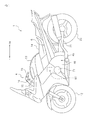
- FIG. 1 is a side view illustrating a motorcycle 1. Note that herein, “front”, “rear”, “right” and “left” mean front, rear, right and left with respect to a rider sitting on a seat 14 described later, respectively. Reference signs “F” and “Re” used in the drawings represent front and rear, respectively.
- the motorcycle 1 is an example of a straddle-type vehicle according to the present preferred embodiment.
- the motorcycle 1 is a "street type" motorcycle.
- the straddle-type vehicle according to the present teaching may be any other type of motorcycle such as an "off-road type", “scooter type", or “moped type” motorcycle, for example.
- the straddle-type vehicle according to the present teaching is not limited to the motorcycle 1.
- the straddle-type vehicle according to the present teaching may alternatively be an ATV or four-wheeler, for example.
- the motorcycle 1 preferably includes a front fork 10 and a body frame 6.
- the body frame 6 is connected with a front end portion of a rear arm 21 via a pivot shaft (not illustrated).
- the rear arm 21 is supported by the pivot shaft so as to be swingable up and down.
- a rear wheel 23 is supported by a rear end portion of the rear arm 21.
- a fuel tank 13 is disposed at an upper portion of the body frame 6.
- the seat 14 on which the rider sits is disposed rearward of the fuel tank 13.
- a handlebar 4 is provided at an upper end of the front fork 10.
- a grip 15 and a clutch lever 16 are attached to one end of the handlebar 4.
- the rider operates the clutch lever 16, thus engaging and disengaging a clutch 44 (see FIG. 2 ) via a hydraulic mechanism 51 (see FIG. 3 ) described later.
- An accelerator grip (not illustrated) and a brake lever (not illustrated) are attached to the other end of the handlebar 4.
- a front wheel 12 is rotatably provided at a lower end of the front fork 10.
- An engine 45 is an internal combustion engine in which gasoline is used as a fuel. It is to be noted that the engine 45 is not limited to an internal combustion engine such as a gasoline engine, but may be a motor engine, for example. Alternatively, the engine 45 may be a combination of a gasoline engine and a motor engine.
- the engine 45 includes a crankshaft (not illustrated).
- the crankshaft is contained in a crankcase 46.
- the crankcase 46 also contains the clutch 44 (see FIG. 2 ). Note that the crankcase 46 according to the present preferred embodiment is an example of a case according to the present teaching.
- FIG. 2 is a cross-sectional view illustrating the clutch device 40 according to the present preferred embodiment.
- the clutch device 40 includes the clutch 44, a clutch operation mechanism 50, and a clutch shaft 41.
- the clutch shaft 41 is connected to the crankshaft via the clutch 44. When the clutch 44 is engaged, the clutch shaft 41 rotates together with the crankshaft.
- the clutch shaft 41 extends in a lateral direction in FIG. 2 . In other words, the clutch shaft 41 extends in a vehicle width direction.
- the clutch device 40 is disposed at a right portion of the motorcycle 1, i.e., at a right portion of FIG. 2 .
- the clutch device 40 may be disposed at a left portion of the motorcycle 1, i.e., at a left portion of FIG. 2 .
- the clutch 44 is a wet multiplate friction clutch, for example. It is to be noted that the clutch 44 is not limited to any particular type of clutch, but may be a dry clutch or a single plate clutch.
- the clutch 44 is disposed inward of a clutch cover 71.
- the clutch cover 71 serves as a cover that defines space in which the clutch 44 is disposed.
- the clutch cover 71 is attached to the crankcase 46 (see FIG. 4 ).
- the clutch cover 71 covers the clutch 44.
- the clutch 44 preferably includes a clutch boss 72, and a clutch housing 73 disposed around the clutch boss 72.
- a plurality of friction plates 74 are provided inward of the clutch housing 73.
- a plurality of clutch plates 76 are provided outward of the clutch boss 72.
- the friction plates 74 and the clutch plates 76 are arranged alternately in an axial direction of the clutch shaft 41.
- Each friction plate 74 is engaged with the clutch housing 73.
- Each friction plate 74 is fixed to the clutch housing 73 with respect to a rotational direction of the clutch shaft 41. Therefore, the plurality of friction plates 74 rotate together with the clutch housing 73. Note that the plurality of friction plates 74 can be displaced with respect to the axial direction of the clutch shaft 41.
- the plurality of friction plates 74 are arranged in the axial direction of the clutch shaft 41.
- Each clutch plate 76 faces the associated friction plate 74 adjacent thereto. Each clutch plate 76 is engaged with the clutch boss 72. Each clutch plate 76 is fixed to the clutch boss 72 with respect to the rotational direction of the clutch shaft 41. Therefore, the plurality of clutch plates 76 rotate together with the clutch boss 72. Note that the plurality of clutch plates 76 can be displaced with respect to the axial direction of the clutch shaft 41. In the present preferred embodiment, the plurality of friction plates 74 and the plurality of clutch plates 76 constitute a plate group 78.
- a pressure plate 79 is disposed outward of the clutch shaft 41 (i.e., rightward of the clutch shaft 41 in FIG. 2 ) in the vehicle width direction.
- the pressure plate 79 is disposed outward of the plate group 78 in the vehicle width direction.
- the pressure plate 79 has a substantially disk-like shape.
- a pressing portion 79B is provided at a radially outward region of the pressure plate 79 so as to be protruded toward the plate group 78.
- the pressing portion 79B faces the rightmost friction plate 74 of the plate group 78.
- the clutch 44 is provided with a spring 81.
- the spring 81 urges the pressure plate 79 inward (i.e., leftward in FIG. 2 ) in the vehicle width direction. In other words, the spring 81 urges the pressure plate 79 in a direction in which the pressing portion 79B presses the plate group 78.
- the pressure plate 79 preferably includes a clutch release rack 82.
- the pressure plate 79 and the clutch release rack 82 are separate components. Both of the pressure plate 79 and the clutch release rack 82 are rotatable.
- the clutch release rack 82 is movable together with the pressure plate 79 in the vehicle width direction, i.e., in a longitudinal direction of the clutch release rack 82. Note that the clutch release rack 82 may be integral with the pressure plate 79.
- the clutch release rack 82 is provided with grooves 83.
- the grooves 83 may be provided at a surface of the clutch release rack 82 facing a pinion 85 of a pinion shaft 84 described later. Alternatively, the grooves 83 may be provided at both surfaces of the clutch release rack 82.
- the clutch operation mechanism 50 of the clutch device 40 preferably includes the pinion shaft 84.
- the pinion shaft 84 extends vertically. It is to be noted that the pinion shaft 84 does not necessarily have to extend vertically.
- a longitudinal direction of the pinion shaft 84 and a longitudinal direction of the clutch shaft 41 are perpendicular to each other.
- the pinion shaft 84 is perpendicular to the clutch release rack 82.
- the pinion shaft 84 is rotatable about the longitudinal direction of the pinion shaft 84.
- the pinion shaft 84 preferably includes an inner portion 84A and an outer portion 84B. The inner portion 84A of the pinion shaft 84 is covered with the clutch cover 71.
- the outer portion 84B of the pinion shaft 84 is not covered with the clutch cover 71.
- the inner portion 84A of the pinion shaft 84 is located inward of the clutch cover 71.
- the outer portion 84B of the pinion shaft 84 is located outward of the clutch cover 71.
- the pinion shaft 84 passes through the clutch cover 71.
- the pinion shaft 84 in the present preferred embodiment is an example of an operation shaft according to the present teaching.
- the pinion 85 is provided at a lower portion of the pinion shaft 84 (i.e., a lower portion thereof in FIG. 2 ).
- the pinion 85 is provided at the inner portion 84A of the pinion shaft 84.
- the pinion 85 is covered with the clutch cover 71 similarly to the inner portion 84A of the pinion shaft 84.
- the pinion 85 has a substantially disk-like shape. Grooves 86 are provided at a lateral surface of the pinion 85.
- the pinion 85 may be integral with the pinion shaft 84 as in the present preferred embodiment, or the pinion 85 and the pinion shaft 84 may alternatively be separate components.
- the grooves 86 of the pinion 85 of the pinion shaft 84 and the grooves 83 of the clutch release rack 82 intermesh with each other. Therefore, a force generated by rotation of the pinion shaft 84, i.e., rotational motion of the pinion shaft 84, is transmitted to the clutch release rack 82 via the pinion 85. Thus, a linear motion force is exerted on the clutch release rack 82, thereby moving the clutch release rack 82 in the vehicle width direction. In other words, the clutch release rack 82 moves outward of the clutch shaft 41.
- the clutch release rack 82 and the pinion 85 are disposed between the pinion shaft 84, i.e., the operation shaft, and the pressure plate 79.
- the clutch release rack 82 and the pinion 85 convert the rotational motion force of the pinion shaft 84 into the linear motion force of the clutch release rack 82.
- the pinion 85 rotates concurrently with rotation of the pinion shaft 84, and the rotational motion force of the pinion 85 is transmitted to the clutch release rack 82 due to the intermeshing of the grooves 86 of the pinion 85 and the grooves 83 of the clutch release rack 82, thus moving the clutch release rack 82 in the vehicle width direction.
- the pinion 95 is attached to an upper portion of the pinion shaft 84 (i.e., an upper portion thereof in FIG. 2 ). In other words, the pinion 95 is attached to the outer portion 84B of the pinion shaft 84. The pinion 95 is not covered with the clutch cover 71. The pinion 95 is located outward of the clutch cover 71. The pinion 95 has a substantially disk-like shape. Grooves 96 are provided at a lateral surface of the pinion 95. In the present preferred embodiment, the pinion 95 and the pinion shaft 84 are separate components. Alternatively, the pinion 95 may be integral with the pinion shaft 84.
- the pinion shaft 84 is connected to the rack 98 via the pinion 95.
- the rack 98 is disposed perpendicularly to the pinion shaft 84.
- the rack 98 is disposed in parallel with the clutch release rack 82.
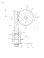
- FIG. 3 is a cross-sectional view taken along the line III-III of FIG. 2 and illustrating the rack 98, the pinion 95 and the hydraulic mechanism 51 according to the present preferred embodiment.
- the rack 98 is provided with grooves 99.
- the grooves 99 of the rack 98 may be provided only at a surface of the rack 98 facing the pinion 95, or may be provided at both surfaces of the rack 98.
- the grooves 99 of the rack 98 intermesh with the grooves 96 of the pinion 95. Therefore, a force generated by longitudinal movement of the rack 98, i.e., linear motion of the rack 98, is transmitted to the pinion shaft 84 via the pinion 95. As a result, a rotational motion force is exerted on the pinion shaft 84, thus rotating the pinion shaft 84.
- FIG. 4 is a diagram illustrating a housing 52 according to the present preferred embodiment which is attached to the clutch cover 71, with a portion of the housing 52 being cut away.
- the rack 98 and the pinion 95 are contained in the housing 52.
- the housing 52 covers the rack 98 and the pinion 95.
- the housing 52 entirely covers the rack 98 and the pinion 95, and partially covers the outer portion 84B of the pinion shaft 84.
- the housing 52 may alternatively cover only a portion of the rack 98 and a portion of the pinion 95.
- the housing 52 may alternatively cover only the rack 98. In other words, the housing 52 does not necessarily have to cover the pinion 95.
- the housing 52 consists of a single member, but may alternatively consist of two or more members.
- the rack 98 and the pinion 95 may be covered with the different members of the housing 52.
- the housing 52 does not necessarily have to be provided for a surface of the pinion 95 to which the pinion shaft 84 is attached.
- the housing 52 may be provided for only a portion of the surface of the pinion 95 to which the pinion shaft 84 is attached.
- the housing 52 is not limited to any particular shape as long as it covers the rack 98 and the pinion 95.
- the housing 52 has a rectangular cylindrical shape. Note that the housing 52 in the present preferred embodiment is an example of a container member according to the present teaching.
- a stay 54 is attached to the housing 52.
- the stay 54 serves as a member that supports the housing 52, i.e., the rack 98 and the pinion 95.
- the stay 54 may be integral with the housing 52, or may be separate from the housing 52.
- the housing 52 is attached to one end portion of the stay 54.
- the stay 54 preferably includes a first stay 54A and a second stay 54B.
- the first stay 54A is located leftward of the pinion shaft 84
- the second stay 54B is located rightward of the pinion shaft 84.
- the pinion shaft 84 is located between the first and second stays 54A and 54B.
- the stay 54 in the present preferred embodiment is an example of a support member according to the present teaching.
- the first and second stays 54A and 54B are examples of first and second support members according to the present teaching, respectively.
- An end portion of the first stay 54A is provided with a first attachment hole 55.
- An end portion of the second stay 54B is provided with a second attachment hole 56.
- the first attachment hole 55 is located leftward of the pinion shaft 84 in FIG. 4 .
- the second attachment hole 56 is located rightward of the pinion shaft 84 in FIG. 4 .
- the pinion shaft 84 is located between the first and second attachment holes 55 and 56.
- the crankcase 46 is provided with crankcase attachment holes 47 and 48.
- the clutch cover 71 is provided with clutch cover attachment holes 68 and 69. A distance between the crankcase attachment holes 47 and 48 and a distance between the clutch cover attachment holes 68 and 69 are equal to each other. Therefore, the crankcase attachment hole 47 and the clutch cover attachment hole 68 can be overlapped with each other, and the crankcase attachment hole 48 and the clutch cover attachment hole 69 can be overlapped with each other.
- Bolts 57 and 58 are each inserted into the associated attachment hole, thus fixing the crankcase 46 and the clutch cover 71 to each other. Note that the crankcase 46 and the clutch cover 71 may alternatively be fixed to each other by a different method.
- crankcase 46 and the clutch cover 71 may be fixed to each other by welding, bonding, crimping, etc.
- the crankcase 46 and the clutch cover 71 are separate components.
- the crankcase 46 and the clutch cover 71 may be integral with each other.
- a distance between the first attachment hole 55 of the first stay 54A and the second attachment hole 56 of the second stay 54B, a distance between the crankcase attachment holes 47 and 48, and a distance between the clutch cover attachment holes 68 and 69 are equal to each other. Therefore, the first attachment hole 55 of the first stay 54A and the second attachment hole 56 of the second stay 54B can be further overlapped with the above-mentioned attachment holes used for fixation of the crankcase 46 and the clutch cover 71. Hence, the first and second stays 54A and 54B can be fixed to the crankcase 46 and the clutch cover 71.
- first attachment hole 55 of the first stay 54A is overlapped with a position at which the crankcase attachment hole 47 and the clutch cover attachment hole 68 are overlapped with each other
- second attachment hole 56 of the second stay 54B is overlapped with a position at which the crankcase attachment hole 48 and the clutch cover attachment hole 69 are overlapped with each other.
- the bolts 57 and 58 are inserted into the first and second attachment holes 55 and 56, respectively, thus fixing the first and second stays 54A and 54B to the crankcase 46 and the clutch cover 71. As illustrated in FIG.
- the pinion shaft 84 is disposed between the bolts 57 and 58 when viewed in a direction perpendicular to an axial direction of the pinion shaft 84 and perpendicular to a longitudinal direction of the rack 98.
- the first and second stays 54A and 54B are fixed to the crankcase 46 and the clutch cover 71 via the bolts 57 and 58. Therefore, the first and second stays 54A and 54B can be detached by loosening the bolts 57 and 58 when necessary.
- the first and second stays 54A and 54B are detachably attached to the crankcase 46 and the clutch cover 71.
- the existing bolts by which the clutch cover 71 is fixed to the crankcase 46 are used as the bolts 57 and 58.
- the first and second stays 54A and 54B might not be fixed to the crankcase 46 and the clutch cover 71 due to insufficient lengths of the bolts.
- new bolts for fixation of the first and second stays 54A and 54B to the crankcase 46 and the clutch cover 71 may be prepared and used as the bolts 57 and 58, so that the first and second stays 54A and 54B are fixed to the crankcase 46 and the clutch cover 71.
- the bolt 57 in the present preferred embodiment is an example of a first fixture according to the present teaching
- the bolt 58 in the present preferred embodiment is an example of a second fixture according to the present teaching.
- the two stays i.e., the first and second stays 54A and 54B, constitute the stay 54, but the number of the stays constituting the stay 54 is not limited to any particular number.
- a single stay may constitute the stay 54, or three or more stays may constitute the stay 54.
- the stay 54 is fixed to the crankcase 46 and the clutch cover 71 by inserting the bolts into the two attachment holes, i.e., the first and second attachment holes 55 and 56.
- the number of the attachment holes of the stay 54 may be one, or may be three or more.
- the number of the attachment holes of the stay 54 may be set in accordance with the number of the crankcase attachment holes or the number of the clutch cover attachment holes.
- the pinion shaft 84 is located between the first and second attachment holes 55 and 56 of the stay 54. It is also contemplated that the pinion shaft 84 may be located leftward of the first and second attachment holes 55 and 56 in FIG. 4 . The pinion shaft 84 may alternatively be located rightward of the first and second attachment holes 55 and 56 in FIG. 4 .
- the stay 54 is attached to the crankcase 46 and the clutch cover 71 with the use of the bolts 57 and 58 by which the crankcase 46 and the clutch cover 71 are attached to each other. It is also contemplated that the stay 54 may be fixed to the crankcase 46 or the clutch cover 71 with the use of dedicated bolts different from the bolts 57 and 58. Note that the bolts 57 and 58 are examples of the fixtures, and therefore, the fixtures are not limited to the bolts 57 and 58. It is also contemplated that the stay 54 may be fixed to the crankcase 46 or the clutch cover 71 with the use of other fixtures such as screws, for example. The stay 54 may alternatively be fixed to the crankcase 46 or the clutch cover 71 by welding, bonding, crimping, etc.
- the rack 98 is moved by the hydraulic mechanism 51.
- the hydraulic mechanism 51 preferably includes a hydraulic cylinder 97.
- An oil tube 91 is connected to the hydraulic cylinder 97.
- the hydraulic cylinder 97 preferably includes a cylinder main body 92 and a spool 93.
- Space 94 that contains hydraulic oil is defined inside the cylinder main body 92.
- the oil tube 91 serves as a flow passage through which the hydraulic oil flows to the cylinder main body 92.
- the oil tube 91 is connected to one end of the cylinder main body 92.
- the spool 93 is inserted into the cylinder main body 92.
- the rack 98 is mounted on one end of the spool 93. In the present preferred embodiment, the spool 93 and the rack 98 are separate components.
- the hydraulic oil flows into the cylinder main body 92 through the oil tube 91.
- the spool 93 is pushed by the hydraulic oil that has flowed into the cylinder main body 92. Since the spool 93 is pushed, a force is exerted on the rack 98 in a direction A, thus moving the rack 98 in the direction A.
- the pinion 95 is rotated in a direction R because the grooves 99 of the rack 98 and the grooves 96 of the pinion 95 are intermeshing with each other.
- the hydraulic mechanism 51 may alternatively be adapted so that the rack 98 is moved in the direction A by a force that pulls the spool 93.
- the pinion 95 Upon cessation of the flow of the hydraulic oil from the oil tube 91, the pinion 95 is rotated in a direction R' opposite to the direction R as described later. Thus, a force is exerted on the rack 98 in a direction A', thereby moving the rack 98 in the direction A'. In this case, the spool 93 is pushed back due to the movement of the rack 98 in the direction A'.
- the flow of the hydraulic oil into the cylinder main body 92 is adjusted by a clutch actuator 60.
- the clutch actuator 60 preferably includes a hydraulic pump. As illustrated in FIG. 1 , the clutch actuator 60 is provided above the engine 45 and below the fuel tank 13, for example. As illustrated in FIG. 3 , the clutch actuator 60 is connected to the oil tube 91 of the hydraulic mechanism 51 and to the clutch lever 16. The clutch 44 is driven by controlling the hydraulic mechanism 51 by the clutch actuator 60.
- the clutch actuator 60 is the hydraulic pump that is driven by an electronic motor. However, a driving source for the clutch actuator 60 is not limited to an electronic motor.
- the clutch actuator 60 is operated by the clutch lever 16 in the present preferred embodiment, the clutch actuator 60 may alternatively be controlled automatically by a controller without the use of the clutch lever 16. In other words, the clutch 44 may be disengaged automatically.
- the clutch operation mechanism 50 may alternatively be adapted so that the clutch 44 is disengaged by operating the clutch lever 16 without the use of the clutch actuator 60.
- the hydraulic oil is supplied through the oil tube 91 to the space 94 surrounded by the spool 93 and the cylinder main body 92.
- the spool 93 is pushed and moved in the direction A.
- the rack 98 is also moved in the direction A, and the pinion 95 is rotated in the direction R.
- the clutch release rack 82 moves rightward in FIG. 2 via the pinion shaft 84 and the pinion 85.
- the pressure plate 79 moves rightward in FIG. 2 .
- the pressure plate 79 moves in one direction or the other direction along an axis of the clutch shaft 41 in accordance with the magnitude of a driving force of the clutch actuator 60 and an urging force of the spring 81.
- the clutch 44 is engaged or disengaged in response to the movement of the pressure plate 79.
- the clutch device 40 preferably includes: the clutch cover 71 disposed outward of the clutch 44; the pinion shaft 84 that engages and disengages the clutch 44 by being rotated; the pinion 95; the rack 98; and the hydraulic mechanism 51.
- the pinion shaft 84 preferably includes: the inner portion 84A disposed inside the clutch cover 71 and connected to the clutch 44; and the outer portion 84B disposed outside the clutch cover 71.
- the pinion 95 is provided at the outer portion 84B of the pinion shaft 84, and the grooves 96 are provided at the lateral surface of the pinion 95.
- the rack 98 preferably includes the grooves 99 that intermesh with the grooves 96 of the pinion 95.
- the hydraulic mechanism 51 moves the rack 98 in the longitudinal direction of the rack 98.
- Conventional clutch operation mechanisms include an "outer-pull-type clutch operation mechanism” and an “inner-push-type clutch operation mechanism”.
- the term “outer-pull-type clutch operation mechanism” refers to a mechanism that disengages a clutch by pulling a pressure disk with the use of a member located outward of a clutch shaft.
- the term “inner-push-type clutch operation mechanism” refers to a mechanism that disengages a clutch by pushing a pressure disk with the use of a member located inward of a clutch shaft.
- a hydraulic mechanism such as a hydraulic cylinder is used in order to solve a problem such as degradation in clutch operability resulting from wire elongation or wire degradation over time which occurs in a conventional clutch operation mechanism that uses a wire.
- Advantages of the use of a hydraulic mechanism include: an advantage that resistance to degradation over time and environmental change is achieved; an advantage that a high degree of flexibility in location is provided; and an advantage that a clutch operating force may be small compared with a clutch operation mechanism that uses a wire.
- the pinion 95 and the rack 98 are disposed outward of the clutch cover 71 and between the pinion shaft 84 and the hydraulic mechanism 51, thus making it possible to facilitate the use of the hydraulic mechanism 51 in the outer-pull-type clutch operation mechanism 50.
- the clutch operation mechanism 50 prevents problems resulting from wire elongation or wire degradation over time which occurs in using a conventional outer-pull-type clutch operation mechanism, i.e., an outer-pull-type clutch operation mechanism that uses a wire. As a result, stabilization of operability of the clutch 44 can be achieved.
- the pinion shaft 84 and the pinion 95 are separate components.
- the clutch operation mechanism 50 according to the present preferred embodiment can be fabricated by utilizing a conventional outer-pull-type clutch operation mechanism that uses a wire. Specifically, a wire-pulling operation part of a conventional outer-pull-type clutch operation mechanism is detached from a pinion shaft. Then, the pinion 95 according to the present preferred embodiment is attached to a portion of the pinion shaft from which the operation part has been detached. Subsequently, the hydraulic mechanism 51 is connected to the pinion 95 via the rack 98, thus providing the clutch operation mechanism 50 according to the present preferred embodiment.
- the clutch device 40 preferably includes the housing 52 that contains the rack 98 and the pinion 95.
- the pinion 95 is larger in width than the rack 98. Therefore, the pinion 95 is more likely to collide against other components than the rack 98. Furthermore, the intermeshing of the grooves 96 of the pinion 95 and the grooves 99 of the rack 98 might be degraded due to adhesion of dust or the like to the grooves 96 of the pinion 95 or the grooves 99 of the rack 98.
- the rack 98 and the pinion 95 are contained in the housing 52, thus making it possible to proactively prevent collision of the pinion 95 and the rack 98 against other components, and degradation in intermeshing of the grooves 96 of the pinion 95 and the grooves 99 of the rack 98 caused by dust or the like.
- the stay 54 is attached to the clutch cover 71 and the crankcase 46 with the use of the bolts 57 and 58 used for fixation of the clutch cover 71 and the crankcase 46.
- the stay 54 can be fixed to the clutch cover 71 and the crankcase 46 by utilizing the existing bolts 57 and 58 used for fixation of the clutch cover 71 and the crankcase 46.
- the stay 54 is detachably attached to the clutch cover 71 and the crankcase 46.
- the housing 52 that contains the pinion 95 and the rack 98 can be easily detached.
- the pinion shaft 84 is disposed between the bolt 57 (first fixture) and the bolt 58 (second fixture) when viewed in the direction perpendicular to the axial direction of the pinion shaft 84 and perpendicular to the longitudinal direction of the rack 98.
- the housing 52 is fixed to the crankcase 46 or the clutch cover 71 by the bolts 57 and 58 on opposite sides of the pinion shaft 84.
- the housing 52 can be fixed with stability.
- the clutch device 40 preferably includes the clutch actuator 60 that drives the hydraulic mechanism 51.
- the clutch actuator 60 drives the hydraulic mechanism 51.
- a clutch is disengaged by pulling the wire, and therefore, a large force is required to pull the wire.
- a force required for clutch disengagement can be reduced.
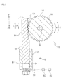
- FIG. 5 is a cross-sectional view illustrating the rack 98, the pinion 95 and the hydraulic mechanism 51 according to an alternative preferred embodiment of the present teaching.
- a portion of the spool 93 constitutes the rack 98.
- the rack 98 is provided in a portion of the spool 93 protruded from the cylinder main body 92.
Landscapes
- Engineering & Computer Science (AREA)
- General Engineering & Computer Science (AREA)
- Mechanical Engineering (AREA)
- Hydraulic Clutches, Magnetic Clutches, Fluid Clutches, And Fluid Joints (AREA)
- Transmission Devices (AREA)
- Mechanical Operated Clutches (AREA)
Abstract
Description
- The present invention relates to clutch devices and straddle-type vehicles including the clutch devices.
- A clutch device including a clutch and a clutch operation mechanism that operates the clutch is conventionally known.
- Examples of such a clutch device is disclosed in
JP-A-08-219171 JP-A-08-219171 - The pressure disk is urged inward in the axial direction of the clutch shaft by a spring. The clutch is engaged by a force of the spring. Upon pulling of the wire, the pinion shaft is rotated, and the clutch release rack moves outward in the axial direction of the clutch shaft. With this movement, the pressure disk also moves outward in the axial direction of the clutch shaft, thus disengaging the clutch. When a force that pulls the wire is lost, the pressure disk is urged inward in the axial direction of the clutch shaft by the spring. As a result, the clutch is engaged.
- A mechanism that disengages a clutch by pulling a pressure disk with the use of a member located outward of a clutch shaft in this manner will hereinafter be referred to as an "outer-pull-type clutch operation mechanism".
- Usually, a relatively large force is necessary in order to pull a pressure disk. Therefore, in a conventional clutch operation mechanism that uses a wire, the wire might unfortunately be elongated due to its long-term use, which disadvantageously causes a considerable degradation in the wire over time. A clutch device may be used in various temperature environments. In particular, a clutch device of a straddle-type vehicle is used at a high temperature during running of the vehicle in summer season, but is used at a low temperature immediately after the start of running of the vehicle in winter season. A wire might be elongated or contracted due to a significant change in temperature, and therefore, elongation of the wire must be taken into consideration. Hence, a conventional clutch operation mechanism that uses a wire still has room for improvement in terms of stabilization of clutch operability which is degraded by wire elongation or wire degradation over time.
- It is conceivable that an attempt may be made to solve the above-mentioned problems by utilizing an engine, installed on a conventional vehicle such as a two-wheeled vehicle, as it is. However, in particular, a two-wheeled vehicle or the like equipped with a conventional outer-pull-type clutch operation mechanism that uses a wire has difficulty in achieving stabilization of clutch operability while utilizing a conventional structure by changing the clutch operation mechanism into a different clutch operation mechanism that uses no wire.
- Accordingly, it is an object of the present invention to provide a clutch device including an outer-pull-type clutch operation mechanism capable of achieving stabilization of clutch operability.
- According to the present invention said object is solved by a clutch device having the features of independent claim 1. Preferred embodiments are laid down in the dependent claims.
- A clutch device according to a preferred embodiment of the present invention includes: a clutch cover; a clutch disposed inside the clutch cover; an operation shaft that includes an inner portion disposed inside the clutch cover and connected to the clutch, and an outer portion disposed outside the clutch cover, and that engages and disengages the clutch by being rotated; a pinion mounted on the outer portion of the operation shaft and provided with a groove; a rack including a groove that intermeshes with the groove of the pinion; and a hydraulic mechanism that moves the rack in a longitudinal direction of the rack.
- It is taken the idea of using, instead of a wire, a hydraulic mechanism such as a hydraulic cylinder in an outer-pull-type clutch operation mechanism, with the aim of eliminating influence of wire elongation or wire degradation over time. Advantages of the use of a hydraulic mechanism include resistance to degradation over time and environmental change. However, an outer-pull-type clutch operation mechanism includes an operation shaft that engages and disengages a clutch by being rotated. Therefore, the operation shaft has to be rotated in order to engage and disengage the clutch. Actually, a hydraulic mechanism such as a hydraulic cylinder is a mechanism that moves a component such as a spool linearly. Hence, unlike an electric motor, a hydraulic mechanism does not generate a rotational force. In view of these facts, it is provided the rack and the pinion for conversion of a linear motion into a rotational motion between the hydraulic mechanism and the operation shaft. Specifically, the pinion is provided at the outer portion of the operation shaft, and the rack including the groove that intermeshes with the groove of the pinion is moved by the hydraulic mechanism. This structure prevents problems resulting from wire elongation or wire degradation over time which occurs in a conventional outer-pull-type clutch operation mechanism, i.e., an outer-pull-type clutch operation mechanism that uses a wire. Consequently, stabilization of clutch operability can be achieved. Furthermore, the rack and the pinion are disposed outward of the clutch cover, thus allowing the operation shaft to be rotated by the hydraulic mechanism that exerts a linear force. As a result, the hydraulic mechanism can be easily used in an outer-pull-type clutch operation mechanism.
- According to one preferred embodiment of the present teaching, the clutch device preferably includes a container member that contains the rack and the pinion.
- The pinion is larger in width than the rack. Therefore, the pinion is more likely to collide against other components than the rack. Furthermore, the intermeshing of the groove of the pinion and the groove of the rack might be degraded due to adhesion of dust or the like to the groove of the pinion or the groove of the rack. To cope with this, the rack and the pinion are contained in the container member, thus making it possible to proactively prevent collision of the pinion and the rack against other components, and degradation in intermeshing of the groove of the pinion and the groove of the rack caused by dust or the like.
- According to another preferred embodiment of the present teaching, the clutch cover is preferably provided with an attachment hole. The clutch device preferably includes: a case that contains the clutch and is provided with an attachment hole; a fixture that is inserted into the attachment hole of the clutch cover and the attachment hole of the case, thus attaching the clutch cover to the case; and a support member that is attached to the container member or integral with the container member, thus supporting the container member. The support member is preferably provided with an attachment hole into which the fixture is to be inserted. The fixture is preferably inserted into the attachment hole of the clutch cover, the attachment hole of the case and the attachment hole of the support member, thus attaching the support member to the case along with the clutch cover.
- Thus, the support member can be attached to the clutch cover or the case by utilizing the existing attachment holes used for attachment of the clutch cover to the case and by inserting the fixture into the attachment holes.
- According to still another embodiment of the present teaching, the clutch device preferably includes: a case that contains the clutch; and a support member that is attached to the container member or integral with the container member, thus supporting the container member. The support member is preferably detachably attached to at least one of the clutch cover and the case.
- By detachably attaching the support member to at least one of the clutch cover and the case, the container member that contains the pinion and the rack can be easily detached when maintenance is performed on the pinion or the rack or when the pinion or the rack is broken.
- According to yet another preferred embodiment of the present teaching, the clutch device preferably includes: first and second support members that are attached to the container member or integral with the container member, thus supporting the container member; a first fixture for attachment of the first support member to the case or the clutch cover; and a second fixture for attachment of the second support member to the case or the clutch cover. The operation shaft is preferably disposed between the first and second fixtures when viewed in a direction perpendicular to an axial direction of the operation shaft and perpendicular to the longitudinal direction of the rack.
- The container member is fixed to the case or the clutch cover by the first and second fixtures on opposite sides of the operation shaft. Hence, the container member can be fixed with stability.
- According to still yet another preferred embodiment of the present teaching, the hydraulic mechanism preferably includes a cylinder main body, and a spool inserted into the cylinder main body. A portion of the spool preferably constitutes the rack.
- Thus, since a portion of the spool of the hydraulic mechanism constitutes the rack, the number of components is reduced as compared with a case where a rack separate from the spool is attached to the spool, and in addition, the clutch device according to the present teaching can be easily fabricated.
- According to another preferred embodiment of the present teaching, the clutch device preferably includes an actuator that drives the hydraulic mechanism.
- In a conventional outer-pull-type clutch operation mechanism that uses a wire as in
JP-A-08-219171 - According to still another preferred embodiment of the present teaching, there is provided a straddle-type vehicle including the clutch device according to one of the preferred embodiments of the present teaching described above.
- Thus, there is provided the straddle-type vehicle including the clutch device that includes an outer-pull-type clutch operation mechanism capable of improving clutch operability as described above.
- Various embodiments of the present invention provide a clutch device including an outer-pull-type clutch operation mechanism capable of improving clutch operability.
-
-
FIG. 1 is a side view of a motorcycle according to a first preferred embodiment of the present teaching. -
FIG. 2 is a cross-sectional view illustrating a clutch device according to the first preferred embodiment. -
FIG. 3 is a cross-sectional view taken along the line III-III ofFIG. 2 and illustrating a rack, a pinion and a hydraulic mechanism according to the first preferred embodiment. -
FIG. 4 is a diagram illustrating a housing according to the first preferred embodiment which is attached to a clutch cover, with a portion of the housing being cut away. -
FIG. 5 is a cross-sectional view illustrating a rack, a pinion and a hydraulic mechanism according to an alternative preferred embodiment of the present teaching. - Hereinafter, preferred embodiments of the present teaching will be described. Note that matters which are other than those particularly mentioned herein and are necessary to carry out the present teaching may be grasped as set items by those skilled in the art on the basis of conventional techniques in this field. The present teaching may be carried out on the basis of contents disclosed herein and technical common knowledge in this field.
- Hereinafter, a motorcycle including a clutch device according to the present teaching will be described with reference to the drawings.
FIG. 1 is a side view illustrating a motorcycle 1. Note that herein, "front", "rear", "right" and "left" mean front, rear, right and left with respect to a rider sitting on aseat 14 described later, respectively. Reference signs "F" and "Re" used in the drawings represent front and rear, respectively. - The motorcycle 1 is an example of a straddle-type vehicle according to the present preferred embodiment. The motorcycle 1 is a "street type" motorcycle. Note that the straddle-type vehicle according to the present teaching may be any other type of motorcycle such as an "off-road type", "scooter type", or "moped type" motorcycle, for example. In other words, the straddle-type vehicle according to the present teaching is not limited to the motorcycle 1. The straddle-type vehicle according to the present teaching may alternatively be an ATV or four-wheeler, for example.
- As illustrated in
FIG. 1 , the motorcycle 1 preferably includes afront fork 10 and abody frame 6. Thebody frame 6 is connected with a front end portion of arear arm 21 via a pivot shaft (not illustrated). Therear arm 21 is supported by the pivot shaft so as to be swingable up and down. Arear wheel 23 is supported by a rear end portion of therear arm 21. - A
fuel tank 13 is disposed at an upper portion of thebody frame 6. Theseat 14 on which the rider sits is disposed rearward of thefuel tank 13. - A
handlebar 4 is provided at an upper end of thefront fork 10. Agrip 15 and aclutch lever 16 are attached to one end of thehandlebar 4. The rider operates theclutch lever 16, thus engaging and disengaging a clutch 44 (seeFIG. 2 ) via a hydraulic mechanism 51 (seeFIG. 3 ) described later. An accelerator grip (not illustrated) and a brake lever (not illustrated) are attached to the other end of thehandlebar 4. Afront wheel 12 is rotatably provided at a lower end of thefront fork 10. - An
engine 45 according to the present preferred embodiment is an internal combustion engine in which gasoline is used as a fuel. It is to be noted that theengine 45 is not limited to an internal combustion engine such as a gasoline engine, but may be a motor engine, for example. Alternatively, theengine 45 may be a combination of a gasoline engine and a motor engine. - The
engine 45 includes a crankshaft (not illustrated). The crankshaft is contained in acrankcase 46. Thecrankcase 46 also contains the clutch 44 (seeFIG. 2 ). Note that thecrankcase 46 according to the present preferred embodiment is an example of a case according to the present teaching. - Next, a
clutch device 40 according to the present preferred embodiment will be described.FIG. 2 is a cross-sectional view illustrating theclutch device 40 according to the present preferred embodiment. As illustrated inFIG. 2 , theclutch device 40 includes the clutch 44, aclutch operation mechanism 50, and aclutch shaft 41. Theclutch shaft 41 is connected to the crankshaft via the clutch 44. When the clutch 44 is engaged, theclutch shaft 41 rotates together with the crankshaft. Theclutch shaft 41 extends in a lateral direction inFIG. 2 . In other words, theclutch shaft 41 extends in a vehicle width direction. Note that in the present preferred embodiment, theclutch device 40 is disposed at a right portion of the motorcycle 1, i.e., at a right portion ofFIG. 2 . Alternatively, theclutch device 40 may be disposed at a left portion of the motorcycle 1, i.e., at a left portion ofFIG. 2 . - The clutch 44 according to the present preferred embodiment is a wet multiplate friction clutch, for example. It is to be noted that the clutch 44 is not limited to any particular type of clutch, but may be a dry clutch or a single plate clutch. The clutch 44 is disposed inward of a
clutch cover 71. Theclutch cover 71 serves as a cover that defines space in which the clutch 44 is disposed. Theclutch cover 71 is attached to the crankcase 46 (seeFIG. 4 ). Theclutch cover 71 covers the clutch 44. The clutch 44 preferably includes aclutch boss 72, and aclutch housing 73 disposed around theclutch boss 72. A plurality offriction plates 74 are provided inward of theclutch housing 73. A plurality ofclutch plates 76 are provided outward of theclutch boss 72. Thefriction plates 74 and theclutch plates 76 are arranged alternately in an axial direction of theclutch shaft 41. - Each
friction plate 74 is engaged with theclutch housing 73. Eachfriction plate 74 is fixed to theclutch housing 73 with respect to a rotational direction of theclutch shaft 41. Therefore, the plurality offriction plates 74 rotate together with theclutch housing 73. Note that the plurality offriction plates 74 can be displaced with respect to the axial direction of theclutch shaft 41. The plurality offriction plates 74 are arranged in the axial direction of theclutch shaft 41. - Each
clutch plate 76 faces the associatedfriction plate 74 adjacent thereto. Eachclutch plate 76 is engaged with theclutch boss 72. Eachclutch plate 76 is fixed to theclutch boss 72 with respect to the rotational direction of theclutch shaft 41. Therefore, the plurality ofclutch plates 76 rotate together with theclutch boss 72. Note that the plurality ofclutch plates 76 can be displaced with respect to the axial direction of theclutch shaft 41. In the present preferred embodiment, the plurality offriction plates 74 and the plurality ofclutch plates 76 constitute aplate group 78. - As illustrated in
FIG. 2 , apressure plate 79 is disposed outward of the clutch shaft 41 (i.e., rightward of theclutch shaft 41 inFIG. 2 ) in the vehicle width direction. Thepressure plate 79 is disposed outward of theplate group 78 in the vehicle width direction. Thepressure plate 79 has a substantially disk-like shape. Apressing portion 79B is provided at a radially outward region of thepressure plate 79 so as to be protruded toward theplate group 78. Thepressing portion 79B faces therightmost friction plate 74 of theplate group 78. - The clutch 44 is provided with a
spring 81. Thespring 81 urges thepressure plate 79 inward (i.e., leftward inFIG. 2 ) in the vehicle width direction. In other words, thespring 81 urges thepressure plate 79 in a direction in which thepressing portion 79B presses theplate group 78. - The
pressure plate 79 preferably includes aclutch release rack 82. Thepressure plate 79 and theclutch release rack 82 are separate components. Both of thepressure plate 79 and theclutch release rack 82 are rotatable. Theclutch release rack 82 is movable together with thepressure plate 79 in the vehicle width direction, i.e., in a longitudinal direction of theclutch release rack 82. Note that theclutch release rack 82 may be integral with thepressure plate 79. Theclutch release rack 82 is provided withgrooves 83. Thegrooves 83 may be provided at a surface of theclutch release rack 82 facing apinion 85 of apinion shaft 84 described later. Alternatively, thegrooves 83 may be provided at both surfaces of theclutch release rack 82. - The
clutch operation mechanism 50 of theclutch device 40 preferably includes thepinion shaft 84. Thepinion shaft 84 extends vertically. It is to be noted that thepinion shaft 84 does not necessarily have to extend vertically. A longitudinal direction of thepinion shaft 84 and a longitudinal direction of theclutch shaft 41 are perpendicular to each other. Thepinion shaft 84 is perpendicular to theclutch release rack 82. Thepinion shaft 84 is rotatable about the longitudinal direction of thepinion shaft 84. Thepinion shaft 84 preferably includes aninner portion 84A and anouter portion 84B. Theinner portion 84A of thepinion shaft 84 is covered with theclutch cover 71. Theouter portion 84B of thepinion shaft 84 is not covered with theclutch cover 71. Theinner portion 84A of thepinion shaft 84 is located inward of theclutch cover 71. Theouter portion 84B of thepinion shaft 84 is located outward of theclutch cover 71. In other words, thepinion shaft 84 passes through theclutch cover 71. Note that thepinion shaft 84 in the present preferred embodiment is an example of an operation shaft according to the present teaching. - The
pinion 85 is provided at a lower portion of the pinion shaft 84 (i.e., a lower portion thereof inFIG. 2 ). In other words, thepinion 85 is provided at theinner portion 84A of thepinion shaft 84. Thepinion 85 is covered with theclutch cover 71 similarly to theinner portion 84A of thepinion shaft 84. Thepinion 85 has a substantially disk-like shape.Grooves 86 are provided at a lateral surface of thepinion 85. Note that thepinion 85 may be integral with thepinion shaft 84 as in the present preferred embodiment, or thepinion 85 and thepinion shaft 84 may alternatively be separate components. - The
grooves 86 of thepinion 85 of thepinion shaft 84 and thegrooves 83 of theclutch release rack 82 intermesh with each other. Therefore, a force generated by rotation of thepinion shaft 84, i.e., rotational motion of thepinion shaft 84, is transmitted to theclutch release rack 82 via thepinion 85. Thus, a linear motion force is exerted on theclutch release rack 82, thereby moving theclutch release rack 82 in the vehicle width direction. In other words, theclutch release rack 82 moves outward of theclutch shaft 41. In this preferred embodiment, theclutch release rack 82 and thepinion 85 are disposed between thepinion shaft 84, i.e., the operation shaft, and thepressure plate 79. Theclutch release rack 82 and thepinion 85 convert the rotational motion force of thepinion shaft 84 into the linear motion force of theclutch release rack 82. Specifically, thepinion 85 rotates concurrently with rotation of thepinion shaft 84, and the rotational motion force of thepinion 85 is transmitted to theclutch release rack 82 due to the intermeshing of thegrooves 86 of thepinion 85 and thegrooves 83 of theclutch release rack 82, thus moving theclutch release rack 82 in the vehicle width direction. Note that in the present preferred embodiment, there are provided two rack-and-pinion mechanisms, one of which is made up of theclutch release rack 82 and thepinion 85 and the other one of which is made up of arack 98 and apinion 95 described below. - The
pinion 95 is attached to an upper portion of the pinion shaft 84 (i.e., an upper portion thereof inFIG. 2 ). In other words, thepinion 95 is attached to theouter portion 84B of thepinion shaft 84. Thepinion 95 is not covered with theclutch cover 71. Thepinion 95 is located outward of theclutch cover 71. Thepinion 95 has a substantially disk-like shape.Grooves 96 are provided at a lateral surface of thepinion 95. In the present preferred embodiment, thepinion 95 and thepinion shaft 84 are separate components. Alternatively, thepinion 95 may be integral with thepinion shaft 84. - The
pinion shaft 84 is connected to therack 98 via thepinion 95. Therack 98 is disposed perpendicularly to thepinion shaft 84. Therack 98 is disposed in parallel with theclutch release rack 82. -
FIG. 3 is a cross-sectional view taken along the line III-III ofFIG. 2 and illustrating therack 98, thepinion 95 and thehydraulic mechanism 51 according to the present preferred embodiment. As illustrated inFIG. 3 , therack 98 is provided withgrooves 99. Thegrooves 99 of therack 98 may be provided only at a surface of therack 98 facing thepinion 95, or may be provided at both surfaces of therack 98. Thegrooves 99 of therack 98 intermesh with thegrooves 96 of thepinion 95. Therefore, a force generated by longitudinal movement of therack 98, i.e., linear motion of therack 98, is transmitted to thepinion shaft 84 via thepinion 95. As a result, a rotational motion force is exerted on thepinion shaft 84, thus rotating thepinion shaft 84. -
FIG. 4 is a diagram illustrating ahousing 52 according to the present preferred embodiment which is attached to theclutch cover 71, with a portion of thehousing 52 being cut away. As illustrated inFIG. 4 , therack 98 and thepinion 95 are contained in thehousing 52. Thehousing 52 covers therack 98 and thepinion 95. In the present preferred embodiment, thehousing 52 entirely covers therack 98 and thepinion 95, and partially covers theouter portion 84B of thepinion shaft 84. Thehousing 52 may alternatively cover only a portion of therack 98 and a portion of thepinion 95. Thehousing 52 may alternatively cover only therack 98. In other words, thehousing 52 does not necessarily have to cover thepinion 95. In the present preferred embodiment, thehousing 52 consists of a single member, but may alternatively consist of two or more members. When thehousing 52 consists of two members, therack 98 and thepinion 95 may be covered with the different members of thehousing 52. Thehousing 52 does not necessarily have to be provided for a surface of thepinion 95 to which thepinion shaft 84 is attached. Thehousing 52 may be provided for only a portion of the surface of thepinion 95 to which thepinion shaft 84 is attached. Thehousing 52 is not limited to any particular shape as long as it covers therack 98 and thepinion 95. For example, thehousing 52 has a rectangular cylindrical shape. Note that thehousing 52 in the present preferred embodiment is an example of a container member according to the present teaching. - As illustrated in
FIG. 4 , astay 54 is attached to thehousing 52. Thestay 54 serves as a member that supports thehousing 52, i.e., therack 98 and thepinion 95. Thestay 54 may be integral with thehousing 52, or may be separate from thehousing 52. In the present preferred embodiment, thehousing 52 is attached to one end portion of thestay 54. Thestay 54 preferably includes afirst stay 54A and asecond stay 54B. InFIG. 4 , thefirst stay 54A is located leftward of thepinion shaft 84, and thesecond stay 54B is located rightward of thepinion shaft 84. Thepinion shaft 84 is located between the first andsecond stays stay 54 in the present preferred embodiment is an example of a support member according to the present teaching. The first andsecond stays - An end portion of the
first stay 54A is provided with afirst attachment hole 55. An end portion of thesecond stay 54B is provided with asecond attachment hole 56. Thefirst attachment hole 55 is located leftward of thepinion shaft 84 inFIG. 4 . Thesecond attachment hole 56 is located rightward of thepinion shaft 84 inFIG. 4 . Thepinion shaft 84 is located between the first and second attachment holes 55 and 56. - The
crankcase 46 is provided with crankcase attachment holes 47 and 48. Theclutch cover 71 is provided with clutch cover attachment holes 68 and 69. A distance between the crankcase attachment holes 47 and 48 and a distance between the clutch cover attachment holes 68 and 69 are equal to each other. Therefore, thecrankcase attachment hole 47 and the clutchcover attachment hole 68 can be overlapped with each other, and thecrankcase attachment hole 48 and the clutchcover attachment hole 69 can be overlapped with each other.Bolts crankcase 46 and theclutch cover 71 to each other. Note that thecrankcase 46 and theclutch cover 71 may alternatively be fixed to each other by a different method. For example, thecrankcase 46 and theclutch cover 71 may be fixed to each other by welding, bonding, crimping, etc. In the present preferred embodiment, thecrankcase 46 and theclutch cover 71 are separate components. Alternatively, thecrankcase 46 and theclutch cover 71 may be integral with each other. - In the present preferred embodiment, a distance between the
first attachment hole 55 of thefirst stay 54A and thesecond attachment hole 56 of thesecond stay 54B, a distance between the crankcase attachment holes 47 and 48, and a distance between the clutch cover attachment holes 68 and 69 are equal to each other. Therefore, thefirst attachment hole 55 of thefirst stay 54A and thesecond attachment hole 56 of thesecond stay 54B can be further overlapped with the above-mentioned attachment holes used for fixation of thecrankcase 46 and theclutch cover 71. Hence, the first andsecond stays crankcase 46 and theclutch cover 71. Specifically, thefirst attachment hole 55 of thefirst stay 54A is overlapped with a position at which thecrankcase attachment hole 47 and the clutchcover attachment hole 68 are overlapped with each other, and in addition, thesecond attachment hole 56 of thesecond stay 54B is overlapped with a position at which thecrankcase attachment hole 48 and the clutchcover attachment hole 69 are overlapped with each other. Then, thebolts second stays crankcase 46 and theclutch cover 71. As illustrated inFIG. 4 , thepinion shaft 84 is disposed between thebolts pinion shaft 84 and perpendicular to a longitudinal direction of therack 98. As described above, the first andsecond stays crankcase 46 and theclutch cover 71 via thebolts second stays bolts second stays crankcase 46 and theclutch cover 71. Note that in the present preferred embodiment, the existing bolts by which theclutch cover 71 is fixed to thecrankcase 46 are used as thebolts second stays crankcase 46 and theclutch cover 71 due to insufficient lengths of the bolts. In that case, new bolts for fixation of the first andsecond stays crankcase 46 and theclutch cover 71 may be prepared and used as thebolts second stays crankcase 46 and theclutch cover 71. Note that thebolt 57 in the present preferred embodiment is an example of a first fixture according to the present teaching, and thebolt 58 in the present preferred embodiment is an example of a second fixture according to the present teaching. - Note that in the present preferred embodiment, the two stays, i.e., the first and
second stays stay 54, but the number of the stays constituting thestay 54 is not limited to any particular number. For example, a single stay may constitute thestay 54, or three or more stays may constitute thestay 54. In the present preferred embodiment, thestay 54 is fixed to thecrankcase 46 and theclutch cover 71 by inserting the bolts into the two attachment holes, i.e., the first and second attachment holes 55 and 56. Alternatively, the number of the attachment holes of thestay 54 may be one, or may be three or more. The number of the attachment holes of thestay 54 may be set in accordance with the number of the crankcase attachment holes or the number of the clutch cover attachment holes. In the present preferred embodiment, thepinion shaft 84 is located between the first and second attachment holes 55 and 56 of thestay 54. It is also contemplated that thepinion shaft 84 may be located leftward of the first and second attachment holes 55 and 56 inFIG. 4 . Thepinion shaft 84 may alternatively be located rightward of the first and second attachment holes 55 and 56 inFIG. 4 . - In the present preferred embodiment, the
stay 54 is attached to thecrankcase 46 and theclutch cover 71 with the use of thebolts crankcase 46 and theclutch cover 71 are attached to each other. It is also contemplated that thestay 54 may be fixed to thecrankcase 46 or theclutch cover 71 with the use of dedicated bolts different from thebolts bolts bolts stay 54 may be fixed to thecrankcase 46 or theclutch cover 71 with the use of other fixtures such as screws, for example. Thestay 54 may alternatively be fixed to thecrankcase 46 or theclutch cover 71 by welding, bonding, crimping, etc. - In the
clutch device 40 according to the present preferred embodiment, therack 98 is moved by thehydraulic mechanism 51. As illustrated inFIG. 3 , thehydraulic mechanism 51 preferably includes ahydraulic cylinder 97. Anoil tube 91 is connected to thehydraulic cylinder 97. Thehydraulic cylinder 97 preferably includes a cylindermain body 92 and aspool 93.Space 94 that contains hydraulic oil is defined inside the cylindermain body 92. Theoil tube 91 serves as a flow passage through which the hydraulic oil flows to the cylindermain body 92. Theoil tube 91 is connected to one end of the cylindermain body 92. Thespool 93 is inserted into the cylindermain body 92. Therack 98 is mounted on one end of thespool 93. In the present preferred embodiment, thespool 93 and therack 98 are separate components. - In the
hydraulic mechanism 51, the hydraulic oil flows into the cylindermain body 92 through theoil tube 91. Thespool 93 is pushed by the hydraulic oil that has flowed into the cylindermain body 92. Since thespool 93 is pushed, a force is exerted on therack 98 in a direction A, thus moving therack 98 in the direction A. In this case, thepinion 95 is rotated in a direction R because thegrooves 99 of therack 98 and thegrooves 96 of thepinion 95 are intermeshing with each other. Note that although therack 98 is moved in the direction A by a force that pushes thespool 93 in the present preferred embodiment, thehydraulic mechanism 51 may alternatively be adapted so that therack 98 is moved in the direction A by a force that pulls thespool 93. - Upon cessation of the flow of the hydraulic oil from the
oil tube 91, thepinion 95 is rotated in a direction R' opposite to the direction R as described later. Thus, a force is exerted on therack 98 in a direction A', thereby moving therack 98 in the direction A'. In this case, thespool 93 is pushed back due to the movement of therack 98 in the direction A'. - In the present preferred embodiment, the flow of the hydraulic oil into the cylinder
main body 92 is adjusted by aclutch actuator 60. In the present preferred embodiment, theclutch actuator 60 preferably includes a hydraulic pump. As illustrated inFIG. 1 , theclutch actuator 60 is provided above theengine 45 and below thefuel tank 13, for example. As illustrated inFIG. 3 , theclutch actuator 60 is connected to theoil tube 91 of thehydraulic mechanism 51 and to theclutch lever 16. The clutch 44 is driven by controlling thehydraulic mechanism 51 by theclutch actuator 60. In the present preferred embodiment, theclutch actuator 60 is the hydraulic pump that is driven by an electronic motor. However, a driving source for theclutch actuator 60 is not limited to an electronic motor. Although theclutch actuator 60 is operated by theclutch lever 16 in the present preferred embodiment, theclutch actuator 60 may alternatively be controlled automatically by a controller without the use of theclutch lever 16. In other words, the clutch 44 may be disengaged automatically. Theclutch operation mechanism 50 may alternatively be adapted so that the clutch 44 is disengaged by operating theclutch lever 16 without the use of theclutch actuator 60. - Upon driving of the
clutch actuator 60, the hydraulic oil is supplied through theoil tube 91 to thespace 94 surrounded by thespool 93 and the cylindermain body 92. As mentioned above, upon supply of the hydraulic oil to thespace 94, thespool 93 is pushed and moved in the direction A. Thus, therack 98 is also moved in the direction A, and thepinion 95 is rotated in the direction R. Then, as illustrated inFIG. 2 , theclutch release rack 82 moves rightward inFIG. 2 via thepinion shaft 84 and thepinion 85. When theclutch release rack 82 is pulled rightward inFIG. 2 , thepressure plate 79 moves rightward inFIG. 2 . Consequently, thepressing portion 79B of thepressure plate 79 goes away from theplate group 78. With thepressing portion 79B located away from theplate group 78, eachfriction plate 74 and the associatedclutch plate 76 are not pressed against each other. A slight gap is provided between eachfriction plate 74 and the associatedclutch plate 76. Therefore, a frictional force that enables transmission of a driving force is not generated between eachfriction plate 74 and the associatedclutch plate 76. As a result, the clutch 44 is disengaged. - Conversely, when the clutch 44 is engaged, a force that pulls the
pressure plate 79 is lost, so that thepressure plate 79 is moved leftward inFIG. 2 by thespring 81. Upon leftward movement of thepressure plate 79 inFIG. 2 , thepressing portion 79B presses theplate group 78 leftward. Therefore, thefriction plates 74 and theclutch plates 76 of theplate group 78 are pressed against each other. As a result, the clutch 44 is engaged. Upon leftward movement of thepressure plate 79 inFIG. 2 , theclutch release rack 82 also moves leftward inFIG. 2 . Then, as illustrated inFIG. 3 , thepinion 95 is rotated in the direction R' via thepinion 85 and thepinion shaft 84. In accordance with the rotation of thepinion 95 in the direction R', therack 98 moves in the direction A'. Thespool 93 is pushed back by the movement of therack 98 in the direction A'. - Thus, the
pressure plate 79 moves in one direction or the other direction along an axis of theclutch shaft 41 in accordance with the magnitude of a driving force of theclutch actuator 60 and an urging force of thespring 81. The clutch 44 is engaged or disengaged in response to the movement of thepressure plate 79. - As described above, the
clutch device 40 according to the present preferred embodiment preferably includes: theclutch cover 71 disposed outward of the clutch 44; thepinion shaft 84 that engages and disengages the clutch 44 by being rotated; thepinion 95; therack 98; and thehydraulic mechanism 51. Thepinion shaft 84 preferably includes: theinner portion 84A disposed inside theclutch cover 71 and connected to the clutch 44; and theouter portion 84B disposed outside theclutch cover 71. Thepinion 95 is provided at theouter portion 84B of thepinion shaft 84, and thegrooves 96 are provided at the lateral surface of thepinion 95. Therack 98 preferably includes thegrooves 99 that intermesh with thegrooves 96 of thepinion 95. Thehydraulic mechanism 51 moves therack 98 in the longitudinal direction of therack 98. - Conventional clutch operation mechanisms include an "outer-pull-type clutch operation mechanism" and an "inner-push-type clutch operation mechanism". As mentioned above, the term "outer-pull-type clutch operation mechanism" refers to a mechanism that disengages a clutch by pulling a pressure disk with the use of a member located outward of a clutch shaft. Meanwhile, the term "inner-push-type clutch operation mechanism" refers to a mechanism that disengages a clutch by pushing a pressure disk with the use of a member located inward of a clutch shaft. In an inner-push-type clutch operation mechanism, a hydraulic mechanism such as a hydraulic cylinder is used in order to solve a problem such as degradation in clutch operability resulting from wire elongation or wire degradation over time which occurs in a conventional clutch operation mechanism that uses a wire. Advantages of the use of a hydraulic mechanism include: an advantage that resistance to degradation over time and environmental change is achieved; an advantage that a high degree of flexibility in location is provided; and an advantage that a clutch operating force may be small compared with a clutch operation mechanism that uses a wire.
- However, in a conventional outer-pull-type clutch operation mechanism that uses a wire, it is difficult to use a hydraulic mechanism instead of a wire. In a conventional outer-pull-type clutch operation mechanism that uses a wire, a clutch is disengaged by utilizing a rotational motion force of a pinion shaft (operation shaft). A hydraulic mechanism is a mechanism that utilizes a force of hydraulic oil by which a spool is pushed, i.e., a linear motion force. Hence, it is difficult to use a hydraulic mechanism in an outer-pull-type clutch operation mechanism because it is inherently necessary to convert a linear motion force into a rotational motion force. However, as in the present preferred embodiment, the
pinion 95 and therack 98 are disposed outward of theclutch cover 71 and between thepinion shaft 84 and thehydraulic mechanism 51, thus making it possible to facilitate the use of thehydraulic mechanism 51 in the outer-pull-typeclutch operation mechanism 50. - The
clutch operation mechanism 50 according to the present preferred embodiment prevents problems resulting from wire elongation or wire degradation over time which occurs in using a conventional outer-pull-type clutch operation mechanism, i.e., an outer-pull-type clutch operation mechanism that uses a wire. As a result, stabilization of operability of the clutch 44 can be achieved. - In a conventional outer-pull-type clutch operation mechanism that uses a wire, an operation shaft is rotated by a wire, and therefore, a clutch is disengaged by pulling the wire. The wire is moved while being pulled. Hence, such a conventional clutch operation mechanism requires space for placement of the wire and movement space for pulling of the wire. However, in the outer-pull-type clutch operation mechanism that uses the
hydraulic mechanism 51 according to the present preferred embodiment, only therack 98 is moved linearly by thehydraulic mechanism 51 in order to rotate the operation shaft (pinion shaft), and therefore, no space for movement of thehydraulic mechanism 51 is required. - In the present preferred embodiment, the
pinion shaft 84 and thepinion 95 are separate components. Thus, theclutch operation mechanism 50 according to the present preferred embodiment can be fabricated by utilizing a conventional outer-pull-type clutch operation mechanism that uses a wire. Specifically, a wire-pulling operation part of a conventional outer-pull-type clutch operation mechanism is detached from a pinion shaft. Then, thepinion 95 according to the present preferred embodiment is attached to a portion of the pinion shaft from which the operation part has been detached. Subsequently, thehydraulic mechanism 51 is connected to thepinion 95 via therack 98, thus providing theclutch operation mechanism 50 according to the present preferred embodiment. - As illustrated in
FIG. 4 , in the present preferred embodiment, theclutch device 40 preferably includes thehousing 52 that contains therack 98 and thepinion 95. Thepinion 95 is larger in width than therack 98. Therefore, thepinion 95 is more likely to collide against other components than therack 98. Furthermore, the intermeshing of thegrooves 96 of thepinion 95 and thegrooves 99 of therack 98 might be degraded due to adhesion of dust or the like to thegrooves 96 of thepinion 95 or thegrooves 99 of therack 98. To cope with this, therack 98 and thepinion 95 are contained in thehousing 52, thus making it possible to proactively prevent collision of thepinion 95 and therack 98 against other components, and degradation in intermeshing of thegrooves 96 of thepinion 95 and thegrooves 99 of therack 98 caused by dust or the like. - In the present preferred embodiment, the
stay 54 is attached to theclutch cover 71 and thecrankcase 46 with the use of thebolts clutch cover 71 and thecrankcase 46. Thus, thestay 54 can be fixed to theclutch cover 71 and thecrankcase 46 by utilizing the existingbolts clutch cover 71 and thecrankcase 46. - In the present preferred embodiment, the
stay 54 is detachably attached to theclutch cover 71 and thecrankcase 46. Thus, for example, when maintenance is performed on thepinion 95 or therack 98 or when thepinion 95 or therack 98 is broken, thehousing 52 that contains thepinion 95 and therack 98 can be easily detached. - In the present preferred embodiment, as illustrated in
FIG. 4 , thepinion shaft 84 is disposed between the bolt 57 (first fixture) and the bolt 58 (second fixture) when viewed in the direction perpendicular to the axial direction of thepinion shaft 84 and perpendicular to the longitudinal direction of therack 98. Thus, thehousing 52 is fixed to thecrankcase 46 or theclutch cover 71 by thebolts pinion shaft 84. Hence, thehousing 52 can be fixed with stability. - In the present preferred embodiment, the
clutch device 40 preferably includes theclutch actuator 60 that drives thehydraulic mechanism 51. In a conventional outer-pull-type clutch operation mechanism that uses a wire, a clutch is disengaged by pulling the wire, and therefore, a large force is required to pull the wire. However, when thehydraulic mechanism 51 is driven by theclutch actuator 60 as in the present preferred embodiment, a force required for clutch disengagement can be reduced. - The
rack 98 and thespool 93 of thehydraulic mechanism 51 are separate components in the first preferred embodiment. Alternatively, therack 98 and thespool 93 of thehydraulic mechanism 51 may be integral with each other.FIG. 5 is a cross-sectional view illustrating therack 98, thepinion 95 and thehydraulic mechanism 51 according to an alternative preferred embodiment of the present teaching. As illustrated inFIG. 5 , a portion of thespool 93 constitutes therack 98. Specifically, therack 98 is provided in a portion of thespool 93 protruded from the cylindermain body 92. Thus, the number of components is reduced as compared with a case where therack 98 separate from thespool 93 is attached to thespool 93, and in addition, theclutch device 40 according to the present teaching can be easily fabricated. -
- 1
- motorcycle (straddle-type vehicle)
- 40
- clutch device
- 44
- clutch
- 50
- clutch operation mechanism
- 51
- hydraulic mechanism
- 52
- housing (container member)
- 54
- stay (support member)
- 57
- bolt (first fixture)
- 58
- bolt (second fixture)
- 71
- clutch cover
- 84
- pinion shaft (operation shaft)
- 95
- pinion
- 98
- rack
Claims (9)
- A clutch device comprising:a clutch cover (71);a clutch (44) disposed inside the clutch cover (71);an operation shaft (84) that comprises an inner portion disposed inside the clutch cover (71) and connected to the clutch (44), and an outer portion disposed outside the clutch cover (71), and that engages and disengages the clutch (44) by being rotated;a pinion (95) mounted on the outer portion of the operation shaft (84) andprovided with a groove (96);a rack (98) comprising a groove (99) that intermeshes with the groove (96) of the pinion (95); anda hydraulic mechanism (51) that moves the rack (98) in a longitudinal direction of the rack (98).
- A clutch device according to claim 1, further comprising a container member (52) that contains the rack (98) and the pinion (95).
- A clutch device according to claim 2, further comprising a case (46) that contains the clutch (44); and
at least one support member (54,54A,54B) that is attached to the container member (52) or integral with the container member (52), thus supporting the container member (52). - A clutch device according to claim 3, wherein the support member (54,54A,54B) is detachably attached to at least one of the clutch cover (71) and the case (46).
- A clutch device according to claim 3 or 4, wherein the clutch cover (71) is provided with at least one attachment hole (68,69),
the case (46) that contains the clutch (44) is provided with at least one attachment hole (47,48);
at least one fixture (57,58) that is inserted into the attachment hole (47,48) of the clutch cover (71) and the attachment hole (47,48) of the case (46), thus attaching the clutch cover (71) to the case (46); and
wherein the support member (54,54A,54B) is provided with at least one attachment hole (55,56) into which the fixture (57,58) is to be inserted, and wherein the fixture (57,58) is inserted into the attachment hole (68,69) of the clutch cover (71), the attachment hole (47,48) of the case (46) and the attachment hole (55,56) of the support member (54,54A,54B), thus attaching the support member (54,54A,54B) to the case (46) along with the clutch cover (71). - A clutch device according to at least one of the claim 2 to 5, comprising:first and second support members (54A,54B) that are attached to the container member (52) or integral with the container member (52), thus supporting the container member (52);a first fixture (57) for attachment of the first support member (54A) to the case (46) or the clutch cover (71); anda second fixture (58) for attachment of the second support member (54B) to the case (46) or the clutch cover (71),wherein the operation shaft (84) is disposed between the first and second fixtures (57,58) when viewed in a direction perpendicular to an axial direction of the operation shaft (84) and perpendicular to the longitudinal direction of the rack (98).
- A clutch device according to at least one of the claim 2 to 6, wherein the hydraulic mechanism (51) comprises a cylinder main body (92), and a spool (93) inserted into the cylinder main body (92), and wherein a portion of the spool (93) constitutes the rack (98).
- A clutch device according to at least one of the claim 2 to 7, further comprising an actuator (60) that drives the hydraulic mechanism (51).
- A straddle-type vehicle comprising the clutch device according to at least one of the claim 1 to 8.
Applications Claiming Priority (1)
| Application Number | Priority Date | Filing Date | Title |
|---|---|---|---|
| JP2012199425A JP2014055603A (en) | 2012-09-11 | 2012-09-11 | Clutch device and saddle riding type vehicle equipped with the same |
Publications (2)
| Publication Number | Publication Date |
|---|---|
| EP2706252A1 true EP2706252A1 (en) | 2014-03-12 |
| EP2706252B1 EP2706252B1 (en) | 2014-10-01 |
Family
ID=49033947
Family Applications (1)
| Application Number | Title | Priority Date | Filing Date |
|---|---|---|---|
| EP13181780.1A Active EP2706252B1 (en) | 2012-09-11 | 2013-08-27 | Clutch device and straddle-type vehicle including the same |
Country Status (2)
| Country | Link |
|---|---|
| EP (1) | EP2706252B1 (en) |
| JP (1) | JP2014055603A (en) |
Cited By (1)
| Publication number | Priority date | Publication date | Assignee | Title |
|---|---|---|---|---|
| CN111306208A (en) * | 2020-03-08 | 2020-06-19 | 陈学琴 | Selectable clutch |
Families Citing this family (2)
| Publication number | Priority date | Publication date | Assignee | Title |
|---|---|---|---|---|
| EP4417667A1 (en) | 2014-01-31 | 2024-08-21 | Agc Inc. | Working fluid for heat cycle, composition for heat cycle system, and heat cycle system |
| WO2016193347A1 (en) * | 2015-06-03 | 2016-12-08 | Borgwarner Torqtransfer Systems Ab | Hydraulic coupling |
Citations (5)
| Publication number | Priority date | Publication date | Assignee | Title |
|---|---|---|---|---|
| US3443673A (en) * | 1967-09-06 | 1969-05-13 | Caterpillar Tractor Co | Hydraulic and spring clutch release booster |
| US4393907A (en) * | 1981-01-21 | 1983-07-19 | Mack Trucks, Inc. | Clutch assist apparatus |
| JPS61109919A (en) * | 1984-11-02 | 1986-05-28 | Saitama Kiki Kk | Automatic gap controller of clutch |
| JPH08219171A (en) | 1995-02-16 | 1996-08-27 | Suzuki Motor Corp | Clutch release device |
| DE102005056026A1 (en) * | 2004-12-10 | 2006-06-14 | Luk Lamellen Und Kupplungsbau Beteiligungs Kg | Disengaging system for clutch, comprising pedal force supporting device working in relation to transmission train |
-
2012
- 2012-09-11 JP JP2012199425A patent/JP2014055603A/en active Pending
-
2013
- 2013-08-27 EP EP13181780.1A patent/EP2706252B1/en active Active
Patent Citations (5)
| Publication number | Priority date | Publication date | Assignee | Title |
|---|---|---|---|---|
| US3443673A (en) * | 1967-09-06 | 1969-05-13 | Caterpillar Tractor Co | Hydraulic and spring clutch release booster |
| US4393907A (en) * | 1981-01-21 | 1983-07-19 | Mack Trucks, Inc. | Clutch assist apparatus |
| JPS61109919A (en) * | 1984-11-02 | 1986-05-28 | Saitama Kiki Kk | Automatic gap controller of clutch |
| JPH08219171A (en) | 1995-02-16 | 1996-08-27 | Suzuki Motor Corp | Clutch release device |
| DE102005056026A1 (en) * | 2004-12-10 | 2006-06-14 | Luk Lamellen Und Kupplungsbau Beteiligungs Kg | Disengaging system for clutch, comprising pedal force supporting device working in relation to transmission train |
Cited By (2)
| Publication number | Priority date | Publication date | Assignee | Title |
|---|---|---|---|---|
| CN111306208A (en) * | 2020-03-08 | 2020-06-19 | 陈学琴 | Selectable clutch |
| CN111306208B (en) * | 2020-03-08 | 2021-04-13 | 陈学琴 | Selectable clutch |
Also Published As
| Publication number | Publication date |
|---|---|
| EP2706252B1 (en) | 2014-10-01 |
| JP2014055603A (en) | 2014-03-27 |
Similar Documents
| Publication | Publication Date | Title |
|---|---|---|
| JP4936693B2 (en) | Saddle riding vehicle | |
| JP4606075B2 (en) | Power transmission system controller for saddle-ride type vehicles | |
| EP2706252B1 (en) | Clutch device and straddle-type vehicle including the same | |
| US8317008B2 (en) | Friction clutch, vehicle equipped with the same, and assembly method of friction clutch | |
| JP4789688B2 (en) | Clutch actuator, engine unit and saddle riding type vehicle | |
| JP5013442B2 (en) | Motorcycle | |
| JP2017048908A (en) | Multistage transmission system | |
| US7841254B2 (en) | All-terrain vehicle gear-shifting safety device | |
| JP4849542B2 (en) | Shift control device and saddle riding type vehicle | |
| JP2018054044A (en) | Clutch actuator | |
| US8960398B2 (en) | Clutch operation assisting device and power unit for straddle-type vehicle | |
| US7882756B2 (en) | Shift actuator, vehicle having the same, and method for mounting shift actuator | |
| EP2211068B1 (en) | Clutch for automatically adjusting play amount and vehicle including the same | |
| CN100579858C (en) | Shift actuator, vehicle and method of assembling the vehicle | |
| EP2695783B1 (en) | Automatic transmission apparatus and straddle-type vehicle equipped with the apparatus | |
| US7533752B2 (en) | Straddle-type vehicle | |
| US7938036B2 (en) | Straddle-type vehicle | |
| JP4936805B2 (en) | Saddle riding vehicle | |
| JP6130685B2 (en) | Saddle-type vehicle internal combustion engine | |
| JP2007285452A (en) | Clutch actuator, engine unit and saddle riding type vehicle | |
| WO2020090282A1 (en) | Shift device for saddled vehicle | |
| JP2007285453A (en) | Clutch actuator, engine unit and saddle riding type vehicle | |
| JP3159205U (en) | Clutch drive device and vehicle equipped with the same | |
| EP2075480B1 (en) | Clutch actuator | |
| JP2008064237A (en) | Clutch device for riding type vehicle and riding type vehicle provided with the clutch device |
Legal Events
| Date | Code | Title | Description |
|---|---|---|---|
| PUAI | Public reference made under article 153(3) epc to a published international application that has entered the european phase |
Free format text: ORIGINAL CODE: 0009012 |
|
| AK | Designated contracting states |
Kind code of ref document: A1 Designated state(s): AL AT BE BG CH CY CZ DE DK EE ES FI FR GB GR HR HU IE IS IT LI LT LU LV MC MK MT NL NO PL PT RO RS SE SI SK SM TR |
|
| AX | Request for extension of the european patent |
Extension state: BA ME |
|
| 17P | Request for examination filed |
Effective date: 20140404 |
|
| RBV | Designated contracting states (corrected) |
Designated state(s): AL AT BE BG CH CY CZ DE DK EE ES FI FR GB GR HR HU IE IS IT LI LT LU LV MC MK MT NL NO PL PT RO RS SE SI SK SM TR |
|
| GRAP | Despatch of communication of intention to grant a patent |
Free format text: ORIGINAL CODE: EPIDOSNIGR1 |
|
| INTG | Intention to grant announced |
Effective date: 20140611 |
|
| GRAS | Grant fee paid |
Free format text: ORIGINAL CODE: EPIDOSNIGR3 |
|
| GRAA | (expected) grant |
Free format text: ORIGINAL CODE: 0009210 |
|
| AK | Designated contracting states |
Kind code of ref document: B1 Designated state(s): AL AT BE BG CH CY CZ DE DK EE ES FI FR GB GR HR HU IE IS IT LI LT LU LV MC MK MT NL NO PL PT RO RS SE SI SK SM TR |
|
| REG | Reference to a national code |
Ref country code: GB Ref legal event code: FG4D |
|
| REG | Reference to a national code |
Ref country code: CH Ref legal event code: EP Ref country code: AT Ref legal event code: REF Ref document number: 689692 Country of ref document: AT Kind code of ref document: T Effective date: 20141015 |
|
| REG | Reference to a national code |
Ref country code: IE Ref legal event code: FG4D |
|
| REG | Reference to a national code |
Ref country code: DE Ref legal event code: R096 Ref document number: 602013000303 Country of ref document: DE Effective date: 20141113 |
|
| REG | Reference to a national code |
Ref country code: NL Ref legal event code: VDEP Effective date: 20141001 |
|
| REG | Reference to a national code |
Ref country code: AT Ref legal event code: MK05 Ref document number: 689692 Country of ref document: AT Kind code of ref document: T Effective date: 20141001 |
|
| REG | Reference to a national code |
Ref country code: LT Ref legal event code: MG4D |
|
| PG25 | Lapsed in a contracting state [announced via postgrant information from national office to epo] |
Ref country code: NL Free format text: LAPSE BECAUSE OF FAILURE TO SUBMIT A TRANSLATION OF THE DESCRIPTION OR TO PAY THE FEE WITHIN THE PRESCRIBED TIME-LIMIT Effective date: 20141001 |
|
| PG25 | Lapsed in a contracting state [announced via postgrant information from national office to epo] |
Ref country code: LT Free format text: LAPSE BECAUSE OF FAILURE TO SUBMIT A TRANSLATION OF THE DESCRIPTION OR TO PAY THE FEE WITHIN THE PRESCRIBED TIME-LIMIT Effective date: 20141001 Ref country code: NO Free format text: LAPSE BECAUSE OF FAILURE TO SUBMIT A TRANSLATION OF THE DESCRIPTION OR TO PAY THE FEE WITHIN THE PRESCRIBED TIME-LIMIT Effective date: 20150101 Ref country code: PT Free format text: LAPSE BECAUSE OF FAILURE TO SUBMIT A TRANSLATION OF THE DESCRIPTION OR TO PAY THE FEE WITHIN THE PRESCRIBED TIME-LIMIT Effective date: 20150202 Ref country code: CZ Free format text: LAPSE BECAUSE OF FAILURE TO SUBMIT A TRANSLATION OF THE DESCRIPTION OR TO PAY THE FEE WITHIN THE PRESCRIBED TIME-LIMIT Effective date: 20141001 Ref country code: FI Free format text: LAPSE BECAUSE OF FAILURE TO SUBMIT A TRANSLATION OF THE DESCRIPTION OR TO PAY THE FEE WITHIN THE PRESCRIBED TIME-LIMIT Effective date: 20141001 Ref country code: ES Free format text: LAPSE BECAUSE OF FAILURE TO SUBMIT A TRANSLATION OF THE DESCRIPTION OR TO PAY THE FEE WITHIN THE PRESCRIBED TIME-LIMIT Effective date: 20141001 Ref country code: IS Free format text: LAPSE BECAUSE OF FAILURE TO SUBMIT A TRANSLATION OF THE DESCRIPTION OR TO PAY THE FEE WITHIN THE PRESCRIBED TIME-LIMIT Effective date: 20150201 |
|
| PG25 | Lapsed in a contracting state [announced via postgrant information from national office to epo] |
Ref country code: LV Free format text: LAPSE BECAUSE OF FAILURE TO SUBMIT A TRANSLATION OF THE DESCRIPTION OR TO PAY THE FEE WITHIN THE PRESCRIBED TIME-LIMIT Effective date: 20141001 Ref country code: AT Free format text: LAPSE BECAUSE OF FAILURE TO SUBMIT A TRANSLATION OF THE DESCRIPTION OR TO PAY THE FEE WITHIN THE PRESCRIBED TIME-LIMIT Effective date: 20141001 Ref country code: RS Free format text: LAPSE BECAUSE OF FAILURE TO SUBMIT A TRANSLATION OF THE DESCRIPTION OR TO PAY THE FEE WITHIN THE PRESCRIBED TIME-LIMIT Effective date: 20141001 Ref country code: HR Free format text: LAPSE BECAUSE OF FAILURE TO SUBMIT A TRANSLATION OF THE DESCRIPTION OR TO PAY THE FEE WITHIN THE PRESCRIBED TIME-LIMIT Effective date: 20141001 Ref country code: SE Free format text: LAPSE BECAUSE OF FAILURE TO SUBMIT A TRANSLATION OF THE DESCRIPTION OR TO PAY THE FEE WITHIN THE PRESCRIBED TIME-LIMIT Effective date: 20141001 Ref country code: GR Free format text: LAPSE BECAUSE OF FAILURE TO SUBMIT A TRANSLATION OF THE DESCRIPTION OR TO PAY THE FEE WITHIN THE PRESCRIBED TIME-LIMIT Effective date: 20150102 Ref country code: CY Free format text: LAPSE BECAUSE OF FAILURE TO SUBMIT A TRANSLATION OF THE DESCRIPTION OR TO PAY THE FEE WITHIN THE PRESCRIBED TIME-LIMIT Effective date: 20141001 Ref country code: PL Free format text: LAPSE BECAUSE OF FAILURE TO SUBMIT A TRANSLATION OF THE DESCRIPTION OR TO PAY THE FEE WITHIN THE PRESCRIBED TIME-LIMIT Effective date: 20141001 |
|
| REG | Reference to a national code |
Ref country code: DE Ref legal event code: R097 Ref document number: 602013000303 Country of ref document: DE |
|
| PG25 | Lapsed in a contracting state [announced via postgrant information from national office to epo] |
Ref country code: DK Free format text: LAPSE BECAUSE OF FAILURE TO SUBMIT A TRANSLATION OF THE DESCRIPTION OR TO PAY THE FEE WITHIN THE PRESCRIBED TIME-LIMIT Effective date: 20141001 Ref country code: RO Free format text: LAPSE BECAUSE OF FAILURE TO SUBMIT A TRANSLATION OF THE DESCRIPTION OR TO PAY THE FEE WITHIN THE PRESCRIBED TIME-LIMIT Effective date: 20141001 Ref country code: EE Free format text: LAPSE BECAUSE OF FAILURE TO SUBMIT A TRANSLATION OF THE DESCRIPTION OR TO PAY THE FEE WITHIN THE PRESCRIBED TIME-LIMIT Effective date: 20141001 Ref country code: SK Free format text: LAPSE BECAUSE OF FAILURE TO SUBMIT A TRANSLATION OF THE DESCRIPTION OR TO PAY THE FEE WITHIN THE PRESCRIBED TIME-LIMIT Effective date: 20141001 |
|
| PLBE | No opposition filed within time limit |
Free format text: ORIGINAL CODE: 0009261 |
|
| STAA | Information on the status of an ep patent application or granted ep patent |
Free format text: STATUS: NO OPPOSITION FILED WITHIN TIME LIMIT |
|
| PG25 | Lapsed in a contracting state [announced via postgrant information from national office to epo] |
Ref country code: IT Free format text: LAPSE BECAUSE OF FAILURE TO SUBMIT A TRANSLATION OF THE DESCRIPTION OR TO PAY THE FEE WITHIN THE PRESCRIBED TIME-LIMIT Effective date: 20141001 |
|
| 26N | No opposition filed |
Effective date: 20150702 |
|
| PG25 | Lapsed in a contracting state [announced via postgrant information from national office to epo] |
Ref country code: SI Free format text: LAPSE BECAUSE OF FAILURE TO SUBMIT A TRANSLATION OF THE DESCRIPTION OR TO PAY THE FEE WITHIN THE PRESCRIBED TIME-LIMIT Effective date: 20141001 |
|
| PG25 | Lapsed in a contracting state [announced via postgrant information from national office to epo] |
Ref country code: LU Free format text: LAPSE BECAUSE OF FAILURE TO SUBMIT A TRANSLATION OF THE DESCRIPTION OR TO PAY THE FEE WITHIN THE PRESCRIBED TIME-LIMIT Effective date: 20150827 Ref country code: MC Free format text: LAPSE BECAUSE OF FAILURE TO SUBMIT A TRANSLATION OF THE DESCRIPTION OR TO PAY THE FEE WITHIN THE PRESCRIBED TIME-LIMIT Effective date: 20141001 |
|
| REG | Reference to a national code |
Ref country code: IE Ref legal event code: MM4A |
|
| PG25 | Lapsed in a contracting state [announced via postgrant information from national office to epo] |
Ref country code: IE Free format text: LAPSE BECAUSE OF NON-PAYMENT OF DUE FEES Effective date: 20150827 |
|
| REG | Reference to a national code |
Ref country code: FR Ref legal event code: PLFP Year of fee payment: 4 |
|
| PG25 | Lapsed in a contracting state [announced via postgrant information from national office to epo] |
Ref country code: MT Free format text: LAPSE BECAUSE OF FAILURE TO SUBMIT A TRANSLATION OF THE DESCRIPTION OR TO PAY THE FEE WITHIN THE PRESCRIBED TIME-LIMIT Effective date: 20141001 |
|
| REG | Reference to a national code |
Ref country code: CH Ref legal event code: PL |
|
| PG25 | Lapsed in a contracting state [announced via postgrant information from national office to epo] |
Ref country code: LI Free format text: LAPSE BECAUSE OF NON-PAYMENT OF DUE FEES Effective date: 20160831 Ref country code: CH Free format text: LAPSE BECAUSE OF NON-PAYMENT OF DUE FEES Effective date: 20160831 |
|
| PG25 | Lapsed in a contracting state [announced via postgrant information from national office to epo] |
Ref country code: BG Free format text: LAPSE BECAUSE OF FAILURE TO SUBMIT A TRANSLATION OF THE DESCRIPTION OR TO PAY THE FEE WITHIN THE PRESCRIBED TIME-LIMIT Effective date: 20141001 Ref country code: HU Free format text: LAPSE BECAUSE OF FAILURE TO SUBMIT A TRANSLATION OF THE DESCRIPTION OR TO PAY THE FEE WITHIN THE PRESCRIBED TIME-LIMIT; INVALID AB INITIO Effective date: 20130827 |
|
| REG | Reference to a national code |
Ref country code: FR Ref legal event code: PLFP Year of fee payment: 5 |
|
| PG25 | Lapsed in a contracting state [announced via postgrant information from national office to epo] |
Ref country code: BE Free format text: LAPSE BECAUSE OF FAILURE TO SUBMIT A TRANSLATION OF THE DESCRIPTION OR TO PAY THE FEE WITHIN THE PRESCRIBED TIME-LIMIT Effective date: 20141001 |
|
| PG25 | Lapsed in a contracting state [announced via postgrant information from national office to epo] |
Ref country code: SM Free format text: LAPSE BECAUSE OF FAILURE TO SUBMIT A TRANSLATION OF THE DESCRIPTION OR TO PAY THE FEE WITHIN THE PRESCRIBED TIME-LIMIT Effective date: 20141001 |
|
| PG25 | Lapsed in a contracting state [announced via postgrant information from national office to epo] |
Ref country code: TR Free format text: LAPSE BECAUSE OF FAILURE TO SUBMIT A TRANSLATION OF THE DESCRIPTION OR TO PAY THE FEE WITHIN THE PRESCRIBED TIME-LIMIT Effective date: 20141001 Ref country code: MK Free format text: LAPSE BECAUSE OF FAILURE TO SUBMIT A TRANSLATION OF THE DESCRIPTION OR TO PAY THE FEE WITHIN THE PRESCRIBED TIME-LIMIT Effective date: 20141001 |
|
| REG | Reference to a national code |
Ref country code: FR Ref legal event code: PLFP Year of fee payment: 6 |
|
| PG25 | Lapsed in a contracting state [announced via postgrant information from national office to epo] |
Ref country code: AL Free format text: LAPSE BECAUSE OF FAILURE TO SUBMIT A TRANSLATION OF THE DESCRIPTION OR TO PAY THE FEE WITHIN THE PRESCRIBED TIME-LIMIT Effective date: 20141001 |
|
| P01 | Opt-out of the competence of the unified patent court (upc) registered |
Effective date: 20230527 |
|
| PGFP | Annual fee paid to national office [announced via postgrant information from national office to epo] |
Ref country code: DE Payment date: 20240821 Year of fee payment: 12 |
|
| PGFP | Annual fee paid to national office [announced via postgrant information from national office to epo] |
Ref country code: GB Payment date: 20240826 Year of fee payment: 12 |
|
| PGFP | Annual fee paid to national office [announced via postgrant information from national office to epo] |
Ref country code: FR Payment date: 20240829 Year of fee payment: 12 |
|
| REG | Reference to a national code |
Ref country code: DE Ref legal event code: R119 Ref document number: 602013000303 Country of ref document: DE |
|
| GBPC | Gb: european patent ceased through non-payment of renewal fee |
Effective date: 20250827 |