EP2706249A2 - Resin cage and roller bearing - Google Patents
Resin cage and roller bearing Download PDFInfo
- Publication number
- EP2706249A2 EP2706249A2 EP20130183294 EP13183294A EP2706249A2 EP 2706249 A2 EP2706249 A2 EP 2706249A2 EP 20130183294 EP20130183294 EP 20130183294 EP 13183294 A EP13183294 A EP 13183294A EP 2706249 A2 EP2706249 A2 EP 2706249A2
- Authority
- EP
- European Patent Office
- Prior art keywords
- portions
- section
- radial direction
- cage
- tapered roller
- Prior art date
- Legal status (The legal status is an assumption and is not a legal conclusion. Google has not performed a legal analysis and makes no representation as to the accuracy of the status listed.)
- Granted
Links
- 239000011347 resin Substances 0.000 title claims description 17
- 229920005989 resin Polymers 0.000 title claims description 17
- 239000002184 metal Substances 0.000 description 7
- 230000002093 peripheral effect Effects 0.000 description 6
- 238000001746 injection moulding Methods 0.000 description 2
- 238000000034 method Methods 0.000 description 2
- 230000000717 retained effect Effects 0.000 description 2
- 238000005096 rolling process Methods 0.000 description 2
- 230000000452 restraining effect Effects 0.000 description 1
Images


Classifications
-
- F—MECHANICAL ENGINEERING; LIGHTING; HEATING; WEAPONS; BLASTING
- F16—ENGINEERING ELEMENTS AND UNITS; GENERAL MEASURES FOR PRODUCING AND MAINTAINING EFFECTIVE FUNCTIONING OF MACHINES OR INSTALLATIONS; THERMAL INSULATION IN GENERAL
- F16C—SHAFTS; FLEXIBLE SHAFTS; ELEMENTS OR CRANKSHAFT MECHANISMS; ROTARY BODIES OTHER THAN GEARING ELEMENTS; BEARINGS
- F16C33/00—Parts of bearings; Special methods for making bearings or parts thereof
- F16C33/30—Parts of ball or roller bearings
- F16C33/46—Cages for rollers or needles
- F16C33/4617—Massive or moulded cages having cage pockets surrounding the rollers, e.g. machined window cages
- F16C33/4623—Massive or moulded cages having cage pockets surrounding the rollers, e.g. machined window cages formed as one-piece cages, i.e. monoblock cages
- F16C33/4635—Massive or moulded cages having cage pockets surrounding the rollers, e.g. machined window cages formed as one-piece cages, i.e. monoblock cages made from plastic, e.g. injection moulded window cages
-
- F—MECHANICAL ENGINEERING; LIGHTING; HEATING; WEAPONS; BLASTING
- F16—ENGINEERING ELEMENTS AND UNITS; GENERAL MEASURES FOR PRODUCING AND MAINTAINING EFFECTIVE FUNCTIONING OF MACHINES OR INSTALLATIONS; THERMAL INSULATION IN GENERAL
- F16C—SHAFTS; FLEXIBLE SHAFTS; ELEMENTS OR CRANKSHAFT MECHANISMS; ROTARY BODIES OTHER THAN GEARING ELEMENTS; BEARINGS
- F16C33/00—Parts of bearings; Special methods for making bearings or parts thereof
- F16C33/30—Parts of ball or roller bearings
- F16C33/46—Cages for rollers or needles
- F16C33/467—Details of individual pockets, e.g. shape or roller retaining means
- F16C33/4676—Details of individual pockets, e.g. shape or roller retaining means of the stays separating adjacent cage pockets, e.g. guide means for the bearing-surface of the rollers
-
- F—MECHANICAL ENGINEERING; LIGHTING; HEATING; WEAPONS; BLASTING
- F16—ENGINEERING ELEMENTS AND UNITS; GENERAL MEASURES FOR PRODUCING AND MAINTAINING EFFECTIVE FUNCTIONING OF MACHINES OR INSTALLATIONS; THERMAL INSULATION IN GENERAL
- F16C—SHAFTS; FLEXIBLE SHAFTS; ELEMENTS OR CRANKSHAFT MECHANISMS; ROTARY BODIES OTHER THAN GEARING ELEMENTS; BEARINGS
- F16C19/00—Bearings with rolling contact, for exclusively rotary movement
- F16C19/22—Bearings with rolling contact, for exclusively rotary movement with bearing rollers essentially of the same size in one or more circular rows, e.g. needle bearings
- F16C19/34—Bearings with rolling contact, for exclusively rotary movement with bearing rollers essentially of the same size in one or more circular rows, e.g. needle bearings for both radial and axial load
- F16C19/36—Bearings with rolling contact, for exclusively rotary movement with bearing rollers essentially of the same size in one or more circular rows, e.g. needle bearings for both radial and axial load with a single row of rollers
- F16C19/364—Bearings with rolling contact, for exclusively rotary movement with bearing rollers essentially of the same size in one or more circular rows, e.g. needle bearings for both radial and axial load with a single row of rollers with tapered rollers, i.e. rollers having essentially the shape of a truncated cone
-
- F—MECHANICAL ENGINEERING; LIGHTING; HEATING; WEAPONS; BLASTING
- F16—ENGINEERING ELEMENTS AND UNITS; GENERAL MEASURES FOR PRODUCING AND MAINTAINING EFFECTIVE FUNCTIONING OF MACHINES OR INSTALLATIONS; THERMAL INSULATION IN GENERAL
- F16C—SHAFTS; FLEXIBLE SHAFTS; ELEMENTS OR CRANKSHAFT MECHANISMS; ROTARY BODIES OTHER THAN GEARING ELEMENTS; BEARINGS
- F16C2240/00—Specified values or numerical ranges of parameters; Relations between them
- F16C2240/40—Linear dimensions, e.g. length, radius, thickness, gap
- F16C2240/70—Diameters; Radii
-
- F—MECHANICAL ENGINEERING; LIGHTING; HEATING; WEAPONS; BLASTING
- F16—ENGINEERING ELEMENTS AND UNITS; GENERAL MEASURES FOR PRODUCING AND MAINTAINING EFFECTIVE FUNCTIONING OF MACHINES OR INSTALLATIONS; THERMAL INSULATION IN GENERAL
- F16C—SHAFTS; FLEXIBLE SHAFTS; ELEMENTS OR CRANKSHAFT MECHANISMS; ROTARY BODIES OTHER THAN GEARING ELEMENTS; BEARINGS
- F16C2326/00—Articles relating to transporting
- F16C2326/10—Railway vehicles
-
- F—MECHANICAL ENGINEERING; LIGHTING; HEATING; WEAPONS; BLASTING
- F16—ENGINEERING ELEMENTS AND UNITS; GENERAL MEASURES FOR PRODUCING AND MAINTAINING EFFECTIVE FUNCTIONING OF MACHINES OR INSTALLATIONS; THERMAL INSULATION IN GENERAL
- F16C—SHAFTS; FLEXIBLE SHAFTS; ELEMENTS OR CRANKSHAFT MECHANISMS; ROTARY BODIES OTHER THAN GEARING ELEMENTS; BEARINGS
- F16C2360/00—Engines or pumps
- F16C2360/31—Wind motors
-
- F—MECHANICAL ENGINEERING; LIGHTING; HEATING; WEAPONS; BLASTING
- F16—ENGINEERING ELEMENTS AND UNITS; GENERAL MEASURES FOR PRODUCING AND MAINTAINING EFFECTIVE FUNCTIONING OF MACHINES OR INSTALLATIONS; THERMAL INSULATION IN GENERAL
- F16C—SHAFTS; FLEXIBLE SHAFTS; ELEMENTS OR CRANKSHAFT MECHANISMS; ROTARY BODIES OTHER THAN GEARING ELEMENTS; BEARINGS
- F16C2361/00—Apparatus or articles in engineering in general
- F16C2361/61—Toothed gear systems, e.g. support of pinion shafts
Definitions
- the present invention relates to a resin cage and a roller bearing.
- the tapered roller bearing includes a metal cage, and the metal cage includes a small diameter annular portion, a large diameter annular portion having a diameter larger than a diameter of the small diameter annular portion, and a plurality of bar portions.
- the bar portions are spaced from each other in a circumferential direction of the small diameter annular portion. The bar portions connect the small diameter annular portion with the large diameter annular portion.
- each of the pockets is defined between the bar portions that are adjacent to each other in the circumferential direction.
- the bar portions have roller guide surfaces that face the pockets, and some of the roller guide surfaces have inclined surface portions that are formed so that a distance between the opposed inclined surface portions gradually increases toward an inner side in a radial direction.
- the tapered rollers are stably guided by the above-described inclined surface portions of the cage.
- the inventor of the present invention has found that the following problem is caused in a case where a resin cage is used in order to settle the problem that the metal cage may be broken due to the weight of the metal cage.
- the inventor has found that, in a case where inclined surface portions are formed on bar portions of the resin cage so that a distance between the opposed inclined surface portions increases toward an inner side in a radial direction, and rollers are guided only by the inclined surface portions, as in the metal cage, each of the rollers is brought to an innermost position in the cage due to elasticity of the resin cage when the roller is present around a position at which an advancing direction of the roller coincides with a vertically downward direction. Thus, the rollers cannot be stably retained.
- An object of the present invention is to provide a resin cage in which rollers are restrained from being brought to an innermost position, and thus the rollers are stably guided.
- a resin cage including: a first annular portion; a second annular portion opposed to the first annular portion in an axial direction of the first annular portion; and a plurality of bar portions spaced from each other in a circumferential direction of the first annular portion, and connecting the first annular portion with the second annular portion, wherein the resin cage has pockets each of which is defined between the bar portions adjacent to each other in the circumferential direction, and the rollers are respectively disposed in the pockets, wherein in a section which is taken along a radial direction, and which passes through only the bar portions in a state in which the rollers are respectively accommodated in the pockets, the bar portions have roller guide surfaces facing the pockets, and each of the roller guide surfaces includes: a straight first portion; a curved second portion smoothly connected to an inner side end portion of the first portion in the radial direction, the second portion having a curvature radius that is equal to or larger than 1.01 times, and equal to or smaller than 1.03 times a radius of the
- FIG. 1 is a sectional view of a tapered roller bearing as an embodiment of a roller bearing according to the present invention, the sectional view being taken along an axial direction.
- the tapered roller bearing includes an outer ring 1, an inner ring 2, a plurality of tapered rollers 3 and a resin cage 4.
- the outer ring 1 has an inner peripheral tapered raceway surface 5.
- the inner ring 2 has an outer peripheral tapered raceway surface 7.
- the inner ring 2 has a small rib face 10 at a small diameter-side end of the outer peripheral tapered raceway surface 7, and has a large rib face 11 at a large diameter-side end of the outer peripheral tapered raceway surface 7.
- the tapered rollers 3 are spaced from each other in a circumferential direction in a state in which the tapered rollers are retained by the cage 4 between the inner peripheral tapered raceway surface 5 of the outer ring 1 and the outer peripheral tapered raceway surface 7 of the inner ring 2.
- the large rib face 11 of the inner ring 2 guides large diameter end faces 15 of the tapered rollers 3 during operation of the tapered roller bearing.
- the cage 4 has a small diameter annular portion 20 as a first annular portion, a large diameter annular portion 21 as a second annular portion, and a plurality of bar portions 22.
- the bar portions 22 are spaced from each other in a circumferential direction of the small diameter annular portion 20.
- the bar portions 22 connect the small diameter annular portion 20 with the large diameter annular portion 21.
- the cage 4 has pockets 25 each of which is defined between the bar portions 22 that are adjacent to each other in the circumferential direction, and the tapered rollers 3 are disposed respectively in the pockets 25.
- FIG. 3 is a schematic sectional view of the cage 4 which is taken along a radial direction, and which passes through only the bar portion 22 and illustrates a shape of a roller guide surface 40 of the bar portion 22, the roller guide surface 40 facing the pocket 25.
- the second portion 51 is smoothly (i.e., in a differentiable manner) connected to an inner side end portion of the first portion 50 in the radial direction.
- the second portion 51 is composed of a curve that protrudes toward a side opposite to the pocket 25 in the circumferential direction, in the section.
- the third portion 52 is smoothly (i.e., in a differentiable manner) connected to an inner side end portion of the second portion 51 in the radial direction.
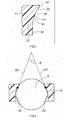
- FIG. 4 is a schematic sectional view of the cage 4 which is taken along the radial direction, and which illustrates a portion at which the tapered roller 3 is located in the pocket 25 of the cage 4 when the tapered roller 3 is present at an upper side in a vertical direction as shown in A in FIG. 2 .
- black circle marks shown in FIG. 4 indicate positions on the roller guide surfaces 40, at which the tapered roller 3 contacts the roller guide surfaces 40.
- an extension line 60 extending outward in the radial direction from one of the first portions 50 that are opposed to each other across the pocket 25 in the circumferential direction
- an extension 61 extending outward in the radial direction from the other of the first portions 50 cross each other so as to form a vertex angle (indicated by ⁇ in FIG. 4 ) that is equal to or larger than 35 degrees, and equal to or smaller than 55 degrees.
- the cage 4 is moved downward by the weight of the cage 4, and accordingly, the tapered roller 3 is moved upward relative to the cage 4.
- the tapered roller 3 is held between the two first portions 50 that are opposed to each other across the pocket 25.
- the tapered roller 3 cannot move outward in the radial direction from the pocket 25, and accordingly, it is possible to prevent the tapered roller 3 from coming off the pocket 25.
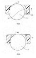
- FIG. 5 is a schematic sectional view of the cage 4 which is taken along the radial direction, and which illustrates a portion at which the tapered roller 3 is located in the pocket 25 of the cage 4 when the tapered roller 3 is present around an intermediate position between the upper position in the vertical direction and a horizontal position (intermediate position between the upper position and a lower position in the vertical direction), as shown in B in FIG. 2 .
- a black circle mark in FIG. 5 indicates a position on the roller guide surface 40, at which the tapered roller 3 contacts the roller guide surface 40.
- the second portion 51 has a curvature radius that is equal to or larger than 1.01 times, and equal to or smaller than 1.03 times a radius of the tapered roller 3 in the section.
- the second portion 51 has the curvature radius that is equal to or larger than 1.01 times, and equal to or smaller than 1.03 times the radius of the tapered roller 3.
- the second portion 51 is smoothly connected to the inner side end portion of the first portion 50 in the radial direction. Due to this, as the position of the tapered roller 3 changes from the upper position in the vertical direction to the horizontal position, the tapered roller 3 is successively moved on the first portion 50, the second portion 51 and the third portion 52, and thus, the tapered roller 3 is moved from the first portion 50 to the third portion 52, while one-point contact between the tapered roller 3 and the bar portion 22 is maintained.
- the tapered roller 3 when the tapered roller 3 is present around the intermediate position shown in B as described above, the tapered roller 3 makes one-point contact with only the second portion 51 of one of the two bar portions 22 that are opposed to each other across the pocket 25.
- FIG. 6 is a schematic sectional view of the cage 4 which is taken along the radial direction, and which illustrates a portion at which the tapered roller 3 is located in the pocket 25 of the cage 4 when the tapered roller 3 is present around the horizontal position as shown in C in FIG. 2 . It is to be noted that a black circle mark in FIG. 6 indicates a position on the roller guide surface 40, at which the tapered roller 3 contacts the roller guide surface 40.
- a distance between one of the third portions 52 that are opposed to each other across the pocket 25 in the circumferential direction and the other of the third portions 52 is larger than a diameter of the tapered roller 3 in the section.
- the tapered roller 3 when the tapered roller 3 is present around the horizontal position indicated by C in FIG. 2 , the tapered roller 3 is advanced in the circumferential direction so as to receive a circumferential force from the cage 4. However, in this case, the tapered roller 3 makes one-point contact with only the third portion 52 of one of the two bar portions 22 that are opposed to each other across the pocket 25.
- each of the third portions 52 is substantially parallel to a straight line that passes through a center of the pocket 25 and that extends in the radial direction.
- the extension lines 60, 61 extending outward in the radial direction from the two straight first portions 50 that are opposed to each other across the pocket 25 cross each other so as to form a vertex angle that is equal to or larger than 35 degrees, and equal to or smaller than 55 degrees.
- the second portion 51 smoothly connected to the inner side end portion of the first portion 50 in the radial direction is the curve having the curvature radius that equal to or larger than 1.01 times, and equal to or smaller than 1.03 times the radius of the tapered roller 3 in each section taken along the radial direction.
- the tapered roller 3 which is moved outward in the radial direction in the pocket 25 relative to the cage 4 due to the downward movement of the cage 4 in the vertical direction caused by the weight of the cage 4, can be held between the two first portions 50 that are opposed to each other across the pocket 25.
- the tapered roller 3 it is possible to prevent the tapered roller 3 from coming off outward in the radial direction.
- the straight third portion 52 is connected to the straight first portion 50 with the smoothly curved second portion 51 being interposed between the straight first portion 50 and the straight third portion 52.
- the tapered roller 3 when the tapered roller 3 is present around the horizontal position where the advancing direction of the tapered roller 3 coincides with the vertically downward direction, the tapered roller 3 can be restrained from being brought to an innermost position in the cage 4. Thus, it is possible to stably guide the tapered rollers 3 by the cage 4.
- the straight first portion 50 is connected to the straight third portion 52 through the curved second portion 51 having the curvature radius that is slightly larger than the radius of the tapered roller 3.
- the tapered roller 3 can make one-point contact with the second portion 51, and accordingly, it is possible to prevent the tapered roller 3 from making two-point contact with the first portion 50 and third portion 52.
- the tapered roller 3 may make two-point contact with the first portion 50 and the third portion 52.
- the force of the cage 4 for restraining the tapered rollers 3 becomes larger, and accordingly, the cage 4 exerts a large braking force on the tapered rollers 3. This makes it impossible for the tapered rollers 3 to smoothly roll.
- the tapered roller 3 which contacts the cage 4, can be prevented from making contact with two or more of the three surfaces, that is, the first portion 50, the second portion 51 and the third portion 52 that serve as a guide surface.
- the tapered roller 3 can be smoothly guided by the optimum surface among the first portion 50 serving as a cage inner inclined surface, the third portion 52 serving as a roller advancing direction guide surface and the second portion 51 serving as a joint rounded surface.
- each of the third portions 52 is parallel to the straight line that passes through the center of the pocket 25 and that extends in the radial direction, in the above-described section taken along the radial direction.
- the line segment connecting the contact point, at which the tapered roller 3 contacts the third portion 52, with the center of the tapered roller 3 crosses the straight third portion 52 at an angle that is close to approximately 90 degrees. Accordingly, it is possible to substantially minimize the force for bringing the tapered roller 3 to an innermost position in the cage 4. Thus, it is possible to guide the tapered rollers 3 more stably.
- the rolling elements are the tapered rollers 3.
- the rolling elements may be cylindrical rollers, or convex rollers (spherical rollers).
- each of the third portions 52 is substantially parallel to the line that passes through the center of the pocket 25 and that extends in the radial direction, in the section of the cage 4 taken along the radial direction.
- the third portion 52 may have any shape, as long as the third portion 52 is smoothly connected to the inner side end portion of the second portion 51 in the radial direction, and has a straight line shape. When these conditions are satisfied, the tapered roller 3 can be restrained from being brought to an innermost position in the cage 4.
- the resin cage according to the present invention can be appropriately formed by injection molding, needless to say, the method of forming the resin cage according to the present invention should not be limited to this injection molding.
- each of tapered roller guide surfaces of bar portions, which face pockets includes a straight first portion; a curved second portion having a curvature radius that is equal to or larger than 1.01 times and equal to or smaller than 1.03 times a radius of a tapered roller in the section; and a straight third portion.
- extension lines of the two first portions that are opposed to each other across the pocket in the circumferential direction form a vertex angle that is equal to or larger than 35 degrees, and equal to or smaller than 55 degrees.
- a distance between the two third portions that are opposed to each other across the pocket in the circumferential direction is larger than a diameter of the tapered roller in the section.
Landscapes
- Engineering & Computer Science (AREA)
- General Engineering & Computer Science (AREA)
- Mechanical Engineering (AREA)
- Rolling Contact Bearings (AREA)
Abstract

Description
- The present invention relates to a resin cage and a roller bearing.
- Conventionally, as an example of a roller bearing, there is a tapered roller bearing described in Japanese Patent Application Publication No.
2010-091007 - There are pockets in which tapered rollers are respectively arranged, and each of the pockets is defined between the bar portions that are adjacent to each other in the circumferential direction. The bar portions have roller guide surfaces that face the pockets, and some of the roller guide surfaces have inclined surface portions that are formed so that a distance between the opposed inclined surface portions gradually increases toward an inner side in a radial direction. In the above-described conventional tapered roller bearing, the tapered rollers are stably guided by the above-described inclined surface portions of the cage.
- However, in the above-described conventional tapered roller bearing, since the cage is made of a metal, an impact load caused by the weight of the cage may become large due to the large mass of the cage, and as a result, the cage may be broken.
- The inventor of the present invention has found that the following problem is caused in a case where a resin cage is used in order to settle the problem that the metal cage may be broken due to the weight of the metal cage.
- Namely, the inventor has found that, in a case where inclined surface portions are formed on bar portions of the resin cage so that a distance between the opposed inclined surface portions increases toward an inner side in a radial direction, and rollers are guided only by the inclined surface portions, as in the metal cage, each of the rollers is brought to an innermost position in the cage due to elasticity of the resin cage when the roller is present around a position at which an advancing direction of the roller coincides with a vertically downward direction. Thus, the rollers cannot be stably retained.
- An object of the present invention is to provide a resin cage in which rollers are restrained from being brought to an innermost position, and thus the rollers are stably guided.
- According to the present invention, there is provided a resin cage including: a first annular portion; a second annular portion opposed to the first annular portion in an axial direction of the first annular portion; and a plurality of bar portions spaced from each other in a circumferential direction of the first annular portion, and connecting the first annular portion with the second annular portion, wherein the resin cage has pockets each of which is defined between the bar portions adjacent to each other in the circumferential direction, and the rollers are respectively disposed in the pockets, wherein in a section which is taken along a radial direction, and which passes through only the bar portions in a state in which the rollers are respectively accommodated in the pockets, the bar portions have roller guide surfaces facing the pockets, and each of the roller guide surfaces includes: a straight first portion; a curved second portion smoothly connected to an inner side end portion of the first portion in the radial direction, the second portion having a curvature radius that is equal to or larger than 1.01 times, and equal to or smaller than 1.03 times a radius of the roller in the section, and the second portion protruding toward a side opposite to the pocket in the circumferential direction; and a straight third portion smoothly connected to an inner side end portion of the second portion in the radial direction, wherein in the section, an extension line extending outward in the radial direction from one of the first portions that are opposed to each other across the pocket in the circumferential direction, and an extension line extending outward in the radial direction from the other of the first portions cross each other so as to form a vertex angle that is equal to or larger than 35 degrees, and equal to or smaller than 55 degrees, and wherein in the section, a distance between one of the third portions that are opposed to each other across the pocket in the circumferential direction and the other of the third portions is larger than a diameter of the roller in the section.
- The foregoing and further features and advantages of the invention will become apparent from the following example embodiments with reference to the accompanying drawings, wherein like numerals represent like elements, and wherein:
-
FIG. 1 is a sectional view of a tapered roller bearing as an embodiment of a roller bearing according to the present invention, the sectional view being taken along an axial direction; -
FIG. 2 is a perspective view illustrating an inner ring, tapered rollers and a cage in a state in which the tapered roller bearing supports a horizontal shaft that extends horizontally (not shown); -
FIG. 3 is a schematic sectional view of the cage which is taken along a radial direction, and which passes through only a bar portion and illustrates a shape of a roller guide surface of the bar portion, the roller guide surface facing a pocket; -
FIG. 4 is a schematic sectional view of the cage which is taken along the radial direction, and which illustrates a portion at which a tapered roller is located in the pocket of the cage when the tapered roller is present at an upper position in a vertical direction as shown in A inFIG. 2 ; -
FIG. 5 is a schematic sectional view of the cage which is taken along the radial direction, and which illustrates a portion at which the tapered roller is located in the pocket of the cage when the tapered roller is present around an intermediate position between the upper position in the vertical direction and a horizontal position (an intermediate position between the upper position and the lower position in the vertical direction) as shown in B inFIG. 2 ; and -
FIG. 6 is a schematic sectional view of the cage which is taken along the radial direction, and which illustrates a portion at which the tapered roller is located in the pocket of the cage when the tapered roller is present around the horizontal position as shown in C inFIG. 2 . - Hereinafter, the present invention will be described in detail with reference to an embodiment illustrated in the accompanying drawings.
-
FIG. 1 is a sectional view of a tapered roller bearing as an embodiment of a roller bearing according to the present invention, the sectional view being taken along an axial direction. - As shown in
FIG. 1 , the tapered roller bearing includes anouter ring 1, aninner ring 2, a plurality oftapered rollers 3 and aresin cage 4. Theouter ring 1 has an inner peripheraltapered raceway surface 5. On the other hand, theinner ring 2 has an outer peripheraltapered raceway surface 7. Theinner ring 2 has a smallrib face 10 at a small diameter-side end of the outer peripheraltapered raceway surface 7, and has a largerib face 11 at a large diameter-side end of the outer peripheraltapered raceway surface 7. - The
tapered rollers 3 are spaced from each other in a circumferential direction in a state in which the tapered rollers are retained by thecage 4 between the inner peripheraltapered raceway surface 5 of theouter ring 1 and the outer peripheraltapered raceway surface 7 of theinner ring 2. The largerib face 11 of theinner ring 2 guides large diameter end faces 15 of thetapered rollers 3 during operation of the tapered roller bearing. -
FIG. 2 is a perspective view illustrating theinner ring 2, thetapered rollers 3 and thecage 4 in a state in which the tapered roller bearing supports a horizontal shaft that extends horizontally (not shown). - As shown in
FIG. 2 , thecage 4 has a small diameterannular portion 20 as a first annular portion, a large diameterannular portion 21 as a second annular portion, and a plurality ofbar portions 22. Thebar portions 22 are spaced from each other in a circumferential direction of the small diameterannular portion 20. Thebar portions 22 connect the small diameterannular portion 20 with the large diameterannular portion 21. As shown inFIG. 2 , thecage 4 haspockets 25 each of which is defined between thebar portions 22 that are adjacent to each other in the circumferential direction, and thetapered rollers 3 are disposed respectively in thepockets 25. -
FIG. 3 is a schematic sectional view of thecage 4 which is taken along a radial direction, and which passes through only thebar portion 22 and illustrates a shape of aroller guide surface 40 of thebar portion 22, theroller guide surface 40 facing thepocket 25. - As shown in
FIG. 3 , in thiscage 4, theroller guide surface 40 of each of thebar portions 22 has a straightfirst portion 50, a curvedsecond portion 51 and a straightthird portion 52, in the section of thecage 4 which is taken along the radial direction, and which passes through only thebar portion 22. - In the section taken along the radial direction, the
second portion 51 is smoothly (i.e., in a differentiable manner) connected to an inner side end portion of thefirst portion 50 in the radial direction. Thesecond portion 51 is composed of a curve that protrudes toward a side opposite to thepocket 25 in the circumferential direction, in the section. Further, in the section, thethird portion 52 is smoothly (i.e., in a differentiable manner) connected to an inner side end portion of thesecond portion 51 in the radial direction. -
FIG. 4 is a schematic sectional view of thecage 4 which is taken along the radial direction, and which illustrates a portion at which thetapered roller 3 is located in thepocket 25 of thecage 4 when thetapered roller 3 is present at an upper side in a vertical direction as shown in A inFIG. 2 . It is to be noted that black circle marks shown inFIG. 4 indicate positions on theroller guide surfaces 40, at which thetapered roller 3 contacts theroller guide surfaces 40. - As shown in
FIG. 4 , in the section of thecage 4 taken along the radial direction, anextension line 60 extending outward in the radial direction from one of thefirst portions 50 that are opposed to each other across thepocket 25 in the circumferential direction, and anextension 61 extending outward in the radial direction from the other of thefirst portions 50 cross each other so as to form a vertex angle (indicated by θ inFIG. 4 ) that is equal to or larger than 35 degrees, and equal to or smaller than 55 degrees. - At the position at which the
tapered roller 3 is present at the upper side in the vertical direction as shown in A inFIG. 2 , thecage 4 is moved downward by the weight of thecage 4, and accordingly, thetapered roller 3 is moved upward relative to thecage 4. At this position, as shown inFIG. 4 , thetapered roller 3 is held between the twofirst portions 50 that are opposed to each other across thepocket 25. Thus, thetapered roller 3 cannot move outward in the radial direction from thepocket 25, and accordingly, it is possible to prevent thetapered roller 3 from coming off thepocket 25. -
FIG. 5 is a schematic sectional view of thecage 4 which is taken along the radial direction, and which illustrates a portion at which thetapered roller 3 is located in thepocket 25 of thecage 4 when thetapered roller 3 is present around an intermediate position between the upper position in the vertical direction and a horizontal position (intermediate position between the upper position and a lower position in the vertical direction), as shown in B inFIG. 2 . It is to be noted that a black circle mark inFIG. 5 indicates a position on theroller guide surface 40, at which thetapered roller 3 contacts theroller guide surface 40. - In the section which is taken along the radial direction, and which passes through only the
bar portion 22 in a state in which thetapered roller 3 is accommodated in thepocket 25, thesecond portion 51 has a curvature radius that is equal to or larger than 1.01 times, and equal to or smaller than 1.03 times a radius of thetapered roller 3 in the section. - As described above, in the section, the
second portion 51 has the curvature radius that is equal to or larger than 1.01 times, and equal to or smaller than 1.03 times the radius of thetapered roller 3. In addition, thesecond portion 51 is smoothly connected to the inner side end portion of thefirst portion 50 in the radial direction. Due to this, as the position of thetapered roller 3 changes from the upper position in the vertical direction to the horizontal position, thetapered roller 3 is successively moved on thefirst portion 50, thesecond portion 51 and thethird portion 52, and thus, thetapered roller 3 is moved from thefirst portion 50 to thethird portion 52, while one-point contact between thetapered roller 3 and thebar portion 22 is maintained. - Further, as shown in
FIG. 5 , when thetapered roller 3 is present around the intermediate position shown in B as described above, thetapered roller 3 makes one-point contact with only thesecond portion 51 of one of the twobar portions 22 that are opposed to each other across thepocket 25. -
FIG. 6 is a schematic sectional view of thecage 4 which is taken along the radial direction, and which illustrates a portion at which thetapered roller 3 is located in thepocket 25 of thecage 4 when thetapered roller 3 is present around the horizontal position as shown in C inFIG. 2 . It is to be noted that a black circle mark inFIG. 6 indicates a position on theroller guide surface 40, at which thetapered roller 3 contacts theroller guide surface 40. - In the section which is taken along the radial direction, and which passes through only the
bar portions 22 in the state in which thetapered roller 3 is accommodated in thepocket 25, a distance between one of thethird portions 52 that are opposed to each other across thepocket 25 in the circumferential direction and the other of thethird portions 52 is larger than a diameter of thetapered roller 3 in the section. - Further, when the
tapered roller 3 is present around the horizontal position indicated by C inFIG. 2 , thetapered roller 3 is advanced in the circumferential direction so as to receive a circumferential force from thecage 4. However, in this case, thetapered roller 3 makes one-point contact with only thethird portion 52 of one of the twobar portions 22 that are opposed to each other across thepocket 25. - Further, in the section of the
cage 4 taken along the radial direction shown inFIG. 6 , each of thethird portions 52 is substantially parallel to a straight line that passes through a center of thepocket 25 and that extends in the radial direction. - According to the above-described embodiment, in the section of the
cage 4 which is taken along the radial direction, the extension lines 60, 61 extending outward in the radial direction from the two straightfirst portions 50 that are opposed to each other across thepocket 25 cross each other so as to form a vertex angle that is equal to or larger than 35 degrees, and equal to or smaller than 55 degrees. Further, thesecond portion 51 smoothly connected to the inner side end portion of thefirst portion 50 in the radial direction is the curve having the curvature radius that equal to or larger than 1.01 times, and equal to or smaller than 1.03 times the radius of the taperedroller 3 in each section taken along the radial direction. In view of the foregoing, the taperedroller 3, which is moved outward in the radial direction in thepocket 25 relative to thecage 4 due to the downward movement of thecage 4 in the vertical direction caused by the weight of thecage 4, can be held between the twofirst portions 50 that are opposed to each other across thepocket 25. Thus, it is possible to prevent the taperedroller 3 from coming off outward in the radial direction. - Further, according to the above-described embodiment, in the section taken along the radial direction, the straight
third portion 52 is connected to the straightfirst portion 50 with the smoothly curvedsecond portion 51 being interposed between the straightfirst portion 50 and the straightthird portion 52. Thus, when the taperedroller 3 is present around the horizontal position where the advancing direction of the taperedroller 3 coincides with the vertically downward direction, and the taperedroller 3 contacts thethird portion 52, a line segment connecting a contact point, at which the taperedroller 3 contacts thethird portion 52, with the center of the taperedroller 3 crosses the straightthird portion 52 at an angle that is close to 90 degrees in the section taken along the radial direction. Thus, when the taperedroller 3 is present around the horizontal position where the advancing direction of the taperedroller 3 coincides with the vertically downward direction, the taperedroller 3 can be restrained from being brought to an innermost position in thecage 4. Thus, it is possible to stably guide the taperedrollers 3 by thecage 4. - Further, according to the above-described embodiment, the straight
first portion 50 is connected to the straightthird portion 52 through the curvedsecond portion 51 having the curvature radius that is slightly larger than the radius of the taperedroller 3. Thus, during the process in which the contact point of the taperedroller 3 is shifted from thefirst portion 50 to thethird portion 52, the taperedroller 3 can make one-point contact with thesecond portion 51, and accordingly, it is possible to prevent the taperedroller 3 from making two-point contact with thefirst portion 50 andthird portion 52. Thus, it is possible to ensure that the taperedrollers 3 smoothly roll, and accordingly, it is possible to obtain higher bearing load-carrying capacity. - If the straight
first portion 50 is directly connected to the straightthird portion 52 so as to form a polygonal line, without interposing thesecond portion 51 between the straightfirst portion 50 and the straightthird portion 52, the taperedroller 3 may make two-point contact with thefirst portion 50 and thethird portion 52. In this case, the force of thecage 4 for restraining the taperedrollers 3 becomes larger, and accordingly, thecage 4 exerts a large braking force on the taperedrollers 3. This makes it impossible for the taperedrollers 3 to smoothly roll. - Namely, regardless of the circumferential position at which the tapered
roller 3 is located, the taperedroller 3, which contacts thecage 4, can be prevented from making contact with two or more of the three surfaces, that is, thefirst portion 50, thesecond portion 51 and thethird portion 52 that serve as a guide surface. Thus, the taperedroller 3 can be smoothly guided by the optimum surface among thefirst portion 50 serving as a cage inner inclined surface, thethird portion 52 serving as a roller advancing direction guide surface and thesecond portion 51 serving as a joint rounded surface. - Further, according to the above-described embodiment, each of the
third portions 52 is parallel to the straight line that passes through the center of thepocket 25 and that extends in the radial direction, in the above-described section taken along the radial direction. Thus, in the above-described section, the line segment connecting the contact point, at which the taperedroller 3 contacts thethird portion 52, with the center of the taperedroller 3 crosses the straightthird portion 52 at an angle that is close to approximately 90 degrees. Accordingly, it is possible to substantially minimize the force for bringing the taperedroller 3 to an innermost position in thecage 4. Thus, it is possible to guide the taperedrollers 3 more stably. - In the above-described embodiment, the rolling elements are the tapered
rollers 3. However, in the present application, the rolling elements may be cylindrical rollers, or convex rollers (spherical rollers). - Further, in the above-described embodiment, each of the
third portions 52 is substantially parallel to the line that passes through the center of thepocket 25 and that extends in the radial direction, in the section of thecage 4 taken along the radial direction. However, in the present invention, thethird portion 52 may have any shape, as long as thethird portion 52 is smoothly connected to the inner side end portion of thesecond portion 51 in the radial direction, and has a straight line shape. When these conditions are satisfied, the taperedroller 3 can be restrained from being brought to an innermost position in thecage 4. - It is to be noted that the cage according to the present invention is appropriately used in a roller bearing which supports an axle of a railway vehicle, and in which a metal cage is currently used in general, and the cage oscillates due to frequent vibrations. In addition, it goes without saying that the roller bearing in which the cage according to the present invention is used is not limited to the above-described roller bearing, and the cage according to the present invention may be used in roller bearings for any purposes, such as a roller bearing that supports a main shaft of a wind power generator and a roller bearing that supports a pinion shaft of a differential gear.
- Further, although the resin cage according to the present invention can be appropriately formed by injection molding, needless to say, the method of forming the resin cage according to the present invention should not be limited to this injection molding.
- According to the present invention, it is possible to realize the resin cage in which the rollers are restrained from being brought to the innermost position in the cage, and the rollers are stably guided.
In a section of a cage taken along a radial direction, each of tapered roller guide surfaces of bar portions, which face pockets, includes a straight first portion; a curved second portion having a curvature radius that is equal to or larger than 1.01 times and equal to or smaller than 1.03 times a radius of a tapered roller in the section; and a straight third portion. In the section, extension lines of the two first portions that are opposed to each other across the pocket in the circumferential direction form a vertex angle that is equal to or larger than 35 degrees, and equal to or smaller than 55 degrees. In the section, a distance between the two third portions that are opposed to each other across the pocket in the circumferential direction is larger than a diameter of the tapered roller in the section.
Claims (3)
- A resin cage comprising:a first annular portion;a second annular portion opposed to the first annular portion in an axial direction of the first annular portion; anda plurality of bar portions spaced from each other in a circumferential direction of the first annular portion, and connecting the first annular portion with the second annular portion,wherein the resin cage has pockets each of which is defined between the bar portions adjacent to each other in the circumferential direction, and the rollers are respectively disposed in the pockets,wherein in a section which is taken along a radial direction, and which passes through only the bar portions in a state in which the rollers are respectively accommodated in the pockets, the bar portions have roller guide surfaces facing the pockets, and each of the roller guide surfaces includes:a straight first portion;a curved second portion smoothly connected to an inner side end portion of the first portion in the radial direction, the second portion having a curvature radius that is equal to or larger than 1.01 times, and equal to or smaller than 1.03 times a radius of the roller in the section, and the second portion protruding toward a side opposite to the pocket in the circumferential direction; anda straight third portion smoothly connected to an inner side end portion of the second portion in the radial direction,wherein in the section, an extension line extending outward in the radial direction from one of the first portions that are opposed to each other across the pocket in the circumferential direction, and an extension line extending outward in the radial direction from the other of the first portions cross each other so as to form a vertex angle that is equal to or larger than 35 degrees, and equal to or smaller than 55 degrees, andwherein in the section, a distance between one of the third portions that are opposed to each other across the pocket in the circumferential direction and the other of the third portions is larger than a diameter of the roller in the section.
- The resin cage according to claim 1, wherein in the section, each of the third portions is substantially parallel to a straight line that passes through a center of the pocket, and that extends in the radial direction.
- A roller bearing comprising:an outer ring having a raceway surface;an inner ring having a raceway surface;a plurality of rollers disposed between the raceway surface of the outer ring and the raceway surface of the inner ring; andthe resin cage according to claim 1 or 2, the resin cage retaining the rollers.
Applications Claiming Priority (1)
| Application Number | Priority Date | Filing Date | Title |
|---|---|---|---|
| JP2012199677A JP6069985B2 (en) | 2012-09-11 | 2012-09-11 | Resin cage and roller bearing |
Publications (3)
| Publication Number | Publication Date |
|---|---|
| EP2706249A2 true EP2706249A2 (en) | 2014-03-12 |
| EP2706249A3 EP2706249A3 (en) | 2014-11-19 |
| EP2706249B1 EP2706249B1 (en) | 2016-05-04 |
Family
ID=49117732
Family Applications (1)
| Application Number | Title | Priority Date | Filing Date |
|---|---|---|---|
| EP13183294.1A Not-in-force EP2706249B1 (en) | 2012-09-11 | 2013-09-06 | Resin cage and roller bearing |
Country Status (3)
| Country | Link |
|---|---|
| EP (1) | EP2706249B1 (en) |
| JP (1) | JP6069985B2 (en) |
| CN (1) | CN103671552B (en) |
Families Citing this family (4)
| Publication number | Priority date | Publication date | Assignee | Title |
|---|---|---|---|---|
| JP2018080719A (en) * | 2016-11-14 | 2018-05-24 | 日本精工株式会社 | Resin-made cage for cylindrical roller bearing and cylindrical roller bearing |
| WO2019172448A1 (en) * | 2018-03-09 | 2019-09-12 | 日本精工株式会社 | Tapered roller bearing |
| JP2021092229A (en) * | 2019-12-06 | 2021-06-17 | 株式会社ジェイテクト | Holder for radial roller bearing |
| CN115289133A (en) * | 2022-08-25 | 2022-11-04 | 瓦房店轴承集团有限责任公司 | Step type external diameter self-sealing double-row tapered roller bearing |
Citations (1)
| Publication number | Priority date | Publication date | Assignee | Title |
|---|---|---|---|---|
| JP2010091007A (en) | 2008-10-08 | 2010-04-22 | Ntn Corp | Retainer for conical roller bearing, and conical roller bearing |
Family Cites Families (10)
| Publication number | Priority date | Publication date | Assignee | Title |
|---|---|---|---|---|
| JPS49101133U (en) * | 1972-12-21 | 1974-08-30 | ||
| US4288129A (en) * | 1980-04-11 | 1981-09-08 | Federal-Mogul Corporation | Bearing cage |
| DE9111111U1 (en) * | 1991-09-07 | 1991-11-07 | SKF GmbH, 8720 Schweinfurt | Roller guided cage for bearings |
| JP3699249B2 (en) * | 1997-07-28 | 2005-09-28 | Ntn株式会社 | Hub unit bearing and manufacturing method thereof |
| JP3733747B2 (en) * | 1997-10-01 | 2006-01-11 | 日本精工株式会社 | Synthetic resin cage and roller bearing for roller bearings |
| JP2005069282A (en) * | 2003-08-20 | 2005-03-17 | Ntn Corp | Cylindrical roller bearing |
| EP1757823B2 (en) * | 2005-08-25 | 2015-01-07 | NTN Corporation | Tapered roller bearing |
| JP4573791B2 (en) * | 2006-03-29 | 2010-11-04 | Ntn株式会社 | Roller bearing and main shaft support structure of wind power generator |
| US8591121B2 (en) * | 2009-04-06 | 2013-11-26 | Jtekt Corporation | Rolling bearing cage and assembly |
| JP5531551B2 (en) * | 2009-10-22 | 2014-06-25 | 株式会社ジェイテクト | Roller bearing cage, inner ring assembly, outer ring assembly and rolling bearing provided with the cage |
-
2012
- 2012-09-11 JP JP2012199677A patent/JP6069985B2/en active Active
-
2013
- 2013-08-26 CN CN201310376265.7A patent/CN103671552B/en not_active Expired - Fee Related
- 2013-09-06 EP EP13183294.1A patent/EP2706249B1/en not_active Not-in-force
Patent Citations (1)
| Publication number | Priority date | Publication date | Assignee | Title |
|---|---|---|---|---|
| JP2010091007A (en) | 2008-10-08 | 2010-04-22 | Ntn Corp | Retainer for conical roller bearing, and conical roller bearing |
Also Published As
| Publication number | Publication date |
|---|---|
| CN103671552B (en) | 2017-08-25 |
| JP6069985B2 (en) | 2017-02-01 |
| CN103671552A (en) | 2014-03-26 |
| EP2706249A3 (en) | 2014-11-19 |
| JP2014055612A (en) | 2014-03-27 |
| EP2706249B1 (en) | 2016-05-04 |
Similar Documents
| Publication | Publication Date | Title |
|---|---|---|
| EP3543553B1 (en) | Rolling bearing cage and rolling bearing | |
| US9541126B2 (en) | Large rolling bearing | |
| US9188160B2 (en) | Configuration for a roller of a roller bearing | |
| US10208796B2 (en) | Segmented cage for a bearing | |
| EP2706249B1 (en) | Resin cage and roller bearing | |
| US20200408260A1 (en) | Inner ring unit and tapered roller bearing | |
| US20140254971A1 (en) | Rolling bearing | |
| EP2730793A2 (en) | Cage for thrust roller bearing | |
| US20200158167A1 (en) | Tapered roller bearing | |
| US9797440B2 (en) | Bearing | |
| US9829038B2 (en) | Bearing and bearing arrangement | |
| US20080310788A1 (en) | Rolling Bearing with Improved Rim Geometry | |
| JP2006242284A (en) | Cylindrical roller bearing with flange | |
| JP2010019284A (en) | Retainer for conical roller bearing, and conical roller bearing | |
| US9121443B2 (en) | Angular ball bearing | |
| US20160032974A1 (en) | Tapered roller bearing | |
| JP5532157B2 (en) | Tapered roller bearing cage and tapered roller bearing | |
| JP2007198464A (en) | Cylindrical roller bearing with aligning ring | |
| JP2016075376A (en) | Spherical roller bearing | |
| KR20190058635A (en) | Resin retainers and cylindrical roller bearings for cylindrical roller bearings | |
| US20180335085A1 (en) | Ball bearing cage | |
| US9732793B2 (en) | Bearing and bearing arrangement | |
| JP2013185694A (en) | Rolling bearing with aligning ring | |
| JP2020079646A (en) | Spherical roller bearing | |
| JP2011127680A (en) | Thrust roller bearing |
Legal Events
| Date | Code | Title | Description |
|---|---|---|---|
| PUAI | Public reference made under article 153(3) epc to a published international application that has entered the european phase |
Free format text: ORIGINAL CODE: 0009012 |
|
| AK | Designated contracting states |
Kind code of ref document: A2 Designated state(s): AL AT BE BG CH CY CZ DE DK EE ES FI FR GB GR HR HU IE IS IT LI LT LU LV MC MK MT NL NO PL PT RO RS SE SI SK SM TR |
|
| AX | Request for extension of the european patent |
Extension state: BA ME |
|
| PUAL | Search report despatched |
Free format text: ORIGINAL CODE: 0009013 |
|
| AK | Designated contracting states |
Kind code of ref document: A3 Designated state(s): AL AT BE BG CH CY CZ DE DK EE ES FI FR GB GR HR HU IE IS IT LI LT LU LV MC MK MT NL NO PL PT RO RS SE SI SK SM TR |
|
| AX | Request for extension of the european patent |
Extension state: BA ME |
|
| RIC1 | Information provided on ipc code assigned before grant |
Ipc: F16C 33/46 20060101AFI20141010BHEP Ipc: F16C 19/36 20060101ALI20141010BHEP |
|
| 17P | Request for examination filed |
Effective date: 20141217 |
|
| GRAP | Despatch of communication of intention to grant a patent |
Free format text: ORIGINAL CODE: EPIDOSNIGR1 |
|
| INTG | Intention to grant announced |
Effective date: 20160119 |
|
| GRAS | Grant fee paid |
Free format text: ORIGINAL CODE: EPIDOSNIGR3 |
|
| GRAA | (expected) grant |
Free format text: ORIGINAL CODE: 0009210 |
|
| AK | Designated contracting states |
Kind code of ref document: B1 Designated state(s): AL AT BE BG CH CY CZ DE DK EE ES FI FR GB GR HR HU IE IS IT LI LT LU LV MC MK MT NL NO PL PT RO RS SE SI SK SM TR |
|
| REG | Reference to a national code |
Ref country code: GB Ref legal event code: FG4D |
|
| REG | Reference to a national code |
Ref country code: CH Ref legal event code: EP |
|
| REG | Reference to a national code |
Ref country code: AT Ref legal event code: REF Ref document number: 797188 Country of ref document: AT Kind code of ref document: T Effective date: 20160515 |
|
| REG | Reference to a national code |
Ref country code: IE Ref legal event code: FG4D |
|
| REG | Reference to a national code |
Ref country code: DE Ref legal event code: R096 Ref document number: 602013007222 Country of ref document: DE |
|
| REG | Reference to a national code |
Ref country code: NL Ref legal event code: MP Effective date: 20160504 |
|
| REG | Reference to a national code |
Ref country code: LT Ref legal event code: MG4D |
|
| PG25 | Lapsed in a contracting state [announced via postgrant information from national office to epo] |
Ref country code: FI Free format text: LAPSE BECAUSE OF FAILURE TO SUBMIT A TRANSLATION OF THE DESCRIPTION OR TO PAY THE FEE WITHIN THE PRESCRIBED TIME-LIMIT Effective date: 20160504 Ref country code: LT Free format text: LAPSE BECAUSE OF FAILURE TO SUBMIT A TRANSLATION OF THE DESCRIPTION OR TO PAY THE FEE WITHIN THE PRESCRIBED TIME-LIMIT Effective date: 20160504 Ref country code: NO Free format text: LAPSE BECAUSE OF FAILURE TO SUBMIT A TRANSLATION OF THE DESCRIPTION OR TO PAY THE FEE WITHIN THE PRESCRIBED TIME-LIMIT Effective date: 20160804 Ref country code: NL Free format text: LAPSE BECAUSE OF FAILURE TO SUBMIT A TRANSLATION OF THE DESCRIPTION OR TO PAY THE FEE WITHIN THE PRESCRIBED TIME-LIMIT Effective date: 20160504 |
|
| REG | Reference to a national code |
Ref country code: AT Ref legal event code: MK05 Ref document number: 797188 Country of ref document: AT Kind code of ref document: T Effective date: 20160504 |
|
| PG25 | Lapsed in a contracting state [announced via postgrant information from national office to epo] |
Ref country code: HR Free format text: LAPSE BECAUSE OF FAILURE TO SUBMIT A TRANSLATION OF THE DESCRIPTION OR TO PAY THE FEE WITHIN THE PRESCRIBED TIME-LIMIT Effective date: 20160504 Ref country code: ES Free format text: LAPSE BECAUSE OF FAILURE TO SUBMIT A TRANSLATION OF THE DESCRIPTION OR TO PAY THE FEE WITHIN THE PRESCRIBED TIME-LIMIT Effective date: 20160504 Ref country code: LV Free format text: LAPSE BECAUSE OF FAILURE TO SUBMIT A TRANSLATION OF THE DESCRIPTION OR TO PAY THE FEE WITHIN THE PRESCRIBED TIME-LIMIT Effective date: 20160504 Ref country code: SE Free format text: LAPSE BECAUSE OF FAILURE TO SUBMIT A TRANSLATION OF THE DESCRIPTION OR TO PAY THE FEE WITHIN THE PRESCRIBED TIME-LIMIT Effective date: 20160504 Ref country code: PT Free format text: LAPSE BECAUSE OF FAILURE TO SUBMIT A TRANSLATION OF THE DESCRIPTION OR TO PAY THE FEE WITHIN THE PRESCRIBED TIME-LIMIT Effective date: 20160905 Ref country code: RS Free format text: LAPSE BECAUSE OF FAILURE TO SUBMIT A TRANSLATION OF THE DESCRIPTION OR TO PAY THE FEE WITHIN THE PRESCRIBED TIME-LIMIT Effective date: 20160504 Ref country code: GR Free format text: LAPSE BECAUSE OF FAILURE TO SUBMIT A TRANSLATION OF THE DESCRIPTION OR TO PAY THE FEE WITHIN THE PRESCRIBED TIME-LIMIT Effective date: 20160805 |
|
| PG25 | Lapsed in a contracting state [announced via postgrant information from national office to epo] |
Ref country code: IT Free format text: LAPSE BECAUSE OF FAILURE TO SUBMIT A TRANSLATION OF THE DESCRIPTION OR TO PAY THE FEE WITHIN THE PRESCRIBED TIME-LIMIT Effective date: 20160504 |
|
| PG25 | Lapsed in a contracting state [announced via postgrant information from national office to epo] |
Ref country code: CZ Free format text: LAPSE BECAUSE OF FAILURE TO SUBMIT A TRANSLATION OF THE DESCRIPTION OR TO PAY THE FEE WITHIN THE PRESCRIBED TIME-LIMIT Effective date: 20160504 Ref country code: SK Free format text: LAPSE BECAUSE OF FAILURE TO SUBMIT A TRANSLATION OF THE DESCRIPTION OR TO PAY THE FEE WITHIN THE PRESCRIBED TIME-LIMIT Effective date: 20160504 Ref country code: EE Free format text: LAPSE BECAUSE OF FAILURE TO SUBMIT A TRANSLATION OF THE DESCRIPTION OR TO PAY THE FEE WITHIN THE PRESCRIBED TIME-LIMIT Effective date: 20160504 Ref country code: DK Free format text: LAPSE BECAUSE OF FAILURE TO SUBMIT A TRANSLATION OF THE DESCRIPTION OR TO PAY THE FEE WITHIN THE PRESCRIBED TIME-LIMIT Effective date: 20160504 Ref country code: RO Free format text: LAPSE BECAUSE OF FAILURE TO SUBMIT A TRANSLATION OF THE DESCRIPTION OR TO PAY THE FEE WITHIN THE PRESCRIBED TIME-LIMIT Effective date: 20160504 |
|
| REG | Reference to a national code |
Ref country code: DE Ref legal event code: R097 Ref document number: 602013007222 Country of ref document: DE |
|
| PG25 | Lapsed in a contracting state [announced via postgrant information from national office to epo] |
Ref country code: BE Free format text: LAPSE BECAUSE OF NON-PAYMENT OF DUE FEES Effective date: 20160504 Ref country code: AT Free format text: LAPSE BECAUSE OF FAILURE TO SUBMIT A TRANSLATION OF THE DESCRIPTION OR TO PAY THE FEE WITHIN THE PRESCRIBED TIME-LIMIT Effective date: 20160504 Ref country code: SM Free format text: LAPSE BECAUSE OF FAILURE TO SUBMIT A TRANSLATION OF THE DESCRIPTION OR TO PAY THE FEE WITHIN THE PRESCRIBED TIME-LIMIT Effective date: 20160504 Ref country code: PL Free format text: LAPSE BECAUSE OF FAILURE TO SUBMIT A TRANSLATION OF THE DESCRIPTION OR TO PAY THE FEE WITHIN THE PRESCRIBED TIME-LIMIT Effective date: 20160504 |
|
| PLBE | No opposition filed within time limit |
Free format text: ORIGINAL CODE: 0009261 |
|
| STAA | Information on the status of an ep patent application or granted ep patent |
Free format text: STATUS: NO OPPOSITION FILED WITHIN TIME LIMIT |
|
| 26N | No opposition filed |
Effective date: 20170207 |
|
| PG25 | Lapsed in a contracting state [announced via postgrant information from national office to epo] |
Ref country code: MC Free format text: LAPSE BECAUSE OF FAILURE TO SUBMIT A TRANSLATION OF THE DESCRIPTION OR TO PAY THE FEE WITHIN THE PRESCRIBED TIME-LIMIT Effective date: 20160504 |
|
| REG | Reference to a national code |
Ref country code: CH Ref legal event code: PL |
|
| PG25 | Lapsed in a contracting state [announced via postgrant information from national office to epo] |
Ref country code: SI Free format text: LAPSE BECAUSE OF FAILURE TO SUBMIT A TRANSLATION OF THE DESCRIPTION OR TO PAY THE FEE WITHIN THE PRESCRIBED TIME-LIMIT Effective date: 20160504 |
|
| REG | Reference to a national code |
Ref country code: IE Ref legal event code: MM4A |
|
| REG | Reference to a national code |
Ref country code: FR Ref legal event code: ST Effective date: 20170531 |
|
| PG25 | Lapsed in a contracting state [announced via postgrant information from national office to epo] |
Ref country code: CH Free format text: LAPSE BECAUSE OF NON-PAYMENT OF DUE FEES Effective date: 20160930 Ref country code: IE Free format text: LAPSE BECAUSE OF NON-PAYMENT OF DUE FEES Effective date: 20160906 Ref country code: FR Free format text: LAPSE BECAUSE OF NON-PAYMENT OF DUE FEES Effective date: 20160930 Ref country code: LI Free format text: LAPSE BECAUSE OF NON-PAYMENT OF DUE FEES Effective date: 20160930 |
|
| PG25 | Lapsed in a contracting state [announced via postgrant information from national office to epo] |
Ref country code: LU Free format text: LAPSE BECAUSE OF NON-PAYMENT OF DUE FEES Effective date: 20160906 |
|
| GBPC | Gb: european patent ceased through non-payment of renewal fee |
Effective date: 20170906 |
|
| PG25 | Lapsed in a contracting state [announced via postgrant information from national office to epo] |
Ref country code: CY Free format text: LAPSE BECAUSE OF FAILURE TO SUBMIT A TRANSLATION OF THE DESCRIPTION OR TO PAY THE FEE WITHIN THE PRESCRIBED TIME-LIMIT Effective date: 20160504 Ref country code: HU Free format text: LAPSE BECAUSE OF FAILURE TO SUBMIT A TRANSLATION OF THE DESCRIPTION OR TO PAY THE FEE WITHIN THE PRESCRIBED TIME-LIMIT; INVALID AB INITIO Effective date: 20130906 |
|
| PG25 | Lapsed in a contracting state [announced via postgrant information from national office to epo] |
Ref country code: MT Free format text: LAPSE BECAUSE OF NON-PAYMENT OF DUE FEES Effective date: 20160930 Ref country code: MK Free format text: LAPSE BECAUSE OF FAILURE TO SUBMIT A TRANSLATION OF THE DESCRIPTION OR TO PAY THE FEE WITHIN THE PRESCRIBED TIME-LIMIT Effective date: 20160504 Ref country code: IS Free format text: LAPSE BECAUSE OF FAILURE TO SUBMIT A TRANSLATION OF THE DESCRIPTION OR TO PAY THE FEE WITHIN THE PRESCRIBED TIME-LIMIT Effective date: 20160504 |
|
| PG25 | Lapsed in a contracting state [announced via postgrant information from national office to epo] |
Ref country code: BG Free format text: LAPSE BECAUSE OF FAILURE TO SUBMIT A TRANSLATION OF THE DESCRIPTION OR TO PAY THE FEE WITHIN THE PRESCRIBED TIME-LIMIT Effective date: 20160504 Ref country code: GB Free format text: LAPSE BECAUSE OF NON-PAYMENT OF DUE FEES Effective date: 20170906 |
|
| PG25 | Lapsed in a contracting state [announced via postgrant information from national office to epo] |
Ref country code: AL Free format text: LAPSE BECAUSE OF FAILURE TO SUBMIT A TRANSLATION OF THE DESCRIPTION OR TO PAY THE FEE WITHIN THE PRESCRIBED TIME-LIMIT Effective date: 20160504 Ref country code: TR Free format text: LAPSE BECAUSE OF FAILURE TO SUBMIT A TRANSLATION OF THE DESCRIPTION OR TO PAY THE FEE WITHIN THE PRESCRIBED TIME-LIMIT Effective date: 20160504 |
|
| PGFP | Annual fee paid to national office [announced via postgrant information from national office to epo] |
Ref country code: DE Payment date: 20210727 Year of fee payment: 9 |
|
| REG | Reference to a national code |
Ref country code: DE Ref legal event code: R119 Ref document number: 602013007222 Country of ref document: DE |
|
| PG25 | Lapsed in a contracting state [announced via postgrant information from national office to epo] |
Ref country code: DE Free format text: LAPSE BECAUSE OF NON-PAYMENT OF DUE FEES Effective date: 20230401 |