EP2706228A2 - Rotor blade assembly for a wind turbine - Google Patents
Rotor blade assembly for a wind turbine Download PDFInfo
- Publication number
- EP2706228A2 EP2706228A2 EP13183019.2A EP13183019A EP2706228A2 EP 2706228 A2 EP2706228 A2 EP 2706228A2 EP 13183019 A EP13183019 A EP 13183019A EP 2706228 A2 EP2706228 A2 EP 2706228A2
- Authority
- EP
- European Patent Office
- Prior art keywords
- rotor blade
- strip
- base portion
- accessory
- blade assembly
- Prior art date
- Legal status (The legal status is an assumption and is not a legal conclusion. Google has not performed a legal analysis and makes no representation as to the accuracy of the status listed.)
- Granted
Links
- 239000006260 foam Substances 0.000 claims description 18
- 239000000463 material Substances 0.000 claims description 15
- 239000003638 chemical reducing agent Substances 0.000 claims description 12
- 239000000853 adhesive Substances 0.000 claims description 8
- 230000001070 adhesive effect Effects 0.000 claims description 8
- NIXOWILDQLNWCW-UHFFFAOYSA-N acrylic acid group Chemical group C(C=C)(=O)O NIXOWILDQLNWCW-UHFFFAOYSA-N 0.000 claims description 5
- 239000011347 resin Substances 0.000 claims description 5
- 229920005989 resin Polymers 0.000 claims description 5
- 238000005336 cracking Methods 0.000 description 4
- 230000032798 delamination Effects 0.000 description 4
- 239000002390 adhesive tape Substances 0.000 description 2
- 230000002411 adverse Effects 0.000 description 2
- 238000005452 bending Methods 0.000 description 2
- 238000010276 construction Methods 0.000 description 2
- 230000001627 detrimental effect Effects 0.000 description 2
- 230000006870 function Effects 0.000 description 2
- 239000003292 glue Substances 0.000 description 2
- 238000012986 modification Methods 0.000 description 2
- 230000004048 modification Effects 0.000 description 2
- 239000000758 substrate Substances 0.000 description 2
- 239000002131 composite material Substances 0.000 description 1
- 230000008878 coupling Effects 0.000 description 1
- 238000010168 coupling process Methods 0.000 description 1
- 238000005859 coupling reaction Methods 0.000 description 1
- 239000003623 enhancer Substances 0.000 description 1
- 238000009661 fatigue test Methods 0.000 description 1
- 239000011152 fibreglass Substances 0.000 description 1
- 239000011888 foil Substances 0.000 description 1
- 238000002955 isolation Methods 0.000 description 1
- 239000002648 laminated material Substances 0.000 description 1
- 238000004519 manufacturing process Methods 0.000 description 1
- 230000013011 mating Effects 0.000 description 1
- 238000000034 method Methods 0.000 description 1
- 238000010248 power generation Methods 0.000 description 1
- 239000011257 shell material Substances 0.000 description 1
Images


Classifications
-
- F—MECHANICAL ENGINEERING; LIGHTING; HEATING; WEAPONS; BLASTING
- F03—MACHINES OR ENGINES FOR LIQUIDS; WIND, SPRING, OR WEIGHT MOTORS; PRODUCING MECHANICAL POWER OR A REACTIVE PROPULSIVE THRUST, NOT OTHERWISE PROVIDED FOR
- F03D—WIND MOTORS
- F03D1/00—Wind motors with rotation axis substantially parallel to the air flow entering the rotor
- F03D1/06—Rotors
- F03D1/065—Rotors characterised by their construction elements
- F03D1/0675—Rotors characterised by their construction elements of the blades
-
- F—MECHANICAL ENGINEERING; LIGHTING; HEATING; WEAPONS; BLASTING
- F05—INDEXING SCHEMES RELATING TO ENGINES OR PUMPS IN VARIOUS SUBCLASSES OF CLASSES F01-F04
- F05B—INDEXING SCHEME RELATING TO WIND, SPRING, WEIGHT, INERTIA OR LIKE MOTORS, TO MACHINES OR ENGINES FOR LIQUIDS COVERED BY SUBCLASSES F03B, F03D AND F03G
- F05B2240/00—Components
- F05B2240/20—Rotors
- F05B2240/30—Characteristics of rotor blades, i.e. of any element transforming dynamic fluid energy to or from rotational energy and being attached to a rotor
-
- F—MECHANICAL ENGINEERING; LIGHTING; HEATING; WEAPONS; BLASTING
- F05—INDEXING SCHEMES RELATING TO ENGINES OR PUMPS IN VARIOUS SUBCLASSES OF CLASSES F01-F04
- F05B—INDEXING SCHEME RELATING TO WIND, SPRING, WEIGHT, INERTIA OR LIKE MOTORS, TO MACHINES OR ENGINES FOR LIQUIDS COVERED BY SUBCLASSES F03B, F03D AND F03G
- F05B2260/00—Function
- F05B2260/30—Retaining components in desired mutual position
-
- F—MECHANICAL ENGINEERING; LIGHTING; HEATING; WEAPONS; BLASTING
- F05—INDEXING SCHEMES RELATING TO ENGINES OR PUMPS IN VARIOUS SUBCLASSES OF CLASSES F01-F04
- F05B—INDEXING SCHEME RELATING TO WIND, SPRING, WEIGHT, INERTIA OR LIKE MOTORS, TO MACHINES OR ENGINES FOR LIQUIDS COVERED BY SUBCLASSES F03B, F03D AND F03G
- F05B2260/00—Function
- F05B2260/96—Preventing, counteracting or reducing vibration or noise
-
- Y—GENERAL TAGGING OF NEW TECHNOLOGICAL DEVELOPMENTS; GENERAL TAGGING OF CROSS-SECTIONAL TECHNOLOGIES SPANNING OVER SEVERAL SECTIONS OF THE IPC; TECHNICAL SUBJECTS COVERED BY FORMER USPC CROSS-REFERENCE ART COLLECTIONS [XRACs] AND DIGESTS
- Y02—TECHNOLOGIES OR APPLICATIONS FOR MITIGATION OR ADAPTATION AGAINST CLIMATE CHANGE
- Y02E—REDUCTION OF GREENHOUSE GAS [GHG] EMISSIONS, RELATED TO ENERGY GENERATION, TRANSMISSION OR DISTRIBUTION
- Y02E10/00—Energy generation through renewable energy sources
- Y02E10/70—Wind energy
- Y02E10/72—Wind turbines with rotation axis in wind direction
Definitions
- the present disclosure relates in general to wind turbine rotor blades, and more particularly to a system for attaching an accessory component to a wind turbine rotor blade.
- a modem wind turbine typically includes a tower, generator, gearbox, nacelle, and one or more rotor blades.
- the rotor blades capture kinetic energy of wind using known foil principles.
- the rotor blades transmit the kinetic energy in the form of rotational energy so as to turn a shaft coupling the rotor blades to a gearbox, or if a gearbox is not used, directly to the generator.
- the generator then converts the mechanical energy to electrical energy that may be deployed to a utility grid.
- various accessory components are attached to the rotor blades of wind turbines to perform various functions during operation of the wind turbine. Frequently, these components are attached adjacent to the trailing edges of the rotor blades.
- noise reducers or flow enhancers may be attached to the trailing edges of the rotor blades to reduce the noise and increase the aerodynamic efficiency of the rotor blade.
- Typical prior art noise reducers are often provided as serrated strips mounted directly to a trailing edge surface of the rotor blade using glue or another suitable adhesive.
- This configuration may have a variety of disadvantages.
- the noise reducers are generally mounted to rotor blades during manufacturing before the rotor blades are transported to the wind turbine site. The noise reducers are thus easily susceptible to damage during transportation. Attachment of the serrated strips to the stiffer blade material using a relatively high modulus adhesive or glue results in high shear stresses being imparted to the strips during normal operational bending or twisting of the rotor blades, which makes the strips prone to cracking and delamination.
- the adhesives used to mount the blade accessories make replacement of the accessories difficult, expensive, and time consuming.
- an improved attachment system for wind turbine rotor blade accessories such as serrated noise reducer strips, would be desired.
- an attachment system that allows for on-site mounting to a rotor blade would be advantageous.
- a system that reduces damage to the accessories from high shear stresses would be advantageous, as well as a system that allows for relatively easy, cost-effective, and efficient replacement.
- a rotor blade assembly for a wind turbine includes a rotor blade having surfaces that define a pressure side, a suction side, a leading edge, and a trailing edge extending between a blade tip and a root.
- a strip-member blade accessory is mounted to one of the rotor blade surfaces that flexes or stretches (referred to generically as "stretches" herein) under normal operating conditions of the wind turbine.
- the blade accessory includes a base portion that may be in the form of a plate-like member.
- An attachment layer is provided to connect the base portion to the rotor blade surface, wherein the attachment layer has a lower shear modulus than the base portion to allow for shear slippage between the base portion and the underlying rotor blade surface.
- the shear modulus is, in certain embodiments, within the range of 50kPa - 1MPa.
- the attachment layer may be a foam-based strip material (e.g., a tape or sheet material) with adhesive on both interface sides thereof, such as a foam-based strip material (e.g., a tape or sheet material) with adhesive on both interface sides thereof, such as a foam-based strip material (e.g., a tape or sheet material) with adhesive on both interface sides thereof, such as a foam-based strip material (e.g., a tape or sheet material) with adhesive on both interface sides thereof, such as a foam-based strip material (e.g., a tape or sheet material) with adhesive on both interface sides thereof, such as a foam-based strip material (e.g., a tape or sheet material) with adhesive on both interface sides thereof, such as a foam-based strip material (e.g., a tape or sheet material) with adhesive on both interface sides thereof, such as a foam-based strip material (e.g., a tape or sheet material) with adhesive on both interface sides thereof, such as a foam-based strip material (e
- the attachment layer may have a particular thickness that provides the sheer slippage characteristic without adding a detrimental height aspect that could adversely affect the aerodynamic performance of the blade.
- the attachment layer may have a thickness between 0.5 mm - 5.0 mm.
- the strip member blade accessory is segmented into smaller, adjacently aligned components.
- the strip-member blade accessory may be defined by like segments having a length of between 0.3 meters to less than 2.0 meters. In a certain embodiment, the segments have a length of less than 1.0 meters.
- the strip-member blade accessory may, in one embodiment, be attached along the trailing edge, leading edge, or any other location on the rotor blade.
- the blade accessory may include a plurality of like segments attached along the trailing edge of the rotor blade with a gap between edges of adjacent segments. Certain embodiments may include fillet seals in the gap between the edges of adjacent segments.
- the blade accessory is not limited by design or function.
- the accessory may be a noise reducer accessory having a plurality of serrations extending from the base plate.
- the accessory may include a base plate with a plurality of aerodynamic features extending therefrom.
- Fig. 1 illustrates a wind turbine 10 of conventional construction.
- the wind turbine 10 includes a tower 12 with a nacelle 14 mounted thereon.
- a plurality of rotor blades 16 are mounted to a rotor hub 18, which is in turn connected to a main flange that turns a main rotor shaft.
- the wind turbine power generation and control components are housed within the nacelle 14.
- the view of Fig. 1 is provided for illustrative purposes only to place the present invention in an exemplary field of use. It should be appreciated that the invention is not limited to any particular type of wind turbine configuration.
- a rotor blade 16 may include surfaces defining a pressure side 22 and a suction side 24 extending between a leading edge 26 and a trailing edge 28.
- the rotor blade 16 may extend from a blade tip 32 to a blade root 34.
- the surfaces defining the pressure side 22, suction side 24, leading edge 26, and trailing edge 28 further define a rotor blade interior.
- the rotor blade 16 may include a plurality of individual blade segments aligned in an end-to-end order from the blade tip 32 to the blade root 34.
- Each of the individual blade segments may be uniquely configured so that the plurality of blade segments define a complete rotor blade 16 having a designed aerodynamic profile, length, and other desired characteristics.
- each of the blade segments may have an aerodynamic profile that corresponds to the aerodynamic profile of adjacent blade segments.
- the aerodynamic profiles of the blade segments may form a continuous aerodynamic profile of the rotor blade 16.
- the rotor blade 16 may be formed as a singular, unitary blade having the designed aerodynamic profile, length, and other desired characteristics.
- the rotor blade 16 may, in exemplary embodiments, be curved. Curving of the rotor blade 16 may entail bending the rotor blade 16 in a generally flap-wise direction and/or in a generally edgewise direction.
- the flap-wise direction may generally be construed as the direction (or the opposite direction) in which the aerodynamic lift acts on the rotor blade 16.
- the edgewise direction is generally perpendicular to the flap-wise direction.
- Flap-wise curvature of the rotor blade 16 is also known as prebend, while edgewise curvature is also known as sweep.
- a curved rotor blade 16 may be pre-bent and/or swept. Curving may enable the rotor blade 16 to better withstand flap-wise and edgewise loads during operation of the wind turbine 10, and may further provide clearance for the rotor blade 16 from the tower 12 during operation of the wind turbine 10.
- the rotor blade 16 may further define a pitch axis 40 ( Figs. 2 and 3 ) relative to the rotor hub 18 of the wind turbine 10.
- the pitch axis 40 may extend generally perpendicularly to the rotor hub 18 and blade root 34 through the center of the blade root 34.
- a pitch angle or blade pitch of the rotor blade 16, i.e., an angle that determines a perspective of the rotor blade 16 with respect to the air flow past the wind turbine 10, may be defined by rotation of the rotor blade 16 about the pitch axis 40.
- the rotor blade 16 may further define chord 42 and a span 44. As shown in Figs. 2 and 3 , the chord 42 may vary throughout the span 44 of the rotor blade 16. Thus, as discussed below, a local chord 46 may be defined for the rotor blade 16 at any point on the rotor blade 16 along the span 44.
- the present disclosure relates to a rotor blade assembly 100 that includes a strip-member blade accessory 110 configured on the rotor blade 16.
- the blade accessory 110 is an elongated member that is attached to one of the blade surfaces for any intended functionality.
- known structures are attached to wind turbine rotor blades 16 to enhance the aerodynamic efficiency/performance of the blades.
- Other known structures are attached to reduce the noise generated by the blade 16. It should be appreciated that the present invention is not limited to any particular type or configuration of blade accessory 110.
- the strip-member blade accessory 110 is a noise reducer 116 attached to the pressure side 22 or suction side 24 of the blade 16 along a portion of the trailing edge 28.
- the noise reducer 110 may be configured on a surface of the rotor blade 16 adjacent the leading edge 26 of the rotor blade 16, or adjacent the tip 32 or the root 34 of the rotor blade 16, or at any other suitable position on the rotor blade 16.
- Such devices are generally used to reduce the aerodynamic noise being emitted from the rotor blade 16 during operation of the wind turbine 10 and/or may increase the aerodynamic efficiency/performance of the rotor blade 16.
- the blade accessory 110 may be formed from various materials.
- a conventional construction is a relatively stiff fiberglass laminate material that is "stiffer" than the underlying shell material of the pressure 22 or suction 24 sides.
- stretching or flexing of the blade surfaces during normal operating conditions of the wind turbine 10 may impart significant sheer stresses to the blade accessory 110, resulting in any combination of cracking, de-bonding, or delamination of the blade accessory.
- the blade accessory 110 includes a base portion 114 attached to the blade surface.
- This base portion may be defined as a generally continuous plate-like structure that presents a generally flat, planar surface that contours and adheres to the mating blade surface.
- Functional components may be formed integral with the base portion 114, or separately attached t the base portion.
- a plurality of serrations 112 extend from the base portion 114. While in exemplary embodiments the serrations 112 are generally V-shaped, in alternative embodiments the serrations 112 may be U-shaped, or may have any other shape or configuration suitable for reducing the noise being emitted from and/or increasing the aerodynamic efficiency/performance of the rotor blade 16 during operation of the wind turbine 10. For example, in some non-limiting embodiments, the serrations 112 may be generally sinusoidal or squared-sinusoidal.
- an attachment layer 118 is provided to connect the base portion 114 of the blade accessory 110 to the rotor blade surface.
- This attachment layer 118 has a lower shear modulus than the base portion 114 to allow for shear slippage between the relatively stiff base portion 114 and the underlying rotor blade surface.
- the shear modulus is, in certain embodiments, within the range of 50Kpa - 1MPa.
- the attachment layer 118 may be a double-sided adhesive sheet or strip material 120, such as a Very High Bond (VHB)/SAFT (Solar Acrylic Foam Tape) foam-based tape.
- VHB/SAFT foam-based materials are commercially available, for example from 3M Corporation of St. Paul, Minnesota, USA.
- the foam attachment layer 120 will sheer a small but defined amount with flexing of the underlying blade surfaces, thus reducing sheer stresses in the blade accessory 110.
- the attachment layer 118 may be selected to have a particular thickness 122 ( Fig. 6 ) that provides the desired sheer slippage or strain isolation characteristic without adding a detrimental height aspect that could adversely affect the aerodynamic performance of the blade.
- the adhesive tape may have a thickness between 0.5 mm - 5.0 mm.
- the attachment layer 118 may be applied as a continuous strip between the base portion 114 and underlying blade surface, as depicted in Fig. 5 , or may be applied in a discontinuous pattern.
- the attachment layer 118 includes a plurality of distinct strips 120 (e.g., tape or sheet strips) with a chord-wise gap between adjacent strips.
- the attachment layer may include span-wise gaps between distinct strips 120.
- the length of the strip-member blade accessory 110 in combination with the attachment layer 118 is a factor that can be varied to reduce sheer stresses in the blade accessory 110. For example, fatigue testing has shown that, for the same type of attachment layer 118, at a certain length the blade accessory 110 will de-bond from the blade surface.
- the strip member blade accessory 110 has a length 124 ( Fig. 2 ) of between 0.1 meters to less than 2.0 meters. In a certain embodiment, the blade accessory 110 has a length of less than 1.0 meters.
- a blade assembly 100 wherein the blade accessory 110 is defined by a plurality of strip components 126 longitudinally aligned and attached along an edge of the blade 16 with a gap 128 ( Fig. 6 ) between adjacent components 126.
- the shorter components 126 have the reduced sheer stress advantages and combine to provide an effective noise reducer 112 along a substantial portion of the trailing edge 28.
- Each of the components 126 may have a length of between 0.1 meters to less than 2.0 meters.
- the attachment layer 118 e.g., tape 120
- the attachment layer 118 is discontinuous along the length of the components 126 and does not bridge the respective gaps 128.
- gaps 128 allow for relative sheer slippage between the different components 126 with less slippage and sheer strain on the individual tape sections.
- the gap 128 may be, for example, 5 mm.
- fillet seals 130 may be provided at the edges of the respective segments 126 to protect the attachment layer 118 from moisture or other elements.
- the seals 130 may be, for example, any type of flexible caulking material.
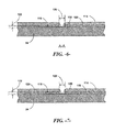
- Fig. 7 depicts an embodiment wherein the attachment layer 118 includes a layer of resin or putty 119 between the strip/sheet material layer 120 (such as a foam-based layer as described above) and the underlying blade composite material.
- the overall thickness 122 of the attachment layer 118 is preferably within the limits discussed above in this embodiment.
- Fig. 8 depicts an embodiment wherein the attachment layer 118 includes a layer of resin or putty 119 between the strip/sheet material layer 120 (such as a foam-based layer as described above) and the overlying blade accessory base portion 114.
Abstract
Description
- The present disclosure relates in general to wind turbine rotor blades, and more particularly to a system for attaching an accessory component to a wind turbine rotor blade.
- Wind power is considered one of the cleanest, most environmentally friendly energy sources presently available, and wind turbines have gained increased attention in this regard. A modem wind turbine typically includes a tower, generator, gearbox, nacelle, and one or more rotor blades. The rotor blades capture kinetic energy of wind using known foil principles. The rotor blades transmit the kinetic energy in the form of rotational energy so as to turn a shaft coupling the rotor blades to a gearbox, or if a gearbox is not used, directly to the generator. The generator then converts the mechanical energy to electrical energy that may be deployed to a utility grid.
- In many cases, various accessory components are attached to the rotor blades of wind turbines to perform various functions during operation of the wind turbine. Frequently, these components are attached adjacent to the trailing edges of the rotor blades. For example, noise reducers or flow enhancers may be attached to the trailing edges of the rotor blades to reduce the noise and increase the aerodynamic efficiency of the rotor blade.
- Typical prior art noise reducers are often provided as serrated strips mounted directly to a trailing edge surface of the rotor blade using glue or another suitable adhesive. This configuration may have a variety of disadvantages. For example, the noise reducers are generally mounted to rotor blades during manufacturing before the rotor blades are transported to the wind turbine site. The noise reducers are thus easily susceptible to damage during transportation. Attachment of the serrated strips to the stiffer blade material using a relatively high modulus adhesive or glue results in high shear stresses being imparted to the strips during normal operational bending or twisting of the rotor blades, which makes the strips prone to cracking and delamination. Additionally, the adhesives used to mount the blade accessories make replacement of the accessories difficult, expensive, and time consuming.
- Thus, an improved attachment system for wind turbine rotor blade accessories, such as serrated noise reducer strips, would be desired. For example, an attachment system that allows for on-site mounting to a rotor blade would be advantageous. Further, a system that reduces damage to the accessories from high shear stresses would be advantageous, as well as a system that allows for relatively easy, cost-effective, and efficient replacement.
- Various aspects and advantages of the invention will be set forth in part in the following description, or may be clear from the description, or may be learned through practice of the invention.
- In one embodiment, a rotor blade assembly for a wind turbine includes a rotor blade having surfaces that define a pressure side, a suction side, a leading edge, and a trailing edge extending between a blade tip and a root. A strip-member blade accessory is mounted to one of the rotor blade surfaces that flexes or stretches (referred to generically as "stretches" herein) under normal operating conditions of the wind turbine. The blade accessory includes a base portion that may be in the form of a plate-like member. An attachment layer is provided to connect the base portion to the rotor blade surface, wherein the attachment layer has a lower shear modulus than the base portion to allow for shear slippage between the base portion and the underlying rotor blade surface. The shear modulus is, in certain embodiments, within the range of 50kPa - 1MPa. With this unique configuration, the blade accessory is essentially isolated from sheer stresses resulting from stretching of the underlying substrate. The intermediate attachment layer allows for relative sheer movement or slippage between the components such that stresses that might otherwise cause cracking or delamination of the blade accessory are not significantly imparted to the blade accessory.
- In a particular embodiment, the attachment layer may be a foam-based strip material (e.g., a tape or sheet material) with adhesive on both interface sides thereof, such as a
- Very High Bond (VHB) or SAFT (Solar Acrylic Foam Tape) foam-based tape. The attachment layer may have a particular thickness that provides the sheer slippage characteristic without adding a detrimental height aspect that could adversely affect the aerodynamic performance of the blade. For example, the attachment layer may have a thickness between 0.5 mm - 5.0 mm.
- In an advantageous embodiment, the strip member blade accessory is segmented into smaller, adjacently aligned components. For example, the strip-member blade accessory may be defined by like segments having a length of between 0.3 meters to less than 2.0 meters. In a certain embodiment, the segments have a length of less than 1.0 meters.
- The strip-member blade accessory may, in one embodiment, be attached along the trailing edge, leading edge, or any other location on the rotor blade. The blade accessory may include a plurality of like segments attached along the trailing edge of the rotor blade with a gap between edges of adjacent segments. Certain embodiments may include fillet seals in the gap between the edges of adjacent segments.
- It should be appreciated that the blade accessory is not limited by design or function. For example, in one embodiment, the accessory may be a noise reducer accessory having a plurality of serrations extending from the base plate. In another embodiment, the accessory may include a base plate with a plurality of aerodynamic features extending therefrom.
- Various features, aspects and advantages of the present invention will become better understood with reference to the following description and appended claims. The accompanying drawings, which are incorporated in and constitute a part of this specification, illustrate embodiments of the invention and, together with the description, serve to explain the principles of the invention. In the drawings:
-
Fig. 1 is a perspective view of one embodiment of a wind turbine of the present disclosure; -
Fig. 2 is a perspective view of one embodiment of a rotor blade assembly of the present disclosure; -
Fig. 3 is a perspective view of another embodiment of a rotor blade assembly of the present disclosure; -
Fig. 4 is a cross-sectional view of another embodiment of a rotor blade assembly of the present disclosure; -
Fig 5 is an enlarged partial cut-away view of an embodiment of a rotor blade assembly of the present disclosure; -
Fig. 6 is a cross-sectional view taken along the lines indicated inFig. 5 ; -
Fig. 7 is a cross-sectional view of an alternative embodiment of a rotor blade assembly; -
Fig. 8 is a cross-sectional view of still another alternative embodiment of a rotor blade assembly; and -
Fig. 9 is an enlarged partial cut-away view of an alternative embodiment of a rotor blade assembly of the present disclosure. - Reference now will be made in detail to embodiments of the invention, one or more examples of which are illustrated in the drawings. Each example is provided by way of explanation of the invention, not limitation of the invention. In fact, it will be apparent to those skilled in the art that various modifications and variations can be made in the present invention without departing from the scope or spirit of the invention. For instance, features illustrated or described as part of one embodiment can be used with another embodiment to yield a still further embodiment. Thus, it is intended that the present invention covers such modifications and variations as come within the scope of the appended claims and their equivalents.
-
Fig. 1 illustrates awind turbine 10 of conventional construction. Thewind turbine 10 includes atower 12 with anacelle 14 mounted thereon. A plurality ofrotor blades 16 are mounted to arotor hub 18, which is in turn connected to a main flange that turns a main rotor shaft. The wind turbine power generation and control components are housed within thenacelle 14. The view ofFig. 1 is provided for illustrative purposes only to place the present invention in an exemplary field of use. It should be appreciated that the invention is not limited to any particular type of wind turbine configuration. - Referring to
Fig. 2 , arotor blade 16 according to the present disclosure may include surfaces defining apressure side 22 and asuction side 24 extending between a leadingedge 26 and atrailing edge 28. Therotor blade 16 may extend from ablade tip 32 to ablade root 34. The surfaces defining thepressure side 22,suction side 24, leadingedge 26, andtrailing edge 28 further define a rotor blade interior. - In some embodiments, the
rotor blade 16 may include a plurality of individual blade segments aligned in an end-to-end order from theblade tip 32 to theblade root 34. Each of the individual blade segments may be uniquely configured so that the plurality of blade segments define acomplete rotor blade 16 having a designed aerodynamic profile, length, and other desired characteristics. For example, each of the blade segments may have an aerodynamic profile that corresponds to the aerodynamic profile of adjacent blade segments. Thus, the aerodynamic profiles of the blade segments may form a continuous aerodynamic profile of therotor blade 16. Alternatively, therotor blade 16 may be formed as a singular, unitary blade having the designed aerodynamic profile, length, and other desired characteristics. - The
rotor blade 16 may, in exemplary embodiments, be curved. Curving of therotor blade 16 may entail bending therotor blade 16 in a generally flap-wise direction and/or in a generally edgewise direction. The flap-wise direction may generally be construed as the direction (or the opposite direction) in which the aerodynamic lift acts on therotor blade 16. The edgewise direction is generally perpendicular to the flap-wise direction. Flap-wise curvature of therotor blade 16 is also known as prebend, while edgewise curvature is also known as sweep. Thus, acurved rotor blade 16 may be pre-bent and/or swept. Curving may enable therotor blade 16 to better withstand flap-wise and edgewise loads during operation of thewind turbine 10, and may further provide clearance for therotor blade 16 from thetower 12 during operation of thewind turbine 10. - The
rotor blade 16 may further define a pitch axis 40 (Figs. 2 and 3 ) relative to therotor hub 18 of thewind turbine 10. For example, thepitch axis 40 may extend generally perpendicularly to therotor hub 18 andblade root 34 through the center of theblade root 34. A pitch angle or blade pitch of therotor blade 16, i.e., an angle that determines a perspective of therotor blade 16 with respect to the air flow past thewind turbine 10, may be defined by rotation of therotor blade 16 about thepitch axis 40. - The
rotor blade 16 may further definechord 42 and aspan 44. As shown inFigs. 2 and 3 , thechord 42 may vary throughout thespan 44 of therotor blade 16. Thus, as discussed below, alocal chord 46 may be defined for therotor blade 16 at any point on therotor blade 16 along thespan 44. - Referring to
Figs. 2 and 3 , the present disclosure relates to arotor blade assembly 100 that includes a strip-member blade accessory 110 configured on therotor blade 16. Theblade accessory 110 is an elongated member that is attached to one of the blade surfaces for any intended functionality. For example, known structures are attached to windturbine rotor blades 16 to enhance the aerodynamic efficiency/performance of the blades. Other known structures are attached to reduce the noise generated by theblade 16. It should be appreciated that the present invention is not limited to any particular type or configuration ofblade accessory 110. - In the illustrated embodiments, the strip-
member blade accessory 110 is anoise reducer 116 attached to thepressure side 22 orsuction side 24 of theblade 16 along a portion of the trailingedge 28. Alternatively, thenoise reducer 110 may be configured on a surface of therotor blade 16 adjacent the leadingedge 26 of therotor blade 16, or adjacent thetip 32 or theroot 34 of therotor blade 16, or at any other suitable position on therotor blade 16. Such devices are generally used to reduce the aerodynamic noise being emitted from therotor blade 16 during operation of thewind turbine 10 and/or may increase the aerodynamic efficiency/performance of therotor blade 16. - The
blade accessory 110 may be formed from various materials. A conventional construction is a relatively stiff fiberglass laminate material that is "stiffer" than the underlying shell material of thepressure 22 orsuction 24 sides. As explained above, with conventional attachment means, stretching or flexing of the blade surfaces during normal operating conditions of thewind turbine 10 may impart significant sheer stresses to theblade accessory 110, resulting in any combination of cracking, de-bonding, or delamination of the blade accessory. - The
blade accessory 110 includes abase portion 114 attached to the blade surface. This base portion may be defined as a generally continuous plate-like structure that presents a generally flat, planar surface that contours and adheres to the mating blade surface. Functional components may be formed integral with thebase portion 114, or separately attached t the base portion. In thenoise reducer 116 embodiment illustrated in the figures, a plurality ofserrations 112 extend from thebase portion 114. While in exemplary embodiments theserrations 112 are generally V-shaped, in alternative embodiments theserrations 112 may be U-shaped, or may have any other shape or configuration suitable for reducing the noise being emitted from and/or increasing the aerodynamic efficiency/performance of therotor blade 16 during operation of thewind turbine 10. For example, in some non-limiting embodiments, theserrations 112 may be generally sinusoidal or squared-sinusoidal. - Referring to
Figs. 4 through 6 , anattachment layer 118 is provided to connect thebase portion 114 of theblade accessory 110 to the rotor blade surface. Thisattachment layer 118 has a lower shear modulus than thebase portion 114 to allow for shear slippage between the relativelystiff base portion 114 and the underlying rotor blade surface. It should be appreciated that the properties of the attachment layer will vary depending on numerous factors, such as blade material, blade accessory material, blade size, blade loads, and so forth. For commercial grade wind turbines, the shear modulus is, in certain embodiments, within the range of 50Kpa - 1MPa. With this unique configuration, theblade accessory 110 is essentially isolated from sheer stresses resulting from stretching of the underlying blade substrate. Theintermediate attachment layer 118 allows for relative sheer movement or slippage between the components such that stresses that might otherwise cause cracking or delamination of theblade accessory 110 are not significantly imparted to theblade accessory 110. - In a particular embodiment, the
attachment layer 118 may be a double-sided adhesive sheet orstrip material 120, such as a Very High Bond (VHB)/SAFT (Solar Acrylic Foam Tape) foam-based tape. Various examples of VHB/SAFT foam-based materials are commercially available, for example from 3M Corporation of St. Paul, Minnesota, USA. Thefoam attachment layer 120 will sheer a small but defined amount with flexing of the underlying blade surfaces, thus reducing sheer stresses in theblade accessory 110. - The
attachment layer 118 may be selected to have a particular thickness 122 (Fig. 6 ) that provides the desired sheer slippage or strain isolation characteristic without adding a detrimental height aspect that could adversely affect the aerodynamic performance of the blade. For example, the adhesive tape may have a thickness between 0.5 mm - 5.0 mm. - The
attachment layer 118 may be applied as a continuous strip between thebase portion 114 and underlying blade surface, as depicted inFig. 5 , or may be applied in a discontinuous pattern. For example, in the embodiment depicted inFig. 9 , theattachment layer 118 includes a plurality of distinct strips 120 (e.g., tape or sheet strips) with a chord-wise gap between adjacent strips. In other embodiments, the attachment layer may include span-wise gaps betweendistinct strips 120. - It has also been determined by the present inventors that the length of the strip-
member blade accessory 110 in combination with theattachment layer 118 is a factor that can be varied to reduce sheer stresses in theblade accessory 110. For example, fatigue testing has shown that, for the same type ofattachment layer 118, at a certain length theblade accessory 110 will de-bond from the blade surface. In an advantageous embodiment, the stripmember blade accessory 110 has a length 124 (Fig. 2 ) of between 0.1 meters to less than 2.0 meters. In a certain embodiment, theblade accessory 110 has a length of less than 1.0 meters. - Referring to
Figs. 3 through 6 , an embodiment of ablade assembly 100 is illustrated wherein theblade accessory 110 is defined by a plurality ofstrip components 126 longitudinally aligned and attached along an edge of theblade 16 with a gap 128 (Fig. 6 ) betweenadjacent components 126. Theshorter components 126 have the reduced sheer stress advantages and combine to provide aneffective noise reducer 112 along a substantial portion of the trailingedge 28. Each of thecomponents 126 may have a length of between 0.1 meters to less than 2.0 meters. In the illustrated embodiment depicted inFigs. 5 and6 , the attachment layer 118 (e.g., tape 120) is discontinuous along the length of thecomponents 126 and does not bridge therespective gaps 128. Thegaps 128 allow for relative sheer slippage between thedifferent components 126 with less slippage and sheer strain on the individual tape sections. In a particular embodiment, thegap 128 may be, for example, 5 mm. Referring toFig. 6 , fillet seals 130 may be provided at the edges of therespective segments 126 to protect theattachment layer 118 from moisture or other elements. Theseals 130 may be, for example, any type of flexible caulking material. -
Fig. 7 depicts an embodiment wherein theattachment layer 118 includes a layer of resin orputty 119 between the strip/sheet material layer 120 (such as a foam-based layer as described above) and the underlying blade composite material. Theoverall thickness 122 of theattachment layer 118 is preferably within the limits discussed above in this embodiment. - Similarly,
Fig. 8 depicts an embodiment wherein theattachment layer 118 includes a layer of resin orputty 119 between the strip/sheet material layer 120 (such as a foam-based layer as described above) and the overlying bladeaccessory base portion 114. - This written description uses examples to disclose the invention, including the preferred mode, and also to enable any person skilled in the art to practice the invention, including making and using any devices or systems and performing any incorporated methods. The patentable scope of the invention is defined by the claims, and may include other examples that occur to those skilled in the art. Such other examples are intended to be within the scope of the claims if they include structural elements that do not differ from the literal language of the claims, or if they include equivalent structural elements with insubstantial differences from the literal languages of the claims.
- Various aspects and embodiments of the present invention are defined by the following numbered clauses:
- 1. A rotor blade assembly for a wind turbine, comprising:
- a rotor blade having surfaces defining a pressure side, a suction side, a leading edge, and a trailing edge extending between a tip and a root;
- a strip-member blade accessory mounted to one of the rotor blade surfaces that stretches under normal operating conditions of the wind turbine, the blade accessory comprising a base portion; and
- an attachment layer connecting the base portion to the rotor blade surface, the attachment layer having a lower shear modulus than the base portion to allow for shear slippage between the base portion and the underlying rotor blade surface.
- 2. The rotor blade assembly as in clause 1, wherein the attachment layer comprises a foam-based strip member with adhesive on opposite interface sides thereof.
- 3. The rotor blade assembly as in any preceding clause, wherein the attachment layer comprises a Very High Bond (VHB) or SAFT (Solar Acrylic Foam Tape) foam-based strip material.
- 4. The rotor blade assembly as in any preceding clause, wherein the attachment layer has a thickness between 0.5 mm - 5.0 mm.
- 5. The rotor blade assembly as in any preceding clause, wherein the strip-member blade accessory has a length between 0.3 meters to less than 2.0 meters.
- 6. The rotor blade assembly as in any preceding clause, wherein the strip-member blade accessory has a length of less than 1.0 meters.
- 7. The rotor blade assembly as in any preceding clause, wherein the strip-member blade accessory is attached along the trailing edge of the rotor blade.
- 8. The rotor blade assembly as in any preceding clause, wherein the strip member blade accessory comprises a plurality of the strip components attached along an edge of the rotor blade with a gap between edges of adjacent strip components.
- 9. The rotor blade assembly as in any preceding clause, wherein the strip components have a length between 0.3 meters to less than 2.0 meters.
- 10. The rotor blade assembly as in any preceding clause, further comprising fillet seals in the gap between the edges of adjacent strip components.
- 11. The rotor blade assembly as in any preceding clause, wherein the blade accessory is a noise reducer accessory having a plurality of serrations extending from the base portion.
- 12. The rotor blade assembly as in any preceding clause, further comprising a putty or resin layer disposed between the attachment layer and at least one of the rotor blade surface or the blade accessory base portion.
- 13. A rotor blade assembly for a wind turbine, comprising:
- a rotor blade having surfaces defining a pressure side, a suction side, a leading edge, and a trailing edge extending between a tip and a root;
- a strip-member segment attached along the trailing edge surface of the rotor blade, the strip-member segment comprising a plurality of longitudinally aligned strip components having a base portion and a plurality of serrations extending from the base portion; and
- an attachment layer connecting the base portions to the trailing edge rotor blade surface, the attachment layer having a lower shear modulus than the base portion to allow for shear slippage between the base portion and the underlying trailing edge rotor blade surface.
- 14. The rotor blade assembly as in any preceding clause, wherein the plurality of strip components have a length of less than 1.0 meters.
- 15. The rotor blade assembly as in any preceding clause, further comprising a gap between edges of adjacent strip components and fillet seals disposed in the gaps.
- 16. The rotor blade assembly as in any preceding clause, wherein the attachment layer comprises a foam-based strip material with adhesive on opposite interface sides thereof.
- 17. The rotor blade assembly as in any preceding clause, wherein the adhesive tape comprises a Very High Bond (VHB) or SAFT (Solar Acrylic Foam Tape) foam-based strip material.
- 18. The rotor blade assembly as in any preceding clause, wherein the attachment layer has a thickness between 0.5 mm - 5.0 mm.
- 19. The rotor blade assembly as in any preceding clause, further comprising a putty or resin layer disposed between the attachment layer and at least one of the rotor blade trailing edge surface or the strip member base portion.
Claims (15)
- A rotor blade assembly (100) for a wind turbine (10), comprising:a rotor blade (16) having surfaces defining a pressure side, a suction side, a leading edge, and a trailing edge extending between a tip and a root;a strip-member blade accessory (110) mounted to one of the rotor blade surfaces that stretches under normal operating conditions of the wind turbine (10), the blade accessory (110) comprising a base portion (114); andan attachment layer (118) connecting the base portion (114) to the rotor blade surface, the attachment layer (118) having a lower shear modulus than the base portion (114) to allow for shear slippage between the base portion and the underlying rotor blade surface.
- The rotor blade assembly (100) as in claim 1, wherein the attachment layer (118) comprises a foam-based strip member with adhesive on opposite interface sides thereof.
- The rotor blade assembly (100) as in claim 2, wherein the attachment layer (118) comprises a Very High Bond (VHB) or SAFT (Solar Acrylic Foam Tape) foam-based strip material.
- The rotor blade assembly (100) as in any preceding claim, wherein the attachment layer (118) has a thickness between 0.5 mm - 5.0 mm.
- The rotor blade assembly (100) as in any preceding claim, wherein the strip-member blade accessory (110) has a length between 0.3 meters to less than 2.0 meters.
- The rotor blade assembly (100) as in any preceding claim, wherein the strip-member blade accessory (110) has a length of less than 1.0 meters.
- The rotor blade assembly (100) as in any preceding claim, wherein the strip-member blade accessory (110) is attached along the trailing edge of the rotor blade (16).
- The rotor blade assembly (100) as in any preceding claim, wherein the strip member blade accessory (110) comprises a plurality of strip components (126) attached along an edge of the rotor blade (16) with a gap between edges of adjacent strip components.
- The rotor blade assembly (100) as in claim 8, wherein the strip components (126) have a length between 0.3 meters to less than 2.0 meters.
- The rotor blade assembly (100) as in any preceding claim, further comprising fillet seals (130) in the gap (128) between the edges of adjacent strip components.
- The rotor blade assembly (100) as in any preceding claim, wherein the blade accessory (110) is a noise reducer accessory having a plurality of serrations extending from the base portion.
- The rotor blade assembly (100) as in any preceding claim, further comprising a putty or resin layer (119) disposed between the attachment layer (118) and at least one of the rotor blade surface or the blade accessory base portion (114).
- A rotor blade assembly (100) for a wind turbine (10), comprising:a rotor blade (16) having surfaces defining a pressure side, a suction side, a leading edge, and a trailing edge extending between a tip and a root;a strip-member segment (110) attached along the trailing edge surface of the rotor blade, the strip-member segment comprising a plurality of longitudinally aligned strip components (126) having a base portion and a plurality of serrations extending from the base portion; andan attachment layer (118) connecting the base portions to the trailing edge rotor blade surface, the attachment layer having a lower shear modulus than the base portion to allow for shear slippage between the base portion and the underlying trailing edge rotor blade surface.
- The rotor blade assembly (100) as in claim 13, wherein the plurality of strip components (126) have a length of less than 1.0 meters.
- The rotor blade assembly as in claim 13 or claim 14, further comprising a gap (128) between edges of adjacent strip components (126) and fillet seals (130) disposed in the gaps (128).
Applications Claiming Priority (1)
| Application Number | Priority Date | Filing Date | Title |
|---|---|---|---|
| US13/609,719 US9458821B2 (en) | 2012-09-11 | 2012-09-11 | Attachment system for a wind turbine rotor blade accessory |
Publications (3)
| Publication Number | Publication Date |
|---|---|
| EP2706228A2 true EP2706228A2 (en) | 2014-03-12 |
| EP2706228A3 EP2706228A3 (en) | 2018-04-18 |
| EP2706228B1 EP2706228B1 (en) | 2021-03-17 |
Family
ID=49115404
Family Applications (1)
| Application Number | Title | Priority Date | Filing Date |
|---|---|---|---|
| EP13183019.2A Active EP2706228B1 (en) | 2012-09-11 | 2013-09-04 | Rotor blade assembly for a wind turbine |
Country Status (6)
| Country | Link |
|---|---|
| US (1) | US9458821B2 (en) |
| EP (1) | EP2706228B1 (en) |
| AU (1) | AU2013222047B2 (en) |
| CA (1) | CA2826409C (en) |
| DK (1) | DK2706228T3 (en) |
| ES (1) | ES2874815T3 (en) |
Cited By (2)
| Publication number | Priority date | Publication date | Assignee | Title |
|---|---|---|---|---|
| CN110177935A (en) * | 2017-01-12 | 2019-08-27 | Lm风力发电国际技术有限公司 | Wind turbine blade including rear denoising device |
| EP3169897B1 (en) | 2014-07-17 | 2022-10-19 | Wobben Properties GmbH | Wind-turbine rotor blade, rotor blade trailing edge, method for producing a wind-turbine rotor blade, and wind turbine |
Families Citing this family (29)
| Publication number | Priority date | Publication date | Assignee | Title |
|---|---|---|---|---|
| US9458821B2 (en) * | 2012-09-11 | 2016-10-04 | General Electric Company | Attachment system for a wind turbine rotor blade accessory |
| US9562513B2 (en) * | 2013-05-03 | 2017-02-07 | General Electric Company | Wind turbine rotor blade assembly with surface features |
| EP2896961B1 (en) * | 2014-01-20 | 2020-11-25 | Siemens Gamesa Renewable Energy A/S | De-lamination indicator |
| EP2908001B1 (en) * | 2014-02-12 | 2016-09-21 | Siemens Aktiengesellschaft | Means for alleviating strain on a wind turbine rotor blade |
| DE102014206345A1 (en) * | 2014-04-02 | 2015-10-08 | Wobben Properties Gmbh | A method of attaching a serrated trailing edge to a blade trailing edge of a rotor blade |
| CA2956415C (en) * | 2014-08-05 | 2023-02-07 | Lm Wp Patent Holding A/S | Wind turbine blade provided with surface mounted device |
| US10100805B2 (en) * | 2015-10-12 | 2018-10-16 | General Electric Compant | Tip extension assembly for a wind turbine rotor blade |
| US10240576B2 (en) * | 2015-11-25 | 2019-03-26 | General Electric Company | Wind turbine noise reduction with acoustically absorbent serrations |
| EP3181895A1 (en) * | 2015-12-17 | 2017-06-21 | LM WP Patent Holding A/S | Splitter plate arrangement for a serrated wind turbine blade |
| ES2715511T3 (en) * | 2016-02-12 | 2019-06-04 | Lm Wp Patent Holding As | Serrated outlet edge panel for a wind turbine blade |
| US10487796B2 (en) | 2016-10-13 | 2019-11-26 | General Electric Company | Attachment methods for surface features of wind turbine rotor blades |
| US10443579B2 (en) | 2016-11-15 | 2019-10-15 | General Electric Company | Tip extensions for wind turbine rotor blades and methods of installing same |
| US10830206B2 (en) | 2017-02-03 | 2020-11-10 | General Electric Company | Methods for manufacturing wind turbine rotor blades and components thereof |
| US11098691B2 (en) | 2017-02-03 | 2021-08-24 | General Electric Company | Methods for manufacturing wind turbine rotor blades and components thereof |
| US10711629B2 (en) | 2017-09-20 | 2020-07-14 | Generl Electric Company | Method of clearance control for an interdigitated turbine engine |
| US10458267B2 (en) | 2017-09-20 | 2019-10-29 | General Electric Company | Seal assembly for counter rotating turbine assembly |
| US10865769B2 (en) | 2017-11-21 | 2020-12-15 | General Electric Company | Methods for manufacturing wind turbine rotor blade panels having printed grid structures |
| US11040503B2 (en) | 2017-11-21 | 2021-06-22 | General Electric Company | Apparatus for manufacturing composite airfoils |
| US10773464B2 (en) | 2017-11-21 | 2020-09-15 | General Electric Company | Method for manufacturing composite airfoils |
| US11390013B2 (en) | 2017-11-21 | 2022-07-19 | General Electric Company | Vacuum forming mold assembly and associated methods |
| US10821652B2 (en) | 2017-11-21 | 2020-11-03 | General Electric Company | Vacuum forming mold assembly and method for creating a vacuum forming mold assembly |
| US11248582B2 (en) | 2017-11-21 | 2022-02-15 | General Electric Company | Multiple material combinations for printed reinforcement structures of rotor blades |
| US10920745B2 (en) | 2017-11-21 | 2021-02-16 | General Electric Company | Wind turbine rotor blade components and methods of manufacturing the same |
| US11668275B2 (en) | 2017-11-21 | 2023-06-06 | General Electric Company | Methods for manufacturing an outer skin of a rotor blade |
| US10913216B2 (en) | 2017-11-21 | 2021-02-09 | General Electric Company | Methods for manufacturing wind turbine rotor blade panels having printed grid structures |
| US11035339B2 (en) | 2018-03-26 | 2021-06-15 | General Electric Company | Shear web assembly interconnected with additive manufactured components |
| US10821696B2 (en) | 2018-03-26 | 2020-11-03 | General Electric Company | Methods for manufacturing flatback airfoils for wind turbine rotor blades |
| US10746157B2 (en) * | 2018-08-31 | 2020-08-18 | General Electric Company | Noise reducer for a wind turbine rotor blade having a cambered serration |
| US11428160B2 (en) | 2020-12-31 | 2022-08-30 | General Electric Company | Gas turbine engine with interdigitated turbine and gear assembly |
Family Cites Families (33)
| Publication number | Priority date | Publication date | Assignee | Title |
|---|---|---|---|---|
| USRE19412E (en) | 1935-01-01 | Aircraft and control thereof | ||
| US2450440A (en) | 1944-12-19 | 1948-10-05 | Roscoe H Mills | Propeller blade construction |
| US3528753A (en) | 1968-06-14 | 1970-09-15 | United Aircraft Corp | Helicopter blade with non-homogeneous structural spar |
| US3586460A (en) | 1969-05-14 | 1971-06-22 | Us Air Force | Rotor blade variable modulus trailing edge |
| US4329119A (en) | 1977-08-02 | 1982-05-11 | The Boeing Company | Rotor blade internal damper |
| FR2542695B1 (en) | 1983-03-18 | 1985-07-26 | Aerospatiale | MULTI-BLADE PROPELLER WITH VARIABLE PITCH WITH BLADES IN COMPOSITE MATERIALS INDIVIDUALLY REMOVABLE, PROCESS FOR MANUFACTURING SUCH BLADES AND BLADES THUS REALIZED |
| US5346367A (en) | 1984-12-21 | 1994-09-13 | United Technologies Corporation | Advanced composite rotor blade |
| US5088665A (en) | 1989-10-31 | 1992-02-18 | The United States Of America As Represented By The Administrator Of The National Aeronautics And Space Administration | Serrated trailing edges for improving lift and drag characteristics of lifting surfaces |
| US7059833B2 (en) | 2001-11-26 | 2006-06-13 | Bonus Energy A/S | Method for improvement of the efficiency of a wind turbine rotor |
| US7637721B2 (en) | 2005-07-29 | 2009-12-29 | General Electric Company | Methods and apparatus for producing wind energy with reduced wind turbine noise |
| US7458777B2 (en) | 2005-09-22 | 2008-12-02 | General Electric Company | Wind turbine rotor assembly and blade having acoustic flap |
| ES2318925B1 (en) | 2005-09-22 | 2010-02-11 | GAMESA INNOVATION & TECHNOLOGY, S.L. | AEROGENERATOR WITH A BLADE ROTOR THAT REDUCES NOISE. |
| EP2027390B2 (en) * | 2006-06-09 | 2020-07-01 | Vestas Wind Systems A/S | A wind turbine blade and a pitch controlled wind turbine |
| ES2310958B1 (en) * | 2006-09-15 | 2009-11-10 | GAMESA INNOVATION & TECHNOLOGY, S.L. | OPTIMIZED AEROGENERATOR SHOVEL. |
| US20090074585A1 (en) | 2007-09-19 | 2009-03-19 | General Electric Company | Wind turbine blades with trailing edge serrations |
| US8075278B2 (en) | 2009-05-21 | 2011-12-13 | Zuteck Michael D | Shell structure of wind turbine blade having regions of low shear modulus |
| US8079819B2 (en) | 2009-05-21 | 2011-12-20 | Zuteck Michael D | Optimization of premium fiber material usage in wind turbine spars |
| US8083488B2 (en) * | 2010-08-23 | 2011-12-27 | General Electric Company | Blade extension for rotor blade in wind turbine |
| US8038407B2 (en) | 2010-09-14 | 2011-10-18 | General Electric Company | Wind turbine blade with improved trailing edge bond |
| EP2444658B1 (en) * | 2010-10-21 | 2016-10-19 | Siemens Aktiengesellschaft | Method to retrofit a blade of a wind turbine |
| US8523515B2 (en) * | 2010-11-15 | 2013-09-03 | General Electric Company | Noise reducer for rotor blade in wind turbine |
| US8047799B2 (en) * | 2010-12-13 | 2011-11-01 | General Electric Company | Wind turbine blades with improved bond line and associated method |
| US20110268558A1 (en) | 2010-12-20 | 2011-11-03 | General Electric Company | Noise reducer for rotor blade in wind turbine |
| DK2484897T3 (en) * | 2011-02-04 | 2014-03-10 | Lm Wind Power As | Vortex generator for a wind turbine and having a base portion with a recess for an adhesive |
| ES2482615T3 (en) * | 2011-02-04 | 2014-08-04 | Lm Wp Patent Holding A/S | Whirlwind generating device with tapered sections for a wind turbine |
| US8414261B2 (en) * | 2011-05-31 | 2013-04-09 | General Electric Company | Noise reducer for rotor blade in wind turbine |
| US8834127B2 (en) * | 2011-09-09 | 2014-09-16 | General Electric Company | Extension for rotor blade in wind turbine |
| US8506250B2 (en) * | 2011-10-19 | 2013-08-13 | General Electric Company | Wind turbine rotor blade with trailing edge extension and method of attachment |
| DE102012000431A1 (en) * | 2012-01-12 | 2013-07-18 | Smart Blade Gmbh | Rotor blade for wind turbine, has aerodynamic element, which is mounted and arranged on surface through pivot joint, and automatically swings at surface of rotor blade at predetermined flow by force of fluid |
| ES2554908T3 (en) * | 2012-02-24 | 2015-12-28 | Siemens Aktiengesellschaft | Arrangement to reduce noise caused by a wind turbine blade |
| DK177533B1 (en) * | 2012-05-25 | 2013-09-08 | Envision Energy Denmark Aps | Trailing edge tape |
| US9458821B2 (en) * | 2012-09-11 | 2016-10-04 | General Electric Company | Attachment system for a wind turbine rotor blade accessory |
| US9556849B2 (en) * | 2013-05-02 | 2017-01-31 | General Electric Company | Attachment system and method for wind turbine vortex generators |
-
2012
- 2012-09-11 US US13/609,719 patent/US9458821B2/en active Active
-
2013
- 2013-09-03 AU AU2013222047A patent/AU2013222047B2/en active Active
- 2013-09-04 ES ES13183019T patent/ES2874815T3/en active Active
- 2013-09-04 DK DK13183019.2T patent/DK2706228T3/en active
- 2013-09-04 EP EP13183019.2A patent/EP2706228B1/en active Active
- 2013-09-05 CA CA2826409A patent/CA2826409C/en active Active
Non-Patent Citations (1)
| Title |
|---|
| None |
Cited By (2)
| Publication number | Priority date | Publication date | Assignee | Title |
|---|---|---|---|---|
| EP3169897B1 (en) | 2014-07-17 | 2022-10-19 | Wobben Properties GmbH | Wind-turbine rotor blade, rotor blade trailing edge, method for producing a wind-turbine rotor blade, and wind turbine |
| CN110177935A (en) * | 2017-01-12 | 2019-08-27 | Lm风力发电国际技术有限公司 | Wind turbine blade including rear denoising device |
Also Published As
| Publication number | Publication date |
|---|---|
| CA2826409C (en) | 2017-03-07 |
| AU2013222047A1 (en) | 2014-03-27 |
| US9458821B2 (en) | 2016-10-04 |
| AU2013222047B2 (en) | 2017-02-16 |
| US20140072440A1 (en) | 2014-03-13 |
| ES2874815T3 (en) | 2021-11-05 |
| CA2826409A1 (en) | 2014-03-11 |
| DK2706228T3 (en) | 2021-06-21 |
| EP2706228B1 (en) | 2021-03-17 |
| EP2706228A3 (en) | 2018-04-18 |
Similar Documents
| Publication | Publication Date | Title |
|---|---|---|
| EP2706228B1 (en) | Rotor blade assembly for a wind turbine | |
| EP2799709B1 (en) | Method for attachment of wind turbine vortex generators | |
| US10584676B2 (en) | Wind turbine rotor blade assembly with surface features | |
| DK178210B1 (en) | Extension for rotor blade in wind turbine | |
| DK178482B1 (en) | Noise reducer for rotor blade in wind turbine | |
| DK177659B1 (en) | Noise reducer for rotor blade in wind turbine | |
| EP3091225B1 (en) | Wind turbine blade and attachment method to install components, such as tip extensions and winglets, to a wind turbine blade | |
| DK178192B1 (en) | Noise reduction device for rotor blades in a wind turbine | |
| US8414261B2 (en) | Noise reducer for rotor blade in wind turbine | |
| AU2013231165B2 (en) | Noise reduction tab and method for wind turbine rotor blade | |
| CA2869803C (en) | Noise reducing extension plate for rotor blade in wind turbine | |
| US20120027588A1 (en) | Root flap for rotor blade in wind turbine | |
| WO2013086667A1 (en) | Wind turbine blade shear web connection assembly | |
| EP3071830A1 (en) | Wind turbine blade with wave shaped trailing edge | |
| DK201200565A (en) | Rotor blade assembly for wind turbine |
Legal Events
| Date | Code | Title | Description |
|---|---|---|---|
| PUAI | Public reference made under article 153(3) epc to a published international application that has entered the european phase |
Free format text: ORIGINAL CODE: 0009012 |
|
| AK | Designated contracting states |
Kind code of ref document: A2 Designated state(s): AL AT BE BG CH CY CZ DE DK EE ES FI FR GB GR HR HU IE IS IT LI LT LU LV MC MK MT NL NO PL PT RO RS SE SI SK SM TR |
|
| AX | Request for extension of the european patent |
Extension state: BA ME |
|
| PUAL | Search report despatched |
Free format text: ORIGINAL CODE: 0009013 |
|
| AK | Designated contracting states |
Kind code of ref document: A3 Designated state(s): AL AT BE BG CH CY CZ DE DK EE ES FI FR GB GR HR HU IE IS IT LI LT LU LV MC MK MT NL NO PL PT RO RS SE SI SK SM TR |
|
| AX | Request for extension of the european patent |
Extension state: BA ME |
|
| RIC1 | Information provided on ipc code assigned before grant |
Ipc: F03D 1/06 20060101AFI20180314BHEP |
|
| STAA | Information on the status of an ep patent application or granted ep patent |
Free format text: STATUS: REQUEST FOR EXAMINATION WAS MADE |
|
| 17P | Request for examination filed |
Effective date: 20181018 |
|
| RBV | Designated contracting states (corrected) |
Designated state(s): AL AT BE BG CH CY CZ DE DK EE ES FI FR GB GR HR HU IE IS IT LI LT LU LV MC MK MT NL NO PL PT RO RS SE SI SK SM TR |
|
| STAA | Information on the status of an ep patent application or granted ep patent |
Free format text: STATUS: EXAMINATION IS IN PROGRESS |
|
| 17Q | First examination report despatched |
Effective date: 20191023 |
|
| GRAP | Despatch of communication of intention to grant a patent |
Free format text: ORIGINAL CODE: EPIDOSNIGR1 |
|
| STAA | Information on the status of an ep patent application or granted ep patent |
Free format text: STATUS: GRANT OF PATENT IS INTENDED |
|
| INTG | Intention to grant announced |
Effective date: 20201111 |
|
| RIN1 | Information on inventor provided before grant (corrected) |
Inventor name: ZHU, QI Inventor name: JACOBSEN, ERIC MORGAN Inventor name: NAGABHUSHANA, PRADEEPA Inventor name: BAKHUIS, JAN WILLEM Inventor name: RIDDELL, SCOTT GABELL Inventor name: BUSBEY, BRUCE CLARK Inventor name: ESSER, JUERGEN |
|
| GRAS | Grant fee paid |
Free format text: ORIGINAL CODE: EPIDOSNIGR3 |
|
| GRAA | (expected) grant |
Free format text: ORIGINAL CODE: 0009210 |
|
| STAA | Information on the status of an ep patent application or granted ep patent |
Free format text: STATUS: THE PATENT HAS BEEN GRANTED |
|
| AK | Designated contracting states |
Kind code of ref document: B1 Designated state(s): AL AT BE BG CH CY CZ DE DK EE ES FI FR GB GR HR HU IE IS IT LI LT LU LV MC MK MT NL NO PL PT RO RS SE SI SK SM TR |
|
| REG | Reference to a national code |
Ref country code: GB Ref legal event code: FG4D |
|
| REG | Reference to a national code |
Ref country code: CH Ref legal event code: EP |
|
| REG | Reference to a national code |
Ref country code: DE Ref legal event code: R096 Ref document number: 602013076273 Country of ref document: DE |
|
| REG | Reference to a national code |
Ref country code: IE Ref legal event code: FG4D |
|
| REG | Reference to a national code |
Ref country code: AT Ref legal event code: REF Ref document number: 1372471 Country of ref document: AT Kind code of ref document: T Effective date: 20210415 |
|
| REG | Reference to a national code |
Ref country code: DK Ref legal event code: T3 Effective date: 20210616 |
|
| REG | Reference to a national code |
Ref country code: LT Ref legal event code: MG9D |
|
| PG25 | Lapsed in a contracting state [announced via postgrant information from national office to epo] |
Ref country code: NO Free format text: LAPSE BECAUSE OF FAILURE TO SUBMIT A TRANSLATION OF THE DESCRIPTION OR TO PAY THE FEE WITHIN THE PRESCRIBED TIME-LIMIT Effective date: 20210617 Ref country code: BG Free format text: LAPSE BECAUSE OF FAILURE TO SUBMIT A TRANSLATION OF THE DESCRIPTION OR TO PAY THE FEE WITHIN THE PRESCRIBED TIME-LIMIT Effective date: 20210617 Ref country code: HR Free format text: LAPSE BECAUSE OF FAILURE TO SUBMIT A TRANSLATION OF THE DESCRIPTION OR TO PAY THE FEE WITHIN THE PRESCRIBED TIME-LIMIT Effective date: 20210317 Ref country code: FI Free format text: LAPSE BECAUSE OF FAILURE TO SUBMIT A TRANSLATION OF THE DESCRIPTION OR TO PAY THE FEE WITHIN THE PRESCRIBED TIME-LIMIT Effective date: 20210317 Ref country code: GR Free format text: LAPSE BECAUSE OF FAILURE TO SUBMIT A TRANSLATION OF THE DESCRIPTION OR TO PAY THE FEE WITHIN THE PRESCRIBED TIME-LIMIT Effective date: 20210618 |
|
| REG | Reference to a national code |
Ref country code: AT Ref legal event code: MK05 Ref document number: 1372471 Country of ref document: AT Kind code of ref document: T Effective date: 20210317 |
|
| REG | Reference to a national code |
Ref country code: NL Ref legal event code: MP Effective date: 20210317 |
|
| PG25 | Lapsed in a contracting state [announced via postgrant information from national office to epo] |
Ref country code: RS Free format text: LAPSE BECAUSE OF FAILURE TO SUBMIT A TRANSLATION OF THE DESCRIPTION OR TO PAY THE FEE WITHIN THE PRESCRIBED TIME-LIMIT Effective date: 20210317 Ref country code: LV Free format text: LAPSE BECAUSE OF FAILURE TO SUBMIT A TRANSLATION OF THE DESCRIPTION OR TO PAY THE FEE WITHIN THE PRESCRIBED TIME-LIMIT Effective date: 20210317 Ref country code: SE Free format text: LAPSE BECAUSE OF FAILURE TO SUBMIT A TRANSLATION OF THE DESCRIPTION OR TO PAY THE FEE WITHIN THE PRESCRIBED TIME-LIMIT Effective date: 20210317 |
|
| PG25 | Lapsed in a contracting state [announced via postgrant information from national office to epo] |
Ref country code: NL Free format text: LAPSE BECAUSE OF FAILURE TO SUBMIT A TRANSLATION OF THE DESCRIPTION OR TO PAY THE FEE WITHIN THE PRESCRIBED TIME-LIMIT Effective date: 20210317 |
|
| PG25 | Lapsed in a contracting state [announced via postgrant information from national office to epo] |
Ref country code: SM Free format text: LAPSE BECAUSE OF FAILURE TO SUBMIT A TRANSLATION OF THE DESCRIPTION OR TO PAY THE FEE WITHIN THE PRESCRIBED TIME-LIMIT Effective date: 20210317 Ref country code: AT Free format text: LAPSE BECAUSE OF FAILURE TO SUBMIT A TRANSLATION OF THE DESCRIPTION OR TO PAY THE FEE WITHIN THE PRESCRIBED TIME-LIMIT Effective date: 20210317 Ref country code: EE Free format text: LAPSE BECAUSE OF FAILURE TO SUBMIT A TRANSLATION OF THE DESCRIPTION OR TO PAY THE FEE WITHIN THE PRESCRIBED TIME-LIMIT Effective date: 20210317 Ref country code: CZ Free format text: LAPSE BECAUSE OF FAILURE TO SUBMIT A TRANSLATION OF THE DESCRIPTION OR TO PAY THE FEE WITHIN THE PRESCRIBED TIME-LIMIT Effective date: 20210317 Ref country code: LT Free format text: LAPSE BECAUSE OF FAILURE TO SUBMIT A TRANSLATION OF THE DESCRIPTION OR TO PAY THE FEE WITHIN THE PRESCRIBED TIME-LIMIT Effective date: 20210317 |
|
| REG | Reference to a national code |
Ref country code: ES Ref legal event code: FG2A Ref document number: 2874815 Country of ref document: ES Kind code of ref document: T3 Effective date: 20211105 |
|
| PG25 | Lapsed in a contracting state [announced via postgrant information from national office to epo] |
Ref country code: IS Free format text: LAPSE BECAUSE OF FAILURE TO SUBMIT A TRANSLATION OF THE DESCRIPTION OR TO PAY THE FEE WITHIN THE PRESCRIBED TIME-LIMIT Effective date: 20210717 Ref country code: RO Free format text: LAPSE BECAUSE OF FAILURE TO SUBMIT A TRANSLATION OF THE DESCRIPTION OR TO PAY THE FEE WITHIN THE PRESCRIBED TIME-LIMIT Effective date: 20210317 Ref country code: PT Free format text: LAPSE BECAUSE OF FAILURE TO SUBMIT A TRANSLATION OF THE DESCRIPTION OR TO PAY THE FEE WITHIN THE PRESCRIBED TIME-LIMIT Effective date: 20210719 Ref country code: PL Free format text: LAPSE BECAUSE OF FAILURE TO SUBMIT A TRANSLATION OF THE DESCRIPTION OR TO PAY THE FEE WITHIN THE PRESCRIBED TIME-LIMIT Effective date: 20210317 Ref country code: SK Free format text: LAPSE BECAUSE OF FAILURE TO SUBMIT A TRANSLATION OF THE DESCRIPTION OR TO PAY THE FEE WITHIN THE PRESCRIBED TIME-LIMIT Effective date: 20210317 |
|
| REG | Reference to a national code |
Ref country code: DE Ref legal event code: R097 Ref document number: 602013076273 Country of ref document: DE |
|
| PLBE | No opposition filed within time limit |
Free format text: ORIGINAL CODE: 0009261 |
|
| STAA | Information on the status of an ep patent application or granted ep patent |
Free format text: STATUS: NO OPPOSITION FILED WITHIN TIME LIMIT |
|
| PG25 | Lapsed in a contracting state [announced via postgrant information from national office to epo] |
Ref country code: AL Free format text: LAPSE BECAUSE OF FAILURE TO SUBMIT A TRANSLATION OF THE DESCRIPTION OR TO PAY THE FEE WITHIN THE PRESCRIBED TIME-LIMIT Effective date: 20210317 |
|
| 26N | No opposition filed |
Effective date: 20211220 |
|
| PG25 | Lapsed in a contracting state [announced via postgrant information from national office to epo] |
Ref country code: SI Free format text: LAPSE BECAUSE OF FAILURE TO SUBMIT A TRANSLATION OF THE DESCRIPTION OR TO PAY THE FEE WITHIN THE PRESCRIBED TIME-LIMIT Effective date: 20210317 |
|
| PG25 | Lapsed in a contracting state [announced via postgrant information from national office to epo] |
Ref country code: IT Free format text: LAPSE BECAUSE OF FAILURE TO SUBMIT A TRANSLATION OF THE DESCRIPTION OR TO PAY THE FEE WITHIN THE PRESCRIBED TIME-LIMIT Effective date: 20210317 |
|
| REG | Reference to a national code |
Ref country code: CH Ref legal event code: PL |
|
| REG | Reference to a national code |
Ref country code: BE Ref legal event code: MM Effective date: 20210930 |
|
| PG25 | Lapsed in a contracting state [announced via postgrant information from national office to epo] |
Ref country code: IS Free format text: LAPSE BECAUSE OF FAILURE TO SUBMIT A TRANSLATION OF THE DESCRIPTION OR TO PAY THE FEE WITHIN THE PRESCRIBED TIME-LIMIT Effective date: 20210717 Ref country code: MC Free format text: LAPSE BECAUSE OF FAILURE TO SUBMIT A TRANSLATION OF THE DESCRIPTION OR TO PAY THE FEE WITHIN THE PRESCRIBED TIME-LIMIT Effective date: 20210317 |
|
| PG25 | Lapsed in a contracting state [announced via postgrant information from national office to epo] |
Ref country code: LU Free format text: LAPSE BECAUSE OF NON-PAYMENT OF DUE FEES Effective date: 20210904 Ref country code: IE Free format text: LAPSE BECAUSE OF NON-PAYMENT OF DUE FEES Effective date: 20210904 Ref country code: BE Free format text: LAPSE BECAUSE OF NON-PAYMENT OF DUE FEES Effective date: 20210930 |
|
| PG25 | Lapsed in a contracting state [announced via postgrant information from national office to epo] |
Ref country code: LI Free format text: LAPSE BECAUSE OF NON-PAYMENT OF DUE FEES Effective date: 20210930 Ref country code: CH Free format text: LAPSE BECAUSE OF NON-PAYMENT OF DUE FEES Effective date: 20210930 |
|
| PG25 | Lapsed in a contracting state [announced via postgrant information from national office to epo] |
Ref country code: HU Free format text: LAPSE BECAUSE OF FAILURE TO SUBMIT A TRANSLATION OF THE DESCRIPTION OR TO PAY THE FEE WITHIN THE PRESCRIBED TIME-LIMIT; INVALID AB INITIO Effective date: 20130904 |
|
| P01 | Opt-out of the competence of the unified patent court (upc) registered |
Effective date: 20230522 |
|
| PG25 | Lapsed in a contracting state [announced via postgrant information from national office to epo] |
Ref country code: CY Free format text: LAPSE BECAUSE OF FAILURE TO SUBMIT A TRANSLATION OF THE DESCRIPTION OR TO PAY THE FEE WITHIN THE PRESCRIBED TIME-LIMIT Effective date: 20210317 |
|
| PGFP | Annual fee paid to national office [announced via postgrant information from national office to epo] |
Ref country code: GB Payment date: 20230823 Year of fee payment: 11 |
|
| PGFP | Annual fee paid to national office [announced via postgrant information from national office to epo] |
Ref country code: FR Payment date: 20230822 Year of fee payment: 11 Ref country code: DK Payment date: 20230822 Year of fee payment: 11 Ref country code: DE Payment date: 20230822 Year of fee payment: 11 |
|
| REG | Reference to a national code |
Ref country code: GB Ref legal event code: 732E Free format text: REGISTERED BETWEEN 20231123 AND 20231129 |
|
| REG | Reference to a national code |
Ref country code: DE Ref legal event code: R082 Ref document number: 602013076273 Country of ref document: DE Representative=s name: ZIMMERMANN & PARTNER PATENTANWAELTE MBB, DE Ref country code: DE Ref legal event code: R082 Ref document number: 602013076273 Country of ref document: DE Ref country code: DE Ref legal event code: R081 Ref document number: 602013076273 Country of ref document: DE Owner name: LM WIND POWER A/S, DK Free format text: FORMER OWNER: GENERAL ELECTRIC COMPANY, SCHENECTADY, NY, US |
|
| PGFP | Annual fee paid to national office [announced via postgrant information from national office to epo] |
Ref country code: ES Payment date: 20231002 Year of fee payment: 11 |
|
| REG | Reference to a national code |
Ref country code: DE Ref legal event code: R082 Ref document number: 602013076273 Country of ref document: DE Representative=s name: ZIMMERMANN & PARTNER PATENTANWAELTE MBB, DE |