EP2705927A1 - Air control device and air control method - Google Patents
Air control device and air control method Download PDFInfo
- Publication number
- EP2705927A1 EP2705927A1 EP13182617.4A EP13182617A EP2705927A1 EP 2705927 A1 EP2705927 A1 EP 2705927A1 EP 13182617 A EP13182617 A EP 13182617A EP 2705927 A1 EP2705927 A1 EP 2705927A1
- Authority
- EP
- European Patent Office
- Prior art keywords
- air
- tool
- air control
- control device
- driving device
- Prior art date
- Legal status (The legal status is an assumption and is not a legal conclusion. Google has not performed a legal analysis and makes no representation as to the accuracy of the status listed.)
- Granted
Links
Images
Classifications
-
- B—PERFORMING OPERATIONS; TRANSPORTING
- B23—MACHINE TOOLS; METAL-WORKING NOT OTHERWISE PROVIDED FOR
- B23B—TURNING; BORING
- B23B39/00—General-purpose boring or drilling machines or devices; Sets of boring and/or drilling machines
- B23B39/10—General-purpose boring or drilling machines or devices; Sets of boring and/or drilling machines characterised by the drive, e.g. by fluid-pressure drive pneumatic power drive
-
- B—PERFORMING OPERATIONS; TRANSPORTING
- B23—MACHINE TOOLS; METAL-WORKING NOT OTHERWISE PROVIDED FOR
- B23Q—DETAILS, COMPONENTS, OR ACCESSORIES FOR MACHINE TOOLS, e.g. ARRANGEMENTS FOR COPYING OR CONTROLLING; MACHINE TOOLS IN GENERAL CHARACTERISED BY THE CONSTRUCTION OF PARTICULAR DETAILS OR COMPONENTS; COMBINATIONS OR ASSOCIATIONS OF METAL-WORKING MACHINES, NOT DIRECTED TO A PARTICULAR RESULT
- B23Q5/00—Driving or feeding mechanisms; Control arrangements therefor
- B23Q5/22—Feeding members carrying tools or work
- B23Q5/26—Fluid-pressure drives
- B23Q5/261—Fluid-pressure drives for spindles
- B23Q5/263—Fluid-pressure drives for spindles with means to control the feed rate by controlling the fluid flow
-
- F—MECHANICAL ENGINEERING; LIGHTING; HEATING; WEAPONS; BLASTING
- F15—FLUID-PRESSURE ACTUATORS; HYDRAULICS OR PNEUMATICS IN GENERAL
- F15B—SYSTEMS ACTING BY MEANS OF FLUIDS IN GENERAL; FLUID-PRESSURE ACTUATORS, e.g. SERVOMOTORS; DETAILS OF FLUID-PRESSURE SYSTEMS, NOT OTHERWISE PROVIDED FOR
- F15B11/00—Servomotor systems without provision for follow-up action; Circuits therefor
- F15B11/06—Servomotor systems without provision for follow-up action; Circuits therefor involving features specific to the use of a compressible medium, e.g. air, steam
-
- B—PERFORMING OPERATIONS; TRANSPORTING
- B23—MACHINE TOOLS; METAL-WORKING NOT OTHERWISE PROVIDED FOR
- B23B—TURNING; BORING
- B23B2270/00—Details of turning, boring or drilling machines, processes or tools not otherwise provided for
- B23B2270/02—Use of a particular power source
- B23B2270/027—Pneumatics
-
- F—MECHANICAL ENGINEERING; LIGHTING; HEATING; WEAPONS; BLASTING
- F15—FLUID-PRESSURE ACTUATORS; HYDRAULICS OR PNEUMATICS IN GENERAL
- F15B—SYSTEMS ACTING BY MEANS OF FLUIDS IN GENERAL; FLUID-PRESSURE ACTUATORS, e.g. SERVOMOTORS; DETAILS OF FLUID-PRESSURE SYSTEMS, NOT OTHERWISE PROVIDED FOR
- F15B2211/00—Circuits for servomotor systems
- F15B2211/30—Directional control
- F15B2211/305—Directional control characterised by the type of valves
- F15B2211/3056—Assemblies of multiple valves
- F15B2211/30565—Assemblies of multiple valves having multiple valves for a single output member, e.g. for creating higher valve function by use of multiple valves like two 2/2-valves replacing a 5/3-valve
- F15B2211/3057—Assemblies of multiple valves having multiple valves for a single output member, e.g. for creating higher valve function by use of multiple valves like two 2/2-valves replacing a 5/3-valve having two valves, one for each port of a double-acting output member
-
- F—MECHANICAL ENGINEERING; LIGHTING; HEATING; WEAPONS; BLASTING
- F15—FLUID-PRESSURE ACTUATORS; HYDRAULICS OR PNEUMATICS IN GENERAL
- F15B—SYSTEMS ACTING BY MEANS OF FLUIDS IN GENERAL; FLUID-PRESSURE ACTUATORS, e.g. SERVOMOTORS; DETAILS OF FLUID-PRESSURE SYSTEMS, NOT OTHERWISE PROVIDED FOR
- F15B2211/00—Circuits for servomotor systems
- F15B2211/30—Directional control
- F15B2211/32—Directional control characterised by the type of actuation
- F15B2211/329—Directional control characterised by the type of actuation actuated by fluid pressure
-
- F—MECHANICAL ENGINEERING; LIGHTING; HEATING; WEAPONS; BLASTING
- F15—FLUID-PRESSURE ACTUATORS; HYDRAULICS OR PNEUMATICS IN GENERAL
- F15B—SYSTEMS ACTING BY MEANS OF FLUIDS IN GENERAL; FLUID-PRESSURE ACTUATORS, e.g. SERVOMOTORS; DETAILS OF FLUID-PRESSURE SYSTEMS, NOT OTHERWISE PROVIDED FOR
- F15B2211/00—Circuits for servomotor systems
- F15B2211/30—Directional control
- F15B2211/355—Pilot pressure control
-
- F—MECHANICAL ENGINEERING; LIGHTING; HEATING; WEAPONS; BLASTING
- F15—FLUID-PRESSURE ACTUATORS; HYDRAULICS OR PNEUMATICS IN GENERAL
- F15B—SYSTEMS ACTING BY MEANS OF FLUIDS IN GENERAL; FLUID-PRESSURE ACTUATORS, e.g. SERVOMOTORS; DETAILS OF FLUID-PRESSURE SYSTEMS, NOT OTHERWISE PROVIDED FOR
- F15B2211/00—Circuits for servomotor systems
- F15B2211/60—Circuit components or control therefor
- F15B2211/625—Accumulators
-
- F—MECHANICAL ENGINEERING; LIGHTING; HEATING; WEAPONS; BLASTING
- F15—FLUID-PRESSURE ACTUATORS; HYDRAULICS OR PNEUMATICS IN GENERAL
- F15B—SYSTEMS ACTING BY MEANS OF FLUIDS IN GENERAL; FLUID-PRESSURE ACTUATORS, e.g. SERVOMOTORS; DETAILS OF FLUID-PRESSURE SYSTEMS, NOT OTHERWISE PROVIDED FOR
- F15B2211/00—Circuits for servomotor systems
- F15B2211/60—Circuit components or control therefor
- F15B2211/635—Circuits providing pilot pressure to pilot pressure-controlled fluid circuit elements
-
- F—MECHANICAL ENGINEERING; LIGHTING; HEATING; WEAPONS; BLASTING
- F15—FLUID-PRESSURE ACTUATORS; HYDRAULICS OR PNEUMATICS IN GENERAL
- F15B—SYSTEMS ACTING BY MEANS OF FLUIDS IN GENERAL; FLUID-PRESSURE ACTUATORS, e.g. SERVOMOTORS; DETAILS OF FLUID-PRESSURE SYSTEMS, NOT OTHERWISE PROVIDED FOR
- F15B2211/00—Circuits for servomotor systems
- F15B2211/70—Output members, e.g. hydraulic motors or cylinders or control therefor
- F15B2211/77—Control of direction of movement of the output member
- F15B2211/7725—Control of direction of movement of the output member with automatic reciprocation
-
- F—MECHANICAL ENGINEERING; LIGHTING; HEATING; WEAPONS; BLASTING
- F15—FLUID-PRESSURE ACTUATORS; HYDRAULICS OR PNEUMATICS IN GENERAL
- F15B—SYSTEMS ACTING BY MEANS OF FLUIDS IN GENERAL; FLUID-PRESSURE ACTUATORS, e.g. SERVOMOTORS; DETAILS OF FLUID-PRESSURE SYSTEMS, NOT OTHERWISE PROVIDED FOR
- F15B2211/00—Circuits for servomotor systems
- F15B2211/80—Other types of control related to particular problems or conditions
- F15B2211/885—Control specific to the type of fluid, e.g. specific to magnetorheological fluid
- F15B2211/8855—Compressible fluids, e.g. specific to pneumatics
Definitions
- the present invention relates to air control devices and an air control methods.
- a pneumatic drill driving device is known as a conventional hand tool (see Japanese Unexamined Patent Application Publication JP-A-2010-228 049 , for example).
- the pneumatic drill driving device is capable of applying a feed operation in a tool axis direction to a drill using air pressure.
- a drill driving device capable of this type of feed operation is also known as an air-feed drill unit. In implementing drilling work in use of a drill, it is difficult to discharge chips smoothly
- An object of the present invention is therefore to provide an air control device and an air control method with which a drilled hole can be prevented from becoming clogged with chips.
- An aspect of the present invention provides an air control device including: an air suction port, air discharge ports, and an air control system.
- the air suction port takes in air.
- the air discharge ports discharge the taken-in air.
- the air control system discharges the air through the air discharge ports alternately for respective preset times.
- Another aspect of the present invention provides an air control method including the steps of taking in air, and discharging the air alternately through air discharge ports for respective preset times.
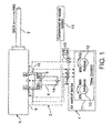
- FIG. 1 is a schematic view showing a drill driving device connected to an air control device according to an example of the present invention.
- An air control device 1 is connected to a drill driving device 3 via air flow passages 2. Dot-dash lines in FIG. 1 denote the air flow passages.
- the drill driving device 3 may be provided as a constituent element of the air control device 1.
- the drill driving device 3 is formed by attaching a grip 4 to be gripped by a user to a tool driver 5.
- the tool driver 5 applies a rotation operation and a feed operation in a tool axis direction to a tool T such as a drill and an end mill while holding the tool T.
- the rotation operation and feed operation applied to the tool T are performed using compressed air as a main power source.
- the tool driver 5 is provided with a first air suction port 6 that supplies air for advancing the tool T advancing air to a pneumatic cylinder and a second air suction port 7 that supplies air for retracting the tool T to the pneumatic cylinder.
- auxiliary constituent components of the tool driver 5 and the drill driving device 3 may be provided with an air suction port required for air control undertaken with other aims, such as supplying cutting oil and controlling of a feed speed of the tool T.
- ON and OFF switches 8 for controlling drill driving is provided in the vicinity of the grip 4 of the tool driver 5.
- the air flow passages are opened and closed by the ON and OFF switches 8.
- the air control device 1 includes air suction ports 9 from which air is taken in, air discharge ports 10 which discharge the taken-in air, and an air control system 11.
- Each of the air discharge ports 10 includes at least a first air discharge port 10A corresponding to an air flow passage 2 of the drill driving device 3 for advancing the tool and a second air discharge port 10B corresponding to another air flow passage 2 of the drill driving device 3 for retracting the tool.
- the first air discharge port 10A and the second air discharge port 10B of the air control device 1 are respectively coupled to the first air suction port 6 and the second air suction port 7 of the drill driving device 3 via the respective air flow passages 2.
- the drill driving device 3 applies feed operations for causing the tool T to advance and retreat in the tool axis direction using air discharged from the air discharge ports 10 of the air control device 1 as power.
- the air control system 11 of the air control device 1 has a function for discharging air from the air discharge ports 10 alternately for respective preset times. More specifically, the air control system 11 discharges air for advancing the tool (hereinafter referred to as “tool advancing air”) and air for retracting the tool (hereinafter referred to as “tool retracting air”)from the first air discharge port 10A and the second air discharge port 10B alternately for respective predetermined durations in accordance with step drilling conditions.
- tools advancing air air for advancing the tool
- tool retracting air air for retracting the tool
- Step drilling is processing for drilling a hole by repeatedly causing the tool T to advance and retreat alternately. By performing step drilling, a deep hole having a favorable inner surface finish can be drilled while ensuring that chips are discharged favorably.
- the air control system 11 may be provided with a time delay valve 12 as a timer for adjusting the times during which the air is discharged from the air discharge ports 10.
- the time delay valve 12 is a device that is caused to apply a delay to a transmission time of an air pressure signal by inputting air into a fixed-capacity container thereof through a variable throttle.
- At least either one of an advancement time and a retreat time of the tool T during step drilling can be adjusted variably using a knob for adjusting the variable throttle of the time delay valve 12.
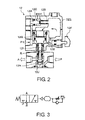
- FIG. 2 is a sectional view showing the details of the structure of the time delay valve 12 shown in FIG. 1
- FIG. 3 is a view showing the time delay valve 12 of FIG. 2 using JIS symbols.
- the width of the gap formed by the needle 12E can be adjusted using a knob 12F. Hence, the flow speed of the air flowing into the tank 12D can also be controlled variably.
- a pressure in the tank 12D increases, a spring 12H and a push rod 12I are pushed together with a piston 12G. As a result, a valve 12J opens, enabling air to flow from an inlet P to an outlet A of the time delay valve 12.
- FIG. 2 shows a condition in which the valve 12J is closed such that the air flows into the tank 12D.
- both a time delay valve 12 for adjusting the advancement time of the tool T and a time delay valve 12 for adjusting the retreat time of the tool T are provided in the air control system 11.
- a knob of the time delay valve 12 for adjusting the advancement time of the tool T is used as a dial for adjusting the advancement time of the tool T, while a knob of the time delay valve 12 for adjusting the retreat time of the tool T is used as a dial for adjusting the retreat time of the tool T.
- the knobs of the time delay valves 12 may be used as dials for adjusting an advancement distance and a retreat distance of the tool T.
- the advancement distance and retreat distance of the tool T may be determined in advance in accordance with the advancement time and retreat time of the tool T and respective flow speeds of the tool advancing air and tool retracting air, whereupon memories of the dials are tuned respectively in accordance with the advancement distance and the retreat distance of the tool T.
- Relationships between the advancement time and retreat time of the tool T and the advancement distance and retreat distance of the tool T can be determined easily by experiment.
- the knobs of the time delay valves 12 can be adjusted using feed amounts as the step drilling conditions.
- the air control system 11 may be configured as desired as far as the air control functions described above are provided.
- An air operated valve, a regulator, and on the like may be used in addition to the time delay valves 12 as relay devices for processing the air pressure signal.
- the air operated valve opens and closes in response to an input of the air pressure signal.
- the regulator is a relay device for adjusting an air pressure of the air pressure signal.
- the air control system 11 is preferably provided with an air speed controller for ensuring that air is introduced into the time delay valves 12 at an appropriate flow speed. By providing the speed controller in the air control system 11, the times can be adjusted more finely.
- the compressed air supplied to the air suction ports 9 of the air control system 11 is supplied from a compressed air supply system 13.
- the compressed air can be supplied to the air control system 11 directly from the compressed air supply system 13, but may also be supplied indirectly.
- the typical pneumatic drill driving device 3 includes a compressed air supply port 14 through which the compressed air is supplied.
- an attachment 15 can be detachably attached to the drill driving device 3, the attachment 15 connecting an output side of the compressed air supply system 13 to the compressed air supply port 14 of the drill driving device 3, so as to take in the compressed air supplied via the compressed air supply port 14 from the drill driving device 3, and then supply the air again to the drill driving device 3.
- the air control device 1 can be connected to the conventional pneumatic drill driving device 3. Further, when step drilling is not performed, the drill driving device 3 can be used without the air control device 1 by detaching the air control device 1 from the drill driving device 3.
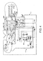
- FIG. 4 is a view showing a specific configuration of the air control device 1 and the drill driving device 3 shown in FIG. 1 .
- FIG. 4 the air relay devices are illustrated using JIS symbols. Furthermore, compressed air flow passages are illustrated using solid lines, and cutting oil flow passages are illustrated using dot-dot-dash lines.
- a cutting oil supply tank 20 is connected to the drill driving device 3 in FIG. 4 as an accessory in addition to the tool driver 5. Further, the tool driver 5 is provided with a hydraulic damper 21 as a device for controlling the feed speed of the tool T.
- Cutting oil is stored in the cutting oil supply tank 20.
- the cutting oil is supplied to the tool driver 5 from the cutting oil supply tank 20 using compressed air supplied from the tool driver 5 as power.
- a compressed air supply port 20A is provided for the cutting oil supply tank 20.
- the air supply port 20A of the cutting oil supply tank 20 is connected to a compressed air discharge port 5A provided for the tool driver 5 via an air flow passage.
- a cutting oil discharge port 20B is provided for the cutting oil supply tank 20.
- the cutting oil discharge port 20B of the cutting oil supply tank 20 is connected to a cutting oil supply port 5B provided for the tool driver 5 via a cutting oil flow passage.
- a compressed air supply port 20C is provided for the cutting oil supply tank 20.
- the compressed air supply port 20C of the cutting oil supply tank 20 is connected to one of compressed air supply ports 21 A provided for the hydraulic damper 21 via an air flow passage. Compressed air discharged from the cutting oil supply tank 20 is used as power air for the hydraulic damper 21.
- the air control system 11 can be formed by connecting the time delay valves 12, an air operated valve 22, a speed controller 23, and a regulator 24 via compressed air flow passages, as shown in the drawing. By connecting the various relay devices in the manner shown in FIG. 4 , the air control system 11 can be made capable of alternately discharging the tool advancing air and the tool retracting air used in the step drilling.
- the air control system 11 is connected to the compressed air supply port 21A of the hydraulic damper 21 via a compressed air flow passage.
- air for locking the hydraulic damper 21 and air for unlocking the hydraulic damper 21 is supplied to the hydraulic damper 21 from the air control system 11.
- a stop switch 5C of the tool driver 5 contacts a contact plate so as to be pressed thereby, and as a result, air is discharged through two discharge ports 5D and 5E.
- the air discharged from the discharge port 5D passes through a check valve so as to be supplied to the tool driver 5 as the tool retracting air.
- the air discharged from the other discharge port 5E is used as operating air for operating the air operated valve 22 of the air control system 11. More specifically, air for controlling the hydraulic damper 21 is supplied to the hydraulic damper 21 from the air control system 11 in response to an opening/closing operation of the air operated valve 22.
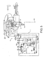
- FIG. 5 is a view showing another specific configuration of the air control device 1 and the drill driving device 3 shown in FIG. 1 .
- the ON and OFF switches 8 are disposed in an upper portion of the tool driver 5. Further, similarly to the drill driving device 3 shown in FIG. 4 , the cutting oil supply tank 20 and the hydraulic damper 21 are provided for the drill driving device 3.
- the drill driving device 3 shown in FIG. 5 is provided with air supply ports and discharge ports identified by numbers 1 to 7.
- the air supply ports and discharge ports of the drill driving device 3 identified by the respective numbers are respectively connected to the corresponding air discharge ports 10, 10A and 10B and the air suction ports 9 of the air control device 1 via the air flow passages 2.
- the air control device 1 can be constructed by disposing the time delay valves 12, the air operated valve 22, the speed controller 23, and the regulator 24 appropriately, as shown in FIG. 5 , .
- the air control device 1 may be constructed in accordance with a pipe configuration of an air control system provided in the drill driving device 3.
- the dials of the time delay valves 12 are tuned in advance in accordance with respective supply times of the tool advancing air and the tool retracting air in accordance with the step drilling conditions. Compressed air is then supplied from the compressed air supply system 13. As a result, air is taken into the air control device 1, whereupon the air control device 1 enters standby. Meanwhile, air is also supplied to the cutting oil supply tank 20 and the hydraulic damper 21 of the drill driving device 3, whereupon the drill driving device 3 enters standby.
- the flow passages in the air control device 1 are varied by opening and closing the time delay valves 12. Accordingly, the tool retracting air is supplied from the second air discharge port 10B of the air control device 1 to the second air suction port 7 of the drill driving device 3. As a result, the tool T is caused to retreat by the tool driver 5.
- the flow passages in the air control device 1 are varied by opening and closing the time delay valves 12. Accordingly, the tool advancing air is supplied from the first air discharge port 10A of the air control device 1 to the first air suction port 6 of the drill driving device 3 again. As a result, the tool T is caused to advance again by the tool driver 5.
- the tool T is repeatedly caused to advance and retreat alternately.
- air is discharged into the drill driving device 3 alternately through the air discharge ports 10 of the air control device 1 for the respectively preset times.
- step drilling the advancement time is set to be longer than the retreat time. Therefore, the position of the tool T gradually approaches the maximum stroke.
- the stop switch 5C of the tool driver 5 contacts the contact plate so as to be pressed thereby.
- the air flow passages in the drill driving device 3 and the air control device 1 are varied such that the drill driving device 3 and the air control device 1 return to their respective initial conditions and then enter standby again.
- the air flow passages in the drill driving device 3 and the air control device 1 are likewise varied such that the drill driving device 3 and the air control device 1 return to their respective initial conditions and then enter standby again.
- the air control device 1 is an air pressure signal control device that outputs suctioned air to the drill driving device 3 along a plurality of paths in a time-divided fashion.
- the air control device 1 also performs air pressure signal control using the time delay valves 12 so that the period in which air is supplied to the drill driving device 3 can be adjusted.
- chips can be favorably discharged to the outside of a hole during drilling work, and therefore chip clogging can be avoided.
- an increase in an operation time due to chip clogging can be avoided, thereby enabling an improvement in drilling efficiency.
- a quality of the hole can be improved. This is particularly effective when drilling a deep hole.
- a user During conventional step drilling, a user must switch the drill driving device 3 ON and OFF manually.
- the air control device 1 By using the air control device 1, on the other hand, a hole can be step-drilled automatically by supplying compressed air that flows in a single direction.
- a step drilling operation can therefore be performed easily. Further, by using the time delay valves 12 as timers, step amounts of the step drilling can be adjusted variably. As a result, step drilling can be performed under conditions corresponding to the hole depth.
- the air control device 1 uses an air pressure signal as a control signal. Hence, an electric system is not required as the power source of the air control device 1, and therefore the air control device 1 can be used on various sites.
Landscapes
- Engineering & Computer Science (AREA)
- Mechanical Engineering (AREA)
- Physics & Mathematics (AREA)
- Fluid Mechanics (AREA)
- General Engineering & Computer Science (AREA)
- Drilling And Boring (AREA)
Abstract
Description
- The present invention relates to air control devices and an air control methods.
- A pneumatic drill driving device is known as a conventional hand tool (see Japanese Unexamined Patent Application Publication
JP-A-2010-228 049 - An object of the present invention is therefore to provide an air control device and an air control method with which a drilled hole can be prevented from becoming clogged with chips.
- An aspect of the present invention provides an air control device including: an air suction port, air discharge ports, and an air control system. The air suction port takes in air. The air discharge ports discharge the taken-in air. The air control system discharges the air through the air discharge ports alternately for respective preset times.
- Another aspect of the present invention provides an air control method including the steps of taking in air, and discharging the air alternately through air discharge ports for respective preset times.
-
- FIG. 1
- is a schematic view showing a drill driving device connected to an air control device according to an example of the present invention is connected;
- FIG. 2
- is a sectional view showing the details of the structure of a time delay valve shown in
FIG. 1 ; - FIG. 3
- is a view showing the time delay valve of
FIG. 2 using Japanese Industrial Standards (JIS) symbols; - FIG. 4
- is a view showing a specific configuration of the air control device and the drill driving device shown in
FIG. 1 ; and - FIG. 5
- is a view showing another specific configuration of the air control device and the drill driving device shown in
FIG. 1 . - An air control device and an air control method according to an example of the present invention will be described below with reference to the attached drawings.
-
FIG. 1 is a schematic view showing a drill driving device connected to an air control device according to an example of the present invention. - An
air control device 1 is connected to adrill driving device 3 viaair flow passages 2. Dot-dash lines inFIG. 1 denote the air flow passages. Thedrill driving device 3 may be provided as a constituent element of theair control device 1. - The
drill driving device 3 is formed by attaching agrip 4 to be gripped by a user to atool driver 5. Thetool driver 5 applies a rotation operation and a feed operation in a tool axis direction to a tool T such as a drill and an end mill while holding the tool T. The rotation operation and feed operation applied to the tool T are performed using compressed air as a main power source. - Hence, the
tool driver 5 is provided with a firstair suction port 6 that supplies air for advancing the tool T advancing air to a pneumatic cylinder and a secondair suction port 7 that supplies air for retracting the tool T to the pneumatic cylinder. - Further, auxiliary constituent components of the
tool driver 5 and thedrill driving device 3 may be provided with an air suction port required for air control undertaken with other aims, such as supplying cutting oil and controlling of a feed speed of the tool T. - ON and OFF switches 8 for controlling drill driving is provided in the vicinity of the
grip 4 of thetool driver 5. InFIG. 1 , the air flow passages are opened and closed by the ON andOFF switches 8. - The
air control device 1 includesair suction ports 9 from which air is taken in,air discharge ports 10 which discharge the taken-in air, and anair control system 11. - Each of the
air discharge ports 10 includes at least a firstair discharge port 10A corresponding to anair flow passage 2 of thedrill driving device 3 for advancing the tool and a secondair discharge port 10B corresponding to anotherair flow passage 2 of thedrill driving device 3 for retracting the tool. The firstair discharge port 10A and the secondair discharge port 10B of theair control device 1 are respectively coupled to the firstair suction port 6 and the secondair suction port 7 of thedrill driving device 3 via the respectiveair flow passages 2. - The
drill driving device 3 applies feed operations for causing the tool T to advance and retreat in the tool axis direction using air discharged from theair discharge ports 10 of theair control device 1 as power. - The
air control system 11 of theair control device 1 has a function for discharging air from theair discharge ports 10 alternately for respective preset times. More specifically, theair control system 11 discharges air for advancing the tool (hereinafter referred to as "tool advancing air") and air for retracting the tool (hereinafter referred to as "tool retracting air")from the firstair discharge port 10A and the secondair discharge port 10B alternately for respective predetermined durations in accordance with step drilling conditions. - Step drilling is processing for drilling a hole by repeatedly causing the tool T to advance and retreat alternately. By performing step drilling, a deep hole having a favorable inner surface finish can be drilled while ensuring that chips are discharged favorably.
- For this purpose, the
air control system 11 may be provided with atime delay valve 12 as a timer for adjusting the times during which the air is discharged from theair discharge ports 10. Thetime delay valve 12 is a device that is caused to apply a delay to a transmission time of an air pressure signal by inputting air into a fixed-capacity container thereof through a variable throttle. - In other words, at least either one of an advancement time and a retreat time of the tool T during step drilling can be adjusted variably using a knob for adjusting the variable throttle of the
time delay valve 12. -
FIG. 2 is a sectional view showing the details of the structure of thetime delay valve 12 shown inFIG. 1 , andFIG. 3 is a view showing thetime delay valve 12 ofFIG. 2 using JIS symbols. - As shown in
FIG. 2 , when compressed air is input into thetime delay valve 12 in the form of an input signal PIL, apiston 12A is pressed by the compressed air. As a result, aspring 12B is compressed, whereby aplug 12C is closed. Accordingly, the compressed air advances at a predetermined flow speed into atank 12D of thetime delay valve 12 through a gap formed by aneedle 12E. - The width of the gap formed by the
needle 12E can be adjusted using aknob 12F. Hence, the flow speed of the air flowing into thetank 12D can also be controlled variably. - When a pressure in the
tank 12D increases, aspring 12H and a push rod 12I are pushed together with apiston 12G. As a result, avalve 12J opens, enabling air to flow from an inlet P to an outlet A of thetime delay valve 12. - Meanwhile, a backflow from the outlet A to the inlet P is prevented by a resistor R. Further, when the input signal PIL is OFF or the pressure in the
tank 12D is high, theplug 12C is opened by thespring 12B. As a result, the air in thetank 12D is discharged from thetime delay valve 12 in the form of an output signal EXH. Note thatFIG. 2 shows a condition in which thevalve 12J is closed such that the air flows into thetank 12D. - In the case where both the advancement time and the retreat time of the tool T are to be adjusted, both a
time delay valve 12 for adjusting the advancement time of the tool T and atime delay valve 12 for adjusting the retreat time of the tool T are provided in theair control system 11. - In
FIG. 1 , a knob of thetime delay valve 12 for adjusting the advancement time of the tool T is used as a dial for adjusting the advancement time of the tool T, while a knob of thetime delay valve 12 for adjusting the retreat time of the tool T is used as a dial for adjusting the retreat time of the tool T. - The knobs of the
time delay valves 12 may be used as dials for adjusting an advancement distance and a retreat distance of the tool T. In this case, the advancement distance and retreat distance of the tool T may be determined in advance in accordance with the advancement time and retreat time of the tool T and respective flow speeds of the tool advancing air and tool retracting air, whereupon memories of the dials are tuned respectively in accordance with the advancement distance and the retreat distance of the tool T. - Relationships between the advancement time and retreat time of the tool T and the advancement distance and retreat distance of the tool T can be determined easily by experiment. In this case, the knobs of the
time delay valves 12 can be adjusted using feed amounts as the step drilling conditions. - The
air control system 11 may be configured as desired as far as the air control functions described above are provided. An air operated valve, a regulator, and on the like may be used in addition to thetime delay valves 12 as relay devices for processing the air pressure signal. The air operated valve opens and closes in response to an input of the air pressure signal. The regulator is a relay device for adjusting an air pressure of the air pressure signal. - The
air control system 11 is preferably provided with an air speed controller for ensuring that air is introduced into thetime delay valves 12 at an appropriate flow speed. By providing the speed controller in theair control system 11, the times can be adjusted more finely. - The compressed air supplied to the
air suction ports 9 of theair control system 11 is supplied from a compressedair supply system 13. The compressed air can be supplied to theair control system 11 directly from the compressedair supply system 13, but may also be supplied indirectly. - As shown in
FIG. 1 , the typical pneumaticdrill driving device 3 includes a compressedair supply port 14 through which the compressed air is supplied. Thus, anattachment 15 can be detachably attached to thedrill driving device 3, theattachment 15 connecting an output side of the compressedair supply system 13 to the compressedair supply port 14 of thedrill driving device 3, so as to take in the compressed air supplied via the compressedair supply port 14 from thedrill driving device 3, and then supply the air again to thedrill driving device 3. - As a result, the
air control device 1 can be connected to the conventional pneumaticdrill driving device 3. Further, when step drilling is not performed, thedrill driving device 3 can be used without theair control device 1 by detaching theair control device 1 from thedrill driving device 3. -
FIG. 4 is a view showing a specific configuration of theair control device 1 and thedrill driving device 3 shown inFIG. 1 . - In
FIG. 4 , the air relay devices are illustrated using JIS symbols. Furthermore, compressed air flow passages are illustrated using solid lines, and cutting oil flow passages are illustrated using dot-dot-dash lines. - A cutting
oil supply tank 20 is connected to thedrill driving device 3 inFIG. 4 as an accessory in addition to thetool driver 5. Further, thetool driver 5 is provided with ahydraulic damper 21 as a device for controlling the feed speed of the tool T. - Cutting oil is stored in the cutting
oil supply tank 20. The cutting oil is supplied to thetool driver 5 from the cuttingoil supply tank 20 using compressed air supplied from thetool driver 5 as power. For this purpose, a compressedair supply port 20A is provided for the cuttingoil supply tank 20. Theair supply port 20A of the cuttingoil supply tank 20 is connected to a compressedair discharge port 5A provided for thetool driver 5 via an air flow passage. - Meanwhile, a cutting
oil discharge port 20B is provided for the cuttingoil supply tank 20. The cuttingoil discharge port 20B of the cuttingoil supply tank 20 is connected to a cuttingoil supply port 5B provided for thetool driver 5 via a cutting oil flow passage. - Further, a compressed air supply port 20C is provided for the cutting
oil supply tank 20. The compressed air supply port 20C of the cuttingoil supply tank 20 is connected to one of compressedair supply ports 21 A provided for thehydraulic damper 21 via an air flow passage. Compressed air discharged from the cuttingoil supply tank 20 is used as power air for thehydraulic damper 21. - The
air control system 11 can be formed by connecting thetime delay valves 12, an air operatedvalve 22, aspeed controller 23, and aregulator 24 via compressed air flow passages, as shown in the drawing. By connecting the various relay devices in the manner shown inFIG. 4 , theair control system 11 can be made capable of alternately discharging the tool advancing air and the tool retracting air used in the step drilling. - In
FIG. 4 , theair control system 11 is connected to the compressedair supply port 21A of thehydraulic damper 21 via a compressed air flow passage. Thus, air for locking thehydraulic damper 21 and air for unlocking thehydraulic damper 21 is supplied to thehydraulic damper 21 from theair control system 11. - When a position of the tool T in a feed direction reaches a maximum stroke, a
stop switch 5C of thetool driver 5 contacts a contact plate so as to be pressed thereby, and as a result, air is discharged through twodischarge ports - The air discharged from the
discharge port 5D passes through a check valve so as to be supplied to thetool driver 5 as the tool retracting air. The air discharged from theother discharge port 5E is used as operating air for operating the air operatedvalve 22 of theair control system 11. More specifically, air for controlling thehydraulic damper 21 is supplied to thehydraulic damper 21 from theair control system 11 in response to an opening/closing operation of the air operatedvalve 22. -
FIG. 5 is a view showing another specific configuration of theair control device 1 and thedrill driving device 3 shown inFIG. 1 . - In the
drill driving device 3 shown inFIG. 5 , the ON and OFF switches 8 are disposed in an upper portion of thetool driver 5. Further, similarly to thedrill driving device 3 shown inFIG. 4 , the cuttingoil supply tank 20 and thehydraulic damper 21 are provided for thedrill driving device 3. - The
drill driving device 3 shown inFIG. 5 is provided with air supply ports and discharge ports identified bynumbers 1 to 7. The air supply ports and discharge ports of thedrill driving device 3 identified by the respective numbers are respectively connected to the correspondingair discharge ports air suction ports 9 of theair control device 1 via theair flow passages 2. - For the
drill driving device 3 thus configured, theair control device 1 can be constructed by disposing thetime delay valves 12, the air operatedvalve 22, thespeed controller 23, and theregulator 24 appropriately, as shown inFIG. 5 , . - As shown in
FIGs. 4 and5 , theair control device 1 may be constructed in accordance with a pipe configuration of an air control system provided in thedrill driving device 3. - Next, operations and actions of the
air control device 1 will be described. - First, the dials of the
time delay valves 12 are tuned in advance in accordance with respective supply times of the tool advancing air and the tool retracting air in accordance with the step drilling conditions. Compressed air is then supplied from the compressedair supply system 13. As a result, air is taken into theair control device 1, whereupon theair control device 1 enters standby. Meanwhile, air is also supplied to the cuttingoil supply tank 20 and thehydraulic damper 21 of thedrill driving device 3, whereupon thedrill driving device 3 enters standby. - Next, when the ON switch is pressed, air flows into a flow passage that is opened by pressing the ON switch. Accordingly, the tool advancing air is supplied from the first
air discharge port 10A of theair control device 1 to the firstair suction port 6 of thedrill driving device 3. Further, operating air is supplied to thehydraulic damper 21. As a result, the tool T is caused to advance by thetool driver 5. - Following the elapse of the advancement time of the tool T, which is set as a step drilling condition, the flow passages in the
air control device 1 are varied by opening and closing thetime delay valves 12. Accordingly, the tool retracting air is supplied from the secondair discharge port 10B of theair control device 1 to the secondair suction port 7 of thedrill driving device 3. As a result, the tool T is caused to retreat by thetool driver 5. - Following the elapse of the retreat time of the tool T, which is set as a step drilling condition, the flow passages in the
air control device 1 are varied by opening and closing thetime delay valves 12. Accordingly, the tool advancing air is supplied from the firstair discharge port 10A of theair control device 1 to the firstair suction port 6 of thedrill driving device 3 again. As a result, the tool T is caused to advance again by thetool driver 5. - By opening and closing the
time delay valves 12 similarly thereafter, the tool T is repeatedly caused to advance and retreat alternately. In other words, air is discharged into thedrill driving device 3 alternately through theair discharge ports 10 of theair control device 1 for the respectively preset times. - In step drilling, the advancement time is set to be longer than the retreat time. Therefore, the position of the tool T gradually approaches the maximum stroke. When the position of the tool T reaches the maximum stroke, the
stop switch 5C of thetool driver 5 contacts the contact plate so as to be pressed thereby. - As a result, the air flow passages in the
drill driving device 3 and theair control device 1 are varied such that thedrill driving device 3 and theair control device 1 return to their respective initial conditions and then enter standby again. - When the
stop switch 8 is pressed by a manual operation, the air flow passages in thedrill driving device 3 and theair control device 1 are likewise varied such that thedrill driving device 3 and theair control device 1 return to their respective initial conditions and then enter standby again. - Hence, with the
air control device 1 described above, a hole can be step-drilled by supplying air intermittently to the handhelddrill driving device 3. In other words, theair control device 1 is an air pressure signal control device that outputs suctioned air to thedrill driving device 3 along a plurality of paths in a time-divided fashion. Theair control device 1 also performs air pressure signal control using thetime delay valves 12 so that the period in which air is supplied to thedrill driving device 3 can be adjusted. - According to the
air control device 1, chips can be favorably discharged to the outside of a hole during drilling work, and therefore chip clogging can be avoided. As a result, an increase in an operation time due to chip clogging can be avoided, thereby enabling an improvement in drilling efficiency. In addition, a quality of the hole can be improved. This is particularly effective when drilling a deep hole. - During conventional step drilling, a user must switch the
drill driving device 3 ON and OFF manually. By using theair control device 1, on the other hand, a hole can be step-drilled automatically by supplying compressed air that flows in a single direction. - A step drilling operation can therefore be performed easily. Further, by using the
time delay valves 12 as timers, step amounts of the step drilling can be adjusted variably. As a result, step drilling can be performed under conditions corresponding to the hole depth. - Moreover, the
air control device 1 uses an air pressure signal as a control signal. Hence, an electric system is not required as the power source of theair control device 1, and therefore theair control device 1 can be used on various sites. -
- 1
- air control device
- 2
- air flow passage
- 3
- drill driving device
- 4
- grip
- 5
- tool driver
- 5A
- air discharge port
- 5B
- oil supply port
- 5C
- stop switch
- 5D
- air discharge port
- 5E
- air discharge port
- 6
- first air suction port
- 7
- second air suction port
- 8
- switches
- 9
- air suction ports
- 10
- air discharge port
- 10A
- first air discharge port
- 10B
- second air discharge port
- 11
- air control system
- 12
- time delay valve
- 12A
- piston
- 12B
- spring
- 12C
- plug
- 12D
- tank
- 12E
- needle
- 12F
- knob
- 12G
- piston
- 12H
- spring
- 12I
- push rod
- 13
- air supply system
- 14
- air supply port
- 15
- attachment
- 20
- cutting oil supply tank
- 20A
- air supply port
- 20B
- cutting oil discharge port
- 20C
- air supply port
- 22
- air operated valve
- 23
- speed controller
- 24
- regulator
- A
- outlet
- P
- inlet
- R
- resistor
- T
- tool
- PIL
- input signal
- EXH
- output signal
Claims (6)
- An air control device comprising:- an air suction port (6, 7) adapted to take in air;- air discharge ports (10) adapted to discharge the taken-in air; and- an air control system (11) adapted to discharge the air through the air discharge ports (10) alternately for respective preset times.
- The air control device according to claim 1,
wherein the air control system (11) is provided with a time delay valve (12) as a timer for adjusting the times. - The air control device according to claim 1 or 2,
wherein the air control system (11) is provided with an air speed controller to ensure that the air is introduced into the time delay valve (12) at an appropriate speed. - The air control device according to any one of claims 1 to 3,
wherein each of the air discharge ports (10) includes- at least a first air discharge port (10A) corresponding to a flow passage (2) for air adapted to advance a tool (T), the flow passage (2) being provided in a drill driving device (3), and- a second air discharge port (10B) corresponding to a flow passage (2) for air adapted to retract the tool (T), the flow passage (2) being provided in the drill driving device (3), andwherein the air control system (11) is adapted to discharge the air to advance the tool (T) and the air to retract the tool (T) alternately in accordance with conditions of a step of drilling operation in which a hole is drilled by repeatedly causing a tool (T) to advance and retreat alternately. - The air control device according to any one of claims 1 to 4,
wherein the drill driving device (3) is adapted to apply feed operations for causing the tool (T) to advance and retreat in a tool axis direction by using the air discharged from the plurality of air discharge ports (10, 10A, 10B) as power. - An air control method comprising:- taking in air; and- discharging the air alternately through air discharge ports (10, 10A, 10B) for respective preset times.
Applications Claiming Priority (1)
| Application Number | Priority Date | Filing Date | Title |
|---|---|---|---|
| JP2012198990A JP6009869B2 (en) | 2012-09-10 | 2012-09-10 | Air control device and air control method |
Publications (2)
| Publication Number | Publication Date |
|---|---|
| EP2705927A1 true EP2705927A1 (en) | 2014-03-12 |
| EP2705927B1 EP2705927B1 (en) | 2017-05-03 |
Family
ID=49165510
Family Applications (1)
| Application Number | Title | Priority Date | Filing Date |
|---|---|---|---|
| EP13182617.4A Active EP2705927B1 (en) | 2012-09-10 | 2013-09-02 | Air control device and air control method |
Country Status (3)
| Country | Link |
|---|---|
| US (1) | US9555482B2 (en) |
| EP (1) | EP2705927B1 (en) |
| JP (1) | JP6009869B2 (en) |
Families Citing this family (4)
| Publication number | Priority date | Publication date | Assignee | Title |
|---|---|---|---|---|
| JP7569608B2 (en) | 2021-01-28 | 2024-10-18 | 株式会社Subaru | Method for manufacturing drill and drilled item |
| JP2024035337A (en) | 2022-09-02 | 2024-03-14 | 株式会社Subaru | Tool drive device and method for manufacturing hole-processed products |
| JP2024035338A (en) | 2022-09-02 | 2024-03-14 | 株式会社Subaru | Tool drive device and method for manufacturing cut products |
| CN115814468B (en) * | 2022-12-08 | 2024-09-13 | 国网重庆市电力公司电力科学研究院 | Transformer oil-paper insulation dewatering device and use method thereof |
Citations (5)
| Publication number | Priority date | Publication date | Assignee | Title |
|---|---|---|---|---|
| US3212372A (en) * | 1962-11-21 | 1965-10-19 | Sheldon Machine Company Inc | Feed and dwell system |
| US3227049A (en) * | 1963-05-27 | 1966-01-04 | Landis Gendron S A | Means for axially reciprocating a revolving shaft |
| US3802792A (en) * | 1972-12-04 | 1974-04-09 | A Quackenbush | Positive feeding structure with programmed spindle speed control |
| US4064585A (en) * | 1975-10-11 | 1977-12-27 | Loos & Schmidt Wilhelm Loos Gmbh | Thread cutting machine |
| US5222844A (en) * | 1987-10-30 | 1993-06-29 | Cooper Industries, Inc. | Air logic circuit for airfeed peck drill |
Family Cites Families (8)
| Publication number | Priority date | Publication date | Assignee | Title |
|---|---|---|---|---|
| JPS5134993B2 (en) * | 1972-03-14 | 1976-09-29 | ||
| US4123188A (en) * | 1977-04-04 | 1978-10-31 | Gardner-Denver Company | Control system for peck drilling tool |
| DE2907913C2 (en) * | 1979-03-01 | 1983-05-19 | Dornier Gmbh, 7990 Friedrichshafen | Pneumatic hand drill |
| JPS61191810U (en) * | 1985-05-20 | 1986-11-29 | ||
| US4752161A (en) * | 1985-12-16 | 1988-06-21 | The Boeing Company | Hand-held drill with self-advancing bit |
| JPH03153902A (en) * | 1989-11-09 | 1991-07-01 | Nakanishi Shika Kikai Seisakusho:Kk | Fluid drive device |
| US7344341B2 (en) * | 2002-11-27 | 2008-03-18 | West Coast Industries, Inc. | Drill |
| JP5389495B2 (en) * | 2009-03-27 | 2014-01-15 | 株式会社スギノマシン | Air driven drill device |
-
2012
- 2012-09-10 JP JP2012198990A patent/JP6009869B2/en active Active
-
2013
- 2013-09-02 EP EP13182617.4A patent/EP2705927B1/en active Active
- 2013-09-06 US US14/020,109 patent/US9555482B2/en active Active
Patent Citations (5)
| Publication number | Priority date | Publication date | Assignee | Title |
|---|---|---|---|---|
| US3212372A (en) * | 1962-11-21 | 1965-10-19 | Sheldon Machine Company Inc | Feed and dwell system |
| US3227049A (en) * | 1963-05-27 | 1966-01-04 | Landis Gendron S A | Means for axially reciprocating a revolving shaft |
| US3802792A (en) * | 1972-12-04 | 1974-04-09 | A Quackenbush | Positive feeding structure with programmed spindle speed control |
| US4064585A (en) * | 1975-10-11 | 1977-12-27 | Loos & Schmidt Wilhelm Loos Gmbh | Thread cutting machine |
| US5222844A (en) * | 1987-10-30 | 1993-06-29 | Cooper Industries, Inc. | Air logic circuit for airfeed peck drill |
Also Published As
| Publication number | Publication date |
|---|---|
| JP6009869B2 (en) | 2016-10-19 |
| US9555482B2 (en) | 2017-01-31 |
| EP2705927B1 (en) | 2017-05-03 |
| JP2014050943A (en) | 2014-03-20 |
| US20140069677A1 (en) | 2014-03-13 |
Similar Documents
| Publication | Publication Date | Title |
|---|---|---|
| EP2705927B1 (en) | Air control device and air control method | |
| US4915013A (en) | Control valve means for pressurized air-operated devices for driving fasteners into workpieces | |
| US4095916A (en) | Timed intermittent air propelled liquid coolant system for machine tools | |
| US20050223886A1 (en) | Hydraulic actuator | |
| CN107405761A (en) | The method of work and hand-held hydraulic tools of hand-held hydraulic tools | |
| EP2655753B1 (en) | Pressure protection valve for hydraulic tool and method of diabling a hydraulic tool | |
| US20050189127A1 (en) | Pneumatic motor trigger actuator | |
| CN215748919U (en) | Manual hydraulic nut breaking and dismounting tool | |
| RU2698149C2 (en) | Machine hydraulic system and machine | |
| JPH0317616B2 (en) | ||
| DE102013207689A1 (en) | Hand tool | |
| CN103459094A (en) | Device and method for rock and concrete machining | |
| JPH0886182A (en) | Hydraulic striker having controllable number of striking andstriking energy | |
| US20070137934A1 (en) | Portable tool lubrication system | |
| SE532118C2 (en) | Device for a screwdriver and screwdriver | |
| US5558000A (en) | High speed and high load cylinder device | |
| WO2014080664A1 (en) | Intermittent air discharge apparatus | |
| DE102011088958A1 (en) | Pneumatic tool device for hand-held power tool e.g. drilling hammer, has switching valves that are provided for switching pressurization of operating elements and designed as rotary valve | |
| KR100477221B1 (en) | Coolant feeding device of machine tool | |
| TWI380863B (en) | A perforating device with an oiling device | |
| DE102011088979A1 (en) | Pneumatic tool device | |
| CN113710369A (en) | High-pressure fluid ejection device | |
| KR200344229Y1 (en) | Cutting oil and air supplying Apparatus for NC machine | |
| EP1799405B1 (en) | Percussion device | |
| US20050109539A1 (en) | Apparatus and methods for thrust sensing valves |
Legal Events
| Date | Code | Title | Description |
|---|---|---|---|
| PUAI | Public reference made under article 153(3) epc to a published international application that has entered the european phase |
Free format text: ORIGINAL CODE: 0009012 |
|
| AK | Designated contracting states |
Kind code of ref document: A1 Designated state(s): AL AT BE BG CH CY CZ DE DK EE ES FI FR GB GR HR HU IE IS IT LI LT LU LV MC MK MT NL NO PL PT RO RS SE SI SK SM TR |
|
| AX | Request for extension of the european patent |
Extension state: BA ME |
|
| 17P | Request for examination filed |
Effective date: 20140910 |
|
| RBV | Designated contracting states (corrected) |
Designated state(s): AL AT BE BG CH CY CZ DE DK EE ES FI FR GB GR HR HU IE IS IT LI LT LU LV MC MK MT NL NO PL PT RO RS SE SI SK SM TR |
|
| RAP1 | Party data changed (applicant data changed or rights of an application transferred) |
Owner name: FUJI JUKOGYO KABUSHIKI KAISHA Owner name: AMUSSIS INC. |
|
| 17Q | First examination report despatched |
Effective date: 20150129 |
|
| GRAP | Despatch of communication of intention to grant a patent |
Free format text: ORIGINAL CODE: EPIDOSNIGR1 |
|
| INTG | Intention to grant announced |
Effective date: 20160707 |
|
| GRAS | Grant fee paid |
Free format text: ORIGINAL CODE: EPIDOSNIGR3 |
|
| GRAJ | Information related to disapproval of communication of intention to grant by the applicant or resumption of examination proceedings by the epo deleted |
Free format text: ORIGINAL CODE: EPIDOSDIGR1 |
|
| GRAL | Information related to payment of fee for publishing/printing deleted |
Free format text: ORIGINAL CODE: EPIDOSDIGR3 |
|
| INTC | Intention to grant announced (deleted) | ||
| RIN1 | Information on inventor provided before grant (corrected) |
Inventor name: MIMORI, TSUNEARI Inventor name: SAITO, MANABU Inventor name: NAKAHATA, TATSUO Inventor name: WATANABE, MASAO |
|
| GRAR | Information related to intention to grant a patent recorded |
Free format text: ORIGINAL CODE: EPIDOSNIGR71 |
|
| GRAA | (expected) grant |
Free format text: ORIGINAL CODE: 0009210 |
|
| AK | Designated contracting states |
Kind code of ref document: B1 Designated state(s): AL AT BE BG CH CY CZ DE DK EE ES FI FR GB GR HR HU IE IS IT LI LT LU LV MC MK MT NL NO PL PT RO RS SE SI SK SM TR |
|
| INTG | Intention to grant announced |
Effective date: 20170328 |
|
| REG | Reference to a national code |
Ref country code: GB Ref legal event code: FG4D |
|
| REG | Reference to a national code |
Ref country code: AT Ref legal event code: REF Ref document number: 889455 Country of ref document: AT Kind code of ref document: T Effective date: 20170515 Ref country code: CH Ref legal event code: EP |
|
| REG | Reference to a national code |
Ref country code: IE Ref legal event code: FG4D |
|
| REG | Reference to a national code |
Ref country code: DE Ref legal event code: R096 Ref document number: 602013020521 Country of ref document: DE |
|
| RAP2 | Party data changed (patent owner data changed or rights of a patent transferred) |
Owner name: SUBARU CORPORATION Owner name: AMUSSIS INC. |
|
| REG | Reference to a national code |
Ref country code: NL Ref legal event code: MP Effective date: 20170503 |
|
| REG | Reference to a national code |
Ref country code: AT Ref legal event code: MK05 Ref document number: 889455 Country of ref document: AT Kind code of ref document: T Effective date: 20170503 |
|
| REG | Reference to a national code |
Ref country code: LT Ref legal event code: MG4D |
|
| REG | Reference to a national code |
Ref country code: FR Ref legal event code: PLFP Year of fee payment: 5 |
|
| PG25 | Lapsed in a contracting state [announced via postgrant information from national office to epo] |
Ref country code: FI Free format text: LAPSE BECAUSE OF FAILURE TO SUBMIT A TRANSLATION OF THE DESCRIPTION OR TO PAY THE FEE WITHIN THE PRESCRIBED TIME-LIMIT Effective date: 20170503 Ref country code: ES Free format text: LAPSE BECAUSE OF FAILURE TO SUBMIT A TRANSLATION OF THE DESCRIPTION OR TO PAY THE FEE WITHIN THE PRESCRIBED TIME-LIMIT Effective date: 20170503 Ref country code: AT Free format text: LAPSE BECAUSE OF FAILURE TO SUBMIT A TRANSLATION OF THE DESCRIPTION OR TO PAY THE FEE WITHIN THE PRESCRIBED TIME-LIMIT Effective date: 20170503 Ref country code: LT Free format text: LAPSE BECAUSE OF FAILURE TO SUBMIT A TRANSLATION OF THE DESCRIPTION OR TO PAY THE FEE WITHIN THE PRESCRIBED TIME-LIMIT Effective date: 20170503 Ref country code: NO Free format text: LAPSE BECAUSE OF FAILURE TO SUBMIT A TRANSLATION OF THE DESCRIPTION OR TO PAY THE FEE WITHIN THE PRESCRIBED TIME-LIMIT Effective date: 20170803 Ref country code: HR Free format text: LAPSE BECAUSE OF FAILURE TO SUBMIT A TRANSLATION OF THE DESCRIPTION OR TO PAY THE FEE WITHIN THE PRESCRIBED TIME-LIMIT Effective date: 20170503 Ref country code: GR Free format text: LAPSE BECAUSE OF FAILURE TO SUBMIT A TRANSLATION OF THE DESCRIPTION OR TO PAY THE FEE WITHIN THE PRESCRIBED TIME-LIMIT Effective date: 20170804 |
|
| PG25 | Lapsed in a contracting state [announced via postgrant information from national office to epo] |
Ref country code: PL Free format text: LAPSE BECAUSE OF FAILURE TO SUBMIT A TRANSLATION OF THE DESCRIPTION OR TO PAY THE FEE WITHIN THE PRESCRIBED TIME-LIMIT Effective date: 20170503 Ref country code: IS Free format text: LAPSE BECAUSE OF FAILURE TO SUBMIT A TRANSLATION OF THE DESCRIPTION OR TO PAY THE FEE WITHIN THE PRESCRIBED TIME-LIMIT Effective date: 20170903 Ref country code: LV Free format text: LAPSE BECAUSE OF FAILURE TO SUBMIT A TRANSLATION OF THE DESCRIPTION OR TO PAY THE FEE WITHIN THE PRESCRIBED TIME-LIMIT Effective date: 20170503 Ref country code: RS Free format text: LAPSE BECAUSE OF FAILURE TO SUBMIT A TRANSLATION OF THE DESCRIPTION OR TO PAY THE FEE WITHIN THE PRESCRIBED TIME-LIMIT Effective date: 20170503 Ref country code: NL Free format text: LAPSE BECAUSE OF FAILURE TO SUBMIT A TRANSLATION OF THE DESCRIPTION OR TO PAY THE FEE WITHIN THE PRESCRIBED TIME-LIMIT Effective date: 20170503 Ref country code: SE Free format text: LAPSE BECAUSE OF FAILURE TO SUBMIT A TRANSLATION OF THE DESCRIPTION OR TO PAY THE FEE WITHIN THE PRESCRIBED TIME-LIMIT Effective date: 20170503 Ref country code: BG Free format text: LAPSE BECAUSE OF FAILURE TO SUBMIT A TRANSLATION OF THE DESCRIPTION OR TO PAY THE FEE WITHIN THE PRESCRIBED TIME-LIMIT Effective date: 20170803 |
|
| PG25 | Lapsed in a contracting state [announced via postgrant information from national office to epo] |
Ref country code: RO Free format text: LAPSE BECAUSE OF FAILURE TO SUBMIT A TRANSLATION OF THE DESCRIPTION OR TO PAY THE FEE WITHIN THE PRESCRIBED TIME-LIMIT Effective date: 20170503 Ref country code: CZ Free format text: LAPSE BECAUSE OF FAILURE TO SUBMIT A TRANSLATION OF THE DESCRIPTION OR TO PAY THE FEE WITHIN THE PRESCRIBED TIME-LIMIT Effective date: 20170503 Ref country code: SK Free format text: LAPSE BECAUSE OF FAILURE TO SUBMIT A TRANSLATION OF THE DESCRIPTION OR TO PAY THE FEE WITHIN THE PRESCRIBED TIME-LIMIT Effective date: 20170503 Ref country code: EE Free format text: LAPSE BECAUSE OF FAILURE TO SUBMIT A TRANSLATION OF THE DESCRIPTION OR TO PAY THE FEE WITHIN THE PRESCRIBED TIME-LIMIT Effective date: 20170503 Ref country code: DK Free format text: LAPSE BECAUSE OF FAILURE TO SUBMIT A TRANSLATION OF THE DESCRIPTION OR TO PAY THE FEE WITHIN THE PRESCRIBED TIME-LIMIT Effective date: 20170503 |
|
| REG | Reference to a national code |
Ref country code: DE Ref legal event code: R097 Ref document number: 602013020521 Country of ref document: DE |
|
| PG25 | Lapsed in a contracting state [announced via postgrant information from national office to epo] |
Ref country code: IT Free format text: LAPSE BECAUSE OF FAILURE TO SUBMIT A TRANSLATION OF THE DESCRIPTION OR TO PAY THE FEE WITHIN THE PRESCRIBED TIME-LIMIT Effective date: 20170503 Ref country code: SM Free format text: LAPSE BECAUSE OF FAILURE TO SUBMIT A TRANSLATION OF THE DESCRIPTION OR TO PAY THE FEE WITHIN THE PRESCRIBED TIME-LIMIT Effective date: 20170503 |
|
| PLBE | No opposition filed within time limit |
Free format text: ORIGINAL CODE: 0009261 |
|
| STAA | Information on the status of an ep patent application or granted ep patent |
Free format text: STATUS: NO OPPOSITION FILED WITHIN TIME LIMIT |
|
| 26N | No opposition filed |
Effective date: 20180206 |
|
| REG | Reference to a national code |
Ref country code: CH Ref legal event code: PL |
|
| GBPC | Gb: european patent ceased through non-payment of renewal fee |
Effective date: 20170902 |
|
| PG25 | Lapsed in a contracting state [announced via postgrant information from national office to epo] |
Ref country code: SI Free format text: LAPSE BECAUSE OF FAILURE TO SUBMIT A TRANSLATION OF THE DESCRIPTION OR TO PAY THE FEE WITHIN THE PRESCRIBED TIME-LIMIT Effective date: 20170503 Ref country code: MC Free format text: LAPSE BECAUSE OF FAILURE TO SUBMIT A TRANSLATION OF THE DESCRIPTION OR TO PAY THE FEE WITHIN THE PRESCRIBED TIME-LIMIT Effective date: 20170503 |
|
| REG | Reference to a national code |
Ref country code: IE Ref legal event code: MM4A |
|
| REG | Reference to a national code |
Ref country code: BE Ref legal event code: MM Effective date: 20170930 |
|
| PG25 | Lapsed in a contracting state [announced via postgrant information from national office to epo] |
Ref country code: LU Free format text: LAPSE BECAUSE OF NON-PAYMENT OF DUE FEES Effective date: 20170902 |
|
| PG25 | Lapsed in a contracting state [announced via postgrant information from national office to epo] |
Ref country code: CH Free format text: LAPSE BECAUSE OF NON-PAYMENT OF DUE FEES Effective date: 20170930 Ref country code: LI Free format text: LAPSE BECAUSE OF NON-PAYMENT OF DUE FEES Effective date: 20170930 Ref country code: GB Free format text: LAPSE BECAUSE OF NON-PAYMENT OF DUE FEES Effective date: 20170902 Ref country code: IE Free format text: LAPSE BECAUSE OF NON-PAYMENT OF DUE FEES Effective date: 20170902 |
|
| PG25 | Lapsed in a contracting state [announced via postgrant information from national office to epo] |
Ref country code: BE Free format text: LAPSE BECAUSE OF NON-PAYMENT OF DUE FEES Effective date: 20170930 |
|
| PG25 | Lapsed in a contracting state [announced via postgrant information from national office to epo] |
Ref country code: MT Free format text: LAPSE BECAUSE OF NON-PAYMENT OF DUE FEES Effective date: 20170902 |
|
| REG | Reference to a national code |
Ref country code: FR Ref legal event code: PLFP Year of fee payment: 6 |
|
| PG25 | Lapsed in a contracting state [announced via postgrant information from national office to epo] |
Ref country code: HU Free format text: LAPSE BECAUSE OF FAILURE TO SUBMIT A TRANSLATION OF THE DESCRIPTION OR TO PAY THE FEE WITHIN THE PRESCRIBED TIME-LIMIT; INVALID AB INITIO Effective date: 20130902 |
|
| PG25 | Lapsed in a contracting state [announced via postgrant information from national office to epo] |
Ref country code: CY Free format text: LAPSE BECAUSE OF NON-PAYMENT OF DUE FEES Effective date: 20170503 |
|
| PG25 | Lapsed in a contracting state [announced via postgrant information from national office to epo] |
Ref country code: MK Free format text: LAPSE BECAUSE OF FAILURE TO SUBMIT A TRANSLATION OF THE DESCRIPTION OR TO PAY THE FEE WITHIN THE PRESCRIBED TIME-LIMIT Effective date: 20170503 |
|
| PG25 | Lapsed in a contracting state [announced via postgrant information from national office to epo] |
Ref country code: TR Free format text: LAPSE BECAUSE OF FAILURE TO SUBMIT A TRANSLATION OF THE DESCRIPTION OR TO PAY THE FEE WITHIN THE PRESCRIBED TIME-LIMIT Effective date: 20170503 |
|
| PG25 | Lapsed in a contracting state [announced via postgrant information from national office to epo] |
Ref country code: PT Free format text: LAPSE BECAUSE OF FAILURE TO SUBMIT A TRANSLATION OF THE DESCRIPTION OR TO PAY THE FEE WITHIN THE PRESCRIBED TIME-LIMIT Effective date: 20170503 |
|
| PG25 | Lapsed in a contracting state [announced via postgrant information from national office to epo] |
Ref country code: AL Free format text: LAPSE BECAUSE OF FAILURE TO SUBMIT A TRANSLATION OF THE DESCRIPTION OR TO PAY THE FEE WITHIN THE PRESCRIBED TIME-LIMIT Effective date: 20170503 |
|
| REG | Reference to a national code |
Ref country code: DE Ref legal event code: R081 Ref document number: 602013020521 Country of ref document: DE Owner name: AMUSSIS INC., UTSUNOMIYA, JP Free format text: FORMER OWNERS: AMUSSIS INC., UTSUNOMIYA, TOCHIGI, JP; FUJI JUKOGYO K.K., TOKYO, JP |
|
| PGFP | Annual fee paid to national office [announced via postgrant information from national office to epo] |
Ref country code: FR Payment date: 20250925 Year of fee payment: 13 |
|
| PGFP | Annual fee paid to national office [announced via postgrant information from national office to epo] |
Ref country code: DE Payment date: 20250930 Year of fee payment: 13 |