EP2704535A1 - Cyclotron - Google Patents
Cyclotron Download PDFInfo
- Publication number
- EP2704535A1 EP2704535A1 EP13020087.6A EP13020087A EP2704535A1 EP 2704535 A1 EP2704535 A1 EP 2704535A1 EP 13020087 A EP13020087 A EP 13020087A EP 2704535 A1 EP2704535 A1 EP 2704535A1
- Authority
- EP
- European Patent Office
- Prior art keywords
- filament
- current
- cyclotron
- ion source
- chimney
- Prior art date
- Legal status (The legal status is an assumption and is not a legal conclusion. Google has not performed a legal analysis and makes no representation as to the accuracy of the status listed.)
- Withdrawn
Links
- 238000005452 bending Methods 0.000 claims description 13
- 229910052751 metal Inorganic materials 0.000 claims description 10
- 239000002184 metal Substances 0.000 claims description 10
- 150000002500 ions Chemical class 0.000 abstract description 54
- 239000001257 hydrogen Substances 0.000 description 17
- 229910052739 hydrogen Inorganic materials 0.000 description 17
- -1 hydrogen ions Chemical class 0.000 description 13
- 238000010586 diagram Methods 0.000 description 9
- UFHFLCQGNIYNRP-UHFFFAOYSA-N Hydrogen Chemical compound [H][H] UFHFLCQGNIYNRP-UHFFFAOYSA-N 0.000 description 8
- 238000000605 extraction Methods 0.000 description 8
- 230000000052 comparative effect Effects 0.000 description 4
- 238000012423 maintenance Methods 0.000 description 4
- 230000015556 catabolic process Effects 0.000 description 3
- 238000006731 degradation reaction Methods 0.000 description 3
- 239000002245 particle Substances 0.000 description 3
- 239000000284 extract Substances 0.000 description 2
- 239000002784 hot electron Substances 0.000 description 2
- 238000010884 ion-beam technique Methods 0.000 description 2
- 238000004519 manufacturing process Methods 0.000 description 2
- 229910052715 tantalum Inorganic materials 0.000 description 2
- GUVRBAGPIYLISA-UHFFFAOYSA-N tantalum atom Chemical compound [Ta] GUVRBAGPIYLISA-UHFFFAOYSA-N 0.000 description 2
- 230000007423 decrease Effects 0.000 description 1
- 238000001514 detection method Methods 0.000 description 1
- 238000006073 displacement reaction Methods 0.000 description 1
- 230000005684 electric field Effects 0.000 description 1
- 239000012212 insulator Substances 0.000 description 1
- 239000000463 material Substances 0.000 description 1
- 238000004544 sputter deposition Methods 0.000 description 1
- 238000002560 therapeutic procedure Methods 0.000 description 1
Images



Classifications
-
- H—ELECTRICITY
- H05—ELECTRIC TECHNIQUES NOT OTHERWISE PROVIDED FOR
- H05H—PLASMA TECHNIQUE; PRODUCTION OF ACCELERATED ELECTRICALLY-CHARGED PARTICLES OR OF NEUTRONS; PRODUCTION OR ACCELERATION OF NEUTRAL MOLECULAR OR ATOMIC BEAMS
- H05H13/00—Magnetic resonance accelerators; Cyclotrons
- H05H13/005—Cyclotrons
-
- H—ELECTRICITY
- H05—ELECTRIC TECHNIQUES NOT OTHERWISE PROVIDED FOR
- H05H—PLASMA TECHNIQUE; PRODUCTION OF ACCELERATED ELECTRICALLY-CHARGED PARTICLES OR OF NEUTRONS; PRODUCTION OR ACCELERATION OF NEUTRAL MOLECULAR OR ATOMIC BEAMS
- H05H7/00—Details of devices of the types covered by groups H05H9/00, H05H11/00, H05H13/00
-
- H—ELECTRICITY
- H05—ELECTRIC TECHNIQUES NOT OTHERWISE PROVIDED FOR
- H05H—PLASMA TECHNIQUE; PRODUCTION OF ACCELERATED ELECTRICALLY-CHARGED PARTICLES OR OF NEUTRONS; PRODUCTION OR ACCELERATION OF NEUTRAL MOLECULAR OR ATOMIC BEAMS
- H05H7/00—Details of devices of the types covered by groups H05H9/00, H05H11/00, H05H13/00
- H05H7/08—Arrangements for injecting particles into orbits
- H05H2007/081—Sources
- H05H2007/082—Ion sources, e.g. ECR, duoplasmatron, PIG, laser sources
Definitions
- the present invention relates to a cyclotron having an internal ion source.
- Japanese Unexamined Patent Application Publication No. 58-209899 discloses a cyclotron that includes an ion source having a filament and accelerates ions generated by the ion source using a magnetic field.
- the ion source of the cyclotron there are an internal ion source disposed inside a hollow yoke and an external ion source disposed outside a yoke.
- the internal ion source of these ion sources there has been a problem in that performance degradation of a filament is fast due to the influence of a strong magnetic field generated by the cyclotron and accordingly frequent filament replacement is required.
- the inventors have found out that deformation occurring in the filament is the cause of the performance degradation. That is, when a current flows through the filament, a strong Lorentz force acts on the filament due to the influence of a strong magnetic field of 1 T [tesla] to 3 T [tesla] generated by the cyclotron.
- the filament is usually designed to have a certain degree of strength, the strength of the filament in use decreases gradually since the filament is in a high temperature state and the filament is thinning due to sputtering by electron. As a result, it has been found out that the deformation of the filament occurs without maintaining the strength against the Lorentz force.
- a cyclotron that accelerates an ion using a magnetic field includes: a hollow yoke; and an ion source that is provided in the yoke and generates an ion.
- the ion source includes a conductive cylindrical body and a filament disposed in the cylindrical body. A current is supplied from a power supply to the filament, and a direction of the current supplied to the filament is changed.
- the direction of the Lorentz force is changed by changing the direction of the current supplied to the filament. Accordingly, compared with a case where the Lorentz force is continuously applied in a fixed direction, it is possible to suppress the deformation of the filament and increase the lifespan of the filament. As a result, since it is possible to reduce the frequency of replacement of the filament, it is possible to significantly reduce the maintenance cost and maintenance effort for the cyclotron.
- the cyclotron according to the embodiment of the present invention may further include a control unit that changes a direction of the current, and the current may be a DC current.
- the direction of the DC current is changed by the control unit. Therefore, compared with a case where the direction of the current is constantly changed using an AC current, it is possible to perform effective current control considering the state of the filament.
- a current may flow in a direction perpendicular to a magnetic field at a distal end of the filament.
- a so-called hot cathode PIG ion source in which a current flows in a direction perpendicular to the magnetic field at the distal end of the filament, is adopted. Therefore, since space can be reduced compared with other ion sources, this is advantageous for miniaturization of the cyclotron.
- the filament may be formed by bending a metal plate.
- a cyclotron having an internal ion source capable of increasing the lifespan of a filament.
- a cyclotron 1 is a circular accelerator that accelerates ions supplied from an ion source 2 using a magnetic field and outputs a charged particle beam.
- ions supplied from the ion source 2 for example, protons, heavy particles (heavy ions), electrons, and the like can be mentioned.
- the cyclotron 1 is used as an accelerator for charged particle beam therapy.
- the ion source 2 is located at the center of the disc-shaped cyclotron 1, and is supported by a columnar support member 3 extending along the central axis C of the cyclotron 1.
- the cyclotron 1 includes an annular coil 4 disposed around the central axis C, an RF cavity 5 disposed in the air core portion of the coil 4, a hollow yoke 7, and a control unit 8.
- the yoke 7 is a disc-shaped hollow block formed of magnetic metal, and the coil 4 and the RF cavity 5 are disposed inside the yoke 7.
- the control unit 8 is an electronic control unit configured to include a central processing unit (CPU), a read only memory (ROM), a random access memory (RAM), and the like.
- the control unit 8 performs overall control of the cyclotron 1.
- the cyclotron 1 accelerates ions supplied from the ion source 2 in space G within the RF cavity 5 by supplying a current to the coil 4 to generate a strong magnetic field (arrow B), and outputs an ion beam.
- the strong magnetic field is a magnetic field of 1 T [tesla] or more, for example. Inside the cyclotron 1, for example, a magnetic field of approximately 1 T to 3 T is formed.
- Figs. 2A, 2B , 3A, and 3B are diagrams for explaining the ion source 2.
- the ion source 2 includes a conductive chimney (cylindrical body) 10, a filament 11 and an anti-cathode 12 disposed in the chimney 10, and an extraction electrode 13 for extracting ions from the chimney 10.
- the chimney 10 is a conductive cylindrical member having a closed upper end.
- the anti-cathode 12 is disposed on the upper end side in the chimney 10.
- a lower end side of the chimney 10 is open, and the filament 11 is disposed by being inserted from the lower end side.
- a slit 10a for extracting hydrogen ions (protons) H + is formed on the side surface of the chimney 10. Hydrogen ions H + extracted from the slit 10a accelerate while traveling along the orbit rotating around the chimney 10. In the chimney 10, a middle portion in which the slit 10a is located is formed in a narrow shape according to the rotation orbit of hydrogen ions H + .
- the shape of the chimney 10 is not limited to that described above.
- the filament 11 is a member for emitting electrons (hot electrons) e into the chimney 10 by generating heat by the flow of a current.
- the filament 11 is a metal plate formed of Ta (tantalum), and is formed by bending a single metal plate.
- the filament 11 is formed by bending a single metal plate in the shape of ⁇ that is open downward.
- a curved portion at the distal end of the filament 11 is called a curved portion 11a.
- the shape of the filament 11 is not limited to that described above.
- the filament 11 may be formed by bending a single metal plate in the shape of U that is open downward.
- the anti-cathode 12 is an electrode for holding an electron e in the chimney 10.
- the anti-cathode 12 is disposed so as to face the filament 11 in a magnetic field direction in the chimney 10, and is fixed to the chimney 10 through an annular insulator (not shown).
- the anti-cathode 12 holds the electron e in the chimney 10 by making the electron e reciprocate in the magnetic field direction between the anti-cathode 12 and the filament 11.
- the extraction electrode 13 is an electrode for extracting the hydrogen ions H + generated in the chimney 10 from the slit 10a.
- the extraction electrode 13 is provided outside the slit 10a, and extracts the hydrogen ions H + when an extraction voltage is applied between the extraction electrode 13 and the chimney 10.
- a power supply 14 for supplying a current to the filament 11 is connected to the ion source 2.
- the power supply 14 is a DC power supply, and supplies a DC current to the filament 11.
- the power supply 14 is controlled by the control unit 8, and changes the direction of the current to the filament 11 in response to a signal from the control unit 8. That is, the power supply 14 is configured to be able to change the direction (arrow I A or arrow I B ) of the DC current to the filament 11.
- the power supply 14 is disposed outside the yoke 7. In addition, a dedicated power supply is provided in the chimney 10.
- a hydrogen tank 15 for introducing hydrogen gas into the chimney 10 is provided outside the ion source 2 (refer to Fig. 3B ).
- the hydrogen tank 15 is disposed outside the yoke 7, and hydrogen gas is introduced into the chimney 10 through the inside of the support member 3.
- Fig. 2A is a diagram for explaining the generation of the electron e in the ion source 2.
- the control unit 8 controls the power supply 14 to supply a current to the filament 11.
- the filament 11 generates heat due to the supply of a current, and emits the electron e (hot electron) from the curved portion 11a or the like.
- Fig. 2B is a diagram for explaining the motion of the electron e in the ion source 2.
- the control unit 8 controls a power supply for the chimney 10 to apply a voltage (arc voltage) between the chimney 10 and the filament 11. Accordingly, the electron e emitted from the filament 11 can be extracted to the chimney 10.
- a strong magnetic field generated by the coil 4 is present inside and outside the ion source 2, the electron e is trapped in the magnetic field and moves while accelerating in the magnetic field direction (direction of arrow B).
- Fig. 3A is a diagram for explaining the collision of the electron e in the ion source 2.
- a new electron e is generated from the anti-cathode 12 due to the electron e moving in the direction of arrow B and colliding with the anti-cathode 12.
- the electron e generated from the anti-cathode 12 moves while accelerating in a direction opposite the arrow B along the magnetic field direction. In this manner, the electron e reciprocates between the filament 11 and the anti-cathode 12.
- Fig. 3B is a diagram for explaining the generation of hydrogen ions in the ion source.
- hydrogen gas is introduced from the hydrogen tank 15 into the chimney 10 in a state where the electron e reciprocates within the chimney 10.
- the control unit 8 also controls the introduction of hydrogen gas.
- hydrogen ions H + are generated by collision of the electron e and the hydrogen molecules H 2 , and plasma P in which the hydrogen ions H + and the electron e are mixed is generated.
- the extraction electrode 13 extracts the hydrogen ions H + from the plasma P in the chimney 10 when the extraction voltage is applied thereto.
- the hydrogen ions H + are extracted through the slit 10a, and accelerate while rotating around the chimney 10.
- the cyclotron 1 forms an ion beam by extracting the hydrogen ions H + continuously from the chimney 10 using the extraction electrode 13 and accelerating the hydrogen ions H + using a magnetic field and an electric field.
- Fig. 4 is a perspective view for explaining the Lorentz force F A applied to the filament 11 when a current flows in a direction of arrow I A .
- the Lorentz force F A is applied to the curved portion 11a of the filament 11 due to the influence of a strong magnetic field (for example, a magnetic field of 1 T or more). Since the Lorentz force F A is applied to the filament 11 as long as a current flows, deformation occurs gradually in the filament 11.
- Fig. 5A is a side view showing a filament before deformation
- Fig. 5B is a side view showing a filament after deformation.
- the filament 11 is deformed in a direction in which the curved portion 11a at the distal end falls down due to the influence of the Lorentz force F A . For this reason, it is necessary to replace the filament 11 every predetermined period.
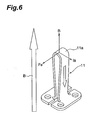
- Fig. 6 is a perspective view for explaining the Lorentz force F B applied to the filament 11 when a current flows in a direction of arrow I B .
- the Lorentz force F A applied to the filament 11 is switched to the Lorentz force F B in the opposite direction by changing the direction of the current from arrow I A to arrow I B by performing polarity switching of the power supply 14 with respect to the filament 11. Then, since the direction of the force applied to the filament 11 is changed, it is possible to suppress the deformation of the filament 11 in one direction.
- the control unit 8 changes the direction of the current to the filament 11 every predetermined time.
- the control unit 8 may change the time interval to change the direction of the current according to the operating conditions of the cyclotron 1 or the like. Conditions under which the control unit 8 changes the direction of the current are not limited to those described above.
- the control unit 8 may change the direction of the current on the basis of the detection state of ions extracted from the chimney 10.
- the direction of the Lorentz force is changed by changing the direction of the current supplied to the filament 11. Accordingly, compared with a case where the Lorentz force is continuously applied in a fixed direction, it is possible to suppress the deformation of the filament 11 and increase the lifespan of the filament 11. As a result, since it is possible to reduce the frequency of replacement of the filament 11, it is possible to significantly reduce the maintenance cost and maintenance effort for the cyclotron 1.
- the DC power supply 14 is adopted, and the direction of the DC current is changed by the control unit 8. Therefore, compared with a case where the direction of the current is constantly changed using an AC current, it is possible to perform effective current control considering the state of the filament 11.
- a so-called hot cathode PIG ion source in which a current flows in a direction perpendicular to the magnetic field on the distal end side of the filament 11, is adopted. Therefore, since space can be reduced compared with other ion sources, this is advantageous for miniaturization of the cyclotron. In addition, since the hot cathode PIG ion source can be stably operated even in a small space, it is possible to increase the reliability of the cyclotron 1.
- the filament 11 is formed by bending one metal plate, and the width direction of the metal plate is made to match a direction in which the Lorentz force is applied. Therefore, it is possible to simplify the configuration of the filament 11 while ensuring the strength against the Lorentz force. This is advantageous in reducing the manufacturing cost of the filament 11.
- the power supply does not need to be a DC power supply, and may be an AC power supply. Since the direction of the current is changed if AC current is used, the direction of the Lorentz force applied to the filament is changed. Accordingly, it is possible to increase the lifespan of the filament.
- the configuration of the ion source is not limited to that described above.
- the shape of the chimney or the filament is not limited to those described above.
- the chimney may have a square tube shape instead of the cylindrical shape, and a narrow portion does not necessarily need to be provided in the middle.
- the filament may be bent in an angular shape.
- Ta tantalum
- a filament with the shape shown in Fig. 4 which had a height of 25 mm, a width of 5 mm, and a thickness of 0.5 mm, was used.
- a DC current supplied to the filament was set to 200 A [ampere], and the magnetic field was set to 1.75 T [tesla] .
- An arc voltage applied between the filament and the chimney was set to 185 V [volt].
- a test was performed for four hours while changing the direction of the current supplied to the filament every hour in a state in which the cyclotron was operating. Then, the amount of bending (displacement of the apex of the filament) of the filament was measured.
- Fig. 7 is a box plot showing a change in the amount of bending of the filament due to polarity switching.
- the amount of bending of the filament was about 0.2 mm.
- the amount of bending of the filament was about 1 mm.
- the amount of bending in the example was about 1/5 of that in the comparative example.
Landscapes
- Physics & Mathematics (AREA)
- Engineering & Computer Science (AREA)
- Plasma & Fusion (AREA)
- Spectroscopy & Molecular Physics (AREA)
- Particle Accelerators (AREA)
- Radiation-Therapy Devices (AREA)
Abstract
Description
- The present invention relates to a cyclotron having an internal ion source.
- As a technical document regarding a cyclotron in the related art, for example, Japanese Unexamined Patent Application Publication No.
58-209899 58-209899 - Incidentally, as the ion source of the cyclotron, there are an internal ion source disposed inside a hollow yoke and an external ion source disposed outside a yoke. In the case of the internal ion source of these ion sources, there has been a problem in that performance degradation of a filament is fast due to the influence of a strong magnetic field generated by the cyclotron and accordingly frequent filament replacement is required.
- Therefore, it is an object of the present invention to provide a cyclotron having an internal ion source capable of increasing the lifespan of a filament.
- As a result of studies about the performance degradation of the filament, the inventors have found out that deformation occurring in the filament is the cause of the performance degradation. That is, when a current flows through the filament, a strong Lorentz force acts on the filament due to the influence of a strong magnetic field of 1 T [tesla] to 3 T [tesla] generated by the cyclotron. Although the filament is usually designed to have a certain degree of strength, the strength of the filament in use decreases gradually since the filament is in a high temperature state and the filament is thinning due to sputtering by electron. As a result, it has been found out that the deformation of the filament occurs without maintaining the strength against the Lorentz force.
- According to an embodiment of the present invention, a cyclotron that accelerates an ion using a magnetic field includes: a hollow yoke; and an ion source that is provided in the yoke and generates an ion. The ion source includes a conductive cylindrical body and a filament disposed in the cylindrical body. A current is supplied from a power supply to the filament, and a direction of the current supplied to the filament is changed.
- In the cyclotron according to the embodiment of the present invention, even if the Lorentz force is applied to the filament due to the influence of a strong magnetic field, the direction of the Lorentz force is changed by changing the direction of the current supplied to the filament. Accordingly, compared with a case where the Lorentz force is continuously applied in a fixed direction, it is possible to suppress the deformation of the filament and increase the lifespan of the filament. As a result, since it is possible to reduce the frequency of replacement of the filament, it is possible to significantly reduce the maintenance cost and maintenance effort for the cyclotron.
- The cyclotron according to the embodiment of the present invention may further include a control unit that changes a direction of the current, and the current may be a DC current.
- According to this cyclotron, the direction of the DC current is changed by the control unit. Therefore, compared with a case where the direction of the current is constantly changed using an AC current, it is possible to perform effective current control considering the state of the filament.
- In the cyclotron according to the embodiment of the present invention, a current may flow in a direction perpendicular to a magnetic field at a distal end of the filament.
- According to this cyclotron, a so-called hot cathode PIG ion source, in which a current flows in a direction perpendicular to the magnetic field at the distal end of the filament, is adopted. Therefore, since space can be reduced compared with other ion sources, this is advantageous for miniaturization of the cyclotron.
- In the cyclotron according to the embodiment of the present invention, the filament may be formed by bending a metal plate.
- According to this configuration, since the width direction of the metal plate is matched with a direction in which the Lorentz force is applied, it is possible to simplify the configuration of the filament while ensuring the strength against the Lorentz force. This is advantageous in reducing the manufacturing cost of the filament.
- According to the present invention, it is possible to provide a cyclotron having an internal ion source capable of increasing the lifespan of a filament.
-
-
Fig. 1 is a cross-sectional view showing a cyclotron according to an embodiment of the present invention. -
Fig. 2A is a diagram for explaining the generation of electrons in the ion source. -
Fig. 2B is a diagram for explaining the motion of electrons in the ion source. -
Fig. 3A is a diagram for explaining the collision of electrons in the ion source. -
Fig. 3B is a diagram for explaining the generation of hydrogen ions in the ion source. -
Fig. 4 is a perspective view for explaining the Lorentz force FA applied to a filament when a current flows in a direction of arrow IA. -
Fig. 5A is a side view showing a filament before deformation.Fig. 5B is a side view showing a filament after deformation. -
Fig. 6 is a perspective view for explaining the Lorentz force FB applied to a filament when a current flows in a direction of arrow IB. -
Fig. 7 is a box plot showing a change in the amount of bending of a filament due to polarity switching. - Hereinafter, a preferred embodiment of the present invention will be described with reference to the drawings.
- As shown in
Fig. 1 , a cyclotron 1, according to the present embodiment is a circular accelerator that accelerates ions supplied from anion source 2 using a magnetic field and outputs a charged particle beam. As ions supplied from theion source 2, for example, protons, heavy particles (heavy ions), electrons, and the like can be mentioned. For example, the cyclotron 1 is used as an accelerator for charged particle beam therapy. - The
ion source 2 is located at the center of the disc-shaped cyclotron 1, and is supported by acolumnar support member 3 extending along the central axis C of the cyclotron 1. - The cyclotron 1 includes an
annular coil 4 disposed around the central axis C, anRF cavity 5 disposed in the air core portion of thecoil 4, a hollow yoke 7, and acontrol unit 8. The yoke 7 is a disc-shaped hollow block formed of magnetic metal, and thecoil 4 and theRF cavity 5 are disposed inside the yoke 7. - The
control unit 8 is an electronic control unit configured to include a central processing unit (CPU), a read only memory (ROM), a random access memory (RAM), and the like. Thecontrol unit 8 performs overall control of the cyclotron 1. - The cyclotron 1 accelerates ions supplied from the
ion source 2 in space G within theRF cavity 5 by supplying a current to thecoil 4 to generate a strong magnetic field (arrow B), and outputs an ion beam. The strong magnetic field is a magnetic field of 1 T [tesla] or more, for example. Inside the cyclotron 1, for example, a magnetic field of approximately 1 T to 3 T is formed. -
Figs. 2A, 2B ,3A, and 3B are diagrams for explaining theion source 2. First, the configuration of theion source 2 will be described with reference toFig. 2A . As shown inFig. 2 A, theion source 2 includes a conductive chimney (cylindrical body) 10, afilament 11 and an anti-cathode 12 disposed in thechimney 10, and anextraction electrode 13 for extracting ions from thechimney 10. - The
chimney 10 is a conductive cylindrical member having a closed upper end. The anti-cathode 12 is disposed on the upper end side in thechimney 10. A lower end side of thechimney 10 is open, and thefilament 11 is disposed by being inserted from the lower end side. - A
slit 10a for extracting hydrogen ions (protons) H+ is formed on the side surface of thechimney 10. Hydrogen ions H+ extracted from theslit 10a accelerate while traveling along the orbit rotating around thechimney 10. In thechimney 10, a middle portion in which theslit 10a is located is formed in a narrow shape according to the rotation orbit of hydrogen ions H+. In addition, the shape of thechimney 10 is not limited to that described above. - The
filament 11 is a member for emitting electrons (hot electrons) e into thechimney 10 by generating heat by the flow of a current. For example, thefilament 11 is a metal plate formed of Ta (tantalum), and is formed by bending a single metal plate. - Specifically, the
filament 11 is formed by bending a single metal plate in the shape of Ω that is open downward. A curved portion at the distal end of thefilament 11 is called acurved portion 11a. In addition, the shape of thefilament 11 is not limited to that described above. For example, thefilament 11 may be formed by bending a single metal plate in the shape of U that is open downward. - The anti-cathode 12 is an electrode for holding an electron e in the
chimney 10. The anti-cathode 12 is disposed so as to face thefilament 11 in a magnetic field direction in thechimney 10, and is fixed to thechimney 10 through an annular insulator (not shown). The anti-cathode 12 holds the electron e in thechimney 10 by making the electron e reciprocate in the magnetic field direction between the anti-cathode 12 and thefilament 11. - The
extraction electrode 13 is an electrode for extracting the hydrogen ions H+ generated in thechimney 10 from theslit 10a. Theextraction electrode 13 is provided outside theslit 10a, and extracts the hydrogen ions H+ when an extraction voltage is applied between theextraction electrode 13 and thechimney 10. - In addition, a
power supply 14 for supplying a current to thefilament 11 is connected to theion source 2. Thepower supply 14 is a DC power supply, and supplies a DC current to thefilament 11. - The
power supply 14 is controlled by thecontrol unit 8, and changes the direction of the current to thefilament 11 in response to a signal from thecontrol unit 8. That is, thepower supply 14 is configured to be able to change the direction (arrow IA or arrow IB) of the DC current to thefilament 11. Thepower supply 14 is disposed outside the yoke 7. In addition, a dedicated power supply is provided in thechimney 10. - In addition, a
hydrogen tank 15 for introducing hydrogen gas into thechimney 10 is provided outside the ion source 2 (refer toFig. 3B ). Thehydrogen tank 15 is disposed outside the yoke 7, and hydrogen gas is introduced into thechimney 10 through the inside of thesupport member 3. - Next, the generation of ions in the
ion source 2 will be described.Fig. 2A is a diagram for explaining the generation of the electron e in theion source 2. As shown inFig. 2A , in theion source 2, first, thecontrol unit 8 controls thepower supply 14 to supply a current to thefilament 11. Thefilament 11 generates heat due to the supply of a current, and emits the electron e (hot electron) from thecurved portion 11a or the like. -
Fig. 2B is a diagram for explaining the motion of the electron e in theion source 2. Thecontrol unit 8 controls a power supply for thechimney 10 to apply a voltage (arc voltage) between thechimney 10 and thefilament 11. Accordingly, the electron e emitted from thefilament 11 can be extracted to thechimney 10. However, since a strong magnetic field generated by thecoil 4 is present inside and outside theion source 2, the electron e is trapped in the magnetic field and moves while accelerating in the magnetic field direction (direction of arrow B). -
Fig. 3A is a diagram for explaining the collision of the electron e in theion source 2. As shown inFig. 3A , in theion source 2, a new electron e is generated from the anti-cathode 12 due to the electron e moving in the direction of arrow B and colliding with the anti-cathode 12. The electron e generated from the anti-cathode 12 moves while accelerating in a direction opposite the arrow B along the magnetic field direction. In this manner, the electron e reciprocates between thefilament 11 and the anti-cathode 12. -
Fig. 3B is a diagram for explaining the generation of hydrogen ions in the ion source. As shown inFig. 3B , in theion source 2, hydrogen gas is introduced from thehydrogen tank 15 into thechimney 10 in a state where the electron e reciprocates within thechimney 10. Thecontrol unit 8 also controls the introduction of hydrogen gas. Thus, in thechimney 10, hydrogen ions H+ are generated by collision of the electron e and the hydrogen molecules H2, and plasma P in which the hydrogen ions H+ and the electron e are mixed is generated. - The
extraction electrode 13 extracts the hydrogen ions H+ from the plasma P in thechimney 10 when the extraction voltage is applied thereto. The hydrogen ions H+ are extracted through theslit 10a, and accelerate while rotating around thechimney 10. The cyclotron 1 forms an ion beam by extracting the hydrogen ions H+ continuously from thechimney 10 using theextraction electrode 13 and accelerating the hydrogen ions H+ using a magnetic field and an electric field. - Here,
Fig. 4 is a perspective view for explaining the Lorentz force FA applied to thefilament 11 when a current flows in a direction of arrow IA. As shown inFigs. 2A to4 , when a current flows in the direction of arrow IA with respect to thefilament 11, the Lorentz force FA is applied to thecurved portion 11a of thefilament 11 due to the influence of a strong magnetic field (for example, a magnetic field of 1 T or more). Since the Lorentz force FA is applied to thefilament 11 as long as a current flows, deformation occurs gradually in thefilament 11. -
Fig. 5A is a side view showing a filament before deformation, andFig. 5B is a side view showing a filament after deformation. As shown inFigs. 5A and 5B , as operating time increases, thefilament 11 is deformed in a direction in which thecurved portion 11a at the distal end falls down due to the influence of the Lorentz force FA. For this reason, it is necessary to replace thefilament 11 every predetermined period. - Therefore, the
control unit 8 changes the direction of the current in thefilament 11 in order to suppress the deformation.Fig. 6 is a perspective view for explaining the Lorentz force FB applied to thefilament 11 when a current flows in a direction of arrow IB. As shown inFig. 6 , the Lorentz force FA applied to thefilament 11 is switched to the Lorentz force FB in the opposite direction by changing the direction of the current from arrow IA to arrow IB by performing polarity switching of thepower supply 14 with respect to thefilament 11. Then, since the direction of the force applied to thefilament 11 is changed, it is possible to suppress the deformation of thefilament 11 in one direction. - The
control unit 8 changes the direction of the current to thefilament 11 every predetermined time. Thecontrol unit 8 may change the time interval to change the direction of the current according to the operating conditions of the cyclotron 1 or the like. Conditions under which thecontrol unit 8 changes the direction of the current are not limited to those described above. For example, thecontrol unit 8 may change the direction of the current on the basis of the detection state of ions extracted from thechimney 10. - In the cyclotron 1 according to the present embodiment described above, even if the Lorentz force is applied to the
filament 11 due to the influence of a strong magnetic field, the direction of the Lorentz force is changed by changing the direction of the current supplied to thefilament 11. Accordingly, compared with a case where the Lorentz force is continuously applied in a fixed direction, it is possible to suppress the deformation of thefilament 11 and increase the lifespan of thefilament 11. As a result, since it is possible to reduce the frequency of replacement of thefilament 11, it is possible to significantly reduce the maintenance cost and maintenance effort for the cyclotron 1. - In addition, in the cyclotron 1, the
DC power supply 14 is adopted, and the direction of the DC current is changed by thecontrol unit 8. Therefore, compared with a case where the direction of the current is constantly changed using an AC current, it is possible to perform effective current control considering the state of thefilament 11. - In addition, in the cyclotron 1, a so-called hot cathode PIG ion source, in which a current flows in a direction perpendicular to the magnetic field on the distal end side of the
filament 11, is adopted. Therefore, since space can be reduced compared with other ion sources, this is advantageous for miniaturization of the cyclotron. In addition, since the hot cathode PIG ion source can be stably operated even in a small space, it is possible to increase the reliability of the cyclotron 1. - In addition, in the cyclotron 1, the
filament 11 is formed by bending one metal plate, and the width direction of the metal plate is made to match a direction in which the Lorentz force is applied. Therefore, it is possible to simplify the configuration of thefilament 11 while ensuring the strength against the Lorentz force. This is advantageous in reducing the manufacturing cost of thefilament 11. - The present invention is not limited to the embodiment described above. For example, the power supply does not need to be a DC power supply, and may be an AC power supply. Since the direction of the current is changed if AC current is used, the direction of the Lorentz force applied to the filament is changed. Accordingly, it is possible to increase the lifespan of the filament.
- In addition, the configuration of the ion source is not limited to that described above. The shape of the chimney or the filament is not limited to those described above. The chimney may have a square tube shape instead of the cylindrical shape, and a narrow portion does not necessarily need to be provided in the middle. In addition, the filament may be bent in an angular shape.
- Hereinafter, a current direction change (polarity switching) in the cyclotron according to the embodiment of the present invention will be described by way of examples and comparative examples.
- In an example, Ta (tantalum) was adopted as a material of a filament, and a filament with the shape shown in
Fig. 4 , which had a height of 25 mm, a width of 5 mm, and a thickness of 0.5 mm, was used. A DC current supplied to the filament was set to 200 A [ampere], and the magnetic field was set to 1.75 T [tesla] . An arc voltage applied between the filament and the chimney was set to 185 V [volt]. - A test was performed for four hours while changing the direction of the current supplied to the filament every hour in a state in which the cyclotron was operating. Then, the amount of bending (displacement of the apex of the filament) of the filament was measured.
- In a comparative example, for the same filament as in the example, a test was performed for four hours without changing the direction of the current, and the amount of bending was measured.
-
Fig. 7 is a box plot showing a change in the amount of bending of the filament due to polarity switching. As shown inFig. 7 , in the example in which there was polarity switching (current direction change), the amount of bending of the filament was about 0.2 mm. On the other hand, in the comparative example in which there was no polarity switching (current direction change), the amount of bending of the filament was about 1 mm. The amount of bending in the example was about 1/5 of that in the comparative example.
Claims (4)
- A cyclotron that accelerates an ion using a magnetic field, comprising:a hollow yoke; andan ion source that is provided in the yoke and generates an ion,wherein the ion source includes a conductive cylindrical body and a filament disposed in the cylindrical body, anda current is supplied from a power supply to the filament, and a direction of the current supplied to the filament is changed.
- The cyclotron according to claim 1, further comprising:a control unit that changes a direction of the current,wherein the current is a DC current.
- The cyclotron according to claim 2,
wherein a current flows in a direction perpendicular to a magnetic field at a distal end of the filament. - The cyclotron according to claim 2,
wherein the filament is formed by bending a metal plate.
Applications Claiming Priority (1)
| Application Number | Priority Date | Filing Date | Title |
|---|---|---|---|
| JP2012194282A JP5955709B2 (en) | 2012-09-04 | 2012-09-04 | cyclotron |
Publications (1)
| Publication Number | Publication Date |
|---|---|
| EP2704535A1 true EP2704535A1 (en) | 2014-03-05 |
Family
ID=49118281
Family Applications (1)
| Application Number | Title | Priority Date | Filing Date |
|---|---|---|---|
| EP13020087.6A Withdrawn EP2704535A1 (en) | 2012-09-04 | 2013-09-03 | Cyclotron |
Country Status (3)
| Country | Link |
|---|---|
| US (1) | US9041318B2 (en) |
| EP (1) | EP2704535A1 (en) |
| JP (1) | JP5955709B2 (en) |
Cited By (1)
| Publication number | Priority date | Publication date | Assignee | Title |
|---|---|---|---|---|
| CN107360662A (en) * | 2017-07-12 | 2017-11-17 | 合肥中科离子医学技术装备有限公司 | A kind of method for improving medical superconducting cyclotron Bunch current precision controlling |
Families Citing this family (7)
| Publication number | Priority date | Publication date | Assignee | Title |
|---|---|---|---|---|
| JP5955709B2 (en) * | 2012-09-04 | 2016-07-20 | 住友重機械工業株式会社 | cyclotron |
| JP6434051B2 (en) * | 2014-12-08 | 2018-12-05 | 株式会社日立製作所 | Accelerator and particle beam irradiation device |
| JP6768845B2 (en) * | 2017-02-01 | 2020-10-14 | 株式会社日立製作所 | Circular accelerator |
| JP6998777B2 (en) * | 2018-01-25 | 2022-01-18 | 住友重機械工業株式会社 | Ion source device and charged particle beam therapy device |
| JP7352412B2 (en) * | 2019-08-28 | 2023-09-28 | 住友重機械工業株式会社 | cyclotron |
| CN110708855B (en) * | 2019-11-12 | 2024-05-31 | 中国工程物理研究院流体物理研究所 | Position adjustment mechanism and adjustment method of rigid ion source in cyclotron |
| JP7791131B2 (en) * | 2023-04-04 | 2025-12-23 | 株式会社日立ハイテク | Ion sources, accelerators and particle therapy systems |
Citations (2)
| Publication number | Priority date | Publication date | Assignee | Title |
|---|---|---|---|---|
| JPS58209899A (en) | 1982-05-31 | 1983-12-06 | 住友重機械工業株式会社 | Accelerator |
| US20080258653A1 (en) * | 2007-04-17 | 2008-10-23 | Advanced Biomarker Technologies, Llc | Cyclotron having permanent magnets |
Family Cites Families (17)
| Publication number | Priority date | Publication date | Assignee | Title |
|---|---|---|---|---|
| US4076990A (en) * | 1975-10-08 | 1978-02-28 | The Trustees Of The University Of Pennsylvania | Tube target for fusion neutron generator |
| JPS596024B2 (en) * | 1981-06-17 | 1984-02-08 | 株式会社東芝 | Ion source power supply |
| JPS60172200A (en) * | 1984-02-16 | 1985-09-05 | 理化学研究所 | Electromagnet for cyclotron |
| US4641057A (en) * | 1985-01-23 | 1987-02-03 | Board Of Trustees Operating Michigan State University | Superconducting synchrocyclotron |
| JPS636798A (en) * | 1986-06-25 | 1988-01-12 | 株式会社日本製鋼所 | Vertical ion source of cyclotron |
| JPH0289759U (en) * | 1988-12-26 | 1990-07-17 | ||
| JPH11283522A (en) * | 1998-03-30 | 1999-10-15 | Mitsubishi Electric Corp | Cyclotron ion source |
| JP2005251468A (en) * | 2004-03-02 | 2005-09-15 | Seiko Epson Corp | Ion generator and ion implanter |
| WO2007130164A2 (en) * | 2006-01-19 | 2007-11-15 | Massachusetts Institute Of Technology | High-field superconducting synchrocyclotron |
| JP4406936B2 (en) * | 2006-11-29 | 2010-02-03 | 株式会社Ihi | Ion implanter |
| JP5615711B2 (en) * | 2007-10-29 | 2014-10-29 | イオン・ビーム・アプリケーションズ・エス・アー | Circular particle accelerator |
| JP2009205971A (en) | 2008-02-28 | 2009-09-10 | Nissin Electric Co Ltd | Ion irradiation device |
| JP2011238441A (en) * | 2010-05-10 | 2011-11-24 | Shimadzu Corp | Ionizer |
| JP6091999B2 (en) * | 2012-06-01 | 2017-03-08 | 住友重機械工業株式会社 | cyclotron |
| JP5955709B2 (en) * | 2012-09-04 | 2016-07-20 | 住友重機械工業株式会社 | cyclotron |
| JP2014102990A (en) * | 2012-11-20 | 2014-06-05 | Sumitomo Heavy Ind Ltd | Cyclotron |
| JP6138466B2 (en) * | 2012-12-03 | 2017-05-31 | 住友重機械工業株式会社 | cyclotron |
-
2012
- 2012-09-04 JP JP2012194282A patent/JP5955709B2/en active Active
-
2013
- 2013-09-03 EP EP13020087.6A patent/EP2704535A1/en not_active Withdrawn
- 2013-09-04 US US14/017,751 patent/US9041318B2/en not_active Expired - Fee Related
Patent Citations (2)
| Publication number | Priority date | Publication date | Assignee | Title |
|---|---|---|---|---|
| JPS58209899A (en) | 1982-05-31 | 1983-12-06 | 住友重機械工業株式会社 | Accelerator |
| US20080258653A1 (en) * | 2007-04-17 | 2008-10-23 | Advanced Biomarker Technologies, Llc | Cyclotron having permanent magnets |
Non-Patent Citations (3)
| Title |
|---|
| A.K.MITRA ET AL: "Filament Power Supply Improvement of the TRIUMF RF System", 1993 IEEE PARTICLE ACCELERATOR CONFERENCE PROCEEDINGS, 1993, pages 1303 - 1305, XP002717835 * |
| D.J.CLARK: "Ion Sources for Cyclotrons", PROCEEDINGS OF 9TH INTERNATIONAL CONFERENCE ON CYCLOTRONS AND THEIR APPLICATIONS, 1981, pages 231 - 240, XP002717836 * |
| J.BOL ET AL: "High Intensity H- cyclotrons for radioisotope production", 1989 IEEE PARTICLE ACCELERATOR CONFERENCE PROCEEDINGS, 1989, pages 764-766, XP002717834 * |
Cited By (2)
| Publication number | Priority date | Publication date | Assignee | Title |
|---|---|---|---|---|
| CN107360662A (en) * | 2017-07-12 | 2017-11-17 | 合肥中科离子医学技术装备有限公司 | A kind of method for improving medical superconducting cyclotron Bunch current precision controlling |
| CN107360662B (en) * | 2017-07-12 | 2018-04-03 | 合肥中科离子医学技术装备有限公司 | A kind of method for improving medical superconducting cyclotron Bunch current precision controlling |
Also Published As
| Publication number | Publication date |
|---|---|
| JP2014049414A (en) | 2014-03-17 |
| US20140062343A1 (en) | 2014-03-06 |
| US9041318B2 (en) | 2015-05-26 |
| JP5955709B2 (en) | 2016-07-20 |
Similar Documents
| Publication | Publication Date | Title |
|---|---|---|
| US9041318B2 (en) | Cyclotron | |
| US9153405B2 (en) | Ion source device and ion beam generating method | |
| US6768120B2 (en) | Focused electron and ion beam systems | |
| US12324088B2 (en) | Ion source, circular accelerator using same, and particle beam therapy system | |
| AU2025271362A1 (en) | Ion source and neutron generator | |
| US12051560B2 (en) | Ion gun and ion milling machine | |
| JP2006351374A (en) | Ion source | |
| WO2019058511A1 (en) | Ion source device | |
| KR20140032194A (en) | Unit for supplying gas and ion beam source having the unit | |
| WO2020123071A1 (en) | Cylindrical shaped arc chamber for indirectly heated cathode ion source | |
| KR101248126B1 (en) | Ion source | |
| JP2023137423A (en) | Ion source and accelerator | |
| JP5663973B2 (en) | Gas cluster ion beam system | |
| JP2010153096A (en) | Ion gun and ion beam extraction method | |
| JP7791131B2 (en) | Ion sources, accelerators and particle therapy systems | |
| CN119967693A (en) | Accelerators and charged particle beam therapy devices | |
| JPH11283522A (en) | Cyclotron ion source | |
| JP2009179835A (en) | Coaxial vacuum arc deposition source and vacuum deposition equipment | |
| JP2025070409A (en) | Ion source, circular accelerator, and particle therapy system | |
| US10170270B1 (en) | Ion source | |
| CN119852151A (en) | Multi-charge state ion source and multi-charge state ion beam output regulation and control method | |
| Eom et al. | Modification of KOMAC Microwave Ion Source | |
| Einenkel et al. | TEST OF A RADIO-FREQUENCY-DRIVEN MULTICUSP PROTON SOURCE | |
| JP2017183145A (en) | Ion source device |
Legal Events
| Date | Code | Title | Description |
|---|---|---|---|
| AK | Designated contracting states |
Kind code of ref document: A1 Designated state(s): AL AT BE BG CH CY CZ DE DK EE ES FI FR GB GR HR HU IE IS IT LI LT LU LV MC MK MT NL NO PL PT RO RS SE SI SK SM TR |
|
| AX | Request for extension of the european patent |
Extension state: BA ME |
|
| PUAI | Public reference made under article 153(3) epc to a published international application that has entered the european phase |
Free format text: ORIGINAL CODE: 0009012 |
|
| 17P | Request for examination filed |
Effective date: 20140904 |
|
| RBV | Designated contracting states (corrected) |
Designated state(s): AL AT BE BG CH CY CZ DE DK EE ES FI FR GB GR HR HU IE IS IT LI LT LU LV MC MK MT NL NO PL PT RO RS SE SI SK SM TR |
|
| GRAP | Despatch of communication of intention to grant a patent |
Free format text: ORIGINAL CODE: EPIDOSNIGR1 |
|
| RIC1 | Information provided on ipc code assigned before grant |
Ipc: H05H 7/08 20060101AFI20181004BHEP |
|
| INTG | Intention to grant announced |
Effective date: 20181025 |
|
| STAA | Information on the status of an ep patent application or granted ep patent |
Free format text: STATUS: THE APPLICATION IS DEEMED TO BE WITHDRAWN |
|
| 18D | Application deemed to be withdrawn |
Effective date: 20190305 |