EP2704383A1 - Method and device for improving a home network making use of an adaptive guard interval - Google Patents
Method and device for improving a home network making use of an adaptive guard interval Download PDFInfo
- Publication number
- EP2704383A1 EP2704383A1 EP12290336.2A EP12290336A EP2704383A1 EP 2704383 A1 EP2704383 A1 EP 2704383A1 EP 12290336 A EP12290336 A EP 12290336A EP 2704383 A1 EP2704383 A1 EP 2704383A1
- Authority
- EP
- European Patent Office
- Prior art keywords
- guard interval
- receiver
- transmitter
- interval length
- estimator
- Prior art date
- Legal status (The legal status is an assumption and is not a legal conclusion. Google has not performed a legal analysis and makes no representation as to the accuracy of the status listed.)
- Granted
Links
Images




Classifications
-
- H—ELECTRICITY
- H04—ELECTRIC COMMUNICATION TECHNIQUE
- H04L—TRANSMISSION OF DIGITAL INFORMATION, e.g. TELEGRAPHIC COMMUNICATION
- H04L25/00—Baseband systems
- H04L25/02—Details ; arrangements for supplying electrical power along data transmission lines
- H04L25/03—Shaping networks in transmitter or receiver, e.g. adaptive shaping networks
-
- H—ELECTRICITY
- H04—ELECTRIC COMMUNICATION TECHNIQUE
- H04L—TRANSMISSION OF DIGITAL INFORMATION, e.g. TELEGRAPHIC COMMUNICATION
- H04L25/00—Baseband systems
- H04L25/02—Details ; arrangements for supplying electrical power along data transmission lines
- H04L25/03—Shaping networks in transmitter or receiver, e.g. adaptive shaping networks
- H04L25/03006—Arrangements for removing intersymbol interference
- H04L25/03012—Arrangements for removing intersymbol interference operating in the time domain
- H04L25/03019—Arrangements for removing intersymbol interference operating in the time domain adaptive, i.e. capable of adjustment during data reception
-
- H—ELECTRICITY
- H04—ELECTRIC COMMUNICATION TECHNIQUE
- H04L—TRANSMISSION OF DIGITAL INFORMATION, e.g. TELEGRAPHIC COMMUNICATION
- H04L25/00—Baseband systems
- H04L25/02—Details ; arrangements for supplying electrical power along data transmission lines
- H04L25/03—Shaping networks in transmitter or receiver, e.g. adaptive shaping networks
- H04L25/03006—Arrangements for removing intersymbol interference
- H04L25/03178—Arrangements involving sequence estimation techniques
- H04L25/03331—Arrangements for the joint estimation of multiple sequences
-
- H—ELECTRICITY
- H04—ELECTRIC COMMUNICATION TECHNIQUE
- H04L—TRANSMISSION OF DIGITAL INFORMATION, e.g. TELEGRAPHIC COMMUNICATION
- H04L27/00—Modulated-carrier systems
- H04L27/26—Systems using multi-frequency codes
- H04L27/2601—Multicarrier modulation systems
- H04L27/2647—Arrangements specific to the receiver only
-
- H—ELECTRICITY
- H04—ELECTRIC COMMUNICATION TECHNIQUE
- H04L—TRANSMISSION OF DIGITAL INFORMATION, e.g. TELEGRAPHIC COMMUNICATION
- H04L27/00—Modulated-carrier systems
- H04L27/26—Systems using multi-frequency codes
- H04L27/2601—Multicarrier modulation systems
- H04L27/2647—Arrangements specific to the receiver only
- H04L27/2655—Synchronisation arrangements
- H04L27/2666—Acquisition of further OFDM parameters, e.g. bandwidth, subcarrier spacing, or guard interval length
-
- H—ELECTRICITY
- H04—ELECTRIC COMMUNICATION TECHNIQUE
- H04L—TRANSMISSION OF DIGITAL INFORMATION, e.g. TELEGRAPHIC COMMUNICATION
- H04L27/00—Modulated-carrier systems
- H04L27/26—Systems using multi-frequency codes
- H04L27/2601—Multicarrier modulation systems
- H04L27/2647—Arrangements specific to the receiver only
- H04L27/2655—Synchronisation arrangements
- H04L27/2689—Link with other circuits, i.e. special connections between synchronisation arrangements and other circuits for achieving synchronisation
- H04L27/2695—Link with other circuits, i.e. special connections between synchronisation arrangements and other circuits for achieving synchronisation with channel estimation, e.g. determination of delay spread, derivative or peak tracking
Definitions
- the present invention generally relates to the field of methods and devices for improving the throughput, quality, stability and performance of home network infrastructure.
- Residential internet connectivity traditionally consists of single voice-band modem, a Digital Subscriber Line or DSL modem, or a coax-cable modem, connected to a computer in the house.
- DSL modem Digital Subscriber Line
- coax-cable modem a coax-cable modem
- Twisted pair phone wires are usually slightly twisted.
- Electrical power wires typically consist of low category cable that is not twisted at all.
- these existing media are usually sensitive to various kinds of noise.
- usable spectrum of such a home network is limited by the characteristics of the medium and structure of the network.
- Some telecommunication standards such as for example ITU G.hn, specify a single Physical Layer based on fast Fourier transform (FFT) orthogonal frequency-division multiplexing (OFDM) modulation and low-density parity-check code (LDPC) forward error correction (FEC) code.
- FFT fast Fourier transform
- OFDM orthogonal frequency-division multiplexing
- LDPC low-density parity-check code
- FEC forward error correction
- OFDM systems split the transmitted signal into multiple orthogonal sub-carriers, which allows the use of a guard interval (GI) in order to avoid inter symbol interference (ISI) in a multipath network environment such as a home network.
- GI guard interval
- ISI inter symbol interference
- the transmitted signals reach the receiver by two or more electromagnetic paths, for example caused by reflection.
- the receiver receives the transmitted signal as a plurality of signals, each with a specific delay.
- a multipath network environment can exist in wireless networks, but can equally exist in wired media, for example in power line communication in which a plurality of parallel wiring paths are present and impedance mismatches cause signal reflections. These issues also arise in other communication mediums such as for example copper twisted pairs, coax. This could lead to the risk that the delayed signals of a received OFDM symbol would overlap with the signals of the next OFDM symbol.
- the transmitter inserts a GI at the beginning of the OFDM symbol.
- GI In some telecommunication standards, such as for example ITU G.hn, different sizes of GI are available.
- a specific GI length is chosen by the transmitter depending on the transmission modulation and coding scheme to cope with the specific multipath network environment.
- a cyclically extended part of the OFDM generally referred to as a cyclic prefix
- pilot signals which are known symbols that are inserted into the signal at regular intervals and pilot carriers that continuously broadcast a reference signal, allows for time and frequency synchronization and channel estimation at the receiver end.
- the GI length set by the transmitter is chosen to be able to cope with a predetermined multi-path network environment.
- GI length is set so that delayed signals, that were caused by a plurality of electromagnetic paths or channel multi-paths between transmitter and receiver, have a period that is smaller than the period of the GI.
- the characteristics of the multipath network environment might change considerably over time, for example in the case of a home network comprising power wires when devices are switched on or off or are plugged in or out of the power sockets or even during power fluctuations during operation of certain devices.
- the GI length chosen by the transmitter then risks being inadequately set for the current conditions.
- a method of operating an OFDM receiver configured to receive a signal transmitted from an OFDM transmitter by means of at least Nk subcarriers, said receiver and said transmitter being connected to a control system (4) configured to calculate an adapted guard interval length Ng', said method comprises the steps of:
- This way of calculating an adapted guard interval length allows for an improved bit error rate when coping with variations in the channel. This allows to adaptively cope with deteriorating channel conditions with an increased number of multi-paths as well as improving channel conditions with a decreased number of multi-paths.
- said filtering parameter ⁇ is an integer in the range from -(Ng-1) to (Ng-1), optionally in the range from 0 to Ng-1.
- said estimator MSE ( ⁇ ) quantifies said difference by means of a mean square error.
- said other channel estimation is one of said plurality of channel estimations of which the filtering parameter ⁇ is a higher step value of said range of said plurality of values for said plurality of filtering parameters ⁇ with respect to the filtering parameter ⁇ of the current channel estimation.
- said estimator B ⁇ MSE ⁇ + 1 MSE ⁇ .
- said optimal ⁇ is calculated in function of argmax ⁇ ⁇ B ( ⁇ ) ⁇ .
- said adapted guard interval length Ng' is provided by said control system to said receiver and said transmitter.
- said transmitter and said receiver adapts said guard interval length Ng for future transmissions to said adapted guard interval length Ng'.
- an OFDM receiver configured to perform the method according to the first aspect of the invention.
- said receiver comprises said control system.
- an OFDM transmitter configured to perform the method according to the first aspect of the invention.
- said transmitter comprises said control system.
- a computer program product adapted to perform the method according to the first aspect of the invention.
- a computer readable storage device encoding a machine-executable computer program according to the fourth aspect of the invention.
- Fig. 1A and 1B schematically illustrate insertion of the Guard Interval during OFDM baseband generation in the transmitter
- Fig. 2A and 2B schematically illustrates a TDM and FDM pilot signal scheme
- Fig. 3 schematically illustrates a Channel Estimator comprising a windowing function
- Fig. 4 illustrates an adaptive windowing function
- Figure 5 shows the search algorithm for computing the optimal ⁇
- Figure 6 shows the setup of the transmitter and the receiver in order to allow an automated system
- Figure 7 illustrates the B calculation during the search algorithm
- Figure 8 shows the impact on the Bit Error Rate for a TDM and FDM pilot scheme
- Figure 9 shows the impact of the number of multi-paths in the channel and the level of parameter estimation accuracy.
- Figure 1 schematically shows a part of the baseband signal 18 generator of an OFDM transmitter 1.
- the resulting baseband signal is then used to modulate a carrier frequency.
- Binary input data 10 is fed to a subcarrier modulator 12 that maps groups of binary input data onto Into In phase (I) and Quadrature (Q) symbols which can be used to modulate the phase and the amplitude of a plurality of sub-carriers of the OFDM signal.
- These sub-carriers are provided as a plurality of parallel signal channels at predetermined frequencies, typically spaced apart by a predetermined frequency difference in function of the respective bandwidth of the sub-carriers.
- modulation for example Quadrature Phase Shift Keying (QSPK), 16 Quadrature Amplitude Modulation (QAM-16), QAM-64, Differential Quadrature Phase Shift Keying (DQPSK), ..., which each map a plurality of bits in the form of a symbol onto such a sub-carrier.
- QSPK Quadrature Phase Shift Keying
- QAM-16 16 Quadrature Amplitude Modulation
- DQPSK Differential Quadrature Phase Shift Keying
- the subcarrier modulator 12 also takes care of insertion of pilot symbols, which will be explained with respect to Figure 3 .
- Ng determines the length of the GI and as explained above is chosen to be larger than the expected delay spread caused by the multipath network environment to prevent inter-symbol interference.
- a parallel to serial convertor 16 finalizes the generation of the baseband signal 18.
- Nf is about 2000 - 4000 and corresponds to the number of subcarriers being used for transmitting the OFDM signal.
- the enumerators k and n as used above can thus also be referred to as a subcarrier index or subcarrier enumerator.
- the length of the guard interval Ng could also be referred to as the length of the cyclically extended part of the time domain signal in the GI, also referred to as the cyclic prefix.
- Transmitter 1 will insert pilot signals in order to allow reliable channel estimation by the receiver 2 so that for example frequency selective fading or phase changes can be coped with efficiently.
- the second one is based on frequency domain multiplexed (FDM) pilot signals in which the transmitter 1 inserts for every OFDM symbol on a predetermined number of subcarriers a known pilot signal, for example every Np subcarriers as shown in Figure 2B .
- TDM time domain multiplexed
- FDM frequency domain multiplexed
- Np will be chosen to be 16, which means that every 1/16 OFDM symbols comprises a pilot signal on all subcarriers and that every 1/16 subcarriers constantly transmits a pilot signal.
- FIG. 3 schematically shows the operation of a Channel Estimator 20 (CE) comprising a windowing function of the receiver 2.
- CE Channel Estimator 20
- the received pilot signals are reverse modulated.
- an Inverse Fourier Transform is applied at step 24.
- the Inverse Fourier Transform (IFFT) is applied to the X subcarriers of the pilot signals.
- IFFT Inverse Fourier Transform
- TDM pilot signals this means that X is equal to Nk and in the case of FDM pilot signals X is equal to Ng.
- the Channel Estimator 20 applies a windowing function to the resulting time domain signal at step 26 so that the effect of the noise on the extraction of the estimated channel information from the pilot signals P(k) can be reduced.
- the windowed time domain signal is converted to the estimated channel information at step 28 by means of a Fourier transformation (FFT).
- FFT Fourier transformation
- the estimated channel information H e (k) is then used to adjust demodulation of the received OFDM symbols of the current transmission.
- this channel estimation is repeated a plurality of times with a modified window size.
- the window size can be reduced such that it is equal to the guard interval length Ng minus an integer filtering parameter ⁇ , then the negative noise effect on the channel estimation can be reduced leading to a reduction in the BER and of course also leading to an increased throughput if an adapted guard interval length Ng' could be used for future transmissions.
- this filtering parameter ⁇ is an integer in the range from 1 to Ng - 1.
- the search algorithm can be executed by a control system 4 which is connected to the channel estimator 20 of the receiver 2 that receives an OFDM transmission from a transmitter 1 through a multipath channel 3.
- the control system 4 could signal to both the transmitter 1 as the receiver 2 the adapted guard interval length Ng' for use as the guard interval length during future transmissions.
- this adapted guard interval length Ng' will then be used by the transmitter 1 during insertion of the guard interval at step 16 and the receiver 2 during the guard interval removal and channel estimation.
- the filtering parameter ⁇ can additionally an integer in the range from -1 to -(Ng-1).
- still other ranges for the filtering parameter ⁇ can be provided, which not necessarily need to be integer ranges, but could equally be for example a range comprising a plurality of real values.
- the filtering parameter ⁇ is to be selected from a plurality of values in the range from -Ng to Ng, so that it results in a corresponding plurality of non-zero window sizes for performing the repeated channel estimations according to the method of the invention.
- the step in between two consecutive values for the filtering parameter ⁇ in this range must not be 1 as in the examples described above, any other suitable integer or non-integer value could alternatively be chosen as the step between two consecutive values for the filtering parameter ⁇ .
- Eb/N0 signal to noise energy ratio
- Figure 9 shows the BER performance with varying numbers of channel paths L. It further validates the previous results and clarifies the dependence of optimal ⁇ on the number of channel paths L.
- this estimator MSE ( ⁇ ) can be calculated in alternative ways. In general any calculation will enable an suitable estimator MSE ( ⁇ ) it it quantifies the difference between the estimated channel information H e (k) with a window size equal to the guard interval length Ng, and the estimated channel information H e ⁇ k with the non-zero window size equal to the guard interval length Ng minus the filtering parameter ⁇ . It is also clear that any other suitable means square error function then the one displayed in the embodiments described above will enable an alternative embodiment according to the invention.
- ratio ratio B( ⁇ ) MSE ⁇ + 1 MSE ⁇ .
- ratio B( ⁇ ) between an estimator MSE( ⁇ ) for a filtering parameter ⁇ of a current channel estimation and an estimator of another of the plurality of channel estimations.
- calculation of the optimal ⁇ can be performed efficiently if that other channel estimation is one of the plurality of channel estimations of which the filtering parameter ⁇ is a higher step value of the range of the plurality of values for the plurality of filtering parameters ⁇ . This means a higher step value of the range with respect to the filtering parameter ⁇ of the current channel estimation.
- the method according to the invention is equally applicable to any other similar scheme that makes use of a Guard Interval, such as for example block processing schemes, comprising any multicarrier or single carrier scheme with GI.
- top, bottom, over, under, and the like are introduced for descriptive purposes and not necessarily to denote relative positions. It is to be understood that the terms so used are interchangeable under appropriate circumstances and embodiments of the invention are capable of operating according to the present invention in other sequences, or in orientations different from the one(s) described or illustrated above.
Landscapes
- Engineering & Computer Science (AREA)
- Computer Networks & Wireless Communication (AREA)
- Signal Processing (AREA)
- Power Engineering (AREA)
- Mobile Radio Communication Systems (AREA)
Abstract
Description
- The present invention generally relates to the field of methods and devices for improving the throughput, quality, stability and performance of home network infrastructure.
- Residential internet connectivity traditionally consists of single voice-band modem, a Digital Subscriber Line or DSL modem, or a coax-cable modem, connected to a computer in the house. With the arrival of new applications and technologies, such as digital television, on-line gaming and home automation, the Internet access needs to be extended to various types of home devices, such as a set-top box, a game console, a home automation system, plural desktops or laptops, etc. All those home devices are then typically interconnected by means of a home network, which need to be set up and configured. A home network typically accesses the Internet via a home network gateway or residential gateway, which is connected to an access network via a traditional DSL modem or coax-cable modem. The interconnectivity between two devices in the home network itself is based on, typically already existing, in-house media such as twisted pair phone wires, electrical power wires, coax-cables and/or wireless technologies like WiFi.
- Most of the time, the in-house available media typically suffers from a low quality physical layer offering poor immunity for interference in-house. Twisted pair phone wires are usually slightly twisted. Electrical power wires typically consist of low category cable that is not twisted at all. As a result, these existing media are usually sensitive to various kinds of noise. Further also the usable spectrum of such a home network is limited by the characteristics of the medium and structure of the network.
- Some telecommunication standards, such as for example ITU G.hn, specify a single Physical Layer based on fast Fourier transform (FFT) orthogonal frequency-division multiplexing (OFDM) modulation and low-density parity-check code (LDPC) forward error correction (FEC) code. OFDM systems split the transmitted signal into multiple orthogonal sub-carriers, which allows the use of a guard interval (GI) in order to avoid inter symbol interference (ISI) in a multipath network environment such as a home network. In a multipath network environment the transmitted signals reach the receiver by two or more electromagnetic paths, for example caused by reflection. The receiver then receives the transmitted signal as a plurality of signals, each with a specific delay. A multipath network environment can exist in wireless networks, but can equally exist in wired media, for example in power line communication in which a plurality of parallel wiring paths are present and impedance mismatches cause signal reflections. These issues also arise in other communication mediums such as for example copper twisted pairs, coax. This could lead to the risk that the delayed signals of a received OFDM symbol would overlap with the signals of the next OFDM symbol. In order to avoid this risk, the transmitter inserts a GI at the beginning of the OFDM symbol. In some telecommunication standards, such as for example ITU G.hn, different sizes of GI are available. A specific GI length is chosen by the transmitter depending on the transmission modulation and coding scheme to cope with the specific multipath network environment. Usually a cyclically extended part of the OFDM, generally referred to as a cyclic prefix, is inserted into the GI. Furthermore the use of pilot signals, which are known symbols that are inserted into the signal at regular intervals and pilot carriers that continuously broadcast a reference signal, allows for time and frequency synchronization and channel estimation at the receiver end.
- The GI length set by the transmitter is chosen to be able to cope with a predetermined multi-path network environment. GI length is set so that delayed signals, that were caused by a plurality of electromagnetic paths or channel multi-paths between transmitter and receiver, have a period that is smaller than the period of the GI. However in the context of a home network the characteristics of the multipath network environment might change considerably over time, for example in the case of a home network comprising power wires when devices are switched on or off or are plugged in or out of the power sockets or even during power fluctuations during operation of certain devices. The GI length chosen by the transmitter then risks being inadequately set for the current conditions.
- An OFDM system with adaptive guard interval length is known from the publication Zhang Zhao-yang, Lai Li-feng, 2003, "A novel OFDM transmission scheme with length-adaptive Cyclic Prefix", Journal of Zhejiang University SCIENCE. The adapted guard interval is calculated during channel estimation as the double of the RMS delay spread estimation. Although this leads to a system with impact on the GI length at the side of the transmitter leading to an improved throughput, the impact of noise at the side of the receiver is not reduced during the channel estimation process which limits the possibilities to improve the average BER.
- Therefore there exists a need for an improved method and system with adaptive guard interval length that is able to cope with changes in a home network environment more efficiently such that the average BER can be reduced without compromising the risk for inter-symbol interference.
- According to a first aspect of the invention there is provided a method of operating an OFDM receiver configured to receive a signal transmitted from an OFDM transmitter by means of at least Nk subcarriers, said receiver and said transmitter being connected to a control system (4) configured to calculate an adapted guard interval length Ng',
said method comprises the steps of: - said receiver (1) comprising a Channel Estimator extracting the estimated channel information He(k) from the pilot signals P(k) by means of a windowing function;
- Performing said channel estimation with a window size equal to the guard interval length, resulting in said estimated channel information He(k),
- k being a subcarrier index and ranging from 0 to Nk-1 in integer increments,
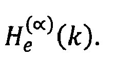
CHARACTERIZED IN THAT, said method further comprises the steps of:- Repeating said channel estimation a plurality of times with a non-zero window size equal to the guard interval length minus a filtering parameter α, said filtering parameter α being in the range from -Ng to Ng, resulting in respective estimated channel information
- for each of said channel estimations:
- calculate an estimator MSE(α) that quantifies the difference between said estimated channel information He(k) with a window size equal to said guard interval length Ng, and said estimated channel information

- calculate a ratio B(∝) between said estimator MSE(α) for said filtering parameter α of the current channel estimation and said estimator of another of said plurality of channel estimations;
- calculate an estimator MSE(α) that quantifies the difference between said estimated channel information He(k) with a window size equal to said guard interval length Ng, and said estimated channel information
- calculate an optimal ∝ in function of said filtering parameter α for which said ratio B(∝) reaches an extremum;
- calculate an adapted guard interval length Ng' = Ng - optimal α.
- Repeating said channel estimation a plurality of times with a non-zero window size equal to the guard interval length minus a filtering parameter α, said filtering parameter α being in the range from -Ng to Ng, resulting in respective estimated channel information
- This way of calculating an adapted guard interval length allows for an improved bit error rate when coping with variations in the channel. This allows to adaptively cope with deteriorating channel conditions with an increased number of multi-paths as well as improving channel conditions with a decreased number of multi-paths.
- According to a specific embodiment said filtering parameter α is an integer in the range from -(Ng-1) to (Ng-1), optionally in the range from 0 to Ng-1.
- This allows for an efficient digital implementation and optionally allows for an efficient calculation with a focus on improving channel conditions, which is especially useful if the initial window size is chosen conservatively.
- According to a further embodiment said estimator MSE(α) quantifies said difference by means of a mean square error.
- In this way a reliable and robust estimator is implemented, which can be calculated efficiently.
- According to an optional embodiment said estimator

- According to a specific embodiment said other channel estimation is one of said plurality of channel estimations of which the filtering parameter α is a higher step value of said range of said plurality of values for said plurality of filtering parameters α with respect to the filtering parameter α of the current channel estimation. Optionally said estimator

- According to a further embodiment said optimal ∝ is calculated in function of argmax∝{B(∝)}.
- According to a further embodiment said adapted guard interval length Ng' is provided by said control system to said receiver and said transmitter.
- Such a setup allows for an automated system.
- According to still a further embodiment said transmitter and said receiver adapts said guard interval length Ng for future transmissions to said adapted guard interval length Ng'.
- In this way an adaptive communication setup is created.
- According to a second aspect of the invention there is provided an OFDM receiver configured to perform the method according to the first aspect of the invention.
- According to an embodiment said receiver comprises said control system.
- This offers that the path from the control system to the receiver that comprises the information needed for its operation is short and the calculations can thus be performed efficiently.
- According to a third aspect of the invention there is provided an OFDM transmitter configured to perform the method according to the first aspect of the invention.
- According to an embodiment said transmitter comprises said control system.
- This offers the advantage that all processing can be done at the transmitter while the receiver only needs to provide the required information. In some of the transmission schemes equalisation is preferred at the transmitter side in order to concentrate processing at this end in order to enable a reduced complexity at the receiver side.
- According to a fourth aspect of the invention there is provided a computer program product adapted to perform the method according to the first aspect of the invention.
- According to a fifth aspect of the invention there is provided a computer readable storage device encoding a machine-executable computer program according to the fourth aspect of the invention.
-
Fig. 1A and 1B schematically illustrate insertion of the Guard Interval during OFDM baseband generation in the transmitter; -
Fig. 2A and 2B schematically illustrates a TDM and FDM pilot signal scheme; -
Fig. 3 schematically illustrates a Channel Estimator comprising a windowing function; -
Fig. 4 illustrates an adaptive windowing function; -
Figure 5 shows the search algorithm for computing the optimal α; -
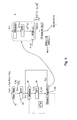
Figure 6 shows the setup of the transmitter and the receiver in order to allow an automated system; -
Figure 7 illustrates the B calculation during the search algorithm; -
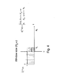
Figure 8 shows the impact on the Bit Error Rate for a TDM and FDM pilot scheme; and -
Figure 9 shows the impact of the number of multi-paths in the channel and the level of parameter estimation accuracy. -
Figure 1 schematically shows a part of the baseband signal 18 generator of anOFDM transmitter 1. The resulting baseband signal is then used to modulate a carrier frequency.Binary input data 10 is fed to asubcarrier modulator 12 that maps groups of binary input data onto Into In phase (I) and Quadrature (Q) symbols which can be used to modulate the phase and the amplitude of a plurality of sub-carriers of the OFDM signal. These sub-carriers are provided as a plurality of parallel signal channels at predetermined frequencies, typically spaced apart by a predetermined frequency difference in function of the respective bandwidth of the sub-carriers. Known examples of modulation are for example Quadrature Phase Shift Keying (QSPK), 16 Quadrature Amplitude Modulation (QAM-16), QAM-64, Differential Quadrature Phase Shift Keying (DQPSK), ..., which each map a plurality of bits in the form of a symbol onto such a sub-carrier. Thesubcarrier modulator 12 also takes care of insertion of pilot symbols, which will be explained with respect toFigure 3 . This creates a modulation data sequence {X(k)}, where k denotes the subcarrier index and with a length of Nk, which is fed to an Inverse Fourier Transformator 14 (IFFT) which transforms the modulation data sequence {X(k)} into a time domain signal {x(n)} with the following equation: x(n) = IDFT{X(k)}, n=0, 1, 2, ..., Nk - 1. Subsequently the GI is inserted, as shown inFigure 1A and 1B , as the cyclically extended part of the OFDM symbol. This means that a predetermined number (Ng) of samples at the end of the time domain signal {x(n)} are added to in front of this signal to create the OFDM symbol xf(n) with the following equation: xf=

serial convertor 16 finalizes the generation of thebaseband signal 18. As shown inFigure 1B in this way theOFDM transmitter 1 generates a sequence of OFDM symbols xf(n) with a period Ts comprising the sequence of Ng samples of the GI during a period Tg and the Nk samples of the sequence of Nf = (Ng + Nk) samples the time domain signal x(n) during a period Tk. In the examples given below the following values will be used for the parameters mentioned below Ng = 16, Nk =256, Nf = Ng + Nk = 16 + 256 = 272. It is clear that other suitable values could be chosen and that typically Nf is about 2000 - 4000 and corresponds to the number of subcarriers being used for transmitting the OFDM signal. It is clear that the enumerators k and n as used above can thus also be referred to as a subcarrier index or subcarrier enumerator. It is further clear that the length of the guard interval Ng could also be referred to as the length of the cyclically extended part of the time domain signal in the GI, also referred to as the cyclic prefix. -
Transmitter 1 will insert pilot signals in order to allow reliable channel estimation by thereceiver 2 so that for example frequency selective fading or phase changes can be coped with efficiently. There are two main types of Channel Estimation know. The first one is based on time domain multiplexed (TDM) pilot signals in which thetransmitter 1 inserts at regular intervals, every Np OFDM symbols, a known Pilot signal on all the subcarriers as shown inFigure 2A . The second one is based on frequency domain multiplexed (FDM) pilot signals in which thetransmitter 1 inserts for every OFDM symbol on a predetermined number of subcarriers a known pilot signal, for example every Np subcarriers as shown inFigure 2B . Typically a suitable combination of TDM and FDM pilot signals are used by thetransmitter 1. For the purpose of example in this description Np will be chosen to be 16, which means that every 1/16 OFDM symbols comprises a pilot signal on all subcarriers and that every 1/16 subcarriers constantly transmits a pilot signal. - The
receiver 2 will receive the signal sent by thetransmitter 1 and demodulate it from the carrier frequency in order to produce an OFDM baseband signal from which the OFDM symbols can be extracted as ys (n) = xf (n) ⊗h(n) + n(n), with n = -Ng, -Ng+1, ... , -1, 0, 1, ..., Nk -1, and where h(n) is the channel impulse response of thechannel 3 between thetransmitter 1 and thereceiver 2 and n(n) is the noise added to signal during transmission in thechannel 3. The receiver will remove the GI from the baseband signal in order to produce a received time domain signal y(n) = yf (n + Ng), n = 0,1,..., Nk - 1 subsequently the received time domain signal y(n) is sent to a Fourier Transformator in order to produce a received modulation data sequence Y(k)= FFT(y(n)), k = 0, 1, ..., Nk-1, with a length of Nk. Assuming there is no ICI or ISI the received modulation data Y(k) = X(k)H(k)+N(k), where H(k) = FFT(h(n)) and N(k)=FFT(n(n)). After this operation thereceiver 2 will extract the pilot signals Ye(k) = P(k). He(k)+N(k) and provide them to a Channel Estimator in order to determine the estimated channel information He(k) = Ye(k) / P(k). As the transmitted pilot signal P(k) is known He(k) can be easily determined from Ye(k). The estimated channel information He(k) is then used to adjust demodulation of the received OFDM symbols. -
Figure 3 schematically shows the operation of a Channel Estimator 20 (CE) comprising a windowing function of thereceiver 2. As explained above in order to determine the estimated channel information He(k) in afirst step 22 the received pilot signals are reverse modulated. Subsequently an Inverse Fourier Transform is applied atstep 24. The Inverse Fourier Transform (IFFT) is applied to the X subcarriers of the pilot signals. In the case of TDM pilot signals this means that X is equal to Nk and in the case of FDM pilot signals X is equal to Ng. Subsequently theChannel Estimator 20 applies a windowing function to the resulting time domain signal atstep 26 so that the effect of the noise on the extraction of the estimated channel information from the pilot signals P(k) can be reduced. Subsequently the windowed time domain signal is converted to the estimated channel information atstep 28 by means of a Fourier transformation (FFT). As explained above the estimated channel information He(k) is then used to adjust demodulation of the received OFDM symbols of the current transmission. - According to the invention however after performing this channel estimation with a window size equal to the guard interval length Ng, resulting in said estimated channel information He(k) this channel estimation is repeated a plurality of times with a modified window size. As shown in
Figure 4 if the window size can be reduced such that it is equal to the guard interval length Ng minus an integer filtering parameter α, then the negative noise effect on the channel estimation can be reduced leading to a reduction in the BER and of course also leading to an increased throughput if an adapted guard interval length Ng' could be used for future transmissions. In order to enable such a reduction this filtering parameter α is an integer in the range from 1 to Ng - 1. For each of these filtering parameter α values a respective estimated channel information
Figures 5 during an additionaliterative step 30 comprising a search algorithm. Subsequently for each of said channel estimations this search algorithm calculates an estimator

- As schematically shown in
Figure 6 the search algorithm can be executed by acontrol system 4 which is connected to thechannel estimator 20 of thereceiver 2 that receives an OFDM transmission from atransmitter 1 through amultipath channel 3. After determining the optimal ∝ from applying the search algorithm on the current transmission thecontrol system 4 could signal to both thetransmitter 1 as thereceiver 2 the adapted guard interval length Ng' for use as the guard interval length during future transmissions. During the next transmission cycle this adapted guard interval length Ng' will then be used by thetransmitter 1 during insertion of the guard interval atstep 16 and thereceiver 2 during the guard interval removal and channel estimation. In this way it is possible to cope with varying channel conditions in an improved and efficient way that will not only allow an improvement in throughput of about 5%-6%, but also an improved BER because of a better rejection of noise during channel estimation as the size of the windowing function is better adapted to the number of multi-paths in the channel. - In order to also cope with a channel changes that deteriorate the channel multi-path situation and require an increase in the guard interval length the filtering parameter α can additionally an integer in the range from -1 to -(Ng-1).
- According to still further alternative embodiments still other ranges for the filtering parameter α can be provided, which not necessarily need to be integer ranges, but could equally be for example a range comprising a plurality of real values. In general the filtering parameter α is to be selected from a plurality of values in the range from -Ng to Ng, so that it results in a corresponding plurality of non-zero window sizes for performing the repeated channel estimations according to the method of the invention. It is further clear that also the step in between two consecutive values for the filtering parameter α in this range must not be 1 as in the examples described above, any other suitable integer or non-integer value could alternatively be chosen as the step between two consecutive values for the filtering parameter α.
-
Figure 7 illustrates the calculation of the ratio
- The BER performance using the method according to the invention with both FDM-pilot and TDM-pilot are illustrated in
Figure 8 . It can be seen that the BER performance is improved until α-lower bound. The lower bound of BER is obtained for an α that equals the number of multi-paths. However in order to cope with accumulation of errors in the calculations due to channel noise optimal ∝ could alternatively be reduced by multiplication with a certain percentage. In that case optimal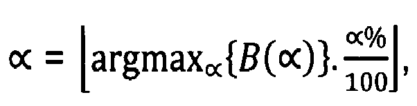
-
Figure 9 shows the BER performance with varying numbers of channel paths L. It further validates the previous results and clarifies the dependence of optimal α on the number of channel paths L. - Although in the embodiments above the estimator MSE(α) has been calculated as

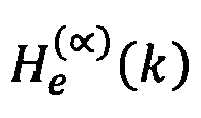
- It is also not required to calculate the ratio ratio B(∝) as in the example above as ratio

- According to still further embodiments it is also not required to calculate optimal ∝ in function of argmax∝{B(∝)} as in general it will suffice to calculate an optimal ∝ in function of a filtering parameter α for which the ratio B(∝) reaches an extremum, which, depending on the ration used could be for example a maximum or minimum of this ratio B(∝).
- Although the embodiments described above refer to an OFDM communication scheme, the method according to the invention is equally applicable to any other similar scheme that makes use of a Guard Interval, such as for example block processing schemes, comprising any multicarrier or single carrier scheme with GI.
- Although the present invention has been illustrated by reference to specific embodiments, it will be apparent to those skilled in the art that the invention is not limited to the details of the foregoing illustrative embodiments, and that the present invention may be embodied with various changes and modifications without departing from the scope thereof. The present embodiments are therefore to be considered in all respects as illustrative and not restrictive, the scope of the invention being indicated by the appended claims rather than by the foregoing description, and all changes which come within the meaning and range of equivalency of the claims are therefore intended to be embraced therein. In other words, it is contemplated to cover any and all modifications, variations or equivalents that fall within the scope of the basic underlying principles and whose essential attributes are claimed in this patent application. It will furthermore be understood by the reader of this patent application that the words "comprising" or "comprise" do not exclude other elements or steps, that the words "a" or "an" do not exclude a plurality, and that a single element, such as a computer system, a processor, or another integrated unit may fulfil the functions of several means recited in the claims. Any reference signs in the claims shall not be construed as limiting the respective claims concerned. The terms "first", "second", third", "a", "b", "c", and the like, when used in the description or in the claims are introduced to distinguish between similar elements or steps and are not necessarily describing a sequential or chronological order. Similarly, the terms "top", "bottom", "over", "under", and the like are introduced for descriptive purposes and not necessarily to denote relative positions. It is to be understood that the terms so used are interchangeable under appropriate circumstances and embodiments of the invention are capable of operating according to the present invention in other sequences, or in orientations different from the one(s) described or illustrated above.
Claims (15)
- A method of operating an OFDM receiver (2) configured to receive a signal transmitted from an OFDM transmitter (1) by means of at least Nk subcarriers, said receiver (2) and said transmitter (1) being connected to a control system (4) configured to calculate an adapted guard interval length Ng',
said method comprises the steps of:- said receiver (1) comprising a Channel Estimator extracting the estimated channel information He(k) from the pilot signals P(k) by means of a windowing function;- Performing said channel estimation with a window size equal to the guard interval length Ng, resulting in said estimated channel information He(k),- k being a subcarrier index and ranging from 0 to Nk-1 in integer increments, CHARACTERIZED IN THAT, said method further comprises the steps of- Repeating said channel estimation a plurality of times with a non-zero window size equal to the guard interval length Ng minus a filtering parameter α, said filtering parameter α being selected from a corresponding plurality of values in the range from -Ng to Ng, resulting in respective estimated channel information - for each of said plurality of channel estimations:○ calculate an estimator MSE(α) that quantifies the difference between said estimated channel information He(k) with a window size equal to said guard interval length Ng, and said estimated channel information
 ○ calculate a ratio B(∝) between said estimator MSE(α) for said filtering parameter α of the current channel estimation and said estimator of another of said plurality of channel estimations;- calculate an optimal ∝ in function of said filtering parameter α for which said ratio B(∝) reaches an extremum;- calculate an adapted guard interval length Ng' = Ng - optimal α.
 - A method according to claim 1, characterised in that said filtering parameter α is an integer in the range from -(Ng-1) to (Ng-1), optionally in the range from 0 to Ng-1.
- A method according to claim 1 or 2, characterised in that said estimator MSE(α) quantifies said difference by means of a mean square error calculation.
- A method according to claim 3, characterised in that said estimator

- A method according to any of the preceding claims, characterised in that said other channel estimation is one of said plurality of channel estimations of which the filtering parameter α is a higher step value of said range of said plurality of values for said plurality of filtering parameters α with respect to the filtering parameter α of the current channel estimation.
- A method according to claim 5, characterised in that said estimator


- A method according to any of the preceding claims, characterised in that said optimal ∝ is calculated in function of argmax∝(B(∝))
- A method according to any of the preceding claims, wherein said adapted guard interval length Ng' is provided by said control system (4) to said transmitter (1) and said receiver (2).
- A method according to claim 8, characterised in that said transmitter (1) and said receiver (2) adapts said guard interval length Ng for future transmissions to said adapted guard interval length Ng'.
- An OFDM receiver (2) configured to perform the method according to claim any of the claims 1 to 9.
- A receiver according to claim 10, characterised in that said receiver (2) comprises said control system (4).
- An OFDM transmitter (1) configured to perform the method according to any of the claims 1 to 9.
- A transmitter according to claim 12, characterised in that said transmitter (1) comprises said control system (4).
- A computer program product adapted to perform the method according to any of the claims 1 to 9.
- A computer readable storage device encoding a machine-executable computer program according to claim 14.
Priority Applications (2)
| Application Number | Priority Date | Filing Date | Title |
|---|---|---|---|
| EP12290336.2A EP2704383B1 (en) | 2012-09-04 | 2012-10-09 | Method and device for improving a home network making use of an adaptive guard interval |
| PCT/EP2013/068132 WO2014037321A1 (en) | 2012-09-04 | 2013-09-03 | Method and device for improving a home network making use of an adaptive guard interval |
Applications Claiming Priority (2)
| Application Number | Priority Date | Filing Date | Title |
|---|---|---|---|
| EP12290290 | 2012-09-04 | ||
| EP12290336.2A EP2704383B1 (en) | 2012-09-04 | 2012-10-09 | Method and device for improving a home network making use of an adaptive guard interval |
Publications (2)
| Publication Number | Publication Date |
|---|---|
| EP2704383A1 true EP2704383A1 (en) | 2014-03-05 |
| EP2704383B1 EP2704383B1 (en) | 2019-05-29 |
Family
ID=46851901
Family Applications (1)
| Application Number | Title | Priority Date | Filing Date |
|---|---|---|---|
| EP12290336.2A Active EP2704383B1 (en) | 2012-09-04 | 2012-10-09 | Method and device for improving a home network making use of an adaptive guard interval |
Country Status (2)
| Country | Link |
|---|---|
| EP (1) | EP2704383B1 (en) |
| WO (1) | WO2014037321A1 (en) |
Families Citing this family (2)
| Publication number | Priority date | Publication date | Assignee | Title |
|---|---|---|---|---|
| US10524161B2 (en) | 2014-08-20 | 2019-12-31 | Qualcomm Incorporated | Delay spread estimation and utilization |
| CN108282422A (en) * | 2017-01-06 | 2018-07-13 | 中兴通讯股份有限公司 | A kind of orthogonal frequency division multiplexing (OFDM) system channel estimation method and terminal |
Citations (1)
| Publication number | Priority date | Publication date | Assignee | Title |
|---|---|---|---|---|
| EP1531593A2 (en) * | 2003-11-11 | 2005-05-18 | NTT DoCoMo, Inc. | OFDM transmitter and OFDM receiver |
-
2012
- 2012-10-09 EP EP12290336.2A patent/EP2704383B1/en active Active
-
2013
- 2013-09-03 WO PCT/EP2013/068132 patent/WO2014037321A1/en not_active Ceased
Patent Citations (1)
| Publication number | Priority date | Publication date | Assignee | Title |
|---|---|---|---|---|
| EP1531593A2 (en) * | 2003-11-11 | 2005-05-18 | NTT DoCoMo, Inc. | OFDM transmitter and OFDM receiver |
Non-Patent Citations (6)
| Title |
|---|
| DONG-HYUN KANG ET AL: "A practical noise mitigation scheme for DVB-T/H system using delay spread estimation", IEEE TRANSACTIONS ON CONSUMER ELECTRONICS, IEEE SERVICE CENTER, NEW YORK, NY, US, vol. 53, no. 1, 5 January 2010 (2010-01-05), pages 9 - 17, XP011306106, ISSN: 0098-3063 * |
| HARIS GACANIN: "Joint iterative channel estimation and guard interval selection for adaptive powerline communication systems", POWER LINE COMMUNICATIONS AND ITS APPLICATIONS (ISPLC), 2013 17TH IEEE INTERNATIONAL SYMPOSIUM ON, IEEE, 24 March 2013 (2013-03-24), pages 197 - 202, XP032420391, ISBN: 978-1-4673-6014-2, DOI: 10.1109/ISPLC.2013.6525849 * |
| NGUYEN-DUC QUANG ET AL: "An Optimal Algorithm of Estimation Channel Combining Kalman Filter with Adaptive Guard Interval for Mobile WiMAX Standard", COMPUTING AND COMMUNICATION TECHNOLOGIES, RESEARCH, INNOVATION, AND VISION FOR THE FUTURE (RIVF), 2012 IEEE RIVF INTERNATIONAL CONFERENCE ON, IEEE, 27 February 2012 (2012-02-27), pages 1 - 4, XP032138223, ISBN: 978-1-4673-0307-1, DOI: 10.1109/RIVF.2012.6169848 * |
| RAMADAN ALI A ET AL: "Adaptive guard interval length for OFDM-based WLAN systems in frequency selective channels", WIRELESS TECHNOLOGY, 2008. EUWIT 2008. EUROPEAN CONFERENCE ON, IEEE, PISCATAWAY, NJ, USA, 27 October 2008 (2008-10-27), pages 115 - 118, XP031408487, ISBN: 978-2-87487-008-8 * |
| SHIGANG TANG ET AL: "Channel estimation for cyclic postfixed OFDM", COMMUNICATIONS, CIRCUITS AND SYSTEMS, 2008. ICCCAS 2008. INTERNATIONAL CONFERENCE ON, IEEE, PISCATAWAY, NJ, USA, 25 May 2008 (2008-05-25), pages 246 - 249, XP031352919, ISBN: 978-1-4244-2063-6, DOI: 10.1109/ICCCAS.2008.4657769 * |
| ZHANG ZHAO-YANG; LAI LI-FENG: "A novel OFDM transmission scheme with length-adaptive Cyclic Prefix", JOURNAL OF ZHEJIANG UNIVERSITY SCIENCE, 2003 |
Also Published As
| Publication number | Publication date |
|---|---|
| EP2704383B1 (en) | 2019-05-29 |
| WO2014037321A1 (en) | 2014-03-13 |
Similar Documents
| Publication | Publication Date | Title |
|---|---|---|
| EP2666269B1 (en) | Receiving nodes and methods for determining channel estimate | |
| CN101115036B (en) | channel estimation device, method and phase compensator and phase compensation method | |
| US20210288857A1 (en) | Method and System for Designing a Waveform for Data Communication | |
| CN102365833B (en) | Channel estimation for control channels in OFDM systems | |
| EP3065319B1 (en) | Transmission device, reception device, and communication system | |
| US9059886B1 (en) | Method for transmitting data using variable guard interval and apparatus thereof | |
| CN102546485B (en) | Frequency deviation estimating method and device | |
| CN101494631A (en) | Apparatus and method for estimating channel impulse response | |
| EP2712139A1 (en) | Symbol time offset correction via intercarrier interference detection in an OFDM receiver | |
| CN101601244A (en) | Transmission/reception method and module for multi-carrier multi-antenna system using training sequence | |
| US20100040156A1 (en) | Dual-pass joint channel estimation and data demodulation for OFDM systems | |
| EP3491795B1 (en) | Transmitter and method for formatting transmit data into a frame structure | |
| US9385908B2 (en) | Communication apparatus and communication method | |
| US20070076804A1 (en) | Image-rejecting channel estimator, method of image-rejection channel estimating and an OFDM receiver employing the same | |
| US20100085865A1 (en) | Method and an apparatus for estimating a delay spread of a multipath channel | |
| EP2129017A1 (en) | Reception device and reception method | |
| KR20170018537A (en) | Channel Equalization Apparatus and Method Based on Pilot Signals for DOCSIS Down Stream System | |
| Srinivas | OFDM system implementation, channel estimation and performance comparison of OFDM signal | |
| EP2704383B1 (en) | Method and device for improving a home network making use of an adaptive guard interval | |
| US8345791B2 (en) | Methods for transmitting and receiving a multicarrier signal comprising isolated pilots, corresponding devices and computer program products | |
| JP6743327B2 (en) | Wireless communication system, wireless transmitter, and wireless receiver | |
| CN101227697B (en) | Pilot Design Method Based on Pilot Signal Assistance | |
| JP5363575B2 (en) | Method for performing blind estimation of OFDM signal parameters by adaptive filtering | |
| Hassan et al. | Variable pilot channels estimation based on blocktype and comb-type pilot arrangement in OFDM system | |
| EP2809039A1 (en) | Method and device for improving a home network making use of an adaptive guard interval |
Legal Events
| Date | Code | Title | Description |
|---|---|---|---|
| AK | Designated contracting states |
Kind code of ref document: A1 Designated state(s): AL AT BE BG CH CY CZ DE DK EE ES FI FR GB GR HR HU IE IS IT LI LT LU LV MC MK MT NL NO PL PT RO RS SE SI SK SM TR |
|
| AX | Request for extension of the european patent |
Extension state: BA ME |
|
| PUAI | Public reference made under article 153(3) epc to a published international application that has entered the european phase |
Free format text: ORIGINAL CODE: 0009012 |
|
| 111Z | Information provided on other rights and legal means of execution |
Free format text: AL AT BE BG CH CY CZ DE DK EE ES FI FR GB GR HR HU IE IS IT LI LT LU LV MC MK MT NL NO PL PT RO RS SE SI SK SM TR Effective date: 20140516 |
|
| RAP1 | Party data changed (applicant data changed or rights of an application transferred) |
Owner name: ALCATEL LUCENT |
|
| 17P | Request for examination filed |
Effective date: 20140905 |
|
| RBV | Designated contracting states (corrected) |
Designated state(s): AL AT BE BG CH CY CZ DE DK EE ES FI FR GB GR HR HU IE IS IT LI LT LU LV MC MK MT NL NO PL PT RO RS SE SI SK SM TR |
|
| D11X | Information provided on other rights and legal means of execution (deleted) | ||
| RAP1 | Party data changed (applicant data changed or rights of an application transferred) |
Owner name: ALCATEL LUCENT |
|
| GRAP | Despatch of communication of intention to grant a patent |
Free format text: ORIGINAL CODE: EPIDOSNIGR1 |
|
| STAA | Information on the status of an ep patent application or granted ep patent |
Free format text: STATUS: GRANT OF PATENT IS INTENDED |
|
| INTG | Intention to grant announced |
Effective date: 20190111 |
|
| GRAS | Grant fee paid |
Free format text: ORIGINAL CODE: EPIDOSNIGR3 |
|
| GRAA | (expected) grant |
Free format text: ORIGINAL CODE: 0009210 |
|
| STAA | Information on the status of an ep patent application or granted ep patent |
Free format text: STATUS: THE PATENT HAS BEEN GRANTED |
|
| AK | Designated contracting states |
Kind code of ref document: B1 Designated state(s): AL AT BE BG CH CY CZ DE DK EE ES FI FR GB GR HR HU IE IS IT LI LT LU LV MC MK MT NL NO PL PT RO RS SE SI SK SM TR |
|
| REG | Reference to a national code |
Ref country code: GB Ref legal event code: FG4D |
|
| REG | Reference to a national code |
Ref country code: CH Ref legal event code: EP |
|
| REG | Reference to a national code |
Ref country code: DE Ref legal event code: R096 Ref document number: 602012060558 Country of ref document: DE |
|
| REG | Reference to a national code |
Ref country code: AT Ref legal event code: REF Ref document number: 1138944 Country of ref document: AT Kind code of ref document: T Effective date: 20190615 |
|
| REG | Reference to a national code |
Ref country code: IE Ref legal event code: FG4D |
|
| REG | Reference to a national code |
Ref country code: NL Ref legal event code: MP Effective date: 20190529 |
|
| REG | Reference to a national code |
Ref country code: LT Ref legal event code: MG4D |
|
| PG25 | Lapsed in a contracting state [announced via postgrant information from national office to epo] |
Ref country code: NO Free format text: LAPSE BECAUSE OF FAILURE TO SUBMIT A TRANSLATION OF THE DESCRIPTION OR TO PAY THE FEE WITHIN THE PRESCRIBED TIME-LIMIT Effective date: 20190829 Ref country code: AL Free format text: LAPSE BECAUSE OF FAILURE TO SUBMIT A TRANSLATION OF THE DESCRIPTION OR TO PAY THE FEE WITHIN THE PRESCRIBED TIME-LIMIT Effective date: 20190529 Ref country code: FI Free format text: LAPSE BECAUSE OF FAILURE TO SUBMIT A TRANSLATION OF THE DESCRIPTION OR TO PAY THE FEE WITHIN THE PRESCRIBED TIME-LIMIT Effective date: 20190529 Ref country code: SE Free format text: LAPSE BECAUSE OF FAILURE TO SUBMIT A TRANSLATION OF THE DESCRIPTION OR TO PAY THE FEE WITHIN THE PRESCRIBED TIME-LIMIT Effective date: 20190529 Ref country code: HR Free format text: LAPSE BECAUSE OF FAILURE TO SUBMIT A TRANSLATION OF THE DESCRIPTION OR TO PAY THE FEE WITHIN THE PRESCRIBED TIME-LIMIT Effective date: 20190529 Ref country code: PT Free format text: LAPSE BECAUSE OF FAILURE TO SUBMIT A TRANSLATION OF THE DESCRIPTION OR TO PAY THE FEE WITHIN THE PRESCRIBED TIME-LIMIT Effective date: 20190930 Ref country code: ES Free format text: LAPSE BECAUSE OF FAILURE TO SUBMIT A TRANSLATION OF THE DESCRIPTION OR TO PAY THE FEE WITHIN THE PRESCRIBED TIME-LIMIT Effective date: 20190529 Ref country code: LT Free format text: LAPSE BECAUSE OF FAILURE TO SUBMIT A TRANSLATION OF THE DESCRIPTION OR TO PAY THE FEE WITHIN THE PRESCRIBED TIME-LIMIT Effective date: 20190529 |
|
| PG25 | Lapsed in a contracting state [announced via postgrant information from national office to epo] |
Ref country code: GR Free format text: LAPSE BECAUSE OF FAILURE TO SUBMIT A TRANSLATION OF THE DESCRIPTION OR TO PAY THE FEE WITHIN THE PRESCRIBED TIME-LIMIT Effective date: 20190830 Ref country code: BG Free format text: LAPSE BECAUSE OF FAILURE TO SUBMIT A TRANSLATION OF THE DESCRIPTION OR TO PAY THE FEE WITHIN THE PRESCRIBED TIME-LIMIT Effective date: 20190829 Ref country code: RS Free format text: LAPSE BECAUSE OF FAILURE TO SUBMIT A TRANSLATION OF THE DESCRIPTION OR TO PAY THE FEE WITHIN THE PRESCRIBED TIME-LIMIT Effective date: 20190529 Ref country code: LV Free format text: LAPSE BECAUSE OF FAILURE TO SUBMIT A TRANSLATION OF THE DESCRIPTION OR TO PAY THE FEE WITHIN THE PRESCRIBED TIME-LIMIT Effective date: 20190529 |
|
| REG | Reference to a national code |
Ref country code: AT Ref legal event code: MK05 Ref document number: 1138944 Country of ref document: AT Kind code of ref document: T Effective date: 20190529 |
|
| PG25 | Lapsed in a contracting state [announced via postgrant information from national office to epo] |
Ref country code: RO Free format text: LAPSE BECAUSE OF FAILURE TO SUBMIT A TRANSLATION OF THE DESCRIPTION OR TO PAY THE FEE WITHIN THE PRESCRIBED TIME-LIMIT Effective date: 20190529 Ref country code: CZ Free format text: LAPSE BECAUSE OF FAILURE TO SUBMIT A TRANSLATION OF THE DESCRIPTION OR TO PAY THE FEE WITHIN THE PRESCRIBED TIME-LIMIT Effective date: 20190529 Ref country code: AT Free format text: LAPSE BECAUSE OF FAILURE TO SUBMIT A TRANSLATION OF THE DESCRIPTION OR TO PAY THE FEE WITHIN THE PRESCRIBED TIME-LIMIT Effective date: 20190529 Ref country code: EE Free format text: LAPSE BECAUSE OF FAILURE TO SUBMIT A TRANSLATION OF THE DESCRIPTION OR TO PAY THE FEE WITHIN THE PRESCRIBED TIME-LIMIT Effective date: 20190529 Ref country code: DK Free format text: LAPSE BECAUSE OF FAILURE TO SUBMIT A TRANSLATION OF THE DESCRIPTION OR TO PAY THE FEE WITHIN THE PRESCRIBED TIME-LIMIT Effective date: 20190529 Ref country code: NL Free format text: LAPSE BECAUSE OF FAILURE TO SUBMIT A TRANSLATION OF THE DESCRIPTION OR TO PAY THE FEE WITHIN THE PRESCRIBED TIME-LIMIT Effective date: 20190529 Ref country code: SK Free format text: LAPSE BECAUSE OF FAILURE TO SUBMIT A TRANSLATION OF THE DESCRIPTION OR TO PAY THE FEE WITHIN THE PRESCRIBED TIME-LIMIT Effective date: 20190529 |
|
| PG25 | Lapsed in a contracting state [announced via postgrant information from national office to epo] |
Ref country code: IT Free format text: LAPSE BECAUSE OF FAILURE TO SUBMIT A TRANSLATION OF THE DESCRIPTION OR TO PAY THE FEE WITHIN THE PRESCRIBED TIME-LIMIT Effective date: 20190529 Ref country code: SM Free format text: LAPSE BECAUSE OF FAILURE TO SUBMIT A TRANSLATION OF THE DESCRIPTION OR TO PAY THE FEE WITHIN THE PRESCRIBED TIME-LIMIT Effective date: 20190529 |
|
| REG | Reference to a national code |
Ref country code: DE Ref legal event code: R097 Ref document number: 602012060558 Country of ref document: DE |
|
| PG25 | Lapsed in a contracting state [announced via postgrant information from national office to epo] |
Ref country code: TR Free format text: LAPSE BECAUSE OF FAILURE TO SUBMIT A TRANSLATION OF THE DESCRIPTION OR TO PAY THE FEE WITHIN THE PRESCRIBED TIME-LIMIT Effective date: 20190529 |
|
| PLBE | No opposition filed within time limit |
Free format text: ORIGINAL CODE: 0009261 |
|
| STAA | Information on the status of an ep patent application or granted ep patent |
Free format text: STATUS: NO OPPOSITION FILED WITHIN TIME LIMIT |
|
| PG25 | Lapsed in a contracting state [announced via postgrant information from national office to epo] |
Ref country code: PL Free format text: LAPSE BECAUSE OF FAILURE TO SUBMIT A TRANSLATION OF THE DESCRIPTION OR TO PAY THE FEE WITHIN THE PRESCRIBED TIME-LIMIT Effective date: 20190529 |
|
| 26N | No opposition filed |
Effective date: 20200303 |
|
| PG25 | Lapsed in a contracting state [announced via postgrant information from national office to epo] |
Ref country code: SI Free format text: LAPSE BECAUSE OF FAILURE TO SUBMIT A TRANSLATION OF THE DESCRIPTION OR TO PAY THE FEE WITHIN THE PRESCRIBED TIME-LIMIT Effective date: 20190529 Ref country code: MC Free format text: LAPSE BECAUSE OF FAILURE TO SUBMIT A TRANSLATION OF THE DESCRIPTION OR TO PAY THE FEE WITHIN THE PRESCRIBED TIME-LIMIT Effective date: 20190529 |
|
| REG | Reference to a national code |
Ref country code: CH Ref legal event code: PL |
|
| PG25 | Lapsed in a contracting state [announced via postgrant information from national office to epo] |
Ref country code: CH Free format text: LAPSE BECAUSE OF NON-PAYMENT OF DUE FEES Effective date: 20191031 Ref country code: LI Free format text: LAPSE BECAUSE OF NON-PAYMENT OF DUE FEES Effective date: 20191031 Ref country code: LU Free format text: LAPSE BECAUSE OF NON-PAYMENT OF DUE FEES Effective date: 20191009 |
|
| REG | Reference to a national code |
Ref country code: BE Ref legal event code: MM Effective date: 20191031 |
|
| PG25 | Lapsed in a contracting state [announced via postgrant information from national office to epo] |
Ref country code: BE Free format text: LAPSE BECAUSE OF NON-PAYMENT OF DUE FEES Effective date: 20191031 |
|
| PG25 | Lapsed in a contracting state [announced via postgrant information from national office to epo] |
Ref country code: FR Free format text: LAPSE BECAUSE OF NON-PAYMENT OF DUE FEES Effective date: 20191031 Ref country code: IE Free format text: LAPSE BECAUSE OF NON-PAYMENT OF DUE FEES Effective date: 20191009 |
|
| PG25 | Lapsed in a contracting state [announced via postgrant information from national office to epo] |
Ref country code: CY Free format text: LAPSE BECAUSE OF FAILURE TO SUBMIT A TRANSLATION OF THE DESCRIPTION OR TO PAY THE FEE WITHIN THE PRESCRIBED TIME-LIMIT Effective date: 20190529 |
|
| PG25 | Lapsed in a contracting state [announced via postgrant information from national office to epo] |
Ref country code: IS Free format text: LAPSE BECAUSE OF FAILURE TO SUBMIT A TRANSLATION OF THE DESCRIPTION OR TO PAY THE FEE WITHIN THE PRESCRIBED TIME-LIMIT Effective date: 20190929 |
|
| PG25 | Lapsed in a contracting state [announced via postgrant information from national office to epo] |
Ref country code: MT Free format text: LAPSE BECAUSE OF FAILURE TO SUBMIT A TRANSLATION OF THE DESCRIPTION OR TO PAY THE FEE WITHIN THE PRESCRIBED TIME-LIMIT Effective date: 20190529 Ref country code: HU Free format text: LAPSE BECAUSE OF FAILURE TO SUBMIT A TRANSLATION OF THE DESCRIPTION OR TO PAY THE FEE WITHIN THE PRESCRIBED TIME-LIMIT; INVALID AB INITIO Effective date: 20121009 |
|
| PG25 | Lapsed in a contracting state [announced via postgrant information from national office to epo] |
Ref country code: MK Free format text: LAPSE BECAUSE OF FAILURE TO SUBMIT A TRANSLATION OF THE DESCRIPTION OR TO PAY THE FEE WITHIN THE PRESCRIBED TIME-LIMIT Effective date: 20190529 |
|
| PGFP | Annual fee paid to national office [announced via postgrant information from national office to epo] |
Ref country code: GB Payment date: 20250904 Year of fee payment: 14 |
|
| PGFP | Annual fee paid to national office [announced via postgrant information from national office to epo] |
Ref country code: DE Payment date: 20250902 Year of fee payment: 14 |