EP2704338A1 - Method and apparatus for suppressing optical beat interference noise - Google Patents
Method and apparatus for suppressing optical beat interference noise Download PDFInfo
- Publication number
- EP2704338A1 EP2704338A1 EP13176936.6A EP13176936A EP2704338A1 EP 2704338 A1 EP2704338 A1 EP 2704338A1 EP 13176936 A EP13176936 A EP 13176936A EP 2704338 A1 EP2704338 A1 EP 2704338A1
- Authority
- EP
- European Patent Office
- Prior art keywords
- pump
- optical
- laser
- wavelength
- lasers
- Prior art date
- Legal status (The legal status is an assumption and is not a legal conclusion. Google has not performed a legal analysis and makes no representation as to the accuracy of the status listed.)
- Granted
Links
Images



Classifications
-
- H—ELECTRICITY
- H04—ELECTRIC COMMUNICATION TECHNIQUE
- H04B—TRANSMISSION
- H04B10/00—Transmission systems employing electromagnetic waves other than radio-waves, e.g. infrared, visible or ultraviolet light, or employing corpuscular radiation, e.g. quantum communication
- H04B10/25—Arrangements specific to fibre transmission
- H04B10/2507—Arrangements specific to fibre transmission for the reduction or elimination of distortion or dispersion
-
- H—ELECTRICITY
- H01—ELECTRIC ELEMENTS
- H01S—DEVICES USING THE PROCESS OF LIGHT AMPLIFICATION BY STIMULATED EMISSION OF RADIATION [LASER] TO AMPLIFY OR GENERATE LIGHT; DEVICES USING STIMULATED EMISSION OF ELECTROMAGNETIC RADIATION IN WAVE RANGES OTHER THAN OPTICAL
- H01S5/00—Semiconductor lasers
- H01S5/04—Processes or apparatus for excitation, e.g. pumping, e.g. by electron beams
- H01S5/041—Optical pumping
-
- H—ELECTRICITY
- H04—ELECTRIC COMMUNICATION TECHNIQUE
- H04B—TRANSMISSION
- H04B10/00—Transmission systems employing electromagnetic waves other than radio-waves, e.g. infrared, visible or ultraviolet light, or employing corpuscular radiation, e.g. quantum communication
- H04B10/29—Repeaters
- H04B10/291—Repeaters in which processing or amplification is carried out without conversion of the main signal from optical form
- H04B10/2912—Repeaters in which processing or amplification is carried out without conversion of the main signal from optical form characterised by the medium used for amplification or processing
- H04B10/2916—Repeaters in which processing or amplification is carried out without conversion of the main signal from optical form characterised by the medium used for amplification or processing using Raman or Brillouin amplifiers
-
- H—ELECTRICITY
- H04—ELECTRIC COMMUNICATION TECHNIQUE
- H04J—MULTIPLEX COMMUNICATION
- H04J14/00—Optical multiplex systems
- H04J14/06—Polarisation multiplex systems
Definitions
- the invention relates to a method and an apparatus for suppressing optical beat interference noise, in particular to a method to suppress optical beat interference in Raman amplified WDM systems.
- a Raman amplifier is a type of an optical amplifier used in fiber optic transmission systems.
- the Raman amplification is based on the stimulated Raman scattering phenomenon where a lower frequency signal photon uses a scattering of a higher frequency power pump photon in an optical medium in the non-linear regime. As a result of this, another signal photon is produced, wherein the surplus energy resonantly passes through the vibrational states of the medium.
- Raman amplifiers can be deployed in long-haul, regional and metro-core fiber optic transmission systems.
- Distributed Raman amplifiers improve the optical signal to noise ratio and reduce the non-linear penalty of fiber systems, allowing for longer reach, longer amplifiers spans, higher bit rates, higher number of channels, closer channel spacing and operation near the fiber zero dispersion wavelength.
- Raman scattering of internal light with photons of the gain medium produces photons coherent with the incoming photons.
- the optical signal can be amplified by Raman amplification.
- Raman amplifiers Different types are known, e.g. a distributed and a lumped Raman amplifier.
- a distributed Raman amplifier is a Raman amplifier in which the transmission line optical fiber is utilized as the gain medium by multiplexing a pump wavelength with a signal wavelength, whereas a lump Raman amplifier utilizes a dedicated self-contained shorter length of optical fiber to provide amplification.
- a lumped Raman amplifier a highly non-linear fiber with a small core such as a dispersion condensating fiber is utilized to increase the interaction between the signal and the pump wavelength.
- the pump light may be coupled into the transmission fiber in the same direction as a signal (so-called co-directional pumping), in the opposite direction (counter-directional pumping) or in both directions (bidirectional pumping).
- optical beat interference When using polarization multiplexed pump lasers of similar wavelengths optical beat interference, OBI, can induce sudden and sporadic signal gain and noise variations on the WDM channels.
- the pump optical beat interference coupled with a non-linear pump signal transfer process within this optical fiber is responsible for this phenomenon.
- Distributed Raman amplifiers are sensitive to the se sudden and large noise power variations which can cause receivers to loose clock and data recovery for a long period. Large noise power variations may occur randomly over time or at some Raman amplifier gain settings. Accordingly, there is a need to provide a method and apparatus for suppressing optical beat interference noise in an optical network using Raman amplifiers having polarization multiplexed pump lasers.
- the invention provides a method for suppressing optical beat interference noise in a fiber link of an optical network, wherein a wavelength of a laser beam generated by a first pump laser and a wavelength of a laser beam generated by a second pump laser of a pair of polarization multiplexed pump lasers are detuned with respect to each other to suppress the optical beat interference, OBI, noise in the fiber link of said optical network.
- the invention further provides a pump signal generation apparatus adapted to generate a pump signal with suppressed optical beat interference, OBI, noise in a fiber link of an optical network, said apparatus comprising at least one pair of polarization multiplexed pump lasers having wavelengths which are detuned with respect to each other to suppress the optical beat interference, OBI, noise in the fiber link of said optical network.
- each pair of polarization multiplexed pump lasers comprises a first pump laser and a second pump laser connected to a corresponding polarization beam combiner adapted to combine the orthogonal polarized laser beams generated by the first and second pump laser.
- a wavelength of a laser beam generated by the first pump laser and a wavelength of a laser beam generated by the second pump laser of each pair of polarization multiplexed pump lasers are detuned with respect to each other to suppress the optical beat interference noise.
- each pair of polarization multiplexed pump lasers is connected to a tuning circuit adapted to offset the center wavelengths of the polarization multiplexed pump lasers.
- both wavelengths of the laser beams are detuned with respect to each other by said tuning circuit which is adapted to detune temperatures of the respective pump lasers of said pair of polarization multiplexed pump lasers.
- a wavelength difference between a first center wavelength of the first pump laser and a second center wavelength of the second pump laser is set such that it exceeds a predetermined minimum wavelength difference.
- the minimum wavelength difference is in a range between 0,25nm and 0,3nm.
- the minimum wavelength difference is set to be 0,28nm.
- a wavelength difference between a first center wavelength of a first pump laser and a second center wavelength of a second pump laser is set such that it does not exceed a predetermined maximum wavelength difference to minimize a polarization dependent gain.
- said maximum wavelength difference is in a range between 10nm and 15nm.
- the maximum wavelength difference is set to be 11,3nm.
- the polarization multiplexed pump lasers are formed by Fabry-Perot lasers each having a center wavelength stabilized by an external fiber Bragg grating or formed by multi-longitudinal mode DFB lasers.
- said polarization beam combiners of different pairs of polarization multiplexed pump lasers are connected to a WDM multiplexer.
- the invention further provides a Raman amplifier comprising at least one pump signal generation apparatus adapted to generate a pump signal with suppressed optical beat interference noise comprising at least one pair of polarization multiplexed pump lasers having wavelengths which are detuned with respect to each other to suppress the optical beat interference, OBI, noise in the fiber link of an optical network, wherein said Raman amplifier further comprises a WDM multiplexer adapted to multiplex an optical pump signal generated by said pump signal generation apparatus with optical data signals to generate an optical transmission signal supplied to a transmission line fiber of said fiber link.
- a WDM multiplexer adapted to multiplex an optical pump signal generated by said pump signal generation apparatus with optical data signals to generate an optical transmission signal supplied to a transmission line fiber of said fiber link.
- said Raman amplifier is a co-pumped Raman amplifier.
- said Raman amplifier is a distributed Raman amplifier or a lumped Raman amplifier.
- the invention further provides a wavelength division multiplexing system comprising at least one Raman amplifier having at least one pump signal generation apparatus adapted to generate a pump signal with suppressed optical beat interference, OBI, noise in a fiber link of an optical network, said signal generation apparatus comprising at least one pair of polarization multiplexed pump lasers having wavelengths which are detuned with respect to each other to suppress the optical beat interference, OBI, noise in the fiber link of said optical network, said Raman amplifier further comprising a WDM multiplexer adapted to multiplex an optical pump signal generated by said pump signal generation apparatus with optical data signals to generate an optical transmission signal supplied to a transmission line fiber of said fiber link.
- a WDM multiplexer adapted to multiplex an optical pump signal generated by said pump signal generation apparatus with optical data signals to generate an optical transmission signal supplied to a transmission line fiber of said fiber link.
- the optical network 1 can comprise at least one co-pumped optical amplifier 2 connected via a transmission line fiber 3 of a fiber link to a counter-pumped optical amplifier 4 as shown in Fig. 1 .
- the co-pumped amplifier 2 is an optical amplifier, in particular a co-pumped optical Raman amplifier.
- the counter-pumped amplifier 4 is an optical amplifier, in particular a counter-pumped Raman amplifier.
- the co-pumped optical amplifier 2 is connected at its input 3A to an optical signal source 5 supplying optical data signals S1, S2,... SN which are wavelength division multiplexed.
- the co-pumped Raman amplifier 2 comprises a WDM multiplexer 2B to which the pump signal generation apparatus 2C is connected as shown in Fig. 1 .
- the WDM multiplexer 2B is adapted to multiplex the optical pump signals P1, P2...PM generated by the pump signal generation apparatus 2C with the optical data signals S1, S2,... SN to generate an optical transmission signal supplied to the transmission line fiber 3 of said fiber link at the output 2D of the co-pumped amplifier 2.
- the optical transmission signal travels through the transmission line fiber 3 to an input 4A of the counter-pumped Raman amplifier 4 as shown in Fig. 1 .
- the counter-pumped amplifier 4 comprises in the shown embodiment a WDM multiplexer 4B connected to the pump signal generation apparatus 4C.
- the output 4D of the counter-pumped optical amplifier 4 out-puts the optical data signal to a data signal evaluation unit 6 as shown in Fig. 1 .
- the performance of the co- and counter-pumped Raman amplifiers 2, 4 as shown in Fig. 1 can be constrained by signal polarization dependent gain PDG, signal-pump-signal depletion modulation crosstalk and pump-signal intensity noise transfer.
- Optical data signals are wavelength division multiplexed at the remote node.
- the pump signals P1, P2, ..., P M generated by the pump signal generation apparatus 2C or by the pump signal generation apparatus 4C are polarization multiplexed and wavelength division multiplexed at the local Raman amplifiers.
- the signal-pump-signal depletion modulation crosstalk and pump-signal intensity noise transfer can be minimized in a counter-pumped Raman amplifier configuration.
- the signal polarization dependent gain PDG in both co- or counter-pumped Raman amplifier of the optical network 1 as shown in Fig. 1 are reduced by using pump lasers having an identical center wavelength, identical optical power and orthogonal polarization states.
- the state of polarization of the pump field is ideally linear whereas the state of polarization of the signal field travelling along the transmission line fiber 3 is arbitrary.
- the optical network 1 is a Raman amplified WDM optical system comprising a pump signal generation apparatus 2C, 4C, a co-pumped amplifier 2 and a counter-pumped amplifier 4.
- the pump signal generation apparatus used in the optical amplifiers 2, 4 is adapted to generate a pump signal with suppressed optical beat interference, OBI, noise in the fiber link of the optical network 1.
- the used optical pump signal generation apparatus 2C, 4C comprises at least one pair of polarization multiplexed pump lasers having wavelengths ⁇ which are slightly detuned with respect to each other to suppress the optical beat interference, OBI noise in the fiber link of the optical network 1.
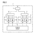
- Fig. 2 shows a block diagram of a possible implementation of pump signal generation apparatus 7 according to the present invention which is adapted to generate a pump signal with a suppressed or reduced optical beat interference noise in the fiber link of the optical network 1.
- the pump signal generation apparatus 7 can form the pump signal generation apparatus 2C used in the co-pumped amplifier 2 or the pump signal generation apparatus 4C used in the counter-pumped amplifier 4 of the network shown in Fig. 1
- the optical pump signal generation apparatus 7 comprises in the shown embodiment two pairs 8, 9 of orthogonal polarization multiplexed pump lasers.
- Each pair 8, 9 of polarization multiplexed pump lasers comprises a first pump laser 8A, 9A and a second pump laser 8B, 9B connected to a corresponding polarization beam combiner 10, 11, as shown in Fig. 2 .
- the polarization beam combiner PBC 9, 10 is adapted to combine the orthogonal polarized laser beams generated by the first and second pump laser of the respective orthogonal pump laser pair.
- Optical signals of the polarization beam combiners 10, 11 can be applied to a WDM multiplexer 12 of the pump signal generation apparatus 7.
- the wavelength of the laser beam generated by the first pump laser 8A and the wavelength of a laser beam generated by the second pump laser 8B of first pair 8 of the polarization multiplexed pump lasers are detuned with respect to each other to suppress an optical beat interference, OBI, noise in a fiber link of the network 1.
- the wavelength of the laser beam generated by the first pump laser 9A and a wavelength of a laser beam generated by the second pump laser 9B of the second pair 9 of polarization multiplexed pump lasers are also detuned with respect to each other to suppress optical beat interference, OBI, noise in the fiber link of the optical network 1.
- each pair 8, 9 of polarization multiplexed pump lasers is connected to a tuning circuit 13 which is adapted to offset a center wavelength of the polarization multiplexed pump lasers.
- both wavelengths ⁇ 1, ⁇ 2 of the laser beams generated by the polarization multiplexed pump lasers are detuned with respect to each other by said tuning circuit 13 which is adapted to detune temperatures T of the respective pump lasers 8A, 8B, 9A, 9B of said pairs 8, 9 of polarization multiplexed pump lasers.
- a pump laser can be formed by a Fabry-Perot laser having a center wavelength stabilized by an external fiber Bragg grating or a multi-longitudinal mode DFB laser.
- a stable center wavelength pump laser source with wide spectral width can be provided using multi-longitudinal modes to suppress SBS and to provide a tailored flat Raman gain in the signal band.
- the interaction of the pump vector and signal vector results in a Raman amplification with a low polarization dependent gain PDG.
- Fig. 3 shows a vector diagram illustrating pump and signal laser polarization directions.
- Fig. 3 shows orthogonal polarization states of a first and second pump laser source obtained after polarization multiplexing using a polarization beam combiner PBC located at the Raman amplifier and the polarization state of the j th data signal laser source after the wavelength division multiplexing WDM component.
- An angle ⁇ j can be defined as the angle between the x-axis and the polarization state of the j th signal laser source.
- the x-component of the optical signal is amplified by the x-component of pump laser P 1,x and pump laser P 2,x .
- the y-component of the signal is amplified by the y-component of the pump laser sources P 1,y and P 2,y .
- the Raman gain is the optical gain or amplification arising from stimulated Raman scattering.
- the Raman gain occurs in transparent solid media of optical fiber.
- L eff is the effective fiber length.
- e x is a pump power in x-direction
- ⁇ f is the frequency offset related to the wavelength offset ⁇ as shown above of the pump laser sources.
- Raman signal gain in the y-direction can be expressed in the same way as defined by equations (1) to (3).
- the optical beat interference OBI is generated by the mixing of the pump signals through the Raman amplification process as expressed by the third term in equation (2).
- Fig. 4B illustrates when the temperature T of one of the two pump laser sources is tuned to a higher temperature of 40°C.
- the tuning of the temperature T of the laser sources can be performed by a tuning circuit 13 as shown in Fig. 2 .
- the wavelength of the laser beams generated by the pump laser sources can be detuned with respect to each other by the tuning circuit 13 which detunes the temperatures T of the respective pump lasers or laser sources of a pair of polarization multiplexed pump lasers.
- the temperature T of one pump laser is varied and results in a change of the relative center wavelengths of the two pump laser sources as shown in Fig. 4B .
- the optical spectrum of the first pump laser PL1 is the same as in Fig.
- Figs. 4A, 4B show an optical spectrum of two polarization division multiplexed pump lasers with center wavelengths nominally at 1457nm and the temperatures T of the two pump lasers being controlled to be at 25°C in the diagram of Fig. 4A . If the temperature of one pump laser is tuned from 25°C to 40°C as shown in the diagram of Fig. 4B an optical beat interference, OBI, does occur with the result of the coupling of the two orthogonal pump modes followed by the Raman signal amplification process.
- OBI optical beat interference
- the occurred optical beat interference, OBI can be enhanced due to an optical Kerr effect, non-linear polarization rotation of the pump fields in the fiber, and polarization coupling of the pump fields caused by non-ideal pump PDM and WDM components in the Raman amplifiers.
- OBI optical beat interference
- the longitudinal mode of the pump laser source can follow a Lorentzian shaped power spectrum.
- the optical power spectrum of the ith pump laser source has several longitudinal modes.
- OSNR OBI ⁇ 4 ⁇ ⁇ j ⁇ k 1 , j ⁇ k 2 , j ⁇ B o ⁇ ⁇ ⁇ f 2 + ⁇ ⁇ f 2 ⁇ f
- k 1,j and k 2,j are the relative intensities of the pump laser longitudinal modes in the x and y polarization directions
- ⁇ f ⁇ f1 + ⁇ f2 is the sum of the spectral width of each pump source longitudinal mode
- ⁇ f is the frequency difference of the two orthogonally polarized pump sources
- B 0 is
- the optical signal-to-noise ratio OSNR improves.
- the optical signal-noise-ratio OSNR improvement provided by the pump signal generation apparatus according to the present invention can be large for a small detuning factor.
- the OSNR penalty expression given below provides the detuning factor.
- the required frequency difference can be expressed as follows: ⁇ f ⁇ 10 ⁇ ⁇ Q 2 ⁇ j k 1 , j ⁇ k 2 , j ⁇ R b ⁇ ⁇ ⁇ f - ⁇ ⁇ f 2
- the maximum wavelength difference ⁇ max is governed by the polarization dependent gain PDG.
- the Raman gain can be usually 16dB. ⁇ f ⁇ 13 ⁇ THz ⁇ G x - G y / G x .
- the counter-/co-pump Raman amplifier gain settings can be set at 20dB/10dB and 15dB/15dB.
- the set-up of the OSNR penalty of the Raman amplified WDM system 1 with and without the wavelength detuning can be compared with each other.
- the OSNR penalty can also be reduced from 1,5dB to 0,5dB for a 20dB/10dB Raman amplified WDM system 1 as shown in Fig. 1 when the co-pump center wavelength is detuned to 0,3nm. In this case the OSNR penalty is 0,9dB for a 15dB/15dB Raman amplified system.
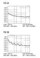
- Figs. 5A, 5B show an average signal RIN spectrum for a 120km TWRS fiber having a counter-/co-pumped Raman amplifier set at 15dB/15dB.
- Fig. 5A shows the average signal RIN spectrum without pump mode interference (no longitudinal mode overlap) and
- Fig. 5B shows the average signal RIN spectrum with pump mode interference (with modes overlapping).
- the spectrally averaged signal RIN of the Raman system with and without optical pump mode mixing is measured according to the diagrams of Figs. 5A, 5B.
- Figs. 5A and 5B compare the spectrally averaged signal RIN of a 80 channel WDM system when the temperature of a pump laser source is tuned from 25°C to 40°C, respectively.
- the detuning of the wavelength of the pump laser is performed by temperature tuning such that the wavelength difference ⁇ is more than 0,3nm ( ⁇ >0,3nm).
- a further possible embodiment can select pump sources with laser center wavelengths having a wavelength difference of more than 0,3nm ( ⁇ >0,3nm).
- RF modulation (dithering) pump source can be performed to broaden the spectral width of longitudinal modes.
- the optical interference is the result of the mixing of two pump optical fields and a signal optical field due to the non-linear Raman scattering processes in the optical fiber of the fiber link.
- the traffic pattern in a WDM optical communication system can change drastically when wavelengths (channels) are added or removed at the network and terminals, wavelengths are switched between deployed network fibers or when a fiber in the network is cut. Accordingly, the optical amplifiers deployed in the optical network may experience large optical power variations due to sudden changes caused by pump optical beat interference, OBI, within the network fiber link. When the WDM information channels are received at the end terminals of the WDM optical communication system these rapid gain variations do generate error bursts which degrade the signal quality.
- OBI pump optical beat interference
- the method and apparatus according to the present invention are provided to suppress optical beat interference, OBI, noise in a fiber link of the optical network 1. This is done in that a wavelength of a laser beam generated by a first pump laser and a wavelength of a laser beam generated by a second pump laser of a pair of polarization multiplexed pump lasers are detuned with respect to each other to suppress the optical beat interference, OBI, noise in the fiber link of the optical network.
- the wavelength difference ⁇ between a first center wavelength of the first pump laser and a second center wavelength of the second pump laser is set such that it exceeds a predetermined minimum wavelength difference ⁇ min .
- This minimum wavelength difference is in a preferred embodiment of the method and apparatus according to the present invention adjusted to be in a range between 0,25nm and 0,3nm. In a specific implementation the minimum wavelength difference ⁇ min is 0,28nm.
- a wavelength difference between the first center wavelength of a first pump laser and a second center wavelength of a second pump laser is in a preferred embodiment set such that it does not exceed a predetermined maximum wavelength difference ⁇ max to minimize a polarization dependent gain PDG.
- the maximum wavelength difference ⁇ max is set to be in a range between 10nm and 15nm.
- the maximum wavelength difference is set to be 11,3nm.
- Other Raman amplifiers used in the optical network in particular in a WDM system 1 according to the present invention, can comprise co-pumped Raman amplifiers. These Raman amplifiers can be formed by distributed Raman amplifiers. In an alternative embodiment the used Raman amplifiers can be formed by lumped Raman amplifiers.
Landscapes
- Physics & Mathematics (AREA)
- Engineering & Computer Science (AREA)
- Computer Networks & Wireless Communication (AREA)
- Signal Processing (AREA)
- Electromagnetism (AREA)
- Condensed Matter Physics & Semiconductors (AREA)
- General Physics & Mathematics (AREA)
- Optics & Photonics (AREA)
- Optical Modulation, Optical Deflection, Nonlinear Optics, Optical Demodulation, Optical Logic Elements (AREA)
Abstract
Description
- The invention relates to a method and an apparatus for suppressing optical beat interference noise, in particular to a method to suppress optical beat interference in Raman amplified WDM systems.
- When light is transmitted through an optical fiber the light signal can be scattered by the vibration of the glass structure of the optical fiber thereby using scattering signal components on the longer wavelength side and shorter wavelength side relative to the wavelength of the incident light. A Raman amplifier is a type of an optical amplifier used in fiber optic transmission systems. The Raman amplification is based on the stimulated Raman scattering phenomenon where a lower frequency signal photon uses a scattering of a higher frequency power pump photon in an optical medium in the non-linear regime. As a result of this, another signal photon is produced, wherein the surplus energy resonantly passes through the vibrational states of the medium. Raman amplifiers can be deployed in long-haul, regional and metro-core fiber optic transmission systems. Distributed Raman amplifiers improve the optical signal to noise ratio and reduce the non-linear penalty of fiber systems, allowing for longer reach, longer amplifiers spans, higher bit rates, higher number of channels, closer channel spacing and operation near the fiber zero dispersion wavelength. Raman scattering of internal light with photons of the gain medium produces photons coherent with the incoming photons. In a Raman amplifier the optical signal can be amplified by Raman amplification.
- Different types of Raman amplifiers are known, e.g. a distributed and a lumped Raman amplifier.
- A distributed Raman amplifier is a Raman amplifier in which the transmission line optical fiber is utilized as the gain medium by multiplexing a pump wavelength with a signal wavelength, whereas a lump Raman amplifier utilizes a dedicated self-contained shorter length of optical fiber to provide amplification. In the case of a lumped Raman amplifier a highly non-linear fiber with a small core such as a dispersion condensating fiber is utilized to increase the interaction between the signal and the pump wavelength. The pump light may be coupled into the transmission fiber in the same direction as a signal (so-called co-directional pumping), in the opposite direction (counter-directional pumping) or in both directions (bidirectional pumping).
- In a co-pumped Raman pump signal relative intensity noise transfer limits the system signal to noise performance of wavelength division multiplexed (WDM) signal channels.
- When using polarization multiplexed pump lasers of similar wavelengths optical beat interference, OBI, can induce sudden and sporadic signal gain and noise variations on the WDM channels. The pump optical beat interference coupled with a non-linear pump signal transfer process within this optical fiber is responsible for this phenomenon. Distributed Raman amplifiers are sensitive to the se sudden and large noise power variations which can cause receivers to loose clock and data recovery for a long period. Large noise power variations may occur randomly over time or at some Raman amplifier gain settings. Accordingly, there is a need to provide a method and apparatus for suppressing optical beat interference noise in an optical network using Raman amplifiers having polarization multiplexed pump lasers.
- The invention provides a method for suppressing optical beat interference noise in a fiber link of an optical network, wherein a wavelength of a laser beam generated by a first pump laser and a wavelength of a laser beam generated by a second pump laser of a pair of polarization multiplexed pump lasers are detuned with respect to each other to suppress the optical beat interference, OBI, noise in the fiber link of said optical network.
- The invention further provides a pump signal generation apparatus adapted to generate a pump signal with suppressed optical beat interference, OBI, noise in a fiber link of an optical network, said apparatus comprising at least one pair of polarization multiplexed pump lasers having wavelengths which are detuned with respect to each other to suppress the optical beat interference, OBI, noise in the fiber link of said optical network.
- In a possible embodiment of the apparatus according to the present invention each pair of polarization multiplexed pump lasers comprises a first pump laser and a second pump laser connected to a corresponding polarization beam combiner adapted to combine the orthogonal polarized laser beams generated by the first and second pump laser.
- In a still further embodiment of the apparatus according to the present invention a wavelength of a laser beam generated by the first pump laser and a wavelength of a laser beam generated by the second pump laser of each pair of polarization multiplexed pump lasers are detuned with respect to each other to suppress the optical beat interference noise.
- In a further possible embodiment of the apparatus according to the present invention each pair of polarization multiplexed pump lasers is connected to a tuning circuit adapted to offset the center wavelengths of the polarization multiplexed pump lasers.
- In a further possible embodiment of the apparatus according to the present invention both wavelengths of the laser beams are detuned with respect to each other by said tuning circuit which is adapted to detune temperatures of the respective pump lasers of said pair of polarization multiplexed pump lasers.
- In a further possible embodiment of the apparatus according to the present invention a wavelength difference between a first center wavelength of the first pump laser and a second center wavelength of the second pump laser is set such that it exceeds a predetermined minimum wavelength difference.
- In a possible embodiment of the apparatus according to the present invention the minimum wavelength difference is in a range between 0,25nm and 0,3nm.
- In a specific implementation of the apparatus according to the present invention the minimum wavelength difference is set to be 0,28nm.
- In a still further possible embodiment of the apparatus according to the present invention a wavelength difference between a first center wavelength of a first pump laser and a second center wavelength of a second pump laser is set such that it does not exceed a predetermined maximum wavelength difference to minimize a polarization dependent gain.
- In a further possible embodiment of the apparatus according to the present invention said maximum wavelength difference is in a range between 10nm and 15nm.
- In a specific advantageous implementation the maximum wavelength difference is set to be 11,3nm.
- In a possible embodiment of the apparatus according to the present invention the polarization multiplexed pump lasers are formed by Fabry-Perot lasers each having a center wavelength stabilized by an external fiber Bragg grating or formed by multi-longitudinal mode DFB lasers.
- In a possible embodiment of the apparatus according to the present invention said polarization beam combiners of different pairs of polarization multiplexed pump lasers are connected to a WDM multiplexer.
- The invention further provides a Raman amplifier comprising at least one pump signal generation apparatus adapted to generate a pump signal with suppressed optical beat interference noise comprising at least one pair of polarization multiplexed pump lasers having wavelengths which are detuned with respect to each other to suppress the optical beat interference, OBI, noise in the fiber link of an optical network,
wherein said Raman amplifier further comprises a WDM multiplexer adapted to multiplex an optical pump signal generated by said pump signal generation apparatus with optical data signals to generate an optical transmission signal supplied to a transmission line fiber of said fiber link. - In a possible embodiment of the Raman amplifier according to the present invention said Raman amplifier is a co-pumped Raman amplifier.
- In a further possible embodiment of the Raman amplifier according to the present invention said Raman amplifier is a distributed Raman amplifier or a lumped Raman amplifier.
- The invention further provides a wavelength division multiplexing system comprising at least one Raman amplifier having at least one pump signal generation apparatus adapted to generate a pump signal with suppressed optical beat interference, OBI, noise in a fiber link of an optical network, said signal generation apparatus comprising at least one pair of polarization multiplexed pump lasers having wavelengths which are detuned with respect to each other to suppress the optical beat interference, OBI, noise in the fiber link of said optical network,
said Raman amplifier further comprising a WDM multiplexer adapted to multiplex an optical pump signal generated by said pump signal generation apparatus with optical data signals to generate an optical transmission signal supplied to a transmission line fiber of said fiber link. - Fig. 1
- shows a block diagram of a possible implementation of a Raman amplified WDM system according to the present invention;
- Fig. 2
- shows a block diagram of a possible implementation of a pump signal generation apparatus with suppressed optical beat interference according to the present invention;
- Fig. 3
- shows a vector diagram showing pump and signal laser polarization directions for illustrating operation of an apparatus according to the present invention;
- Fig. 4A, 4B
- shows diagrams for illustrating an optical spectrum of two polarization division multiplexed pump lasers for illustrating the operation of the apparatus according to the present invention;
- Fig. 5A, 5B
- shows diagrams showing averaged signal RIN spectrum for illustrating an operation of an apparatus according to the present invention.
- In the following possible embodiments and implementations of an apparatus and a method for suppressing optical beat interference noise in an optical network are explained in more detail with reference to the enclosed figures.
- As can be seen from
Fig. 1 the optical network 1 according to the present invention can comprise at least one co-pumpedoptical amplifier 2 connected via atransmission line fiber 3 of a fiber link to a counter-pumpedoptical amplifier 4 as shown inFig. 1 . Theco-pumped amplifier 2 is an optical amplifier, in particular a co-pumped optical Raman amplifier. Thecounter-pumped amplifier 4 is an optical amplifier, in particular a counter-pumped Raman amplifier. The co-pumpedoptical amplifier 2 is connected at its input 3A to an optical signal source 5 supplying optical data signals S1, S2,... SN which are wavelength division multiplexed. Theco-pumped Raman amplifier 2 comprises aWDM multiplexer 2B to which the pumpsignal generation apparatus 2C is connected as shown inFig. 1 . TheWDM multiplexer 2B is adapted to multiplex the optical pump signals P1, P2...PM generated by the pumpsignal generation apparatus 2C with the optical data signals S1, S2,... SN to generate an optical transmission signal supplied to thetransmission line fiber 3 of said fiber link at theoutput 2D of theco-pumped amplifier 2. The optical transmission signal travels through thetransmission line fiber 3 to aninput 4A of thecounter-pumped Raman amplifier 4 as shown inFig. 1 . Thecounter-pumped amplifier 4 comprises in the shown embodiment aWDM multiplexer 4B connected to the pumpsignal generation apparatus 4C. Theoutput 4D of the counter-pumpedoptical amplifier 4 out-puts the optical data signal to a data signal evaluation unit 6 as shown inFig. 1 . The performance of the co- andcounter-pumped Raman amplifiers Fig. 1 , can be constrained by signal polarization dependent gain PDG, signal-pump-signal depletion modulation crosstalk and pump-signal intensity noise transfer. Optical data signals are wavelength division multiplexed at the remote node. The pump signals P1, P2, ..., PM generated by the pumpsignal generation apparatus 2C or by the pumpsignal generation apparatus 4C are polarization multiplexed and wavelength division multiplexed at the local Raman amplifiers. - The signal-pump-signal depletion modulation crosstalk and pump-signal intensity noise transfer can be minimized in a counter-pumped Raman amplifier configuration. The signal polarization dependent gain PDG in both co- or counter-pumped Raman amplifier of the optical network 1 as shown in
Fig. 1 are reduced by using pump lasers having an identical center wavelength, identical optical power and orthogonal polarization states. The state of polarization of the pump field is ideally linear whereas the state of polarization of the signal field travelling along thetransmission line fiber 3 is arbitrary. - In the implementation as shown in
Fig. 1 the optical network 1 is a Raman amplified WDM optical system comprising a pumpsignal generation apparatus co-pumped amplifier 2 and acounter-pumped amplifier 4. The pump signal generation apparatus used in theoptical amplifiers - The used optical pump
signal generation apparatus -
Fig. 2 shows a block diagram of a possible implementation of pumpsignal generation apparatus 7 according to the present invention which is adapted to generate a pump signal with a suppressed or reduced optical beat interference noise in the fiber link of the optical network 1. The pumpsignal generation apparatus 7 can form the pumpsignal generation apparatus 2C used in theco-pumped amplifier 2 or the pumpsignal generation apparatus 4C used in thecounter-pumped amplifier 4 of the network shown inFig. 1 - As can be shown in the embodiment of
Fig. 2 the optical pumpsignal generation apparatus 7 comprises in the shown embodiment two pairs 8, 9 of orthogonal polarization multiplexed pump lasers. Each pair 8, 9 of polarization multiplexed pump lasers comprises a first pump laser 8A, 9A and a second pump laser 8B, 9B connected to a correspondingpolarization beam combiner Fig. 2 . The polarizationbeam combiner PBC 9, 10 is adapted to combine the orthogonal polarized laser beams generated by the first and second pump laser of the respective orthogonal pump laser pair. Optical signals of thepolarization beam combiners WDM multiplexer 12 of the pumpsignal generation apparatus 7. The wavelength of the laser beam generated by the first pump laser 8A and the wavelength of a laser beam generated by the second pump laser 8B of first pair 8 of the polarization multiplexed pump lasers are detuned with respect to each other to suppress an optical beat interference, OBI, noise in a fiber link of the network 1. The wavelength of the laser beam generated by the first pump laser 9A and a wavelength of a laser beam generated by the second pump laser 9B of the second pair 9 of polarization multiplexed pump lasers are also detuned with respect to each other to suppress optical beat interference, OBI, noise in the fiber link of the optical network 1. - As can be seen in
Fig. 2 in the shown implementation each pair 8, 9 of polarization multiplexed pump lasers is connected to atuning circuit 13 which is adapted to offset a center wavelength of the polarization multiplexed pump lasers. In a possible embodiment both wavelengths λ1, λ2 of the laser beams generated by the polarization multiplexed pump lasers are detuned with respect to each other by said tuningcircuit 13 which is adapted to detune temperatures T of the respective pump lasers 8A, 8B, 9A, 9B of said pairs 8, 9 of polarization multiplexed pump lasers. In a possible implementation a pump laser can be formed by a Fabry-Perot laser having a center wavelength stabilized by an external fiber Bragg grating or a multi-longitudinal mode DFB laser. A stable center wavelength pump laser source with wide spectral width can be provided using multi-longitudinal modes to suppress SBS and to provide a tailored flat Raman gain in the signal band. The interaction of the pump vector and signal vector results in a Raman amplification with a low polarization dependent gain PDG. -
Fig. 3 shows a vector diagram illustrating pump and signal laser polarization directions.Fig. 3 shows orthogonal polarization states of a first and second pump laser source obtained after polarization multiplexing using a polarization beam combiner PBC located at the Raman amplifier and the polarization state of the jth data signal laser source after the wavelength division multiplexing WDM component. An angle φj can be defined as the angle between the x-axis and the polarization state of the jth signal laser source. The x-component of the optical signal is amplified by the x-component of pump laser P1,x and pump laser P2,x. Similarly, the y-component of the signal is amplified by the y-component of the pump laser sources P1,y and P2,y. - The Raman gain is the optical gain or amplification arising from stimulated Raman scattering. The Raman gain occurs in transparent solid media of optical fiber.
- In the pump
signal generation apparatus 7 according to the present invention the Raman signal gain in the x-axis is defined by:
- Leff is the effective fiber length.


wherein ex is a pump power in x-direction and δf is the frequency offset related to the wavelength offset δλ as shown above of the pump laser sources. Raman signal gain in the y-direction can be expressed in the same way as defined by equations (1) to (3). - The optical beat interference OBI is generated by the mixing of the pump signals through the Raman amplification process as expressed by the third term in equation (2).
Fig. 4A shows an optical spectrum of a polarization multiplexed pump laser where a temperature T of both pump lasers are controlled to be 25°C (T=25°C).Fig. 4B illustrates when the temperature T of one of the two pump laser sources is tuned to a higher temperature of 40°C. In a possible implementation the tuning of the temperature T of the laser sources can be performed by atuning circuit 13 as shown inFig. 2 . The wavelength of the laser beams generated by the pump laser sources can be detuned with respect to each other by thetuning circuit 13 which detunes the temperatures T of the respective pump lasers or laser sources of a pair of polarization multiplexed pump lasers. The temperature T of one pump laser is varied and results in a change of the relative center wavelengths of the two pump laser sources as shown inFig. 4B . The optical spectrum shown inFig. 4A shows the spectrum of a first pump laser PL1 and of a second pump laser PL2 tuned to a temperature of T=25°C. In contrast, in the diagram ofFig. 4B the optical spectrum of the first pump laser PL1 is the same as inFig. 4A and corresponding to a tuning temperature T of 25°C, whereas the optical spectrum of the second pump laser PL2 is shifted slightly by tuning its temperature T to a higher temperature of 40°C.Figs. 4A, 4B show an optical spectrum of two polarization division multiplexed pump lasers with center wavelengths nominally at 1457nm and the temperatures T of the two pump lasers being controlled to be at 25°C in the diagram ofFig. 4A . If the temperature of one pump laser is tuned from 25°C to 40°C as shown in the diagram ofFig. 4B an optical beat interference, OBI, does occur with the result of the coupling of the two orthogonal pump modes followed by the Raman signal amplification process. - The occurred optical beat interference, OBI, can be enhanced due to an optical Kerr effect, non-linear polarization rotation of the pump fields in the fiber, and polarization coupling of the pump fields caused by non-ideal pump PDM and WDM components in the Raman amplifiers. As can be seen from
Figs. 4A, 4B , the main longitudinal mode overlaps as shown inFig. 4B . The longitudinal mode of the pump laser source can follow a Lorentzian shaped power spectrum. The optical power spectrum of the ith pump laser source has several longitudinal modes. The mixing of the Raman amplified signal wavelength through photodetection process can produce an optical signal-to-noise ratio OSNR due to pump mode optical interference noise transferred to the signal by:
wherein k1,j and k2,j are the relative intensities of the pump laser longitudinal modes in the x and y polarization directions,
Δ f = Δf1 + Δf2 is the sum of the spectral width of each pump source longitudinal mode, and
δ f is the frequency difference of the two orthogonally polarized pump sources, and
B0 is the optical bandwidth. - As the source linewidth increases, for example, due to dithering, the optical signal-to-noise ratio OSNR improves.
- For typical pump laser values Σk1,jk2,j=0,125 and Δf1=Δf2=1,25GHz (Δλ=0,01nm) the optical signal-to-noise ratio of the optical beat interference OSNROBI=36,5dB when δλ=0,3nm, i.e. when the pump mode overlap does not occur, and OSNROBI=27dB when δλ=0,1nm, i.e. when the pump mode overlap occurs.
- The optical signal-noise-ratio OSNR improvement provided by the pump signal generation apparatus according to the present invention can be large for a small detuning factor. The OSNR penalty expression given below provides the detuning factor. As a rule of thumb for WDM systems a 0,5dB OSNR penalty can be allocated for such penalties

wherein Rb is the baud-rate and
Q is a factor related to the required bit error rate, BER, during signal transmission. - Accordingly, the required frequency difference can be expressed as follows:

The pump laser wavelength difference can be calculated using equation (6) indicated above. For example, when BER=10-12 (responding to Q=7,036) is required for no FEC cases, it can be calculated through the required pump wavelength difference for different baud-rates Rb. Using digital modulation schemes such as NRZ, QPSK, and QAM does not require a baud-rate Rb to be greater than 25Gbaud/sec. Also, if FEC is used in higher data rate WDM systems the Q factor may be lower. The universal expression given in equation (6) gives a minimum wavelength difference δλmin=0,28nm (corresponding to δfmin=35GHz). - The maximum wavelength difference δλmax is governed by the polarization dependent gain PDG. The PDG penalty in a wavelength division multiplexing system is to be δG=0,5dB. In an ideal case Gx=Gy, however in a real scenario the polarization dependent gain PDG causes that Gy=Gx-δG. The Raman gain can be usually 16dB.

- Accordingly, a maximum wavelength difference δλmax can be calculated to be δλmax=11,3nm (corresponding to δλmax=1,4THz).
- One can measure the OSNR penalty of a WDM optical network system as shown in
Fig. 1 at a bit error rate (BER=10-12 corresponding to Q=7,036) for a baut-rate Rb=10,709Gb/sec data rate link including a fixed decision threshold receiver. The counter-/co-pump Raman amplifier gain settings can be set at 20dB/10dB and 15dB/15dB. The set-up of the OSNR penalty of the Raman amplified WDM system 1 with and without the wavelength detuning can be compared with each other. The OSNR penalty can also be reduced from 1,5dB to 0,5dB for a 20dB/10dB Raman amplified WDM system 1 as shown inFig. 1 when the co-pump center wavelength is detuned to 0,3nm. In this case the OSNR penalty is 0,9dB for a 15dB/15dB Raman amplified system. -
Figs. 5A, 5B show an average signal RIN spectrum for a 120km TWRS fiber having a counter-/co-pumped Raman amplifier set at 15dB/15dB.Fig. 5A shows the average signal RIN spectrum without pump mode interference (no longitudinal mode overlap) andFig. 5B shows the average signal RIN spectrum with pump mode interference (with modes overlapping). - Accordingly, the spectrally averaged signal RIN of the Raman system with and without optical pump mode mixing is measured according to the diagrams of
Figs. 5A, 5B. Figs. 5A and 5B compare the spectrally averaged signal RIN of a 80 channel WDM system when the temperature of a pump laser source is tuned from 25°C to 40°C, respectively. An OSNR and RIN are related as:
- When the center wavelength difference of the pump laser sources is increased by detuning through tuning the laser temperature T or selecting center wavelengths greater than 0.3nm the pump mode interference noise and gain fluctuation is reduced drastically. A similar improvement can be reached when pump lasers are modulated by subcarrier modulation.
- Accordingly, there are three different ways to reduce pump mode induced optical beat interference, OBI, noise in a Raman amplified WDM system.
- In a first possible embodiment the detuning of the wavelength of the pump laser is performed by temperature tuning such that the wavelength difference δλ is more than 0,3nm (δλ>0,3nm).
- A further possible embodiment can select pump sources with laser center wavelengths having a wavelength difference of more than 0,3nm (δλ>0,3nm).
- In a further possible embodiment RF modulation (dithering) pump source can be performed to broaden the spectral width of longitudinal modes.
- The optical interference is the result of the mixing of two pump optical fields and a signal optical field due to the non-linear Raman scattering processes in the optical fiber of the fiber link. With the method according to the present invention by employing a detuned pump wavelength the optical beat interference, OBI, noise and signal gain fluctuations are eliminated to improve a signal-to-noise ratio SNR and a BER (bit error rate) performance of the optical WDM system according to the present invention.
- The traffic pattern in a WDM optical communication system can change drastically when wavelengths (channels) are added or removed at the network and terminals, wavelengths are switched between deployed network fibers or when a fiber in the network is cut. Accordingly, the optical amplifiers deployed in the optical network may experience large optical power variations due to sudden changes caused by pump optical beat interference, OBI, within the network fiber link. When the WDM information channels are received at the end terminals of the WDM optical communication system these rapid gain variations do generate error bursts which degrade the signal quality.
- With the apparatus and method according to the present invention it is possible to reduce these sudden and sporadic bit errors, in particular in forward error corrected FEC 10G , 100G and 1T, Raman amplifiers used in high capacity WDM systems. Accordingly, with the method and apparatus according to the present invention a transmission distance and regenerator spacing of high capacity WDM channels using Raman amplification can be extended.
- The method and apparatus according to the present invention are provided to suppress optical beat interference, OBI, noise in a fiber link of the optical network 1. This is done in that a wavelength of a laser beam generated by a first pump laser and a wavelength of a laser beam generated by a second pump laser of a pair of polarization multiplexed pump lasers are detuned with respect to each other to suppress the optical beat interference, OBI, noise in the fiber link of the optical network. The wavelength difference δλ between a first center wavelength of the first pump laser and a second center wavelength of the second pump laser is set such that it exceeds a predetermined minimum wavelength difference δλmin. This minimum wavelength difference is in a preferred embodiment of the method and apparatus according to the present invention adjusted to be in a range between 0,25nm and 0,3nm. In a specific implementation the minimum wavelength difference δλmin is 0,28nm.
- Further, a wavelength difference between the first center wavelength of a first pump laser and a second center wavelength of a second pump laser is in a preferred embodiment set such that it does not exceed a predetermined maximum wavelength difference δλmax to minimize a polarization dependent gain PDG. In a possible implementation the maximum wavelength difference δλmax is set to be in a range between 10nm and 15nm. In a specific implementation the maximum wavelength difference is set to be 11,3nm. Other Raman amplifiers used in the optical network, in particular in a WDM system 1 according to the present invention, can comprise co-pumped Raman amplifiers. These Raman amplifiers can be formed by distributed Raman amplifiers. In an alternative embodiment the used Raman amplifiers can be formed by lumped Raman amplifiers.
Claims (16)
- A method for suppressing optical beat interference noise in a fiber link of an optical network,
wherein a wavelength of a laser beam generated by a first pump laser and a wavelength of a laser beam generated by a second pump laser of a pair of polarization multiplexed pump lasers are detuned with respect to each other to suppress the optical beat interference, OBI, noise in the fiber link of said optical network. - A pump signal generation apparatus (7) adapted to generate a pump signal with suppressed optical beat interference, OBI, noise in a fiber link of an optical network, comprising
at least one pair (8, 9) of polarization multiplexed pump lasers having wavelengths which are detuned with respect to each other to suppress the optical beat interference, OBI, noise in the fiber link of said optical network. - The apparatus according to claim 2,
wherein each pair (8, 9) of polarization multiplexed pump lasers comprises a first pump laser (8A; 9A) and a second pump laser (8B; 9B) connected to a corresponding polarization beam combiner (10, 11) adapted to combine the orthogonal polarized laser beams generated by the first and second pump laser. - The apparatus according to claim 3,
wherein a wavelength of a laser beam generated by the first pump laser (8A; 9A) and a wavelength of a laser beam generated by the second pump laser (8B; 9B) of each pair of polarization multiplexed pump lasers are detuned with respect to each other to suppress the optical beat interference noise. - The apparatus according to claim 4,
wherein each pair of polarization multiplexed pump lasers is connected to a tuning circuit (13) adapted to offset the center wavelengths of the polarization multiplexed pump lasers. - The apparatus according to claim 5,
wherein both wavelengths of the laser beams are detuned with respect to each other by said tuning circuit (13) which is adapted to detune temperatures of the respective pump lasers of said pair (8, 9) of polarization multiplexed pump lasers. - The apparatus according to claim 4,
wherein a wavelength difference between a first center wavelength of the first pump laser (8A; 9A) and a second center wavelength of the second pump laser (8B; 9B) is set such that it exceeds a predetermined minimum wavelength difference. - The apparatus according to claim 7,
wherein said minimum wavelength difference is set to be in a range between 0,25 nm and 0,3 nm, in particular 0,28 nm. - The apparatus according to claim 3,
wherein a wavelength difference between a first center wavelength of a first pump laser (8A; 9A) and a second center wavelength of a second pump laser (8B; 9B) is set such that it does not exceed a predetermined maximum wavelength difference to minimize a polarization dependent gain. - The apparatus according to claim 9,
wherein said maximum wavelength difference is set to be in a range between 10 nm and 15 nm, in particular 11,3 nm. - The apparatus according to claim 2,
wherein said polarization multiplexed pump lasers are Fabry-Perot lasers each having a center wavelength stabilized by an external fiber Bragg grating or multi-longitudinal mode DFB lasers. - The apparatus according to claim 3,
wherein said polarization beam combiners (10, 11) of different pairs of polarization multiplexed pump lasers are connected to a WDM multiplexer. - A Raman amplifier (2) comprising at least one pump signal generation apparatus (7) according to claim 2 and a WDM multiplexer (2B) adapted to multiplex an optical pump signal generated by said pump signal generation apparatus (7) with optical data signals to generate an optical transmission signal supplied to a transmission line fiber (3) of said fiber link.
- The Raman amplifier according to claim 13,
wherein said Raman amplifier (2) is a co-pumped Raman amplifier. - The Raman amplifier according to claim 13,
wherein said Raman amplifier (2) is a distributed Raman amplifier or a lumped Raman amplifier. - A wavelength division multiplexing (WDM) system comprising at least one Raman amplifier (2) according to claim 13.
Applications Claiming Priority (1)
| Application Number | Priority Date | Filing Date | Title |
|---|---|---|---|
| US13/600,458 US8903249B2 (en) | 2012-08-31 | 2012-08-31 | Method and apparatus for suppressing optical beat interference noise in raman amplifiers |
Publications (2)
| Publication Number | Publication Date |
|---|---|
| EP2704338A1 true EP2704338A1 (en) | 2014-03-05 |
| EP2704338B1 EP2704338B1 (en) | 2017-10-25 |
Family
ID=48874121
Family Applications (1)
| Application Number | Title | Priority Date | Filing Date |
|---|---|---|---|
| EP13176936.6A Active EP2704338B1 (en) | 2012-08-31 | 2013-07-17 | Method and apparatus for suppressing optical beat interference noise |
Country Status (2)
| Country | Link |
|---|---|
| US (1) | US8903249B2 (en) |
| EP (1) | EP2704338B1 (en) |
Families Citing this family (5)
| Publication number | Priority date | Publication date | Assignee | Title |
|---|---|---|---|---|
| US20130208762A1 (en) * | 2012-02-14 | 2013-08-15 | Halliburton Energy Services Inc. | Suppression of Stimulated Raman Scattering |
| JP2015007612A (en) * | 2013-05-31 | 2015-01-15 | キヤノン株式会社 | Light source adjustment means, optical measuring device, subject information acquisition system, and wavelength adjustment program |
| US9705598B2 (en) * | 2014-04-03 | 2017-07-11 | Commscope, Inc. Of North Carolina | Methods and systems for reducing optical beat interference via polarization diversity in FTTx networks |
| WO2022133685A1 (en) * | 2020-12-21 | 2022-06-30 | 西安科锐盛创新科技有限公司 | Optical fiber microwave frequency transfer method based on laser frequency offset locking |
| WO2023162141A1 (en) * | 2022-02-25 | 2023-08-31 | 日本電信電話株式会社 | Excitation light generation device and excitation light generation method |
Citations (3)
| Publication number | Priority date | Publication date | Assignee | Title |
|---|---|---|---|---|
| US6359725B1 (en) * | 1998-06-16 | 2002-03-19 | Xtera Communications, Inc. | Multi-stage optical amplifier and broadband communication system |
| US6646786B1 (en) * | 2002-05-06 | 2003-11-11 | Cisco Technology, Inc. | Copropagating Raman pump unit to suppress four-wave mixing crosstalk between pump modes and WDM signals |
| US7054059B1 (en) * | 2003-05-14 | 2006-05-30 | Cisco Technoloy, Inc. | Lumped Raman amplification structure for very wideband applications |
Family Cites Families (5)
| Publication number | Priority date | Publication date | Assignee | Title |
|---|---|---|---|---|
| EP2306604B1 (en) * | 1998-07-23 | 2012-09-05 | The Furukawa Electric Co., Ltd. | Optical repeater comprising a Raman amplifier |
| JP3527671B2 (en) * | 1999-04-23 | 2004-05-17 | 富士通株式会社 | Method of controlling wavelength characteristics of optical transmission power by Raman amplification, wavelength division multiplexing optical communication system and optical amplifier using the same |
| US6611370B2 (en) * | 1999-07-23 | 2003-08-26 | The Furukawa Electric Co., Ltd. | Raman amplifier system, apparatus and method for identifying, obtaining and maintaining an arbitrary Raman amplification performance |
| US7199919B2 (en) * | 2002-03-15 | 2007-04-03 | The Furukawa Electric Co., Ltd. | Tunable multimode wavelength division multiplex Raman pump and amplifier, and a system, method, and computer program product for controlling tunable Raman pumps, and Raman amplifiers |
| JP4679651B2 (en) * | 2008-09-19 | 2011-04-27 | 富士通株式会社 | Raman amplifier and control method thereof |
-
2012
- 2012-08-31 US US13/600,458 patent/US8903249B2/en active Active
-
2013
- 2013-07-17 EP EP13176936.6A patent/EP2704338B1/en active Active
Patent Citations (3)
| Publication number | Priority date | Publication date | Assignee | Title |
|---|---|---|---|---|
| US6359725B1 (en) * | 1998-06-16 | 2002-03-19 | Xtera Communications, Inc. | Multi-stage optical amplifier and broadband communication system |
| US6646786B1 (en) * | 2002-05-06 | 2003-11-11 | Cisco Technology, Inc. | Copropagating Raman pump unit to suppress four-wave mixing crosstalk between pump modes and WDM signals |
| US7054059B1 (en) * | 2003-05-14 | 2006-05-30 | Cisco Technoloy, Inc. | Lumped Raman amplification structure for very wideband applications |
Non-Patent Citations (1)
| Title |
|---|
| EUI S. SON ET AL: "<title>Pump-to-signal crosstalk in Raman amplifier systems using polarization-multiplexed pump lasers</title>", PROCEEDINGS OF SPIE, vol. 4906, 23 August 2002 (2002-08-23), pages 35 - 42, XP055088692, ISSN: 0277-786X, DOI: 10.1117/12.480590 * |
Also Published As
| Publication number | Publication date |
|---|---|
| EP2704338B1 (en) | 2017-10-25 |
| US8903249B2 (en) | 2014-12-02 |
| US20140064728A1 (en) | 2014-03-06 |
Similar Documents
| Publication | Publication Date | Title |
|---|---|---|
| US10651820B2 (en) | Signal processing apparatus and method for transmitting and receiving coherent parallel optical signals | |
| US7414728B2 (en) | Reconfigurable polarization independent interferometers and methods of stabilization | |
| CA2335166C (en) | Optical communication system with co-propagating pump radiation for raman amplification | |
| JP4626918B2 (en) | Raman optical repeater | |
| Zhu et al. | High spectral density long-haul 40-Gb/s transmission using CSRZ-DPSK format | |
| US8977137B2 (en) | Polarization dependent loss compensation | |
| US20080285977A1 (en) | Method and apparatus for transmitting optical signals | |
| US8452193B2 (en) | Optical receiver | |
| EP2704338B1 (en) | Method and apparatus for suppressing optical beat interference noise | |
| JP4746126B2 (en) | Depolarized WDM source | |
| EP4040612B1 (en) | Servo-stabilized phase demodulated fiber amplifier system | |
| Lange et al. | Sub-nanosecond optical switching using chip-based soliton microcombs | |
| EP2458751B1 (en) | Optical communication system and method | |
| JP5304650B2 (en) | Optical signal processing device | |
| US12348267B1 (en) | Broadband optical system with semiconductor optical amplifier | |
| US20060188267A1 (en) | System and method for suppression of stimulated Brillouin scattering in optical transmission communications | |
| Vujicic et al. | Quantum dash passively mode-locked lasers for Tbit/s data interconnects | |
| Khan | Quantum-dash laser-based tunable 50/75 GHz mmW transport system for future L-band networks | |
| Al-Taiy et al. | Ultra-narrow line-width, stable and widely tuneable laser source for coherent optical communication systems | |
| Chuang et al. | Demonstration of Fully Integrated $6\lambda\times 200$ Gbps (1.2 Tbps) PICs and Transceivers in L-Band | |
| Dasan et al. | Optically multiplexed systems: wavelength division multiplexing | |
| Yoshida et al. | Single-channel 3.84 Tbit/s, 64 QAM coherent Nyquist pulse transmission over 150 km with frequency-stabilized and mode-locked laser | |
| Neuhauser et al. | New remote pump scheme enabling high-capacity (3.2 Tb/s) unrepeatered C+ L band transmission over 220 km | |
| Bakare et al. | Optimization of Hybrid Optical Amplifiers for Enhanced WDM Efficiency | |
| Foursa et al. | Nonlinear interaction between signal and amplified spontaneous emission in coherent systems |
Legal Events
| Date | Code | Title | Description |
|---|---|---|---|
| AK | Designated contracting states |
Kind code of ref document: A1 Designated state(s): AL AT BE BG CH CY CZ DE DK EE ES FI FR GB GR HR HU IE IS IT LI LT LU LV MC MK MT NL NO PL PT RO RS SE SI SK SM TR |
|
| AX | Request for extension of the european patent |
Extension state: BA ME |
|
| PUAI | Public reference made under article 153(3) epc to a published international application that has entered the european phase |
Free format text: ORIGINAL CODE: 0009012 |
|
| 17P | Request for examination filed |
Effective date: 20140407 |
|
| RBV | Designated contracting states (corrected) |
Designated state(s): AL AT BE BG CH CY CZ DE DK EE ES FI FR GB GR HR HU IE IS IT LI LT LU LV MC MK MT NL NO PL PT RO RS SE SI SK SM TR |
|
| 17Q | First examination report despatched |
Effective date: 20160920 |
|
| STAA | Information on the status of an ep patent application or granted ep patent |
Free format text: STATUS: EXAMINATION IS IN PROGRESS |
|
| GRAP | Despatch of communication of intention to grant a patent |
Free format text: ORIGINAL CODE: EPIDOSNIGR1 |
|
| STAA | Information on the status of an ep patent application or granted ep patent |
Free format text: STATUS: GRANT OF PATENT IS INTENDED |
|
| RIC1 | Information provided on ipc code assigned before grant |
Ipc: H04J 14/02 20060101ALI20170619BHEP Ipc: H04B 10/291 20130101ALI20170619BHEP Ipc: H04B 10/2507 20130101AFI20170619BHEP Ipc: H04J 14/06 20060101ALI20170619BHEP |
|
| INTG | Intention to grant announced |
Effective date: 20170707 |
|
| GRAS | Grant fee paid |
Free format text: ORIGINAL CODE: EPIDOSNIGR3 |
|
| GRAA | (expected) grant |
Free format text: ORIGINAL CODE: 0009210 |
|
| STAA | Information on the status of an ep patent application or granted ep patent |
Free format text: STATUS: THE PATENT HAS BEEN GRANTED |
|
| AK | Designated contracting states |
Kind code of ref document: B1 Designated state(s): AL AT BE BG CH CY CZ DE DK EE ES FI FR GB GR HR HU IE IS IT LI LT LU LV MC MK MT NL NO PL PT RO RS SE SI SK SM TR |
|
| RAP1 | Party data changed (applicant data changed or rights of an application transferred) |
Owner name: ADVA OPTICAL NETWORKING SE |
|
| REG | Reference to a national code |
Ref country code: GB Ref legal event code: FG4D |
|
| REG | Reference to a national code |
Ref country code: CH Ref legal event code: EP |
|
| REG | Reference to a national code |
Ref country code: AT Ref legal event code: REF Ref document number: 940815 Country of ref document: AT Kind code of ref document: T Effective date: 20171115 |
|
| REG | Reference to a national code |
Ref country code: IE Ref legal event code: FG4D |
|
| REG | Reference to a national code |
Ref country code: DE Ref legal event code: R096 Ref document number: 602013028312 Country of ref document: DE |
|
| REG | Reference to a national code |
Ref country code: NL Ref legal event code: MP Effective date: 20171025 |
|
| REG | Reference to a national code |
Ref country code: LT Ref legal event code: MG4D |
|
| REG | Reference to a national code |
Ref country code: AT Ref legal event code: MK05 Ref document number: 940815 Country of ref document: AT Kind code of ref document: T Effective date: 20171025 |
|
| PG25 | Lapsed in a contracting state [announced via postgrant information from national office to epo] |
Ref country code: NL Free format text: LAPSE BECAUSE OF FAILURE TO SUBMIT A TRANSLATION OF THE DESCRIPTION OR TO PAY THE FEE WITHIN THE PRESCRIBED TIME-LIMIT Effective date: 20171025 |
|
| PG25 | Lapsed in a contracting state [announced via postgrant information from national office to epo] |
Ref country code: ES Free format text: LAPSE BECAUSE OF FAILURE TO SUBMIT A TRANSLATION OF THE DESCRIPTION OR TO PAY THE FEE WITHIN THE PRESCRIBED TIME-LIMIT Effective date: 20171025 Ref country code: LT Free format text: LAPSE BECAUSE OF FAILURE TO SUBMIT A TRANSLATION OF THE DESCRIPTION OR TO PAY THE FEE WITHIN THE PRESCRIBED TIME-LIMIT Effective date: 20171025 Ref country code: FI Free format text: LAPSE BECAUSE OF FAILURE TO SUBMIT A TRANSLATION OF THE DESCRIPTION OR TO PAY THE FEE WITHIN THE PRESCRIBED TIME-LIMIT Effective date: 20171025 Ref country code: SE Free format text: LAPSE BECAUSE OF FAILURE TO SUBMIT A TRANSLATION OF THE DESCRIPTION OR TO PAY THE FEE WITHIN THE PRESCRIBED TIME-LIMIT Effective date: 20171025 Ref country code: NO Free format text: LAPSE BECAUSE OF FAILURE TO SUBMIT A TRANSLATION OF THE DESCRIPTION OR TO PAY THE FEE WITHIN THE PRESCRIBED TIME-LIMIT Effective date: 20180125 |
|
| PG25 | Lapsed in a contracting state [announced via postgrant information from national office to epo] |
Ref country code: AT Free format text: LAPSE BECAUSE OF FAILURE TO SUBMIT A TRANSLATION OF THE DESCRIPTION OR TO PAY THE FEE WITHIN THE PRESCRIBED TIME-LIMIT Effective date: 20171025 Ref country code: BG Free format text: LAPSE BECAUSE OF FAILURE TO SUBMIT A TRANSLATION OF THE DESCRIPTION OR TO PAY THE FEE WITHIN THE PRESCRIBED TIME-LIMIT Effective date: 20180125 Ref country code: LV Free format text: LAPSE BECAUSE OF FAILURE TO SUBMIT A TRANSLATION OF THE DESCRIPTION OR TO PAY THE FEE WITHIN THE PRESCRIBED TIME-LIMIT Effective date: 20171025 Ref country code: IS Free format text: LAPSE BECAUSE OF FAILURE TO SUBMIT A TRANSLATION OF THE DESCRIPTION OR TO PAY THE FEE WITHIN THE PRESCRIBED TIME-LIMIT Effective date: 20180225 Ref country code: GR Free format text: LAPSE BECAUSE OF FAILURE TO SUBMIT A TRANSLATION OF THE DESCRIPTION OR TO PAY THE FEE WITHIN THE PRESCRIBED TIME-LIMIT Effective date: 20180126 Ref country code: HR Free format text: LAPSE BECAUSE OF FAILURE TO SUBMIT A TRANSLATION OF THE DESCRIPTION OR TO PAY THE FEE WITHIN THE PRESCRIBED TIME-LIMIT Effective date: 20171025 Ref country code: RS Free format text: LAPSE BECAUSE OF FAILURE TO SUBMIT A TRANSLATION OF THE DESCRIPTION OR TO PAY THE FEE WITHIN THE PRESCRIBED TIME-LIMIT Effective date: 20171025 |
|
| REG | Reference to a national code |
Ref country code: DE Ref legal event code: R097 Ref document number: 602013028312 Country of ref document: DE |
|
| PG25 | Lapsed in a contracting state [announced via postgrant information from national office to epo] |
Ref country code: DK Free format text: LAPSE BECAUSE OF FAILURE TO SUBMIT A TRANSLATION OF THE DESCRIPTION OR TO PAY THE FEE WITHIN THE PRESCRIBED TIME-LIMIT Effective date: 20171025 Ref country code: SK Free format text: LAPSE BECAUSE OF FAILURE TO SUBMIT A TRANSLATION OF THE DESCRIPTION OR TO PAY THE FEE WITHIN THE PRESCRIBED TIME-LIMIT Effective date: 20171025 Ref country code: CZ Free format text: LAPSE BECAUSE OF FAILURE TO SUBMIT A TRANSLATION OF THE DESCRIPTION OR TO PAY THE FEE WITHIN THE PRESCRIBED TIME-LIMIT Effective date: 20171025 Ref country code: EE Free format text: LAPSE BECAUSE OF FAILURE TO SUBMIT A TRANSLATION OF THE DESCRIPTION OR TO PAY THE FEE WITHIN THE PRESCRIBED TIME-LIMIT Effective date: 20171025 Ref country code: CY Free format text: LAPSE BECAUSE OF FAILURE TO SUBMIT A TRANSLATION OF THE DESCRIPTION OR TO PAY THE FEE WITHIN THE PRESCRIBED TIME-LIMIT Effective date: 20171025 |
|
| PG25 | Lapsed in a contracting state [announced via postgrant information from national office to epo] |
Ref country code: PL Free format text: LAPSE BECAUSE OF FAILURE TO SUBMIT A TRANSLATION OF THE DESCRIPTION OR TO PAY THE FEE WITHIN THE PRESCRIBED TIME-LIMIT Effective date: 20171025 Ref country code: IT Free format text: LAPSE BECAUSE OF FAILURE TO SUBMIT A TRANSLATION OF THE DESCRIPTION OR TO PAY THE FEE WITHIN THE PRESCRIBED TIME-LIMIT Effective date: 20171025 Ref country code: SM Free format text: LAPSE BECAUSE OF FAILURE TO SUBMIT A TRANSLATION OF THE DESCRIPTION OR TO PAY THE FEE WITHIN THE PRESCRIBED TIME-LIMIT Effective date: 20171025 Ref country code: RO Free format text: LAPSE BECAUSE OF FAILURE TO SUBMIT A TRANSLATION OF THE DESCRIPTION OR TO PAY THE FEE WITHIN THE PRESCRIBED TIME-LIMIT Effective date: 20171025 |
|
| PLBE | No opposition filed within time limit |
Free format text: ORIGINAL CODE: 0009261 |
|
| STAA | Information on the status of an ep patent application or granted ep patent |
Free format text: STATUS: NO OPPOSITION FILED WITHIN TIME LIMIT |
|
| 26N | No opposition filed |
Effective date: 20180726 |
|
| PG25 | Lapsed in a contracting state [announced via postgrant information from national office to epo] |
Ref country code: SI Free format text: LAPSE BECAUSE OF FAILURE TO SUBMIT A TRANSLATION OF THE DESCRIPTION OR TO PAY THE FEE WITHIN THE PRESCRIBED TIME-LIMIT Effective date: 20171025 |
|
| REG | Reference to a national code |
Ref country code: CH Ref legal event code: PL |
|
| PG25 | Lapsed in a contracting state [announced via postgrant information from national office to epo] |
Ref country code: LU Free format text: LAPSE BECAUSE OF NON-PAYMENT OF DUE FEES Effective date: 20180717 Ref country code: MC Free format text: LAPSE BECAUSE OF FAILURE TO SUBMIT A TRANSLATION OF THE DESCRIPTION OR TO PAY THE FEE WITHIN THE PRESCRIBED TIME-LIMIT Effective date: 20171025 |
|
| REG | Reference to a national code |
Ref country code: BE Ref legal event code: MM Effective date: 20180731 |
|
| REG | Reference to a national code |
Ref country code: IE Ref legal event code: MM4A |
|
| PG25 | Lapsed in a contracting state [announced via postgrant information from national office to epo] |
Ref country code: FR Free format text: LAPSE BECAUSE OF NON-PAYMENT OF DUE FEES Effective date: 20180731 Ref country code: IE Free format text: LAPSE BECAUSE OF NON-PAYMENT OF DUE FEES Effective date: 20180717 Ref country code: CH Free format text: LAPSE BECAUSE OF NON-PAYMENT OF DUE FEES Effective date: 20180731 Ref country code: LI Free format text: LAPSE BECAUSE OF NON-PAYMENT OF DUE FEES Effective date: 20180731 |
|
| PG25 | Lapsed in a contracting state [announced via postgrant information from national office to epo] |
Ref country code: BE Free format text: LAPSE BECAUSE OF NON-PAYMENT OF DUE FEES Effective date: 20180731 |
|
| PG25 | Lapsed in a contracting state [announced via postgrant information from national office to epo] |
Ref country code: MT Free format text: LAPSE BECAUSE OF NON-PAYMENT OF DUE FEES Effective date: 20180717 |
|
| PG25 | Lapsed in a contracting state [announced via postgrant information from national office to epo] |
Ref country code: TR Free format text: LAPSE BECAUSE OF FAILURE TO SUBMIT A TRANSLATION OF THE DESCRIPTION OR TO PAY THE FEE WITHIN THE PRESCRIBED TIME-LIMIT Effective date: 20171025 |
|
| PG25 | Lapsed in a contracting state [announced via postgrant information from national office to epo] |
Ref country code: HU Free format text: LAPSE BECAUSE OF FAILURE TO SUBMIT A TRANSLATION OF THE DESCRIPTION OR TO PAY THE FEE WITHIN THE PRESCRIBED TIME-LIMIT; INVALID AB INITIO Effective date: 20130717 Ref country code: PT Free format text: LAPSE BECAUSE OF FAILURE TO SUBMIT A TRANSLATION OF THE DESCRIPTION OR TO PAY THE FEE WITHIN THE PRESCRIBED TIME-LIMIT Effective date: 20171025 |
|
| PG25 | Lapsed in a contracting state [announced via postgrant information from national office to epo] |
Ref country code: MK Free format text: LAPSE BECAUSE OF NON-PAYMENT OF DUE FEES Effective date: 20171025 |
|
| PG25 | Lapsed in a contracting state [announced via postgrant information from national office to epo] |
Ref country code: AL Free format text: LAPSE BECAUSE OF FAILURE TO SUBMIT A TRANSLATION OF THE DESCRIPTION OR TO PAY THE FEE WITHIN THE PRESCRIBED TIME-LIMIT Effective date: 20171025 |
|
| P01 | Opt-out of the competence of the unified patent court (upc) registered |
Effective date: 20230630 |
|
| REG | Reference to a national code |
Ref country code: DE Ref legal event code: R081 Ref document number: 602013028312 Country of ref document: DE Owner name: ADTRAN NETWORKS SE, DE Free format text: FORMER OWNER: ADVA OPTICAL NETWORKING SE, 98617 MEININGEN, DE |
|
| PGFP | Annual fee paid to national office [announced via postgrant information from national office to epo] |
Ref country code: DE Payment date: 20250722 Year of fee payment: 13 |
|
| PGFP | Annual fee paid to national office [announced via postgrant information from national office to epo] |
Ref country code: GB Payment date: 20250724 Year of fee payment: 13 |