EP2704265A2 - Improved structure of electromagnetic electrical connection device - Google Patents
Improved structure of electromagnetic electrical connection device Download PDFInfo
- Publication number
- EP2704265A2 EP2704265A2 EP12776818.2A EP12776818A EP2704265A2 EP 2704265 A2 EP2704265 A2 EP 2704265A2 EP 12776818 A EP12776818 A EP 12776818A EP 2704265 A2 EP2704265 A2 EP 2704265A2
- Authority
- EP
- European Patent Office
- Prior art keywords
- electrical connection
- electromagnetic electrical
- electromagnetic
- connection part
- connection device
- Prior art date
- Legal status (The legal status is an assumption and is not a legal conclusion. Google has not performed a legal analysis and makes no representation as to the accuracy of the status listed.)
- Withdrawn
Links
Images


Classifications
-
- H—ELECTRICITY
- H01—ELECTRIC ELEMENTS
- H01R—ELECTRICALLY-CONDUCTIVE CONNECTIONS; STRUCTURAL ASSOCIATIONS OF A PLURALITY OF MUTUALLY-INSULATED ELECTRICAL CONNECTING ELEMENTS; COUPLING DEVICES; CURRENT COLLECTORS
- H01R13/00—Details of coupling devices of the kinds covered by groups H01R12/70 or H01R24/00 - H01R33/00
- H01R13/62—Means for facilitating engagement or disengagement of coupling parts or for holding them in engagement
- H01R13/639—Additional means for holding or locking coupling parts together, after engagement, e.g. separate keylock, retainer strap
-
- H—ELECTRICITY
- H01—ELECTRIC ELEMENTS
- H01R—ELECTRICALLY-CONDUCTIVE CONNECTIONS; STRUCTURAL ASSOCIATIONS OF A PLURALITY OF MUTUALLY-INSULATED ELECTRICAL CONNECTING ELEMENTS; COUPLING DEVICES; CURRENT COLLECTORS
- H01R13/00—Details of coupling devices of the kinds covered by groups H01R12/70 or H01R24/00 - H01R33/00
- H01R13/62—Means for facilitating engagement or disengagement of coupling parts or for holding them in engagement
- H01R13/6205—Two-part coupling devices held in engagement by a magnet
-
- H—ELECTRICITY
- H01—ELECTRIC ELEMENTS
- H01R—ELECTRICALLY-CONDUCTIVE CONNECTIONS; STRUCTURAL ASSOCIATIONS OF A PLURALITY OF MUTUALLY-INSULATED ELECTRICAL CONNECTING ELEMENTS; COUPLING DEVICES; CURRENT COLLECTORS
- H01R11/00—Individual connecting elements providing two or more spaced connecting locations for conductive members which are, or may be, thereby interconnected, e.g. end pieces for wires or cables supported by the wire or cable and having means for facilitating electrical connection to some other wire, terminal, or conductive member, blocks of binding posts
- H01R11/11—End pieces or tapping pieces for wires, supported by the wire and for facilitating electrical connection to some other wire, terminal or conductive member
- H01R11/30—End pieces held in contact by a magnet
-
- H—ELECTRICITY
- H01—ELECTRIC ELEMENTS
- H01R—ELECTRICALLY-CONDUCTIVE CONNECTIONS; STRUCTURAL ASSOCIATIONS OF A PLURALITY OF MUTUALLY-INSULATED ELECTRICAL CONNECTING ELEMENTS; COUPLING DEVICES; CURRENT COLLECTORS
- H01R13/00—Details of coupling devices of the kinds covered by groups H01R12/70 or H01R24/00 - H01R33/00
- H01R13/02—Contact members
- H01R13/22—Contacts for co-operating by abutting
- H01R13/24—Contacts for co-operating by abutting resilient; resiliently-mounted
- H01R13/2407—Contacts for co-operating by abutting resilient; resiliently-mounted characterized by the resilient means
- H01R13/2421—Contacts for co-operating by abutting resilient; resiliently-mounted characterized by the resilient means using coil springs
-
- H—ELECTRICITY
- H01—ELECTRIC ELEMENTS
- H01R—ELECTRICALLY-CONDUCTIVE CONNECTIONS; STRUCTURAL ASSOCIATIONS OF A PLURALITY OF MUTUALLY-INSULATED ELECTRICAL CONNECTING ELEMENTS; COUPLING DEVICES; CURRENT COLLECTORS
- H01R13/00—Details of coupling devices of the kinds covered by groups H01R12/70 or H01R24/00 - H01R33/00
- H01R13/46—Bases; Cases
- H01R13/52—Dustproof, splashproof, drip-proof, waterproof, or flameproof cases
-
- H—ELECTRICITY
- H01—ELECTRIC ELEMENTS
- H01R—ELECTRICALLY-CONDUCTIVE CONNECTIONS; STRUCTURAL ASSOCIATIONS OF A PLURALITY OF MUTUALLY-INSULATED ELECTRICAL CONNECTING ELEMENTS; COUPLING DEVICES; CURRENT COLLECTORS
- H01R13/00—Details of coupling devices of the kinds covered by groups H01R12/70 or H01R24/00 - H01R33/00
- H01R13/62—Means for facilitating engagement or disengagement of coupling parts or for holding them in engagement
- H01R13/629—Additional means for facilitating engagement or disengagement of coupling parts, e.g. aligning or guiding means, levers, gas pressure electrical locking indicators, manufacturing tolerances
-
- H—ELECTRICITY
- H01—ELECTRIC ELEMENTS
- H01R—ELECTRICALLY-CONDUCTIVE CONNECTIONS; STRUCTURAL ASSOCIATIONS OF A PLURALITY OF MUTUALLY-INSULATED ELECTRICAL CONNECTING ELEMENTS; COUPLING DEVICES; CURRENT COLLECTORS
- H01R31/00—Coupling parts supported only by co-operation with counterpart
- H01R31/06—Intermediate parts for linking two coupling parts, e.g. adapter
-
- H—ELECTRICITY
- H01—ELECTRIC ELEMENTS
- H01R—ELECTRICALLY-CONDUCTIVE CONNECTIONS; STRUCTURAL ASSOCIATIONS OF A PLURALITY OF MUTUALLY-INSULATED ELECTRICAL CONNECTING ELEMENTS; COUPLING DEVICES; CURRENT COLLECTORS
- H01R13/00—Details of coupling devices of the kinds covered by groups H01R12/70 or H01R24/00 - H01R33/00
- H01R13/46—Bases; Cases
- H01R13/52—Dustproof, splashproof, drip-proof, waterproof, or flameproof cases
- H01R13/5202—Sealing means between parts of housing or between housing part and a wall, e.g. sealing rings
-
- H—ELECTRICITY
- H01—ELECTRIC ELEMENTS
- H01R—ELECTRICALLY-CONDUCTIVE CONNECTIONS; STRUCTURAL ASSOCIATIONS OF A PLURALITY OF MUTUALLY-INSULATED ELECTRICAL CONNECTING ELEMENTS; COUPLING DEVICES; CURRENT COLLECTORS
- H01R13/00—Details of coupling devices of the kinds covered by groups H01R12/70 or H01R24/00 - H01R33/00
- H01R13/46—Bases; Cases
- H01R13/52—Dustproof, splashproof, drip-proof, waterproof, or flameproof cases
- H01R13/5219—Sealing means between coupling parts, e.g. interfacial seal
Definitions
- the present invention relates to an improved structure of an electromagnetic electrical connection device capable of being applied to a variety of electronic products (for example, plugs, outlets, typical or waterproof connectors, sockets, jacks, adaptors, etc.) so as to be widely used. More particularly, the present invention allows electrical or signal connection to be smoothly performed using properties of magnetic force so as to conveniently provide electrical connection and disconnection while providing effects such as noise isolation, stability, and waterproofing functions during connection of the electrical connection device, thereby significantly improving quality and reliability of the product to present a good image to a user which is a consumer.
- the present invention is to further improve Korean Patent Application No. 2011-0002404 (entitled “The ELECTROMAGNETIC ELECTRICAL CONNECTION DEVICE”) which is previously applied by the present applicant.
- power is connected to an outlet as an interior wiring connector so as to be supplied to a variety of electronic products requiring power.
- a plug is installed to an end of a cable of an electronic product such that power is shut off and the cable is arranged when the plug is decoupled from the outlet, thereby easily transporting and storing the electronic product. Power is supplied to the electronic product when the plug is connected to the outlet, and thus the electronic product operates.
- a plug 40 is installed to a cable 41 joined to an electronic product and plug terminals 40a protrude from an end of the plug 40.
- An outlet 50 is installed such that the plug terminals 40a of the plug 40 are inserted into the outlet 50.
- the outlet 50 is formed, at the front thereof, with a hole 51 and terminal insertion grooves 52 are symmetrically formed on a bottom surface of the hole 51.
- the cable is connected, at one end thereof, to a power supply of the electronic product while being provided, at the other end thereof, with the plug 40, and the plug terminals 40a protrude from the end of the plug 40.
- the plug terminals 40a of the plug 40 are inserted into the terminal insertion grooves 52 formed in the hole 51 of the outlet 50, the plug terminals 40a are electrically connected to connection pieces which are installed inside the terminal insertion grooves 52 to be connected to power, thereby supplying the power to the electronic product.
- the plug 40 and the outlet 50 as the power connection mechanisms which are inserted and fastened as described above are inconvenient in that, when the plug 40 is fitted into the outlet 50 in the dark and narrow place, the plug terminals 40a of the plug 40 are exactly inserted into the terminal insertion grooves 52 of the outlet 50.
- the terminal insertion grooves 52 into which the plug terminals 40a of the plug 40 are inserted in the hole 51 of the outlet 50 are always opened. Accordingly, when children insert conductive objects into the terminal insertion grooves 52 due to curiosity, an electric shock accident may be caused. In addition, when foreign matters are inserted into the terminal insertion grooves 52, the plug terminals 40a of the plug 40 may not be inserted into the terminal insertion grooves 52.
- a plug insertion portion 4 having a groove shape is formed in a case 3 of an outlet 2, and a plurality of power terminals 5 and 5' are formed on the plane within the groove of the plug insertion portion 4.
- the plug insertion portion 4 is provided therein with first magnets 6 and 6' to fix a plug 1 by magnetic force, and the plug 1 is provided with second magnets 7 and 7' to fix the plug 1 to the plug insertion portion 4 by attractive force acting on positions corresponding to the first magnets 6 and 6'.
- the plug 1 is formed with a plurality of plug terminals 8 and 8' on the contact surface of the plug 1 so as to correspond to the plural power terminals 5 and 5' formed within the plug insertion portion 4.
- the case 3 of the outlet 2 is formed therein with safety switches 10 and 10' which turn on/off power by magnetic force, and the plug 1 is formed with third magnets 9 and 9' to operate the safety switches 10 and 10' by magnetic force.
- the safety switches 10 and 10' include first contact 11 and 11' connected to the power terminals 5 and 5', second contacts 12 and 12' connected to power supply lines 20 and 20', switch portions 13 and 13' which move by magnetic force of the third magnets 9 and 9' and connect the first contact 11 and 11' to the second contacts 12 and 12', and elastic bodies 14 and 14' which are elastic restoring means to return the switch portions 13 and 13' to original positions when the magnetic force of the third magnets 9 and 9' do not affected thereto, respectively.
- the switch portions 13 and 13' are ferromagnetic bodies and conductive substances, and are configured to be moved by attractive force acting between the third magnets 9 and 9' and the switch portions 13 and 13'.
- the switch portions 13 and 13' may also be moved by installing magnets to the switch portions 13 and 13' such that repulsive force acts between the third magnets 9 and 9' and the switch portions 13 and 13'.
- the related art in order to easily adjust contact positions between the power terminals 5 and 5' and the plug terminals 8 and 8', the related art is configured such that the contact positions may be exactly adjusted by attractive force by forming concave-convex portions at the installation positions of the first magnets 6 and 6', the second magnets 7 and 7', and the third magnets 9 and 9'.
- the related art may also be configured such that coupling directions and positions between the power terminals 5 and 5' and the plug terminals 8 and 8' may be exactly adjusted by forming separate concave-convex portions in addition to such a configuration.
- the plug 1 may be inserted into and simply attached to the plug insertion portion 4 of the outlet 2 without separation from each other.
- the power terminals 5 and 5' of the outlet 2 come into contact with the plug terminals 8 and 8' of the plug 1, thereby forming a circuit.
- the power terminals 5 and 5' come into contact with the plug terminals 8 and 8' and the switch portions 13 and 13' of the safety switches 10 and 10' are moved by attractive force of the third magnets 9 and 9' so as to connect the first contacts 11 and 11' to the second contacts 12 and 12', with the consequence that the power supply lines 20 and 20' and the power terminals 5 and 5' are connected to each other. Consequently, the circuit is formed such that power is supplied to the power terminals 5 and 5' and is supplied to the electronic product through the plug terminals 8 and 8' coming into contact with the power terminals 5 and 5'.
- the plug 1 and the plug insertion portion 4 may be easily separated from each other even when large force is not applied thereto only because of coming into contact with each other by attractive force of the magnets.
- the plug 1 is decoupled from the plug insertion portion 4 of the outlet 2
- the power terminals 5 and 5' and the plug terminals 8 and 8' are separated from each other and the attractive force of the third magnets 9 and 9' which allows the switch portions 13 and 13' of the safety switches 10 and 10' to be moved is removed.
- the above related art has a serious problem in that it may not be possible to provide various effects such as noise isolation, stability, and waterproofing functions during connection of an electrical connection device.
- a first object of the present invention is to include first to eleventh electromagnetic electrical connection parts; a second object thereof is to enable electrical or signal connection to be smoothly performed using properties of magnetic force so as to conveniently provide electrical connection and disconnection; a third object thereof is to provide effects such as noise isolation, stability, and waterproofing functions during connection of the electrical connection device; and a fourth object thereof is to significantly improve quality and reliability of a product to present a good image to a user which is a consumer.
- the present invention provides an improved structure of an electromagnetic electrical connection device including first and second electromagnetic electrical connection parts which realize noise isolation, stability, and waterproofing functions during electrical connection of the electrical connection device of an electronic product by magnetic force, wherein the first and second electromagnetic electrical connection parts include an outlet body which is fixedly installed to the product and a plug body which is selectively detachable from the outlet body, respectively.
- the present invention includes first to eleventh electromagnetic electrical connection parts.
- the present invention according to such a technical configuration enables electrical or signal connection to be smoothly performed using properties of magnetic force so as to conveniently provide electrical connection and disconnection.
- the present invention may provide effects such as noise isolation, stability, and waterproofing functions during connection of an electrical connection device.
- the present invention may significantly improve quality and reliability of a product to present a good image to a user which is a consumer by the above effects.
- An improved structure of an electromagnetic electrical connection device applied to the present invention is configured as shown in Figs. 3 to 18 .
- an electromagnetic electrical connection device includes first and second electromagnetic electrical connection parts 100 and 100a which realize noise isolation, stability, and waterproofing functions during electrical connection of the electrical connection device of an electronic product by magnetic force, and the first and second electromagnetic electrical connection parts 100 and 100a include an outlet body 110 which is fixedly installed to the product and a plug body 150 which is selectively detachable from the outlet body 110, respectively.
- the outlet body 110 is configured as follows.
- the outlet body 110 includes an inner operation space portion 111 and a plurality of connection terminals 113 which are arranged at regular intervals on one side locking protrusion 112.
- the outlet body 110 includes a housing 115 which is installed inside the operation space portion 111 to selectively slide.
- the outlet body 110 includes a magnet 116 which is fixedly installed to the housing 115.
- the outlet body 110 includes a plurality of outlet terminal operation portions 120 which are installed at regular intervals to the housing 115 such that the outlet terminal operation portions 120 come into contact with or are decoupled from the connection terminals.
- the housing 115 is provided with a magnetic attenuation iron 117 to prevent magnetic properties of the magnet 116 from being transferred to the product.
- each of the outlet terminal operation portions 120 is configured as follows.
- the outlet terminal operation portion 120 includes a spring connector 120a, opposite ends of which are respectively formed with spring operation grooves 121 and 122.
- the outlet terminal operation portion 120 includes a main outlet terminal 130 and an auxiliary outlet terminal 135 which are respectively fitted into the spring operation grooves 121 and 122.
- the outlet terminal operation portion 120 includes a spring 131 which is installed inside the main outlet terminal 130.
- the outlet terminal operation portion 120 includes a spring 136 which is installed on an intermediate outer peripheral surface of the auxiliary outlet terminal 135.
- the plug body 150 is configured as follows.
- the plug body 150 includes a housing 160 which is fixedly installed to an inner locking groove 151.
- the plug body 150 includes a magnet or an iron 161 which is fixedly installed to the housing 160.
- the plug body 150 includes plug terminal operation portions 170 and 180 which are installed at regular intervals to the housing 160 such that the plug terminal operation portions 170 and 180 selectively come into contact with or are decoupled from the connection terminals 113.
- the plug terminal operation portion 170 includes a spring connector 190 in which a main plug terminal 195 is installed at a front end thereof and a spring 193 is fitted into an inner spring operation groove 191.
- the plug terminal operation portion 180 includes a spring connector 190 in which a main plug terminal 195 is installed at a front end thereof and a spring 193 is fitted into an inner spring operation groove 191; and an auxiliary plug terminal 196 which is provided at one end of the spring connector 190 and in which a spring 194 is fitted into an inner spring operation groove 192.
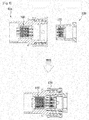
- Fig. 3 is a view illustrating a configuration of the first embodiment of the electromagnetic electrical connection device applied to the present invention.
- Fig. 4 is a view illustrating a configuration of the second embodiment of the electromagnetic electrical connection device applied to the present invention.
- the electromagnetic electrical connection device is configured such that, when magnetic substances (magnets) are joined to each other in a state in which terminals composed of an outer terminal and an inner terminal are separated from each other, the terminals are connected by magnetic force.
- the upper drawing shows a mutual separated state of the first and second electromagnetic electrical connection parts 100 and 100a.
- the lower drawing indicated by the arrow shows a coupled state of the first and second electromagnetic electrical connection parts 100 and 100a.
- the housing 115 and the outlet terminal operation portion 120 of the first electromagnetic electrical connection part 100 are located at one side in a non-operated state.
- the plug terminal operation portion 180 of the second electromagnetic electrical connection part 100a is located in a non-operated state.
- the main plug terminal 195 is connected to the connection terminal 113 and the connection terminal 113 comes into contact with the main outlet terminal 130 and the auxiliary outlet terminal 135, thereby enabling power to be applied to the electrical connection device.
- the spring 194 located at the spring operation groove 192 is compressed forward by properties of magnetic force during mutual contact of the parts, and the spring 193 located at the spring operation groove 191 is compressed rearward during mutual contact of the main plug terminal 195 and the connection terminal 113.
- the spring 136 located at the spring operation groove 122 is compressed forward during forward advance of the housing 115, and the spring 131 located at the spring operation groove 121 is compressed rearward during mutual contact of the main outlet terminal 130 and the connection terminal 113.
- the springs 193 and 131 serve to provide tension to the terminals and the springs 194 and 136 retreat while adjusting lengths thereof.
- first and second electromagnetic electrical connection parts 100 and 100a are again spaced apart from each other in the above state, the first and second electromagnetic electrical connection parts 100 and 100a are separated from each other as shown in the upper drawing and each component is returned to an initial state.
- the magnetic attenuation iron 117 included in the first electromagnetic electrical connection part 100 serve to prevent properties of magnetic force from being transferred to the electronic product.
- Fig. 3 shows the first embodiment without the spring 194 and the auxiliary plug terminal 196 of the second embodiment.
- the plug terminal operation portion 170 has a simple configuration and the first and second electromagnetic electrical connection parts 100 and 100a come into contact with each other by magnetic force.
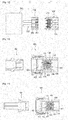
- the present embodiment is configured such that the above-mentioned second electromagnetic electrical connection part 100a selectively comes into contact with or is decoupled from a third electromagnetic electrical connection part 200.
- the third electromagnetic electrical connection part 200 includes an outlet body 210 which is formed, at one side thereof, with a locking protrusion 211 protruding therefrom such that the locking protrusion 211 is fitted into the locking groove 151 while being formed therein with terminal holes 212 at regular intervals such that a plurality of outlet terminals 213 are fitted into the terminal holes 212; and first and second magnets 215 and 216 which are respectively provided at a front end of one side of and inside the outlet body 210.
- the present invention may include and use a circular insulator and a magnet which are provided around each outlet terminal 213. This enables the flow of electric current through the magnet to be prevented by the insulator interposed between the outlet terminal 213 and the magnet.
- the third electromagnetic electrical connection part 200 coupled with the second electromagnetic electrical connection part 100a operates as follows.
- the first and second magnets 215 and 216 are respectively provided on an outer peripheral surface of the terminal hole 212 and an outer peripheral surface of the outlet terminal 213 so that the parts are closely connected by the magnet 161 of the plug body 150 and properties of magnetic force.
- the first, second, and third embodiments may be performed in various use states as shown in Figs. 6 to 10 .
- the present invention may also be used by being assembled using female and male waterproof couplers, female and male couplers, female and male lamp sockets, or the like.
- the electromagnetic electrical connection device includes a fourth electromagnetic electrical connection part 300 which is provided therein with auxiliary plug terminals 301 and magnets 303 and is provided, at an outer side thereof, with main plug terminals 302 protruding therefrom such that the main plug terminals 302 may be inserted into an outlet 350.
- the electromagnetic electrical connection device includes a fifth electromagnetic electrical connection part 310 provided therein with plug terminal operation portions 170.
- the electromagnetic electrical connection device includes a sixth electromagnetic electrical connection part 320 which is formed, at one side therein, with plug terminal operation portions 170 and is formed, at the other side therein, with plug terminal insertion holes 321.
- the electromagnetic electrical connection device is configured to be used in such a manner that the fourth and fifth electromagnetic electrical connection parts 300 and 310 are detachable from each other or the fourth and sixth electromagnetic electrical connection parts 300 and 320 are detachable from each other.
- Figs. 11 and 12 are views illustrating various use states of the fourth embodiment of the electromagnetic electrical connection device applied to the present invention.
- Fig. 11 shows a state in which the fourth and fifth electromagnetic electrical connection parts 300 and 310 are connected to the outlet 350 to be used.
- Fig. 12 shows a state in which the fourth and sixth electromagnetic electrical connection parts 300 and 320 are connected to the outlet 350 to be used.
- connection force is provided by mutual magnetic force between the magnet 303 and the magnet of the plug terminal operation portion 170.
- a female waterproof coupler 450 includes a seventh electromagnetic electrical connection part 400 therein such that a male waterproof coupler 451 is selectively detachable from the female waterproof coupler 450.
- the seventh electromagnetic electrical connection part 400 includes therein spring connectors 410, each of which is formed with a spring operation groove 411 such that a spring 413 is fitted into the spring operation groove 411.
- the seventh electromagnetic electrical connection part 400 includes an inclined surface 421 and an operation hole 412 which are formed at one side inside the spring connector 410.
- the seventh electromagnetic electrical connection part 400 includes a main outlet terminal 420 which is installed inside the spring connector 410 and is formed, at one side thereof, with a terminal tip portion 422.
- the seventh electromagnetic electrical connection part 400 includes a housing 430 which is provided at the other side inside the spring connector 410 and has a hole 431 therein.
- an auxiliary outlet terminal 440 is installed inside the housing 430.
- Figs. 13 and 14 are views illustrating various use states of the fifth embodiment of the electromagnetic electrical connection device applied to the present invention.
- Fig. 13 shows that the female waterproof coupler 450 is coupled to the male waterproof coupler 451
- Fig. 14 shows that a female lamp waterproof coupler 460 is coupled to a male lamp waterproof coupler 461.
- the terminal push the terminal tip portion 422.
- the main outlet terminal 420 is inserted into the hole 431 while being pushed toward the housing 430, and thus the main outlet terminal 420 is connected to the auxiliary outlet terminal 440 to enable power to be applied thereto.
- the spring 431 located at the spring operation groove 411 is compressed.
- the waterproof function may be maintained.
- airtightness may be maintained in a state in which the main outlet terminal 420 is not ejected outward at all by the inclined surface 421.
- Such a method may be applied to a coupler method or a connection method and an insertion method using the magnet.
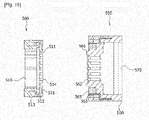
- the electromagnetic electrical connection device includes a eighth electromagnetic electrical connection part 500 which is detachably assembled to the product and a ninth electromagnetic electrical connection part 550 which is detachable from the eighth electromagnetic electrical connection part 500.
- the eighth electromagnetic electrical connection part 500 includes a body 510 in which a plurality of female terminals 514 and magnets 515 are installed therein at regular intervals, a pair of locking groove 511 and catching groove 512 are formed at one side thereof, and a catching piece 513 is formed inside the catching groove 512.
- the ninth electromagnetic electrical connection part 550 includes a body 560 in which a plurality of male terminals 562 and magnets 565 are installed therein at regular intervals, a pair of locking protrusion 561 and catching protrusion 563 are formed at one side thereof, and a connector 570 is installed behind the male terminals.
- the electromagnetic electrical connection device is configured such that the eighth electromagnetic electrical connection part 500, which is detachable from the ninth electromagnetic electrical connection part 550, is integrally or detachably installed to a variety of electronic devices or communication terminals (for example, mobile phones, PDAs, notebooks, mobile phone cases, etc.).
- electronic devices or communication terminals for example, mobile phones, PDAs, notebooks, mobile phone cases, etc.
- Fig. 15 is a view illustrating a configuration of the sixth embodiment of the electromagnetic electrical connection device applied to the present invention.
- Figs. 16 and 17 are views illustrating various use states of the seventh embodiment of the electromagnetic electrical connection device applied to the present invention.
- the eighth electromagnetic electrical connection part 500 may be fixedly installed to or selectively detachable from the electronic product.
- the locking protrusion 561 is fitted into the locking groove 511.
- the male terminal 562 is fitted into the female terminal 514 to enable power to be applied to the electromagnetic electrical connection device.
- the magnet of one side body 560 and the magnet of the other side body 560 generate attractive force by properties of magnetic force therebetween, and thus the eighth electromagnetic electrical connection part 500 and the ninth electromagnetic electrical connection part 550 are closely pressed against each other.
- the catching piece 513 of the body 510 is performed such that the eighth electromagnetic electrical connection part 500 may be securely installed to the electronic product, and the catching protrusion 563 of the body 560 is caught by the catching groove 512 and is performed such that the two bodies 560 and 510 may be closely installed to each other.
- the eighth electromagnetic electrical connection part 500 and the ninth electromagnetic electrical connection part 550 may be simply decoupled from each other when the above operation is reversely performed.
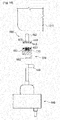
- the electromagnetic electrical connection device includes a tenth electromagnetic electrical connection part 600 and an eleventh electromagnetic electrical connection part 650 which is detachable, at one end thereof, from the tenth electromagnetic electrical connection part and is detachable, at the other end thereof, from a charger 660 provided with a jack 661.
- the tenth electromagnetic electrical connection part 600 includes a body 610 which is provided, at one side thereof, with a plurality of terminals 611 and a magnet 613 and is formed, at the other side thereof, with a jack 612 protruding therefrom such that the jack 612 is detachable from the electronic product.
- the eleventh electromagnetic electrical connection part 650 includes a body 651 which is provided, at one side thereof, with plug terminal operation portions 170 and a magnet 653 and is formed, at the other side thereof, with a jack insertion hole 652 from which a jack is detachable.
- Fig. 18 is a view illustrating a configuration of the eighth embodiment of the electromagnetic electrical connection device applied to the present invention.
- the tenth electromagnetic electrical connection part 600 is assembled to an electronic product 670, and the jack 612 is fitted into a hole of the electronic product.
- the eleventh electromagnetic electrical connection part 650 is coupled to the tenth electromagnetic electrical connection part 600, and the plug terminal operation portion 170 is connected to the terminal 611.
- the tenth electromagnetic electrical connection part and the eleventh electromagnetic electrical connection part may be closely pressed against each other by properties of the magnets 653 and 613.
- the eleventh electromagnetic electrical connection part 650 is connected, at one end thereof, with the charger 660 such that the jack 661 is fitted into the jack insertion hole 652. As a result, power of the charger may be applied to the electronic product.
- the technical idea of an improved structure of an electromagnetic electrical connection device according to the present invention can repeatedly execute the same results, and can in particular contribute to the development of the industry to promote the development of the technology by carrying out the present invention.
Abstract
Description
- The present invention relates to an improved structure of an electromagnetic electrical connection device capable of being applied to a variety of electronic products (for example, plugs, outlets, typical or waterproof connectors, sockets, jacks, adaptors, etc.) so as to be widely used. More particularly, the present invention allows electrical or signal connection to be smoothly performed using properties of magnetic force so as to conveniently provide electrical connection and disconnection while providing effects such as noise isolation, stability, and waterproofing functions during connection of the electrical connection device, thereby significantly improving quality and reliability of the product to present a good image to a user which is a consumer.
- The present invention is to further improve Korean Patent Application No.
2011-0002404 - As well known in the art, power is connected to an outlet as an interior wiring connector so as to be supplied to a variety of electronic products requiring power. A plug is installed to an end of a cable of an electronic product such that power is shut off and the cable is arranged when the plug is decoupled from the outlet, thereby easily transporting and storing the electronic product. Power is supplied to the electronic product when the plug is connected to the outlet, and thus the electronic product operates.
- In a plug and an outlet as conventional power connection mechanisms related to such an art, as shown in
Fig. 1 , aplug 40 is installed to acable 41 joined to an electronic product andplug terminals 40a protrude from an end of theplug 40. Anoutlet 50 is installed such that theplug terminals 40a of theplug 40 are inserted into theoutlet 50. Theoutlet 50 is formed, at the front thereof, with ahole 51 andterminal insertion grooves 52 are symmetrically formed on a bottom surface of thehole 51. - In the conventional plug and outlet, the cable is connected, at one end thereof, to a power supply of the electronic product while being provided, at the other end thereof, with the
plug 40, and theplug terminals 40a protrude from the end of theplug 40. When theplug terminals 40a of theplug 40 are inserted into theterminal insertion grooves 52 formed in thehole 51 of theoutlet 50, theplug terminals 40a are electrically connected to connection pieces which are installed inside theterminal insertion grooves 52 to be connected to power, thereby supplying the power to the electronic product. - The
plug 40 and theoutlet 50 as the power connection mechanisms which are inserted and fastened as described above are inconvenient in that, when theplug 40 is fitted into theoutlet 50 in the dark and narrow place, theplug terminals 40a of theplug 40 are exactly inserted into theterminal insertion grooves 52 of theoutlet 50. - In addition, when the
plug terminals 40a of theplug 40 are tightly inserted into theterminal insertion grooves 52 of theoutlet 50, large force is required to decouple theplug 40. Furthermore, since there is a need to pull the cable joined to theplug 40 when theplug 40 is well not decoupled from theoutlet 50, a short circuit may be generated at a connection part between the plug and the cable. - Meanwhile, the terminal insertion grooves 52 into which the
plug terminals 40a of theplug 40 are inserted in thehole 51 of theoutlet 50 are always opened. Accordingly, when children insert conductive objects into theterminal insertion grooves 52 due to curiosity, an electric shock accident may be caused. In addition, when foreign matters are inserted into theterminal insertion grooves 52, theplug terminals 40a of theplug 40 may not be inserted into theterminal insertion grooves 52. - The solution of the above-mentioned problems is disclosed in Korean Unexamined Patent Application Publication No.
2002-0080766 2001-0020525 - That is, the above relate art is constituted as shown in
Fig. 2 . A plug insertion portion 4 having a groove shape is formed in acase 3 of anoutlet 2, and a plurality of power terminals 5 and 5' are formed on the plane within the groove of the plug insertion portion 4. The plug insertion portion 4 is provided therein withfirst magnets 6 and 6' to fix a plug 1 by magnetic force, and the plug 1 is provided withsecond magnets 7 and 7' to fix the plug 1 to the plug insertion portion 4 by attractive force acting on positions corresponding to thefirst magnets 6 and 6'. - In addition, the plug 1 is formed with a plurality of
plug terminals 8 and 8' on the contact surface of the plug 1 so as to correspond to the plural power terminals 5 and 5' formed within the plug insertion portion 4. Thecase 3 of theoutlet 2 is formed therein withsafety switches 10 and 10' which turn on/off power by magnetic force, and the plug 1 is formed with third magnets 9 and 9' to operate thesafety switches 10 and 10' by magnetic force. In this case, thesafety switches 10 and 10' include first contact 11 and 11' connected to the power terminals 5 and 5',second contacts 12 and 12' connected topower supply lines 20 and 20', switchportions 13 and 13' which move by magnetic force of the third magnets 9 and 9' and connect the first contact 11 and 11' to thesecond contacts 12 and 12', andelastic bodies 14 and 14' which are elastic restoring means to return theswitch portions 13 and 13' to original positions when the magnetic force of the third magnets 9 and 9' do not affected thereto, respectively. In this case, theswitch portions 13 and 13' are ferromagnetic bodies and conductive substances, and are configured to be moved by attractive force acting between the third magnets 9 and 9' and theswitch portions 13 and 13'. - However, the
switch portions 13 and 13' may also be moved by installing magnets to theswitch portions 13 and 13' such that repulsive force acts between the third magnets 9 and 9' and theswitch portions 13 and 13'. In addition, in order to easily adjust contact positions between the power terminals 5 and 5' and theplug terminals 8 and 8', the related art is configured such that the contact positions may be exactly adjusted by attractive force by forming concave-convex portions at the installation positions of thefirst magnets 6 and 6', thesecond magnets 7 and 7', and the third magnets 9 and 9'. However, the related art may also be configured such that coupling directions and positions between the power terminals 5 and 5' and theplug terminals 8 and 8' may be exactly adjusted by forming separate concave-convex portions in addition to such a configuration. - Accordingly, if the plug 1 is inserted into the plug insertion portion 4 of the
outlet 2, attractive force acts between thefirst magnets 6 and 6' formed in theoutlet 2 and thesecond magnets 7 and 7' formed in the plug 1. Consequently, the plug 1 may be inserted into and simply attached to the plug insertion portion 4 of theoutlet 2 without separation from each other. Thus, the power terminals 5 and 5' of theoutlet 2 come into contact with theplug terminals 8 and 8' of the plug 1, thereby forming a circuit. - In addition, the power terminals 5 and 5' come into contact with the
plug terminals 8 and 8' and theswitch portions 13 and 13' of thesafety switches 10 and 10' are moved by attractive force of the third magnets 9 and 9' so as to connect the first contacts 11 and 11' to thesecond contacts 12 and 12', with the consequence that thepower supply lines 20 and 20' and the power terminals 5 and 5' are connected to each other. Consequently, the circuit is formed such that power is supplied to the power terminals 5 and 5' and is supplied to the electronic product through theplug terminals 8 and 8' coming into contact with the power terminals 5 and 5'. - Meanwhile, in a case of decoupling the plug 1 from the plug insertion portion 4 of the
outlet 2, the plug 1 and the plug insertion portion 4 may be easily separated from each other even when large force is not applied thereto only because of coming into contact with each other by attractive force of the magnets. When the plug 1 is decoupled from the plug insertion portion 4 of theoutlet 2, the power terminals 5 and 5' and theplug terminals 8 and 8' are separated from each other and the attractive force of the third magnets 9 and 9' which allows theswitch portions 13 and 13' of thesafety switches 10 and 10' to be moved is removed. As a result, as theswitch portions 13 and 13' are returned to original positions by theelastic bodies 14 and 14', the connection between the first contact 11 and 11' and thesecond contacts 12 and 12' is disconnected so that power is not supplied to the power terminals 5 and 5'. Accordingly, even if the power terminals 5 and 5' are touched by a user's fingers or come into contact with chopsticks or the like, electrical accidents may be prevented in advance because the power is not supplied thereto. - However, the above related art has the following several problems.
- That is, the above related art is pointed out as a major problem in that it may not be used in other electronic products in addition to having simple functions such as the plug and the outlet.
- Particularly, the above related art has a serious problem in that it may not be possible to provide various effects such as noise isolation, stability, and waterproofing functions during connection of an electrical connection device.
- Accordingly, the present invention has been made in view of the above-mentioned problems, and is to provide an improved structure of an electromagnetic electrical connection device capable of achieving the following objects: a first object of the present invention is to include first to eleventh electromagnetic electrical connection parts; a second object thereof is to enable electrical or signal connection to be smoothly performed using properties of magnetic force so as to conveniently provide electrical connection and disconnection; a third object thereof is to provide effects such as noise isolation, stability, and waterproofing functions during connection of the electrical connection device; and a fourth object thereof is to significantly improve quality and reliability of a product to present a good image to a user which is a consumer.
- In order to achieve such objects, the present invention provides an improved structure of an electromagnetic electrical connection device including first and second electromagnetic electrical connection parts which realize noise isolation, stability, and waterproofing functions during electrical connection of the electrical connection device of an electronic product by magnetic force, wherein the first and second electromagnetic electrical connection parts include an outlet body which is fixedly installed to the product and a plug body which is selectively detachable from the outlet body, respectively.
- As is apparent from the above description, the present invention includes first to eleventh electromagnetic electrical connection parts.
- The present invention according to such a technical configuration enables electrical or signal connection to be smoothly performed using properties of magnetic force so as to conveniently provide electrical connection and disconnection.
- In addition, the present invention may provide effects such as noise isolation, stability, and waterproofing functions during connection of an electrical connection device.
- The present invention may significantly improve quality and reliability of a product to present a good image to a user which is a consumer by the above effects.
- Additional advantages, objects, and features of the invention will be set forth in part in the description which follows and in part will become apparent to those having ordinary skill in the art upon examination of the following or may be learned from practice of the invention.
- The above and other objects, features and other advantages of the present invention will be more clearly understood from the following detailed description taken in conjunction with the accompanying drawings.
-
Fig. 1 is a perspective view illustrating a plug and an outlet which are conventional power connection mechanisms. -
Fig. 2 is a cross-sectional view illustrating conventional power connection mechanisms using magnets. -
Fig. 3 is a view illustrating a configuration of a first embodiment of an electromagnetic electrical connection device applied to the present invention. -
Fig. 4 is a view illustrating a configuration of a second embodiment of the electromagnetic electrical connection device applied to the present invention. -
Fig. 5 is a view illustrating a configuration of a third embodiment of the electromagnetic electrical connection device applied to the present invention. -
Fig. 6 is a view illustrating a state using the electromagnetic electrical connection device applied to the present invention. -
Fig. 7 is a view illustrating a state using the electromagnetic electrical connection device applied to the present invention. -
Fig. 8 is a view illustrating a state using the electromagnetic electrical connection device applied to the present invention. -
Fig. 9 is a view illustrating a state using the electromagnetic electrical connection device applied to the present invention. -
Fig. 10 is a view illustrating a state using the electromagnetic electrical connection device applied to the present invention. -
Fig. 11 is a view illustrating a use state of a fourth embodiment of the electromagnetic electrical connection device applied to the present invention. -
Fig. 12 is a view illustrating the use state of the fourth embodiment of the electromagnetic electrical connection device applied to the present invention. -
Fig. 13 is a view illustrating a use state of a fifth embodiment of the electromagnetic electrical connection device applied to the present invention. -
Fig. 14 is a view illustrating the use state of the fifth embodiment of the electromagnetic electrical connection device applied to the present invention. -
Fig. 15 is a view illustrating a configuration of a sixth embodiment of the electromagnetic electrical connection device applied to the present invention. -
Fig. 16 is a view illustrating a use state of a seventh embodiment of the electromagnetic electrical connection device applied to the present invention. -
Fig. 17 is a view illustrating the use state of the seventh embodiment of the electromagnetic electrical connection device applied to the present invention. -
Fig. 18 is a view illustrating a configuration of an eighth embodiment of the electromagnetic electrical connection device applied to the present invention. - Reference will now be made in detail to embodiments of the present invention, examples of which are illustrated in the accompanying drawings.
- An improved structure of an electromagnetic electrical connection device applied to the present invention is configured as shown in
Figs. 3 to 18 . - Hereinafter, in the description of the present invention, if it is determined that the detailed description for the related known function or configuration can unnecessarily obscure the gist of the present invention, the detailed description thereof will be omitted.
- In addition, terms to be described later are terms defined in consideration of functions of the present invention, and these may vary with the intention or practice of a user. Therefore, such terms should be defined based on the entire content disclosed herein.
- First, a description will be given of first and second embodiments of an electromagnetic electrical connection device according to the present invention.
- That is, an electromagnetic electrical connection device includes first and second electromagnetic
electrical connection parts electrical connection parts outlet body 110 which is fixedly installed to the product and aplug body 150 which is selectively detachable from theoutlet body 110, respectively. - Particularly, the
outlet body 110 is configured as follows. - That is, the
outlet body 110 includes an inneroperation space portion 111 and a plurality ofconnection terminals 113 which are arranged at regular intervals on oneside locking protrusion 112. - The
outlet body 110 includes ahousing 115 which is installed inside theoperation space portion 111 to selectively slide. - In addition, the
outlet body 110 includes amagnet 116 which is fixedly installed to thehousing 115. - The
outlet body 110 includes a plurality of outletterminal operation portions 120 which are installed at regular intervals to thehousing 115 such that the outletterminal operation portions 120 come into contact with or are decoupled from the connection terminals. - Furthermore, the
housing 115 is provided with amagnetic attenuation iron 117 to prevent magnetic properties of themagnet 116 from being transferred to the product. - Meanwhile, each of the outlet
terminal operation portions 120 is configured as follows. - That is, the outlet
terminal operation portion 120 includes aspring connector 120a, opposite ends of which are respectively formed withspring operation grooves - The outlet
terminal operation portion 120 includes amain outlet terminal 130 and anauxiliary outlet terminal 135 which are respectively fitted into thespring operation grooves - In addition, the outlet
terminal operation portion 120 includes aspring 131 which is installed inside themain outlet terminal 130. - The outlet
terminal operation portion 120 includes aspring 136 which is installed on an intermediate outer peripheral surface of theauxiliary outlet terminal 135. - Meanwhile, the
plug body 150 is configured as follows. - That is, the
plug body 150 includes ahousing 160 which is fixedly installed to aninner locking groove 151. - In addition, the
plug body 150 includes a magnet or aniron 161 which is fixedly installed to thehousing 160. - The
plug body 150 includes plugterminal operation portions housing 160 such that the plugterminal operation portions connection terminals 113. - Particularly, the plug
terminal operation portion 170 includes aspring connector 190 in which amain plug terminal 195 is installed at a front end thereof and aspring 193 is fitted into an innerspring operation groove 191. - In addition, the plug
terminal operation portion 180 includes aspring connector 190 in which amain plug terminal 195 is installed at a front end thereof and aspring 193 is fitted into an innerspring operation groove 191; and anauxiliary plug terminal 196 which is provided at one end of thespring connector 190 and in which aspring 194 is fitted into an innerspring operation groove 192. - Hereinafter, operation effects of the first and second embodiments of the electromagnetic electrical connection device according to the present invention having the above-mentioned configure will be described.
-
Fig. 3 is a view illustrating a configuration of the first embodiment of the electromagnetic electrical connection device applied to the present invention.Fig. 4 is a view illustrating a configuration of the second embodiment of the electromagnetic electrical connection device applied to the present invention. The electromagnetic electrical connection device is configured such that, when magnetic substances (magnets) are joined to each other in a state in which terminals composed of an outer terminal and an inner terminal are separated from each other, the terminals are connected by magnetic force. - First, referring to
Fig. 4 , the second embodiment of the present invention will be described prior to the first embodiment. - The upper drawing shows a mutual separated state of the first and second electromagnetic
electrical connection parts electrical connection parts - In the upper drawing, the
housing 115 and the outletterminal operation portion 120 of the first electromagneticelectrical connection part 100 are located at one side in a non-operated state. The plugterminal operation portion 180 of the second electromagneticelectrical connection part 100a is located in a non-operated state. - In such a state, when the second electromagnetic
electrical connection part 100a approach the first electromagneticelectrical connection part 100, the parts come into close contact with each other by magnetic force as shown in the lower drawing. - That is, when the locking
protrusion 112 is fitted into the lockinggroove 151, the parts are closely pressed against each other by magnetic properties of themagnets main plug terminal 195 is connected to theconnection terminal 113 and theconnection terminal 113 comes into contact with themain outlet terminal 130 and theauxiliary outlet terminal 135, thereby enabling power to be applied to the electrical connection device. - In this case, the
spring 194 located at thespring operation groove 192 is compressed forward by properties of magnetic force during mutual contact of the parts, and thespring 193 located at thespring operation groove 191 is compressed rearward during mutual contact of themain plug terminal 195 and theconnection terminal 113. - In addition, the
spring 136 located at thespring operation groove 122 is compressed forward during forward advance of thehousing 115, and thespring 131 located at thespring operation groove 121 is compressed rearward during mutual contact of themain outlet terminal 130 and theconnection terminal 113. - As a result, the
springs springs - Of course, when the first and second electromagnetic
electrical connection parts electrical connection parts - In addition, the
magnetic attenuation iron 117 included in the first electromagneticelectrical connection part 100 serve to prevent properties of magnetic force from being transferred to the electronic product. - Meanwhile,
Fig. 3 shows the first embodiment without thespring 194 and theauxiliary plug terminal 196 of the second embodiment. In the first embodiment, the plugterminal operation portion 170 has a simple configuration and the first and second electromagneticelectrical connection parts - In addition, a description will be given of third embodiment of the electromagnetic electrical connection device according to the present invention.
- That is, the present embodiment is configured such that the above-mentioned second electromagnetic
electrical connection part 100a selectively comes into contact with or is decoupled from a third electromagneticelectrical connection part 200. - In this case, the third electromagnetic
electrical connection part 200 includes anoutlet body 210 which is formed, at one side thereof, with a lockingprotrusion 211 protruding therefrom such that the lockingprotrusion 211 is fitted into the lockinggroove 151 while being formed therein withterminal holes 212 at regular intervals such that a plurality ofoutlet terminals 213 are fitted into the terminal holes 212; and first andsecond magnets outlet body 210. - The present invention may include and use a circular insulator and a magnet which are provided around each
outlet terminal 213. This enables the flow of electric current through the magnet to be prevented by the insulator interposed between theoutlet terminal 213 and the magnet. - Hereinafter, operation effects of the third embodiment of the electromagnetic electrical connection device according to the present invention having the above-mentioned configure will be described.
- First, since the second electromagnetic
electrical connection part 100a operates in the same manner as the above-mentioned embodiments, the detailed description thereof will be omitted herein. - However, the third electromagnetic
electrical connection part 200 coupled with the second electromagneticelectrical connection part 100a operates as follows. - That is, when the second and third electromagnetic
electrical connection parts outlet terminal 213 while themain plug terminal 195 is fitted into theterminal hole 212. - In this case, the first and
second magnets terminal hole 212 and an outer peripheral surface of theoutlet terminal 213 so that the parts are closely connected by themagnet 161 of theplug body 150 and properties of magnetic force. - Of course, when the parts are again spaced apart from each other in the above state, all components are returned to an initial state. The other remaining operation effects are the same as the above-mentioned embodiments.
- The first, second, and third embodiments may be performed in various use states as shown in
Figs. 6 to 10 . For example, the present invention may also be used by being assembled using female and male waterproof couplers, female and male couplers, female and male lamp sockets, or the like. - In addition, a description will be given of fourth embodiment of the electromagnetic electrical connection device according to the present invention.
- That is, the electromagnetic electrical connection device includes a fourth electromagnetic
electrical connection part 300 which is provided therein withauxiliary plug terminals 301 andmagnets 303 and is provided, at an outer side thereof, withmain plug terminals 302 protruding therefrom such that themain plug terminals 302 may be inserted into anoutlet 350. - The electromagnetic electrical connection device includes a fifth electromagnetic
electrical connection part 310 provided therein with plugterminal operation portions 170. - In addition, the electromagnetic electrical connection device includes a sixth electromagnetic
electrical connection part 320 which is formed, at one side therein, with plugterminal operation portions 170 and is formed, at the other side therein, with plug terminal insertion holes 321. The electromagnetic electrical connection device is configured to be used in such a manner that the fourth and fifth electromagneticelectrical connection parts electrical connection parts - Hereinafter, operation effects of the fourth embodiment of the electromagnetic electrical connection device according to the present invention having the above-mentioned configure will be described.
-
Figs. 11 and12 are views illustrating various use states of the fourth embodiment of the electromagnetic electrical connection device applied to the present invention. - That is,
Fig. 11 shows a state in which the fourth and fifth electromagneticelectrical connection parts outlet 350 to be used.Fig. 12 shows a state in which the fourth and sixth electromagneticelectrical connection parts outlet 350 to be used. - In more detail, when the plug
terminal operation portion 170 of the fifth electromagneticelectrical connection part 310 comes into contact with theauxiliary plug terminal 301, power is applied to themain plug terminal 302. In this process, connection force is provided by mutual magnetic force between themagnet 303 and the magnet of the plugterminal operation portion 170. - In addition, when the plug
terminal operation portion 170 of the sixth electromagneticelectrical connection part 320 comes into contact with theauxiliary plug terminal 301, power is applied to themain plug terminal 302. The remaining operation is the same as the above-mentioned operation. Thereafter, when the two components are separated from each other, the components are naturally returned to an initial state. - In addition, a description will be given of fifth embodiment of the electromagnetic electrical connection device according to the present invention.
- That is, a female
waterproof coupler 450 includes a seventh electromagneticelectrical connection part 400 therein such that a malewaterproof coupler 451 is selectively detachable from the femalewaterproof coupler 450. The seventh electromagneticelectrical connection part 400 includes thereinspring connectors 410, each of which is formed with aspring operation groove 411 such that aspring 413 is fitted into thespring operation groove 411. - The seventh electromagnetic
electrical connection part 400 includes aninclined surface 421 and anoperation hole 412 which are formed at one side inside thespring connector 410. - In addition, the seventh electromagnetic
electrical connection part 400 includes amain outlet terminal 420 which is installed inside thespring connector 410 and is formed, at one side thereof, with aterminal tip portion 422. - The seventh electromagnetic
electrical connection part 400 includes ahousing 430 which is provided at the other side inside thespring connector 410 and has ahole 431 therein. - Furthermore, an
auxiliary outlet terminal 440 is installed inside thehousing 430. - Hereinafter, operation effects of the fifth embodiment of the electromagnetic electrical connection device according to the present invention having the above-mentioned configure will be described.
-
Figs. 13 and 14 are views illustrating various use states of the fifth embodiment of the electromagnetic electrical connection device applied to the present invention. In particular,Fig. 13 shows that the femalewaterproof coupler 450 is coupled to the malewaterproof coupler 451, andFig. 14 shows that a female lamp waterproof coupler 460 is coupled to a male lampwaterproof coupler 461. - In more detail, in the drawing of illustrating a state before the seventh electromagnetic
electrical connection part 400 operates, when the male waterproof coupler or the male lamp waterproof coupler is inserted into the female coupler, the terminal push theterminal tip portion 422. Accordingly, themain outlet terminal 420 is inserted into thehole 431 while being pushed toward thehousing 430, and thus themain outlet terminal 420 is connected to theauxiliary outlet terminal 440 to enable power to be applied thereto. In this process, thespring 431 located at thespring operation groove 411 is compressed. Particularly, since theterminal tip portion 422 is not deviated from theoperation hole 412 even if theterminal tip portion 422 is pushed, the waterproof function may be maintained. Of course, when the couplers are separated from each other and theterminal tip portion 422 is returned to an original state, airtightness may be maintained in a state in which themain outlet terminal 420 is not ejected outward at all by theinclined surface 421. - Such a method may be applied to a coupler method or a connection method and an insertion method using the magnet.
- In addition, a description will be given of sixth and seventh embodiments of the electromagnetic electrical connection device according to the present invention.
- That is, the electromagnetic electrical connection device includes a eighth electromagnetic
electrical connection part 500 which is detachably assembled to the product and a ninth electromagneticelectrical connection part 550 which is detachable from the eighth electromagneticelectrical connection part 500. The eighth electromagneticelectrical connection part 500 includes abody 510 in which a plurality offemale terminals 514 andmagnets 515 are installed therein at regular intervals, a pair of lockinggroove 511 and catchinggroove 512 are formed at one side thereof, and a catchingpiece 513 is formed inside the catchinggroove 512. - The ninth electromagnetic
electrical connection part 550 includes abody 560 in which a plurality ofmale terminals 562 andmagnets 565 are installed therein at regular intervals, a pair of lockingprotrusion 561 and catchingprotrusion 563 are formed at one side thereof, and aconnector 570 is installed behind the male terminals. - In addition, the electromagnetic electrical connection device is configured such that the eighth electromagnetic
electrical connection part 500, which is detachable from the ninth electromagneticelectrical connection part 550, is integrally or detachably installed to a variety of electronic devices or communication terminals (for example, mobile phones, PDAs, notebooks, mobile phone cases, etc.). - Hereinafter, operation effects of the sixth and seventh embodiments of the electromagnetic electrical connection device according to the present invention having the above-mentioned configure will be described.
-
Fig. 15 is a view illustrating a configuration of the sixth embodiment of the electromagnetic electrical connection device applied to the present invention.Figs. 16 and17 are views illustrating various use states of the seventh embodiment of the electromagnetic electrical connection device applied to the present invention. - In more detail, the eighth electromagnetic
electrical connection part 500 may be fixedly installed to or selectively detachable from the electronic product. - When the ninth electromagnetic
electrical connection part 550 is coupled to the eighth electromagneticelectrical connection part 500, the lockingprotrusion 561 is fitted into the lockinggroove 511. In this process, themale terminal 562 is fitted into thefemale terminal 514 to enable power to be applied to the electromagnetic electrical connection device. The magnet of oneside body 560 and the magnet of theother side body 560 generate attractive force by properties of magnetic force therebetween, and thus the eighth electromagneticelectrical connection part 500 and the ninth electromagneticelectrical connection part 550 are closely pressed against each other. - Particularly, the catching
piece 513 of thebody 510 is performed such that the eighth electromagneticelectrical connection part 500 may be securely installed to the electronic product, and the catchingprotrusion 563 of thebody 560 is caught by the catchinggroove 512 and is performed such that the twobodies - Of course, the eighth electromagnetic
electrical connection part 500 and the ninth electromagneticelectrical connection part 550 may be simply decoupled from each other when the above operation is reversely performed. - In addition, a description will be given of eighth embodiment of the electromagnetic electrical connection device according to the present invention.
- That is, the electromagnetic electrical connection device includes a tenth electromagnetic
electrical connection part 600 and an eleventh electromagneticelectrical connection part 650 which is detachable, at one end thereof, from the tenth electromagnetic electrical connection part and is detachable, at the other end thereof, from acharger 660 provided with ajack 661. The tenth electromagneticelectrical connection part 600 includes abody 610 which is provided, at one side thereof, with a plurality ofterminals 611 and amagnet 613 and is formed, at the other side thereof, with ajack 612 protruding therefrom such that thejack 612 is detachable from the electronic product. - In addition, the eleventh electromagnetic
electrical connection part 650 includes abody 651 which is provided, at one side thereof, with plugterminal operation portions 170 and amagnet 653 and is formed, at the other side thereof, with ajack insertion hole 652 from which a jack is detachable. - Hereinafter, operation effects of the eighth embodiment of the electromagnetic electrical connection device according to the present invention having the above-mentioned configure will be described.
-
Fig. 18 is a view illustrating a configuration of the eighth embodiment of the electromagnetic electrical connection device applied to the present invention. - In more detail, the tenth electromagnetic
electrical connection part 600 is assembled to anelectronic product 670, and thejack 612 is fitted into a hole of the electronic product. - The eleventh electromagnetic
electrical connection part 650 is coupled to the tenth electromagneticelectrical connection part 600, and the plugterminal operation portion 170 is connected to the terminal 611. In this case, the tenth electromagnetic electrical connection part and the eleventh electromagnetic electrical connection part may be closely pressed against each other by properties of themagnets electrical connection part 650 is connected, at one end thereof, with thecharger 660 such that thejack 661 is fitted into thejack insertion hole 652. As a result, power of the charger may be applied to the electronic product. - Of course, the components may be simply decoupled from each other when the above operation is reversely performed.
- Meanwhile, the present invention can be modified in various ways and take many different forms, in applying the above configuration.
- Although the present invention has been described with respect to the illustrative embodiments, it will be apparent to those skilled in the art that various variations and modifications may be made without departing from the spirit and scope of the invention as defined in the following claims. Various embodiments have been described in the best mode for carrying out the invention.
- In fact, the technical idea of an improved structure of an electromagnetic electrical connection device according to the present invention can repeatedly execute the same results, and can in particular contribute to the development of the industry to promote the development of the technology by carrying out the present invention.
Claims (12)
- An improved structure of an electromagnetic electrical connection device including first and second electromagnetic electrical connection parts (100 and 100a) which realize noise isolation, stability, and waterproofing functions during electrical connection of the electrical connection device of an electronic product by magnetic force, the first and second electromagnetic electrical connection parts (100 and 100a) respectively including an outlet body (110) which is fixedly installed to the product and a plug body (150) which is selectively detachable from the outlet body (110), the second electromagnetic electrical connection part (100a) selectively coming into contact with or being decoupled from a third electromagnetic electrical connection part (200),
wherein the outlet body (110) comprises:an inner operation space portion (111), and a plurality of connection terminals (113) which are arranged at regular intervals on one side locking protrusion (112);a housing (115) which is installed inside the operation space portion (111) to selectively slide;a magnet (116) which is fixedly installed to the housing (115); anda plurality of outlet terminal operation portions (120) which are installed at regular intervals to the housing (115) such that the outlet terminal operation portions (120) come into contact with or are decoupled from the connection terminals. - The improved structure of an electromagnetic electrical connection device according to claim 1, wherein the housing (115) further comprises a magnetic attenuation iron (117) to prevent magnetic properties of the magnet (116) from being transferred to the product.
- The improved structure of an electromagnetic electrical connection device according to claim 1, wherein each of the outlet terminal operation portions (120) comprises:a spring connector (120a), opposite ends of which are respectively formed with spring operation grooves (121 and 122);a main outlet terminal (130) and an auxiliary outlet terminal (135) which are respectively fitted into the spring operation grooves (121 and 122);a spring (131) which is installed inside the main outlet terminal (130); anda spring (136) which is installed on an intermediate outer peripheral surface of the auxiliary outlet terminal (135).
- The improved structure of an electromagnetic electrical connection device according to claim 1, wherein the plug body (150) comprises:a housing (160) which is fixedly installed to an inner locking groove (151) a magnet or an iron (161) which is fixedly installed to the housing (160); andplug terminal operation portions (170 and 180) which are fixedly installed at regular intervals to the housing (160) such that the plug terminal operation portions (170 and 180) selectively come into contact with or are decoupled from the connection terminals (113).
- The improved structure of an electromagnetic electrical connection device according to claim 4, wherein the plug terminal operation portion (170) comprises a spring connector (190) in which a main plug terminal (195) is installed at a front end thereof and a spring (193) is fitted into an inner spring operation groove (191).
- The improved structure of an electromagnetic electrical connection device according to claim 4, wherein the plug terminal operation portion (180) comprises:a spring connector (190) in which a main plug terminal (195) is installed at a front end thereof and a spring (193) is fitted into an inner spring operation groove (191); andan auxiliary plug terminal (196) which is provided at one end of the spring connector (190) and in which a spring (194) is fitted into an inner spring operation groove (192).
- The improved structure of an electromagnetic electrical connection device according to claim 1, wherein the third electromagnetic electrical connection part (200) comprises:an outlet body (210) which is formed, at one side thereof, with a locking protrusion (211) protruding therefrom such that the locking protrusion (211) is fitted into a locking groove (151) while being formed therein with terminal holes (212) at regular intervals such that a plurality of outlet terminals (213) are fitted into the terminal holes (212); andfirst and second magnets (215 and 216) which are respectively provided at a front end of one side of and inside the outlet body (210), or the third electromagnetic electrical connection part (200) comprising a circular insulator and a magnet which are provided around each outlet terminal (213) to use the same.
- The improved structure of an electromagnetic electrical connection device according to claim 1,
wherein the electromagnetic electrical connection device comprises:a fourth electromagnetic electrical connection part (300) which is provided therein with an auxiliary plug terminal (301) and a magnet (303) and is provided, at an outer side thereof, with a main plug terminal (302) protruding therefrom such that the main plug terminal (302) is capable of being inserted into an outlet (350);a fifth electromagnetic electrical connection part (310) which is provided therein with a plug terminal operation portion (170); anda sixth electromagnetic electrical connection part (320) which is formed, at one side therein, with a plug terminal operation portion (170) and is formed, at the other side therein, with a plug terminal insertion hole (321), andwherein the electromagnetic electrical connection device is configured to be used in such a manner that the fourth and fifth electromagnetic electrical connection parts (300 and 310) are detachable from each other or the fourth and sixth electromagnetic electrical connection parts (300 and 320) are detachable from each other. - The improved structure of an electromagnetic electrical connection device according to claim 1,
wherein in the electromagnetic electrical connection device, a female waterproof coupler (450) comprises a seventh electromagnetic electrical connection part (400) therein such that a male waterproof coupler (451) is selectively detachable from the female waterproof coupler (450), and wherein the seventh electromagnetic electrical connection part (400) comprises:a spring connector (410) formed therein with a spring operation groove (411) into which a spring (413) is fitted;an inclined surface (421) and an operation hole (412) which are formed at one side inside the spring connector (410);a main outlet terminal (420) which is installed inside the spring connector (410) and is formed, at one side thereof, with a terminal tip portion (422);a housing (430) which is provided at the other side inside the spring connector (410) and has a hole (431) therein; andan auxiliary outlet terminal (440) installed inside the housing (430). - The improved structure of an electromagnetic electrical connection device according to claim 1, wherein:the electromagnetic electrical connection device comprises a eighth electromagnetic electrical connection part (500) which is detachably assembled to the product and a ninth electromagnetic electrical connection part (550) which is detachable from the eighth electromagnetic electrical connection part (500);the eighth electromagnetic electrical connection part (500) comprises a body (510) in which a plurality of female terminals (514) and magnets (515) are installed therein at regular intervals, a pair of locking groove (511) and catching groove (512) are formed at one side thereof, and a catching piece (513) is formed inside the catching groove (512); andthe ninth electromagnetic electrical connection part (550) comprises a body (560) in which a plurality of male terminals (562) and magnets (565) are installed therein at regular intervals, a pair of locking protrusion (561) and catching protrusion (563) are formed at one side thereof, and a connector (570) is installed behind the male terminals.
- The improved structure of an electromagnetic electrical connection device according to claim 10, wherein the eighth electromagnetic electrical connection part (500), which is detachable from the ninth electromagnetic electrical connection part (550), is integrally or detachably installed to a communication terminal (for example, a mobile phone, a PDA, a notebook, a mobile phone case, or the like).
- The improved structure of an electromagnetic electrical connection device according to claim 1, wherein:the electromagnetic electrical connection device comprises a tenth electromagnetic electrical connection part (600) and an eleventh electromagnetic electrical connection part (650) which is detachable, at one end thereof, from the tenth electromagnetic electrical connection part and is detachable, at the other end thereof, from a charger (660) provided with a jack (661);the tenth electromagnetic electrical connection part (600) comprises a body (610) which is provided, at one side thereof, with a plurality of terminals (611) and a magnet (613) and is formed, at the other side thereof, with a jack (612) protruding therefrom such that the jack (612) is detachable from the electronic product; andthe eleventh electromagnetic electrical connection part (650) comprises a body (651) which is provided, at one side thereof, with a plug terminal operation portion (170) and a magnet (653) and is formed, at the other side thereof, with a jack insertion hole (652) from which a jack is detachable.
Applications Claiming Priority (2)
| Application Number | Priority Date | Filing Date | Title |
|---|---|---|---|
| KR1020110039441A KR101103028B1 (en) | 2011-04-27 | 2011-04-27 | A improved structure of electromagnetism electricity connection device |
| PCT/KR2012/003219 WO2012148178A2 (en) | 2011-04-27 | 2012-04-26 | Improved structure of electromagnetic electrical connection device |
Publications (2)
| Publication Number | Publication Date |
|---|---|
| EP2704265A2 true EP2704265A2 (en) | 2014-03-05 |
| EP2704265A4 EP2704265A4 (en) | 2015-04-15 |
Family
ID=45613813
Family Applications (1)
| Application Number | Title | Priority Date | Filing Date |
|---|---|---|---|
| EP12776818.2A Withdrawn EP2704265A4 (en) | 2011-04-27 | 2012-04-26 | Improved structure of electromagnetic electrical connection device |
Country Status (6)
| Country | Link |
|---|---|
| US (1) | US9077105B2 (en) |
| EP (1) | EP2704265A4 (en) |
| JP (1) | JP6014894B2 (en) |
| KR (1) | KR101103028B1 (en) |
| CN (2) | CN105846245B (en) |
| WO (1) | WO2012148178A2 (en) |
Cited By (4)
| Publication number | Priority date | Publication date | Assignee | Title |
|---|---|---|---|---|
| IT201700047633A1 (en) * | 2017-05-08 | 2017-08-08 | Fabio Larizza | ULTRARAPID MAGNETIC CLUTCH CONNECTOR |
| NL2016467B1 (en) * | 2016-03-22 | 2017-10-05 | Magnetic Fit B V | Electrical connector. |
| FR3071674A1 (en) * | 2017-09-28 | 2019-03-29 | Orange | MODULAR ELECTRICAL CONNECTION SYSTEM, CORRESPONDING MALE AND FEMALE MODULES. |
| FR3085789A1 (en) * | 2018-09-12 | 2020-03-13 | Commissariat A L'energie Atomique Et Aux Energies Alternatives | DEVICE FOR BLOWING ELECTRIC ARC BY GAS UNDER PRESSURE DURING A CONNECTION / DISCONNECTION BETWEEN AN ELECTROCHEMICAL ACCUMULATOR OUTPUT TERMINAL AND A BUSBAR |
Families Citing this family (51)
| Publication number | Priority date | Publication date | Assignee | Title |
|---|---|---|---|---|
| KR101103028B1 (en) * | 2011-04-27 | 2012-01-05 | 오토커넥터주식회사 | A improved structure of electromagnetism electricity connection device |
| US9190782B2 (en) * | 2012-04-30 | 2015-11-17 | Club Car, Llc | Power connection system |
| US9130291B2 (en) * | 2012-08-29 | 2015-09-08 | Hewlett-Packard Development Company, Lp. | Device connector including magnet |
| US9147965B2 (en) * | 2012-09-26 | 2015-09-29 | Kc Magcon, Inc. | Magnetic-enabled connector device |
| KR20140067356A (en) | 2012-11-26 | 2014-06-05 | 삼성전자주식회사 | Cable connector |
| US9461391B2 (en) * | 2012-11-30 | 2016-10-04 | Aces Electronics Co., Ltd. | Connector |
| TWI538318B (en) * | 2013-02-04 | 2016-06-11 | 金士頓數位股份有限公司 | Connecting device and electronic device assembly |
| KR102056906B1 (en) * | 2013-03-22 | 2019-12-17 | 삼성전자주식회사 | Magnetic connecting device |
| CN203445280U (en) * | 2013-07-26 | 2014-02-19 | 富士康(昆山)电脑接插件有限公司 | Electric connector |
| US9620886B1 (en) * | 2013-10-15 | 2017-04-11 | Google Inc. | Electrical connector with recessed contact and socket for receiving electrical connector |
| WO2015168221A1 (en) * | 2014-04-29 | 2015-11-05 | Bretford Manufacturing, Inc. | Recessed power system |
| CN103933742B (en) * | 2014-05-12 | 2017-01-11 | 深圳市翰童科技有限公司 | Magnetically-connected electronic building block |
| KR102350063B1 (en) * | 2014-07-01 | 2022-01-11 | 삼성전자주식회사 | Wearable type electronic device |
| CA2896664C (en) | 2014-07-10 | 2017-09-12 | Norman R. Byrne | Electrical power coupling with magnetic connections |
| US9614320B2 (en) * | 2014-08-26 | 2017-04-04 | Google Inc. | Dongle for quick release |
| CA2993968A1 (en) * | 2015-04-29 | 2016-11-03 | Jeri Archuleta | Magnetic coupling for bulbs and sockets |
| CN104810673B (en) * | 2015-05-06 | 2017-03-29 | 陈浩宇 | A kind of computer power high temperature breaker device |
| US9941627B2 (en) * | 2015-09-30 | 2018-04-10 | Apple Inc. | Magnetic surface contacts |
| US9774147B1 (en) * | 2015-10-14 | 2017-09-26 | CSC Holdings, LLC | Cable having an integrated antenna |
| US11223151B2 (en) * | 2016-02-05 | 2022-01-11 | Ifpl Group Limited | Electrical connector with translationally movable electrical contacts and magnetic retaining element |
| US10177507B2 (en) | 2016-02-12 | 2019-01-08 | Norman R. Byrne | Electrical power load switch with connection sensor |
| US9954309B2 (en) * | 2016-07-20 | 2018-04-24 | Intel Corporation | Magnetic detachable electrical connections between circuits |
| US9735893B1 (en) | 2016-07-21 | 2017-08-15 | Intel Corporation | Patch system for in-situ therapeutic treatment |
| US10039186B2 (en) | 2016-09-16 | 2018-07-31 | Intel Corporation | Stretchable and flexible electrical substrate interconnections |
| US9893438B1 (en) | 2016-09-30 | 2018-02-13 | Intel Corporation | Electrical connectors for high density attach to stretchable boards |
| BR102017021521A2 (en) | 2016-10-07 | 2018-06-12 | R. Byrne Norman | ELECTRICAL POWER CORD, AND METHOD OF SELECTIVE ENERGIZATION AND DEENERGIZATION OF AN ENERGY OUTPUT |
| IT201600107144A1 (en) * | 2016-10-25 | 2018-04-25 | Johnson Electric Asti S R L | Ventilation unit for a vehicle heat exchanger. |
| KR20180072385A (en) | 2016-12-21 | 2018-06-29 | 삼성전자주식회사 | Apparatus for charging wearable device |
| CN106877087B (en) * | 2016-12-29 | 2019-12-27 | 杭州航天电子技术有限公司 | Arc-shaped air-tight sealing differential electric connector with elastic contact element |
| US11491884B2 (en) | 2017-01-19 | 2022-11-08 | Curtis Instruments Inc. | Magnetic charger connector for wheelchair |
| CN206524474U (en) * | 2017-03-21 | 2017-09-26 | 京东方科技集团股份有限公司 | Bus bar connector, flexible PCB, contact panel and display device |
| USD890098S1 (en) | 2017-06-12 | 2020-07-14 | Norman R. Byrne | Electrical connector |
| CA3007785C (en) | 2017-06-12 | 2023-12-05 | Norman R. Byrne | Electrical connector with haptic feedback |
| USD955990S1 (en) | 2017-06-12 | 2022-06-28 | Norman R. Byrne | Electrical connector |
| CN111758004B (en) * | 2018-02-22 | 2022-10-25 | 科辉碧陆斯株式会社 | Lighting unit and track type lighting device with the same |
| CN112352356A (en) * | 2018-07-06 | 2021-02-09 | S·平克 | Safety power supply connector |
| US10931058B2 (en) | 2018-09-24 | 2021-02-23 | Apple Inc. | Gaskets for sealing spring-loaded contacts |
| CN111224254B (en) * | 2018-11-27 | 2022-04-05 | 上海莫仕连接器有限公司 | First connector, second connector and electric connector assembly |
| US11081832B2 (en) * | 2018-12-18 | 2021-08-03 | Molex, Llc | Terminal sealing member, method of producing the same, and connector including the same |
| CN209313158U (en) * | 2019-01-17 | 2019-08-27 | 深圳市通银海精密电子有限公司 | Adapter and connector assembly |
| EP3949027A4 (en) * | 2019-04-03 | 2022-11-16 | Microsoft Technology Licensing, LLC | Tethered connector assembly |
| US11424561B2 (en) | 2019-07-03 | 2022-08-23 | Norman R. Byrne | Outlet-level electrical energy management system |
| CN112510403B (en) * | 2019-09-16 | 2023-02-03 | 上海莫仕连接器有限公司 | First connector, second connector and electric connector assembly |
| CN112636071B (en) * | 2019-09-24 | 2023-02-07 | 华为技术有限公司 | Connector and electronic equipment |
| CN111555078B (en) * | 2020-05-22 | 2021-08-24 | 上海宇航系统工程研究所 | Magnetic detachable connector and aerospace mechanism |
| CN111883971B (en) * | 2020-07-27 | 2021-09-17 | 国网甘肃省电力公司电力科学研究院 | Electro-rheological fluid type waterproof socket for bathroom based on electromagnetic control |
| US11431137B2 (en) | 2021-01-08 | 2022-08-30 | II Stephen Saxon Fuller | Electrical outlet with safety feature |
| US11688971B2 (en) * | 2021-03-08 | 2023-06-27 | Bellco S.R.L. | Fluid system connector |
| KR102559523B1 (en) * | 2021-05-21 | 2023-07-26 | 동국대학교 산학협력단 | Plug connection assistance device |
| CN113571931B (en) * | 2021-07-14 | 2024-02-27 | 宁波吉利罗佑发动机零部件有限公司 | Electronic component connection assembly and vehicle |
| KR102637265B1 (en) * | 2023-09-27 | 2024-02-16 | 주식회사 디에스나이키 | The wireless charging device of the electric mobile rack |
Citations (6)
| Publication number | Priority date | Publication date | Assignee | Title |
|---|---|---|---|---|
| US3808577A (en) * | 1973-03-05 | 1974-04-30 | W Mathauser | Magnetic self-aligning quick-disconnect for a telephone or other communications equipment |
| US5954520A (en) * | 1996-12-19 | 1999-09-21 | Schmidt; William P. | Magnetic coupler |
| KR20020080766A (en) * | 2001-04-17 | 2002-10-26 | 신형진 | Apparatus for connecting power used magnetic |
| US7329128B1 (en) * | 2007-01-26 | 2008-02-12 | The General Electric Company | Cable connector |
| DE102008038641A1 (en) * | 2007-09-04 | 2009-03-05 | Magcode Ag | Device for producing a compound |
| CN101950904A (en) * | 2010-10-11 | 2011-01-19 | 东莞中探探针有限公司 | Adapter |
Family Cites Families (21)
| Publication number | Priority date | Publication date | Assignee | Title |
|---|---|---|---|---|
| US3363214A (en) * | 1966-01-21 | 1968-01-09 | Charles T. Wright | Magnetic plug adapter |
| GB2174556B (en) * | 1985-05-04 | 1988-08-24 | Stc Plc | Electrical connector |
| JPH04190578A (en) * | 1990-11-22 | 1992-07-08 | Seiko Epson Corp | Connector |
| DE59207999D1 (en) * | 1992-10-14 | 1997-03-13 | Siemens Ag | Plug connection system for an electronic assembly |
| JPH07226261A (en) * | 1994-02-09 | 1995-08-22 | Mitsubishi Heavy Ind Ltd | Underwater fixing connector |
| JPH07263078A (en) * | 1994-03-22 | 1995-10-13 | Mitsubishi Heavy Ind Ltd | Connector device |
| DE19512335C1 (en) * | 1995-04-01 | 1996-08-29 | Fritsch Klaus Dieter | Electromechanical connection device |
| CN1178402A (en) * | 1996-08-09 | 1998-04-08 | 住友电装株式会社 | Connector for charging electric motor vehicles |
| EP0823717A3 (en) * | 1996-08-09 | 1998-04-08 | SUMITOMO WIRING SYSTEMS, Ltd. | Charging connector for electric vehicle |
| DE19930642A1 (en) * | 1999-07-02 | 2001-01-04 | Magcode Ag | Electromechanical connection device |
| JP3767810B2 (en) * | 2001-04-27 | 2006-04-19 | 株式会社ヨコオ | Spring connector |
| CN2534694Y (en) * | 2001-10-10 | 2003-02-05 | 王良意 | Auxiliary type safety plug & socket |
| JP4046548B2 (en) * | 2002-05-08 | 2008-02-13 | Necエレクトロニクス株式会社 | Contact probe pin |
| DE202005009818U1 (en) * | 2005-06-22 | 2005-09-08 | Kalteis, Reinhold | Electrical power transmission between such as a door and frame uses spring loaded contacts engaging fixed contacts |
| US7351066B2 (en) * | 2005-09-26 | 2008-04-01 | Apple Computer, Inc. | Electromagnetic connector for electronic device |
| US7364443B1 (en) * | 2005-10-17 | 2008-04-29 | Mcginnis Glenn M | Retractable electrical power outlet device |
| US7828556B2 (en) * | 2008-03-31 | 2010-11-09 | Stanton Magnetics, Inc. | Audio magnetic connection and indexing device |
| WO2010007809A1 (en) * | 2008-07-16 | 2010-01-21 | 株式会社村田製作所 | Coaxial connector |
| KR101171070B1 (en) | 2011-01-10 | 2012-08-29 | 오토커넥터주식회사 | Electromagnetism Electricity Connection Device |
| KR101103028B1 (en) * | 2011-04-27 | 2012-01-05 | 오토커넥터주식회사 | A improved structure of electromagnetism electricity connection device |
| US9083110B2 (en) * | 2011-10-04 | 2015-07-14 | Todd Doobrow | Quick-disconnect power adapters |
-
2011
- 2011-04-27 KR KR1020110039441A patent/KR101103028B1/en active IP Right Grant
-
2012
- 2012-04-26 CN CN201610243346.3A patent/CN105846245B/en not_active Expired - Fee Related
- 2012-04-26 JP JP2014508292A patent/JP6014894B2/en not_active Expired - Fee Related
- 2012-04-26 US US14/113,943 patent/US9077105B2/en not_active Expired - Fee Related
- 2012-04-26 CN CN201280020663.9A patent/CN103503246B/en not_active Expired - Fee Related
- 2012-04-26 EP EP12776818.2A patent/EP2704265A4/en not_active Withdrawn
- 2012-04-26 WO PCT/KR2012/003219 patent/WO2012148178A2/en active Application Filing
Patent Citations (6)
| Publication number | Priority date | Publication date | Assignee | Title |
|---|---|---|---|---|
| US3808577A (en) * | 1973-03-05 | 1974-04-30 | W Mathauser | Magnetic self-aligning quick-disconnect for a telephone or other communications equipment |
| US5954520A (en) * | 1996-12-19 | 1999-09-21 | Schmidt; William P. | Magnetic coupler |
| KR20020080766A (en) * | 2001-04-17 | 2002-10-26 | 신형진 | Apparatus for connecting power used magnetic |
| US7329128B1 (en) * | 2007-01-26 | 2008-02-12 | The General Electric Company | Cable connector |
| DE102008038641A1 (en) * | 2007-09-04 | 2009-03-05 | Magcode Ag | Device for producing a compound |
| CN101950904A (en) * | 2010-10-11 | 2011-01-19 | 东莞中探探针有限公司 | Adapter |
Non-Patent Citations (1)
| Title |
|---|
| See also references of WO2012148178A2 * |
Cited By (5)
| Publication number | Priority date | Publication date | Assignee | Title |
|---|---|---|---|---|
| NL2016467B1 (en) * | 2016-03-22 | 2017-10-05 | Magnetic Fit B V | Electrical connector. |
| IT201700047633A1 (en) * | 2017-05-08 | 2017-08-08 | Fabio Larizza | ULTRARAPID MAGNETIC CLUTCH CONNECTOR |
| FR3071674A1 (en) * | 2017-09-28 | 2019-03-29 | Orange | MODULAR ELECTRICAL CONNECTION SYSTEM, CORRESPONDING MALE AND FEMALE MODULES. |
| FR3085789A1 (en) * | 2018-09-12 | 2020-03-13 | Commissariat A L'energie Atomique Et Aux Energies Alternatives | DEVICE FOR BLOWING ELECTRIC ARC BY GAS UNDER PRESSURE DURING A CONNECTION / DISCONNECTION BETWEEN AN ELECTROCHEMICAL ACCUMULATOR OUTPUT TERMINAL AND A BUSBAR |
| EP3624232A1 (en) * | 2018-09-12 | 2020-03-18 | Commissariat à l'Energie Atomique et aux Energies Alternatives | Device for blowing an electric arc by pressurised gas during a connection/disconnection between an output terminal of an electrochemical storage battery and a busbar |
Also Published As
| Publication number | Publication date |
|---|---|
| WO2012148178A2 (en) | 2012-11-01 |
| CN105846245B (en) | 2018-05-04 |
| US20140162468A1 (en) | 2014-06-12 |
| CN105846245A (en) | 2016-08-10 |
| WO2012148178A3 (en) | 2013-01-17 |
| US9077105B2 (en) | 2015-07-07 |
| JP2014517984A (en) | 2014-07-24 |
| KR101103028B1 (en) | 2012-01-05 |
| CN103503246A (en) | 2014-01-08 |
| CN103503246B (en) | 2016-05-04 |
| EP2704265A4 (en) | 2015-04-15 |
| JP6014894B2 (en) | 2016-10-26 |
Similar Documents
| Publication | Publication Date | Title |
|---|---|---|
| US9077105B2 (en) | Structure of electromagnetic electrical connection device | |
| JP5072126B2 (en) | Replacement module for outlet socket and outlet socket with replacement module | |
| KR101171070B1 (en) | Electromagnetism Electricity Connection Device | |
| KR200473045Y1 (en) | A double contact point switch and a magnetic connector having the double contact point switch | |
| US10950996B2 (en) | Multiplex connecting device capable of switching an operability of a single connector thereof | |
| KR101265270B1 (en) | Micro usb connector plug | |
| JP2016031931A (en) | Electrical connector | |
| JP2014513391A (en) | Prior ground connection by spring member | |
| US9214769B2 (en) | Electrical plug connector | |
| EP2538501B1 (en) | Connector | |
| CA2581829C (en) | Electrical socket with latching mechanism | |
| KR20160066182A (en) | Joint connetor | |
| CN110752490A (en) | Arc-free electric coupler | |
| US20170256886A1 (en) | Electrical connectors | |
| KR101562810B1 (en) | Flat cable connector | |
| US10686284B2 (en) | Power over ethernet connection with power control | |
| US6634888B2 (en) | Electrical connection device | |
| TWI479756B (en) | Power adapter and electronic connector | |
| CN210123831U (en) | Connector convenient to use | |
| TWM559014U (en) | Positioning structure of plugging and unplugging for plug connector | |
| US8882527B1 (en) | Cable connector | |
| CN109672048B (en) | Plug connector | |
| KR102654073B1 (en) | Plug-Socket Assembly | |
| CN210443711U (en) | Plug-replaceable connector | |
| KR101479699B1 (en) | Plug using 4P rocker switch |
Legal Events
| Date | Code | Title | Description |
|---|---|---|---|
| PUAI | Public reference made under article 153(3) epc to a published international application that has entered the european phase |
Free format text: ORIGINAL CODE: 0009012 |
|
| 17P | Request for examination filed |
Effective date: 20131126 |
|
| AK | Designated contracting states |
Kind code of ref document: A2 Designated state(s): AL AT BE BG CH CY CZ DE DK EE ES FI FR GB GR HR HU IE IS IT LI LT LU LV MC MK MT NL NO PL PT RO RS SE SI SK SM TR |
|
| DAX | Request for extension of the european patent (deleted) | ||
| A4 | Supplementary search report drawn up and despatched |
Effective date: 20150312 |
|
| RIC1 | Information provided on ipc code assigned before grant |
Ipc: H01R 13/52 20060101ALN20150306BHEP Ipc: H01R 13/62 20060101AFI20150306BHEP Ipc: H01R 31/06 20060101ALI20150306BHEP Ipc: H01R 13/24 20060101ALI20150306BHEP |
|
| RAP1 | Party data changed (applicant data changed or rights of an application transferred) |
Owner name: AUTOCONNECTOR INC. |
|
| STAA | Information on the status of an ep patent application or granted ep patent |
Free format text: STATUS: THE APPLICATION IS DEEMED TO BE WITHDRAWN |
|
| 18D | Application deemed to be withdrawn |
Effective date: 20161221 |