EP2704250A1 - Antenna structures and methods for omnidirectional radiation patterns - Google Patents
Antenna structures and methods for omnidirectional radiation patterns Download PDFInfo
- Publication number
- EP2704250A1 EP2704250A1 EP13181742.1A EP13181742A EP2704250A1 EP 2704250 A1 EP2704250 A1 EP 2704250A1 EP 13181742 A EP13181742 A EP 13181742A EP 2704250 A1 EP2704250 A1 EP 2704250A1
- Authority
- EP
- European Patent Office
- Prior art keywords
- antenna structure
- radiation pattern
- signal
- rfid
- antenna
- Prior art date
- Legal status (The legal status is an assumption and is not a legal conclusion. Google has not performed a legal analysis and makes no representation as to the accuracy of the status listed.)
- Granted
Links
- 230000005855 radiation Effects 0.000 title claims abstract description 55
- 238000000034 method Methods 0.000 title claims description 18
- 239000000758 substrate Substances 0.000 claims abstract description 22
- 230000008878 coupling Effects 0.000 claims abstract description 10
- 238000010168 coupling process Methods 0.000 claims abstract description 10
- 238000005859 coupling reaction Methods 0.000 claims abstract description 10
- 229920000139 polyethylene terephthalate Polymers 0.000 claims description 7
- 239000005020 polyethylene terephthalate Substances 0.000 claims description 7
- 238000001514 detection method Methods 0.000 claims description 6
- 230000004044 response Effects 0.000 claims description 5
- 238000012545 processing Methods 0.000 claims description 4
- 230000008569 process Effects 0.000 claims description 3
- -1 polyethylene terephthalate Polymers 0.000 claims description 2
- 230000005540 biological transmission Effects 0.000 description 13
- 238000004891 communication Methods 0.000 description 9
- 239000004020 conductor Substances 0.000 description 7
- 239000010410 layer Substances 0.000 description 7
- 230000035945 sensitivity Effects 0.000 description 7
- 238000012986 modification Methods 0.000 description 4
- 230000004048 modification Effects 0.000 description 4
- 230000000295 complement effect Effects 0.000 description 3
- 238000013461 design Methods 0.000 description 3
- 235000012489 doughnuts Nutrition 0.000 description 3
- 230000000694 effects Effects 0.000 description 3
- 230000006870 function Effects 0.000 description 3
- 238000010586 diagram Methods 0.000 description 2
- 239000002184 metal Substances 0.000 description 2
- 229910052751 metal Inorganic materials 0.000 description 2
- RYGMFSIKBFXOCR-UHFFFAOYSA-N Copper Chemical compound [Cu] RYGMFSIKBFXOCR-UHFFFAOYSA-N 0.000 description 1
- 241001465754 Metazoa Species 0.000 description 1
- 239000000654 additive Substances 0.000 description 1
- 230000000996 additive effect Effects 0.000 description 1
- 238000004590 computer program Methods 0.000 description 1
- 229910052802 copper Inorganic materials 0.000 description 1
- 239000010949 copper Substances 0.000 description 1
- 230000009977 dual effect Effects 0.000 description 1
- 238000005530 etching Methods 0.000 description 1
- 230000006872 improvement Effects 0.000 description 1
- 230000007246 mechanism Effects 0.000 description 1
- 239000002356 single layer Substances 0.000 description 1
- 229910000679 solder Inorganic materials 0.000 description 1
Images


Classifications
-
- G—PHYSICS
- G06—COMPUTING; CALCULATING OR COUNTING
- G06K—GRAPHICAL DATA READING; PRESENTATION OF DATA; RECORD CARRIERS; HANDLING RECORD CARRIERS
- G06K19/00—Record carriers for use with machines and with at least a part designed to carry digital markings
- G06K19/06—Record carriers for use with machines and with at least a part designed to carry digital markings characterised by the kind of the digital marking, e.g. shape, nature, code
- G06K19/067—Record carriers with conductive marks, printed circuits or semiconductor circuit elements, e.g. credit or identity cards also with resonating or responding marks without active components
- G06K19/07—Record carriers with conductive marks, printed circuits or semiconductor circuit elements, e.g. credit or identity cards also with resonating or responding marks without active components with integrated circuit chips
- G06K19/077—Constructional details, e.g. mounting of circuits in the carrier
- G06K19/07749—Constructional details, e.g. mounting of circuits in the carrier the record carrier being capable of non-contact communication, e.g. constructional details of the antenna of a non-contact smart card
- G06K19/07773—Antenna details
- G06K19/07794—Antenna details the record carrier comprising a booster or auxiliary antenna in addition to the antenna connected directly to the integrated circuit
-
- G—PHYSICS
- G06—COMPUTING; CALCULATING OR COUNTING
- G06K—GRAPHICAL DATA READING; PRESENTATION OF DATA; RECORD CARRIERS; HANDLING RECORD CARRIERS
- G06K19/00—Record carriers for use with machines and with at least a part designed to carry digital markings
- G06K19/06—Record carriers for use with machines and with at least a part designed to carry digital markings characterised by the kind of the digital marking, e.g. shape, nature, code
- G06K19/067—Record carriers with conductive marks, printed circuits or semiconductor circuit elements, e.g. credit or identity cards also with resonating or responding marks without active components
- G06K19/07—Record carriers with conductive marks, printed circuits or semiconductor circuit elements, e.g. credit or identity cards also with resonating or responding marks without active components with integrated circuit chips
- G06K19/073—Special arrangements for circuits, e.g. for protecting identification code in memory
- G06K19/07309—Means for preventing undesired reading or writing from or onto record carriers
- G06K19/07372—Means for preventing undesired reading or writing from or onto record carriers by detecting tampering with the circuit
-
- G—PHYSICS
- G06—COMPUTING; CALCULATING OR COUNTING
- G06K—GRAPHICAL DATA READING; PRESENTATION OF DATA; RECORD CARRIERS; HANDLING RECORD CARRIERS
- G06K19/00—Record carriers for use with machines and with at least a part designed to carry digital markings
- G06K19/06—Record carriers for use with machines and with at least a part designed to carry digital markings characterised by the kind of the digital marking, e.g. shape, nature, code
- G06K19/067—Record carriers with conductive marks, printed circuits or semiconductor circuit elements, e.g. credit or identity cards also with resonating or responding marks without active components
- G06K19/07—Record carriers with conductive marks, printed circuits or semiconductor circuit elements, e.g. credit or identity cards also with resonating or responding marks without active components with integrated circuit chips
- G06K19/077—Constructional details, e.g. mounting of circuits in the carrier
- G06K19/07749—Constructional details, e.g. mounting of circuits in the carrier the record carrier being capable of non-contact communication, e.g. constructional details of the antenna of a non-contact smart card
- G06K19/07773—Antenna details
- G06K19/07786—Antenna details the antenna being of the HF type, such as a dipole
-
- G—PHYSICS
- G06—COMPUTING; CALCULATING OR COUNTING
- G06K—GRAPHICAL DATA READING; PRESENTATION OF DATA; RECORD CARRIERS; HANDLING RECORD CARRIERS
- G06K19/00—Record carriers for use with machines and with at least a part designed to carry digital markings
- G06K19/06—Record carriers for use with machines and with at least a part designed to carry digital markings characterised by the kind of the digital marking, e.g. shape, nature, code
- G06K19/067—Record carriers with conductive marks, printed circuits or semiconductor circuit elements, e.g. credit or identity cards also with resonating or responding marks without active components
- G06K19/07—Record carriers with conductive marks, printed circuits or semiconductor circuit elements, e.g. credit or identity cards also with resonating or responding marks without active components with integrated circuit chips
- G06K19/077—Constructional details, e.g. mounting of circuits in the carrier
- G06K19/07749—Constructional details, e.g. mounting of circuits in the carrier the record carrier being capable of non-contact communication, e.g. constructional details of the antenna of a non-contact smart card
- G06K19/07798—Constructional details, e.g. mounting of circuits in the carrier the record carrier being capable of non-contact communication, e.g. constructional details of the antenna of a non-contact smart card part of the antenna or the integrated circuit being adapted for rupturing or breaking, e.g. record carriers functioning as sealing devices for detecting not-authenticated opening of containers
-
- H—ELECTRICITY
- H01—ELECTRIC ELEMENTS
- H01Q—ANTENNAS, i.e. RADIO AERIALS
- H01Q1/00—Details of, or arrangements associated with, antennas
- H01Q1/12—Supports; Mounting means
- H01Q1/22—Supports; Mounting means by structural association with other equipment or articles
- H01Q1/2208—Supports; Mounting means by structural association with other equipment or articles associated with components used in interrogation type services, i.e. in systems for information exchange between an interrogator/reader and a tag/transponder, e.g. in Radio Frequency Identification [RFID] systems
- H01Q1/2225—Supports; Mounting means by structural association with other equipment or articles associated with components used in interrogation type services, i.e. in systems for information exchange between an interrogator/reader and a tag/transponder, e.g. in Radio Frequency Identification [RFID] systems used in active tags, i.e. provided with its own power source or in passive tags, i.e. deriving power from RF signal
-
- H—ELECTRICITY
- H01—ELECTRIC ELEMENTS
- H01Q—ANTENNAS, i.e. RADIO AERIALS
- H01Q1/00—Details of, or arrangements associated with, antennas
- H01Q1/36—Structural form of radiating elements, e.g. cone, spiral, umbrella; Particular materials used therewith
- H01Q1/38—Structural form of radiating elements, e.g. cone, spiral, umbrella; Particular materials used therewith formed by a conductive layer on an insulating support
-
- H—ELECTRICITY
- H01—ELECTRIC ELEMENTS
- H01Q—ANTENNAS, i.e. RADIO AERIALS
- H01Q21/00—Antenna arrays or systems
- H01Q21/06—Arrays of individually energised antenna units similarly polarised and spaced apart
- H01Q21/20—Arrays of individually energised antenna units similarly polarised and spaced apart the units being spaced along or adjacent to a curvilinear path
- H01Q21/205—Arrays of individually energised antenna units similarly polarised and spaced apart the units being spaced along or adjacent to a curvilinear path providing an omnidirectional coverage
-
- H—ELECTRICITY
- H01—ELECTRIC ELEMENTS
- H01Q—ANTENNAS, i.e. RADIO AERIALS
- H01Q25/00—Antennas or antenna systems providing at least two radiating patterns
-
- H—ELECTRICITY
- H01—ELECTRIC ELEMENTS
- H01Q—ANTENNAS, i.e. RADIO AERIALS
- H01Q9/00—Electrically-short antennas having dimensions not more than twice the operating wavelength and consisting of conductive active radiating elements
- H01Q9/04—Resonant antennas
- H01Q9/16—Resonant antennas with feed intermediate between the extremities of the antenna, e.g. centre-fed dipole
- H01Q9/26—Resonant antennas with feed intermediate between the extremities of the antenna, e.g. centre-fed dipole with folded element or elements, the folded parts being spaced apart a small fraction of operating wavelength
-
- H—ELECTRICITY
- H01—ELECTRIC ELEMENTS
- H01Q—ANTENNAS, i.e. RADIO AERIALS
- H01Q9/00—Electrically-short antennas having dimensions not more than twice the operating wavelength and consisting of conductive active radiating elements
- H01Q9/04—Resonant antennas
- H01Q9/16—Resonant antennas with feed intermediate between the extremities of the antenna, e.g. centre-fed dipole
- H01Q9/28—Conical, cylindrical, cage, strip, gauze, or like elements having an extended radiating surface; Elements comprising two conical surfaces having collinear axes and adjacent apices and fed by two-conductor transmission lines
- H01Q9/285—Planar dipole
-
- H—ELECTRICITY
- H01—ELECTRIC ELEMENTS
- H01L—SEMICONDUCTOR DEVICES NOT COVERED BY CLASS H10
- H01L2223/00—Details relating to semiconductor or other solid state devices covered by the group H01L23/00
- H01L2223/58—Structural electrical arrangements for semiconductor devices not otherwise provided for
- H01L2223/64—Impedance arrangements
- H01L2223/66—High-frequency adaptations
- H01L2223/6661—High-frequency adaptations for passive devices
- H01L2223/6677—High-frequency adaptations for passive devices for antenna, e.g. antenna included within housing of semiconductor device
-
- H—ELECTRICITY
- H01—ELECTRIC ELEMENTS
- H01L—SEMICONDUCTOR DEVICES NOT COVERED BY CLASS H10
- H01L2224/00—Indexing scheme for arrangements for connecting or disconnecting semiconductor or solid-state bodies and methods related thereto as covered by H01L24/00
- H01L2224/01—Means for bonding being attached to, or being formed on, the surface to be connected, e.g. chip-to-package, die-attach, "first-level" interconnects; Manufacturing methods related thereto
- H01L2224/10—Bump connectors; Manufacturing methods related thereto
- H01L2224/15—Structure, shape, material or disposition of the bump connectors after the connecting process
- H01L2224/16—Structure, shape, material or disposition of the bump connectors after the connecting process of an individual bump connector
- H01L2224/161—Disposition
- H01L2224/16151—Disposition the bump connector connecting between a semiconductor or solid-state body and an item not being a semiconductor or solid-state body, e.g. chip-to-substrate, chip-to-passive
- H01L2224/16221—Disposition the bump connector connecting between a semiconductor or solid-state body and an item not being a semiconductor or solid-state body, e.g. chip-to-substrate, chip-to-passive the body and the item being stacked
- H01L2224/16225—Disposition the bump connector connecting between a semiconductor or solid-state body and an item not being a semiconductor or solid-state body, e.g. chip-to-substrate, chip-to-passive the body and the item being stacked the item being non-metallic, e.g. insulating substrate with or without metallisation
- H01L2224/16227—Disposition the bump connector connecting between a semiconductor or solid-state body and an item not being a semiconductor or solid-state body, e.g. chip-to-substrate, chip-to-passive the body and the item being stacked the item being non-metallic, e.g. insulating substrate with or without metallisation the bump connector connecting to a bond pad of the item
Definitions
- aspects of the present disclosure relate to apparatuses, devices, and methods involving radio frequency (RF) communications and more particularly to antenna structures for use with RF communications.
- RF radio frequency
- Ultrahigh frequency (UHF), around 300MHz to 3GHz, radio frequency (RF) identification (RFID) devices have a variety of different applications.
- an item is tagged with a tiny integrated circuit (IC) chip.
- the chip can be connected to an antenna, which might be fabricated on a substrate, such as a thin polyethylene terephthalate (PET) substrate.
- PET polyethylene terephthalate
- the combination chip and antenna (together called a "tag”) allows a reader device to access data stored on the chip.
- a unique identifier (ID) can be accessed to facilitate the individual tagging/identification of items by a reader device.
- each particular saleable good in a store can have its relevant parameters (model number, color, size, etc. ) read electronically from a tag.
- Vehicles with RFID tags can be identified and charged for use of highway tollbooths, saving time and reducing traffic congestion.
- Devices or animals can be implanted with chips for tracking so that if lost, they can be easily returned to their owners.
- a reader device can scan the tag to access the data that it stores. This information can be processed by the reader device, stored in a database or otherwise communicated and processed.
- various embodiments of the present disclosure are directed toward antenna devices, communication/transmission circuits and associated methods, which can be applicable for RFID solutions.
- a device for use with a radio frequency identification (RFID) chip that receives and modulates a radio frequency (RF) signal.
- a substrate e.g. , a thin PET substrate
- a substrate of the device includes a first short dipole antenna structure that backscatters a received RF signal to produce a first radiation pattern having nulls.
- a set of connection pads couples the RF signal from the antenna to a frontend transmitter circuit of the RFID chip.
- a second antenna structure backscatters the received RF signal by electromagnetic coupling to the first antenna structure and produces a second radiation pattern that complements the nulls in the first radiation pattern.
- Certain embodiments relate to a method for providing directionally insensitivity radiation in patterns.
- the method is carried out by receiving and modulating a radio frequency (RF) signal using a RFID frontend circuit.
- the modulated RF signal is backscattered using a first short dipole antenna structure that is configured to produce a first radiation pattern having nulls.
- the modulated RF signal is also backscattered by electromagnetically coupling a second antenna structure to the first antenna structure to produce a second radiation pattern that complements the nulls in the first radiation pattern.
- an electrically short dipole antenna can have a length shorter than half a wavelength (including lengths that are less a tenth of a wavelength) and includes two rods connected to a transmission line at the center.
- a more complex dipole antenna is a folded dipole antenna, in which the two ends of the transmission lines are connected to complete a conductor loop.
- Other types of dipole antennas include unequal conductor folded dipoles, and multi-wire folded dipoles.
- Dipole antennas can be relatively easy to construct, model and design. They can also be readily implemented in substantially one or two dimensions (e.g.
- a dipole antenna structure can provide certain benefits, a dipole antenna structure can be limited by the directional properties of its antenna gain. Accordingly, embodiments of the present disclosure are directed toward complementing dipole radiation patterns (produced by a dipole antenna) using a second antenna structure.
- the radiation patterns discussed herein can be relevant to both receipt and transmission of data. For instance, receipt of an RF signal from a reader device can be directionally limited by the radiation pattern in a manner similar to that of transmission, e.g., a transmission that uses backscattering of the RF signal after being modulated to convey data. Accordingly, the radiation patterns discussed herein are not limited to just transmission (or receipt) of data, unless otherwise specified.
- Embodiments are directed toward a device for use with a RFID chip that receives, modulates and then uses antenna structures to backscatter a RF signal.
- the device has a substrate that contains a first antenna structure configured and arranged to produce a first radiation pattern having nulls.
- a particular type of substrate is a (thin) PET substrate.
- a null represent portions of the radiation pattern having antenna gain without consequence or significance relative to the overall radiation pattern. Thus, a null can have a minor, inconsequential, amount of radiated signal strength.
- the PET substrate can include a set of connection pads configured and arranged to receive the RF signal and provide the RF signal to the antenna structure.
- a second antenna structure is configured and arranged to receive the RF signal using electromagnetic coupling with the first antenna structure and to produce a second radiation pattern that complements the nulls in the first radiation pattern. The resulting radiation pattern thereby provides increased antenna gain for the direction corresponding to the nulls.
- the RFID chip can be configured as a single frontend transmission device that is directly connected (via a current path) to the first antenna structure, but not a second antenna structure. In this manner, the second antenna structure does not need to be linked using a conductor that provides current from a (second) transmitter circuit.
- the device can be designed to use the second antenna structure for tamper protection.
- the second antenna structure can be configured to function in connection with a safety seal.
- a protection label can be placed over components to hide them from tampering attempts.
- the second antenna structure can be configured as a continuous conductor between two connection pads.
- An IC package can then be connected to both of the connection pads.
- the label can be placed over the second antenna structure so that the continuous conductor is broken if the label is peeled off or manipulated.
- Logic circuitry e.g. , in a chip of the IC can detect the break and trigger a lock or alarm.
- the IC package can be configured with a programmable output that is connected to the second antenna structure.
- the programmable output can be driven to a voltage level to detect whether or not the device has been tampered with.
- the output can be driven in response to an event (e.g. , upon power up or upon detection of an external communication signal), periodically or always driven.
- an event e.g. , upon power up or upon detection of an external communication signal
- This can be particularly useful for allowing the second antenna structure to be passively driven by the electromagnetic coupling to the first antenna structure. For example, driving the second antenna structure to a supply voltage can introduce undesired noise caused by fluctuations in the supply voltage.
- FIG. 1 depicts a block diagram of a system for RFID transmissions, consistent with embodiments of the present disclosure.
- IC package 102 houses one or more IC chip(s).
- the chips include logic circuitry that is configured to provide the functionality of the logic modules/circuitry 106, 108 and 110.
- RFID transmitter (transceiver) frontend circuitry/module 108 communicates via RF signals received from a connected antenna.
- the frontend circuitry 108 can be configured to decode data modulated in an RF carrier.
- the frontend circuitry 108 can be configured to encode data by modulating the received (from reader devices) RF carrier signal such that the backscattered RF signal can be decoded by a reader device.
- the RF carrier signal can be modulated by varying internal impedance of the frontend circuitry 108.
- the IC package 102 is configured to provide a single frontend circuitry 108. Thus, only one antenna structure is directly driven, with an RF signal, by circuitry in the IC package 102.
- Various embodiments are directed toward a tamper protection interface module/circuitry 110 that provides a tamper protection interface.
- This tamper protection interface module 110 can detect attempts to gain physical access to components of the system. For instance, the interface can detect the effective resistance between two output connection points to detect a break in a conductor.
- Processing circuitry/module 106 provides various functionality including, but not limited to, data handling and security for baseband access to data stored in a local memory. This processing can include disabling memory access in response to detecting tampering, encryption/decryption algorithms and decoding and encoding data communicated over the RFID interface 108. Data communicated with the RFID interface 108, whether transmitted to or received from, can be converted between baseband and RF frequencies. Moreover, the RFID interface can modulate and/or demodulate the communicated data according to the particular transmission protocol(s).
- Carrier/substrate 104 is configured to interface with IC package 102 and to provide two antenna structures. For instance, a first antenna structure is connected to the IC package 102 at connection points 112 and 114 and a second antenna structure is connected to the IC package 102 at connection points 116 and 118.
- Substrate 104 can include one or more layers, each layer providing one or more of routing space for interconnections and/or power-planes.
- a design could include a two layer substrate. The two layers could be metal (e.g. , copper) layers on the front and the back of the substrate. From these layers component footprints, vias, and traces can be formed by etching away the metal.
- the antenna structures can be constructed from conductors located on the same layer of the substrate 104.
- Substrate 104 can include a footprint that corresponds to the output connections for the IC package 102.
- the footprint can correspond to a surface mount layout (e.g. , thin small-outline packages (TSOPs), Small Outline Transistor packages (SOTs), flip chip strap packages (FCSs), etc.).
- TSOPs thin small-outline packages
- SOTs Small Outline Transistor packages
- FCSs flip chip strap packages
- solder connections/balls 120 connect the carrier 104 to the IC package 102.
- a device includes the substrate 104 as a printed circuit board in which the first antenna structure is configured and arranged to produce a first radiation pattern.
- This radiation pattern has nulls.
- the first antenna structure can be configured as a dipole antenna having nulls along a common axis of the dipole antenna.
- Connection pads on the substrate 104 are configured and arranged to transmit RF signals between the IC package 102 to the first antenna structure by providing a current path. This can result in a directionally-limited radiation pattern, which would otherwise force a user of the device to properly orient the device relative to a reader device.
- a second antenna structure is configured and arranged to receive the RF signal.
- the second antenna structure is also electromagnetically coupled to the first antenna structure and to produce a second radiation pattern that complements the nulls in the first radiation pattern.
- the second antenna structure can be configured to run perpendicular to the first antenna structure and in close enough proximity to provide near-field antenna coupling.
- the length and orientation of the second antenna structure provides a second radiation pattern that complements the first radiation pattern by providing antenna gain at the nulls of the first radiation pattern.
- the nulls are located on a common axis and the second antenna structure is substantially perpendicular to this common axis.
- More particular embodiments are directed toward the configuration and use of the second antenna structure to provide tamper detection.
- the tamper detection can be provided by way of a current path along the second antenna structure.
- the second antenna structure can be configured and arranged to break the current path in response to tampering with the device ( e.g. , removal of a label breaks a conductive portion of the second antenna structure).
- Such a device can provide near isotropic radiation patterns without the use of a second frequency RFID circuit configured and arranged to generate a second version of the RF signal.
- this radiation pattern can be provided without the use of two simultaneous and decoupled dipoles, each of which is connected to a different, dedicated RF frontend, thereby requiring a dual frontend IC.
- Other aspects of the present disclosure recognize that even where such dipoles are oriented perpendicular to each other, if such an antenna structure is connected to the single frontend (via galvanic or magnetic coupling), the radiation pattern merely rotates and does not substantially complement the nulls (e.g. , preserving the shape, typically a donut shape for dipole antennas, of the first radiation pattern).
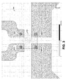
- FIG. 2 depicts a top-down view of antenna structures on a carrier, consistent with embodiments of the present disclosure.
- the first antenna structure operates as a dipole antenna with nulls in the Y direction, with the antenna radiation pattern providing adequate antenna gain in both the X direction and Z direction, which extends vertically from the image.
- the first antenna structure includes a pair of connection pads located within the dotted circle indicated by the interface arrow.
- An IC package with a (single) frontend communication circuit can be placed at this interface such that the first antenna structure is directly connected thereto (e.g. , driven by impedance-based modulation from the frontend circuit).
- a second antenna structure includes a conductive portion that is substantially perpendicular to the Y axis, upon which the nulls are located. This portion is located sufficiently close to the first antenna structure to allow electromagnetic coupling and to thereby produce a radiation pattern that complements the nulls. This combination of radiation patterns from the antenna structures results in a radiation pattern that is substantially more isotropic and directionally insensitive.
- the second antenna structure also includes a pair of connection pads located within the dotted circle indicated by the interface arrow. An IC package can be placed at this interface; however, the second antenna structure has no current path to a transmitter frontend circuit. This connection, however, can provide tamper protection/detection as discussed herein.
- the scale provided in FIG. 2 provides an example of the dimensions for the first and second antenna structures relative to an RFID circuit operating in the UHF frequency range of about 300MHz to 3GHz. More particular embodiments relate to an RFID circuit operating in the 860MHz to 960MHz frequency range. The embodiments discussed herein, however, are not necessarily limited to this specific size and can be adjusted according to the particular application. The specific shape of the first antenna structure can also be modified consistent with different dipole antenna designs.
- FIG. 3 depicts an interface portion for connecting between a carrier and an IC package, consistent with embodiments of the present disclosure.
- IC package 302 can be placed on the carrier 304, which includes four connection points.
- Two connection points, RFN and RFP, are part of the first antenna structure and can be directly driven by the IC package 302 at RF frequencies.
- the other two connection points, TP1 and TP2 are part of the second antenna structure and do not need to be directly driven at RF frequencies.
- the scale provided in FIG. 3 provides an example of the dimensions for the first and second antenna structures relative to an RFID circuit operating in the UHF frequency range. The embodiments discussed herein, however, are not necessarily limited to this specific size and can be adjusted according to the particular application.
- FIG. 4 depicts a radiation pattern (at 915 MHz) with nulls, consistent with embodiments of the present disclosure.
- the radiation pattern of FIG. 4 has a donut shape with its "hole” being located along the Y axis.
- This radiation pattern corresponds to a radiation pattern produced by a dipole antenna, such as the first antenna structure shown in FIG. 2 .
- the radiation pattern has an adequately strong gain (and corresponding tag sensitivity) in both the X and Z directions; however, the radiation along the Y axis is an effective null. This results in the corresponding device being directionally sensitive and thereby may force a user to properly orient the device before it can be used to communicate.
- FIG. 5 depicts a radiation pattern (at 915 MHz) in which the nulls have been complemented, consistent with embodiments of the present disclosure.
- the radiation pattern of FIG. 5 has significantly improved antenna gain (and corresponding tag sensitivity) along the Y axis, relative to the donut shape of FIG. 4 .
- This improvement corresponds to a complementing radiation pattern generated by a second antenna structure as discussed herein.
- the antenna gain along the Y axis may not be identical to the antenna gain along the X axis (and thus perfectly isotropic), it is substantially improved relative to the nulls existing in FIG. 4 .
- FIG. 6 depicts experimental label sensitivity plotted against frequency for devices oriented along the direction of nulls relative to a dipole antenna structure, consistent with embodiments of the present disclosure.
- Label sensitivity plot 604 represents a dipole antenna structure without a second antenna structure providing complementary antenna gain.
- Label sensitivity plot 602 represents a dipole antenna structure having a second antenna structure that provides complementary antenna gain, consistent with embodiments of the present disclosure.
- C summation output
- the use of formula, algorithm, or mathematical expression as descriptions is to be understood as having a physical embodiment in at least hardware (such as a processor circuit in which the techniques of the present disclosure may be practiced as well as implemented as an embodiment).
- machine-executable instructions are stored for execution in a manner consistent with one or more of the methods of the present disclosure.
- the instructions can be used to cause a general-purpose or special-purpose processor that is programmed with the instructions to perform the steps of various methods.
- the steps may be performed by specific hardware components that contain hardwired logic for performing the steps, or by any combination of programmed computer components and custom hardware components.
- aspects of the present disclosure may be provided as a computer program product, which may include a machine or computer-readable medium having stored thereon instructions, which may be used to program a computer (or other electronic devices) to perform a process according to the present disclosure.
- the computer-readable medium includes any type of media/machine-readable medium suitable for storing electronic instructions.
- modules may be implemented to carry out one or more of the operations and activities described herein and/or shown in the figures.
- a “module” is a circuit that carries out one or more of these or related operations/activities.
- one or more modules are discrete logic circuits or programmable logic circuits configured and arranged for implementing these operations/activities, as in the circuit modules shown in FIG. 1 .
- the programmable circuit is one (or more) computer circuits programmed to execute a set (or sets) of instructions (and/or configuration data).
- the instructions (and/or configuration data) can be in the form of firmware or software stored in and accessible from a memory (circuit).
- first and second modules include a combination of a CPU hardware-based circuit and a set of instructions in the form of firmware, where the first module includes a first CPU hardware circuit with one set of instructions and the second module includes a second CPU hardware circuit with another set of instructions.
Abstract
Description
- Aspects of the present disclosure relate to apparatuses, devices, and methods involving radio frequency (RF) communications and more particularly to antenna structures for use with RF communications.
- Ultrahigh frequency (UHF), around 300MHz to 3GHz, radio frequency (RF) identification (RFID) devices have a variety of different applications. In certain instances, an item is tagged with a tiny integrated circuit (IC) chip. The chip can be connected to an antenna, which might be fabricated on a substrate, such as a thin polyethylene terephthalate (PET) substrate. The combination chip and antenna (together called a "tag") allows a reader device to access data stored on the chip. For instance, a unique identifier (ID) can be accessed to facilitate the individual tagging/identification of items by a reader device. For example, each particular saleable good in a store can have its relevant parameters (model number, color, size, etc.) read electronically from a tag. Vehicles with RFID tags can be identified and charged for use of highway tollbooths, saving time and reducing traffic congestion. Devices or animals can be implanted with chips for tracking so that if lost, they can be easily returned to their owners. Depending upon the particular application, a reader device can scan the tag to access the data that it stores. This information can be processed by the reader device, stored in a database or otherwise communicated and processed.
- Many RFID devices provide a small, robust and cheap solution for RF communications of relatively small amounts of data. This facilitates their use on a large scale, in rugged conditions and in unobtrusive/space-limited locations. Notwithstanding, there can be competing desires for maintaining or improving these aspects while providing additional functionality and/or flexibility. This can be particularly true with regard to transmission circuits and associated antenna solutions.
- Consistent therewith, various embodiments of the present disclosure are directed toward antenna devices, communication/transmission circuits and associated methods, which can be applicable for RFID solutions.
- Aspects of the present disclosure are directed to systems and methods useful for RFID communications in multiple directions. These and other aspects of the present disclosure are exemplified in a number of illustrated implementations and applications, some of which are shown in the figures and characterized in the claims section that follows.
- A device is provided for use with a radio frequency identification (RFID) chip that receives and modulates a radio frequency (RF) signal. A substrate (e.g., a thin PET substrate) of the device includes a first short dipole antenna structure that backscatters a received RF signal to produce a first radiation pattern having nulls. A set of connection pads couples the RF signal from the antenna to a frontend transmitter circuit of the RFID chip. A second antenna structure backscatters the received RF signal by electromagnetic coupling to the first antenna structure and produces a second radiation pattern that complements the nulls in the first radiation pattern.
- Certain embodiments relate to a method for providing directionally insensitivity radiation in patterns. The method is carried out by receiving and modulating a radio frequency (RF) signal using a RFID frontend circuit. The modulated RF signal is backscattered using a first short dipole antenna structure that is configured to produce a first radiation pattern having nulls. The modulated RF signal is also backscattered by electromagnetically coupling a second antenna structure to the first antenna structure to produce a second radiation pattern that complements the nulls in the first radiation pattern.
- The above discussion is not intended to describe each embodiment or every implementation of the present disclosure. The figures, detailed description, and claims that follow more particularly exemplify various embodiments.
- Aspects of the present disclosure may be more completely understood in consideration of the detailed description of various embodiments of the present disclosure that follows in connection with the accompanying drawings, in which:
-
FIG. 1 depicts a block diagram of a system for RFID transmissions, consistent with embodiments of the present disclosure; -
FIG. 2 depicts a top-down view of antenna structures on a carrier, consistent with embodiments of the present disclosure; -
FIG. 3 depicts an interface portion for connecting between a substrate structure and an IC package, consistent with embodiments of the present disclosure; -
FIG. 4 depicts a radiation pattern with nulls, consistent with embodiments of the present disclosure; -
FIG. 5 depicts a radiation pattern in which the nulls have been complemented, consistent with embodiments of the present disclosure; and -
FIG. 6 depicts experimental tag sensitivities plotted against frequency for devices oriented along the direction of nulls relative to a dipole antenna structure, consistent with embodiments of the present disclosure. - While the disclosure is amenable to various modifications and alternative forms, specifics thereof have been shown by way of example in the drawings and will be described in detail. It should be understood, however, that the intention is not to limit the disclosure to the particular embodiments described. On the contrary, the intention is to cover all modifications, equivalents, and alternatives falling within the scope of the disclosure including aspects defined in the claims.
- Aspects of the present disclosure are believed to be applicable to a variety of different types of devices, systems and arrangements, including those that may be implemented in connection with an RFID solution and associated antenna structure(s). While the present disclosure is not necessarily limited to such applications, various aspects of the invention may be appreciated through a discussion of various examples using this context.
- Embodiments of the present disclosure are directed toward wireless communication solutions that use an antenna structure that functions as an electrically short dipole antenna. As used herein, an electrically short dipole antenna can have a length shorter than half a wavelength (including lengths that are less a tenth of a wavelength) and includes two rods connected to a transmission line at the center. A more complex dipole antenna is a folded dipole antenna, in which the two ends of the transmission lines are connected to complete a conductor loop. Other types of dipole antennas include unequal conductor folded dipoles, and multi-wire folded dipoles. Dipole antennas can be relatively easy to construct, model and design. They can also be readily implemented in substantially one or two dimensions (e.g., on a single layer of a printed circuit board (PCB)) and within a relatively small space. Aspects of the present disclosure relate to the recognition that, while a dipole antenna structure can provide certain benefits, a dipole antenna structure can be limited by the directional properties of its antenna gain. Accordingly, embodiments of the present disclosure are directed toward complementing dipole radiation patterns (produced by a dipole antenna) using a second antenna structure. The radiation patterns discussed herein can be relevant to both receipt and transmission of data. For instance, receipt of an RF signal from a reader device can be directionally limited by the radiation pattern in a manner similar to that of transmission, e.g., a transmission that uses backscattering of the RF signal after being modulated to convey data. Accordingly, the radiation patterns discussed herein are not limited to just transmission (or receipt) of data, unless otherwise specified.
- Embodiments are directed toward a device for use with a RFID chip that receives, modulates and then uses antenna structures to backscatter a RF signal. The device has a substrate that contains a first antenna structure configured and arranged to produce a first radiation pattern having nulls. A particular type of substrate is a (thin) PET substrate. Although not necessarily limited thereto, various embodiments are discussed as using such a (thin) PET substrate. As discussed herein, a null represent portions of the radiation pattern having antenna gain without consequence or significance relative to the overall radiation pattern. Thus, a null can have a minor, inconsequential, amount of radiated signal strength. The PET substrate can include a set of connection pads configured and arranged to receive the RF signal and provide the RF signal to the antenna structure. A second antenna structure is configured and arranged to receive the RF signal using electromagnetic coupling with the first antenna structure and to produce a second radiation pattern that complements the nulls in the first radiation pattern. The resulting radiation pattern thereby provides increased antenna gain for the direction corresponding to the nulls. Through the use of electromagnetic coupling, the RFID chip can be configured as a single frontend transmission device that is directly connected (via a current path) to the first antenna structure, but not a second antenna structure. In this manner, the second antenna structure does not need to be linked using a conductor that provides current from a (second) transmitter circuit.
- Certain embodiments are directed toward the second antenna structure being configured for multiple purposes. In particular, the device can be designed to use the second antenna structure for tamper protection. In certain applications, the second antenna structure can be configured to function in connection with a safety seal. For instance, a protection label can be placed over components to hide them from tampering attempts. The second antenna structure can be configured as a continuous conductor between two connection pads. An IC package can then be connected to both of the connection pads. The label can be placed over the second antenna structure so that the continuous conductor is broken if the label is peeled off or manipulated. Logic circuitry (e.g., in a chip of the IC) can detect the break and trigger a lock or alarm.
- Consistent with embodiments of the present disclosure, the IC package can be configured with a programmable output that is connected to the second antenna structure. For instance, the programmable output can be driven to a voltage level to detect whether or not the device has been tampered with. The output can be driven in response to an event (e.g., upon power up or upon detection of an external communication signal), periodically or always driven. This can be particularly useful for allowing the second antenna structure to be passively driven by the electromagnetic coupling to the first antenna structure. For example, driving the second antenna structure to a supply voltage can introduce undesired noise caused by fluctuations in the supply voltage.
- Turning now to the figures,
FIG. 1 depicts a block diagram of a system for RFID transmissions, consistent with embodiments of the present disclosure.IC package 102 houses one or more IC chip(s). The chips include logic circuitry that is configured to provide the functionality of the logic modules/circuitry module 108 communicates via RF signals received from a connected antenna. During receipt of data, thefrontend circuitry 108 can be configured to decode data modulated in an RF carrier. During transmission of data, thefrontend circuitry 108 can be configured to encode data by modulating the received (from reader devices) RF carrier signal such that the backscattered RF signal can be decoded by a reader device. For instance, the RF carrier signal can be modulated by varying internal impedance of thefrontend circuitry 108. In particular embodiments, theIC package 102 is configured to provide asingle frontend circuitry 108. Thus, only one antenna structure is directly driven, with an RF signal, by circuitry in theIC package 102. - Various embodiments are directed toward a tamper protection interface module/
circuitry 110 that provides a tamper protection interface. This tamperprotection interface module 110 can detect attempts to gain physical access to components of the system. For instance, the interface can detect the effective resistance between two output connection points to detect a break in a conductor. - Processing circuitry/
module 106 provides various functionality including, but not limited to, data handling and security for baseband access to data stored in a local memory. This processing can include disabling memory access in response to detecting tampering, encryption/decryption algorithms and decoding and encoding data communicated over theRFID interface 108. Data communicated with theRFID interface 108, whether transmitted to or received from, can be converted between baseband and RF frequencies. Moreover, the RFID interface can modulate and/or demodulate the communicated data according to the particular transmission protocol(s). - Carrier/
substrate 104 is configured to interface withIC package 102 and to provide two antenna structures. For instance, a first antenna structure is connected to theIC package 102 at connection points 112 and 114 and a second antenna structure is connected to theIC package 102 at connection points 116 and 118.Substrate 104 can include one or more layers, each layer providing one or more of routing space for interconnections and/or power-planes. For instance, a design could include a two layer substrate. The two layers could be metal (e.g., copper) layers on the front and the back of the substrate. From these layers component footprints, vias, and traces can be formed by etching away the metal. In certain embodiments, the antenna structures can be constructed from conductors located on the same layer of thesubstrate 104. -
Substrate 104 can include a footprint that corresponds to the output connections for theIC package 102. For instance, the footprint can correspond to a surface mount layout (e.g., thin small-outline packages (TSOPs), Small Outline Transistor packages (SOTs), flip chip strap packages (FCSs), etc.). In certain instances, solder connections/balls 120 connect thecarrier 104 to theIC package 102. - Consistent with embodiments of the present disclosure, a device includes the
substrate 104 as a printed circuit board in which the first antenna structure is configured and arranged to produce a first radiation pattern. This radiation pattern has nulls. For instance, the first antenna structure can be configured as a dipole antenna having nulls along a common axis of the dipole antenna. Connection pads on thesubstrate 104 are configured and arranged to transmit RF signals between theIC package 102 to the first antenna structure by providing a current path. This can result in a directionally-limited radiation pattern, which would otherwise force a user of the device to properly orient the device relative to a reader device. Accordingly, a second antenna structure is configured and arranged to receive the RF signal. The second antenna structure is also electromagnetically coupled to the first antenna structure and to produce a second radiation pattern that complements the nulls in the first radiation pattern. For instance, the second antenna structure can be configured to run perpendicular to the first antenna structure and in close enough proximity to provide near-field antenna coupling. The length and orientation of the second antenna structure provides a second radiation pattern that complements the first radiation pattern by providing antenna gain at the nulls of the first radiation pattern. In a particular instance, the nulls are located on a common axis and the second antenna structure is substantially perpendicular to this common axis. - More particular embodiments are directed toward the configuration and use of the second antenna structure to provide tamper detection. The tamper detection can be provided by way of a current path along the second antenna structure. The second antenna structure can be configured and arranged to break the current path in response to tampering with the device (e.g., removal of a label breaks a conductive portion of the second antenna structure).
- Particular aspects of the present disclosure recognize that such a device can provide near isotropic radiation patterns without the use of a second frequency RFID circuit configured and arranged to generate a second version of the RF signal. For instance, this radiation pattern can be provided without the use of two simultaneous and decoupled dipoles, each of which is connected to a different, dedicated RF frontend, thereby requiring a dual frontend IC. Other aspects of the present disclosure recognize that even where such dipoles are oriented perpendicular to each other, if such an antenna structure is connected to the single frontend (via galvanic or magnetic coupling), the radiation pattern merely rotates and does not substantially complement the nulls (e.g., preserving the shape, typically a donut shape for dipole antennas, of the first radiation pattern).
-
FIG. 2 depicts a top-down view of antenna structures on a carrier, consistent with embodiments of the present disclosure. The first antenna structure operates as a dipole antenna with nulls in the Y direction, with the antenna radiation pattern providing adequate antenna gain in both the X direction and Z direction, which extends vertically from the image. The first antenna structure includes a pair of connection pads located within the dotted circle indicated by the interface arrow. An IC package with a (single) frontend communication circuit can be placed at this interface such that the first antenna structure is directly connected thereto (e.g., driven by impedance-based modulation from the frontend circuit). - A second antenna structure includes a conductive portion that is substantially perpendicular to the Y axis, upon which the nulls are located. This portion is located sufficiently close to the first antenna structure to allow electromagnetic coupling and to thereby produce a radiation pattern that complements the nulls. This combination of radiation patterns from the antenna structures results in a radiation pattern that is substantially more isotropic and directionally insensitive. The second antenna structure also includes a pair of connection pads located within the dotted circle indicated by the interface arrow. An IC package can be placed at this interface; however, the second antenna structure has no current path to a transmitter frontend circuit. This connection, however, can provide tamper protection/detection as discussed herein.
- The scale provided in
FIG. 2 provides an example of the dimensions for the first and second antenna structures relative to an RFID circuit operating in the UHF frequency range of about 300MHz to 3GHz. More particular embodiments relate to an RFID circuit operating in the 860MHz to 960MHz frequency range. The embodiments discussed herein, however, are not necessarily limited to this specific size and can be adjusted according to the particular application. The specific shape of the first antenna structure can also be modified consistent with different dipole antenna designs. -
FIG. 3 depicts an interface portion for connecting between a carrier and an IC package, consistent with embodiments of the present disclosure.IC package 302 can be placed on thecarrier 304, which includes four connection points. Two connection points, RFN and RFP, are part of the first antenna structure and can be directly driven by theIC package 302 at RF frequencies. The other two connection points, TP1 and TP2, are part of the second antenna structure and do not need to be directly driven at RF frequencies. The scale provided inFIG. 3 provides an example of the dimensions for the first and second antenna structures relative to an RFID circuit operating in the UHF frequency range. The embodiments discussed herein, however, are not necessarily limited to this specific size and can be adjusted according to the particular application. -
FIG. 4 depicts a radiation pattern (at 915 MHz) with nulls, consistent with embodiments of the present disclosure. The radiation pattern ofFIG. 4 has a donut shape with its "hole" being located along the Y axis. This radiation pattern corresponds to a radiation pattern produced by a dipole antenna, such as the first antenna structure shown inFIG. 2 . The radiation pattern has an adequately strong gain (and corresponding tag sensitivity) in both the X and Z directions; however, the radiation along the Y axis is an effective null. This results in the corresponding device being directionally sensitive and thereby may force a user to properly orient the device before it can be used to communicate. -
FIG. 5 depicts a radiation pattern (at 915 MHz) in which the nulls have been complemented, consistent with embodiments of the present disclosure. The radiation pattern ofFIG. 5 has significantly improved antenna gain (and corresponding tag sensitivity) along the Y axis, relative to the donut shape ofFIG. 4 . This improvement corresponds to a complementing radiation pattern generated by a second antenna structure as discussed herein. Although the antenna gain along the Y axis may not be identical to the antenna gain along the X axis (and thus perfectly isotropic), it is substantially improved relative to the nulls existing inFIG. 4 . -
FIG. 6 depicts experimental label sensitivity plotted against frequency for devices oriented along the direction of nulls relative to a dipole antenna structure, consistent with embodiments of the present disclosure. The depicted parameter, dBmW, refers to the power ratio indecibels (dB) of the measured power referenced to one milliwatt (mW) (e.g., 30dBmW = 30dB over 1mW; or - 10dBmW = -10dB over 1mW) and is shown for each of the depicted frequencies between 840MHz and 960MHz. Accordingly, smaller values of dBmW represent good tag sensitivity (or alternatively, good antenna gain).Label sensitivity plot 604 represents a dipole antenna structure without a second antenna structure providing complementary antenna gain.Label sensitivity plot 602 represents a dipole antenna structure having a second antenna structure that provides complementary antenna gain, consistent with embodiments of the present disclosure. - The signals and associated logic and functionality described in connection with the figures can be implemented in a number of different manners. Unless otherwise indicated, various general-purpose systems and/or logic circuitry may be used with programs in accordance with the teachings herein, or it may prove convenient to use a more specialized apparatus to perform the disclosed aspects. For example, according to the present disclosure, one or more of the methods can be implemented in hard-wired circuitry by programming a general-purpose processor, a digital signal processor (DSP), other fully or semi-programmable logic circuitry, and/or by a combination of such hardware and a general-purpose processor configured with software. Accordingly, the various components and processes shown in the figures can be implemented in a variety of circuit-based forms, such as through the use of data processing circuit modules.
- It is recognized that aspects of the disclosure can be practiced with circuits and computer/processor-based system configurations other than those expressly described herein. The corresponding structure for a variety of these systems and circuits would be apparent from the intended application and the above description.
- The various terms and techniques are used by those knowledgeable in the art to describe aspects relating to one or more of communications, protocols, applications, implementations, and mechanisms. One such technique is the description of an implementation of a technique expressed in terms of an algorithm or mathematical expression. While such techniques may be implemented, for example, by executing code on a computer processor, the expression of that technique may be conveyed and communicated as a formula, algorithm, or mathematical expression.
- For example, a block or module denoting "C=A+B" as an additive function implemented in hardware and/or software would take two inputs (A and B) and produce a summation output (C), such as in combinatorial logic circuitry. Thus, the use of formula, algorithm, or mathematical expression as descriptions is to be understood as having a physical embodiment in at least hardware (such as a processor circuit in which the techniques of the present disclosure may be practiced as well as implemented as an embodiment).
- In certain embodiments, machine-executable instructions are stored for execution in a manner consistent with one or more of the methods of the present disclosure. The instructions can be used to cause a general-purpose or special-purpose processor that is programmed with the instructions to perform the steps of various methods. The steps may be performed by specific hardware components that contain hardwired logic for performing the steps, or by any combination of programmed computer components and custom hardware components.
- In some embodiments, aspects of the present disclosure may be provided as a computer program product, which may include a machine or computer-readable medium having stored thereon instructions, which may be used to program a computer (or other electronic devices) to perform a process according to the present disclosure. Accordingly, the computer-readable medium includes any type of media/machine-readable medium suitable for storing electronic instructions.
- Various modules may be implemented to carry out one or more of the operations and activities described herein and/or shown in the figures. In these contexts, a "module" is a circuit that carries out one or more of these or related operations/activities. For example, in certain of the above-discussed embodiments, one or more modules are discrete logic circuits or programmable logic circuits configured and arranged for implementing these operations/activities, as in the circuit modules shown in
FIG. 1 . In certain embodiments, the programmable circuit is one (or more) computer circuits programmed to execute a set (or sets) of instructions (and/or configuration data). The instructions (and/or configuration data) can be in the form of firmware or software stored in and accessible from a memory (circuit). As an example, first and second modules include a combination of a CPU hardware-based circuit and a set of instructions in the form of firmware, where the first module includes a first CPU hardware circuit with one set of instructions and the second module includes a second CPU hardware circuit with another set of instructions. - The various embodiments described above are provided by way of illustration only and should not be construed to limit the disclosure. Based on the above discussion and illustrations, those skilled in the art will readily recognize that various modifications and changes may be made to the present disclosure without strictly following the exemplary embodiments and applications illustrated and described herein. Such modifications and changes do not depart from the true spirit and scope of the present disclosure, which is set forth in the following claims.
Claims (10)
- A device for use with a radio frequency identification (RFID) chip that receives and modulates a radio frequency (RF) signal, the device comprising:- a substrate having:- a first short dipole antenna structure configured and arranged to backscatter a received RF signal to produce a first radiation pattern having nulls;- a set of connection pads configured and arranged to couple the RF signal from the antenna to a frontend transmitter circuit of the RFID chip; and- a second antenna structure configured and arranged to backscatter the received RF signal by electromagnetic coupling to the first antenna structure and to produce a second radiation pattern that complements the nulls in the first radiation pattern.
- The device of claim 1, wherein the first radiation pattern is a dipole radiation pattern and the nulls are located on a common axis.
- The device of claim 1, wherein the first radiation pattern is a dipole radiation pattern, the nulls are located on a common axis and the second antenna structure is substantially perpendicular to the common axis.
- The device of claim 1, wherein the second antenna structure is further configured and arranged to provide tamper detection by providing a current path along the second antenna structure, the current path configured and arranged to break in response to tampering with the device.
- The device of claim 1, further including a protection label and wherein the second antenna structure is further configured and arranged to provide tamper detection by breaking a portion of the second antenna structure in response to removing the protection label.
- The device of claim 1, wherein the device includes the radio frequency identification (RFID) chip and does not include a second frequency RFID circuit configured and arranged to modulate the RF signal.
- The device of claim 1, wherein the device further includes an integrated circuit (IC) package that contains the RFID chip, the IC package including:- a processing module configured and arranged to process data at baseband;
an RFID transmitter module configured and arranged to convert data between RF and baseband; and- a tamper protection module configured and arranged to detect physical tampering with the IC package by detecting a break in a current path provided by the second antenna structure. - The device of claim 1, wherein the device further includes an integrated circuit (IC) package that contains the RFID chip and wherein the frontend transmitter circuit is configured and arranged to receive and modulate the RF signal at ultrahigh frequencies (UHF).
- The device of claim 1, wherein the device further includes an integrated circuit (IC) package that contains the RFID chip and wherein the frontend transmitter circuit is configured and arranged to receive and modulate the RF signal at frequencies between 860 MHz and 960MHz.
- The device of claim 1, wherein the substrate is a thin polyethylene terephthalate substrate.
Applications Claiming Priority (1)
| Application Number | Priority Date | Filing Date | Title |
|---|---|---|---|
| US13/599,201 US9324020B2 (en) | 2012-08-30 | 2012-08-30 | Antenna structures and methods for omni directional radiation patterns |
Publications (2)
| Publication Number | Publication Date |
|---|---|
| EP2704250A1 true EP2704250A1 (en) | 2014-03-05 |
| EP2704250B1 EP2704250B1 (en) | 2016-11-30 |
Family
ID=49080683
Family Applications (1)
| Application Number | Title | Priority Date | Filing Date |
|---|---|---|---|
| EP13181742.1A Active EP2704250B1 (en) | 2012-08-30 | 2013-08-26 | Antenna structures and methods for omnidirectional radiation patterns |
Country Status (2)
| Country | Link |
|---|---|
| US (1) | US9324020B2 (en) |
| EP (1) | EP2704250B1 (en) |
Cited By (2)
| Publication number | Priority date | Publication date | Assignee | Title |
|---|---|---|---|---|
| GB2564398A (en) * | 2017-07-06 | 2019-01-16 | Quickwy Ltd | Radio-frequency identification for tracking and securing inventory |
| CN111509363A (en) * | 2019-01-31 | 2020-08-07 | 北京小米移动软件有限公司 | Terminal device |
Families Citing this family (150)
| Publication number | Priority date | Publication date | Assignee | Title |
|---|---|---|---|---|
| US10009065B2 (en) | 2012-12-05 | 2018-06-26 | At&T Intellectual Property I, L.P. | Backhaul link for distributed antenna system |
| US9113347B2 (en) | 2012-12-05 | 2015-08-18 | At&T Intellectual Property I, Lp | Backhaul link for distributed antenna system |
| US9999038B2 (en) | 2013-05-31 | 2018-06-12 | At&T Intellectual Property I, L.P. | Remote distributed antenna system |
| US9525524B2 (en) | 2013-05-31 | 2016-12-20 | At&T Intellectual Property I, L.P. | Remote distributed antenna system |
| FR3009410B1 (en) * | 2013-07-31 | 2015-08-28 | Oberthur Technologies | INTEGRATED COUPLING ELECTRONIC ENTITY BETWEEN A MICROCIRCUIT AND ANTENNA AND METHOD FOR MANUFACTURING THE SAME |
| US8897697B1 (en) | 2013-11-06 | 2014-11-25 | At&T Intellectual Property I, Lp | Millimeter-wave surface-wave communications |
| US9692101B2 (en) | 2014-08-26 | 2017-06-27 | At&T Intellectual Property I, L.P. | Guided wave couplers for coupling electromagnetic waves between a waveguide surface and a surface of a wire |
| US9960814B2 (en) * | 2014-09-01 | 2018-05-01 | E-Garde Co., Ltd. | Contactless information communication terminal unit, card-type device, portable telephone, and wearable device |
| US9768833B2 (en) | 2014-09-15 | 2017-09-19 | At&T Intellectual Property I, L.P. | Method and apparatus for sensing a condition in a transmission medium of electromagnetic waves |
| US10063280B2 (en) | 2014-09-17 | 2018-08-28 | At&T Intellectual Property I, L.P. | Monitoring and mitigating conditions in a communication network |
| US9615269B2 (en) | 2014-10-02 | 2017-04-04 | At&T Intellectual Property I, L.P. | Method and apparatus that provides fault tolerance in a communication network |
| US9685992B2 (en) | 2014-10-03 | 2017-06-20 | At&T Intellectual Property I, L.P. | Circuit panel network and methods thereof |
| US9503189B2 (en) | 2014-10-10 | 2016-11-22 | At&T Intellectual Property I, L.P. | Method and apparatus for arranging communication sessions in a communication system |
| US9973299B2 (en) | 2014-10-14 | 2018-05-15 | At&T Intellectual Property I, L.P. | Method and apparatus for adjusting a mode of communication in a communication network |
| US9762289B2 (en) | 2014-10-14 | 2017-09-12 | At&T Intellectual Property I, L.P. | Method and apparatus for transmitting or receiving signals in a transportation system |
| US9780834B2 (en) | 2014-10-21 | 2017-10-03 | At&T Intellectual Property I, L.P. | Method and apparatus for transmitting electromagnetic waves |
| US9312919B1 (en) | 2014-10-21 | 2016-04-12 | At&T Intellectual Property I, Lp | Transmission device with impairment compensation and methods for use therewith |
| US9653770B2 (en) | 2014-10-21 | 2017-05-16 | At&T Intellectual Property I, L.P. | Guided wave coupler, coupling module and methods for use therewith |
| US9627768B2 (en) | 2014-10-21 | 2017-04-18 | At&T Intellectual Property I, L.P. | Guided-wave transmission device with non-fundamental mode propagation and methods for use therewith |
| US9577306B2 (en) | 2014-10-21 | 2017-02-21 | At&T Intellectual Property I, L.P. | Guided-wave transmission device and methods for use therewith |
| US9520945B2 (en) | 2014-10-21 | 2016-12-13 | At&T Intellectual Property I, L.P. | Apparatus for providing communication services and methods thereof |
| US9769020B2 (en) | 2014-10-21 | 2017-09-19 | At&T Intellectual Property I, L.P. | Method and apparatus for responding to events affecting communications in a communication network |
| US9800327B2 (en) | 2014-11-20 | 2017-10-24 | At&T Intellectual Property I, L.P. | Apparatus for controlling operations of a communication device and methods thereof |
| US10009067B2 (en) | 2014-12-04 | 2018-06-26 | At&T Intellectual Property I, L.P. | Method and apparatus for configuring a communication interface |
| US9544006B2 (en) | 2014-11-20 | 2017-01-10 | At&T Intellectual Property I, L.P. | Transmission device with mode division multiplexing and methods for use therewith |
| US10243784B2 (en) | 2014-11-20 | 2019-03-26 | At&T Intellectual Property I, L.P. | System for generating topology information and methods thereof |
| US9742462B2 (en) | 2014-12-04 | 2017-08-22 | At&T Intellectual Property I, L.P. | Transmission medium and communication interfaces and methods for use therewith |
| US10340573B2 (en) | 2016-10-26 | 2019-07-02 | At&T Intellectual Property I, L.P. | Launcher with cylindrical coupling device and methods for use therewith |
| US9954287B2 (en) | 2014-11-20 | 2018-04-24 | At&T Intellectual Property I, L.P. | Apparatus for converting wireless signals and electromagnetic waves and methods thereof |
| US9461706B1 (en) | 2015-07-31 | 2016-10-04 | At&T Intellectual Property I, Lp | Method and apparatus for exchanging communication signals |
| US9997819B2 (en) | 2015-06-09 | 2018-06-12 | At&T Intellectual Property I, L.P. | Transmission medium and method for facilitating propagation of electromagnetic waves via a core |
| US10144036B2 (en) | 2015-01-30 | 2018-12-04 | At&T Intellectual Property I, L.P. | Method and apparatus for mitigating interference affecting a propagation of electromagnetic waves guided by a transmission medium |
| US9876570B2 (en) | 2015-02-20 | 2018-01-23 | At&T Intellectual Property I, Lp | Guided-wave transmission device with non-fundamental mode propagation and methods for use therewith |
| US9749013B2 (en) | 2015-03-17 | 2017-08-29 | At&T Intellectual Property I, L.P. | Method and apparatus for reducing attenuation of electromagnetic waves guided by a transmission medium |
| US10224981B2 (en) | 2015-04-24 | 2019-03-05 | At&T Intellectual Property I, Lp | Passive electrical coupling device and methods for use therewith |
| US9705561B2 (en) | 2015-04-24 | 2017-07-11 | At&T Intellectual Property I, L.P. | Directional coupling device and methods for use therewith |
| US9948354B2 (en) | 2015-04-28 | 2018-04-17 | At&T Intellectual Property I, L.P. | Magnetic coupling device with reflective plate and methods for use therewith |
| US9793954B2 (en) | 2015-04-28 | 2017-10-17 | At&T Intellectual Property I, L.P. | Magnetic coupling device and methods for use therewith |
| US9748626B2 (en) | 2015-05-14 | 2017-08-29 | At&T Intellectual Property I, L.P. | Plurality of cables having different cross-sectional shapes which are bundled together to form a transmission medium |
| US9490869B1 (en) | 2015-05-14 | 2016-11-08 | At&T Intellectual Property I, L.P. | Transmission medium having multiple cores and methods for use therewith |
| US9871282B2 (en) | 2015-05-14 | 2018-01-16 | At&T Intellectual Property I, L.P. | At least one transmission medium having a dielectric surface that is covered at least in part by a second dielectric |
| US10650940B2 (en) | 2015-05-15 | 2020-05-12 | At&T Intellectual Property I, L.P. | Transmission medium having a conductive material and methods for use therewith |
| US9917341B2 (en) | 2015-05-27 | 2018-03-13 | At&T Intellectual Property I, L.P. | Apparatus and method for launching electromagnetic waves and for modifying radial dimensions of the propagating electromagnetic waves |
| US9866309B2 (en) | 2015-06-03 | 2018-01-09 | At&T Intellectual Property I, Lp | Host node device and methods for use therewith |
| US10103801B2 (en) | 2015-06-03 | 2018-10-16 | At&T Intellectual Property I, L.P. | Host node device and methods for use therewith |
| US10812174B2 (en) | 2015-06-03 | 2020-10-20 | At&T Intellectual Property I, L.P. | Client node device and methods for use therewith |
| US9912381B2 (en) | 2015-06-03 | 2018-03-06 | At&T Intellectual Property I, Lp | Network termination and methods for use therewith |
| US9913139B2 (en) | 2015-06-09 | 2018-03-06 | At&T Intellectual Property I, L.P. | Signal fingerprinting for authentication of communicating devices |
| US10142086B2 (en) | 2015-06-11 | 2018-11-27 | At&T Intellectual Property I, L.P. | Repeater and methods for use therewith |
| US9608692B2 (en) | 2015-06-11 | 2017-03-28 | At&T Intellectual Property I, L.P. | Repeater and methods for use therewith |
| US9820146B2 (en) | 2015-06-12 | 2017-11-14 | At&T Intellectual Property I, L.P. | Method and apparatus for authentication and identity management of communicating devices |
| US9667317B2 (en) | 2015-06-15 | 2017-05-30 | At&T Intellectual Property I, L.P. | Method and apparatus for providing security using network traffic adjustments |
| US9865911B2 (en) | 2015-06-25 | 2018-01-09 | At&T Intellectual Property I, L.P. | Waveguide system for slot radiating first electromagnetic waves that are combined into a non-fundamental wave mode second electromagnetic wave on a transmission medium |
| US9509415B1 (en) | 2015-06-25 | 2016-11-29 | At&T Intellectual Property I, L.P. | Methods and apparatus for inducing a fundamental wave mode on a transmission medium |
| US9640850B2 (en) | 2015-06-25 | 2017-05-02 | At&T Intellectual Property I, L.P. | Methods and apparatus for inducing a non-fundamental wave mode on a transmission medium |
| US9882257B2 (en) | 2015-07-14 | 2018-01-30 | At&T Intellectual Property I, L.P. | Method and apparatus for launching a wave mode that mitigates interference |
| US9853342B2 (en) | 2015-07-14 | 2017-12-26 | At&T Intellectual Property I, L.P. | Dielectric transmission medium connector and methods for use therewith |
| US10341142B2 (en) | 2015-07-14 | 2019-07-02 | At&T Intellectual Property I, L.P. | Apparatus and methods for generating non-interfering electromagnetic waves on an uninsulated conductor |
| US10148016B2 (en) | 2015-07-14 | 2018-12-04 | At&T Intellectual Property I, L.P. | Apparatus and methods for communicating utilizing an antenna array |
| US9628116B2 (en) | 2015-07-14 | 2017-04-18 | At&T Intellectual Property I, L.P. | Apparatus and methods for transmitting wireless signals |
| US9722318B2 (en) | 2015-07-14 | 2017-08-01 | At&T Intellectual Property I, L.P. | Method and apparatus for coupling an antenna to a device |
| US10320586B2 (en) | 2015-07-14 | 2019-06-11 | At&T Intellectual Property I, L.P. | Apparatus and methods for generating non-interfering electromagnetic waves on an insulated transmission medium |
| US10033108B2 (en) | 2015-07-14 | 2018-07-24 | At&T Intellectual Property I, L.P. | Apparatus and methods for generating an electromagnetic wave having a wave mode that mitigates interference |
| US10033107B2 (en) | 2015-07-14 | 2018-07-24 | At&T Intellectual Property I, L.P. | Method and apparatus for coupling an antenna to a device |
| US10205655B2 (en) | 2015-07-14 | 2019-02-12 | At&T Intellectual Property I, L.P. | Apparatus and methods for communicating utilizing an antenna array and multiple communication paths |
| US10044409B2 (en) | 2015-07-14 | 2018-08-07 | At&T Intellectual Property I, L.P. | Transmission medium and methods for use therewith |
| US10170840B2 (en) | 2015-07-14 | 2019-01-01 | At&T Intellectual Property I, L.P. | Apparatus and methods for sending or receiving electromagnetic signals |
| US9847566B2 (en) | 2015-07-14 | 2017-12-19 | At&T Intellectual Property I, L.P. | Method and apparatus for adjusting a field of a signal to mitigate interference |
| US9608740B2 (en) | 2015-07-15 | 2017-03-28 | At&T Intellectual Property I, L.P. | Method and apparatus for launching a wave mode that mitigates interference |
| US10090606B2 (en) | 2015-07-15 | 2018-10-02 | At&T Intellectual Property I, L.P. | Antenna system with dielectric array and methods for use therewith |
| US9793951B2 (en) | 2015-07-15 | 2017-10-17 | At&T Intellectual Property I, L.P. | Method and apparatus for launching a wave mode that mitigates interference |
| US9871283B2 (en) | 2015-07-23 | 2018-01-16 | At&T Intellectual Property I, Lp | Transmission medium having a dielectric core comprised of plural members connected by a ball and socket configuration |
| US9948333B2 (en) | 2015-07-23 | 2018-04-17 | At&T Intellectual Property I, L.P. | Method and apparatus for wireless communications to mitigate interference |
| US9749053B2 (en) | 2015-07-23 | 2017-08-29 | At&T Intellectual Property I, L.P. | Node device, repeater and methods for use therewith |
| US9912027B2 (en) | 2015-07-23 | 2018-03-06 | At&T Intellectual Property I, L.P. | Method and apparatus for exchanging communication signals |
| US9967173B2 (en) | 2015-07-31 | 2018-05-08 | At&T Intellectual Property I, L.P. | Method and apparatus for authentication and identity management of communicating devices |
| US9735833B2 (en) | 2015-07-31 | 2017-08-15 | At&T Intellectual Property I, L.P. | Method and apparatus for communications management in a neighborhood network |
| US9904535B2 (en) | 2015-09-14 | 2018-02-27 | At&T Intellectual Property I, L.P. | Method and apparatus for distributing software |
| US10186126B2 (en) * | 2015-09-15 | 2019-01-22 | Avery Dennison Retail Information Services, Llc | Multi-port straps incorporating sensing features |
| US10079661B2 (en) | 2015-09-16 | 2018-09-18 | At&T Intellectual Property I, L.P. | Method and apparatus for use with a radio distributed antenna system having a clock reference |
| US10009063B2 (en) | 2015-09-16 | 2018-06-26 | At&T Intellectual Property I, L.P. | Method and apparatus for use with a radio distributed antenna system having an out-of-band reference signal |
| US10136434B2 (en) | 2015-09-16 | 2018-11-20 | At&T Intellectual Property I, L.P. | Method and apparatus for use with a radio distributed antenna system having an ultra-wideband control channel |
| US9769128B2 (en) | 2015-09-28 | 2017-09-19 | At&T Intellectual Property I, L.P. | Method and apparatus for encryption of communications over a network |
| US9729197B2 (en) | 2015-10-01 | 2017-08-08 | At&T Intellectual Property I, L.P. | Method and apparatus for communicating network management traffic over a network |
| US9876264B2 (en) | 2015-10-02 | 2018-01-23 | At&T Intellectual Property I, Lp | Communication system, guided wave switch and methods for use therewith |
| US10355367B2 (en) | 2015-10-16 | 2019-07-16 | At&T Intellectual Property I, L.P. | Antenna structure for exchanging wireless signals |
| US10665942B2 (en) | 2015-10-16 | 2020-05-26 | At&T Intellectual Property I, L.P. | Method and apparatus for adjusting wireless communications |
| CN108352614B (en) | 2015-11-11 | 2020-10-23 | 沃克斯国际有限公司 | Omnidirectional television antenna with WIFI receiving capability |
| US9912419B1 (en) | 2016-08-24 | 2018-03-06 | At&T Intellectual Property I, L.P. | Method and apparatus for managing a fault in a distributed antenna system |
| US9860075B1 (en) | 2016-08-26 | 2018-01-02 | At&T Intellectual Property I, L.P. | Method and communication node for broadband distribution |
| DE102016010916A1 (en) * | 2016-09-08 | 2018-03-08 | Giesecke+Devrient Mobile Security Gmbh | security seal |
| US10291311B2 (en) | 2016-09-09 | 2019-05-14 | At&T Intellectual Property I, L.P. | Method and apparatus for mitigating a fault in a distributed antenna system |
| US11032819B2 (en) | 2016-09-15 | 2021-06-08 | At&T Intellectual Property I, L.P. | Method and apparatus for use with a radio distributed antenna system having a control channel reference signal |
| US10135147B2 (en) | 2016-10-18 | 2018-11-20 | At&T Intellectual Property I, L.P. | Apparatus and methods for launching guided waves via an antenna |
| US10135146B2 (en) | 2016-10-18 | 2018-11-20 | At&T Intellectual Property I, L.P. | Apparatus and methods for launching guided waves via circuits |
| US10340600B2 (en) | 2016-10-18 | 2019-07-02 | At&T Intellectual Property I, L.P. | Apparatus and methods for launching guided waves via plural waveguide systems |
| US9991580B2 (en) | 2016-10-21 | 2018-06-05 | At&T Intellectual Property I, L.P. | Launcher and coupling system for guided wave mode cancellation |
| US10374316B2 (en) | 2016-10-21 | 2019-08-06 | At&T Intellectual Property I, L.P. | System and dielectric antenna with non-uniform dielectric |
| US10811767B2 (en) | 2016-10-21 | 2020-10-20 | At&T Intellectual Property I, L.P. | System and dielectric antenna with convex dielectric radome |
| US9876605B1 (en) | 2016-10-21 | 2018-01-23 | At&T Intellectual Property I, L.P. | Launcher and coupling system to support desired guided wave mode |
| US10312567B2 (en) | 2016-10-26 | 2019-06-04 | At&T Intellectual Property I, L.P. | Launcher with planar strip antenna and methods for use therewith |
| US10498044B2 (en) | 2016-11-03 | 2019-12-03 | At&T Intellectual Property I, L.P. | Apparatus for configuring a surface of an antenna |
| US10225025B2 (en) | 2016-11-03 | 2019-03-05 | At&T Intellectual Property I, L.P. | Method and apparatus for detecting a fault in a communication system |
| US10224634B2 (en) | 2016-11-03 | 2019-03-05 | At&T Intellectual Property I, L.P. | Methods and apparatus for adjusting an operational characteristic of an antenna |
| US10291334B2 (en) | 2016-11-03 | 2019-05-14 | At&T Intellectual Property I, L.P. | System for detecting a fault in a communication system |
| US10340603B2 (en) | 2016-11-23 | 2019-07-02 | At&T Intellectual Property I, L.P. | Antenna system having shielded structural configurations for assembly |
| US10090594B2 (en) | 2016-11-23 | 2018-10-02 | At&T Intellectual Property I, L.P. | Antenna system having structural configurations for assembly |
| US10340601B2 (en) | 2016-11-23 | 2019-07-02 | At&T Intellectual Property I, L.P. | Multi-antenna system and methods for use therewith |
| US10535928B2 (en) | 2016-11-23 | 2020-01-14 | At&T Intellectual Property I, L.P. | Antenna system and methods for use therewith |
| US10178445B2 (en) | 2016-11-23 | 2019-01-08 | At&T Intellectual Property I, L.P. | Methods, devices, and systems for load balancing between a plurality of waveguides |
| US10305190B2 (en) | 2016-12-01 | 2019-05-28 | At&T Intellectual Property I, L.P. | Reflecting dielectric antenna system and methods for use therewith |
| US10361489B2 (en) | 2016-12-01 | 2019-07-23 | At&T Intellectual Property I, L.P. | Dielectric dish antenna system and methods for use therewith |
| US10135145B2 (en) | 2016-12-06 | 2018-11-20 | At&T Intellectual Property I, L.P. | Apparatus and methods for generating an electromagnetic wave along a transmission medium |
| US10727599B2 (en) | 2016-12-06 | 2020-07-28 | At&T Intellectual Property I, L.P. | Launcher with slot antenna and methods for use therewith |
| US10382976B2 (en) | 2016-12-06 | 2019-08-13 | At&T Intellectual Property I, L.P. | Method and apparatus for managing wireless communications based on communication paths and network device positions |
| US10439675B2 (en) | 2016-12-06 | 2019-10-08 | At&T Intellectual Property I, L.P. | Method and apparatus for repeating guided wave communication signals |
| US9927517B1 (en) | 2016-12-06 | 2018-03-27 | At&T Intellectual Property I, L.P. | Apparatus and methods for sensing rainfall |
| US10819035B2 (en) | 2016-12-06 | 2020-10-27 | At&T Intellectual Property I, L.P. | Launcher with helical antenna and methods for use therewith |
| US10020844B2 (en) | 2016-12-06 | 2018-07-10 | T&T Intellectual Property I, L.P. | Method and apparatus for broadcast communication via guided waves |
| US10326494B2 (en) | 2016-12-06 | 2019-06-18 | At&T Intellectual Property I, L.P. | Apparatus for measurement de-embedding and methods for use therewith |
| US10755542B2 (en) | 2016-12-06 | 2020-08-25 | At&T Intellectual Property I, L.P. | Method and apparatus for surveillance via guided wave communication |
| US10694379B2 (en) | 2016-12-06 | 2020-06-23 | At&T Intellectual Property I, L.P. | Waveguide system with device-based authentication and methods for use therewith |
| US10637149B2 (en) | 2016-12-06 | 2020-04-28 | At&T Intellectual Property I, L.P. | Injection molded dielectric antenna and methods for use therewith |
| US10168695B2 (en) | 2016-12-07 | 2019-01-01 | At&T Intellectual Property I, L.P. | Method and apparatus for controlling an unmanned aircraft |
| US10243270B2 (en) | 2016-12-07 | 2019-03-26 | At&T Intellectual Property I, L.P. | Beam adaptive multi-feed dielectric antenna system and methods for use therewith |
| US10027397B2 (en) | 2016-12-07 | 2018-07-17 | At&T Intellectual Property I, L.P. | Distributed antenna system and methods for use therewith |
| US10547348B2 (en) | 2016-12-07 | 2020-01-28 | At&T Intellectual Property I, L.P. | Method and apparatus for switching transmission mediums in a communication system |
| US10359749B2 (en) | 2016-12-07 | 2019-07-23 | At&T Intellectual Property I, L.P. | Method and apparatus for utilities management via guided wave communication |
| US10389029B2 (en) | 2016-12-07 | 2019-08-20 | At&T Intellectual Property I, L.P. | Multi-feed dielectric antenna system with core selection and methods for use therewith |
| US10446936B2 (en) | 2016-12-07 | 2019-10-15 | At&T Intellectual Property I, L.P. | Multi-feed dielectric antenna system and methods for use therewith |
| US9893795B1 (en) | 2016-12-07 | 2018-02-13 | At&T Intellectual Property I, Lp | Method and repeater for broadband distribution |
| US10139820B2 (en) | 2016-12-07 | 2018-11-27 | At&T Intellectual Property I, L.P. | Method and apparatus for deploying equipment of a communication system |
| US10389037B2 (en) | 2016-12-08 | 2019-08-20 | At&T Intellectual Property I, L.P. | Apparatus and methods for selecting sections of an antenna array and use therewith |
| US10601494B2 (en) | 2016-12-08 | 2020-03-24 | At&T Intellectual Property I, L.P. | Dual-band communication device and method for use therewith |
| US10938108B2 (en) | 2016-12-08 | 2021-03-02 | At&T Intellectual Property I, L.P. | Frequency selective multi-feed dielectric antenna system and methods for use therewith |
| US10103422B2 (en) | 2016-12-08 | 2018-10-16 | At&T Intellectual Property I, L.P. | Method and apparatus for mounting network devices |
| US10777873B2 (en) | 2016-12-08 | 2020-09-15 | At&T Intellectual Property I, L.P. | Method and apparatus for mounting network devices |
| US10530505B2 (en) | 2016-12-08 | 2020-01-07 | At&T Intellectual Property I, L.P. | Apparatus and methods for launching electromagnetic waves along a transmission medium |
| US10916969B2 (en) | 2016-12-08 | 2021-02-09 | At&T Intellectual Property I, L.P. | Method and apparatus for providing power using an inductive coupling |
| US10326689B2 (en) | 2016-12-08 | 2019-06-18 | At&T Intellectual Property I, L.P. | Method and system for providing alternative communication paths |
| US9911020B1 (en) | 2016-12-08 | 2018-03-06 | At&T Intellectual Property I, L.P. | Method and apparatus for tracking via a radio frequency identification device |
| US9998870B1 (en) | 2016-12-08 | 2018-06-12 | At&T Intellectual Property I, L.P. | Method and apparatus for proximity sensing |
| US10411356B2 (en) | 2016-12-08 | 2019-09-10 | At&T Intellectual Property I, L.P. | Apparatus and methods for selectively targeting communication devices with an antenna array |
| US10069535B2 (en) | 2016-12-08 | 2018-09-04 | At&T Intellectual Property I, L.P. | Apparatus and methods for launching electromagnetic waves having a certain electric field structure |
| US10264586B2 (en) | 2016-12-09 | 2019-04-16 | At&T Mobility Ii Llc | Cloud-based packet controller and methods for use therewith |
| US9838896B1 (en) | 2016-12-09 | 2017-12-05 | At&T Intellectual Property I, L.P. | Method and apparatus for assessing network coverage |
| US10340983B2 (en) | 2016-12-09 | 2019-07-02 | At&T Intellectual Property I, L.P. | Method and apparatus for surveying remote sites via guided wave communications |
| US9973940B1 (en) | 2017-02-27 | 2018-05-15 | At&T Intellectual Property I, L.P. | Apparatus and methods for dynamic impedance matching of a guided wave launcher |
| US10298293B2 (en) | 2017-03-13 | 2019-05-21 | At&T Intellectual Property I, L.P. | Apparatus of communication utilizing wireless network devices |
| US10593635B2 (en) * | 2018-03-27 | 2020-03-17 | Nxp B.V. | Multi-die and antenna array device |
Citations (4)
| Publication number | Priority date | Publication date | Assignee | Title |
|---|---|---|---|---|
| WO2005024745A2 (en) * | 2003-09-08 | 2005-03-17 | Claessens Frances M | Bottle cap |
| EP2251933A1 (en) * | 2008-03-03 | 2010-11-17 | Murata Manufacturing Co. Ltd. | Composite antenna |
| US20120018505A1 (en) * | 2010-07-23 | 2012-01-26 | Sensormatic Electronics , Llc | Tag having dipole-loop antenna |
| US20120145794A1 (en) * | 2010-08-30 | 2012-06-14 | Stefan Mieslinger | Tamper-Proof RFID Label |
Family Cites Families (11)
| Publication number | Priority date | Publication date | Assignee | Title |
|---|---|---|---|---|
| US4710775A (en) * | 1985-09-30 | 1987-12-01 | The Boeing Company | Parasitically coupled, complementary slot-dipole antenna element |
| US5572226A (en) * | 1992-05-15 | 1996-11-05 | Micron Technology, Inc. | Spherical antenna pattern(s) from antenna(s) arranged in a two-dimensional plane for use in RFID tags and labels |
| CN1081836C (en) * | 1995-06-21 | 2002-03-27 | 摩托罗拉公司 | Method and antenna for providing omnidirectional pattern |
| US6278413B1 (en) * | 1999-03-29 | 2001-08-21 | Intermec Ip Corporation | Antenna structure for wireless communications device, such as RFID tag |
| US7049962B2 (en) * | 2000-07-28 | 2006-05-23 | Micoh Corporation | Materials and construction for a tamper indicating radio frequency identification label |
| US6720930B2 (en) * | 2001-01-16 | 2004-04-13 | Digital Angel Corporation | Omnidirectional RFID antenna |
| US7042413B2 (en) * | 2003-08-22 | 2006-05-09 | Checkpoint Systems, Inc. | Security tag with three dimensional antenna array made from flat stock |
| JP2005316742A (en) * | 2004-04-28 | 2005-11-10 | Fuji Xerox Co Ltd | Ic tag |
| ES2617675T3 (en) * | 2004-10-28 | 2017-06-19 | Assa Abloy Ab | Safety sealing device comprising an RFID tag |
| US7772974B2 (en) * | 2005-02-28 | 2010-08-10 | Cypak Ab | Tamper evident seal system and method |
| EP2019425A1 (en) * | 2007-07-27 | 2009-01-28 | Semiconductor Energy Laboratory Co., Ltd. | Semiconductor device and method for manufacturing the same |
-
2012
- 2012-08-30 US US13/599,201 patent/US9324020B2/en active Active
-
2013
- 2013-08-26 EP EP13181742.1A patent/EP2704250B1/en active Active
Patent Citations (4)
| Publication number | Priority date | Publication date | Assignee | Title |
|---|---|---|---|---|
| WO2005024745A2 (en) * | 2003-09-08 | 2005-03-17 | Claessens Frances M | Bottle cap |
| EP2251933A1 (en) * | 2008-03-03 | 2010-11-17 | Murata Manufacturing Co. Ltd. | Composite antenna |
| US20120018505A1 (en) * | 2010-07-23 | 2012-01-26 | Sensormatic Electronics , Llc | Tag having dipole-loop antenna |
| US20120145794A1 (en) * | 2010-08-30 | 2012-06-14 | Stefan Mieslinger | Tamper-Proof RFID Label |
Cited By (2)
| Publication number | Priority date | Publication date | Assignee | Title |
|---|---|---|---|---|
| GB2564398A (en) * | 2017-07-06 | 2019-01-16 | Quickwy Ltd | Radio-frequency identification for tracking and securing inventory |
| CN111509363A (en) * | 2019-01-31 | 2020-08-07 | 北京小米移动软件有限公司 | Terminal device |
Also Published As
| Publication number | Publication date |
|---|---|
| US9324020B2 (en) | 2016-04-26 |
| US20140062787A1 (en) | 2014-03-06 |
| EP2704250B1 (en) | 2016-11-30 |
Similar Documents
| Publication | Publication Date | Title |
|---|---|---|
| EP2704250B1 (en) | Antenna structures and methods for omnidirectional radiation patterns | |
| US11107034B1 (en) | Portal monitoring with steered-beam RFID systems | |
| US7969313B2 (en) | Remote communication devices, radio frequency identification devices, wireless communication systems, wireless communication methods, radio frequency identification device communication methods, and methods of forming a remote communication device | |
| US7516901B2 (en) | RFID tag | |
| US20080048867A1 (en) | Discontinuous-Loop RFID Reader Antenna And Methods | |
| US6992634B2 (en) | Antenna device commonly used for two frequencies | |
| US9607286B1 (en) | RFID tags with brand protection and loss prevention | |
| US20080204238A1 (en) | Method to RFID enable electronic devices | |
| US10430623B1 (en) | RFID tag tracking using tag population management | |
| US7936268B2 (en) | Selectively coupling to feed points of an antenna system | |
| WO2021086906A1 (en) | Rfid ics with privacy modes | |
| US20090121965A1 (en) | Spherical antenna | |
| Mickle et al. | Physics and Geometry of RFID | |
| Kholodnyak et al. | 3D antenna for UHF RFID tags with eliminated read-orientation sensitivity | |
| US8937532B2 (en) | Reading RFID tag using antenna within enclosure | |
| US8350674B2 (en) | RFID tag including a loop antenna and RFID system using the RFID tag | |
| JP4920730B2 (en) | RF tag communication antenna device and RF tag reader / writer | |
| CN105069500A (en) | High security RFID label antenna, RFID label, and radio frequency method | |
| Jankowski-Mihułowicz et al. | Using the phased array antenna to increase geometric size of the interrogation zone in a UHF RFID system | |
| US8416062B2 (en) | Method and apparatus for improving RFID tag reading | |
| JP2004086683A (en) | Rf tag | |
| KR101206088B1 (en) | Rfid tag | |
| Qing et al. | UHF near-field RFID reader antenna | |
| KR101194070B1 (en) | Planar Folded Transmission Line Loop Antenna | |
| US11139589B2 (en) | Polarization uniqueness manipulation apparatus (PUMA) |
Legal Events
| Date | Code | Title | Description |
|---|---|---|---|
| AK | Designated contracting states |
Kind code of ref document: A1 Designated state(s): AL AT BE BG CH CY CZ DE DK EE ES FI FR GB GR HR HU IE IS IT LI LT LU LV MC MK MT NL NO PL PT RO RS SE SI SK SM TR |
|
| AX | Request for extension of the european patent |
Extension state: BA ME |
|
| PUAI | Public reference made under article 153(3) epc to a published international application that has entered the european phase |
Free format text: ORIGINAL CODE: 0009012 |
|
| 17P | Request for examination filed |
Effective date: 20140326 |
|
| RBV | Designated contracting states (corrected) |
Designated state(s): AL AT BE BG CH CY CZ DE DK EE ES FI FR GB GR HR HU IE IS IT LI LT LU LV MC MK MT NL NO PL PT RO RS SE SI SK SM TR |
|
| GRAP | Despatch of communication of intention to grant a patent |
Free format text: ORIGINAL CODE: EPIDOSNIGR1 |
|
| INTG | Intention to grant announced |
Effective date: 20160819 |
|
| GRAS | Grant fee paid |
Free format text: ORIGINAL CODE: EPIDOSNIGR3 |
|
| GRAA | (expected) grant |
Free format text: ORIGINAL CODE: 0009210 |
|
| AK | Designated contracting states |
Kind code of ref document: B1 Designated state(s): AL AT BE BG CH CY CZ DE DK EE ES FI FR GB GR HR HU IE IS IT LI LT LU LV MC MK MT NL NO PL PT RO RS SE SI SK SM TR |
|
| REG | Reference to a national code |
Ref country code: CH Ref legal event code: EP Ref country code: GB Ref legal event code: FG4D |
|
| REG | Reference to a national code |
Ref country code: AT Ref legal event code: REF Ref document number: 850594 Country of ref document: AT Kind code of ref document: T Effective date: 20161215 |
|
| REG | Reference to a national code |
Ref country code: IE Ref legal event code: FG4D |
|
| REG | Reference to a national code |
Ref country code: DE Ref legal event code: R096 Ref document number: 602013014641 Country of ref document: DE |
|
| PG25 | Lapsed in a contracting state [announced via postgrant information from national office to epo] |
Ref country code: LV Free format text: LAPSE BECAUSE OF FAILURE TO SUBMIT A TRANSLATION OF THE DESCRIPTION OR TO PAY THE FEE WITHIN THE PRESCRIBED TIME-LIMIT Effective date: 20161130 |
|
| REG | Reference to a national code |
Ref country code: LT Ref legal event code: MG4D |
|
| REG | Reference to a national code |
Ref country code: NL Ref legal event code: MP Effective date: 20161130 |
|
| REG | Reference to a national code |
Ref country code: AT Ref legal event code: MK05 Ref document number: 850594 Country of ref document: AT Kind code of ref document: T Effective date: 20161130 |
|
| PG25 | Lapsed in a contracting state [announced via postgrant information from national office to epo] |
Ref country code: LT Free format text: LAPSE BECAUSE OF FAILURE TO SUBMIT A TRANSLATION OF THE DESCRIPTION OR TO PAY THE FEE WITHIN THE PRESCRIBED TIME-LIMIT Effective date: 20161130 Ref country code: SE Free format text: LAPSE BECAUSE OF FAILURE TO SUBMIT A TRANSLATION OF THE DESCRIPTION OR TO PAY THE FEE WITHIN THE PRESCRIBED TIME-LIMIT Effective date: 20161130 Ref country code: NO Free format text: LAPSE BECAUSE OF FAILURE TO SUBMIT A TRANSLATION OF THE DESCRIPTION OR TO PAY THE FEE WITHIN THE PRESCRIBED TIME-LIMIT Effective date: 20170228 Ref country code: GR Free format text: LAPSE BECAUSE OF FAILURE TO SUBMIT A TRANSLATION OF THE DESCRIPTION OR TO PAY THE FEE WITHIN THE PRESCRIBED TIME-LIMIT Effective date: 20170301 |
|
| PG25 | Lapsed in a contracting state [announced via postgrant information from national office to epo] |
Ref country code: ES Free format text: LAPSE BECAUSE OF FAILURE TO SUBMIT A TRANSLATION OF THE DESCRIPTION OR TO PAY THE FEE WITHIN THE PRESCRIBED TIME-LIMIT Effective date: 20161130 Ref country code: RS Free format text: LAPSE BECAUSE OF FAILURE TO SUBMIT A TRANSLATION OF THE DESCRIPTION OR TO PAY THE FEE WITHIN THE PRESCRIBED TIME-LIMIT Effective date: 20161130 Ref country code: AT Free format text: LAPSE BECAUSE OF FAILURE TO SUBMIT A TRANSLATION OF THE DESCRIPTION OR TO PAY THE FEE WITHIN THE PRESCRIBED TIME-LIMIT Effective date: 20161130 Ref country code: HR Free format text: LAPSE BECAUSE OF FAILURE TO SUBMIT A TRANSLATION OF THE DESCRIPTION OR TO PAY THE FEE WITHIN THE PRESCRIBED TIME-LIMIT Effective date: 20161130 Ref country code: PL Free format text: LAPSE BECAUSE OF FAILURE TO SUBMIT A TRANSLATION OF THE DESCRIPTION OR TO PAY THE FEE WITHIN THE PRESCRIBED TIME-LIMIT Effective date: 20161130 Ref country code: FI Free format text: LAPSE BECAUSE OF FAILURE TO SUBMIT A TRANSLATION OF THE DESCRIPTION OR TO PAY THE FEE WITHIN THE PRESCRIBED TIME-LIMIT Effective date: 20161130 Ref country code: PT Free format text: LAPSE BECAUSE OF FAILURE TO SUBMIT A TRANSLATION OF THE DESCRIPTION OR TO PAY THE FEE WITHIN THE PRESCRIBED TIME-LIMIT Effective date: 20170330 |
|
| PG25 | Lapsed in a contracting state [announced via postgrant information from national office to epo] |
Ref country code: NL Free format text: LAPSE BECAUSE OF FAILURE TO SUBMIT A TRANSLATION OF THE DESCRIPTION OR TO PAY THE FEE WITHIN THE PRESCRIBED TIME-LIMIT Effective date: 20161130 |
|
| REG | Reference to a national code |
Ref country code: FR Ref legal event code: PLFP Year of fee payment: 5 |
|
| PG25 | Lapsed in a contracting state [announced via postgrant information from national office to epo] |
Ref country code: CZ Free format text: LAPSE BECAUSE OF FAILURE TO SUBMIT A TRANSLATION OF THE DESCRIPTION OR TO PAY THE FEE WITHIN THE PRESCRIBED TIME-LIMIT Effective date: 20161130 Ref country code: SK Free format text: LAPSE BECAUSE OF FAILURE TO SUBMIT A TRANSLATION OF THE DESCRIPTION OR TO PAY THE FEE WITHIN THE PRESCRIBED TIME-LIMIT Effective date: 20161130 Ref country code: DK Free format text: LAPSE BECAUSE OF FAILURE TO SUBMIT A TRANSLATION OF THE DESCRIPTION OR TO PAY THE FEE WITHIN THE PRESCRIBED TIME-LIMIT Effective date: 20161130 Ref country code: RO Free format text: LAPSE BECAUSE OF FAILURE TO SUBMIT A TRANSLATION OF THE DESCRIPTION OR TO PAY THE FEE WITHIN THE PRESCRIBED TIME-LIMIT Effective date: 20161130 Ref country code: EE Free format text: LAPSE BECAUSE OF FAILURE TO SUBMIT A TRANSLATION OF THE DESCRIPTION OR TO PAY THE FEE WITHIN THE PRESCRIBED TIME-LIMIT Effective date: 20161130 |
|
| PG25 | Lapsed in a contracting state [announced via postgrant information from national office to epo] |
Ref country code: IT Free format text: LAPSE BECAUSE OF FAILURE TO SUBMIT A TRANSLATION OF THE DESCRIPTION OR TO PAY THE FEE WITHIN THE PRESCRIBED TIME-LIMIT Effective date: 20161130 Ref country code: BE Free format text: LAPSE BECAUSE OF FAILURE TO SUBMIT A TRANSLATION OF THE DESCRIPTION OR TO PAY THE FEE WITHIN THE PRESCRIBED TIME-LIMIT Effective date: 20161130 Ref country code: BG Free format text: LAPSE BECAUSE OF FAILURE TO SUBMIT A TRANSLATION OF THE DESCRIPTION OR TO PAY THE FEE WITHIN THE PRESCRIBED TIME-LIMIT Effective date: 20170228 Ref country code: SM Free format text: LAPSE BECAUSE OF FAILURE TO SUBMIT A TRANSLATION OF THE DESCRIPTION OR TO PAY THE FEE WITHIN THE PRESCRIBED TIME-LIMIT Effective date: 20161130 |
|
| REG | Reference to a national code |
Ref country code: DE Ref legal event code: R097 Ref document number: 602013014641 Country of ref document: DE |
|
| PLBE | No opposition filed within time limit |
Free format text: ORIGINAL CODE: 0009261 |
|
| STAA | Information on the status of an ep patent application or granted ep patent |
Free format text: STATUS: NO OPPOSITION FILED WITHIN TIME LIMIT |
|
| 26N | No opposition filed |
Effective date: 20170831 |
|
| PG25 | Lapsed in a contracting state [announced via postgrant information from national office to epo] |
Ref country code: SI Free format text: LAPSE BECAUSE OF FAILURE TO SUBMIT A TRANSLATION OF THE DESCRIPTION OR TO PAY THE FEE WITHIN THE PRESCRIBED TIME-LIMIT Effective date: 20161130 |
|
| REG | Reference to a national code |
Ref country code: CH Ref legal event code: PL |
|
| PG25 | Lapsed in a contracting state [announced via postgrant information from national office to epo] |
Ref country code: MC Free format text: LAPSE BECAUSE OF FAILURE TO SUBMIT A TRANSLATION OF THE DESCRIPTION OR TO PAY THE FEE WITHIN THE PRESCRIBED TIME-LIMIT Effective date: 20161130 |
|
| GBPC | Gb: european patent ceased through non-payment of renewal fee |
Effective date: 20170826 |
|
| PG25 | Lapsed in a contracting state [announced via postgrant information from national office to epo] |
Ref country code: CH Free format text: LAPSE BECAUSE OF NON-PAYMENT OF DUE FEES Effective date: 20170831 Ref country code: LI Free format text: LAPSE BECAUSE OF NON-PAYMENT OF DUE FEES Effective date: 20170831 |
|
| REG | Reference to a national code |
Ref country code: IE Ref legal event code: MM4A |
|
| PG25 | Lapsed in a contracting state [announced via postgrant information from national office to epo] |
Ref country code: LU Free format text: LAPSE BECAUSE OF NON-PAYMENT OF DUE FEES Effective date: 20170826 |
|
| REG | Reference to a national code |
Ref country code: FR Ref legal event code: PLFP Year of fee payment: 6 |
|
| PG25 | Lapsed in a contracting state [announced via postgrant information from national office to epo] |
Ref country code: IE Free format text: LAPSE BECAUSE OF NON-PAYMENT OF DUE FEES Effective date: 20170826 Ref country code: GB Free format text: LAPSE BECAUSE OF NON-PAYMENT OF DUE FEES Effective date: 20170826 |
|
| PG25 | Lapsed in a contracting state [announced via postgrant information from national office to epo] |
Ref country code: MT Free format text: LAPSE BECAUSE OF NON-PAYMENT OF DUE FEES Effective date: 20170826 |
|
| PG25 | Lapsed in a contracting state [announced via postgrant information from national office to epo] |
Ref country code: HU Free format text: LAPSE BECAUSE OF FAILURE TO SUBMIT A TRANSLATION OF THE DESCRIPTION OR TO PAY THE FEE WITHIN THE PRESCRIBED TIME-LIMIT; INVALID AB INITIO Effective date: 20130826 |
|
| PG25 | Lapsed in a contracting state [announced via postgrant information from national office to epo] |
Ref country code: CY Free format text: LAPSE BECAUSE OF NON-PAYMENT OF DUE FEES Effective date: 20161130 |
|
| PG25 | Lapsed in a contracting state [announced via postgrant information from national office to epo] |
Ref country code: MK Free format text: LAPSE BECAUSE OF FAILURE TO SUBMIT A TRANSLATION OF THE DESCRIPTION OR TO PAY THE FEE WITHIN THE PRESCRIBED TIME-LIMIT Effective date: 20161130 |
|
| PG25 | Lapsed in a contracting state [announced via postgrant information from national office to epo] |
Ref country code: TR Free format text: LAPSE BECAUSE OF FAILURE TO SUBMIT A TRANSLATION OF THE DESCRIPTION OR TO PAY THE FEE WITHIN THE PRESCRIBED TIME-LIMIT Effective date: 20161130 |
|
| PG25 | Lapsed in a contracting state [announced via postgrant information from national office to epo] |
Ref country code: AL Free format text: LAPSE BECAUSE OF FAILURE TO SUBMIT A TRANSLATION OF THE DESCRIPTION OR TO PAY THE FEE WITHIN THE PRESCRIBED TIME-LIMIT Effective date: 20161130 Ref country code: IS Free format text: LAPSE BECAUSE OF FAILURE TO SUBMIT A TRANSLATION OF THE DESCRIPTION OR TO PAY THE FEE WITHIN THE PRESCRIBED TIME-LIMIT Effective date: 20170330 |
|
| P01 | Opt-out of the competence of the unified patent court (upc) registered |
Effective date: 20230725 |
|
| PGFP | Annual fee paid to national office [announced via postgrant information from national office to epo] |
Ref country code: FR Payment date: 20230720 Year of fee payment: 11 Ref country code: DE Payment date: 20230720 Year of fee payment: 11 |