EP2704107A2 - Virtual Access Control - Google Patents
Virtual Access Control Download PDFInfo
- Publication number
- EP2704107A2 EP2704107A2 EP13004228.6A EP13004228A EP2704107A2 EP 2704107 A2 EP2704107 A2 EP 2704107A2 EP 13004228 A EP13004228 A EP 13004228A EP 2704107 A2 EP2704107 A2 EP 2704107A2
- Authority
- EP
- European Patent Office
- Prior art keywords
- person
- controlled zone
- virtual controlled
- virtual
- exit
- Prior art date
- Legal status (The legal status is an assumption and is not a legal conclusion. Google has not performed a legal analysis and makes no representation as to the accuracy of the status listed.)
- Withdrawn
Links
Images










Classifications
-
- G—PHYSICS
- G07—CHECKING-DEVICES
- G07C—TIME OR ATTENDANCE REGISTERS; REGISTERING OR INDICATING THE WORKING OF MACHINES; GENERATING RANDOM NUMBERS; VOTING OR LOTTERY APPARATUS; ARRANGEMENTS, SYSTEMS OR APPARATUS FOR CHECKING NOT PROVIDED FOR ELSEWHERE
- G07C9/00—Individual registration on entry or exit
- G07C9/30—Individual registration on entry or exit not involving the use of a pass
- G07C9/32—Individual registration on entry or exit not involving the use of a pass in combination with an identity check
- G07C9/37—Individual registration on entry or exit not involving the use of a pass in combination with an identity check using biometric data, e.g. fingerprints, iris scans or voice recognition
-
- G—PHYSICS
- G06—COMPUTING OR CALCULATING; COUNTING
- G06V—IMAGE OR VIDEO RECOGNITION OR UNDERSTANDING
- G06V20/00—Scenes; Scene-specific elements
- G06V20/50—Context or environment of the image
- G06V20/52—Surveillance or monitoring of activities, e.g. for recognising suspicious objects
-
- G—PHYSICS
- G06—COMPUTING OR CALCULATING; COUNTING
- G06V—IMAGE OR VIDEO RECOGNITION OR UNDERSTANDING
- G06V20/00—Scenes; Scene-specific elements
- G06V20/60—Type of objects
- G06V20/64—Three-dimensional [3D] objects
- G06V20/647—Three-dimensional [3D] objects by matching two-dimensional images to three-dimensional objects
-
- G—PHYSICS
- G06—COMPUTING OR CALCULATING; COUNTING
- G06V—IMAGE OR VIDEO RECOGNITION OR UNDERSTANDING
- G06V40/00—Recognition of biometric, human-related or animal-related patterns in image or video data
- G06V40/10—Human or animal bodies, e.g. vehicle occupants or pedestrians; Body parts, e.g. hands
- G06V40/16—Human faces, e.g. facial parts, sketches or expressions
- G06V40/161—Detection; Localisation; Normalisation
-
- G—PHYSICS
- G06—COMPUTING OR CALCULATING; COUNTING
- G06V—IMAGE OR VIDEO RECOGNITION OR UNDERSTANDING
- G06V40/00—Recognition of biometric, human-related or animal-related patterns in image or video data
- G06V40/10—Human or animal bodies, e.g. vehicle occupants or pedestrians; Body parts, e.g. hands
- G06V40/16—Human faces, e.g. facial parts, sketches or expressions
- G06V40/172—Classification, e.g. identification
-
- G—PHYSICS
- G07—CHECKING-DEVICES
- G07C—TIME OR ATTENDANCE REGISTERS; REGISTERING OR INDICATING THE WORKING OF MACHINES; GENERATING RANDOM NUMBERS; VOTING OR LOTTERY APPARATUS; ARRANGEMENTS, SYSTEMS OR APPARATUS FOR CHECKING NOT PROVIDED FOR ELSEWHERE
- G07C9/00—Individual registration on entry or exit
- G07C9/20—Individual registration on entry or exit involving the use of a pass
- G07C9/22—Individual registration on entry or exit involving the use of a pass in combination with an identity check of the pass holder
- G07C9/25—Individual registration on entry or exit involving the use of a pass in combination with an identity check of the pass holder using biometric data, e.g. fingerprints, iris scans or voice recognition
- G07C9/253—Individual registration on entry or exit involving the use of a pass in combination with an identity check of the pass holder using biometric data, e.g. fingerprints, iris scans or voice recognition visually
-
- G—PHYSICS
- G08—SIGNALLING
- G08B—SIGNALLING SYSTEMS, e.g. PERSONAL CALLING SYSTEMS; ORDER TELEGRAPHS; ALARM SYSTEMS
- G08B13/00—Burglar, theft or intruder alarms
- G08B13/22—Electrical actuation
-
- H—ELECTRICITY
- H04—ELECTRIC COMMUNICATION TECHNIQUE
- H04N—PICTORIAL COMMUNICATION, e.g. TELEVISION
- H04N13/00—Stereoscopic video systems; Multi-view video systems; Details thereof
- H04N13/20—Image signal generators
- H04N13/275—Image signal generators from three-dimensional [3D] object models, e.g. computer-generated stereoscopic image signals
-
- G—PHYSICS
- G06—COMPUTING OR CALCULATING; COUNTING
- G06V—IMAGE OR VIDEO RECOGNITION OR UNDERSTANDING
- G06V10/00—Arrangements for image or video recognition or understanding
- G06V10/40—Extraction of image or video features
- G06V10/46—Descriptors for shape, contour or point-related descriptors, e.g. scale invariant feature transform [SIFT] or bags of words [BoW]; Salient regional features
- G06V10/469—Contour-based spatial representations, e.g. vector-coding
- G06V10/476—Contour-based spatial representations, e.g. vector-coding using statistical shape modelling, e.g. point distribution models
-
- G—PHYSICS
- G07—CHECKING-DEVICES
- G07C—TIME OR ATTENDANCE REGISTERS; REGISTERING OR INDICATING THE WORKING OF MACHINES; GENERATING RANDOM NUMBERS; VOTING OR LOTTERY APPARATUS; ARRANGEMENTS, SYSTEMS OR APPARATUS FOR CHECKING NOT PROVIDED FOR ELSEWHERE
- G07C9/00—Individual registration on entry or exit
-
- G—PHYSICS
- G07—CHECKING-DEVICES
- G07C—TIME OR ATTENDANCE REGISTERS; REGISTERING OR INDICATING THE WORKING OF MACHINES; GENERATING RANDOM NUMBERS; VOTING OR LOTTERY APPARATUS; ARRANGEMENTS, SYSTEMS OR APPARATUS FOR CHECKING NOT PROVIDED FOR ELSEWHERE
- G07C9/00—Individual registration on entry or exit
- G07C9/20—Individual registration on entry or exit involving the use of a pass
Definitions
- Detection and control of entry of people into a secured area typically requires setup of infrastructure that can include controlled passages with locked gates or doors.
- the locked gates or doors can cause delay in entry or exit of people, for example, if a large number of people are to enter and exit through an area.
- Such types of infrastructure can limit throughput, and in certain environments, setup of such physical infrastructure can be prohibitive.
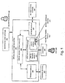
- Figure 1 illustrates an architecture of a virtual access control system, according to an example of the present disclosure
- Figure 2A illustrates a physical setup for the virtual access control system, according to an example of the present disclosure
- Figure 2B illustrates another physical setup for the virtual access control system, according to an example of the present disclosure
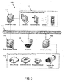
- Figure 3 illustrates technical architecture for the virtual access control system, according to an example of the present disclosure
- FIG. 4 illustrates a display for a monitoring graphical user interface (GUI) for the virtual access control system, according to an example of the present disclosure
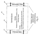
- Figure 5 illustrates an example of a layout for operation of video analytics for the virtual access control system, according to an example of the present disclosure
- Figure 6 illustrates a zone layout for the virtual access control system, according to an example of the present disclosure
- Figure 7 illustrates a virtual access control state diagram for the virtual access control system, according to an example of the present disclosure
- Figures 8A and 8B respectively illustrate empty and occupied states displayed on the GUI for the virtual access control system, according to an example of the present disclosure
- Figures 9A and 9B respectively illustrate accepted and rejected states displayed on the GUI for the virtual access control system, according to an example of the present disclosure
- Figures 10A and 10B respectively illustrate wrong way and error states displayed on the GUI for the virtual access control system, according to an example of the present disclosure
- Figures 11A, 11B and 11C illustrate stages of a single person accept scenario displayed on the GUI for the virtual access control system, according to an example of the present disclosure
- Figures 12A and 12B illustrate acceptable stages of a scenario for an unidentified single person, displayed on the GUI for the virtual access control system, according to an example of the present disclosure
- Figures 13A, 13B and 13C illustrate unacceptable stages of a scenario for an unidentified single person, displayed on the GUI for the virtual access control system, according to an example of the present disclosure
- Figures 14A-14D illustrate unacceptable stages of a scenario for rejection of authentication of a single person, displayed on the GUI for the virtual access control system, according to an example of the present disclosure
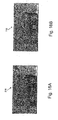
- Figures 15A, 15B and 15C illustrate acceptable stages of a scenario for rejection of authentication of a single person, displayed on the GUI for the virtual access control system, according to an example of the present disclosure
- Figures 16A and 16B illustrate acceptable stages of a scenario for a wrong way single person, displayed on the GUI for the virtual access control system, according to an example of the present disclosure
- Figures 17A, 17B and 17C illustrate unacceptable stages of a scenario for a wrong way single person, displayed on the GUI for the virtual access control system, according to an example of the present disclosure
- Figures 18A-18D illustrate stages of a tailgating scenario, displayed on the GUI for the virtual access control system, according to an example of the present disclosure
- Figures 19A, 19B and 19C illustrate stages of an error scenario, displayed on the GUI for the virtual access control system, according to an example of the present disclosure
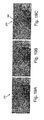
- Figure 20 illustrates generation of a three-dimensional (3D) model for a face captured from a uniform background, with frontal face deviation of generally less than approximately ⁇ 45° from front/center, and independence from facial expression, according to an example of the present disclosure
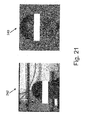
- Figure 21 illustrates generation of a 3D model for a face captured from a non-uniform background, with frontal face deviation of generally less than approximately ⁇ 30° from front/center, according to an example of the present disclosure
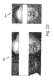
- Figure 22 illustrates generation of a 3D model of a face from multiple faces that are present within an image, according to an example of the present disclosure
- Figure 23 illustrates positioning of a 3D face of an individual adjacent a 2D image and/or a potential 2D probe image of the individual, according to an example of the present disclosure
- Figure 24 illustrates a flowchart of a method for virtual access control, according to an example of the present disclosure.
- Figure 25 illustrates a computer system, according to an example of the present disclosure.
- the terms “a” and “an” are intended to denote at least one of a particular element.
- the term “includes” means includes but not limited to, the term “including” means including but not limited to.
- the term “based on” means based at least in part on.
- a method for virtual access control disclosed herein may include detecting entry of a person into a virtual controlled zone, and counting and/or identifying people including the person entering into the virtual controlled zone.
- the method for virtual access control disclosed herein may further include determining, by a processor, an authorization of the person to continue through the virtual controlled zone based on a facial identification of the person, and alerting the person to stop, exit from (e.g., exit virtual controlled zone from entry point), or continue through the virtual controlled zone based on the determined authorization.
- An alarm may be generated if the person violates directions provided by the alert.
- a virtual access control system disclosed herein may include a memory storing machine readable instructions to detect entry of a person into a virtual controlled zone, and count and/or identify people including the person entering into the virtual controlled zone.
- the machine readable instructions may further determine an authorization of the person to continue through the virtual controlled zone based on a facial and/or an information based identification of the person, and alert the person to stop, exit from, or continue through the virtual controlled zone based on the determined authorization.
- the machine readable instructions may further generate an alarm if the person violates directions provided by the alert.
- a processor may implement the machine readable instructions.
- the virtual access control system provides a virtual access gate that may be less intrusive to operate and use for allowing authorized people to pass through an area.
- the virtual access gate also provides faster throughput compared to physical gates and doors, while still enforcing access control, flow control and counting.
- the virtual access gate may be used in conditions where a good approximation of entered users is necessary or in situations where access control is needed but security is not critical. Examples of such conditions may include fair and public event access areas, enterprise access to mid security critical areas, entering and leaving mass transit areas, boarding or leaving an airplane, and lounges of clubs, hotels, airports etc.
- the system and method described herein provide a technical solution to the technical problem of controlling access of people to a secured area.
- physical gates or doors are needed to control access of people to or from a secured area. Without such physical gates or doors, security personnel are typically used to control access of people to or from the secured area.
- the system and method described herein provide the technical solution of controlling access of people to or from a secured area without the need for such physical gates or doors, and without the need for security personnel. While security personnel may be used to monitor access of people to or from the secured area, the system and method guide entry and exit of people to or from the secured area, and provide for authentication of people before allowing entry into the secured area.
- FIG. 1 illustrates an architecture of a virtual access control system 100, according to an example of the present disclosure.
- the virtual access control system 100 may generally include a virtual access control module 101 to control operation of a feedback module 102, a video analytics module 103, and a decision module 104.
- the feedback module 102 may monitor and control operation of feedback devices 105, such as, for example, floor/wall lighting and audio feedback devices to indicate to people (e.g., user 106 of the virtual access control system 100) whether to stop, exit from, or continue through a secured area.
- the video analytics module 103 may include a virtual tripwire module 107 to detect when the user 106 has entered or departed from a monitoring zone of the virtual access control system 100.
- the video analytics module 103 may include a unicity module 108 to detect and count users 106 to ensure every user is positively identified before passing through a monitoring zone of the virtual access control system 100.
- the virtual tripwire module 107 and the unicity module 108 may use cameras 109 and other motion, face and/or user detection devices for the detection and counting of users 106.
- the decision module 104 may use authentication devices 110 for identity recognition of users 106.
- the authentication devices 110 may include kiosk-based devices for stop-and-interact identity recognition (e.g., scan e-passport, look at camera, other biometric identification techniques, etc.), or remotely positioned devices for on-the-fly identity recognition at a distance (e.g., a camera capturing and matching faces against a list of authorized users), which can apply to single users, or multiple users at the same time.
- a monitoring user interface 111 may include, for example, a graphical user interface (GUI) for facilitating supervision of operations and intervening by security personnel 112 in case of incidents (e.g., a user not recognized, a user going forward despite video/audio feedback to go back, or in exceptional situations etc.).
- GUI graphical user interface
- the modules and other elements of the system 100 may comprise machine readable instructions stored on a non-transitory computer readable medium.
- the modules and other elements of the system 100 may comprise hardware or a combination of machine readable instructions and hardware.
- FIG. 2A illustrates a physical setup 120 for the virtual access control system 100, according to an example of the present disclosure.
- the physical setup 120 may generally include the camera 109, the feedback devices 105 that include primary entry lights 121, primary exit lights 122, secondary exit lights 123, and secondary entry lights 124.
- the physical setup 120 may further include the authentication device 110, which is shown as a kiosk-based devices for stop-and-interact identity recognition of the user 106. Instead of the lights as shown, a variety of other methods may be used to provide feedback to a user. For example, other visible, audible or sensory devices may be used to provide user feedback.
- floor tiles with directional flow control lights may be added on the floor to control the flow of users 106 with red crosses to prohibit access and green arrows to allow access.
- one-half of the X 125 of Figure 2B may be highlighted in green or red (or in another color) to function as an arrow (e.g., with the arrow head shown) to respectively permit and prohibit movement in a predetermined direction.
- FIG. 3 illustrates technical architecture 140 for the virtual access control system 100, according to an example of the present disclosure.
- the technical architecture 140 may generally include a virtual gate host 141, which may provide for operation of the virtual access control module 101 to control operation of the feedback module 102, the video analytics module 103, and the decision module 104.
- the virtual gate host 141 may be connected by a communication bus 142 to a video analytics server 143 which may provide for operation of the video analytics module 103.
- a check-point host 144 may be provided for operation of the decision module 104 that uses authentication devices 110 for identity recognition.
- FIG 4 illustrates a display for the monitoring user interface 111 for the virtual access control system 100, according to an example of the present disclosure.
- the monitoring user interface 111 may generally include primary entry directional arrows 161 that correspond to the primary entry lights 121, primary exit directional arrows 162 that correspond to the primary exit lights 122, secondary exit directional arrows 163 that correspond to the secondary exit lights 123, and secondary entry directional arrows 164 that correspond to the secondary entry lights 124.
- the arrows 161-164 may be color coded, for example, green or red, to respectively allow or deny entry or exit.
- An alarm sign 165 may be displayed when an alarm is raised (e.g., access not allowed, wrong way or error alarm).
- An overcrowded sign 166 may be displayed when there is more than one user inside the area monitored and controlled by the virtual access control system 100.
- An accepted or rejected sign 167 may be displayed respectively as a check as shown in Figure 4 for authenticating a user or an "X" mark for denying authentication to a user based on feedback from the decision module 104.
- Figure 5 illustrates an example of a layout for operation of video analytics for the virtual access control system 100, according to an example of the present disclosure.
- the zone 180 may include primary and secondary sides 181, 182, respectively, where the user 106 may enter or exit.
- the primary side 181 may be designated based on a typical entry/exit point, whereas the secondary side 182 may be designated by a less frequently used or a prohibited entry/exit point.
- the virtual tripwire module 107 may monitor the primary and secondary sides 181, 182 of the zone 180 by setting triggers based on input from the camera 109 when a user crosses a virtual line of zones defined by the area of coverage of the primary and secondary sides 181, 182, in either direction (e.g., left or right side in the orientation of Figure 5 ).
- the primary side 181 allows a user to enter/exit the primary side of a virtual access gate operated by the virtual access control system 100.
- the secondary side 182 allows a user to enter/exit the secondary side of a virtual access gate operated by the virtual access control system 100.
- a central zone 183 may be designated where the unicity module 108 detects if the zone is either in an empty state, an occupied state (i.e., exactly one person in the central zone 183), or an over-crowded state (i.e., more than one person in the central zone 183).
- the central zone 183 thus facilitates the counting of the number of people inside a virtual access gate operated by the virtual access control system 100 and provides for display of information such as alarms, overcrowded alerts, decision feedback etc., at the monitoring user interface 111.
- the virtual access control system 100 may thus allow users to enter/exit from either the side 181 or the side 182, and exit accordingly, with the central zone 183 functioning in a similar manner as discussed herein.
- FIG. 6 illustrates a zone layout 200 for the virtual access control system 100, according to an example of the present disclosure.
- the zone layout 200 may generally include zones 1-4, which respectively correspond to the primary side 181 of Figure 5 , the central zone 183, the secondary side 182, and the zone of location of the authentication devices 110.
- the zone layout 200 may be used for facilitating operation of the virtual access control system 100, for example, by triggering feedback to security personnel 112 as to which zones require attention.
- the zone designations 1-4 may be used to provide feedback to the security personnel 112, where the security personnel 112 may readily recognize a zone of concern based a visual display at the monitoring user interface 111, or another form of audible signal that specifies a zone number (e.g. 1-4) for the zone of concern.
- the video analytics module 103 may include the unicity module 108 to detect and count people to ensure every individual is positively identified before passing through a monitoring zone (i.e., the central zone 183) of the virtual access control system 100.
- the unicity module 108 may detect and count people by using a predetermined average area of a person's head from a downward pointing camera 109 to determine how much total area of the central zone 183 is obscured. For example, if an average area covered by a person's head is X m 2 , then the unicity module 108 may determine the number of people in the central zone 183 by determining how much of the total area of the central zone 183 is obscured and dividing by the average area covered by a person's head.
- the unicity module 108 may also use an overall average area covered by a person's torso when viewed downwards to detect and count people.
- the unicity module 108 may also detect and count people based on detection of other body parts, such as, for example, shoulders etc.
- the unicity module 108 may operate in conjunction with a face-in-the crowd module 113 that detects faces of individuals to thus compare and confirm the detection of people based on comparison of a person's head.
- the unicity module 108 may operate in conjunction with the face-in-the crowd system described in co-ending and commonly owned U.S. Patent Application No. 13/753,847 titled "System and Method for Face Capture and Matching", the disclosure of which is incorporated by reference in its entirety.
- the virtual access control system 100 may also control a large or predetermined number of people based on the unicity module 108 by allowing a predetermined number of people to enter and depart from the central zone 183.
- the number of people that are counted entering and exiting the primary and secondary sides 181, 182, and within the central zone 183, may be used by the virtual access control module 101 as multiple accuracy checks at various points of operation of the virtual access control system 100.
- the unicity module 108 may also use other methods, such as, for example, counting the difference between enter and exit signals from the primary and secondary sides 181, 182, or detecting and counting distinct features of people (e.g., counting the number of ears or eyes visible).
- Figure 7 illustrates a virtual access control state diagram 220 for the virtual access control system 100, according to an example of the present disclosure.
- the state diagram 220 illustrates operational logic of the virtual access control system 100.
- the various states illustrated in the state diagram 220 are illustrated in Figures 8A-19C . Transitions in the state diagram 220 may begin at state 221, the empty state of the central zone 183 of Figure 5 .
- the different signals that may be received at the virtual access control module 101 from the feedback module 102, the video analytics module 103 and the decision module 104 include "Primary Enter”, “Primary Exit”, “Secondary Enter”, “Secondary Exit”, “Central Empty”, “Central Occupied”, “Central Over-Crowded”, “Decision Accept” and “Decision Deny”. Any alert generated at the monitoring user interface 111 is illustrated in parenthesis on the state diagram 220. For example, beginning at the empty state 221, a person entering from the primary side 181 of Figure 5 triggers a Primary Enter signal and the virtual access control module 101 proceeds to entering primary side state 222.
- the primary exit lights 122 of Figure 2A may be highlighted green and the remaining lights may be highlighted red.
- a Decision Accept signal is detect, this means that the person was properly authenticated by the decision module 104, and the virtual access control module 101 proceeds to accepted state 225.
- the secondary exit lights 123 of Figure 2A may be highlighted green and the remaining lights may be highlighted red.
- Figures 8A and 8B respectively illustrate empty and occupied states displayed on the monitoring user interface 111 for the virtual access control system 100, according to an example of the present disclosure.
- the empty state illustration of Figure 8A corresponds to the empty state 221 where no one is within the monitoring zone of the virtual access control system 100.
- a user 106 may enter from the primary side 181 of Figure 5 .
- the primary entry lights 121 of Figure 2A may be highlighted green and the remaining lights may be highlighted red.
- the occupied state illustration of Figure 8B corresponds to the unauthenticated state 223, as well as the accepted and denied states 225 and 227 where a person is still present in the central zone 183.
- the occupied state illustration of Figure 8B also corresponds to over-crowded state 228 if multiple people are within the central zone 183.
- a user is within the monitoring zone of the virtual access control system 100. If the user is not identified, the user is allowed to go back, and no one else is allowed to enter the monitoring zone of the virtual access control system 100.
- the primary exit lights 122 of Figure 2A may be highlighted green and the remaining lights may be highlighted red.
- Figures 9A and 9B respectively illustrate accepted and rejected states displayed on the monitoring user interface 111 for the virtual access control system 100, according to an example of the present disclosure.
- the accepted state illustration corresponds to the accepted state 225 of the virtual access control module 101.
- a user inside the central zone 183 has been identified and may exit through the secondary side 182. No one else is allowed to enter the monitoring zone of the virtual access control system 100.
- the secondary exit lights 123 of Figure 2A may be highlighted green and the remaining lights may be highlighted red.
- the rejected state illustration corresponds to the denied state 227 of the virtual access control module 101.
- a user inside the central zone 183 has not been identified and may not exit through the secondary side 182, but has to return through the primary side 181. No one else is allowed to enter the monitoring zone of the virtual access control system 100.
- the primary exit lights 122 of Figure 2A may be highlighted green and the remaining lights may be highlighted red.
- Figures 10A and 10B respectively illustrate wrong way and error states displayed on the monitoring user interface 111 for the virtual access control system 100, according to an example of the present disclosure.
- the wrong way state illustration corresponds to an enter wrong way state 229 of the virtual access control module 101.
- a user enters the central zone 183 from the secondary side 182 and must exit through the secondary side 182.
- the secondary exit lights 123 of Figure 2A may be highlighted green and the remaining lights may be highlighted red.
- the error state illustration corresponds to error state 230 of the virtual access control module 101.
- people may be entering from both the primary and secondary sides 181, 182, and meeting in the central zone 183. No one is allowed to exit the monitoring zone of the virtual access control system 100 unless permission is granted by the security personnel 112. All lights of Figure 2A may be red to prevent entry or exit.
- Figures 12A and 12B illustrate acceptable stages of a scenario for an unidentified single person, displayed on the monitoring user interface 111 for the virtual access control system 100, according to an example of the present disclosure.
- a single person e.g., the user 106 enters the central zone 183 from the primary side 181, which corresponds to the entering primary side state 222.
- the primary entry lights 121 of Figure 2A may be highlighted green and the remaining lights may be highlighted red.
- the person may stop in the central zone 183 and exit from the primary side 181, which corresponds to the leaving unauthenticated state 224.
- the primary exit lights 122 of Figure 2A may be highlighted green and the remaining lights may be highlighted red.
- the person exits from the primary side 181, which triggers a Primary Exit signal and corresponds to the empty state 221.
- This scenario triggers no alerts at the monitoring user interface 111.
- Figures 13A, 13B and 13C illustrate unacceptable stages of a scenario for an unidentified single person, displayed on the monitoring user interface 111 for the virtual access control system 100, according to an example of the present disclosure.
- a single person enters the central zone 183 from the primary side 181, which corresponds to the entering primary side state 222. Initially, the primary entry lights 121 of Figure 2A may be highlighted green and the remaining lights may be highlighted red.
- the person continues through the central zone 183 without stopping and exits through the secondary side 182. This triggers the alarm sign 165 (see Figure 4 ).
- the person's progress from the entering primary side state 222 to the exit from the secondary side 182 corresponds to the unauthenticated state 223 and the leaving unauthenticated state 224 after which a Secondary Exit signal triggers a TRESSPASSING alert on the monitoring user interface 111.
- Figures 14A-14D illustrate unacceptable stages of a scenario for rejection of authentication of a single person, displayed on the monitoring user interface 111 for the virtual access control system 100, according to an example of the present disclosure.
- a single person enters the central zone 183 from the primary side 181, which corresponds to the entering primary side state 222. Initially, the primary entry lights 121 of Figure 2A may be highlighted green and the remaining lights may be highlighted red.
- the person stops at the central zone 183 for authentication, which corresponds to the unauthenticated state 223 of Figure 7 .
- the person's entry is rejected by the decision module 104, which corresponds to the denied state 227 of Figure 7 .
- the primary exit lights 122 of Figure 2A may be highlighted green and the remaining lights may be highlighted red.
- the person's exit from the secondary side 182 corresponds to a leaving denied state 231 after which a Secondary Exit signal triggers a DENIED ENTRY alert on the monitoring user interface 111.
- Figures 15A, 15B and 15C illustrate acceptable stages of a scenario for rejection of authentication of a single person, displayed on the monitoring user interface 111 for the virtual access control system 100, according to an example of the present disclosure.
- a single person enters the central zone 183 from the primary side 181, which corresponds to the entering primary side state 222. Initially, the primary entry lights 121 of Figure 2A may be highlighted green and the remaining lights may be highlighted red.
- the person stops at the central zone 183 for authentication, which corresponds to the unauthenticated state 223 of Figure 7 .
- the person's entry is rejected by the decision module 104, which corresponds to the denied state 227 of Figure 7 .
- the primary exit lights 122 of Figure 2A may be highlighted green and the remaining lights may be highlighted red.
- the person's exit from the primary side 181 corresponds to a leaving denied state 231 after which a Primary Exit signal indicates that no alarm is to be triggered.
- Figures 16A and 16B illustrate acceptable stages of a scenario for a wrong way single person, displayed on the monitoring user interface 111 for the virtual access control system 100, according to an example of the present disclosure.
- a single person enters the central zone 183 from the secondary side 182, which corresponds to the enter wrong way state 229.
- the primary entry lights 121 of Figure 2A may be highlighted green and the remaining lights may be highlighted red.
- the secondary exit lights 123 of Figure 2A may be highlighted green and the remaining lights may be highlighted red.
- the person's exit from the secondary side 182 corresponds to a halfway wrong way state 232, then a leaving wrong way state 233, after which a Secondary Exit signal indicates that no alarm is to be triggered.
- Figures 17A, 17B and 17C illustrate unacceptable stages of a scenario for a wrong way single person, displayed on the monitoring user interface 111 for the virtual access control system 100, according to an example of the present disclosure.
- a single person enters the central zone 183 from the secondary side 182, which corresponds to the enter wrong way state 229.
- the primary entry lights 121 of Figure 2A may be highlighted green and the remaining lights may be highlighted red.
- the secondary exit lights 123 of Figure 2A may be highlighted green and the remaining lights may be highlighted red.
- a WRONG WAY alert is triggered.
- the person's exit from the primary side 181 corresponds to the halfway wrong way state 232, then the leaving wrong way state 233, after which a Primary Exit signal triggers a WRONG WAY alert at the monitoring user interface 111.
- Figures 18A-18D illustrate stages of a tailgating scenario, displayed on the monitoring user interface 111 for the virtual access control system 100, according to an example of the present disclosure.
- a single person enters the central zone 183 from the primary side 181, which corresponds to the entering primary side state 222. Initially, the primary entry lights 121 of Figure 2A may be highlighted green and the remaining lights may be highlighted red.
- the person stops at the central zone 183 for authentication, which corresponds to the unauthenticated state 223 of Figure 7 .
- a second person enters from the primary side 181, which triggers an overcrowded sign 166 (see Figure 4 ), and further an alarm sign 165 as shown in Figure 18C on the monitoring user interface 111.
- the overcrowded and alarm signs correspond to the error state 230 of Figure 7 .
- the person's entry is rejected by the decision module 104, and an OVER CROWDED alert may be raised.
- the first person may engage the authentication device 110 to re-start the identification process.
- FIGS 19A, 19B and 19C illustrate stages of an error scenario, displayed on the monitoring user interface 111 for the virtual access control system 100, according to an example of the present disclosure.
- a single person enters the central zone 183 from the primary side 181, which corresponds to the entering primary side state 222. Initially, the primary entry lights 121 of Figure 2A may be highlighted green and the remaining lights may be highlighted red. Once the person enters the central zone 183, at Figure 19B , the primary exit lights 122 of Figure 2A may be highlighted green and the remaining lights may be highlighted red.
- Figure 19C another person enters the central zone 183 form the secondary side 182. This triggers an overcrowded sign 166 on the monitoring user interface 111. For Figure 19C , all lights of Figure 2A may be highlighted red.
- This scenario corresponds to the error state 230 of Figure 7 and an OVER CROWDED alert may be raised on the monitoring user interface 111.
- the unicity module 108 may operate in conjunction with the face-in-the crowd module 113 that detects faces of individuals to thus compare and confirm the detection of people based on comparison of a person's head. Additionally or alternatively, with respect to detection of faces of individuals, the unicity module 108 may also operate in conjunction with a three-dimensional (3D) face modeling module 114 that generates frontal images from angled faces through a 3D face modeling process.
- the 3D face modeling module 114 may use, for example, the CYBER EXTRUDER AUREUS 3D face modeling process for generation of 3D face models.
- the 3D face modeling process may be used as a pre-processing step for face recognition by the face-in-the crowd module 113. Further, the 3D face modeling process may be used for human adjudication as well as for face detection based on 3D modeling.
- the 3D face modeling module 114 may be used as a pre-processing step for the face-in-the crowd module 113 that uses 2D images for face detection for frontal faces that are obtained from a uniform background (e.g., a white, or single color background), with frontal face deviation of generally less than approximately ⁇ 45° from front/center, and independent of facial expression.
- a uniform background e.g., a white, or single color background
- the 3D face modeling module 114 may be used as a pre-processing step for the face-in-the crowd module 113 for a frontal face 240 that is obtained from a uniform background, with frontal face deviation of generally less than approximately ⁇ 45° from front/center, and independent of facial expression, to generate a 3D model 241.
- the 3D face modeling module 114 may be used as a pre-processing step for the face-in-the crowd module 113 for frontal faces that are disposed at less than approximately ⁇ 30° from front/center.
- the 3D face modeling module 114 may be used as a pre-processing step for the face-in-the crowd module 113 for a frontal face 242 that is disposed at less than approximately ⁇ 30° from front/center to generate a 3D model 243.
- the 3D face modeling module 114 may also be used to generate a 3D model of a face from multiple faces that are present within an image. For example, as shown in Figure 22 , the 3D face modeling module 114 may be used to generate a 3D model 244 of a face from multiple faces that are present within an image 245.
- the 3D face modeling module 114 may be used to generate a 3D face to facilitate human adjudication of faces detected by the face-in-the crowd module 113.
- the monitoring user interface 111 may include a GUI for facilitating supervision of operations and intervening by security personnel 112 in case of incidents (e.g., a user not recognized, a user going forward despite video/audio feedback to go back, or in exceptional situations etc.).
- the 3D face modeling module 114 may provide for adjudication by the security personnel 112, for example, by positioning a reconstructed 3D face of an individual (e.g., the user 106) in the same angle as a potential 2D probe image of the individual.
- the probe image of the individual may be defined as an image taken at a predetermined angle and under predetermined environmental conditions (e.g., uniform background). Additionally or alternatively, the 3D face modeling module 114 may provide for adjudication by the security personnel 112, for example, by positioning a 3D face of an individual adjacent a 2D image and/or a potential 2D probe image of the individual. For example, as shown in Figure 23 , the 3D face modeling module 114 may provide for adjudication by the security personnel 112, for example, by positioning a 3D face 246 of an individual adjacent a potential 2D probe image 247 of the individual.
- Figure 24 illustrates a flowchart of a method 300 for virtual access control, corresponding to the example of the virtual access control system 100 whose construction is described in detail above.
- the method 300 may be implemented on the virtual access control system 100 with reference to Figures 1-23 by way of example and not limitation. The method 300 may be practiced in other systems.
- the method may include detecting entry of a person into a virtual controlled zone.
- the virtual tripwire module 107 may detect when the user 106 has entered or departed from a monitoring zone (e.g., the virtual controlled zone) of the virtual access control system 100.
- the method may include counting and/or identifying people including the person entering into the virtual controlled zone.
- the unicity module 108 may detect and count users 106 to ensure every user is positively identified before passing through a monitoring zone of the virtual access control system 100.
- the virtual tripwire module 107 and the unicity module 108 may use cameras 109 and other motion, face and/or user detection devices for the detection and counting of users 106.
- the method may include determining an authorization of the person to continue through the virtual controlled zone based on a facial identification of the person.
- the decision module 104 may use authentication devices 110 for identity recognition of users 106.
- the authentication devices 110 may include kiosk-based devices for stop-and-interact identity recognition (e.g., scan e-passport, look at camera, other biometric identification, etc.), or remotely positioned devices for on-the-fly identity recognition at a distance (e.g., a camera capturing and matching faces against a list of authorized users), which can apply to single users, or multiple users at the same time.
- the method may include alerting the person to stop, exit from, or continue through the virtual controlled zone based on the determined authorization.
- the feedback module 102 may monitor and control operation of feedback devices 105, such as, for example, floor/wall lighting and audio feedback devices to indicate to people (e.g., user 106 of the virtual access control system 100) whether to stop, exit from, or continue through a secured area.
- the method may include generating an alarm if the person violates directions provided by the alert.
- alerting the person to stop, exit from, or continue through the virtual controlled zone may further include displaying arrows and/or crosses on a GUI (e.g., monitoring user interface 111) in predetermined directions and in predetermined colors to alert the person to stop, exit from, or continue through the virtual controlled zone.
- GUI e.g., monitoring user interface 111
- alerting the person to stop, exit from, or continue through the virtual controlled zone may further include using floor lighting, wall lighting, and/or an audible signal to alert the person to stop, exit from, or continue through the virtual controlled zone.
- alerting the person to stop, exit from, or continue through the virtual controlled zone may further include using wall lighting that includes primary entry and exit lights disposed adjacent a primary entry location of the virtual controlled zone, and using secondary entry and exit lights disposed adjacent a secondary entry location of the virtual controlled zone that is disposed generally opposite to the primary entry location.
- alerting the person to stop, exit from, or continue through the virtual controlled zone may further include using floor lighting that forms arrows and/or crosses in predetermined directions and in predetermined colors to alert the person to stop, exit from, or continue through the virtual controlled zone.
- alerting the person to stop, exit from, or continue through the virtual controlled zone may further include displaying a symbol on a GUI to indicate an overcrowded state of the virtual controlled zone.
- alerting the person to stop, exit from, or continue through the virtual controlled zone may further include determining a state of occupancy of the virtual controlled zone, and generating different alerts for the person to stop, exit from, or continue through the virtual controlled zone based on different states of occupancy including the state of occupancy of the virtual controlled zone.
- the different states of occupancy may include a state of occupancy including a primary enter state into the virtual controlled zone, a primary exit state from the virtual controlled zone, a central empty state for the virtual controlled zone, a central occupied state for the virtual controlled zone, a central over-crowded state for the virtual controlled zone, a decision accept state based on the determined authorization to allow the person to continue through the virtual controlled zone, and/or a decision deny state based on the determined authorization to deny the person from continuing through the virtual controlled zone.
- generating an alarm if the person violates directions provided by the alert may further include generating a visual or audible alarm if the person violates directions provided by the alert.
- counting people including the person entering into the virtual controlled zone may further include determining an area of the person's head in a downward direction, comparing the area of the person's head to an area of the virtual controlled zone, and determining a number of people in the virtual controlled zone based on the comparison.
- counting people including the person entering into the virtual controlled zone may further include determining a difference between entry and exit signals of the people that respectively enter and exit the virtual controlled zone.
- identifying people including the person entering into the virtual controlled zone may further include comparing a 2D image of the face of the person against previously captured images of faces of people, and identifying the person based on a match of the 2D image of the face of the person to one of the previously captured images of faces of people.
- identifying people including the person entering into the virtual controlled zone may further include capturing a 2D image of the face of the person by using a camera, determining an angle of the face of the person relative to a central axis of the camera, determining if the angle of the face of the person is less than or equal to a predetermined threshold relative to the central axis of the camera, based on a determination that the angle of the face of the person is less than or equal to the predetermined threshold, converting the 2D image to a 3D image model, and using the 3D image model to identify the person based on a match of the 3D image model to one of the previously captured 2D images of faces of people.
- the predetermined threshold may be approximately ⁇ 45° relative to the central axis of the camera.
- using the 3D image model to identify the person based on a match of the 3D image model to one of the previously captured 2D images of faces of people may further include rotating the 3D image model to an angle approximately equal to the angle of the face of the person in the 2D image of the face of the person, and analyzing the rotated 3D image model to determine if the rotated 3D image model matches one of the previously captured 2D images of faces of people.
- identifying people including the person entering into the virtual controlled zone may further include capturing a 2D image of the face of the person by using a camera, determining an angle of the face of the person relative to a central axis of the camera, determining if the angle of the face of the person is less than or equal to a predetermined threshold relative to the central axis of the camera, based on a determination that the angle of the face of the person is less than or equal to the predetermined threshold, converting the 2D image to a 3D image model, rotating the 3D image model to an angle approximately equal to the central axis of the camera, generating a 2D image based on the rotated 3D model, comparing the generated 2D image against previously captured images of faces of people, and identifying the person based on a match of the generated 2D image of the face of the person to one of the previously captured 2D images of faces of people.
- the predetermined threshold may be approximately ⁇ 30° relative to the central axis of the camera for a uniform background and
- identifying people including the person entering into the virtual controlled zone may further include using the 3D image model to further identify the person based on a match of the 3D image model to one of the previously captured 2D images of faces of people.
- Figure 25 shows a computer system 400 that may be used with the examples described herein.
- the computer system 400 represents a generic platform that may include components that may be in a server or another computer system.
- the computer system 400 may be used as a platform for the system 100.
- the computer system 400 may execute, by a processor or other hardware processing circuit, the methods, functions and other processes described herein. These methods, functions and other processes may be embodied as machine readable instructions stored on computer readable medium, which may be non-transitory, such as hardware storage devices (e.g., RAM (random access memory), ROM (read only memory), EPROM (erasable, programmable ROM), EEPROM (electrically erasable, programmable ROM), hard drives, and flash memory).
- RAM random access memory
- ROM read only memory
- EPROM erasable, programmable ROM
- EEPROM electrically erasable, programmable ROM
- hard drives and flash memory
- the computer system 400 includes a processor 402 that may implement or execute machine readable instructions performing some or all of the methods, functions and other processes described herein. Commands and data from the processor 402 are communicated over a communication bus 404.
- the computer system 400 also includes a main memory 406, such as a random access memory (RAM), where the machine readable instructions and data for the processor 402 may reside during runtime, and a secondary data storage 408, which may be nonvolatile and stores machine readable instructions and data.
- the memory and data storage are examples of computer readable mediums.
- the memory 406 may include modules 420 including machine readable instructions residing in the memory 406 during runtime and executed by the processor 402.
- the modules 420 may include the modules of the system 100 shown in Figures 1-23 .
- the computer system 400 may include an I/O device 410, such as a keyboard, a mouse, a display, etc.
- the computer system 400 may include a network interface 412 for connecting to a network.
- Other known electronic components may be added or substituted in the computer system 400.
Landscapes
- Engineering & Computer Science (AREA)
- Physics & Mathematics (AREA)
- General Physics & Mathematics (AREA)
- Multimedia (AREA)
- Theoretical Computer Science (AREA)
- Human Computer Interaction (AREA)
- Health & Medical Sciences (AREA)
- General Health & Medical Sciences (AREA)
- Oral & Maxillofacial Surgery (AREA)
- Signal Processing (AREA)
- Alarm Systems (AREA)
Abstract
Description
- Detection and control of entry of people into a secured area typically requires setup of infrastructure that can include controlled passages with locked gates or doors. The locked gates or doors can cause delay in entry or exit of people, for example, if a large number of people are to enter and exit through an area. Thus, such types of infrastructure can limit throughput, and in certain environments, setup of such physical infrastructure can be prohibitive.
- Features of the present disclosure are illustrated by way of examples shown in the following figures. In the following figures, like numerals indicate like elements, in which:
-
Figure 1 illustrates an architecture of a virtual access control system, according to an example of the present disclosure; -
Figure 2A illustrates a physical setup for the virtual access control system, according to an example of the present disclosure; -
Figure 2B illustrates another physical setup for the virtual access control system, according to an example of the present disclosure; -
Figure 3 illustrates technical architecture for the virtual access control system, according to an example of the present disclosure; -
Figure 4 illustrates a display for a monitoring graphical user interface (GUI) for the virtual access control system, according to an example of the present disclosure; -
Figure 5 illustrates an example of a layout for operation of video analytics for the virtual access control system, according to an example of the present disclosure; -
Figure 6 illustrates a zone layout for the virtual access control system, according to an example of the present disclosure; -
Figure 7 illustrates a virtual access control state diagram for the virtual access control system, according to an example of the present disclosure; -
Figures 8A and 8B respectively illustrate empty and occupied states displayed on the GUI for the virtual access control system, according to an example of the present disclosure; -
Figures 9A and 9B respectively illustrate accepted and rejected states displayed on the GUI for the virtual access control system, according to an example of the present disclosure; -
Figures 10A and 10B respectively illustrate wrong way and error states displayed on the GUI for the virtual access control system, according to an example of the present disclosure; -
Figures 11A, 11B and 11C illustrate stages of a single person accept scenario displayed on the GUI for the virtual access control system, according to an example of the present disclosure; -
Figures 12A and 12B illustrate acceptable stages of a scenario for an unidentified single person, displayed on the GUI for the virtual access control system, according to an example of the present disclosure; -
Figures 13A, 13B and 13C illustrate unacceptable stages of a scenario for an unidentified single person, displayed on the GUI for the virtual access control system, according to an example of the present disclosure; -
Figures 14A-14D illustrate unacceptable stages of a scenario for rejection of authentication of a single person, displayed on the GUI for the virtual access control system, according to an example of the present disclosure; -
Figures 15A, 15B and 15C illustrate acceptable stages of a scenario for rejection of authentication of a single person, displayed on the GUI for the virtual access control system, according to an example of the present disclosure; -
Figures 16A and 16B illustrate acceptable stages of a scenario for a wrong way single person, displayed on the GUI for the virtual access control system, according to an example of the present disclosure; -
Figures 17A, 17B and 17C illustrate unacceptable stages of a scenario for a wrong way single person, displayed on the GUI for the virtual access control system, according to an example of the present disclosure; -
Figures 18A-18D illustrate stages of a tailgating scenario, displayed on the GUI for the virtual access control system, according to an example of the present disclosure; -
Figures 19A, 19B and 19C illustrate stages of an error scenario, displayed on the GUI for the virtual access control system, according to an example of the present disclosure; -
Figure 20 illustrates generation of a three-dimensional (3D) model for a face captured from a uniform background, with frontal face deviation of generally less than approximately ±45° from front/center, and independence from facial expression, according to an example of the present disclosure; -
Figure 21 illustrates generation of a 3D model for a face captured from a non-uniform background, with frontal face deviation of generally less than approximately ±30° from front/center, according to an example of the present disclosure; -
Figure 22 illustrates generation of a 3D model of a face from multiple faces that are present within an image, according to an example of the present disclosure; -
Figure 23 illustrates positioning of a 3D face of an individual adjacent a 2D image and/or a potential 2D probe image of the individual, according to an example of the present disclosure; -
Figure 24 illustrates a flowchart of a method for virtual access control, according to an example of the present disclosure; and -
Figure 25 illustrates a computer system, according to an example of the present disclosure. - For simplicity and illustrative purposes, the present disclosure is described by referring mainly to examples thereof. In the following description, numerous specific details are set forth in order to provide a thorough understanding of the present disclosure. It will be readily apparent however, that the present disclosure may be practiced without limitation to these specific details. In other instances, some methods and structures have not been described in detail so as not to unnecessarily obscure the present disclosure.
- Throughout the present disclosure, the terms "a" and "an" are intended to denote at least one of a particular element. As used herein, the term "includes" means includes but not limited to, the term "including" means including but not limited to. The term "based on" means based at least in part on.
- According to an example, a method for virtual access control disclosed herein may include detecting entry of a person into a virtual controlled zone, and counting and/or identifying people including the person entering into the virtual controlled zone. The method for virtual access control disclosed herein may further include determining, by a processor, an authorization of the person to continue through the virtual controlled zone based on a facial identification of the person, and alerting the person to stop, exit from (e.g., exit virtual controlled zone from entry point), or continue through the virtual controlled zone based on the determined authorization. An alarm may be generated if the person violates directions provided by the alert.
- According to another example, a virtual access control system disclosed herein may include a memory storing machine readable instructions to detect entry of a person into a virtual controlled zone, and count and/or identify people including the person entering into the virtual controlled zone. The machine readable instructions may further determine an authorization of the person to continue through the virtual controlled zone based on a facial and/or an information based identification of the person, and alert the person to stop, exit from, or continue through the virtual controlled zone based on the determined authorization. The machine readable instructions may further generate an alarm if the person violates directions provided by the alert. A processor may implement the machine readable instructions.
- The virtual access control system provides a virtual access gate that may be less intrusive to operate and use for allowing authorized people to pass through an area. The virtual access gate also provides faster throughput compared to physical gates and doors, while still enforcing access control, flow control and counting. The virtual access gate may be used in conditions where a good approximation of entered users is necessary or in situations where access control is needed but security is not critical. Examples of such conditions may include fair and public event access areas, enterprise access to mid security critical areas, entering and leaving mass transit areas, boarding or leaving an airplane, and lounges of clubs, hotels, airports etc.
- The system and method described herein provide a technical solution to the technical problem of controlling access of people to a secured area. In many instances, physical gates or doors are needed to control access of people to or from a secured area. Without such physical gates or doors, security personnel are typically used to control access of people to or from the secured area. The system and method described herein provide the technical solution of controlling access of people to or from a secured area without the need for such physical gates or doors, and without the need for security personnel. While security personnel may be used to monitor access of people to or from the secured area, the system and method guide entry and exit of people to or from the secured area, and provide for authentication of people before allowing entry into the secured area.
-
Figure 1 illustrates an architecture of a virtualaccess control system 100, according to an example of the present disclosure. The virtualaccess control system 100 may generally include a virtualaccess control module 101 to control operation of afeedback module 102, avideo analytics module 103, and adecision module 104. Thefeedback module 102 may monitor and control operation offeedback devices 105, such as, for example, floor/wall lighting and audio feedback devices to indicate to people (e.g.,user 106 of the virtual access control system 100) whether to stop, exit from, or continue through a secured area. Thevideo analytics module 103 may include avirtual tripwire module 107 to detect when theuser 106 has entered or departed from a monitoring zone of the virtualaccess control system 100. Thevideo analytics module 103 may include aunicity module 108 to detect and countusers 106 to ensure every user is positively identified before passing through a monitoring zone of the virtualaccess control system 100. Thevirtual tripwire module 107 and theunicity module 108 may usecameras 109 and other motion, face and/or user detection devices for the detection and counting ofusers 106. Thedecision module 104 may useauthentication devices 110 for identity recognition ofusers 106. For example, theauthentication devices 110 may include kiosk-based devices for stop-and-interact identity recognition (e.g., scan e-passport, look at camera, other biometric identification techniques, etc.), or remotely positioned devices for on-the-fly identity recognition at a distance (e.g., a camera capturing and matching faces against a list of authorized users), which can apply to single users, or multiple users at the same time. Amonitoring user interface 111 may include, for example, a graphical user interface (GUI) for facilitating supervision of operations and intervening bysecurity personnel 112 in case of incidents (e.g., a user not recognized, a user going forward despite video/audio feedback to go back, or in exceptional situations etc.). - As described herein, the modules and other elements of the
system 100 may comprise machine readable instructions stored on a non-transitory computer readable medium. In addition, or alternatively, the modules and other elements of thesystem 100 may comprise hardware or a combination of machine readable instructions and hardware. -
Figure 2A illustrates aphysical setup 120 for the virtualaccess control system 100, according to an example of the present disclosure. Thephysical setup 120 may generally include thecamera 109, thefeedback devices 105 that include primary entry lights 121, primary exit lights 122, secondary exit lights 123, and secondary entry lights 124. Thephysical setup 120 may further include theauthentication device 110, which is shown as a kiosk-based devices for stop-and-interact identity recognition of theuser 106. Instead of the lights as shown, a variety of other methods may be used to provide feedback to a user. For example, other visible, audible or sensory devices may be used to provide user feedback. For example, as shown inFigure 2B , floor tiles with directional flow control lights may be added on the floor to control the flow ofusers 106 with red crosses to prohibit access and green arrows to allow access. For example, one-half of theX 125 ofFigure 2B may be highlighted in green or red (or in another color) to function as an arrow (e.g., with the arrow head shown) to respectively permit and prohibit movement in a predetermined direction. -
Figure 3 illustratestechnical architecture 140 for the virtualaccess control system 100, according to an example of the present disclosure. Thetechnical architecture 140 may generally include avirtual gate host 141, which may provide for operation of the virtualaccess control module 101 to control operation of thefeedback module 102, thevideo analytics module 103, and thedecision module 104. Thevirtual gate host 141 may be connected by acommunication bus 142 to avideo analytics server 143 which may provide for operation of thevideo analytics module 103. A check-point host 144 may be provided for operation of thedecision module 104 that usesauthentication devices 110 for identity recognition. -
Figure 4 illustrates a display for themonitoring user interface 111 for the virtualaccess control system 100, according to an example of the present disclosure. Referring toFigures 2A and4 , themonitoring user interface 111 may generally include primary entrydirectional arrows 161 that correspond to the primary entry lights 121, primary exitdirectional arrows 162 that correspond to the primary exit lights 122, secondary exitdirectional arrows 163 that correspond to the secondary exit lights 123, and secondary entrydirectional arrows 164 that correspond to the secondary entry lights 124. The arrows 161-164 may be color coded, for example, green or red, to respectively allow or deny entry or exit. Analarm sign 165 may be displayed when an alarm is raised (e.g., access not allowed, wrong way or error alarm). Anovercrowded sign 166 may be displayed when there is more than one user inside the area monitored and controlled by the virtualaccess control system 100. An accepted or rejectedsign 167 may be displayed respectively as a check as shown inFigure 4 for authenticating a user or an "X" mark for denying authentication to a user based on feedback from thedecision module 104. -
Figure 5 illustrates an example of a layout for operation of video analytics for the virtualaccess control system 100, according to an example of the present disclosure. For azone 180 monitored and controlled by the virtualaccess control system 100, thezone 180 may include primary andsecondary sides user 106 may enter or exit. Theprimary side 181 may be designated based on a typical entry/exit point, whereas thesecondary side 182 may be designated by a less frequently used or a prohibited entry/exit point. Thevirtual tripwire module 107 may monitor the primary andsecondary sides zone 180 by setting triggers based on input from thecamera 109 when a user crosses a virtual line of zones defined by the area of coverage of the primary andsecondary sides Figure 5 ). Theprimary side 181 allows a user to enter/exit the primary side of a virtual access gate operated by the virtualaccess control system 100. Thesecondary side 182 allows a user to enter/exit the secondary side of a virtual access gate operated by the virtualaccess control system 100. Acentral zone 183 may be designated where theunicity module 108 detects if the zone is either in an empty state, an occupied state (i.e., exactly one person in the central zone 183), or an over-crowded state (i.e., more than one person in the central zone 183). Thecentral zone 183 thus facilitates the counting of the number of people inside a virtual access gate operated by the virtualaccess control system 100 and provides for display of information such as alarms, overcrowded alerts, decision feedback etc., at themonitoring user interface 111. For bi-directional operation of the virtual access control system 100 (i.e., sides 181 and 182 are both designated primary entry/exit sides), the virtualaccess control system 100 may thus allow users to enter/exit from either theside 181 or theside 182, and exit accordingly, with thecentral zone 183 functioning in a similar manner as discussed herein. -
Figure 6 illustrates azone layout 200 for the virtualaccess control system 100, according to an example of the present disclosure. Thezone layout 200 may generally include zones 1-4, which respectively correspond to theprimary side 181 ofFigure 5 , thecentral zone 183, thesecondary side 182, and the zone of location of theauthentication devices 110. Thezone layout 200 may be used for facilitating operation of the virtualaccess control system 100, for example, by triggering feedback tosecurity personnel 112 as to which zones require attention. For example, the zone designations 1-4 may be used to provide feedback to thesecurity personnel 112, where thesecurity personnel 112 may readily recognize a zone of concern based a visual display at themonitoring user interface 111, or another form of audible signal that specifies a zone number (e.g. 1-4) for the zone of concern. - As discussed above, the
video analytics module 103 may include theunicity module 108 to detect and count people to ensure every individual is positively identified before passing through a monitoring zone (i.e., the central zone 183) of the virtualaccess control system 100. Referring toFigure 5 , theunicity module 108 may detect and count people by using a predetermined average area of a person's head from adownward pointing camera 109 to determine how much total area of thecentral zone 183 is obscured. For example, if an average area covered by a person's head is X m2, then theunicity module 108 may determine the number of people in thecentral zone 183 by determining how much of the total area of thecentral zone 183 is obscured and dividing by the average area covered by a person's head. Alternatively, theunicity module 108 may also use an overall average area covered by a person's torso when viewed downwards to detect and count people. Theunicity module 108 may also detect and count people based on detection of other body parts, such as, for example, shoulders etc. Theunicity module 108 may operate in conjunction with a face-in-thecrowd module 113 that detects faces of individuals to thus compare and confirm the detection of people based on comparison of a person's head. For example, theunicity module 108 may operate in conjunction with the face-in-the crowd system described in co-ending and commonly ownedU.S. Patent Application No. 13/753,847 titled "System and Method for Face Capture and Matching", the disclosure of which is incorporated by reference in its entirety. The virtualaccess control system 100 may also control a large or predetermined number of people based on theunicity module 108 by allowing a predetermined number of people to enter and depart from thecentral zone 183. The number of people that are counted entering and exiting the primary andsecondary sides central zone 183, may be used by the virtualaccess control module 101 as multiple accuracy checks at various points of operation of the virtualaccess control system 100. Theunicity module 108 may also use other methods, such as, for example, counting the difference between enter and exit signals from the primary andsecondary sides -
Figure 7 illustrates a virtual access control state diagram 220 for the virtualaccess control system 100, according to an example of the present disclosure. The state diagram 220 illustrates operational logic of the virtualaccess control system 100. The various states illustrated in the state diagram 220 are illustrated inFigures 8A-19C . Transitions in the state diagram 220 may begin atstate 221, the empty state of thecentral zone 183 ofFigure 5 . The different signals that may be received at the virtualaccess control module 101 from thefeedback module 102, thevideo analytics module 103 and thedecision module 104 include "Primary Enter", "Primary Exit", "Secondary Enter", "Secondary Exit", "Central Empty", "Central Occupied", "Central Over-Crowded", "Decision Accept" and "Decision Deny". Any alert generated at themonitoring user interface 111 is illustrated in parenthesis on the state diagram 220. For example, beginning at theempty state 221, a person entering from theprimary side 181 ofFigure 5 triggers a Primary Enter signal and the virtualaccess control module 101 proceeds to enteringprimary side state 222. Once the person is in thecentral zone 183, this triggers a Central Occupied signal, at which time the person is considered unauthenticated by thedecision module 104 and the virtualaccess control module 101 proceeds tounauthenticated state 223. If a signal is detected that thecentral zone 183 is Central Empty, this means that the person was not authenticated by thedecision module 104, which triggers the Central Empty signal and the virtualaccess control module 101 proceeds to leavingunauthenticated state 224. Finally, if a Secondary Exit signal is detected, this triggers a "TRESSPASSING" alert at themonitoring user interface 111 and the virtualaccess control module 101 returns to theempty state 221. - In another scenario that corresponds to a single person accept scenario of
Figures 11A, 11B and 11C that does not generate an alert at themonitoring user interface 111, referring toFigures 7 and11A , beginning at theempty state 221, a person entering from theprimary side 181 ofFigure 5 triggers a Primary Enter signal and the virtualaccess control module 101 proceeds to enteringprimary side state 222. The primary entry lights 121 ofFigure 2A may be highlighted green and the remaining lights may be highlighted red. AtFigure 11B , once the person is in thecentral zone 183, this triggers a Central Occupied signal, at which time the person is considered unauthenticated by thedecision module 104 and the virtualaccess control module 101 proceeds to theunauthenticated state 223. The primary exit lights 122 ofFigure 2A may be highlighted green and the remaining lights may be highlighted red. Referring toFigure 11C , if a Decision Accept signal is detect, this means that the person was properly authenticated by thedecision module 104, and the virtualaccess control module 101 proceeds to acceptedstate 225. Referring toFigure 11C , once the person exits towards the right side ofFigure 11C towards thesecondary side 182 ofFigure 5 , this triggers a Central Empty signal and the virtualaccess control module 101 proceeds to leaving accepted state at 226. Thesecondary exit lights 123 ofFigure 2A may be highlighted green and the remaining lights may be highlighted red. Finally, once the person exits from thesecondary side 182, this triggers a Secondary Exit signal and the virtualaccess control module 101 returns to theempty state 221. - Referring to
Figures 7 and8A -19C , the various states shown inFigure 7 are illustrated inFigures 8A-19C . - For example,
Figures 8A and 8B respectively illustrate empty and occupied states displayed on themonitoring user interface 111 for the virtualaccess control system 100, according to an example of the present disclosure. Referring toFigures 7 and8A , the empty state illustration ofFigure 8A corresponds to theempty state 221 where no one is within the monitoring zone of the virtualaccess control system 100. In the empty state ofFigure 8A , auser 106 may enter from theprimary side 181 ofFigure 5 . The primary entry lights 121 ofFigure 2A may be highlighted green and the remaining lights may be highlighted red. Referring toFigures 7 and8B , the occupied state illustration ofFigure 8B corresponds to theunauthenticated state 223, as well as the accepted and deniedstates central zone 183. The occupied state illustration ofFigure 8B also corresponds toover-crowded state 228 if multiple people are within thecentral zone 183. In the occupied state ofFigure 8B , a user is within the monitoring zone of the virtualaccess control system 100. If the user is not identified, the user is allowed to go back, and no one else is allowed to enter the monitoring zone of the virtualaccess control system 100. The primary exit lights 122 ofFigure 2A may be highlighted green and the remaining lights may be highlighted red. -
Figures 9A and 9B respectively illustrate accepted and rejected states displayed on themonitoring user interface 111 for the virtualaccess control system 100, according to an example of the present disclosure. Referring toFigures 7 and9A , the accepted state illustration corresponds to the acceptedstate 225 of the virtualaccess control module 101. In the acceptedstate 225, a user inside thecentral zone 183 has been identified and may exit through thesecondary side 182. No one else is allowed to enter the monitoring zone of the virtualaccess control system 100. Thesecondary exit lights 123 ofFigure 2A may be highlighted green and the remaining lights may be highlighted red. Referring toFigures 7 and9B , the rejected state illustration corresponds to the deniedstate 227 of the virtualaccess control module 101. In the deniedstate 227, a user inside thecentral zone 183 has not been identified and may not exit through thesecondary side 182, but has to return through theprimary side 181. No one else is allowed to enter the monitoring zone of the virtualaccess control system 100. The primary exit lights 122 ofFigure 2A may be highlighted green and the remaining lights may be highlighted red. -
Figures 10A and 10B respectively illustrate wrong way and error states displayed on themonitoring user interface 111 for the virtualaccess control system 100, according to an example of the present disclosure. Referring toFigures 7 and10A , the wrong way state illustration corresponds to an enterwrong way state 229 of the virtualaccess control module 101. In the enterwrong way state 229, a user enters thecentral zone 183 from thesecondary side 182 and must exit through thesecondary side 182. Thesecondary exit lights 123 ofFigure 2A may be highlighted green and the remaining lights may be highlighted red. Referring toFigures 7 and9B , the error state illustration corresponds to errorstate 230 of the virtualaccess control module 101. In theerror state 230, people may be entering from both the primary andsecondary sides central zone 183. No one is allowed to exit the monitoring zone of the virtualaccess control system 100 unless permission is granted by thesecurity personnel 112. All lights ofFigure 2A may be red to prevent entry or exit. -
Figures 12A and 12B illustrate acceptable stages of a scenario for an unidentified single person, displayed on themonitoring user interface 111 for the virtualaccess control system 100, according to an example of the present disclosure. Referring toFigures 7 and12A , a single person (e.g., the user 106) enters thecentral zone 183 from theprimary side 181, which corresponds to the enteringprimary side state 222. Initially, the primary entry lights 121 ofFigure 2A may be highlighted green and the remaining lights may be highlighted red. Referring toFigure 12B , the person may stop in thecentral zone 183 and exit from theprimary side 181, which corresponds to the leavingunauthenticated state 224. The primary exit lights 122 ofFigure 2A may be highlighted green and the remaining lights may be highlighted red. Finally, the person exits from theprimary side 181, which triggers a Primary Exit signal and corresponds to theempty state 221. This scenario triggers no alerts at themonitoring user interface 111. -
Figures 13A, 13B and 13C illustrate unacceptable stages of a scenario for an unidentified single person, displayed on themonitoring user interface 111 for the virtualaccess control system 100, according to an example of the present disclosure. Referring toFigures 7 and13A , a single person enters thecentral zone 183 from theprimary side 181, which corresponds to the enteringprimary side state 222. Initially, the primary entry lights 121 ofFigure 2A may be highlighted green and the remaining lights may be highlighted red. Referring toFigures 13B and 13C , the person continues through thecentral zone 183 without stopping and exits through thesecondary side 182. This triggers the alarm sign 165 (seeFigure 4 ). The person's progress from the enteringprimary side state 222 to the exit from thesecondary side 182 corresponds to theunauthenticated state 223 and the leavingunauthenticated state 224 after which a Secondary Exit signal triggers a TRESSPASSING alert on themonitoring user interface 111. -
Figures 14A-14D illustrate unacceptable stages of a scenario for rejection of authentication of a single person, displayed on themonitoring user interface 111 for the virtualaccess control system 100, according to an example of the present disclosure. Referring toFigures 7 and14A , a single person enters thecentral zone 183 from theprimary side 181, which corresponds to the enteringprimary side state 222. Initially, the primary entry lights 121 ofFigure 2A may be highlighted green and the remaining lights may be highlighted red. Referring toFigures 7 and14B , the person stops at thecentral zone 183 for authentication, which corresponds to theunauthenticated state 223 ofFigure 7 . AtFigure 14C , the person's entry is rejected by thedecision module 104, which corresponds to the deniedstate 227 ofFigure 7 . The primary exit lights 122 ofFigure 2A may be highlighted green and the remaining lights may be highlighted red. AtFigure 14D , the person exits through thesecondary side 182. This triggers the alarm sign 165 (seeFigure 4 ). The person's exit from thesecondary side 182 corresponds to a leaving deniedstate 231 after which a Secondary Exit signal triggers a DENIED ENTRY alert on themonitoring user interface 111. -
Figures 15A, 15B and 15C illustrate acceptable stages of a scenario for rejection of authentication of a single person, displayed on themonitoring user interface 111 for the virtualaccess control system 100, according to an example of the present disclosure. Referring toFigures 7 and15A , a single person enters thecentral zone 183 from theprimary side 181, which corresponds to the enteringprimary side state 222. Initially, the primary entry lights 121 ofFigure 2A may be highlighted green and the remaining lights may be highlighted red. Referring toFigures 7 and15B , the person stops at thecentral zone 183 for authentication, which corresponds to theunauthenticated state 223 ofFigure 7 . AtFigure 15B , the person's entry is rejected by thedecision module 104, which corresponds to the deniedstate 227 ofFigure 7 . The primary exit lights 122 ofFigure 2A may be highlighted green and the remaining lights may be highlighted red. AtFigure 15C , the person exits through theprimary side 181. Since this is an acceptable exit, no alarm is triggered. The person's exit from theprimary side 181 corresponds to a leaving deniedstate 231 after which a Primary Exit signal indicates that no alarm is to be triggered. -
Figures 16A and 16B illustrate acceptable stages of a scenario for a wrong way single person, displayed on themonitoring user interface 111 for the virtualaccess control system 100, according to an example of the present disclosure. Referring toFigures 7 and16A , a single person enters thecentral zone 183 from thesecondary side 182, which corresponds to the enterwrong way state 229. Initially, the primary entry lights 121 ofFigure 2A may be highlighted green and the remaining lights may be highlighted red. Once the person enters through thesecondary side 182, thesecondary exit lights 123 ofFigure 2A may be highlighted green and the remaining lights may be highlighted red. Referring toFigures 7 and16B , the person exits through thesecondary side 182. Since this is an acceptable exit, no alarm is triggered. The person's exit from thesecondary side 182 corresponds to a halfwaywrong way state 232, then a leavingwrong way state 233, after which a Secondary Exit signal indicates that no alarm is to be triggered. -
Figures 17A, 17B and 17C illustrate unacceptable stages of a scenario for a wrong way single person, displayed on themonitoring user interface 111 for the virtualaccess control system 100, according to an example of the present disclosure. Referring toFigures 7 and17A , a single person enters thecentral zone 183 from thesecondary side 182, which corresponds to the enterwrong way state 229. Initially, the primary entry lights 121 ofFigure 2A may be highlighted green and the remaining lights may be highlighted red. Once the person enters through thesecondary side 182, as shown inFigure 17B , thesecondary exit lights 123 ofFigure 2A may be highlighted green and the remaining lights may be highlighted red. Referring toFigures 7 and17C , the person exits through theprimary side 181. Since this is not an acceptable entry or exit, a WRONG WAY alert is triggered. The person's exit from theprimary side 181 corresponds to the halfwaywrong way state 232, then the leavingwrong way state 233, after which a Primary Exit signal triggers a WRONG WAY alert at themonitoring user interface 111. -
Figures 18A-18D illustrate stages of a tailgating scenario, displayed on themonitoring user interface 111 for the virtualaccess control system 100, according to an example of the present disclosure. Referring toFigures 7 and18A , a single person enters thecentral zone 183 from theprimary side 181, which corresponds to the enteringprimary side state 222. Initially, the primary entry lights 121 ofFigure 2A may be highlighted green and the remaining lights may be highlighted red. Referring toFigures 7 and18B , the person stops at thecentral zone 183 for authentication, which corresponds to theunauthenticated state 223 ofFigure 7 . As the person is being authenticated, a second person enters from theprimary side 181, which triggers an overcrowded sign 166 (seeFigure 4 ), and further analarm sign 165 as shown inFigure 18C on themonitoring user interface 111. The overcrowded and alarm signs correspond to theerror state 230 ofFigure 7 . AtFigure 18D , the person's entry is rejected by thedecision module 104, and an OVER CROWDED alert may be raised. Once the situation with the second person is addressed, for example, bysecurity personnel 112, the first person may engage theauthentication device 110 to re-start the identification process. -
Figures 19A, 19B and 19C illustrate stages of an error scenario, displayed on themonitoring user interface 111 for the virtualaccess control system 100, according to an example of the present disclosure. Referring toFigures 7 and19A , a single person enters thecentral zone 183 from theprimary side 181, which corresponds to the enteringprimary side state 222. Initially, the primary entry lights 121 ofFigure 2A may be highlighted green and the remaining lights may be highlighted red. Once the person enters thecentral zone 183, atFigure 19B , the primary exit lights 122 ofFigure 2A may be highlighted green and the remaining lights may be highlighted red. Referring toFigure 19C , another person enters thecentral zone 183 form thesecondary side 182. This triggers anovercrowded sign 166 on themonitoring user interface 111. ForFigure 19C , all lights ofFigure 2A may be highlighted red. This scenario corresponds to theerror state 230 ofFigure 7 and an OVER CROWDED alert may be raised on themonitoring user interface 111. - As discussed above, the
unicity module 108 may operate in conjunction with the face-in-thecrowd module 113 that detects faces of individuals to thus compare and confirm the detection of people based on comparison of a person's head. Additionally or alternatively, with respect to detection of faces of individuals, theunicity module 108 may also operate in conjunction with a three-dimensional (3D) facemodeling module 114 that generates frontal images from angled faces through a 3D face modeling process. The 3Dface modeling module 114 may use, for example, theCYBER EXTRUDER AUREUS 3D face modeling process for generation of 3D face models. The 3D face modeling process may be used as a pre-processing step for face recognition by the face-in-thecrowd module 113. Further, the 3D face modeling process may be used for human adjudication as well as for face detection based on 3D modeling. - With respect to use of the 3D
face modeling module 114 to generate frontal images from angled faces through a 3D face modeling process, the 3Dface modeling module 114 may be used as a pre-processing step for the face-in-thecrowd module 113 that uses 2D images for face detection for frontal faces that are obtained from a uniform background (e.g., a white, or single color background), with frontal face deviation of generally less than approximately ±45° from front/center, and independent of facial expression. For example, as shown inFigure 20 , the 3Dface modeling module 114 may be used as a pre-processing step for the face-in-thecrowd module 113 for afrontal face 240 that is obtained from a uniform background, with frontal face deviation of generally less than approximately ±45° from front/center, and independent of facial expression, to generate a3D model 241. - For a non-uniform background, the 3D
face modeling module 114 may be used as a pre-processing step for the face-in-thecrowd module 113 for frontal faces that are disposed at less than approximately ±30° from front/center. For example, as shown inFigure 21 , for a non-uniform background, the 3Dface modeling module 114 may be used as a pre-processing step for the face-in-thecrowd module 113 for afrontal face 242 that is disposed at less than approximately ±30° from front/center to generate a3D model 243. - The 3D
face modeling module 114 may also be used to generate a 3D model of a face from multiple faces that are present within an image. For example, as shown inFigure 22 , the 3Dface modeling module 114 may be used to generate a3D model 244 of a face from multiple faces that are present within animage 245. - With respect to use of the 3D
face modeling module 114 for human adjudication, the 3Dface modeling module 114 may be used to generate a 3D face to facilitate human adjudication of faces detected by the face-in-thecrowd module 113. For example, as discussed above, themonitoring user interface 111 may include a GUI for facilitating supervision of operations and intervening bysecurity personnel 112 in case of incidents (e.g., a user not recognized, a user going forward despite video/audio feedback to go back, or in exceptional situations etc.). The 3Dface modeling module 114 may provide for adjudication by thesecurity personnel 112, for example, by positioning a reconstructed 3D face of an individual (e.g., the user 106) in the same angle as a potential 2D probe image of the individual. The probe image of the individual may be defined as an image taken at a predetermined angle and under predetermined environmental conditions (e.g., uniform background). Additionally or alternatively, the 3Dface modeling module 114 may provide for adjudication by thesecurity personnel 112, for example, by positioning a 3D face of an individual adjacent a 2D image and/or a potential 2D probe image of the individual. For example, as shown inFigure 23 , the 3Dface modeling module 114 may provide for adjudication by thesecurity personnel 112, for example, by positioning a3D face 246 of an individual adjacent a potential2D probe image 247 of the individual. -
Figure 24 illustrates a flowchart of amethod 300 for virtual access control, corresponding to the example of the virtualaccess control system 100 whose construction is described in detail above. Themethod 300 may be implemented on the virtualaccess control system 100 with reference toFigures 1-23 by way of example and not limitation. Themethod 300 may be practiced in other systems. - Referring to
Figure 24 , for themethod 300, atblock 301, the method may include detecting entry of a person into a virtual controlled zone. For example, referring toFigure 1 thevirtual tripwire module 107 may detect when theuser 106 has entered or departed from a monitoring zone (e.g., the virtual controlled zone) of the virtualaccess control system 100. - At
block 302, the method may include counting and/or identifying people including the person entering into the virtual controlled zone. For example, referring toFigure 1 theunicity module 108 may detect and countusers 106 to ensure every user is positively identified before passing through a monitoring zone of the virtualaccess control system 100. Thevirtual tripwire module 107 and theunicity module 108 may usecameras 109 and other motion, face and/or user detection devices for the detection and counting ofusers 106. - At
block 303, the method may include determining an authorization of the person to continue through the virtual controlled zone based on a facial identification of the person. For example, referring toFigure 1 , thedecision module 104 may useauthentication devices 110 for identity recognition ofusers 106. For example, theauthentication devices 110 may include kiosk-based devices for stop-and-interact identity recognition (e.g., scan e-passport, look at camera, other biometric identification, etc.), or remotely positioned devices for on-the-fly identity recognition at a distance (e.g., a camera capturing and matching faces against a list of authorized users), which can apply to single users, or multiple users at the same time. - At
block 304, the method may include alerting the person to stop, exit from, or continue through the virtual controlled zone based on the determined authorization. For example, referring toFigure 1 , thefeedback module 102 may monitor and control operation offeedback devices 105, such as, for example, floor/wall lighting and audio feedback devices to indicate to people (e.g.,user 106 of the virtual access control system 100) whether to stop, exit from, or continue through a secured area. - At
block 305, the method may include generating an alarm if the person violates directions provided by the alert. - According to a further example, as shown in
Figure 4 , alerting the person to stop, exit from, or continue through the virtual controlled zone may further include displaying arrows and/or crosses on a GUI (e.g., monitoring user interface 111) in predetermined directions and in predetermined colors to alert the person to stop, exit from, or continue through the virtual controlled zone. - According to a further example, alerting the person to stop, exit from, or continue through the virtual controlled zone may further include using floor lighting, wall lighting, and/or an audible signal to alert the person to stop, exit from, or continue through the virtual controlled zone.
- According to a further example, as shown in
Figure 2A , alerting the person to stop, exit from, or continue through the virtual controlled zone may further include using wall lighting that includes primary entry and exit lights disposed adjacent a primary entry location of the virtual controlled zone, and using secondary entry and exit lights disposed adjacent a secondary entry location of the virtual controlled zone that is disposed generally opposite to the primary entry location. - According to a further example, as shown in
Figure 2B , alerting the person to stop, exit from, or continue through the virtual controlled zone may further include using floor lighting that forms arrows and/or crosses in predetermined directions and in predetermined colors to alert the person to stop, exit from, or continue through the virtual controlled zone. - According to a further example, as shown in
Figure 4 , alerting the person to stop, exit from, or continue through the virtual controlled zone may further include displaying a symbol on a GUI to indicate an overcrowded state of the virtual controlled zone. - According to a further example, as shown in
Figure 7 , alerting the person to stop, exit from, or continue through the virtual controlled zone may further include determining a state of occupancy of the virtual controlled zone, and generating different alerts for the person to stop, exit from, or continue through the virtual controlled zone based on different states of occupancy including the state of occupancy of the virtual controlled zone. The different states of occupancy may include a state of occupancy including a primary enter state into the virtual controlled zone, a primary exit state from the virtual controlled zone, a central empty state for the virtual controlled zone, a central occupied state for the virtual controlled zone, a central over-crowded state for the virtual controlled zone, a decision accept state based on the determined authorization to allow the person to continue through the virtual controlled zone, and/or a decision deny state based on the determined authorization to deny the person from continuing through the virtual controlled zone. - According to a further example, generating an alarm if the person violates directions provided by the alert may further include generating a visual or audible alarm if the person violates directions provided by the alert.
- According to a further example, counting people including the person entering into the virtual controlled zone may further include determining an area of the person's head in a downward direction, comparing the area of the person's head to an area of the virtual controlled zone, and determining a number of people in the virtual controlled zone based on the comparison.
- According to a further example, counting people including the person entering into the virtual controlled zone may further include determining a difference between entry and exit signals of the people that respectively enter and exit the virtual controlled zone.
- According to a further example, identifying people including the person entering into the virtual controlled zone may further include comparing a 2D image of the face of the person against previously captured images of faces of people, and identifying the person based on a match of the 2D image of the face of the person to one of the previously captured images of faces of people.
- According to a further example, identifying people including the person entering into the virtual controlled zone may further include capturing a 2D image of the face of the person by using a camera, determining an angle of the face of the person relative to a central axis of the camera, determining if the angle of the face of the person is less than or equal to a predetermined threshold relative to the central axis of the camera, based on a determination that the angle of the face of the person is less than or equal to the predetermined threshold, converting the 2D image to a 3D image model, and using the 3D image model to identify the person based on a match of the 3D image model to one of the previously captured 2D images of faces of people. The predetermined threshold may be approximately ±45° relative to the central axis of the camera.
- According to a further example, using the 3D image model to identify the person based on a match of the 3D image model to one of the previously captured 2D images of faces of people may further include rotating the 3D image model to an angle approximately equal to the angle of the face of the person in the 2D image of the face of the person, and analyzing the rotated 3D image model to determine if the rotated 3D image model matches one of the previously captured 2D images of faces of people.
- According to a further example, identifying people including the person entering into the virtual controlled zone may further include capturing a 2D image of the face of the person by using a camera, determining an angle of the face of the person relative to a central axis of the camera, determining if the angle of the face of the person is less than or equal to a predetermined threshold relative to the central axis of the camera, based on a determination that the angle of the face of the person is less than or equal to the predetermined threshold, converting the 2D image to a 3D image model, rotating the 3D image model to an angle approximately equal to the central axis of the camera, generating a 2D image based on the rotated 3D model, comparing the generated 2D image against previously captured images of faces of people, and identifying the person based on a match of the generated 2D image of the face of the person to one of the previously captured 2D images of faces of people. The predetermined threshold may be approximately ±30° relative to the central axis of the camera for a uniform background and approximately ±45° relative to the central axis of the camera for a non-uniform background.
- According to a further example, identifying people including the person entering into the virtual controlled zone may further include using the 3D image model to further identify the person based on a match of the 3D image model to one of the previously captured 2D images of faces of people.
-
Figure 25 shows acomputer system 400 that may be used with the examples described herein. Thecomputer system 400 represents a generic platform that may include components that may be in a server or another computer system. Thecomputer system 400 may be used as a platform for thesystem 100. Thecomputer system 400 may execute, by a processor or other hardware processing circuit, the methods, functions and other processes described herein. These methods, functions and other processes may be embodied as machine readable instructions stored on computer readable medium, which may be non-transitory, such as hardware storage devices (e.g., RAM (random access memory), ROM (read only memory), EPROM (erasable, programmable ROM), EEPROM (electrically erasable, programmable ROM), hard drives, and flash memory). - The
computer system 400 includes aprocessor 402 that may implement or execute machine readable instructions performing some or all of the methods, functions and other processes described herein. Commands and data from theprocessor 402 are communicated over acommunication bus 404. Thecomputer system 400 also includes amain memory 406, such as a random access memory (RAM), where the machine readable instructions and data for theprocessor 402 may reside during runtime, and asecondary data storage 408, which may be nonvolatile and stores machine readable instructions and data. The memory and data storage are examples of computer readable mediums. Thememory 406 may includemodules 420 including machine readable instructions residing in thememory 406 during runtime and executed by theprocessor 402. Themodules 420 may include the modules of thesystem 100 shown inFigures 1-23 . - The
computer system 400 may include an I/O device 410, such as a keyboard, a mouse, a display, etc. Thecomputer system 400 may include anetwork interface 412 for connecting to a network. Other known electronic components may be added or substituted in thecomputer system 400. - What has been described and illustrated herein are examples along with some of their variations. The terms, descriptions and figures used herein are set forth by way of illustration only and are not meant as limitations. Many variations are possible within the spirit and scope of the subject matter, which is intended to be defined by the following claims and their equivalents in which all terms are meant in their broadest reasonable sense unless otherwise indicated.
Claims (15)
- A method for virtual access control, the method comprising:detecting entry of a person into a virtual controlled zone;at least one of counting and identifying people including the person entering into the virtual controlled zone;determining, by a processor, an authorization of the person to continue through the virtual controlled zone based on a facial identification of the person;alerting the person to stop, exit from, or continue through the virtual controlled zone based on the determined authorization; andgenerating an alarm if the person violates directions provided by the alert.
- The method of claim 1, wherein alerting the person to stop, exit from, or continue through the virtual controlled zone further comprises:displaying at least one of arrows and crosses on a graphical user interface (GUI) in predetermined directions and in predetermined colors to alert the person to stop, exit from, or continue through the virtual controlled zone; and/orusing at least one of floor lighting, wall lighting, and an audible signal to alert the person to stop, exit from, or continue through the virtual controlled zone.
- The method of claim 1 or 2, wherein alerting the person to stop, exit from, or continue through the virtual controlled zone further comprises:using wall lighting that includes primary entry and exit lights disposed adjacent a primary entry location of the virtual controlled zone; andusing secondary entry and exit lights disposed adjacent a secondary entry location of the virtual controlled zone that is disposed generally opposite to the primary entry location.
- The method of any one of claims 1 to 3, wherein alerting the person to stop, exit from, or continue through the virtual controlled zone further comprises:using floor lighting that forms at least one of arrows and crosses in predetermined directions and in predetermined colors to alert the person to stop, exit from, or continue through the virtual controlled zone; and/ordisplaying a symbol on a graphical user interface (GUI) to indicate an overcrowded state of the virtual controlled zone.
- The method of any one of claims 1 to 4, wherein alerting the person to stop, exit from, or continue through the virtual controlled zone further comprises:determining a state of occupancy of the virtual controlled zone; andgenerating different alerts for the person to stop, exit from, or continue through the virtual controlled zone based on different states of occupancy including the state of occupancy of the virtual controlled zone.
- The method of claim 5, wherein the different states of occupancy include:a state of occupancy including at least one of a primary enter state into the virtual controlled zone, a primary exit state from the virtual controlled zone, a central empty state for the virtual controlled zone, a central occupied state for the virtual controlled zone, a central over-crowded state for the virtual controlled zone, a decision accept state based on the determined authorization to allow the person to continue through the virtual controlled zone, and a decision deny state based on the determined authorization to deny the person from continuing through the virtual controlled zone.
- The method of any one of claims 1 to 6, wherein generating an alarm if the person violates directions provided by the alert further comprises:generating a visual or audible alarm if the person violates directions provided by the alert; and/orwherein counting people including the person entering into the virtual controlled zone further comprises:determining an area of the person's head in a downward direction;comparing the area of the person's head to an area of the virtual controlled zone; anddetermining a number of people in the virtual controlled zone based on the comparison.
- The method of any one of claims 1 to 7, wherein counting people including the person entering into the virtual controlled zone further comprises:determining a difference between entry and exit signals of the people that respectively enter and exit the virtual controlled zone; and/orwherein identifying people including the person entering into the virtual controlled zone further comprises:comparing a two-dimensional (2D) image of the face of the person against previously captured images of faces of people; andidentifying the person based on a match of the 2D image of the face of the person to one of the previously captured images of faces of people.
- The method of any one of claims 1 to 8, wherein identifying people including the person entering into the virtual controlled zone further comprises:capturing a two-dimensional (2D) image of the face of the person by using a camera;determining an angle of the face of the person relative to a central axis of the camera;determining if the angle of the face of the person is less than or equal to a predetermined threshold relative to the central axis of the camera;based on a determination that the angle of the face of the person is less than or equal to the predetermined threshold, converting the 2D image to a 3D image model; andusing the 3D image model to identify the person based on a match of the 3D image model to one of the previously captured 2D images of faces of people.
- The method of claim 9, wherein the predetermined threshold is approximately ±45° relative to the central axis of the camera; and/or
wherein using the 3D image model to identify the person based on a match of the 3D image model to one of the previously captured 2D images of faces of people further comprises:rotating the 3D image model to an angle approximately equal to the angle of the face of the person in the 2D image of the face of the person; andanalyzing the rotated 3D image model to determine if the rotated 3D image model matches one of the previously captured 2D images of faces of people. - The method of any one of claims 1 to 10, wherein identifying people including the person entering into the virtual controlled zone further comprises:capturing a two-dimensional (2D) image of the face of the person by using a camera;determining an angle of the face of the person relative to a central axis of the camera;determining if the angle of the face of the person is less than or equal to a predetermined threshold relative to the central axis of the camera;based on a determination that the angle of the face of the person is less than or equal to the predetermined threshold, converting the 2D image to a 3D image model;rotating the 3D image model to an angle approximately equal to the central axis of the camera;generating a 2D image based on the rotated 3D model;comparing the generated 2D image against previously captured images of faces of people; andidentifying the person based on a match of the generated 2D image of the face of the person to one of the previously captured 2D images of faces of people.
- The method of claim 11, wherein the predetermined threshold is approximately ±30° relative to the central axis of the camera for a uniform background and approximately ±45° relative to the central axis of the camera for a non-uniform background.
- The method of claim 11 or 12, wherein identifying people including the person entering into the virtual controlled zone further comprises:using the 3D image model to further identify the person based on a match of the 3D image model to one of the previously captured 2D images of faces of people.
- A virtual access control system comprising:a memory storing machine readable instructions to:detect entry of a person into a virtual controlled zone;at least one of count and identify people including the person entering into the virtual controlled zone;determine an authorization of the person to continue through the virtual controlled zone based on at least one of a facial and an information based identification of the person;alert the person to stop, exit from, or continue through the virtual controlled zone based on the determined authorization; andgenerate an alarm if the person violates directions provided by the alert; anda processor to implement the machine readable instructions.
- A non-transitory computer readable medium having stored thereon machine readable instructions for virtual access control, the machine readable instructions when executed cause a computer system to:detect entry of a person into a virtual controlled zone;at least one of count and identify people including the person entering into the virtual controlled zone;determine, by a processor, an authorization of the person to continue through the virtual controlled zone based on at least one of a facial and an information based identification of the person;alert the person to stop, exit from, or continue through the virtual controlled zone based on the determined authorization; andgenerate an alarm if the person violates directions provided by the alert.
Priority Applications (1)
| Application Number | Priority Date | Filing Date | Title |
|---|---|---|---|
| EP13004228.6A EP2704107A3 (en) | 2012-08-27 | 2013-08-27 | Virtual Access Control |
Applications Claiming Priority (3)
| Application Number | Priority Date | Filing Date | Title |
|---|---|---|---|
| EP12290281 | 2012-08-27 | ||
| EP12290299 | 2012-09-11 | ||
| EP13004228.6A EP2704107A3 (en) | 2012-08-27 | 2013-08-27 | Virtual Access Control |
Publications (2)
| Publication Number | Publication Date |
|---|---|
| EP2704107A2 true EP2704107A2 (en) | 2014-03-05 |
| EP2704107A3 EP2704107A3 (en) | 2017-08-23 |
Family
ID=49115338
Family Applications (1)
| Application Number | Title | Priority Date | Filing Date |
|---|---|---|---|
| EP13004228.6A Withdrawn EP2704107A3 (en) | 2012-08-27 | 2013-08-27 | Virtual Access Control |
Country Status (4)
| Country | Link |
|---|---|
| US (1) | US10453278B2 (en) |
| EP (1) | EP2704107A3 (en) |
| AU (1) | AU2013221920B2 (en) |
| ZA (1) | ZA201306455B (en) |
Cited By (4)
| Publication number | Priority date | Publication date | Assignee | Title |
|---|---|---|---|---|
| WO2018037392A1 (en) * | 2016-08-26 | 2018-03-01 | Outmind, Lda | System and method for access control in open restricted areas |
| CN110159348A (en) * | 2019-05-28 | 2019-08-23 | 肥城矿业集团梁宝寺能源有限责任公司 | Erosion control area personnel security management system and management method |
| CN111243142A (en) * | 2020-02-04 | 2020-06-05 | 浙江大华技术股份有限公司 | Failure processing method and device for intelligent door lock and storage medium |
| EP3739552A4 (en) * | 2018-01-12 | 2021-03-10 | NEC Corporation | FACIAL RECOGNITION DEVICE |
Families Citing this family (16)
| Publication number | Priority date | Publication date | Assignee | Title |
|---|---|---|---|---|
| US20090158309A1 (en) * | 2007-12-12 | 2009-06-18 | Hankyu Moon | Method and system for media audience measurement and spatial extrapolation based on site, display, crowd, and viewership characterization |
| TWI537842B (en) * | 2014-09-30 | 2016-06-11 | 廣達電腦股份有限公司 | People counting system |
| WO2017043314A1 (en) * | 2015-09-09 | 2017-03-16 | 日本電気株式会社 | Guidance acquisition device, guidance acquisition method, and program |
| US10460300B2 (en) * | 2016-06-01 | 2019-10-29 | Multimedia Image Solution Limited | Method of preventing fraud and theft during automated teller machine transactions and related system |
| CN107633630B (en) * | 2016-07-19 | 2019-12-27 | 合盈光电科技股份有限公司 | Interactive and safety warning system |
| US10394188B2 (en) * | 2016-09-29 | 2019-08-27 | International Business Machines Corporation | Protection of private content and objects |
| CN107067525A (en) * | 2017-06-12 | 2017-08-18 | 武汉黎赛科技有限责任公司 | A kind of gate control system personnel's counting device and system |
| US20190031145A1 (en) | 2017-07-28 | 2019-01-31 | Alclear, Llc | Biometric identification system connected vehicle |
| WO2019028039A1 (en) | 2017-08-01 | 2019-02-07 | The Chamberlain Group, Inc. | System for facilitating access to a secured area |
| US11055942B2 (en) | 2017-08-01 | 2021-07-06 | The Chamberlain Group, Inc. | System and method for facilitating access to a secured area |
| US11093732B2 (en) | 2018-09-25 | 2021-08-17 | Advanced New Technologies Co., Ltd. | Reduction of search space in biometric authentication systems |
| US10776613B1 (en) * | 2019-09-13 | 2020-09-15 | Royal Caribbean Cruises Ltd. | Facial recognition system and methods for identity credentialing and personalized services |
| US11170593B1 (en) | 2020-05-05 | 2021-11-09 | Royal Caribbean Cruises Ltd. | Multifunction smart door device |
| CN113744443B (en) * | 2020-05-27 | 2022-12-16 | 佳都科技集团股份有限公司 | A gate channel anti-fraud control method, device, equipment and storage medium |
| EP4040811A1 (en) * | 2021-02-04 | 2022-08-10 | Google LLC | Cellular broadcast system to disperse crowds |
| US12046120B1 (en) * | 2024-01-31 | 2024-07-23 | The Adt Security Corporation | Alarm scoring based on alarm event data in a storage environment having time-controlled access |
Family Cites Families (17)
| Publication number | Priority date | Publication date | Assignee | Title |
|---|---|---|---|---|
| US6111517A (en) * | 1996-12-30 | 2000-08-29 | Visionics Corporation | Continuous video monitoring using face recognition for access control |
| US6154133A (en) | 1998-01-22 | 2000-11-28 | Ross & Baruzzini, Inc. | Exit guard system |
| GB0027863D0 (en) * | 2000-11-15 | 2000-12-27 | Bligh Maurice | Emergency floor lighting system |
| US7136513B2 (en) | 2001-11-08 | 2006-11-14 | Pelco | Security identification system |
| CA2481250C (en) * | 2002-04-08 | 2011-09-27 | Newton Security, Inc. | Tailgating and reverse entry detection, alarm, recording and prevention using machine vision |
| JP2004062980A (en) * | 2002-07-29 | 2004-02-26 | Toyota Gakuen | Magnetic alloy, magnetic recording medium, and magnetic recording / reproducing device |
| US8160892B2 (en) | 2002-11-25 | 2012-04-17 | Accenture Global Services Limited | Border management solution |
| US7187787B2 (en) * | 2003-03-14 | 2007-03-06 | Intelitrac, Inc. | Method and apparatus for facial identification enhancement |
| US20040223631A1 (en) * | 2003-05-07 | 2004-11-11 | Roman Waupotitsch | Face recognition based on obtaining two dimensional information from three-dimensional face shapes |
| CH700703B1 (en) | 2003-11-05 | 2010-10-15 | Fastcom Technology Sa | Means for passage control and traffic separation. |
| US7102512B2 (en) | 2003-10-07 | 2006-09-05 | Accenture Global Services Gmbh | Mobile security unit |
| KR101072950B1 (en) * | 2004-07-30 | 2011-10-17 | 파나소닉 전공 주식회사 | An individual detector and a tailgate detection device |
| JP2007148987A (en) | 2005-11-30 | 2007-06-14 | Toshiba Corp | Face authentication system and entrance / exit management system |
| JP4569670B2 (en) | 2008-06-11 | 2010-10-27 | ソニー株式会社 | Image processing apparatus, image processing method, and program |
| US20100052947A1 (en) | 2008-09-02 | 2010-03-04 | Farsight Investment Co., Ltd. | Camera with built-in license plate recognition function |
| IL196162A (en) * | 2008-12-24 | 2013-02-28 | Rafael Advanced Defense Sys | System for using three-dimensional models to enable image comparisons independent of image source |
| EP2558977B1 (en) | 2010-04-15 | 2015-04-22 | IEE International Electronics & Engineering S.A. | Configurable access control sensing device |
-
2013
- 2013-08-27 AU AU2013221920A patent/AU2013221920B2/en not_active Ceased
- 2013-08-27 ZA ZA2013/06455A patent/ZA201306455B/en unknown
- 2013-08-27 US US14/011,173 patent/US10453278B2/en active Active
- 2013-08-27 EP EP13004228.6A patent/EP2704107A3/en not_active Withdrawn
Cited By (7)
| Publication number | Priority date | Publication date | Assignee | Title |
|---|---|---|---|---|
| WO2018037392A1 (en) * | 2016-08-26 | 2018-03-01 | Outmind, Lda | System and method for access control in open restricted areas |
| EP3739552A4 (en) * | 2018-01-12 | 2021-03-10 | NEC Corporation | FACIAL RECOGNITION DEVICE |
| US11403873B2 (en) | 2018-01-12 | 2022-08-02 | Nec Corporation | Face authentication apparatus |
| US12148240B2 (en) | 2018-01-12 | 2024-11-19 | Nec Corporation | Face authentication apparatus |
| US12620259B2 (en) | 2018-01-12 | 2026-05-05 | Nec Corporation | Face authentication apparatus |
| CN110159348A (en) * | 2019-05-28 | 2019-08-23 | 肥城矿业集团梁宝寺能源有限责任公司 | Erosion control area personnel security management system and management method |
| CN111243142A (en) * | 2020-02-04 | 2020-06-05 | 浙江大华技术股份有限公司 | Failure processing method and device for intelligent door lock and storage medium |
Also Published As
| Publication number | Publication date |
|---|---|
| EP2704107A3 (en) | 2017-08-23 |
| AU2013221920B2 (en) | 2014-10-23 |
| US20140063191A1 (en) | 2014-03-06 |
| AU2013221920A1 (en) | 2014-03-13 |
| ZA201306455B (en) | 2022-03-30 |
| US10453278B2 (en) | 2019-10-22 |
Similar Documents
| Publication | Publication Date | Title |
|---|---|---|
| US10453278B2 (en) | Virtual access control | |
| US20250384115A1 (en) | System and method for provisioning a facial recognition-based system for controlling access to a building | |
| US9355556B2 (en) | Configurable access control sensing device | |
| US20210287469A1 (en) | System and method for provisioning a facial recognition-based system for controlling access to a building | |
| US9679425B2 (en) | Control and monitoring system and method for access to a restricted area | |
| CN105551177B (en) | Physical and Logical Threat Analysis in Access Control Systems Using BIM | |
| US10334411B2 (en) | Tailgating detection | |
| CN102419885A (en) | Anomaly detection apparatus | |
| JP2019219721A (en) | Entry/exit authentication system and entry/exit authentication method | |
| KR101492799B1 (en) | Entrance control integrated video recording system and method thereof | |
| CN110344348A (en) | A kind of gate, gate control method and device | |
| CN111462374A (en) | Access control system including occupancy estimation | |
| KR101262363B1 (en) | Entrance control system | |
| EP2395451A1 (en) | Configurable access control sensing device | |
| US11080955B2 (en) | Device, system and method for controlling a passage barrier mechanism | |
| JP2006243972A (en) | Access controller | |
| JP2011243056A (en) | Crime prevention device and program | |
| CN210262831U (en) | Gate machine | |
| Bhat et al. | Intelligent ATM Ingress Protection:“Integrating Facial Recognition and Liveness Dection for Enhanced the Security” | |
| US12300050B2 (en) | Access control solution for a passage device | |
| EP3179452B1 (en) | System and method for controlling and monitoring access to restricted areas | |
| US20240087388A1 (en) | Camera with in-built access control | |
| JP2007193558A (en) | Entrance/exit management support system | |
| JP2006331336A (en) | Monitoring system in specific monitoring area | |
| JP2025008423A (en) | Facial recognition device, facial recognition method, facial recognition program, and security system |
Legal Events
| Date | Code | Title | Description |
|---|---|---|---|
| AK | Designated contracting states |
Kind code of ref document: A2 Designated state(s): AL AT BE BG CH CY CZ DE DK EE ES FI FR GB GR HR HU IE IS IT LI LT LU LV MC MK MT NL NO PL PT RO RS SE SI SK SM TR |
|
| AX | Request for extension of the european patent |
Extension state: BA ME |
|
| PUAI | Public reference made under article 153(3) epc to a published international application that has entered the european phase |
Free format text: ORIGINAL CODE: 0009012 |
|
| RIC1 | Information provided on ipc code assigned before grant |
Ipc: G07C 9/00 20060101AFI20170314BHEP |
|
| PUAL | Search report despatched |
Free format text: ORIGINAL CODE: 0009013 |
|
| AK | Designated contracting states |
Kind code of ref document: A3 Designated state(s): AL AT BE BG CH CY CZ DE DK EE ES FI FR GB GR HR HU IE IS IT LI LT LU LV MC MK MT NL NO PL PT RO RS SE SI SK SM TR |
|
| AX | Request for extension of the european patent |
Extension state: BA ME |
|
| RIC1 | Information provided on ipc code assigned before grant |
Ipc: G07C 9/00 20060101AFI20170714BHEP Ipc: G06K 9/00 20060101ALN20170714BHEP |
|
| STAA | Information on the status of an ep patent application or granted ep patent |
Free format text: STATUS: THE APPLICATION IS DEEMED TO BE WITHDRAWN |
|
| 18D | Application deemed to be withdrawn |
Effective date: 20180224 |