EP2703796A1 - Force calculation system - Google Patents
Force calculation system Download PDFInfo
- Publication number
- EP2703796A1 EP2703796A1 EP12777692.0A EP12777692A EP2703796A1 EP 2703796 A1 EP2703796 A1 EP 2703796A1 EP 12777692 A EP12777692 A EP 12777692A EP 2703796 A1 EP2703796 A1 EP 2703796A1
- Authority
- EP
- European Patent Office
- Prior art keywords
- flow
- sensing unit
- unit
- flow passage
- air
- Prior art date
- Legal status (The legal status is an assumption and is not a legal conclusion. Google has not performed a legal analysis and makes no representation as to the accuracy of the status listed.)
- Withdrawn
Links
Images




Classifications
-
- G—PHYSICS
- G01—MEASURING; TESTING
- G01L—MEASURING FORCE, STRESS, TORQUE, WORK, MECHANICAL POWER, MECHANICAL EFFICIENCY, OR FLUID PRESSURE
- G01L1/00—Measuring force or stress, in general
- G01L1/02—Measuring force or stress, in general by hydraulic or pneumatic means
-
- G—PHYSICS
- G01—MEASURING; TESTING
- G01F—MEASURING VOLUME, VOLUME FLOW, MASS FLOW OR LIQUID LEVEL; METERING BY VOLUME
- G01F1/00—Measuring the volume flow or mass flow of fluid or fluent solid material wherein the fluid passes through a meter in a continuous flow
- G01F1/05—Measuring the volume flow or mass flow of fluid or fluent solid material wherein the fluid passes through a meter in a continuous flow by using mechanical effects
- G01F1/20—Measuring the volume flow or mass flow of fluid or fluent solid material wherein the fluid passes through a meter in a continuous flow by using mechanical effects by detection of dynamic effects of the flow
- G01F1/206—Measuring pressure, force or momentum of a fluid flow which is forced to change its direction
-
- G—PHYSICS
- G01—MEASURING; TESTING
- G01F—MEASURING VOLUME, VOLUME FLOW, MASS FLOW OR LIQUID LEVEL; METERING BY VOLUME
- G01F1/00—Measuring the volume flow or mass flow of fluid or fluent solid material wherein the fluid passes through a meter in a continuous flow
- G01F1/05—Measuring the volume flow or mass flow of fluid or fluent solid material wherein the fluid passes through a meter in a continuous flow by using mechanical effects
- G01F1/20—Measuring the volume flow or mass flow of fluid or fluent solid material wherein the fluid passes through a meter in a continuous flow by using mechanical effects by detection of dynamic effects of the flow
- G01F1/28—Measuring the volume flow or mass flow of fluid or fluent solid material wherein the fluid passes through a meter in a continuous flow by using mechanical effects by detection of dynamic effects of the flow by drag-force, e.g. vane type or impact flowmeter
-
- G—PHYSICS
- G01—MEASURING; TESTING
- G01L—MEASURING FORCE, STRESS, TORQUE, WORK, MECHANICAL POWER, MECHANICAL EFFICIENCY, OR FLUID PRESSURE
- G01L1/00—Measuring force or stress, in general
- G01L1/04—Measuring force or stress, in general by measuring elastic deformation of gauges, e.g. of springs
- G01L1/042—Measuring force or stress, in general by measuring elastic deformation of gauges, e.g. of springs of helical springs
Definitions
- This invention relates to technology of a force calculation system, which is able to calculate the strength of force applied to a target area without an electrical device.
- Some of conventional methods of measuring force are widely used, for example, a strain gauge method using a variation of an electrical resistance (hereinafter electrical strain sensor), or a load cell method with a sensing unit equipped with a piezoelectric element.
- electrical strain sensor a strain gauge method using a variation of an electrical resistance
- load cell method with a sensing unit equipped with a piezoelectric element.
- these methods cannot be used in strong electromagnetic environment such as a MRI (Magnetic Resonance Imaging) device, since these sensors must use electrical phenomena.
- MRI Magnetic Resonance Imaging
- a light fiber type strain gauge (hereinafter, light fiber type sensor) has already put into practical use (see non-patent documents No.1 and 2).
- This technology has no problem to be caused by electrical phenomena as above, because it detects variations due to strain of a sensing unit, e.g., a wavelength, frequency, phase, and percolation of the light.
- problems to be solved by this invention is to provide an undersized and inexpensive force calculation system, which is able to calculate the strength of force applied to a target area without an electrical device.
- a force calculation system comprises an air blowing unit for blowing air at a predetermined pressure, a flow passage connected to the air blowing unit for blowing air, a sensing unit arranged in the end portion of the flow passage on the side opposite to the air blowing unit wherein the sensing unit makes ease of flow of air change as a function of deformation due to external force, a flowmeter measuring flow volume of air flowing through the flow passage, a memory unit for storing in advance information of correspondence relation between the strength of external force at the sensing unit and the flow volume of air flowing through the flow passage from the air blowing unit, and a processing unit for calculating the strength of the external force applied to the sensing unit based on the flow volume of air flowing through the flow passage as measured by the flowmeter and the information of the correspondence relation stored by the memory unit.
- a force calculation system according to an embodiment of the present invention will be described in detail with reference to the drawings.
- this embodiment assumes that a force calculation system 100 is used when it is necessary to obtain the strength of force such as weft tension in suturing or elasticity from internal organs to a crow-bill due to using an endoscopic operation robot.
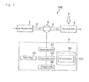
- a force calculation system comprises an air blowing unit 1, a flow passage 2, a flowmeter 3, a sensing unit 4, and a processing unit 5.
- the air blowing unit 1 is a device for blowing out air at a predetermined pressure.
- the air blowing unit 1 may be implemented by a combination of a compressor and a regulator valve.
- the flow passage 2 through which air flows from the air blowing unit 1 is connected to the air blowing unit 1.
- the flow passage 2 may be implemented by a plastic tube.
- leading end one end of the flow passage 2 on the side of the sensing unit 4
- base end the other end of the side of the air blowing unit 1
- the flowmeter 3 is a device for measuring the flow volume of air flowing through the flow passage.
- the flowmeter 3 may be implemented by a laminar flow type flowmeter, which comprises a laminar flow element and a sensor measuring a differential pressure between both ends.
- the sensing unit 4 is disposed at the end of the flow passage 2, and is deformed by the external force. The sensing unit 4 changes the ease of flow of air flowing through the flow passage 2 by deforming when the external force is applied to the sensing unit 4, to be discussed in detail below.
- the computing device 5 is a computer device comprising a receiving unit 51, a processing unit 52, a memory unit 53, an input unit 54, and an output unit 55.
- the receiving unit 51 is a device for receiving measurement data of the flow volume from the flowmeter 3.
- the computing device 5 may be implemented by an application specific integrated circuit.
- the processing unit 52 is a device for processing a variety of operations.
- the processing unit 52 may be implemented by a central processing unit (CPU).
- CPU central processing unit
- the processing unit 52 calculates the strength of external force applied to the sensing unit 4, to be discussed in detail below.
- the memory unit 53 is a device for storing information.
- the memory unit 53 may be implemented by a memory device such as a RAM (random access memory), a ROM (read only memory), or a HDD (hard disk drive) etc.
- the memory unit 53 stores the flow-volume - force correspondence relation information 531 between the external force applied to the sensing unit 4 and the flow volume of air which is blown out the air blowing unit and flows through the flow passage 2.
- the flow-volume - force correspondence relation information 531 denotes data information shown in graphs of Fig. 3(a) and (b) .
- the input unit 54 is a device for a user of computing device 5 to input information.
- the input unit 54 may be implemented by a keyboard or a mouse.
- the output unit 55 is a device for outputting information.
- the output unit 55 may be implemented by a device such as an external communication interface or a liquid crystal display (LCD) etc.
- LCD liquid crystal display
- the sensing unit 4 is explained.
- two types of sensing units may be explained.
- One is a tucked tube type, and the other is a slit type.
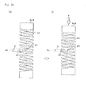
- Fig. 2A (a) shows the tucked tube type sensing unit 4a made of stainless steel, and the sensing unit 4a may be implemented using coil spring where the middle part of a cylindrical body is formed into a coiled shape.
- the aperture 41 of the sensing unit 4a tucks the middle portion 22 near the end portion 21.
- the flow passage 2 is elastically deformable tube.
- the sensing unit 4a has a diameter of 5 mm and an axial length of about 20 mm.
- Fig. 2A (b) shows an aperture 41 of which a width is changed when the external force is applied to the sensing unit 4 in an axial direction.
- the flow volume of air flowing through the flow passage 2 is changed, since an effective section area in the middle portion 22 is changed by a variation of the width of an aperture 41.
- the effective section area means section area in the direction vertical to air flow passing direction.
- the end portion 21 is pressured at the atmospheric pressure.
- Fig. 2B (a) shows the sensing unit 4b made of a cylindrical aluminum material.
- the sensing unit 4b has a slit 42 of which an opening width is changed when the external force is applied to the sensing unit 4 in an axial direction (a determined direction).
- a hole is bored in a part of a sidewall of the sensing unit 4b so that the end portion 21 of the flow passage 2 is put in the sensing unit 4b.
- the end portion 21 of the flow passage 2 is arranged at the slit 42.
- the flow passage 2 is made of an elastically deformable material.
- the sensing unit 4b has a diameter of 10 mm and an axial length of about 15 mm.
- a leading end 21 of the flow passage 2 and a facing plane 43 are placed from each other by a distance of d1, i.e., a width of a slit 42.
- Fig.2B (b) shows the flow passage 2 through which the flow volume of air is changed, since a distance between a leading end 21 of the flow passage 2 and a facing plane 43 is changed by a variation of a width of a slit 42, when the external force is applied to the sensing unit 4a (see Fig.2B (b1) ).
- Fig. 3 (a) shows results of the experiment on the tucked tube type sensing unit 4a.
- air pressure at the air blowing unit 1 is 400 kPaG, i.e., 400 kPa higher than 1 atmosphere
- the result shown by a curved line L1 is obtained.
- the coordinates show force F[N] in a horizontal axis and the flow volume [L/min(nor)] of air flowing through the flow passage 2 Q in a vertical axis.
- Fig. 3 (b) shows results of the experiment on the slit type sensing unit 4b.
- air pressure at the air blowing unit 1 is 50 kPaG
- the result shown by a curved line L2 is obtained.
- the coordinates show force F[N] in a horizontal axis and the flow volume [L/min(nor)] of air flowing through the flow passage 2 Q in a vertical axis.
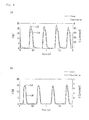
- Fig. 4 (a) shows results of the experiment on the tucked tube type sensing unit 4a.
- the results shown by curved lines L3 and L4 are obtained.
- the coordinates show a time in a horizontal axis and the force F and the flow volume of air flowing through the flow passage 2 Q in a vertical axis.
- Fig. 4 (b) shows results of the experiment on the slit type sensing unit 4b.
- the results shown by curved lines L5 and L6 are obtained.
- the coordinates show a time in a horizontal axis and the Force F and the flow volume of air flowing through the flow passage 2 Q in a vertical axis.
- computing device 5 processes operations using the force calculation system 100.
- the receiving unit 51 in the computing device 5 measures the flow volume of air flowing through the flow passage 2 (STEP S1).
- the receiving unit 51 receives measurement data of the flow volume of air flowing through the flow passage 2 from the flowmeter 3. Based on these measurement data, the processing unit 52 understands (measures) the flow volume of air flowing through the flow passage 2
- the processing unit 52 refers to the flow-volume - force correspondence relation information 531 stored in the memory unit 53 (STEP 3). Based on the flow-volume - force correspondence relation information 531 and the flow volume of air flowing through the flow passage 2 measured in STEP S1, the processing unit 52 calculates the strength of external force applied to the sensing unit 4.
- a processing unit 52 determines whether termination requirements are satisfied or not, wherein if this decision is "YES,” then the process terminates, and wherein if this decision is "NO,” then the process returns STEP S1.
- termination requirements may be requirements not only satisfied by manual operations such as input operations but also satisfied by auto operations in which it is executed when there is no external force applied to the sensing unit 4 during a predetermined time.
- the sensing unit 4 since the sensing unit 4 changes the ease of flow of air flowing through the flow passage 2 by deforming when the external force is applied to the sensing unit 4.
- the external force applied to the sensing unit 4 is calculated by the sensing unit 4 arranged in the end portion of the flow passage 2 and the flow-volume - force correspondence relation information 531 stored in a memory unit 53.
- a sensing unit 4 may be implemented by either a tucked tube type or a slit type.
- targeted detection is air volume, this is able to normally use under the electromagnetic environment such as the MRI device or explosion-proof environment such as a nuclear power plant.
- the sensing unit 4 has simple structure, it is possible to miniaturize it, to reduce parts count, and to achieve low cost and high durability.
- the air blowing unit 1 In addition, in the environment that there is a permanently-installed air pressure source (the air blowing unit 1) such as a hospital, it is possible to compactify the whole system using the air blowing unit 1.
- a sensing unit 4 is made of metal material such as stainless steel or aluminum.
- this invention is suitable for applying to a medical field.
- the system of this invention has high degrees of freedom of placement position, since the sensing unit 4 is connected to the flowmeter 3. More specifically, when using an optical fiber sensor, it is possible to disturb a movement of an articulated surgical robot due to rigidity of optical fibers with this robot.
- a tucked tube type sensing unit 4c tucks three flow passages 2a, 2b and 2c at different positions in the aperture 41.
- three flow passages 2a. 2b and 2c have flowmeters 3 respectively, and the flowmeters 3 measure the flow volumes of the flow passages 2a, 2b and 2c respectively.
- the flow passages 2d, 2e and 2f are arranged at deferent positions.
- three flow passages 2d, 2e and 2f have respectively flowmeters 3, and the flowmeters 3 measure the flow volumes of the flow passages 2d, 2e and 2f respectively.
- a sensing unit it is possible to calculate a direction and strength of force applied to one sensing unit, using a plurality of flow passages.
- material of the sensing unit 4 is not limited to the above embodiment.
- material of the sensing unit 4 is not limited to the above embodiment.
- another elastically deformable material such as titanium or plastic for the sensing unit 4.
- the sensing unit 4 is not limited to this structure.
- another elastic body which makes the width of the aperture change as a function of external force, such as a leaf spring or short spring.
- the shape of the sensing unit 4b is limited to a cylindrical shape.
- the sensing unit 4 is explained when it is applied to the force pushing it. However, it is possible to use a sensing unit 4 applied to the force pulling it. In this case, along with above information shown in Fig.3 (a) and (b) , it is necessary to obtain corresponding relationship between force and the flow volume under the condition that force is negative.
Landscapes
- Physics & Mathematics (AREA)
- General Physics & Mathematics (AREA)
- Fluid Mechanics (AREA)
- Measuring Volume Flow (AREA)
- Force Measurement Appropriate To Specific Purposes (AREA)
- Measurement Of The Respiration, Hearing Ability, Form, And Blood Characteristics Of Living Organisms (AREA)
Abstract
Description
- This invention relates to technology of a force calculation system, which is able to calculate the strength of force applied to a target area without an electrical device.
- Some of conventional methods of measuring force are widely used, for example, a strain gauge method using a variation of an electrical resistance (hereinafter electrical strain sensor), or a load cell method with a sensing unit equipped with a piezoelectric element. However, these methods cannot be used in strong electromagnetic environment such as a MRI (Magnetic Resonance Imaging) device, since these sensors must use electrical phenomena. In addition, there is a risk of a problem with the measurement accuracy decreasing due to interference with another electrical device.
- Thus, a light fiber type strain gauge (hereinafter, light fiber type sensor) has already put into practical use (see non-patent documents No.1 and 2). This technology has no problem to be caused by electrical phenomena as above, because it detects variations due to strain of a sensing unit, e.g., a wavelength, frequency, phase, and percolation of the light.
-
- Non-patent document No. 1: J. Peirs, et al., "A micro optical force sensor for force feedback during minimally invasive robotic surgery", Sensors and Actuators A 115 (2004), pp.447-455.
- Non-patent document No. 2: P. Polygerinos, et al., "A Fibre-Optic Catheter-Tip Force Sensor with MRI Compatibility: A Feasibility Study", 31st Annual International Conference of the IEEE EMBS Minneapolis, Minnesota, USA, September 2-6, 2009, pp.1501-1504.
- However, a light source with an optical switch and a signal conditioner for signal processing are required for the above light fiber type sensor. Therefore the whole system is more expensive and larger than the system of the electrical strain sensor.
- Thus, in view of the above-mentioned situation, problems to be solved by this invention is to provide an undersized and inexpensive force calculation system, which is able to calculate the strength of force applied to a target area without an electrical device.
- To solve the above problem, a force calculation system comprises an air blowing unit for blowing air at a predetermined pressure, a flow passage connected to the air blowing unit for blowing air, a sensing unit arranged in the end portion of the flow passage on the side opposite to the air blowing unit wherein the sensing unit makes ease of flow of air change as a function of deformation due to external force, a flowmeter measuring flow volume of air flowing through the flow passage, a memory unit for storing in advance information of correspondence relation between the strength of external force at the sensing unit and the flow volume of air flowing through the flow passage from the air blowing unit, and a processing unit for calculating the strength of the external force applied to the sensing unit based on the flow volume of air flowing through the flow passage as measured by the flowmeter and the information of the correspondence relation stored by the memory unit.
- According to the present invention, it is possible to provide an undersized and inexpensive force calculation system, which is able to calculate the strength of force applied to a target area without an electrical device.
-
-
Fig. 1 shows a schematic diagram of an embodiment of the force calculation system. -
Figs. 2A show a structure of the tucked tube type sensing unit.Fig. 2A(a) shows the structure before the external force is applied to the sensing unit.Fig. 2A(b) shows the structure after the external force has been applied to the sensing unit. -
Figs. 2B show a structure of the slit type sensing unit.Figs. 2B(a) and (a1) show the structure before the external force is applied to the sensing unit.Figs. 2B(b) and (b1) show the structure after the external force has been applied to the sensing unit. -
Figs. 3 show relationship between the external force applied to the sensing unit and the flow volume of air flowing through the flow passage.Fig. 3(a) shows a sample of the relationship using the tucked tube type sensing unit.Fig. 3(b) shows a sample of the relationship using the slit type sensing unit. -
Figs. 4 show dynamic characteristics between the external force applied to the sensing unit and the flow volume of air flowing through the flow passage.Fig. 4(a) shows a sample of the relationship using the tucked tube type sensing unit.Fig. 4(b) shows a sample of the relationship using the slit type sensing unit. -
Fig. 5 shows flowchart of processing flows in the processing unit of the computing device. -
Figs. 6 show structures of flow passages and the sensing unit in the case of having three flow passages.Fig. 6(a) shows a sample of the structure using the tucked tube type sensing unit.Fig. 6(b) shows a sample of the structure using the slit type sensing unit. - A force calculation system according to an embodiment of the present invention will be described in detail with reference to the drawings. In addition, for example, this embodiment assumes that a
force calculation system 100 is used when it is necessary to obtain the strength of force such as weft tension in suturing or elasticity from internal organs to a crow-bill due to using an endoscopic operation robot. - As shown in
Fig. 1 , a force calculation system comprises an air blowingunit 1, aflow passage 2, aflowmeter 3, asensing unit 4, and aprocessing unit 5. The air blowingunit 1 is a device for blowing out air at a predetermined pressure. For example, the air blowingunit 1 may be implemented by a combination of a compressor and a regulator valve. Theflow passage 2 through which air flows from the air blowingunit 1 is connected to the air blowingunit 1. For example, theflow passage 2 may be implemented by a plastic tube. - In addition, hereinafter one end of the
flow passage 2 on the side of thesensing unit 4 is called "leading end", the other end of the side of the air blowingunit 1 is called "base end." - The
flowmeter 3 is a device for measuring the flow volume of air flowing through the flow passage. For example, theflowmeter 3 may be implemented by a laminar flow type flowmeter, which comprises a laminar flow element and a sensor measuring a differential pressure between both ends. Thesensing unit 4 is disposed at the end of theflow passage 2, and is deformed by the external force. Thesensing unit 4 changes the ease of flow of air flowing through theflow passage 2 by deforming when the external force is applied to thesensing unit 4, to be discussed in detail below. - The
computing device 5 is a computer device comprising areceiving unit 51, aprocessing unit 52, amemory unit 53, aninput unit 54, and anoutput unit 55. Thereceiving unit 51 is a device for receiving measurement data of the flow volume from theflowmeter 3. For example, thecomputing device 5 may be implemented by an application specific integrated circuit. - The
processing unit 52 is a device for processing a variety of operations. For example, theprocessing unit 52 may be implemented by a central processing unit (CPU). Based on the measurement data of the flow volume of air flowing through theflow passage 2 and flow-volume - forcecorrespondence relation information 531 stored in thememory unit 53, theprocessing unit 52 calculates the strength of external force applied to thesensing unit 4, to be discussed in detail below. - The
memory unit 53 is a device for storing information. For example, thememory unit 53 may be implemented by a memory device such as a RAM (random access memory), a ROM (read only memory), or a HDD (hard disk drive) etc. Thememory unit 53 stores the flow-volume - forcecorrespondence relation information 531 between the external force applied to thesensing unit 4 and the flow volume of air which is blown out the air blowing unit and flows through theflow passage 2. - More specifically, the flow-volume - force
correspondence relation information 531 denotes data information shown in graphs ofFig. 3(a) and (b) . - The
input unit 54 is a device for a user ofcomputing device 5 to input information. For example, theinput unit 54 may be implemented by a keyboard or a mouse. - The
output unit 55 is a device for outputting information. For example, theoutput unit 55 may be implemented by a device such as an external communication interface or a liquid crystal display (LCD) etc. - Next, the
sensing unit 4 is explained. In this embodiment, for example, two types of sensing units may be explained. One is a tucked tube type, and the other is a slit type. - Firstly, the tucked tube
type sensing unit 4a is explained. -
Fig. 2A (a) shows the tucked tubetype sensing unit 4a made of stainless steel, and thesensing unit 4a may be implemented using coil spring where the middle part of a cylindrical body is formed into a coiled shape. Theaperture 41 of thesensing unit 4a tucks themiddle portion 22 near theend portion 21. - In addition, it is necessary that the
flow passage 2 is elastically deformable tube. Furthermore, for example, thesensing unit 4a has a diameter of 5 mm and an axial length of about 20 mm. -
Fig. 2A (b) shows anaperture 41 of which a width is changed when the external force is applied to thesensing unit 4 in an axial direction. Thus the flow volume of air flowing through theflow passage 2 is changed, since an effective section area in themiddle portion 22 is changed by a variation of the width of anaperture 41. Here the effective section area means section area in the direction vertical to air flow passing direction. In addition, theend portion 21 is pressured at the atmospheric pressure. - Secondly, the tucked tube
type sensing unit 4b is explained. -
Fig. 2B (a) shows thesensing unit 4b made of a cylindrical aluminum material. Thesensing unit 4b has aslit 42 of which an opening width is changed when the external force is applied to thesensing unit 4 in an axial direction (a determined direction). In addition, a hole is bored in a part of a sidewall of thesensing unit 4b so that theend portion 21 of theflow passage 2 is put in thesensing unit 4b. Thus theend portion 21 of theflow passage 2 is arranged at theslit 42. - In addition, it is not necessary that the
flow passage 2 is made of an elastically deformable material. Furthermore, for example, thesensing unit 4b has a diameter of 10 mm and an axial length of about 15 mm. - In this case, as shown in
Fig. 2B (a1) , a leadingend 21 of theflow passage 2 and a facingplane 43 are placed from each other by a distance of d1, i.e., a width of aslit 42. -
Fig.2B (b) shows theflow passage 2 through which the flow volume of air is changed, since a distance between aleading end 21 of theflow passage 2 and a facingplane 43 is changed by a variation of a width of aslit 42, when the external force is applied to thesensing unit 4a (seeFig.2B (b1) ). - In addition, the longer distance between a
leading end 21 of theflow passage 2 and a facingplane 43 there is, the more flow volume increases. - Next, experimental results regarding correspondence relation between eternal force and the flow volume are explained.
-
Fig. 3 (a) shows results of the experiment on the tucked tubetype sensing unit 4a. When air pressure at theair blowing unit 1 is 400 kPaG, i.e., 400 kPa higher than 1 atmosphere, the result shown by a curved line L1 is obtained. InFig. 3 (a) , the coordinates show force F[N] in a horizontal axis and the flow volume [L/min(nor)] of air flowing through the flow passage 2 Q in a vertical axis. - In view of this experiment, the significant change of the flow volume of air flowing through the
flow passage 2 is obtained, if the external force is applied to thesensing unit 4a. -
Fig. 3 (b) shows results of the experiment on the slittype sensing unit 4b. When air pressure at theair blowing unit 1 is 50 kPaG, the result shown by a curved line L2 is obtained. Here the coordinates show force F[N] in a horizontal axis and the flow volume [L/min(nor)] of air flowing through the flow passage 2 Q in a vertical axis. - In view of this experiment, the significant change of the flow volume of air flowing through the
flow passage 2 is obtained, if the external force is applied to thesensing unit 4b. - Next, experimental results regarding dynamic characteristics, i.e., temporal response performance of the flow volume variation to the external force are explained.
-
Fig. 4 (a) shows results of the experiment on the tucked tubetype sensing unit 4a. When the external force of about 20-25 N is several times applied to thesensing unit 4a by hands, the results shown by curved lines L3 and L4 are obtained. InFig. 4 (a) , the coordinates show a time in a horizontal axis and the force F and the flow volume of air flowing through the flow passage 2 Q in a vertical axis. - In view of this experiment, the temporal change in the flow volume of air flowing through the
flow passage 2 follows the temporal change of the external force applied to thesensing unit 4a. -
Fig. 4 (b) shows results of the experiment on the slittype sensing unit 4b. When the external force of about 15-20 N is several times applied to thesensing unit 4a by hands, the results shown by curved lines L5 and L6 are obtained. InFig. 4 (b) , the coordinates show a time in a horizontal axis and the Force F and the flow volume of air flowing through the flow passage 2 Q in a vertical axis. - In view of this experiment, the temporal change in the flow volume of air flowing through the
flow passage 2 follows the temporal change of the external force applied to thesensing unit 4b. - To evaluate dynamic characteristics of the
sensing units - Next, it is explained how
computing device 5 processes operations using theforce calculation system 100. - Firstly, the receiving
unit 51 in thecomputing device 5 measures the flow volume of air flowing through the flow passage 2 (STEP S1). - More specifically, the receiving
unit 51 receives measurement data of the flow volume of air flowing through theflow passage 2 from theflowmeter 3. Based on these measurement data, theprocessing unit 52 understands (measures) the flow volume of air flowing through theflow passage 2 - Secondly, the
processing unit 52 refers to the flow-volume - forcecorrespondence relation information 531 stored in the memory unit 53 (STEP 3). Based on the flow-volume - forcecorrespondence relation information 531 and the flow volume of air flowing through theflow passage 2 measured in STEP S1, theprocessing unit 52 calculates the strength of external force applied to thesensing unit 4. - In addition, when the
force calculation system 100 is applied to a surgical robot, for example, feedback control in which a remote-operating medical doctor automatically obtains the force calculated by the STEP S3 may be executed. - Next, a
processing unit 52 determines whether termination requirements are satisfied or not, wherein if this decision is "YES," then the process terminates, and wherein if this decision is "NO," then the process returns STEP S1. - In addition, termination requirements may be requirements not only satisfied by manual operations such as input operations but also satisfied by auto operations in which it is executed when there is no external force applied to the
sensing unit 4 during a predetermined time. - According to the above embodiment for the
force calculation system 100, since thesensing unit 4 changes the ease of flow of air flowing through theflow passage 2 by deforming when the external force is applied to thesensing unit 4. The external force applied to thesensing unit 4 is calculated by thesensing unit 4 arranged in the end portion of theflow passage 2 and the flow-volume - forcecorrespondence relation information 531 stored in amemory unit 53. - Thus, it is possible to provide an undersized and inexpensive force calculation system, which calculates strength of force applied to a target area without an electrical device.
- More specifically, a
sensing unit 4 may be implemented by either a tucked tube type or a slit type. - In addition, as targeted detection is air volume, this is able to normally use under the electromagnetic environment such as the MRI device or explosion-proof environment such as a nuclear power plant.
- Furthermore, as the
sensing unit 4 has simple structure, it is possible to miniaturize it, to reduce parts count, and to achieve low cost and high durability. - To apply a surgical robot, as the end of a forceps has a diameter size of about 10 mm, it is possible to provide the sensing unit with the forceps.
- In addition, in the environment that there is a permanently-installed air pressure source (the air blowing unit 1) such as a hospital, it is possible to compactify the whole system using the
air blowing unit 1. - Furthermore it is possible to withstand high temperature sterilization treatment in about 125 °C, since a
sensing unit 4 is made of metal material such as stainless steel or aluminum. Thus this invention is suitable for applying to a medical field. - In addition, the system of this invention has high degrees of freedom of placement position, since the
sensing unit 4 is connected to theflowmeter 3. More specifically, when using an optical fiber sensor, it is possible to disturb a movement of an articulated surgical robot due to rigidity of optical fibers with this robot. - On the other hand, in this embodiment, it is possible to use a low rigidity material for
flow passage 2, thus it is possible to avoid this problem. - Next, another variation of a
sensing unit 4 is explained. - As shown in
Fig.6 (a) , a tucked tube type sensing unit 4c tucks threeflow passages aperture 41. In this case, for example, threeflow passages 2a. 2b and 2c haveflowmeters 3 respectively, and theflowmeters 3 measure the flow volumes of theflow passages - In this case, it is possible to calculate respectively the strength of external force based on the flow-volume - force
correspondence relation information 531 stored inmemory unit 53 and the flow volumes of air flowing through theflow passages 2aprocessing unit 52, it is possible to calculate the direction and the strength of external force applied to the sensing unit 4c based on this information. In addition, the system is able to have each flow-volume and force correspondence relation information corresponding to each offlow passages - In addition, as shown in
Fig.6 (b) , in a slittype sensing unit 4d, theflow passages flow passages flowmeters 3, and theflowmeters 3 measure the flow volumes of theflow passages - In this case, it is possible to calculate respectively the strength of external force, based on the flow-volume - force
correspondence relation information 531 stored inmemory unit 53 and flow volumes of air flowing through theflow passages 2dprocessing unit 52, it is possible to calculate the direction and the strength of external force applied to the sensing unit 4c based on this information. In addition, the system is able to have each flow-volume and force correspondence relation information corresponding to each offlow passages - As mentioned above, according to another variation of a sensing unit, it is possible to calculate a direction and strength of force applied to one sensing unit, using a plurality of flow passages.
- This invention is not limited to above embodiment. For example, material of the
sensing unit 4 is not limited to the above embodiment. For example, it is possible to use another elastically deformable material such as titanium or plastic for thesensing unit 4. - In addition, as a sample of a coil spring is explained regarding the tucked tube
type sensing unit 4, thesensing unit 4 is not limited to this structure. For example, it is possible to use another elastic body, which makes the width of the aperture change as a function of external force, such as a leaf spring or short spring. - In addition, as a sample of a computer is explained regarding the
computing device 5, it is possible to use a LSI or an IC integrated the receivingunit 51, the receivingunit 52 and theprocessing unit 53 etc. - In addition, the shape of the
sensing unit 4b is limited to a cylindrical shape. For example, it is possible to use another shape such as polygonal shape for the shape of thesensing unit 4b. - Furthermore it is possible to have two slit in the
helical slit 42 and to close the opening in the bottom of thesensing unit 4b. - In addition, in this embodiment, the
sensing unit 4 is explained when it is applied to the force pushing it. However, it is possible to use asensing unit 4 applied to the force pulling it. In this case, along with above information shown inFig.3 (a) and (b) , it is necessary to obtain corresponding relationship between force and the flow volume under the condition that force is negative. - Regarding structures such as hardware or flowchart, it is possible to modify structures appropriately, if the scope of the present invention is not changed.
-
- 1
- air blowing unit
- 2
- flow passage
- 3
- flowmeter
- 4
- sensing unit
- 5
- computing device
- 21
- end portion
- 22
- middle portion
- 41
- aperture
- 42
- slit
- 43
- facing plane
- 51
- receiving unit
- 52
- processing unit
- 53
- memory unit
- 54
- input unit
- 55
- output unit
- 100
- force calculation system
- 531
- flow-volume - force correspondence relation information (in figures, abbreviated to "FF information")
Claims (4)
- A force calculation system comprising:an air blowing unit for blowing air at a predetermined pressure,a flow passage connected to the air blowing unit for blowing air,a sensing unit arranged in the end portion of the flow passage on the side opposite to the air blowing unit wherein the ease of flow of air is changed by deformation due to external force,a flowmeter measuring flow volume of air flowing through the flow passage,a memory unit for storing in advance information of correspondence relation between the strength of external force at the sensing unit and the flow volume of air flowing through the flow passage from the air blowing unit, anda processing unit for calculating the strength of the external force applied to the sensing unit based on the flow volume of air flowing through the flow passage as measured by the flowmeter and the information of the correspondence relation stored by the memory unit.
- A force calculation system according to claims 1,
wherein the sensing unit comprises a aperture tucking the flow passage down,
the aperture is made of an elastic body wherein a width of the aperture is changed by the external force,
the flow passage is made of elastically deformable tube, and the aperture made of the elastic body tucks down the end portion of the flow passage on the side opposite to the air blowing unit, and
the flow volume of air flowing the tube is changed by a variation of the width of the aperture due to the external force applied to the elastic body. - A force calculation system according to claims 1,
wherein the sensing unit comprises a slit of which a slit width changes as a function of the external force in a predetermined direction at the sensing unit,
the flow passage is made of a tube, and the end portion of the flow passage on the side opposite to the air blowing unit is positioned at the slit, and
if the external force in the predetermined direction is applied to the sensing unit, the external force at the sensing unit makes the flow volume of air flowing through the tube change as a function of a variation of the slit width due to changing a distance between the end portion and its facing plane. - A force calculation system according to any one claims 1 to 3, further comprising a plurality of flow passages, and a plurality of flowmeters,
wherein one end of each of flow passages is directly or indirectly connected to the air blowing unit,
the other end of each of passages is arranged at a different position in the sensing unit from each other,
each of flow passages has each flowmeters, and
the processing unit calculating respectively the strength of the external force at the other end of each passage, based on each flow volume of air flowing through each of a plurality of the flow passages and the information of the correspondence relation stored by the memory unit.
Applications Claiming Priority (2)
| Application Number | Priority Date | Filing Date | Title |
|---|---|---|---|
| JP2011098178A JP5704712B2 (en) | 2011-04-26 | 2011-04-26 | Force calculation system |
| PCT/JP2012/060731 WO2012147655A1 (en) | 2011-04-26 | 2012-04-20 | Force calculation system |
Publications (2)
| Publication Number | Publication Date |
|---|---|
| EP2703796A1 true EP2703796A1 (en) | 2014-03-05 |
| EP2703796A4 EP2703796A4 (en) | 2015-01-21 |
Family
ID=47072175
Family Applications (1)
| Application Number | Title | Priority Date | Filing Date |
|---|---|---|---|
| EP12777692.0A Withdrawn EP2703796A4 (en) | 2011-04-26 | 2012-04-20 | FORCE CALCULATION SYSTEM |
Country Status (4)
| Country | Link |
|---|---|
| US (1) | US9091605B2 (en) |
| EP (1) | EP2703796A4 (en) |
| JP (1) | JP5704712B2 (en) |
| WO (1) | WO2012147655A1 (en) |
Cited By (2)
| Publication number | Priority date | Publication date | Assignee | Title |
|---|---|---|---|---|
| CN108120739A (en) * | 2018-01-24 | 2018-06-05 | 西安理工大学 | A kind of thermal deformation measurement device for high-precision machine tool hydrostatic bearing |
| US11221265B2 (en) | 2018-04-20 | 2022-01-11 | Mie Robot Exterior Technology Laboratory Co., Ltd. | Contact detecting device |
Families Citing this family (2)
| Publication number | Priority date | Publication date | Assignee | Title |
|---|---|---|---|---|
| JP5971638B1 (en) * | 2016-05-12 | 2016-08-17 | 株式会社三重木型製作所 | Contact detection device |
| CN108972601B (en) * | 2018-08-10 | 2024-03-26 | 佛山科学技术学院 | End effector capable of sensing three-dimensional force |
Family Cites Families (13)
| Publication number | Priority date | Publication date | Assignee | Title |
|---|---|---|---|---|
| JPS4947770A (en) * | 1972-07-14 | 1974-05-09 | ||
| JPS55106329A (en) * | 1979-02-09 | 1980-08-15 | Mitsubishi Heavy Ind Ltd | Load detector |
| JPS6056208U (en) * | 1983-09-27 | 1985-04-19 | 株式会社東芝 | air micrometer |
| JPS617431A (en) * | 1984-06-21 | 1986-01-14 | Marui Seisakusho:Kk | Annular spring type force gage |
| FR2681135A1 (en) * | 1991-09-05 | 1993-03-12 | Diot Gael | Method for measuring the flow rate of a fluid in a pipe. Flow meter employing this method. As a corollary: meter |
| JPH09500968A (en) * | 1993-08-19 | 1997-01-28 | ヴェンチュアダイン リミテッド | Particle sensor with low pressure drop airflow system |
| US6253625B1 (en) * | 2000-10-13 | 2001-07-03 | Predator Systems, Inc. | Target flow meters with immersed strain gauges |
| US7438073B2 (en) * | 2002-03-08 | 2008-10-21 | Kaerys S.A. | Air assistance apparatus for computing the airflow provided by only means of pressure sensors |
| JP3986050B2 (en) | 2002-03-28 | 2007-10-03 | 国立大学法人 奈良先端科学技術大学院大学 | Force detection device |
| US6701778B2 (en) * | 2002-04-25 | 2004-03-09 | John A. Taylor | Coating stretch tester |
| US6994620B2 (en) * | 2003-04-30 | 2006-02-07 | Carrier Corporation | Method of determining static pressure in a ducted air delivery system using a variable speed blower motor |
| JP5203798B2 (en) * | 2008-05-14 | 2013-06-05 | 日本電産シンポ株式会社 | Air micrometer |
| DE102011107547B4 (en) * | 2011-07-11 | 2015-08-06 | Krohne Messtechnik Gmbh | Pressure transducer for a vortex flowmeter, vortex flowmeter and method of making such a pressure transducer |
-
2011
- 2011-04-26 JP JP2011098178A patent/JP5704712B2/en not_active Expired - Fee Related
-
2012
- 2012-04-20 WO PCT/JP2012/060731 patent/WO2012147655A1/en not_active Ceased
- 2012-04-20 US US14/114,071 patent/US9091605B2/en not_active Expired - Fee Related
- 2012-04-20 EP EP12777692.0A patent/EP2703796A4/en not_active Withdrawn
Cited By (2)
| Publication number | Priority date | Publication date | Assignee | Title |
|---|---|---|---|---|
| CN108120739A (en) * | 2018-01-24 | 2018-06-05 | 西安理工大学 | A kind of thermal deformation measurement device for high-precision machine tool hydrostatic bearing |
| US11221265B2 (en) | 2018-04-20 | 2022-01-11 | Mie Robot Exterior Technology Laboratory Co., Ltd. | Contact detecting device |
Also Published As
| Publication number | Publication date |
|---|---|
| JP5704712B2 (en) | 2015-04-22 |
| US9091605B2 (en) | 2015-07-28 |
| WO2012147655A1 (en) | 2012-11-01 |
| US20140047929A1 (en) | 2014-02-20 |
| JP2012229980A (en) | 2012-11-22 |
| EP2703796A4 (en) | 2015-01-21 |
Similar Documents
| Publication | Publication Date | Title |
|---|---|---|
| Galloway et al. | Fiber optic shape sensing for soft robotics | |
| US20240350209A1 (en) | Method and system for operating a surgical instrument | |
| Bandari et al. | Miniaturized optical force sensor for minimally invasive surgery with learning-based nonlinear calibration | |
| US9091605B2 (en) | Force calculating system | |
| York et al. | A wrist for needle-sized surgical robots | |
| AU2010241467B2 (en) | Calibration system for a pressure-sensitive catheter | |
| US8312779B2 (en) | Force sensor for the detection of a force vector | |
| US12569145B2 (en) | System and method for determining body core temperature | |
| CN104764552B (en) | A kind of force-sensing sensor perceived for operation technique power | |
| JP4767175B2 (en) | Trocar device for passing surgical instruments | |
| US20200093548A1 (en) | Fiber management in medical instrument backend | |
| He et al. | Development of a miniaturized 3-DOF force sensing instrument for robotically assisted retinal microsurgery and preliminary results | |
| US20080139916A1 (en) | Determining the length of a long, flexible instrument | |
| Xie et al. | Design of an FBG-based tension sensor with high sensitivity and linearity for cable-driven continuum robots | |
| US20140235999A1 (en) | Method for determining the shape of a surgical instrument and surgical instrument having a deformable body | |
| Ahmadi et al. | High sensitive force sensing based on the optical fiber coupling loss | |
| US10292775B2 (en) | Systems and method for determining the shape of a surgical instrument and surgical instruments having a deformable body | |
| US20240000417A1 (en) | Cranial implants with integrated ultrasound-based pressure sensing | |
| Beckers et al. | A Quasi-Static Model Accounting for Friction-Induced Hysteresis in Tendon-Actuated Superelastic Notched Tube Instruments | |
| Liu et al. | Miniature fiber-optic force sensor for vitreoretinal microsurgery based on low-coherence Fabry-Pérot interferometry | |
| Ahmadi et al. | A new MRI-compatible optical fiber tactile sensor for use in minimally invasive robotic surgery systems | |
| Wurdemann et al. | Integrated soft bending sensor for soft robotic manipulators | |
| CN119587140A (en) | Dual-parameter sensor and balloon catheter contact direction and contact force evaluation device and evaluation method | |
| Mardasi et al. | Design and finite element modeling of a novel optical microsystems-based tactile sensor for minimal invasive robotic surgery | |
| Miguel et al. | Implantable MEMS Pressure Sensors Modelling Tool |
Legal Events
| Date | Code | Title | Description |
|---|---|---|---|
| PUAI | Public reference made under article 153(3) epc to a published international application that has entered the european phase |
Free format text: ORIGINAL CODE: 0009012 |
|
| 17P | Request for examination filed |
Effective date: 20131116 |
|
| AK | Designated contracting states |
Kind code of ref document: A1 Designated state(s): AL AT BE BG CH CY CZ DE DK EE ES FI FR GB GR HR HU IE IS IT LI LT LU LV MC MK MT NL NO PL PT RO RS SE SI SK SM TR |
|
| DAX | Request for extension of the european patent (deleted) | ||
| A4 | Supplementary search report drawn up and despatched |
Effective date: 20141218 |
|
| RIC1 | Information provided on ipc code assigned before grant |
Ipc: G01L 1/00 20060101ALI20141212BHEP Ipc: G01F 1/20 20060101ALI20141212BHEP Ipc: G01F 1/28 20060101ALI20141212BHEP Ipc: G01L 1/04 20060101AFI20141212BHEP Ipc: G01L 1/02 20060101ALI20141212BHEP |
|
| STAA | Information on the status of an ep patent application or granted ep patent |
Free format text: STATUS: THE APPLICATION HAS BEEN WITHDRAWN |
|
| 18W | Application withdrawn |
Effective date: 20160323 |