EP2703770A1 - Dynamic quantity measuring apparatus - Google Patents
Dynamic quantity measuring apparatus Download PDFInfo
- Publication number
- EP2703770A1 EP2703770A1 EP11864095.2A EP11864095A EP2703770A1 EP 2703770 A1 EP2703770 A1 EP 2703770A1 EP 11864095 A EP11864095 A EP 11864095A EP 2703770 A1 EP2703770 A1 EP 2703770A1
- Authority
- EP
- European Patent Office
- Prior art keywords
- cutout
- sensor chip
- arm portion
- mechanical quantity
- measuring device
- Prior art date
- Legal status (The legal status is an assumption and is not a legal conclusion. Google has not performed a legal analysis and makes no representation as to the accuracy of the status listed.)
- Withdrawn
Links
- 239000000463 material Substances 0.000 claims description 12
- 230000008859 change Effects 0.000 abstract description 20
- 239000000853 adhesive Substances 0.000 description 25
- 230000001070 adhesive effect Effects 0.000 description 25
- 239000004065 semiconductor Substances 0.000 description 7
- 230000000694 effects Effects 0.000 description 6
- 239000011347 resin Substances 0.000 description 6
- 229920005989 resin Polymers 0.000 description 6
- 239000000758 substrate Substances 0.000 description 6
- 239000012535 impurity Substances 0.000 description 5
- 239000013078 crystal Substances 0.000 description 3
- 239000003822 epoxy resin Substances 0.000 description 3
- 229920000647 polyepoxide Polymers 0.000 description 3
- 238000004519 manufacturing process Methods 0.000 description 2
- 230000000452 restraining effect Effects 0.000 description 2
- 230000035945 sensitivity Effects 0.000 description 2
- 238000012360 testing method Methods 0.000 description 2
- XUIMIQQOPSSXEZ-UHFFFAOYSA-N Silicon Chemical compound [Si] XUIMIQQOPSSXEZ-UHFFFAOYSA-N 0.000 description 1
- 230000009471 action Effects 0.000 description 1
- 230000015572 biosynthetic process Effects 0.000 description 1
- 230000007423 decrease Effects 0.000 description 1
- 230000001419 dependent effect Effects 0.000 description 1
- 230000014509 gene expression Effects 0.000 description 1
- PCHJSUWPFVWCPO-UHFFFAOYSA-N gold Chemical compound [Au] PCHJSUWPFVWCPO-UHFFFAOYSA-N 0.000 description 1
- 239000010931 gold Substances 0.000 description 1
- 229910052737 gold Inorganic materials 0.000 description 1
- 238000005259 measurement Methods 0.000 description 1
- 239000002184 metal Substances 0.000 description 1
- 229910052751 metal Inorganic materials 0.000 description 1
- 230000004048 modification Effects 0.000 description 1
- 238000012986 modification Methods 0.000 description 1
- 229920001721 polyimide Polymers 0.000 description 1
- 239000009719 polyimide resin Substances 0.000 description 1
- 238000004080 punching Methods 0.000 description 1
- 230000009467 reduction Effects 0.000 description 1
- 230000003014 reinforcing effect Effects 0.000 description 1
- 230000003252 repetitive effect Effects 0.000 description 1
- 230000004044 response Effects 0.000 description 1
- 229910052710 silicon Inorganic materials 0.000 description 1
- 239000010703 silicon Substances 0.000 description 1
Images





Classifications
-
- G—PHYSICS
- G01—MEASURING; TESTING
- G01B—MEASURING LENGTH, THICKNESS OR SIMILAR LINEAR DIMENSIONS; MEASURING ANGLES; MEASURING AREAS; MEASURING IRREGULARITIES OF SURFACES OR CONTOURS
- G01B7/00—Measuring arrangements characterised by the use of electric or magnetic techniques
- G01B7/16—Measuring arrangements characterised by the use of electric or magnetic techniques for measuring the deformation in a solid, e.g. by resistance strain gauge
-
- G—PHYSICS
- G01—MEASURING; TESTING
- G01L—MEASURING FORCE, STRESS, TORQUE, WORK, MECHANICAL POWER, MECHANICAL EFFICIENCY, OR FLUID PRESSURE
- G01L1/00—Measuring force or stress, in general
- G01L1/18—Measuring force or stress, in general using properties of piezo-resistive materials, i.e. materials of which the ohmic resistance varies according to changes in magnitude or direction of force applied to the material
-
- G—PHYSICS
- G01—MEASURING; TESTING
- G01L—MEASURING FORCE, STRESS, TORQUE, WORK, MECHANICAL POWER, MECHANICAL EFFICIENCY, OR FLUID PRESSURE
- G01L1/00—Measuring force or stress, in general
- G01L1/26—Auxiliary measures taken, or devices used, in connection with the measurement of force, e.g. for preventing influence of transverse components of force, for preventing overload
-
- H—ELECTRICITY
- H10—SEMICONDUCTOR DEVICES; ELECTRIC SOLID-STATE DEVICES NOT OTHERWISE PROVIDED FOR
- H10D—INORGANIC ELECTRIC SEMICONDUCTOR DEVICES
- H10D48/00—Individual devices not covered by groups H10D1/00 - H10D44/00
- H10D48/50—Devices controlled by mechanical forces, e.g. pressure
-
- G—PHYSICS
- G01—MEASURING; TESTING
- G01L—MEASURING FORCE, STRESS, TORQUE, WORK, MECHANICAL POWER, MECHANICAL EFFICIENCY, OR FLUID PRESSURE
- G01L19/00—Details of, or accessories for, apparatus for measuring steady or quasi-steady pressure of a fluent medium insofar as such details or accessories are not special to particular types of pressure gauges
- G01L19/14—Housings
- G01L19/147—Details about the mounting of the sensor to support or covering means
Definitions
- the present invention relates to a mechanical quantity measuring device in which a sensor chip is supported on a flexible wiring board.
- a mechanical quantity measuring device can be attached to an object to be measured and thus can measure a mechanical quantity acting on the object to be measured.
- a device which uses a sensor chip applying an effect of resistance that varies depending on the strain (piezoresistive effect) is proposed.
- An impurity diffused resistor is formed on a surface of this sensor chip and the sensor chip is attached to an object to be measured, with an adhesive.
- the impurity diffused resistor is strained via the adhesive and the resistance thereof changes. Therefore, this change in resistance can be outputted as a sense output and the mechanical quantity (strain) acting on the object to be measured can be detected.
- the sense output may change with time in some cases.
- an object of the invention is to provide a mechanical quantity measuring device capable of restraining change in sense output with time.
- a mechanical quantity measuring device includes a sensor chip which outputs a sense output corresponding to a mechanical quantity acting on the object to be measured, and a flexible wiring board which supports the sensor chip and has a wire to lead out the sense output to outside, and in measuring the mechanical quantity, the sensor chip and the flexible wiring board are attached to the object to be measured.
- the mechanical quantity measuring device is characterized in that a cutout is provided on the flexible wiring board near the sensor chip and on the side where the wire is arranged for the sensor chip.
- a mechanical quantity measuring device capable of restraining change in sense output with time can be provided.
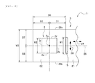
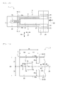
- FIG. 1A shows a plan view of a mechanical quantity measuring device 1 according to a first embodiment of the invention.
- the mechanical quantity measuring device 1 has a sensor chip 2 and a flexible wiring board 3 supporting the sensor chip 2.
- the sensor chip 2 can output a sense output S corresponding to a mechanical quantity acting on an object to be measured 4 (see FIG. 3 ).
- the flexible wiring board 3 has a wire 6 and an external electrode 25 electrically connected to the wire 6.
- the wire 6 is electrically connected to the sensor chip 2 and leas out a sense output S from the sensor chip 2.
- the external electrode 25 outputs the sense output S from the wire 6 to outside.
- the flexible wiring board 3 has an arm portion 21 and a base portion 24 connected to the arm portion 21.
- the arm portion 21 supports the sensor chip 2 at a distal end part 22 thereof and is connected to the base portion 24 at a root part 23 thereof.
- the wire 6 is laid from the distal end part 22 to the root part 23 of the arm portion 21.
- the external electrode 25 connected to the wire 6 is provided in the base portion 24, the external electrode 25 connected to the wire 6 is provided.
- the flexible wiring board 3 is used in a number of semiconductor packaged products, utilizing its excellent flexibility. Also, the flexible wiring board can be reduced in thickness to 100 ⁇ m or below and enables reduction in size of the wiring portion and therefore is an essential component of a portable electronic device.
- the flexible wiring board 3 is provided with a cutout (slit) 5.
- the cutout (slit) 5 is provided in the flexible wiring board 3 between the sensor chip 2 and the external electrode 25.
- the cutout (slit) 5 is provided in the flexible wiring board 3 near the sensor chip 2 and on the side where the wire 6 is arranged for the sensor chip 2.
- the cutout 5 is provided on the side of the external electrode 25 with respect to the sensor chip 2, in a longitudinal direction 27 of the arm portion 21 that is a direction from the distal end part 22 toward the root part 23 of the arm portion 21.
- a longitudinal direction 28 of the cutout 5 intersects the longitudinal direction 27 of the arm portion 21 substantially at right angles.
- the longitudinal direction 28 of the cutout 5 intersects, substantially at right angles, a center line 26 of the arm portion 21 that is parallel to the longitudinal direction 27 of the arm portion 21. Meanwhile, the cutout 5 can be produced by punching with a metal press mold, similarly to the formation of the outer shape of the flexible wiring board 3, and therefore is not a factor that increases cost.
- the sensor chip 2 is arranged in such a way that a center point 2a thereof is situated on the center line 26 of the arm portion 21. Also, the sensor chip 2 is arranged with line symmetry about the center line 26 of the arm portion 21.
- the wire 6 plural wires (in the example of FIG. 1A , four wires) are laid.
- the plural wires 6 are drawn to detour around the cutout 5.
- the plural wires 6 are arranged with line symmetry to each other about the center line 26 of the arm portion 21.
- a base film 17 is exposed almost across the entire surface.
- FIG. 1B shows a bottom view of the mechanical quantity measuring device 1 according to the first embodiment of the invention.
- the sensor chip 2 is supported on the back side of the flexible wiring board 3.
- the wires 6 are formed below the base film 17 and are also covered with an insulating film 16. That is, the wires 6 are covered with the base film 17 from the face side of the flexible wiring board 3 and are covered with the insulating film 16 from the back side of the flexible wiring board 3.
- the external electrode 25 is formed below the base film 17. The lower side of the external electrode 25 is exposed, instead of being covered with the insulating film 16, and is connectable to an external device.
- FIG. 2 shows an enlarged view around the sensor chip 2 in the mechanical quantity measuring device 1 according to the first embodiment of the invention.
- Both ends in the longitudinal direction 28 of the cutout 5 are arcuate.
- the cutout 5 is line-symmetrical about the center line 26 parallel to the longitudinal direction 27 of the arm portion 21.
- a width W1 of the cutout 5 in the direction intersecting the longitudinal direction 27 of the arm portion 21 substantially at right angles is bisected by the center line 26 of the arm portion 21.
- the width W1 of the cutout 5 in the direction intersecting the longitudinal direction 27 of the arm portion 21 substantially at right angles is substantially equal to or greater than a width W2 of the sensor chip 2 in the direction intersecting the longitudinal direction 27 of the arm portion 21 substantially at right angles (W1 ⁇ W2).
- the center point 2a of the sensor chip 2 is arranged on the center line 26 parallel to the longitudinal direction 27 of the arm portion 21.
- the sensor chip 2 is substantially square, as viewed in a plan view.
- a side 2b is arranged facing the cutout 5.
- a side 2c is arranged parallel to and facing the end side on the distal end part 22 of the arm portion 21.
- a side 2d is arranged parallel to and facing the lateral side 29a of the flexible wiring board 3 along the longitudinal direction 27 of the arm portion 21.
- a side 2e is arranged parallel to and facing the lateral side 29b of the flexible wiring board 3 along the longitudinal direction 27 of the arm portion 21.
- the side 2b of the sensor chip 2 that faces the cutout 5 intersects the center line 26 of the arm portion 21 substantially at right angles.
- the longitudinal direction 28 of the cutout 5 intersects the longitudinal direction 27 (center line 26) of the arm portion 21 substantially at right angles. Then, the longitudinal direction 28 of the cutout 5 is arranged parallel to the side 2b.
- the distance D1 from the cutout 5 to the center point 2a of the sensor chip 2 is substantially equal to half the width W3 of the arm portion 21 in the direction intersecting the longitudinal direction 27 of the arm portion 21 substantially at right angles at the center point 2a of the sensor chip 2.
- the sensor chip 2 that is square as viewed in a plan view
- its shape is not limited to this and may be, for example, rectangular or circle as long as the center point 2a can be decided.
- FIG. 3 shows the state where the mechanical quantity measuring device 1 according to the first embodiment of the invention is attached to an object to be measured 4 with an adhesive 7.
- the mechanical quantity measuring device 1 when measuring a mechanical quantity, the sensor chip 2 and the flexible wiring board 3 are attached to the object to be measured 4 with the adhesive 7.
- the adhesive 7 is applied not only to the distal end part 22 of the arm portion 21 around the sensor chip 2 but also to an area from the distal end part 22 of the arm portion 21 to the vicinity of the root part 23.
- An adhesive end surface 7c of the adhesive 7 reaches the vicinity of the root part 23 of the arm portion 21.
- the adhesive 7 is not applied to the base portion 24 of the flexible wiring board 3.
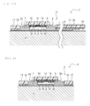
- FIG. 4 shows an enlarged view of essential parts of a sectional view taken along arrows A-A in FIG. 3 .
- Plural electrode pads (on the chip side) 12 are formed on the surface of the sensor chip 2.
- the plural electrode pads 15 are connected to the wires 6.
- the electrode pads (on the chip side) 12 and the electrode pads (on the flexible wiring board side) 15 are connected to each other with bumps 13 such as gold bumps.
- the area between the sensor chip 2 and the flexible wiring board 3 except the bumps 13 is filled with an underfill material 14. In this way, the sensor chip 2 is attached to and supported on the flexible wiring board 3 with the bumps 13 and particularly with the underfill material 14.
- the underfill material 14 is used for the purpose of preventing a short circuit between the bumps 13 and between the electrode pads 12, 15, protecting the surface of the sensor chip 2, and reinforcing the bonding force between the flexible wiring board 3 and the sensor chip 2.
- the wires 6 are formed on the back side of the base film 17, and the insulating film 16 is formed under the wires 6.
- the flexible wiring board 3 has a sandwich structure in which the wires 6 are sandwiched between the base film 17 and the insulating film 16.
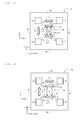
- FIG. 5A shows a plan view of an example of the sensor chip 2 (part 1).
- a semiconductor substrate particularly, a silicon (Si) single-crystal substrate with a (100) surface can be used.
- the sensor chip 2 semiconductor substrate
- four piezoresistive elements 11 (11a, 11b, 11c, 11d) are formed.
- the piezoresistive elements 11 are impurity diffused resistors formed on the surface of the semiconductor substrate.
- the conduction type of the piezoresistive elements (impurity diffused resistors) 11 is p-type.
- the direction in which a current flows in the piezoresistive elements 11 is the longitudinal direction of the piezoresistive elements 11.
- the longitudinal direction of the piezoresistive elements 11 is the direction of crystal orientation ⁇ 110> of the semiconductor substrate. Then, the longitudinal directions of the piezoresistive elements 11 (11a, 11c) are an x-axis direction (direction parallel to the sides 2d, 2e). The longitudinal directions of the piezoresistive elements 11 (11b, 11d) are a y-axis direction intersecting the x-axis direction at right angles (direction parallel to the sides 2b, 2c).
- the four piezoresistive elements 11 (11a, 11b, 11c, 11d) are connected to each other with in-chip wires 19 and thus form a Wheatstone bridge circuit 18. The four electrode pads (on the chip side) 12 are connected to the in-chip wires 19. According to such a sensor chip 2, a sense output S corresponding to the mechanical quantity of the difference between a strain (mechanical quantity) Fx in the x direction and a strain (mechanical quantity) Fy in the y direction can be outputted with high sensitivity.
- the sensor chip 2 outputs the sense output S corresponding to the mechanical quantity of the difference between the strain (mechanical quantity) Fx in the x direction and the strain (mechanical quantity) Fy in the y direction, even if the ambient temperature changes at the time of strain measurement and heat strain dependent on the difference in the coefficient of linear expansion between the sensor chip 2 and the object to be measured 4 occurs, the heat strains in the x direction and in the y direction have equal values and therefore can be canceled. That is, with the use of the sensor chip 2, there is no need to worry about change in strain values due to change in ambient temperature.
- FIG. 5B shows a plan view of an example of the sensor chip 2 (part 2).
- the example of the sensor chip 2 (part 2) is different from the example of the sensor chip 2 (part 1) in that the conduction type of the piezoresistive elements (impurity diffused resistors) 11 is n-type. Accordingly, the longitudinal direction of the piezoresistive elements 11 is the direction of crystal orientation ⁇ 100> of the semiconductor substrate. Also with such a sensor chip 2, a sense output S corresponding to the mechanical quantity of the difference between a strain (mechanical quantity) Fx in the x direction and a strain (mechanical quantity) Fy in the y direction can be outputted with high sensitivity.
- FIG. 6 shows a sectional view of a conventional mechanical quantity measuring device.
- the inventors in this application find that the reason for change in sense output with time in the conventional mechanical quantity measuring device is that strain generated in the flexible wiring board 3 is relaxed with time.
- a tensile strain is generated in the object to be measured 4
- a tensile strain is also generated in the flexible wiring board 3 attached to the object to be measured 4 and stress occurs there.
- the flexible wiring board 3 is made of a resin material such as polyimide or epoxy resin and in which a predetermined strain is applied to the resin material (flexible wiring board 3)
- stress relaxation occurs in such a manner that stress generated in the resin material (flexible wiring board 3) decreases with the lapse of time.
- FIG. 7 shows change with time in the relaxed elastic modulus of the resin material (flexible wiring board 3). It can be seen that the relaxed elastic modulus falls with the lapse of time. Even if a constant tensile strain is generated in the flexible wiring board 3 irrespective of time, as the relaxed elastic modulus falls, stress as the product of the tensile strain (quantity) and the relaxed elastic modulus falls and stress relaxation takes place. By the way, the relaxed elastic modulus falls earlier as the testing temperature (temperature of the resin material) is higher.
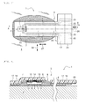
- FIG. 8 schematically shows a sectional view taken along arrows A-A in FIG. 3 .
- the size of the adhering area 7a of the adhesive 7 attaching the flexible wiring board 3 to the object to be measured 4 is the same as in the conventional mechanical quantity measuring device.
- the cutout 5 is provided, the adhering area that causes change in the sense output S is substantially the adhering area 7b and is considered smaller than in the conventional example. Therefore, change in the sense output S is successfully restrained. Also, even when an external wire from an external device is connected to the external electrode 25 (see FIG.
- the provision of the cutout 5 causes the tension to detour, instead of going straight through the flexible wiring board 3, to act on the sensor chip 2. Therefore, the influence of the tension on the sensor chip 2 can be restrained. Also, even though the cutout 5 is provided, the size of the adhering area 7a of the adhesive 7 attaching the flexible wiring board 3 to the object to be measured 4 is not much smaller than in the conventional example. The tension does not cause detachment of the flexible wiring board 3 and reliability of connection can be secured. Moreover, since the adhesive 7 in the cutout 5 rises and become fixed along the sidewalls of the flexible wiring board 3, a so-called anchor effect enables the flexible wiring board 3 to be firmly attached to the object to be measured 4.
- the cutout 5 is line-symmetrical about the center line 26 parallel to the longitudinal direction 27 of the arm portion 21.
- the cutout 5b is line-symmetrical about the center line 26.
- a width W1b of the cutout 5b in the direction intersecting the longitudinal direction 27 of the arm portion 21 substantially at right angles is bisected by the center line 26.
- the cutout 5a and the cutout 5c are line-symmetrical to each other about the center line 26.
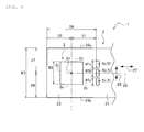
- FIG. 10 shows a plan view of a mechanical quantity measuring device 1 according to a third embodiment of the invention.
- the mechanical quantity measuring device 1 according to the third embodiment is different from the mechanical quantity measuring device 1 according to the first embodiment in that a first separate cutout 51, a second separate cutout 52 and a third separate cutout 53 are provided in flexible wiring board 3 in addition to the cutout 5.
- the first separate cutout 51 is provided opposite to cutout 5 with respect to the sensor chip 2 on the flexible wiring board 3. Of the two sides on the sensor chip 2 in the longitudinal direction 27 of the arm portion 21, the cutout 5 is arranged on one side and the first separate cutout 51 is arranged on the other.
- the second separate cutout 52 is provided between one lateral side 29a of the two sides opposite each other of the flexible wiring board 3 along the longitudinal direction 27 of the arm portion 21, and the sensor chip 2.
- the third separate cutout 53 is provided between the other lateral side 29b of the two sides opposite each other of the flexible wiring board 3 along the longitudinal direction 27 of the arm portion 21, and the sensor chip 2.
- the second separate cutout 52 is arranged on one side and the third separate cutout 53 is arranged on the other.
- FIG. 11 shows the state around the sensor chip 2 in the mechanical quantity measuring device 1 according to the third embodiment.
- the cutout 5 faces the side 2b of the sensor chip 2.
- the longitudinal direction of the cutout 5 is substantially parallel to the side 2b.
- the width W1 of the cutout 5 in the longitudinal direction is substantially equal to or greater than the length (width) W2 of the side 2b (W1 ⁇ W2).
- the first separate cutout 51 faces the side 2c of the sensor chip 2.
- the longitudinal direction of the first separate cutout 51 is substantially parallel to the side 2c.
- the second separate cutout 52 faces the side 2d of the sensor chip 2.
- the longitudinal direction of the second separate cutout 52 is substantially parallel to the side 2d.
- the third separate cutout 53 faces the side 2e of the sensor chip 2.
- the longitudinal direction of the third separate cutout 53 is substantially parallel to the side 2e.
- FIG. 12 shows a sectional view around the sensor chip 2 and around the external electrode 25 in the mechanical quantity measuring device 1 according to the third embodiment of the invention in the case where the mechanical quantity measuring device 1 is attached to the object to be measured 4 with the adhesive 7.
- the section in the sectional view of FIG. 12 corresponds to a section taken along arrows A-A in FIG. 10 .
- the first separate cutout 51 is provided opposite the cutout 5 with respect to the sensor chip 2 on the flexible wiring board 3. Of the two sides on the sensor chip 2 in the longitudinal direction 27 of the arm portion 21, the cutout 5 is arranged on one side and the first separate cutout 51 is arranged on the other.
- the cutouts 5, 51 are provided on both sides of the sensor chip 2, symmetry is increased and stress acting on the sensor chip 2 from the flexible wiring board 3 can be uniform.
- the adhesive 7 rises and becomes fixed along the sidewalls of the flexible wiring board 3. Therefore, a so-called anchor effect from the two sides enables firm and uniform attachment of the flexible wiring board 3 to the object to be measured 4 at the position supporting the sensor chip 2.
- FIG. 13 shows a sectional view around the sensor chip 2 in the mechanical quantity measuring device 1 according to the third embodiment of the invention in the case where the mechanical quantity measuring device 1 is attached to the object to be measured 4 with the adhesive 7.
- the section in the sectional view of FIG. 13 corresponds to a section taken along arrows B-B in FIG. 10 .
- the second separate cutout 52 is arranged on one side and the third separate cutout 53 is arranged on the other. Since the cutouts 52, 53 are provided on both sides of the sensor chip 2, symmetry is increased and stress acting on the sensor chip 2 from the flexible wiring board 3 can be uniform.
- the adhesive 7 rises and becomes fixed along the sidewalls of the flexible wiring board 3. Therefore, a so-called anchor effect from the two sides enables firm and uniform attachment of the flexible wiring board 3 to the object to be measured 4 at the position supporting the sensor chip 2.
- the third embodiment can achieve similar advantages to the first embodiment.
- the cutout 5 and the first separate cutout 51 (second separate cutout 52, third separate cutout 53) can be easily made closer to the sensor chip 2 and the substantial adhering area 7b that causes change in the sense output S can be made smaller than in the first embodiment without reducing the adhering area 7a.
- FIG. 15 shows a plan view of a mechanical quantity measuring device 1 according to a fourth embodiment of the invention.
- FIG. 16 shows an enlarged view around the sensor chip 2 of the mechanical quantity measuring device 1.
- the cutout 5 is divided into plural cutouts, as in the mechanical quantity measuring device 1 according to the second embodiment.
- the mechanical quantity measuring device 1 according to the fourth embodiment is different from the mechanical quantity measuring device 1 according to the second embodiment in that the divided cutouts 5a and 5c reach the lateral sides 29a and 29b of the flexible wiring board 3.
- the flexible wiring board is cut into from the lateral sides 29a, 29b, thus forming the cutouts 5a, 5c on the lateral sides 29a, 29b.
- One-side ends of the cutouts 5a, 5c in the longitudinal direction 28 are arcuate.
- the cutouts 5a, 5c are arranged in a line along the longitudinal direction 28 of the cutout 5.
- the longitudinal directions of the cutouts 5a, 5c are substantially coincident with the longitudinal direction 28 of the cutout 5.
- the cutouts 5a, 5c are line-symmetrical to each other about the center line 26 parallel to the longitudinal direction 27 of the arm portion 21.
- the wires 6 (see FIG. 1A ) can pass between the cutout 5a and the cutout 5c without detouring around the cutout 5. Therefore, the degree of freedom in designing the wires 6 can be improved, as in the second embodiment.
Landscapes
- Physics & Mathematics (AREA)
- General Physics & Mathematics (AREA)
- Pressure Sensors (AREA)
- Force Measurement Appropriate To Specific Purposes (AREA)
- Measurement Of Length, Angles, Or The Like Using Electric Or Magnetic Means (AREA)
Abstract
Description
- The present invention relates to a mechanical quantity measuring device in which a sensor chip is supported on a flexible wiring board.
- A mechanical quantity measuring device can be attached to an object to be measured and thus can measure a mechanical quantity acting on the object to be measured. As this mechanical quantity measuring device, a device which uses a sensor chip applying an effect of resistance that varies depending on the strain (piezoresistive effect) is proposed. An impurity diffused resistor is formed on a surface of this sensor chip and the sensor chip is attached to an object to be measured, with an adhesive. When a mechanical quantity acts on the object to be measured and the object to be measured is strained, the impurity diffused resistor is strained via the adhesive and the resistance thereof changes. Therefore, this change in resistance can be outputted as a sense output and the mechanical quantity (strain) acting on the object to be measured can be detected.
- In order to achieve widespread use of this sensor chip, it is important that the sensor chip can be easily attached to an object to be measured and that a sense output can be taken out securely. In response to such demand, a mechanical quantity measuring device in which a sensor chip is deposited on a flexible wiring board having a wire and in which the sensor chip is electrically connected to the wire, is proposed (see
PTL 1 and the like). By thus forming a module including the sensor chip and the flexible wiring board, the device can be easier to handle than in the case where the sensor chip is provided singly. - PTL 1:
JP-A-2001-264188 - In the conventional mechanical quantity measuring device, since the sensor chip is deposited on the flexible wiring board, not only the sensor chip but also the flexible wiring board around the sensor chip is attached to the object to be measured so that tension from an external wire connected to the flexible wiring board will not act on the sensor chip. In such a conventional mechanical quantity measuring device, the sense output may change with time in some cases.
- Thus, an object of the invention is to provide a mechanical quantity measuring device capable of restraining change in sense output with time.
- In order to achieve the foregoing object, according to the invention, a mechanical quantity measuring device includes a sensor chip which outputs a sense output corresponding to a mechanical quantity acting on the object to be measured, and a flexible wiring board which supports the sensor chip and has a wire to lead out the sense output to outside, and in measuring the mechanical quantity, the sensor chip and the flexible wiring board are attached to the object to be measured.
- The mechanical quantity measuring device is characterized in that a cutout is provided on the flexible wiring board near the sensor chip and on the side where the wire is arranged for the sensor chip.
- According to the invention, a mechanical quantity measuring device capable of restraining change in sense output with time can be provided.
-
- [
FIG. 1A] FIG. 1A is a plan view of a mechanical quantity measuring device according to a first embodiment of the invention. - [
FIG. 1B] FIG. 1B is a bottom view of the mechanical quantity measuring device according to the first embodiment of the invention. - [
FIG. 2] FIG. 2 is an enlarged view ofFIG. 1A around a sensor chip in the mechanical quantity measuring device according to the first embodiment of the invention. - [
FIG. 3] FIG. 3 is a plan view where the mechanical quantity measuring device according to the first embodiment of the invention is attached to an object to be measured, with an adhesive. - [
FIG. 4] FIG. 4 is an enlarged sectional view taken along arrows A-A inFIG. 3 . - [
FIG. 5A] FIG. 5A is a plan view of an example of a sensor chip (part 1). - [
FIG. 5B] FIG. 5B is a plan view of an example of a sensor chip (part 2). - [
FIG. 6] FIG. 6 is a sectional view of a conventional mechanical quantity measuring device. - [
FIG. 7] FIG. 7 is a graph showing change in relaxed elastic modulus with time, in order to explain a stress relaxation phenomenon in a flexible wiring board. - [
FIG. 8] FIG. 8 is a schematic sectional view taken along arrows A-A inFIG. 3 . - [
FIG. 9] FIG. 9 is an enlarged view around a sensor chip in a mechanical quantity measuring device according to a second embodiment of the invention. - [
FIG. 10] FIG. 10 is a plan view of a mechanical quantity measuring device according to a third embodiment of the invention. - [
FIG. 11] FIG. 11 is an enlarged view ofFIG. 10 around a sensor chip in the mechanical quantity measuring device according to the third embodiment. - [
FIG. 12] FIG. 12 is a sectional view corresponding to a section taken along arrows A-A inFIG. 10 in the case where the mechanical quantity measuring device is attached to an object to be measured, with an adhesive, around the sensor chip and around an external electrode in the mechanical quantity measuring device according the third embodiment of the invention. - [
FIG. 13] FIG. 13 is a sectional view corresponding to a section taken along arrows B-B inFIG. 10 in the case where the mechanical quantity measuring device is attached to an object to be measured, with an adhesive, around the sensor chip in the mechanical quantity measuring device according to the third embodiment of the invention. - [
FIG. 14] FIG. 14 is a schematic sectional view corresponding to a section taken along arrows A-A inFIG. 10 in the case where the mechanical quantity measuring device according to the third embodiment of the invention is attached to an object to be measured, with an adhesive. - [
FIG. 15] FIG. 15 is a plan view of a mechanical quantity measuring device according to a fourth embodiment of the invention. - [
FIG. 16] FIG. 16 is an enlarged view ofFIG. 15 around a sensor chip in the mechanical quantity measuring device according to the fourth embodiment of the invention. - In the following embodiments, explanation of the same or similar part will not be repeated in principle unless particularly necessary. Moreover, in the following embodiments, though the description will be divided into plural sections or embodiments when necessary for convenience, these sections or embodiments are not unrelated to each other and one may be a modification example, details, or supplementary explanation of a part or the whole of the other, unless otherwise stated. Also, in the following embodiments, when the numbers of elements or the like (including the numbers of elements, numeric values, quantities, ranges and the like) are mentioned, possible numbers are not limited to the specific numbers and may be equal to or greater than the specific numbers, or equal to or smaller than the specific numbers, unless otherwise stated or unless limitation to the specific numbers is theoretically obvious. Also, in the following embodiments, as a matter of course, components thereof are not necessarily essential unless otherwise stated or unless it is theoretically clear that the components are essential. Moreover, in the following embodiments, when the expressions "made up of A", "formed by A", "having A" and "including A" are used with respect to components or the like, as a matter of course, other components are not excluded unless it is clearly stated that only such components are used. Similarly, in the following embodiments, when shapes, positional relations and the like of components or the like are mentioned, substantially approximate or similar shapes and the like are included unless otherwise stated or unless it is theoretically clearly considered otherwise. This also applies the numeric values and ranges.
- Hereinafter, embodiments of the invention will be described in detail, based on the drawings. Meanwhile, in all the drawings for explaining the embodiments, members having the same functions are denoted by the same reference numerals and repetitive explanation thereof is omitted. Also, the invention is not limited to each of the plural embodiments employed here and may properly combine those embodiments.
-
FIG. 1A shows a plan view of a mechanicalquantity measuring device 1 according to a first embodiment of the invention. The mechanicalquantity measuring device 1 has asensor chip 2 and aflexible wiring board 3 supporting thesensor chip 2. Thesensor chip 2 can output a sense output S corresponding to a mechanical quantity acting on an object to be measured 4 (seeFIG. 3 ). - The
flexible wiring board 3 has awire 6 and anexternal electrode 25 electrically connected to thewire 6. Thewire 6 is electrically connected to thesensor chip 2 and leas out a sense output S from thesensor chip 2. Theexternal electrode 25 outputs the sense output S from thewire 6 to outside. - Also, the
flexible wiring board 3 has anarm portion 21 and abase portion 24 connected to thearm portion 21. Thearm portion 21 supports thesensor chip 2 at adistal end part 22 thereof and is connected to thebase portion 24 at aroot part 23 thereof. Thewire 6 is laid from thedistal end part 22 to theroot part 23 of thearm portion 21. In thebase portion 24, theexternal electrode 25 connected to thewire 6 is provided. Theflexible wiring board 3 is used in a number of semiconductor packaged products, utilizing its excellent flexibility. Also, the flexible wiring board can be reduced in thickness to 100 µm or below and enables reduction in size of the wiring portion and therefore is an essential component of a portable electronic device. - The
flexible wiring board 3 is provided with a cutout (slit) 5. The cutout (slit) 5 is provided in theflexible wiring board 3 between thesensor chip 2 and theexternal electrode 25. The cutout (slit) 5 is provided in theflexible wiring board 3 near thesensor chip 2 and on the side where thewire 6 is arranged for thesensor chip 2. Thecutout 5 is provided on the side of theexternal electrode 25 with respect to thesensor chip 2, in alongitudinal direction 27 of thearm portion 21 that is a direction from thedistal end part 22 toward theroot part 23 of thearm portion 21. Alongitudinal direction 28 of thecutout 5 intersects thelongitudinal direction 27 of thearm portion 21 substantially at right angles. Thelongitudinal direction 28 of thecutout 5 intersects, substantially at right angles, acenter line 26 of thearm portion 21 that is parallel to thelongitudinal direction 27 of thearm portion 21. Meanwhile, thecutout 5 can be produced by punching with a metal press mold, similarly to the formation of the outer shape of theflexible wiring board 3, and therefore is not a factor that increases cost. - The
sensor chip 2 is arranged in such a way that acenter point 2a thereof is situated on thecenter line 26 of thearm portion 21. Also, thesensor chip 2 is arranged with line symmetry about thecenter line 26 of thearm portion 21. - As the
wire 6, plural wires (in the example ofFIG. 1A , four wires) are laid. Theplural wires 6 are drawn to detour around thecutout 5. Theplural wires 6 are arranged with line symmetry to each other about thecenter line 26 of thearm portion 21. - Meanwhile, on the face side of the mechanical quantity measuring device 1 (flexible wiring board 3), a
base film 17 is exposed almost across the entire surface. -
FIG. 1B shows a bottom view of the mechanicalquantity measuring device 1 according to the first embodiment of the invention. Thesensor chip 2 is supported on the back side of theflexible wiring board 3. Thewires 6 are formed below thebase film 17 and are also covered with an insulatingfilm 16. That is, thewires 6 are covered with thebase film 17 from the face side of theflexible wiring board 3 and are covered with the insulatingfilm 16 from the back side of theflexible wiring board 3. Theexternal electrode 25 is formed below thebase film 17. The lower side of theexternal electrode 25 is exposed, instead of being covered with the insulatingfilm 16, and is connectable to an external device. -
FIG. 2 shows an enlarged view around thesensor chip 2 in the mechanicalquantity measuring device 1 according to the first embodiment of the invention. Both ends in thelongitudinal direction 28 of thecutout 5 are arcuate. Thecutout 5 is line-symmetrical about thecenter line 26 parallel to thelongitudinal direction 27 of thearm portion 21. A width W1 of thecutout 5 in the direction intersecting thelongitudinal direction 27 of thearm portion 21 substantially at right angles is bisected by thecenter line 26 of thearm portion 21. The width W1 of thecutout 5 in the direction intersecting thelongitudinal direction 27 of thearm portion 21 substantially at right angles is substantially equal to or greater than a width W2 of thesensor chip 2 in the direction intersecting thelongitudinal direction 27 of thearm portion 21 substantially at right angles (W1≥W2). - The
center point 2a of thesensor chip 2 is arranged on thecenter line 26 parallel to thelongitudinal direction 27 of thearm portion 21. A distance D7 from alateral side 29a of theflexible wiring board 3 along thelongitudinal direction 27 of thearm portion 21 to thecenter point 2a of thesensor chip 2 is substantially equal to a distance D8 from alateral side 29b of theflexible wiring board 3 along thelongitudinal direction 27 of thearm portion 21 to thecenter point 2a of the sensor chip 2 (D7=D8). - The
sensor chip 2 is substantially square, as viewed in a plan view. Aside 2b is arranged facing thecutout 5. Aside 2c is arranged parallel to and facing the end side on thedistal end part 22 of thearm portion 21. Aside 2d is arranged parallel to and facing thelateral side 29a of theflexible wiring board 3 along thelongitudinal direction 27 of thearm portion 21. Aside 2e is arranged parallel to and facing thelateral side 29b of theflexible wiring board 3 along thelongitudinal direction 27 of thearm portion 21. Theside 2b of thesensor chip 2 that faces thecutout 5 intersects thecenter line 26 of thearm portion 21 substantially at right angles. Thelongitudinal direction 28 of thecutout 5 intersects the longitudinal direction 27 (center line 26) of thearm portion 21 substantially at right angles. Then, thelongitudinal direction 28 of thecutout 5 is arranged parallel to theside 2b. - A distance D1 from the
cutout 5 to thecenter point 2a of thesensor chip 2 is substantially equal to a distance D2 from the end side of theflexible wiring board 3 opposite to thecutout 5 with respect to thesensor chip 2 to thecenter point 2a of the sensor chip 2 (D1=D2). A distance D6 from thecutout 5 to the end side of theflexible wiring board 3 opposite to theexternal electrode 25 with respect to thecutout 5 is substantially equal to a width W3 of thearm portion 21 in the direction intersecting thelongitudinal direction 27 of thearm portion 21 substantially at right angles at thecenter point 2a of the sensor chip 2 (D6=W3). The distance D1 from thecutout 5 to thecenter point 2a of thesensor chip 2 is substantially equal to the distance D7 from thelateral side 29a to thecenter point 2a of thesensor chip 2 and the distance D8 from thelateral side 29b to thecenter point 2a of the sensor chip 2 (D1=D7=D8). The distance D1 from thecutout 5 to thecenter point 2a of thesensor chip 2 is substantially equal to half the width W3 of thearm portion 21 in the direction intersecting thelongitudinal direction 27 of thearm portion 21 substantially at right angles at thecenter point 2a of thesensor chip 2. - Also, in the first embodiment, while an example of the
sensor chip 2 that is square as viewed in a plan view is described, its shape is not limited to this and may be, for example, rectangular or circle as long as thecenter point 2a can be decided. -
FIG. 3 shows the state where the mechanicalquantity measuring device 1 according to the first embodiment of the invention is attached to an object to be measured 4 with an adhesive 7. In the mechanicalquantity measuring device 1, when measuring a mechanical quantity, thesensor chip 2 and theflexible wiring board 3 are attached to the object to be measured 4 with the adhesive 7. The adhesive 7 is applied not only to thedistal end part 22 of thearm portion 21 around thesensor chip 2 but also to an area from thedistal end part 22 of thearm portion 21 to the vicinity of theroot part 23. Anadhesive end surface 7c of the adhesive 7 reaches the vicinity of theroot part 23 of thearm portion 21. The adhesive 7 is not applied to thebase portion 24 of theflexible wiring board 3. Even when an external wire from an external device is connected to theexternal electrode 25 and tension from the external wire acts on theexternal electrode 25, the action of tension on thesensor chip 2 is restrained because theflexible wiring board 3 between theexternal electrode 25 and thesensor chip 2 is attached to the object to be measured 4. By the way, as the adhesive 7, a two-component or single-component epoxy resin adhesive or the like may be used. -
FIG. 4 shows an enlarged view of essential parts of a sectional view taken along arrows A-A inFIG. 3 . Plural electrode pads (on the chip side) 12 are formed on the surface of thesensor chip 2. On the back side of thebase film 17 opposite theplural electrodes pads 12, plural electrode pads (on the flexible wiring board side) 15 are formed. Theplural electrode pads 15 are connected to thewires 6. The electrode pads (on the chip side) 12 and the electrode pads (on the flexible wiring board side) 15 are connected to each other withbumps 13 such as gold bumps. The area between thesensor chip 2 and theflexible wiring board 3 except thebumps 13 is filled with anunderfill material 14. In this way, thesensor chip 2 is attached to and supported on theflexible wiring board 3 with thebumps 13 and particularly with theunderfill material 14. An epoxy resin can be used as theunderfill material 14. Theunderfill material 14 is used for the purpose of preventing a short circuit between thebumps 13 and between theelectrode pads sensor chip 2, and reinforcing the bonding force between theflexible wiring board 3 and thesensor chip 2. - In the
flexible wiring board 3, thewires 6 are formed on the back side of thebase film 17, and the insulatingfilm 16 is formed under thewires 6. Theflexible wiring board 3 has a sandwich structure in which thewires 6 are sandwiched between thebase film 17 and the insulatingfilm 16. -
FIG. 5A shows a plan view of an example of the sensor chip 2 (part 1). As thesensor chip 2, a semiconductor substrate, particularly, a silicon (Si) single-crystal substrate with a (100) surface can be used. On the sensor chip 2 (semiconductor substrate), four piezoresistive elements 11 (11a, 11b, 11c, 11d) are formed. Thepiezoresistive elements 11 are impurity diffused resistors formed on the surface of the semiconductor substrate. The conduction type of the piezoresistive elements (impurity diffused resistors) 11 is p-type. The direction in which a current flows in thepiezoresistive elements 11 is the longitudinal direction of thepiezoresistive elements 11. The longitudinal direction of thepiezoresistive elements 11 is the direction of crystal orientation <110> of the semiconductor substrate. Then, the longitudinal directions of the piezoresistive elements 11 (11a, 11c) are an x-axis direction (direction parallel to thesides sides chip wires 19 and thus form aWheatstone bridge circuit 18. The four electrode pads (on the chip side) 12 are connected to the in-chip wires 19. According to such asensor chip 2, a sense output S corresponding to the mechanical quantity of the difference between a strain (mechanical quantity) Fx in the x direction and a strain (mechanical quantity) Fy in the y direction can be outputted with high sensitivity. - Meanwhile, in order to amplify the sense output S, it is possible to form an amplifier circuit on the surface of the
sensor chip 2 forming theWheatstone bridge circuit 18. All of theWheatstone bridge circuit 18, the amplifier circuit and the like formed on the sensor chip can be produced using a normal semiconductor manufacturing process. Therefore, refinement is easy and the manufacturing cost can be reduced. - Also, since the
sensor chip 2 outputs the sense output S corresponding to the mechanical quantity of the difference between the strain (mechanical quantity) Fx in the x direction and the strain (mechanical quantity) Fy in the y direction, even if the ambient temperature changes at the time of strain measurement and heat strain dependent on the difference in the coefficient of linear expansion between thesensor chip 2 and the object to be measured 4 occurs, the heat strains in the x direction and in the y direction have equal values and therefore can be canceled. That is, with the use of thesensor chip 2, there is no need to worry about change in strain values due to change in ambient temperature. - Also, as described with reference to
FIG. 2 , the distance D6 from thecutout 5 to the end side and the width W3 of thearm portion 21 are substantially equal (D6=W3). Therefore, the size of a substantial adheringarea 7b, described in the explanation ofFIG. 8 , is equal in the x direction and in the y direction of thesensor chip 2. Since stress to be relaxed is equal in the x direction and in the y direction of thesensor chip 2, the stress to be relaxed can be canceled, as in the case of change in ambient temperature. -
FIG. 5B shows a plan view of an example of the sensor chip 2 (part 2). The example of the sensor chip 2 (part 2) is different from the example of the sensor chip 2 (part 1) in that the conduction type of the piezoresistive elements (impurity diffused resistors) 11 is n-type. Accordingly, the longitudinal direction of thepiezoresistive elements 11 is the direction of crystal orientation <100> of the semiconductor substrate. Also with such asensor chip 2, a sense output S corresponding to the mechanical quantity of the difference between a strain (mechanical quantity) Fx in the x direction and a strain (mechanical quantity) Fy in the y direction can be outputted with high sensitivity. -
FIG. 6 shows a sectional view of a conventional mechanical quantity measuring device. The inventors in this application find that the reason for change in sense output with time in the conventional mechanical quantity measuring device is that strain generated in theflexible wiring board 3 is relaxed with time. When a tensile strain is generated in the object to be measured 4, a tensile strain is also generated in theflexible wiring board 3 attached to the object to be measured 4 and stress occurs there. When a test is carried out in which theflexible wiring board 3 is made of a resin material such as polyimide or epoxy resin and in which a predetermined strain is applied to the resin material (flexible wiring board 3), stress relaxation occurs in such a manner that stress generated in the resin material (flexible wiring board 3) decreases with the lapse of time. -
FIG. 7 shows change with time in the relaxed elastic modulus of the resin material (flexible wiring board 3). It can be seen that the relaxed elastic modulus falls with the lapse of time. Even if a constant tensile strain is generated in theflexible wiring board 3 irrespective of time, as the relaxed elastic modulus falls, stress as the product of the tensile strain (quantity) and the relaxed elastic modulus falls and stress relaxation takes place. By the way, the relaxed elastic modulus falls earlier as the testing temperature (temperature of the resin material) is higher. - As shown in
FIG. 6 , when the stress generated in the flexible wiring board 3 (resin material) is relaxed, the strain state of the object to be measured 4 with theflexible wiring board 3 attached thereto changes and the strain state of thesensor chip 2, supported on theflexible wiring board 3 and attached to the object to be measured 4, changes. That is, the stress relaxation in theflexible wiring board 3 results in change in the sense output S from thesensor chip 2. Then, the amount of change in this sense output S increases as an adheringarea 7a of the adhesive 7 attaching theflexible wiring board 3 to object to be measured 4 is greater. -
FIG. 8 schematically shows a sectional view taken along arrows A-A inFIG. 3 . Even in the mechanicalquantity measuring device 1 of the first embodiment, the size of the adheringarea 7a of the adhesive 7 attaching theflexible wiring board 3 to the object to be measured 4 is the same as in the conventional mechanical quantity measuring device. However, since thecutout 5 is provided, the adhering area that causes change in the sense output S is substantially the adheringarea 7b and is considered smaller than in the conventional example. Therefore, change in the sense output S is successfully restrained. Also, even when an external wire from an external device is connected to the external electrode 25 (seeFIG. 3 ) and tension from the external wire acts on theflexible wiring board 3 with theexternal electrode 25 formed thereon, the provision of thecutout 5 causes the tension to detour, instead of going straight through theflexible wiring board 3, to act on thesensor chip 2. Therefore, the influence of the tension on thesensor chip 2 can be restrained. Also, even though thecutout 5 is provided, the size of the adheringarea 7a of the adhesive 7 attaching theflexible wiring board 3 to the object to be measured 4 is not much smaller than in the conventional example. The tension does not cause detachment of theflexible wiring board 3 and reliability of connection can be secured. Moreover, since the adhesive 7 in thecutout 5 rises and become fixed along the sidewalls of theflexible wiring board 3, a so-called anchor effect enables theflexible wiring board 3 to be firmly attached to the object to be measured 4. - Also, as described with reference to
FIG. 2 , since the distance D6 from thecutout 5 to the end side and the width W3 of thearm portion 21 are substantially equal (D6=W3), the size of the substantial adheringarea 7b which causes change in the sense output S is equal in the x direction and in the y direction of the sensor chip 2 (seeFIG. 5A ). As stress to be relaxed is equal in the x direction and in the y direction of thesensor chip 2, the sense output S in which the stress to be relaxed is canceled can be outputted. -
FIG. 9 shows an enlarged view around asensor chip 2 in a mechanicalquantity measuring device 1 according to a second embodiment of the invention. The mechanicalquantity measuring device 1 according to the second embodiment is different from the mechanicalquantity measuring device 1 according to the first embodiment in that thecutout 5 is divided into plural parts.FIG. 9 shows an example of thecutout 5 divided into threecutouts longitudinal direction 28 of thecutouts cutouts longitudinal direction 28 of thecutout 5. The longitudinal direction of thecutouts longitudinal direction 28 of thecutout 5. The cutout 5 (5a, 5b, 5c) is line-symmetrical about thecenter line 26 parallel to thelongitudinal direction 27 of thearm portion 21. Specifically, thecutout 5b is line-symmetrical about thecenter line 26. A width W1b of thecutout 5b in the direction intersecting thelongitudinal direction 27 of thearm portion 21 substantially at right angles is bisected by thecenter line 26. Thecutout 5a and thecutout 5c are line-symmetrical to each other about thecenter line 26. A width W1a of thecutout 5a in the direction intersecting thelongitudinal direction 27 of thearm portion 21 substantially at right angles is substantially equal to a width W1c of thecutout 5c in the direction intersecting thelongitudinal direction 27 of thearm portion 21 substantially at right angles (W1a=W1c). According to the second embodiment, not only the advantages of the first embodiment can be achieved but also the degree of freedom in designing thewires 6 can be improved because the wires 6 (seeFIG. 1A ) can not only detour thecutout 5 but also pass between thecutouts -
FIG. 10 shows a plan view of a mechanicalquantity measuring device 1 according to a third embodiment of the invention. The mechanicalquantity measuring device 1 according to the third embodiment is different from the mechanicalquantity measuring device 1 according to the first embodiment in that a firstseparate cutout 51, a secondseparate cutout 52 and a thirdseparate cutout 53 are provided inflexible wiring board 3 in addition to thecutout 5. - The first
separate cutout 51 is provided opposite tocutout 5 with respect to thesensor chip 2 on theflexible wiring board 3. Of the two sides on thesensor chip 2 in thelongitudinal direction 27 of thearm portion 21, thecutout 5 is arranged on one side and the firstseparate cutout 51 is arranged on the other. - The second
separate cutout 52 is provided between onelateral side 29a of the two sides opposite each other of theflexible wiring board 3 along thelongitudinal direction 27 of thearm portion 21, and thesensor chip 2. - The third
separate cutout 53 is provided between the otherlateral side 29b of the two sides opposite each other of theflexible wiring board 3 along thelongitudinal direction 27 of thearm portion 21, and thesensor chip 2. Of the two sides on thesensor chip 2 in the direction intersecting thelongitudinal direction 27 of thearm portion 21 at right angles, the secondseparate cutout 52 is arranged on one side and the thirdseparate cutout 53 is arranged on the other. -
FIG. 11 shows the state around thesensor chip 2 in the mechanicalquantity measuring device 1 according to the third embodiment. Thecutout 5 faces theside 2b of thesensor chip 2. The longitudinal direction of thecutout 5 is substantially parallel to theside 2b. The width W1 of thecutout 5 in the longitudinal direction is substantially equal to or greater than the length (width) W2 of theside 2b (W1≥W2). - The first
separate cutout 51 faces theside 2c of thesensor chip 2. The longitudinal direction of the firstseparate cutout 51 is substantially parallel to theside 2c. A width W4 of the firstseparate cutout 51 in the longitudinal direction is substantially equal to or greater than the length (width) of theside 2c (=W2) (W4≥W2). The width W4 is substantially equal to the width W1 of thecutout 5 in the longitudinal direction (W4=W1). - The second
separate cutout 52 faces theside 2d of thesensor chip 2. The longitudinal direction of the secondseparate cutout 52 is substantially parallel to theside 2d. A width W5 of the secondseparate cutout 52 in the longitudinal direction is substantially equal to or greater than the length (width) of theside 2d (=W2) (W5≥W2). - The third
separate cutout 53 faces theside 2e of thesensor chip 2. The longitudinal direction of the thirdseparate cutout 53 is substantially parallel to theside 2e. A width W6 of the thirdseparate cutout 53 in the longitudinal direction is substantially equal to or greater than the length (width) of theside 2e (=W2) (W6≥W2). The width W6 is substantially equal to the width W5 of the secondseparate cutout 52 in the longitudinal direction (W6=W5). The width W5 and the width W6 are substantially equal to the width W1 of thecutout 5 in the longitudinal direction (W5=W6=W1). - A distance D3 from the first
separate cutout 51 to thecenter point 2a of thesensor chip 2 is substantially equal to the distance D1 from thecutout 5 to thecenter point 2a of the sensor chip 2 (D3=D1). A distance D4 from the secondseparate cutout 52 to thecenter point 2a of thesensor chip 2 is substantially equal to a distance D5 from the thirdseparate cutout 53 to thecenter point 2a of the sensor chip 2 (D4=D5). Also, the distance D4 and the distance D5 are substantially equal to the distance D1 (D4=D5=D1). The distance D6 from thecutout 5 to the firstseparate cutout 51 is substantially equal to a distance D9 from the secondseparate cutout 52 to the third separate cutout 53 (D6=D9). -
FIG. 12 shows a sectional view around thesensor chip 2 and around theexternal electrode 25 in the mechanicalquantity measuring device 1 according to the third embodiment of the invention in the case where the mechanicalquantity measuring device 1 is attached to the object to be measured 4 with the adhesive 7. The section in the sectional view ofFIG. 12 corresponds to a section taken along arrows A-A inFIG. 10 . The firstseparate cutout 51 is provided opposite thecutout 5 with respect to thesensor chip 2 on theflexible wiring board 3. Of the two sides on thesensor chip 2 in thelongitudinal direction 27 of thearm portion 21, thecutout 5 is arranged on one side and the firstseparate cutout 51 is arranged on the other. Since thecutouts sensor chip 2, symmetry is increased and stress acting on thesensor chip 2 from theflexible wiring board 3 can be uniform. Particularly, in thecutout 5 and the firstseparate cutout 51, the adhesive 7 rises and becomes fixed along the sidewalls of theflexible wiring board 3. Therefore, a so-called anchor effect from the two sides enables firm and uniform attachment of theflexible wiring board 3 to the object to be measured 4 at the position supporting thesensor chip 2. -
FIG. 13 shows a sectional view around thesensor chip 2 in the mechanicalquantity measuring device 1 according to the third embodiment of the invention in the case where the mechanicalquantity measuring device 1 is attached to the object to be measured 4 with the adhesive 7. The section in the sectional view ofFIG. 13 corresponds to a section taken along arrows B-B inFIG. 10 . Of the two sides on thesensor chip 2 in the direction intersecting thelongitudinal direction 27 of thearm portion 21 at right angles, the secondseparate cutout 52 is arranged on one side and the thirdseparate cutout 53 is arranged on the other. Since thecutouts sensor chip 2, symmetry is increased and stress acting on thesensor chip 2 from theflexible wiring board 3 can be uniform. Particularly, in the secondseparate cutout 52 and the thirdseparate cutout 53, the adhesive 7 rises and becomes fixed along the sidewalls of theflexible wiring board 3. Therefore, a so-called anchor effect from the two sides enables firm and uniform attachment of theflexible wiring board 3 to the object to be measured 4 at the position supporting thesensor chip 2. -
FIG. 14 schematically shows a sectional view in the case where the mechanicalquantity measuring device 1 according to the third embodiment of the invention is attached to the object to be measured 4 with the adhesive 7. The section in the sectional view ofFIG. 14 corresponds to a section taken along arrows A-A inFIG. 10 . Even in the mechanicalquantity measuring device 1 according to the third embodiment, the size of the adheringarea 7a of the adhesive 7 attaching theflexible wiring board 3 to the object to be measured 4 is the same as in the conventional mechanical quantity measuring device (seeFIG. 6 ). However, since thecutout 5 and the first separate cutout 51 (secondseparate cutout 52, third separate cutout 53) are provided, the adhering area that causes change in the sense output S is substantially the adheringarea 7b and is considered smaller than in the conventional example. Therefore, change in the sense output S is successfully restrained. In this way, the third embodiment can achieve similar advantages to the first embodiment. In the third embodiment, thecutout 5 and the first separate cutout 51 (secondseparate cutout 52, third separate cutout 53) can be easily made closer to thesensor chip 2 and the substantial adheringarea 7b that causes change in the sense output S can be made smaller than in the first embodiment without reducing the adheringarea 7a. - Also, as described with reference to
FIG. 11 , the distance D6 from thecutout 5 to the firstseparate cutout 51 is substantially equal to the distance D9 from the secondseparate cutout 52 to the third separate cutout 53 (D6=D9). Therefore, the size of the substantial adheringarea 7b that causes change in the sense output S is equal in the x direction and in the y direction of the sensor chip 2 (seeFIG. 5A ). Since stress to be relaxed is equal in the x direction and in the y direction of thesensor chip 2, the sense output S in which the stress to be relaxed is canceled can be outputted. -
FIG. 15 shows a plan view of a mechanicalquantity measuring device 1 according to a fourth embodiment of the invention.FIG. 16 shows an enlarged view around thesensor chip 2 of the mechanicalquantity measuring device 1. In the mechanicalquantity measuring device 1 according to the fourth embodiment, thecutout 5 is divided into plural cutouts, as in the mechanicalquantity measuring device 1 according to the second embodiment. However, the mechanicalquantity measuring device 1 according to the fourth embodiment is different from the mechanicalquantity measuring device 1 according to the second embodiment in that the dividedcutouts lateral sides flexible wiring board 3. As for this point, it can also be considered that the flexible wiring board is cut into from thelateral sides cutouts lateral sides - One-side ends of the
cutouts longitudinal direction 28 are arcuate. Thecutouts longitudinal direction 28 of thecutout 5. The longitudinal directions of thecutouts longitudinal direction 28 of thecutout 5. Thecutouts center line 26 parallel to thelongitudinal direction 27 of thearm portion 21. The width W1a of thecutout 5a in the direction intersecting thelongitudinal direction 27 of thearm portion 21 substantially at right angles is substantially equal to the width W1c of thecutout 5c in the direction intersecting thelongitudinal direction 27 of thearm portion 21 substantially at right angles (W1a=W1c). According to the fourth embodiment, the wires 6 (seeFIG. 1A ) can pass between thecutout 5a and thecutout 5c without detouring around thecutout 5. Therefore, the degree of freedom in designing thewires 6 can be improved, as in the second embodiment. -
- 1
- mechanical quantity measuring device
- 2
- sensor chip
- 2a
- center point of sensor chip
- 2b, 2c, 2d, 2e
- lateral sides of sensor chip
- 3
- flexible wiring board
- 4
- object to be measured
- 5
- cutout
- 5a, 5b, 5c
- plural divided cutouts
- 6
- wire
- 7
- adhesive
- 7a, 7b
- adhering area
- 7c
- adhering end surface
- 11, 11a, 11b, 11c, 11d
- piezoresistive element
- 12
- electrode pad (chip side)
- 13
- bump
- 14
- underfill material
- 15
- electrode pad (flexible wiring board side)
- 16
- insulating film
- 17
- base film
- 18
- Wheatstone bridge circuit
- 19
- in-chip wire
- 21
- arm portion
- 22
- distal end part
- 23
- root part
- 24
- base portion
- 25
- external electrode
- 26
- center line of arm portion
- 27
- longitudinal direction of arm portion
- 28
- longitudinal direction of cutout
- 29a, 29b
- lateral side of flexible wiring board
- 51
- first separate cutout
- 52
- second separate cutout
- 53
- third separate cutout
- D1 to D9
- distance
- Fx
- strain (mechanical quantity) in x direction
- Fy
- strain (mechanical quantity) in y direction
- W1 to W6
- width
- S
- sense output
Claims (23)
- A mechanical quantity measuring device having a sensor chip which outputs a sense output corresponding to a mechanical quantity acting on the object to be measured, and a flexible wiring board which supports the sensor chip and has a wire to lead out the sense output to outside, and in which in measuring the mechanical quantity, the sensor chip and the flexible wiring board are attached to the object to be measured, the mechanical quantity measuring device characterized in that
a cutout is provided on the flexible wiring board near the sensor chip and on the side where the wire is arranged for the sensor chip. - The mechanical quantity measuring device according to claim 1, characterized in that the flexible wiring board has
an arm portion which supports the sensor chip at a distal end part thereof and in which the wire is laid from the distal end part to a root part thereof, and
a base portion which has an external electrode connected to the wire and is connected to the arm portion at the root part, and
the cutout is provided on the side of the external electrode with respect to the sensor chip in a longitudinal direction of the arm portion directed from the distal end part toward the root part. - The mechanical quantity measuring device according to claim 2, characterized in that a longitudinal direction of the cutout intersect the longitudinal direction of the arm portion substantially at right angles.
- The mechanical quantity measuring device according to claim 2, characterized in that a longitudinal direction of the cutout intersects, substantially at right angles, a center line of the arm portion parallel to the longitudinal direction of the arm portion.
- The mechanical quantity measuring device according to claim 4, characterized in that a center point of the sensor chip is arranged on the center line of the arm portion, and
a side of the sensor chip that faces the cutout intersects the center line of the arm portion substantially at right angles. - The mechanical quantity measuring device according to claim 1, characterized in that a distance from the cutout to a center point of the sensor chip is substantially equal to a distance from an end of the flexible wiring board that is opposite to the cutout with respect to the sensor chip and the center point of the sensor chip.
- The mechanical quantity measuring device according to claim 2, characterized in that the cutout is line-symmetrical about the center line of the arm portion.
- The mechanical quantity measuring device according to claim 7, characterized in that each of the sensor chip and the wire is arranged with line symmetry about the center line of the arm portion.
- The mechanical quantity measuring device according to claim 2, characterized in that a width of the cutout in a direction intersecting the longitudinal direction of the arm portion substantially at right angles is bisected by the center line of the arm portion.
- The mechanical quantity measuring device according to claim 2, characterized in that a distance from the cutout to a center point of the sensor chip is substantially equal to half a width of the arm portion in a direction intersecting the longitudinal direction of the arm portion substantially at right angles at the center point of the sensor chip.
- The mechanical quantity measuring device according to claim 2, characterized in that a distance from the cutout to an end of the flexible wiring board that is opposite to the external electrode with respect to the cutout is substantially equal to a width of the arm portion in a direction intersecting the longitudinal direction of the arm portion substantially at right angles at a center point of the sensor chip.
- The mechanical quantity measuring device according to claim 7, characterized in that the cutout is divided into plural cutouts.
- The mechanical quantity measuring device according to claim 12, characterized in that one of the plural divided cutouts reaches one of two sides of the flexible wiring board that are opposite each other along the longitudinal direction of the arm portion, and
another of the plural divided cutouts reaches the other of the two sides of the flexible wiring board that are opposite each other along the longitudinal direction of the arm portion. - The mechanical quantity measuring device according to claim 1, characterized in that a piezoresistive element is formed in the sensor chip.
- The mechanical quantity measuring device according to claim 1, characterized in that an electrode pad is formed in the sensor chip,
the electrode pad and the wire are connected to each other with a bump, and
an area between the sensor chip and the flexible wiring board except the bump is filled with an underfill material. - The mechanical quantity measuring device according to claim 1, characterized in that a first separate cutout that is different from the cutout is provided on the opposite side to the cutout with respect to the sensor chip on the flexible wiring board.
- The mechanical quantity measuring device according to claim 16, characterized in that a distance from the first separate cutout to a center point of the sensor chip is substantially equal to a distance from the cutout to the center point of the sensor chip.
- The mechanical quantity measuring device according to claim 2, characterized by having a second separate cutout provided between one of two sides of the flexible wiring board that are opposite each other along the longitudinal direction of the arm portion and the sensor chip, the second separate cutout facing the sensor chip and being different from the cutout, and
a third separate cutout provided between the other of the two sides of the flexible wiring board that are opposite each other along the longitudinal direction of the arm portion and the sensor chip, the third separate cutout facing the sensor chip and being different from the cutout and the second separate cutout. - The mechanical quantity measuring device according to claim 18, characterized in that a distance from the second separate cutout to a center point of the sensor chip, and
a distance from the third separate cutout to the center point of the sensor chip
are substantially equal to a distance from the cutout to the center point of the sensor chip. - The mechanical quantity measuring device according to claim 2, characterized in that a width of the cutout in a direction intersecting the longitudinal direction of the arm portion substantially at right angles is substantially equal to or greater than a width of the sensor chip in the direction intersecting the longitudinal direction of the arm portion substantially at right angles.
- The mechanical quantity measuring device according to claim 16, characterized in that a width of the first separate cutout in a direction intersecting the longitudinal direction of the arm portion substantially at right angles is substantially equal to a width of the cutout in the direction intersecting the longitudinal direction of the arm portion substantially at right angles.
- The mechanical quantity measuring device according to claim 18, characterized in that a width of the second separate cutout in the longitudinal direction of the arm portion, and
a width of the third separate cutout in the longitudinal direction of the arm portion
are substantially equal to a width of the cutout in a direction intersecting the longitudinal direction of the arm portion substantially at right angles. - The mechanical quantity measuring device according to claim 1, characterized in that at least one of two ends of the cutout in the longitudinal direction is arcuate.
Applications Claiming Priority (1)
| Application Number | Priority Date | Filing Date | Title |
|---|---|---|---|
| PCT/JP2011/059832 WO2012144048A1 (en) | 2011-04-21 | 2011-04-21 | Dynamic quantity measuring apparatus |
Publications (2)
| Publication Number | Publication Date |
|---|---|
| EP2703770A1 true EP2703770A1 (en) | 2014-03-05 |
| EP2703770A4 EP2703770A4 (en) | 2014-11-12 |
Family
ID=47041197
Family Applications (1)
| Application Number | Title | Priority Date | Filing Date |
|---|---|---|---|
| EP11864095.2A Withdrawn EP2703770A4 (en) | 2011-04-21 | 2011-04-21 | APPARATUS FOR MEASURING DYNAMIC SIZES |
Country Status (5)
| Country | Link |
|---|---|
| US (1) | US9190537B2 (en) |
| EP (1) | EP2703770A4 (en) |
| JP (1) | JPWO2012144048A1 (en) |
| KR (1) | KR20140020963A (en) |
| WO (1) | WO2012144048A1 (en) |
Families Citing this family (8)
| Publication number | Priority date | Publication date | Assignee | Title |
|---|---|---|---|---|
| EP2796830B1 (en) * | 2011-12-06 | 2019-03-13 | Hitachi, Ltd. | Strain measuring device |
| DE102012024947A1 (en) | 2012-12-19 | 2014-06-26 | Weber Maschinenbau Gmbh Breidenbach | Method and food slicer with cutting force determination |
| JP6293982B2 (en) * | 2015-09-30 | 2018-03-14 | 日立オートモティブシステムズ株式会社 | Mechanical quantity measuring device |
| JP6704126B2 (en) * | 2015-12-17 | 2020-06-03 | パナソニックIpマネジメント株式会社 | Connection structure |
| US20180272540A1 (en) * | 2017-03-24 | 2018-09-27 | Panasonic Intellectual Property Management Co., Ltd. | Resort sanitation monitor and controller |
| US10217366B2 (en) | 2017-03-29 | 2019-02-26 | Panasonic Intellectual Property Management Co., Ltd. | Autonomous resort sanitation |
| DE102019129411A1 (en) * | 2019-09-12 | 2021-03-18 | Wika Alexander Wiegand Se & Co. Kg | Sensor body with a measuring element and manufacturing method for a sensor body |
| JP2021071305A (en) * | 2019-10-29 | 2021-05-06 | ミネベアミツミ株式会社 | Force sensor device |
Family Cites Families (14)
| Publication number | Priority date | Publication date | Assignee | Title |
|---|---|---|---|---|
| JP3212166B2 (en) * | 1992-12-03 | 2001-09-25 | 株式会社イシダ | Load cells for weighing devices |
| JPH0719978A (en) * | 1993-06-23 | 1995-01-20 | Matsushita Refrig Co Ltd | Pressure sensor |
| ATE222010T1 (en) * | 1998-05-19 | 2002-08-15 | Infineon Technologies Ag | SENSOR DEVICE FOR DETECTING BIOMETRIC CHARACTERISTICS, IN PARTICULAR FINGER MINUTES |
| JP2001264188A (en) | 2000-03-21 | 2001-09-26 | Olympus Optical Co Ltd | Semiconductor strain gauge and method for manufacturing semiconductor strain gauge |
| JP2002139389A (en) * | 2000-10-30 | 2002-05-17 | Nagano Keiki Co Ltd | Sensing element for measuring load |
| US20030001250A1 (en) * | 2001-06-27 | 2003-01-02 | Walsin Advanced Electronics Ltd | TCP optical device |
| US20030042587A1 (en) * | 2001-08-31 | 2003-03-06 | Tsung-Jen Lee | IC packaging and manufacturing methods |
| DE10335690A1 (en) * | 2003-06-04 | 2004-12-23 | Sensor-Technik Wiedemann Gmbh | Deformation sensor used for e.g. force, pressure, torque and acceleration measurements in vehicle, is mounted with signal processor circuit on flexible insulation film substrate |
| JP4617943B2 (en) * | 2005-03-18 | 2011-01-26 | 株式会社日立製作所 | Mechanical quantity measuring device |
| JP4379360B2 (en) * | 2005-03-22 | 2009-12-09 | 株式会社日立製作所 | Mechanical quantity measuring device |
| TW200730997A (en) * | 2006-02-10 | 2007-08-16 | Asia Optical Co Inc | Camera module |
| US20070241895A1 (en) * | 2006-04-13 | 2007-10-18 | Morgan Kelvin L | Noise reduction for flexible sensor material in occupant detection |
| US7843021B2 (en) * | 2008-02-28 | 2010-11-30 | Shandong Gettop Acoustic Co. Ltd. | Double-side mountable MEMS package |
| JP5308060B2 (en) * | 2008-04-25 | 2013-10-09 | 株式会社日立製作所 | Semiconductor strain sensor |
-
2011
- 2011-04-21 WO PCT/JP2011/059832 patent/WO2012144048A1/en not_active Ceased
- 2011-04-21 EP EP11864095.2A patent/EP2703770A4/en not_active Withdrawn
- 2011-04-21 KR KR1020137027306A patent/KR20140020963A/en not_active Ceased
- 2011-04-21 JP JP2013510791A patent/JPWO2012144048A1/en active Pending
- 2011-04-21 US US14/110,716 patent/US9190537B2/en active Active
Also Published As
| Publication number | Publication date |
|---|---|
| EP2703770A4 (en) | 2014-11-12 |
| JPWO2012144048A1 (en) | 2014-07-28 |
| US9190537B2 (en) | 2015-11-17 |
| KR20140020963A (en) | 2014-02-19 |
| WO2012144048A1 (en) | 2012-10-26 |
| US20140027868A1 (en) | 2014-01-30 |
Similar Documents
| Publication | Publication Date | Title |
|---|---|---|
| EP2703770A1 (en) | Dynamic quantity measuring apparatus | |
| EP2796830B1 (en) | Strain measuring device | |
| EP3358326B1 (en) | Dynamic quantity measuring apparatus | |
| US8474318B2 (en) | Acceleration sensor | |
| US20150276517A1 (en) | Mechanical Quantity Measuring Device | |
| JP4617943B2 (en) | Mechanical quantity measuring device | |
| EP2184576A1 (en) | Semiconductor strain sensor | |
| JP6216879B2 (en) | Torque detection device | |
| US10910500B2 (en) | Load sensing devices, packages, and systems | |
| JP2014048072A (en) | Pressure sensor module | |
| WO2017043384A1 (en) | Method of inspecting pressure pulse wave sensor, and method of manufacturing pressure pulse wave sensor | |
| WO2017033730A1 (en) | Pressure pulse wave sensor and biological information measurement device | |
| JP2015017848A (en) | Dynamic quantity measuring device | |
| Chaparala et al. | A new technique for calibrating piezoresistive stress sensor chips | |
| JP2025093752A (en) | weight scale | |
| JP2008008694A (en) | Strain measuring device |
Legal Events
| Date | Code | Title | Description |
|---|---|---|---|
| PUAI | Public reference made under article 153(3) epc to a published international application that has entered the european phase |
Free format text: ORIGINAL CODE: 0009012 |
|
| 17P | Request for examination filed |
Effective date: 20131121 |
|
| AK | Designated contracting states |
Kind code of ref document: A1 Designated state(s): AL AT BE BG CH CY CZ DE DK EE ES FI FR GB GR HR HU IE IS IT LI LT LU LV MC MK MT NL NO PL PT RO RS SE SI SK SM TR |
|
| DAX | Request for extension of the european patent (deleted) | ||
| A4 | Supplementary search report drawn up and despatched |
Effective date: 20141010 |
|
| RIC1 | Information provided on ipc code assigned before grant |
Ipc: G01B 7/16 20060101AFI20141006BHEP Ipc: G01L 1/22 20060101ALI20141006BHEP |
|
| STAA | Information on the status of an ep patent application or granted ep patent |
Free format text: STATUS: THE APPLICATION IS DEEMED TO BE WITHDRAWN |
|
| 18D | Application deemed to be withdrawn |
Effective date: 20150508 |