EP2703700A1 - Diaphragm valve having spherically-shaped valve body and diaphragm sealing surface - Google Patents
Diaphragm valve having spherically-shaped valve body and diaphragm sealing surface Download PDFInfo
- Publication number
- EP2703700A1 EP2703700A1 EP13179972.8A EP13179972A EP2703700A1 EP 2703700 A1 EP2703700 A1 EP 2703700A1 EP 13179972 A EP13179972 A EP 13179972A EP 2703700 A1 EP2703700 A1 EP 2703700A1
- Authority
- EP
- European Patent Office
- Prior art keywords
- sealing surface
- spherically
- diaphragm
- shaped
- weir
- Prior art date
- Legal status (The legal status is an assumption and is not a legal conclusion. Google has not performed a legal analysis and makes no representation as to the accuracy of the status listed.)
- Granted
Links
- 238000007789 sealing Methods 0.000 title claims abstract description 156
- 230000002093 peripheral effect Effects 0.000 claims abstract description 41
- 238000005498 polishing Methods 0.000 claims description 21
- 239000012530 fluid Substances 0.000 claims description 20
- 229920001343 polytetrafluoroethylene Polymers 0.000 description 8
- 239000004810 polytetrafluoroethylene Substances 0.000 description 8
- -1 Polytetrafluoroethylene Polymers 0.000 description 3
- 230000007704 transition Effects 0.000 description 3
- 239000011324 bead Substances 0.000 description 2
- 230000008878 coupling Effects 0.000 description 2
- 238000010168 coupling process Methods 0.000 description 2
- 238000005859 coupling reaction Methods 0.000 description 2
- 238000000034 method Methods 0.000 description 2
- 230000008569 process Effects 0.000 description 2
- 239000004809 Teflon Substances 0.000 description 1
- 229920006362 Teflon® Polymers 0.000 description 1
- 238000007792 addition Methods 0.000 description 1
- 150000001875 compounds Chemical class 0.000 description 1
- 239000012141 concentrate Substances 0.000 description 1
- 239000013536 elastomeric material Substances 0.000 description 1
- 230000008030 elimination Effects 0.000 description 1
- 238000003379 elimination reaction Methods 0.000 description 1
- 229920002313 fluoropolymer Polymers 0.000 description 1
- 239000004811 fluoropolymer Substances 0.000 description 1
- 238000004519 manufacturing process Methods 0.000 description 1
- 239000000463 material Substances 0.000 description 1
- 239000000203 mixture Substances 0.000 description 1
- 238000012986 modification Methods 0.000 description 1
- 230000004048 modification Effects 0.000 description 1
- BFKJFAAPBSQJPD-UHFFFAOYSA-N tetrafluoroethene Chemical group FC(F)=C(F)F BFKJFAAPBSQJPD-UHFFFAOYSA-N 0.000 description 1
Images

Classifications
-
- F—MECHANICAL ENGINEERING; LIGHTING; HEATING; WEAPONS; BLASTING
- F16—ENGINEERING ELEMENTS AND UNITS; GENERAL MEASURES FOR PRODUCING AND MAINTAINING EFFECTIVE FUNCTIONING OF MACHINES OR INSTALLATIONS; THERMAL INSULATION IN GENERAL
- F16K—VALVES; TAPS; COCKS; ACTUATING-FLOATS; DEVICES FOR VENTING OR AERATING
- F16K7/00—Diaphragm valves or cut-off apparatus, e.g. with a member deformed, but not moved bodily, to close the passage ; Pinch valves
- F16K7/12—Diaphragm valves or cut-off apparatus, e.g. with a member deformed, but not moved bodily, to close the passage ; Pinch valves with flat, dished, or bowl-shaped diaphragm
- F16K7/126—Diaphragm valves or cut-off apparatus, e.g. with a member deformed, but not moved bodily, to close the passage ; Pinch valves with flat, dished, or bowl-shaped diaphragm the seat being formed on a rib perpendicular to the fluid line
Definitions
- the present invention relates to a diaphragm valve; and more particularly relates to a diaphragm valve having a weir.
- valve body and diaphragm interface Historically, a mix of flat surfaces with filleted corners and compound curves have combined to form the valve body and diaphragm interface. Difficulties arise in valve sealing when the shape of the diaphragm must conform to geometric variations that arise from processing the diaphragms and/or valve bodies. In addition, the inversion of the diaphragm that is required to open and close the valve induces significant stress to the diaphragm, when corners and multiple thickness sections are present.
- FIG 1 shows a known weir valve having a valve body (1) and a typical Polytetrafluoroethylene (PTFE) diaphragm (2) which has a thick section or boss (2a) where an attachment stud (3) is embedded into the thick PTFE part (2a).
- the valve body (1) has a weir section (1a) with a bottom portion that is typically flat.
- the weir section (1a) also has a curved section (1b) and two fillets (1c) that are in a transition area between the center and a flanged section (1d).
- the diaphragm (2) in the closed position must match the complex weir geometry.
- the diaphragm valve also has some other known components, parts or elements, including a backing cushion (4) arranged on the diaphragm (2), a compressor (5) arranged on the backing cushion (4), a tube nut (6) arranged in the compressor (5) and coupled to the attachment stud (3), a spindle flange (7) also arranged in the compressor (5), a spindle (8) arranged in the spindle flange (7) and a bonnet portion (9) for coupling to the valve body (1), as shown.
- a backing cushion (4) arranged on the diaphragm (2)
- a compressor (5) arranged on the backing cushion (4)
- a tube nut (6) arranged in the compressor (5) and coupled to the attachment stud (3)
- a spindle flange (7) also arranged in the compressor (5)
- a spindle (8) arranged in the spindle flange (7)
- a bonnet portion (9) for coupling to the valve body (1), as shown.
- the present invention may take the form of apparatus, including a weir-type diaphragm valve, that features a valve body configured with at least one spherically-shaped valve body sealing surface; and a diaphragm configured with at least one diaphragm sealing surface, and also configured to respond to an applied force and provide sealing contact between the at least one diaphragm sealing surface and the at least one spherically-shaped valve body sealing surface.
- the present invention may also include one or more of the following Features:
- the valve body may be configured with a spherical weir having a spherically-shaped weir sealing surface as the at least one spherically-shaped valve body sealing surface.
- the spherically-shaped weir sealing surface may be configured with polish marks substantially perpendicular to a weir leak path.
- the valve body may be configured with a circular rim having a spherically-shaped peripheral sealing surface as the at least one spherically-shaped valve body sealing surface.
- the spherically-shaped peripheral sealing surface may be configured with polish marks, many of which are substantially perpendicular to a shell leak path.
- the valve body may be configured with a spherical weir having a spherically-shaped weir sealing surface as the at least one spherically-shaped valve body sealing surface
- the diaphragm may be configured with a diaphragm weir sealing surface as the at least one diaphragm sealing surface
- the diaphragm may also configured to respond to the applied force and provide the sealing contact between the diaphragm weir sealing surface and the spherically-shaped weir sealing surface so as to stop the flow of fluid through a fluid flow channel of the valve body.
- the shape of the diaphragm may be configured to match the shape of the weir and peripheral valve body sealing surfaces.
- the diaphragm may be configured with at least a partially spherical shape, and the diaphragm weir sealing surface has a spherical shape to match substantially the spherically-shaped weir sealing surface.
- the diaphragm may be configured with a non-spherical shape, including a substantially flat shape.
- the spherically-shaped weir sealing surface may be configured with polish marks substantially perpendicular to a weir leak path, including being perpendicular to the flow of fluid through the fluid flow channel of the valve body, including where the polish marks are formed by a spherically-shaped polishing tool.
- the valve body may be configured with a circular rim having a spherically-shaped peripheral sealing surface as the at least one spherically-shaped valve body sealing surface
- the diaphragm is configured with a diaphragm peripheral sealing surface as the at least one diaphragm sealing surface
- the diaphragm may also configured to respond to the applied force and provide the sealing contact between the diaphragm peripheral sealing surface and the spherically-shaped peripheral sealing surface so as to prevent the leaking of the fluid from the valve body via a shell leak path.
- the apparatus may further comprise a backing cushion configured with a corresponding spherical shape to match substantially the spherical shape of the diaphragm weir sealing surface.
- the apparatus may further comprise a compressor configured with at least a partially spherical shape to match substantially the diaphragm weir sealing surface.
- the diaphragm may be configured with at least a partially spherical shape, and the diaphragm weir sealing surface may have a spherical shape to match substantially the spherically-shaped weir sealing surface.
- the spherically-shaped weir sealing surface and the spherically-shaped peripheral sealing surface may each have a respective radius of curvature that are substantially equal.
- the respective radius of curvature may correspond to a corresponding radius of a spherically-shaped polishing tool used to form the spherically-shaped weir sealing surface and the spherically-shaped peripheral sealing surface.
- the spherically-shaped weir sealing surface and the spherically-shaped peripheral sealing surface may each have a respective radius of curvature that are different.
- the spherically-shaped weir sealing surface may have a first radius of curvature that corresponds to a first radius of a first spherically-shaped polishing tool used to form the spherically-shaped weir sealing surface
- the spherically-shaped peripheral sealing surface may have a second radius of curvature that corresponds to a second radius of a second spherically-shaped polishing tool used to form the spherically-shaped peripheral sealing surface.
- the first radius of curvature is greater than the second radius of curvature; or the first radius of curvature may be less than the second radius of curvature.
- the present invention utilizes a generally single spherical cap to define the entire sealing surface of the valve body. This eliminates corners and transitions to the surface sealing against the diaphragm.
- the diaphragm shape away from the weir may, but does not need to, conform to the spherical shape of the body.
- Figures 2-5 show the present invention in the form of apparatus generally indicated as 10, 10', including a weir-type diaphragm valve, that features a valve body 12 configured with at least one spherically-shaped valve body sealing surface 12b, 12d; and a diaphragm 14 configured with at least one diaphragm sealing surface 14a, 14b, and also configured to respond to an applied force and provide sealing contact between the at least one diaphragm sealing surface 14a, 14b and the at least one spherically-shaped valve body sealing surface 12b, 12d.
- the valve body 12 includes fluid flow channels 11a, 11b ( Figure 2 ) for passing fluid through the weir-type valve 12.
- the present invention may be implemented so as to utilize a single spherical cap 14 to define the entire sealing surface of the valve body 12. This eliminates corners and transitions in the diaphragm 14 in the sealing area of the valve 12.
- the diaphragm shape away from the spherical weir 12a may, but does not need to, conform to the spherical shape of the valve body 12.
- the valve body 12 may be configured with a spherical weir 12a having a spherically-shaped weir sealing surface 12b as the at least one spherically-shaped valve body sealing surface.
- the spherically-shaped weir sealing surface 12b may be configured with polish marks substantially perpendicular to a weir leak path, which is understood to be paths in the direction of the fluid flow through the valve body, e.g., from the fluid flow channel 11a to fluid flow channel 11b.
- the diaphragm 14 may be configured with a diaphragm weir sealing surface 14a as the at least one diaphragm sealing surface.
- the diaphragm 14 may also configured to respond to the applied force and provide the sealing contact between the diaphragm weir sealing surface 14a and the spherically-shaped weir sealing surface 12b so as to stop the flow of fluid through the fluid flow channel 11a, 11b of the valve body 12.
- the valve body 12 may also be configured with a circular or peripheral rim 12c having a spherically-shaped peripheral sealing surface 12d as the at least one spherically-shaped valve body sealing surface.
- the spherically-shaped peripheral sealing surface 12d may be configured with polish marks, many of which are substantially perpendicular to a shell leak path, which is understood to be the radial leak path through the spherically-shaped peripheral sealing surface 12d.
- the diaphragm may be configured with a diaphragm peripheral sealing surface 14b as the at least one diaphragm sealing surface.
- the diaphragm 14 may also configured to respond to the applied force and provide the sealing contact between the diaphragm peripheral sealing surface 14b and the spherically-shaped peripheral sealing surface 12d so as to prevent the leaking of the fluid from the valve body via the shell leak path.
- the polish marks may be formed by a spherically-shaped polishing tool generally indicated as 30 having a polishing member 30a.
- the polishing member is understood to have a radius R that defines the spherical polishing surface.
- the diaphragm 14 may be configured with at least a partially spherical shape.
- the diaphragm weir sealing surface 14a may be configured with a spherical shape to match substantially the spherically-shaped weir sealing surface 12b
- the diaphragm peripheral sealing surface 14b may be configured with a corresponding spherical shape to match substantially the spherically-shaped peripheral sealing surface 12d.
- the spherically- shapes conformity of the weir sealing surfaces 12a, 12b and the diaphragm sealing surfaces 14a, 14b will increase and improve the overall sealing contact between these corresponding sealing surfaces 12a, 14a; 12b, 14b.
- the apparatus 10 may also include a backing cushion 16, a diaphragm stud 18, a compressor 20, and a spindle 22.
- the backing cushion 16 may be configured with a corresponding spherical shape to match substantially the spherical shape of the diaphragm weir sealing surface 14a, as shown in Figure 4 .
- the scope of the invention is also intended to include embodiments wherein the compressor 20 may be configured with at least a partially spherical shape to match substantially the diaphragm weir sealing surface 14a.
- the scope of the invention is also intended to include embodiments wherein the diaphragm 14 may be configured with at least a partially spherical shape, and the diaphragm weir sealing surface 14a may have a spherical shape to match substantially the spherically-shaped weir sealing surface 12b.
- valve body 12 is also shown having shouldered pins, one of which is identified with reference label 25, that cooperate with keyways (not shown) for rotationally coupling the valve body 12 and a bonnet portion (not shown), consistent with that disclosed in patent application serial no. 13/554,532, filed 20 July 2012 , entitled "Quick Connect, Post Energized Flanged Joint for a Diaphragm Valve (911-002.046-1 //F-EV-1101 US), which is hereby incorporated by reference in its entirety.
- the weir-type diaphragm valve 10' has the diaphragm 14' which may be configured with a non-spherical shape, including being a substantially flat shape. Since the diaphragm 14' is made of an elastomeric material, such as PTFE, in operation it will to respond to the applied force, suitable stretch and provide the sealing contact between the at least one diaphragm sealing surface 14a, 14b and the at least one spherically-shaped valve body sealing surface 12b, 12d, as shown in Figure 4 .
- PTFE elastomeric material
- components and parts of the weir-type diaphragm valve 10' that correspond to similar components and parts as the weir-type diaphragm valve 10 in Figures 2-4 are labeled with similar reference numerals or labeled with similar reference numerals having an accent "' ", including a backing cushion 16', a compressor 20' and a spindle 22'.
- weir-type diaphragm valve 10' also includes studs , one of which is shown and identified with reference label 19 that is coupled between the diaphragm 14' and compressor 20' and arranged on each side of the spherical weir 12a for sealing the diaphragm weir sealing surface 14a and the spherically-shaped weir sealing surface 12b so as to stop the flow of fluid through the fluid flow channel 11a, 11b of the valve body 12, consistent with that disclosed in patent application serial no. 13/554,535, filed 20 July 2012 , entitled “Two-stud Diaphragm for Diaphragm Valve,” (911-002.049-1//F-EV-1201 US), which is hereby incorporated by reference in its entirety.
- the diaphragm 14 may be made of, or configured from, Polytetrafluoroethylene (PTFE), which is a synthetic fluoropolymer of tetrafluoroethylene that is known in the art, although the scope of the invention is intended to include the diaphragm being made from other types or kinds of materials either now known or later developed in the future.
- PTFE Polytetrafluoroethylene
- a sphere is a perfectly round geometrical object in three-dimensional space, such as the shape of a round ball.
- a sphere is the set of points which are all the same distance r from a given point in space. This distance r is known as the "radius" of the sphere, and the given point is known as the center of the sphere.
- the maximum straight distance through the sphere is known as the "diameter”. It passes through the center and is thus twice the radius.
- the spherically-shaped weir sealing surface 12b and the spherically-shaped peripheral sealing surface 12d are understood to be configured on, or formed part of, the valve body 12 having respective spherical shapes in three dimensions, consistent with this appreciate of what a sphere is understood to be.
- the spherically-shaped diaphragm weir sealing surface 14a and the spherically-shaped diaphragm peripheral sealing surface 14b are understood to have respective spherical shapes in three dimensions, also consistent with this appreciate of what a sphere is understood to be.
- the spherically-shaped weir sealing surface 12b and the spherically-shaped peripheral sealing surface 12d may each have a respective radius of curvature that are substantially equal.
- the respective radius of curvature may correspond to the radius R that defines the spherical polishing surface of the polishing member 30a in Figure 3 .
- the scope of the invention is intended to include embodiments where the spherically-shaped weir sealing surface 12b and the spherically-shaped peripheral sealing surface 12d may each have a respective radius of curvature that are different.
- the spherically-shaped weir sealing surface 12b may have a first radius of curvature that corresponds to a first radius of a first spherically-shaped polishing tool like the tool shown in Figure 3 used to form the spherically-shaped weir sealing surface 12b
- the spherically-shaped peripheral sealing surface 12d may have a second radius of curvature that corresponds to a second radius of a second and different spherically-shaped polishing tool than that used in Figure 3 to form the spherically-shaped peripheral sealing surface 12b.
- first radius of curvature may be greater than the second radius of curvature; or the first radius of curvature may be less than the second radius of curvature.
- the radius of curvature, R, of a curve at a point is a measure of the radius of the circular arc which best approximates the curve at that point.
Landscapes
- Engineering & Computer Science (AREA)
- General Engineering & Computer Science (AREA)
- Mechanical Engineering (AREA)
- Valve Housings (AREA)
- Lift Valve (AREA)
Abstract
Description
- The present invention relates to a diaphragm valve; and more particularly relates to a diaphragm valve having a weir.
- Historically, a mix of flat surfaces with filleted corners and compound curves have combined to form the valve body and diaphragm interface. Difficulties arise in valve sealing when the shape of the diaphragm must conform to geometric variations that arise from processing the diaphragms and/or valve bodies. In addition, the inversion of the diaphragm that is required to open and close the valve induces significant stress to the diaphragm, when corners and multiple thickness sections are present.
-
Figure 1 shows a known weir valve having a valve body (1) and a typical Polytetrafluoroethylene (PTFE) diaphragm (2) which has a thick section or boss (2a) where an attachment stud (3) is embedded into the thick PTFE part (2a). The valve body (1) has a weir section (1a) with a bottom portion that is typically flat. The weir section (1a) also has a curved section (1b) and two fillets (1c) that are in a transition area between the center and a flanged section (1d). The diaphragm (2) in the closed position must match the complex weir geometry. When the weir valve is opened, the diaphragm (2) is pulled up, and the curved section matching the curved section (1b) reverses it's shape. Diaphragm deformation and stress are concentrated in the tight radius section which, when closed, meet the body filleted sections (1c). - The complex weir surface is also difficult to measure or gauge. Combined with hand polishing, there is likely inconsistency from one valve to another in weir shape. Inconsistency must be compensated by greater sealing force applied by the actuator, resulting in reduced sealing efficiency. This also results in greater variability to the required seal pressure. The higher actuator force needed to insure that all diaphragms seal results in increased diaphragm wear and shorter diaphragm life. It also requires more powerful actuation and supporting structure within the valve design.
- In
Figure 1 , the diaphragm valve also has some other known components, parts or elements, including a backing cushion (4) arranged on the diaphragm (2), a compressor (5) arranged on the backing cushion (4), a tube nut (6) arranged in the compressor (5) and coupled to the attachment stud (3), a spindle flange (7) also arranged in the compressor (5), a spindle (8) arranged in the spindle flange (7) and a bonnet portion (9) for coupling to the valve body (1), as shown. - See
U.S. Patent No. 3,310,281 , which discloses a diaphragm valve having an opening surrounded by a rim which has a surface lying in a flat plane, and also having a weir that provides on its top surface a narrow band seating which is concave with respect to the top plane, has a generally straight center portion, and has curved end portions turning upward from ends of the generally straight center portion and then curving over the other way to blend smoothly and gradually with a rim surface, as described incolumn 5, the last two paragraph (lines 53-75). InU.S. Patent No. 3,310,281 , the narrow band seating is not disclosed as being circularly-shaped in two-dimensions or spherically-shaped in three dimensions. - According to some embodiments, the present invention may take the form of apparatus, including a weir-type diaphragm valve, that features a valve body configured with at least one spherically-shaped valve body sealing surface; and a diaphragm configured with at least one diaphragm sealing surface, and also configured to respond to an applied force and provide sealing contact between the at least one diaphragm sealing surface and the at least one spherically-shaped valve body sealing surface.
- The present invention may also include one or more of the following Features:
- According to some embodiments of the present invention, the valve body may be configured with a spherical weir having a spherically-shaped weir sealing surface as the at least one spherically-shaped valve body sealing surface. By way of example, the spherically-shaped weir sealing surface may be configured with polish marks substantially perpendicular to a weir leak path.
- According to some embodiments of the present invention, the valve body may be configured with a circular rim having a spherically-shaped peripheral sealing surface as the at least one spherically-shaped valve body sealing surface. By way of example, the spherically-shaped peripheral sealing surface may be configured with polish marks, many of which are substantially perpendicular to a shell leak path.
- According to some embodiments of the present invention, the valve body may be configured with a spherical weir having a spherically-shaped weir sealing surface as the at least one spherically-shaped valve body sealing surface, and the diaphragm may be configured with a diaphragm weir sealing surface as the at least one diaphragm sealing surface, and the diaphragm may also configured to respond to the applied force and provide the sealing contact between the diaphragm weir sealing surface and the spherically-shaped weir sealing surface so as to stop the flow of fluid through a fluid flow channel of the valve body.
- According to some embodiments of the present invention, the shape of the diaphragm may be configured to match the shape of the weir and peripheral valve body sealing surfaces. For example, the diaphragm may be configured with at least a partially spherical shape, and the diaphragm weir sealing surface has a spherical shape to match substantially the spherically-shaped weir sealing surface.
- According to some embodiments of the present invention, the diaphragm may be configured with a non-spherical shape, including a substantially flat shape.
- According to some embodiments of the present invention, the spherically-shaped weir sealing surface may be configured with polish marks substantially perpendicular to a weir leak path, including being perpendicular to the flow of fluid through the fluid flow channel of the valve body, including where the polish marks are formed by a spherically-shaped polishing tool.
- According to some embodiments of the present invention, the valve body may be configured with a circular rim having a spherically-shaped peripheral sealing surface as the at least one spherically-shaped valve body sealing surface, and the diaphragm is configured with a diaphragm peripheral sealing surface as the at least one diaphragm sealing surface, and the diaphragm may also configured to respond to the applied force and provide the sealing contact between the diaphragm peripheral sealing surface and the spherically-shaped peripheral sealing surface so as to prevent the leaking of the fluid from the valve body via a shell leak path.
- Other Components of the Weir-Type Diaphragm valve
- According to some embodiments of the present invention, the apparatus may further comprise a backing cushion configured with a corresponding spherical shape to match substantially the spherical shape of the diaphragm weir sealing surface.
- According to some embodiments of the present invention, the apparatus may further comprise a compressor configured with at least a partially spherical shape to match substantially the diaphragm weir sealing surface.
- According to some embodiments of the present invention, the diaphragm may be configured with at least a partially spherical shape, and the diaphragm weir sealing surface may have a spherical shape to match substantially the spherically-shaped weir sealing surface.
- According to some embodiments of the present invention, the spherically-shaped weir sealing surface and the spherically-shaped peripheral sealing surface may each have a respective radius of curvature that are substantially equal. The respective radius of curvature may correspond to a corresponding radius of a spherically-shaped polishing tool used to form the spherically-shaped weir sealing surface and the spherically-shaped peripheral sealing surface.
- According to some embodiments of the present invention, alternatively the spherically-shaped weir sealing surface and the spherically-shaped peripheral sealing surface may each have a respective radius of curvature that are different. For example, the spherically-shaped weir sealing surface may have a first radius of curvature that corresponds to a first radius of a first spherically-shaped polishing tool used to form the spherically-shaped weir sealing surface, and the spherically-shaped peripheral sealing surface may have a second radius of curvature that corresponds to a second radius of a second spherically-shaped polishing tool used to form the spherically-shaped peripheral sealing surface. Further, by way of example, the first radius of curvature is greater than the second radius of curvature; or the first radius of curvature may be less than the second radius of curvature.
- In summary, the present invention utilizes a generally single spherical cap to define the entire sealing surface of the valve body. This eliminates corners and transitions to the surface sealing against the diaphragm. The diaphragm shape away from the weir may, but does not need to, conform to the spherical shape of the body.
- Some advantages of the present invention include the following:
- 1. Machine Lapping or Polishing of the body sealing surfaces can be achieved with a spherical shaped tool, allowing greater precision for improved valve performance, and creates polish marks perpendicular to weir leak path, further improving the seal efficiency.
- 2. Still allows for circular rim polish (perpendicular to shell leak path) possibly using a tool having a slightly larger radius than the weir seal polishing tool.
- 3. The sealing area can be easily and accurately validated with CMM equipment and/or gages.
- 4. Lower energy sealing is possible with tighter surface tolerances.
- 5. Stress concentrations are eliminated from the central area of the diaphragm.
- 6. The center weir can be made thin without risk of shape deformation from hand polishing.
- a) The thin weir improves process flow.
- b) The thin weir may be used to concentrate the weir seal pressure without use of a diaphragm bead.
- i) This allows for less expensive sheet diaphragm manufacturing rather than molded
- ii) Diaphragm orientation during assembly may not be required.
- iii) Elimination of a diaphragm bead improves process flow.
- 7. The peripheral seal may be made on the spherical body surface.
- The drawing includes the following Figures, not necessarily drawn to scale:
-
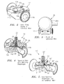
Figure 1 shows an isometric view cut along a weir centerline of a diaphragm valve having a typical weir shape that is known in the art. -
Figure 2 shows a valve body with a spherical weir according to some embodiments of the present invention. -
Figure 3 shows in combination a valve body and a polishing member, wherein the polish of the spherical weir is followed by a circular finish around the top rim (Both polish marks perpendicular to leak paths). -
Figure 4 shows part of a diaphragm valve having a spherical weir with a matching diaphragm, according to some embodiments of the present invention. -
Figure 5 shows part of a diaphragm valve having a spherical weir with a non-spherical diaphragm, according to some embodiments of the present invention. - In the following description of the exemplary embodiment, reference is made to the accompanying Figures in the drawing, which form a part hereof, and in which are shown by way of illustration of an embodiment in which the invention may be practiced. It is to be understood that other embodiments may be utilized, as structural and operational changes may be made without departing from the scope of the present invention.
-
Figures 2-5 show the present invention in the form of apparatus generally indicated as 10, 10', including a weir-type diaphragm valve, that features avalve body 12 configured with at least one spherically-shaped valvebody sealing surface diaphragm 14 configured with at least onediaphragm sealing surface diaphragm sealing surface body sealing surface valve body 12 includesfluid flow channels Figure 2 ) for passing fluid through the weir-type valve 12. - Consistent with that shown in
Figures 2-4 , the present invention may be implemented so as to utilize a singlespherical cap 14 to define the entire sealing surface of thevalve body 12. This eliminates corners and transitions in thediaphragm 14 in the sealing area of thevalve 12. The diaphragm shape away from thespherical weir 12a may, but does not need to, conform to the spherical shape of thevalve body 12. - In
Figures 2-5 , thevalve body 12 may be configured with aspherical weir 12a having a spherically-shapedweir sealing surface 12b as the at least one spherically-shaped valve body sealing surface. By way of example, the spherically-shapedweir sealing surface 12b may be configured with polish marks substantially perpendicular to a weir leak path, which is understood to be paths in the direction of the fluid flow through the valve body, e.g., from thefluid flow channel 11a tofluid flow channel 11b. Thediaphragm 14 may be configured with a diaphragmweir sealing surface 14a as the at least one diaphragm sealing surface. In operation, thediaphragm 14 may also configured to respond to the applied force and provide the sealing contact between the diaphragmweir sealing surface 14a and the spherically-shapedweir sealing surface 12b so as to stop the flow of fluid through thefluid flow channel valve body 12. - The
valve body 12 may also be configured with a circular orperipheral rim 12c having a spherically-shapedperipheral sealing surface 12d as the at least one spherically-shaped valve body sealing surface. By way of example, the spherically-shapedperipheral sealing surface 12d may be configured with polish marks, many of which are substantially perpendicular to a shell leak path, which is understood to be the radial leak path through the spherically-shapedperipheral sealing surface 12d. The diaphragm may be configured with a diaphragm peripheral sealingsurface 14b as the at least one diaphragm sealing surface. In operation, thediaphragm 14 may also configured to respond to the applied force and provide the sealing contact between the diaphragm peripheral sealingsurface 14b and the spherically-shapedperipheral sealing surface 12d so as to prevent the leaking of the fluid from the valve body via the shell leak path. - Consistent with that shown in
Figure 3 , the polish marks may be formed by a spherically-shaped polishing tool generally indicated as 30 having a polishingmember 30a. The polishing member is understood to have a radius R that defines the spherical polishing surface. - Consistent with that shown in
Figure 4 , thediaphragm 14 may be configured with at least a partially spherical shape. For example, the diaphragmweir sealing surface 14a may be configured with a spherical shape to match substantially the spherically-shapedweir sealing surface 12b, and/or the diaphragm peripheral sealingsurface 14b may be configured with a corresponding spherical shape to match substantially the spherically-shapedperipheral sealing surface 12d. The spherically- shapes conformity of theweir sealing surfaces diaphragm sealing surfaces corresponding sealing surfaces - Consistent with that shown in
Figure 4 , theapparatus 10 may also include abacking cushion 16, adiaphragm stud 18, acompressor 20, and aspindle 22. - The scope of the invention is intended to include embodiments wherein the
backing cushion 16 may be configured with a corresponding spherical shape to match substantially the spherical shape of the diaphragmweir sealing surface 14a, as shown inFigure 4 . - The scope of the invention is also intended to include embodiments wherein the
compressor 20 may be configured with at least a partially spherical shape to match substantially the diaphragmweir sealing surface 14a. - The scope of the invention is also intended to include embodiments wherein the
diaphragm 14 may be configured with at least a partially spherical shape, and the diaphragmweir sealing surface 14a may have a spherical shape to match substantially the spherically-shapedweir sealing surface 12b. - In
Figure 4 , thevalve body 12 is also shown having shouldered pins, one of which is identified withreference label 25, that cooperate with keyways (not shown) for rotationally coupling thevalve body 12 and a bonnet portion (not shown), consistent with that disclosed in patent application serial no.13/554,532, filed 20 July 2012 - Consistent with that shown in
Figure 5 , the weir-type diaphragm valve 10' has the diaphragm 14' which may be configured with a non-spherical shape, including being a substantially flat shape. Since the diaphragm 14' is made of an elastomeric material, such as PTFE, in operation it will to respond to the applied force, suitable stretch and provide the sealing contact between the at least onediaphragm sealing surface body sealing surface Figure 4 . - In
Figure 5 , components and parts of the weir-type diaphragm valve 10' that correspond to similar components and parts as the weir-type diaphragm valve 10 inFigures 2-4 are labeled with similar reference numerals or labeled with similar reference numerals having an accent "' ", including a backing cushion 16', a compressor 20' and a spindle 22'. In addition, the weir-type diaphragm valve 10' also includes studs , one of which is shown and identified withreference label 19 that is coupled between the diaphragm 14' and compressor 20' and arranged on each side of thespherical weir 12a for sealing the diaphragmweir sealing surface 14a and the spherically-shapedweir sealing surface 12b so as to stop the flow of fluid through thefluid flow channel valve body 12, consistent with that disclosed in patent application serial no.13/554,535, filed 20 July 2012 13/554,541, filed 20 July 2012 - By way of example, the
diaphragm 14 may be made of, or configured from, Polytetrafluoroethylene (PTFE), which is a synthetic fluoropolymer of tetrafluoroethylene that is known in the art, although the scope of the invention is intended to include the diaphragm being made from other types or kinds of materials either now known or later developed in the future. - A person skilled in the art would understand and appreciate that a sphere is a perfectly round geometrical object in three-dimensional space, such as the shape of a round ball. Like a circle, which is in two dimensions, a sphere is the set of points which are all the same distance r from a given point in space. This distance r is known as the "radius" of the sphere, and the given point is known as the center of the sphere. The maximum straight distance through the sphere is known as the "diameter". It passes through the center and is thus twice the radius.
- The spherically-shaped
weir sealing surface 12b and the spherically-shapedperipheral sealing surface 12d are understood to be configured on, or formed part of, thevalve body 12 having respective spherical shapes in three dimensions, consistent with this appreciate of what a sphere is understood to be. - Moreover, consistent with that shown in
Figure 4 , for embodiments in which thediaphragm 14 are configured with at least a partially spherical shape, the spherically-shaped diaphragmweir sealing surface 14a and the spherically-shaped diaphragm peripheral sealingsurface 14b are understood to have respective spherical shapes in three dimensions, also consistent with this appreciate of what a sphere is understood to be. - According to some embodiments, the spherically-shaped
weir sealing surface 12b and the spherically-shapedperipheral sealing surface 12d may each have a respective radius of curvature that are substantially equal. The respective radius of curvature may correspond to the radius R that defines the spherical polishing surface of the polishingmember 30a inFigure 3 . - However, the scope of the invention is not intended to be limited to any particular relationship between the respective radius of curvature of the spherically-shaped
weir sealing surface 12b and the spherically-shapedperipheral sealing surface 12d. - For example, alternatively the scope of the invention is intended to include embodiments where the spherically-shaped
weir sealing surface 12b and the spherically-shapedperipheral sealing surface 12d may each have a respective radius of curvature that are different. For example, the spherically-shapedweir sealing surface 12b may have a first radius of curvature that corresponds to a first radius of a first spherically-shaped polishing tool like the tool shown inFigure 3 used to form the spherically-shapedweir sealing surface 12b, while the spherically-shapedperipheral sealing surface 12d may have a second radius of curvature that corresponds to a second radius of a second and different spherically-shaped polishing tool than that used inFigure 3 to form the spherically-shapedperipheral sealing surface 12b. - Further, by way of example, the first radius of curvature may be greater than the second radius of curvature; or the first radius of curvature may be less than the second radius of curvature.
- A person skilled in the art would understand that, in geometry, the radius of curvature, R, of a curve at a point is a measure of the radius of the circular arc which best approximates the curve at that point.
- It should be understood that, unless stated otherwise herein, any of the features, characteristics, alternatives or modifications described regarding a particular embodiment herein may also be applied, used, or incorporated with any other embodiment described herein. Also, the drawings herein are not drawn to scale.
- Although the invention has been described and illustrated with respect to exemplary embodiments thereof, the foregoing and various other additions and omissions may be made therein and thereto without departing from the spirit and scope of the present invention.
Claims (19)
- Apparatus, including a weir-type diaphragm valve, comprising:a valve body configured with at least one spherically-shaped valve body sealing surface; anda diaphragm configured with at least one diaphragm sealing surface, and also configured to respond to an applied force and provide sealing contact between the at least one diaphragm sealing surface and the at least one spherically-shaped valve body sealing surface.
- Apparatus according to claim 1, wherein the valve body is configured with a spherical weir having a spherically-shaped weir sealing surface as the at least one spherically-shaped valve body sealing surface.
- Apparatus according to claim 2, wherein the spherically-shaped weir sealing surface is configured with polish marks substantially perpendicular to a weir leak path.
- Apparatus according to claim 1, wherein the valve body is configured with a circular rim having a spherically-shaped peripheral sealing surface as the at least one spherically-shaped valve body sealing surface.
- Apparatus according to claim 4, wherein the spherically-shaped peripheral sealing surface is configured with polish marks, many of which are substantially perpendicular to a shell leak path.
- Apparatus according to claim 1, wherein
the valve body is configured with a spherical weir having a spherically-shaped weir sealing surface as the at least one spherically-shaped valve body sealing surface, and the diaphragm is configured with a diaphragm weir sealing surface as the at least one diaphragm sealing surface, and
the diaphragm is also configured to respond to the applied force and provide the sealing contact between the diaphragm weir sealing surface and the spherically-shaped weir sealing surface so as to stop the flow of fluid through a fluid flow channel of the valve body. - Apparatus according to claim 1 or 6, wherein the diaphragm is configured with at least a partially spherical shape, and the diaphragm weir sealing surface has a spherical shape to match substantially the spherically-shaped weir sealing surface.
- Apparatus according to claim 6, wherein the diaphragm is configured with a non-spherical shape, including a substantially flat shape.
- Apparatus according to claim 6, wherein the spherically-shaped weir sealing surface is configured with polish marks substantially perpendicular to a weir leak path, including being perpendicular to the flow of fluid through the fluid flow channel of the valve body.
- Apparatus according to claim 9, wherein the polish marks are formed by a spherically-shaped polishing tool.
- Apparatus according to claim 1 or 6, wherein
the valve body is configured with a circular rim having a spherically-shaped peripheral sealing surface as the at least one spherically-shaped valve body sealing surface, and the diaphragm is configured with a diaphragm peripheral sealing surface as the at least one diaphragm sealing surface, and
the diaphragm is also configured to respond to the applied force and provide the sealing contact between the diaphragm peripheral sealing surface and the spherically-shaped peripheral sealing surface so as to prevent the leaking of the fluid from the valve body via a shell leak path. - Apparatus according to claim 6, wherein the spherically-shaped weir sealing surface and the spherically-shaped peripheral sealing surface each have a respective radius of curvature that are substantially equal.
- Apparatus according to claim 12, wherein the respective radius of curvature corresponds to a corresponding radius of a spherically-shaped polishing tool used to form the spherically-shaped weir sealing surface and the spherically-shaped peripheral sealing surface.
- Apparatus according to claim 6, wherein the spherically-shaped weir sealing surface and the spherically-shaped peripheral sealing surface each have a respective radius of curvature that are different.
- Apparatus according to claim 11, wherein the spherically-shaped weir sealing surface has a first radius of curvature that corresponds to a first radius of a first spherically-shaped polishing tool used to form the spherically-shaped weir sealing surface, and the spherically-shaped peripheral sealing surface has a second radius of curvature that corresponds to a second radius of a second spherically-shaped polishing tool used to form the spherically-shaped peripheral sealing surface.
- Apparatus according to claim 15, wherein the first radius of curvature is greater or less than the second radius of curvature.
- Apparatus according to claim 7, wherein the apparatus further comprises a backing cushion configured with a corresponding spherical shape to match substantially the spherical shape of the diaphragm weir sealing surface.
- Apparatus according to claim 17, wherein the apparatus further comprises a compressor configured with at least a partially spherical shape to match substantially the diaphragm weir sealing surface.
- Apparatus according to claim 7, wherein the apparatus further comprises a compressor configured with at least a partially spherical shape to match substantially the diaphragm weir sealing surface.
Applications Claiming Priority (1)
| Application Number | Priority Date | Filing Date | Title |
|---|---|---|---|
| US13/595,652 US9243718B2 (en) | 2012-08-27 | 2012-08-27 | Diaphragm valve having spherically-shaped valve body and diaphragm sealing surface |
Publications (2)
| Publication Number | Publication Date |
|---|---|
| EP2703700A1 true EP2703700A1 (en) | 2014-03-05 |
| EP2703700B1 EP2703700B1 (en) | 2016-03-02 |
Family
ID=48979589
Family Applications (1)
| Application Number | Title | Priority Date | Filing Date |
|---|---|---|---|
| EP13179972.8A Not-in-force EP2703700B1 (en) | 2012-08-27 | 2013-08-09 | Diaphragm valve having spherically-shaped valve body and diaphragm sealing surface |
Country Status (2)
| Country | Link |
|---|---|
| US (1) | US9243718B2 (en) |
| EP (1) | EP2703700B1 (en) |
Cited By (1)
| Publication number | Priority date | Publication date | Assignee | Title |
|---|---|---|---|---|
| DE102020100744A1 (en) * | 2020-01-14 | 2021-07-15 | Gemü Gebr. Müller Apparatebau Gmbh & Co. Kommanditgesellschaft | Valve body, diaphragm and diaphragm valve |
Citations (6)
| Publication number | Priority date | Publication date | Assignee | Title |
|---|---|---|---|---|
| BE551707A (en) * | ||||
| US1855991A (en) * | 1930-10-11 | 1932-04-26 | Saunders Inv S Ltd | Diaphragm valve |
| CH316891A (en) * | 1953-09-11 | 1956-10-31 | Alpura Ag | Diaphragm valve |
| US3310281A (en) | 1965-11-16 | 1967-03-21 | Grinnell Corp | Diaphragm valve |
| US3719343A (en) * | 1971-04-08 | 1973-03-06 | Ladish Co | Fluid pressure actuated diaphragm valve |
| US5632465A (en) * | 1990-10-29 | 1997-05-27 | Cordua; Paul M. | Valve assembly |
Family Cites Families (41)
| Publication number | Priority date | Publication date | Assignee | Title |
|---|---|---|---|---|
| US1800157A (en) * | 1929-02-14 | 1931-04-07 | Saunders Philip Keith | Diaphragm valve |
| US2716017A (en) | 1952-08-28 | 1955-08-23 | Grinnell Corp | Diaphragm valves |
| US3148861A (en) * | 1962-06-27 | 1964-09-15 | Hills Mccanna Co | Weir valve |
| US3275292A (en) | 1962-07-19 | 1966-09-27 | Grinnell Corp | Diaphragm valve body flange construction |
| BE647614A (en) | 1963-05-06 | |||
| US3349795A (en) | 1964-04-22 | 1967-10-31 | Ngk Insulators Ltd | Diaphragm valve including a snap ring connection |
| FR1411166A (en) * | 1964-07-29 | 1965-09-17 | Improvement in diaphragm valves | |
| US3374522A (en) | 1965-01-22 | 1968-03-26 | Grinnell Corp | Method of making diaphragm valve bodies |
| US3263875A (en) | 1965-07-26 | 1966-08-02 | Boise Cascade Corp | Disposable drip-free dispensing valve |
| US3310282A (en) | 1965-11-15 | 1967-03-21 | Grinnell Corp | Diaphragm control valves |
| US3310280A (en) * | 1965-11-16 | 1967-03-21 | Grinnell Corp | Diaphragm valve |
| US3479696A (en) | 1967-06-30 | 1969-11-25 | Grinnell Corp | Apparatus for molding liners in hollow metal bodies |
| US3628770A (en) * | 1970-05-04 | 1971-12-21 | Hills Mccanna Co | Diaphragm valve construction |
| US3874636A (en) * | 1973-11-19 | 1975-04-01 | Rockwell International Corp | Sealed valve and related structure |
| US4214604A (en) | 1978-02-06 | 1980-07-29 | Rumsey Rollin D | Straight through flow diaphragm valve structures |
| US4624442A (en) * | 1985-01-23 | 1986-11-25 | Duffy John W | Control regulator having a rolling diaphragm |
| US4836236A (en) | 1987-07-29 | 1989-06-06 | Ladisch Thomas P | Flush sealing tank valve with diaphgram |
| US4836719A (en) | 1987-12-28 | 1989-06-06 | Ford Motor Company | Method and apparatus for machining valve seats and valve stem guides in a deep-walled engine monoblock workpiece |
| DK247989D0 (en) * | 1989-05-22 | 1989-05-22 | Novo Nordisk As | CONE VALVE |
| US5123439A (en) | 1990-02-01 | 1992-06-23 | Industrial Ceramics Engineering | Valve body ceramic liners |
| US5127430A (en) | 1990-02-01 | 1992-07-07 | Industrial Ceramics Engineering | Ceramic weir for valve body |
| US5277401A (en) | 1991-04-17 | 1994-01-11 | Itt Corporation | Tank bottom diaphragm valve |
| DE19504120A1 (en) | 1995-02-08 | 1996-08-14 | Buerkert Werke Gmbh & Co | Method of manufacturing a valve housing |
| IL119963A (en) * | 1997-01-05 | 2003-02-12 | Raphael Valves Ind 1975 Ltd | Spring diaphragm for shut-off valves and regulators |
| US5755155A (en) | 1997-02-28 | 1998-05-26 | Tetra Laval Holdings & Finance S.A. | Aseptic process interface group |
| US6047953A (en) | 1999-04-27 | 2000-04-11 | Jacob, Jr.; Eugene W. | Diaphragm compression restrainer |
| US6575431B2 (en) | 1999-09-14 | 2003-06-10 | Spears Manufacturing Co. | Weir-type diaphragm valve with raised arcuate bead |
| US6416038B1 (en) * | 2000-08-17 | 2002-07-09 | Aseptic Controls Investment Co. | Inline process valve assembly |
| WO2002066876A1 (en) | 2001-02-20 | 2002-08-29 | Nl Technologies, Ltd. | Circumferential sealing diaphragm valve |
| US6789781B2 (en) | 2001-03-16 | 2004-09-14 | Entegris, Inc. | Reinforced diaphragm valve |
| EP1490613A4 (en) | 2002-03-18 | 2005-09-07 | Entegris Inc | Fully drainable weir valve |
| WO2005052419A1 (en) | 2003-11-04 | 2005-06-09 | Crane Process Flow Technologies Limited | Diaphragm valve |
| US7204474B2 (en) | 2004-08-06 | 2007-04-17 | Stinger Wellhead Protection, Inc. | High-pressure plug valve |
| US8146889B2 (en) | 2004-08-27 | 2012-04-03 | Vetco Gray Inc. | Low friction coatings for dynamically engaging load bearing surfaces |
| DE102005016600A1 (en) | 2005-04-11 | 2006-10-12 | GEMÜ Gebr. Müller Apparatebau GmbH & Co. KG | diaphragm valve |
| US7789012B2 (en) | 2005-04-25 | 2010-09-07 | Aquasyn, Llc | Valve bonnet assembly |
| US7926785B2 (en) | 2005-06-22 | 2011-04-19 | Wincek Christopher P | Valve diaphragm with a compression restraining ring, and valve including same |
| US20100140528A1 (en) | 2006-07-05 | 2010-06-10 | Mclennan William Ross | Valve construction |
| EP3217051B1 (en) * | 2006-10-20 | 2020-03-04 | Tyco Fire Products LP | System for fire protection |
| WO2009012479A1 (en) * | 2007-07-19 | 2009-01-22 | Swagelok Company | Coated seals |
| US7775234B2 (en) | 2008-01-23 | 2010-08-17 | Marc Wyler Campisi | Valve-to-fitting converter for process piping systems |
-
2012
- 2012-08-27 US US13/595,652 patent/US9243718B2/en not_active Expired - Fee Related
-
2013
- 2013-08-09 EP EP13179972.8A patent/EP2703700B1/en not_active Not-in-force
Patent Citations (6)
| Publication number | Priority date | Publication date | Assignee | Title |
|---|---|---|---|---|
| BE551707A (en) * | ||||
| US1855991A (en) * | 1930-10-11 | 1932-04-26 | Saunders Inv S Ltd | Diaphragm valve |
| CH316891A (en) * | 1953-09-11 | 1956-10-31 | Alpura Ag | Diaphragm valve |
| US3310281A (en) | 1965-11-16 | 1967-03-21 | Grinnell Corp | Diaphragm valve |
| US3719343A (en) * | 1971-04-08 | 1973-03-06 | Ladish Co | Fluid pressure actuated diaphragm valve |
| US5632465A (en) * | 1990-10-29 | 1997-05-27 | Cordua; Paul M. | Valve assembly |
Cited By (1)
| Publication number | Priority date | Publication date | Assignee | Title |
|---|---|---|---|---|
| DE102020100744A1 (en) * | 2020-01-14 | 2021-07-15 | Gemü Gebr. Müller Apparatebau Gmbh & Co. Kommanditgesellschaft | Valve body, diaphragm and diaphragm valve |
Also Published As
| Publication number | Publication date |
|---|---|
| EP2703700B1 (en) | 2016-03-02 |
| US20140054488A1 (en) | 2014-02-27 |
| US9243718B2 (en) | 2016-01-26 |
Similar Documents
| Publication | Publication Date | Title |
|---|---|---|
| CN104989839B (en) | Ball valve | |
| US9046180B2 (en) | Diaphragm and backing cushion shaping for increased membrane life | |
| KR101453475B1 (en) | Squeeze packing | |
| JP2011226647A (en) | Fluid valve control members having contoured sealing surfaces | |
| US9446485B2 (en) | Double offset ball member usable in ball valves and other flow control applications | |
| JP6995047B2 (en) | Diaphragm valves and flow control equipment for semiconductor manufacturing equipment | |
| US20160068235A1 (en) | Independent tank with curvature change section, and manufacturing method for independent tank | |
| CN110873192A (en) | Fluoroplastic butterfly valve structure | |
| US8628094B2 (en) | Metal seal | |
| EP2703700B1 (en) | Diaphragm valve having spherically-shaped valve body and diaphragm sealing surface | |
| EP4085208B1 (en) | Design for a seat insert in a ball valve for cryogenic applications | |
| CN102695901A (en) | Valve and sealing ring | |
| KR20130040852A (en) | Valve element of butterfly valve | |
| US20160238142A1 (en) | Valve member for a floating ball valve | |
| JP2010101357A (en) | Diaphragm valve device | |
| JP2020159518A (en) | Butterfly valve | |
| JP2020153393A (en) | Manufacturing method of diaphragm unit, diaphragm valve, and diaphragm unit | |
| JP2017129249A (en) | valve | |
| JPWO2019151500A1 (en) | Diaphragm valve |
Legal Events
| Date | Code | Title | Description |
|---|---|---|---|
| AK | Designated contracting states |
Kind code of ref document: A1 Designated state(s): AL AT BE BG CH CY CZ DE DK EE ES FI FR GB GR HR HU IE IS IT LI LT LU LV MC MK MT NL NO PL PT RO RS SE SI SK SM TR |
|
| AX | Request for extension of the european patent |
Extension state: BA ME |
|
| PUAI | Public reference made under article 153(3) epc to a published international application that has entered the european phase |
Free format text: ORIGINAL CODE: 0009012 |
|
| 17P | Request for examination filed |
Effective date: 20140905 |
|
| RBV | Designated contracting states (corrected) |
Designated state(s): AL AT BE BG CH CY CZ DE DK EE ES FI FR GB GR HR HU IE IS IT LI LT LU LV MC MK MT NL NO PL PT RO RS SE SI SK SM TR |
|
| 17Q | First examination report despatched |
Effective date: 20150128 |
|
| GRAP | Despatch of communication of intention to grant a patent |
Free format text: ORIGINAL CODE: EPIDOSNIGR1 |
|
| INTG | Intention to grant announced |
Effective date: 20150917 |
|
| GRAS | Grant fee paid |
Free format text: ORIGINAL CODE: EPIDOSNIGR3 |
|
| GRAA | (expected) grant |
Free format text: ORIGINAL CODE: 0009210 |
|
| AK | Designated contracting states |
Kind code of ref document: B1 Designated state(s): AL AT BE BG CH CY CZ DE DK EE ES FI FR GB GR HR HU IE IS IT LI LT LU LV MC MK MT NL NO PL PT RO RS SE SI SK SM TR |
|
| REG | Reference to a national code |
Ref country code: GB Ref legal event code: FG4D |
|
| REG | Reference to a national code |
Ref country code: AT Ref legal event code: REF Ref document number: 778294 Country of ref document: AT Kind code of ref document: T Effective date: 20160315 Ref country code: CH Ref legal event code: EP |
|
| REG | Reference to a national code |
Ref country code: IE Ref legal event code: FG4D |
|
| REG | Reference to a national code |
Ref country code: DE Ref legal event code: R096 Ref document number: 602013005218 Country of ref document: DE |
|
| REG | Reference to a national code |
Ref country code: NL Ref legal event code: MP Effective date: 20160302 |
|
| REG | Reference to a national code |
Ref country code: LT Ref legal event code: MG4D |
|
| REG | Reference to a national code |
Ref country code: AT Ref legal event code: MK05 Ref document number: 778294 Country of ref document: AT Kind code of ref document: T Effective date: 20160302 |
|
| PG25 | Lapsed in a contracting state [announced via postgrant information from national office to epo] |
Ref country code: HR Free format text: LAPSE BECAUSE OF FAILURE TO SUBMIT A TRANSLATION OF THE DESCRIPTION OR TO PAY THE FEE WITHIN THE PRESCRIBED TIME-LIMIT Effective date: 20160302 Ref country code: FI Free format text: LAPSE BECAUSE OF FAILURE TO SUBMIT A TRANSLATION OF THE DESCRIPTION OR TO PAY THE FEE WITHIN THE PRESCRIBED TIME-LIMIT Effective date: 20160302 Ref country code: NO Free format text: LAPSE BECAUSE OF FAILURE TO SUBMIT A TRANSLATION OF THE DESCRIPTION OR TO PAY THE FEE WITHIN THE PRESCRIBED TIME-LIMIT Effective date: 20160602 Ref country code: GR Free format text: LAPSE BECAUSE OF FAILURE TO SUBMIT A TRANSLATION OF THE DESCRIPTION OR TO PAY THE FEE WITHIN THE PRESCRIBED TIME-LIMIT Effective date: 20160603 Ref country code: ES Free format text: LAPSE BECAUSE OF FAILURE TO SUBMIT A TRANSLATION OF THE DESCRIPTION OR TO PAY THE FEE WITHIN THE PRESCRIBED TIME-LIMIT Effective date: 20160302 |
|
| REG | Reference to a national code |
Ref country code: FR Ref legal event code: PLFP Year of fee payment: 4 |
|
| PG25 | Lapsed in a contracting state [announced via postgrant information from national office to epo] |
Ref country code: SE Free format text: LAPSE BECAUSE OF FAILURE TO SUBMIT A TRANSLATION OF THE DESCRIPTION OR TO PAY THE FEE WITHIN THE PRESCRIBED TIME-LIMIT Effective date: 20160302 Ref country code: PL Free format text: LAPSE BECAUSE OF FAILURE TO SUBMIT A TRANSLATION OF THE DESCRIPTION OR TO PAY THE FEE WITHIN THE PRESCRIBED TIME-LIMIT Effective date: 20160302 Ref country code: LT Free format text: LAPSE BECAUSE OF FAILURE TO SUBMIT A TRANSLATION OF THE DESCRIPTION OR TO PAY THE FEE WITHIN THE PRESCRIBED TIME-LIMIT Effective date: 20160302 Ref country code: AT Free format text: LAPSE BECAUSE OF FAILURE TO SUBMIT A TRANSLATION OF THE DESCRIPTION OR TO PAY THE FEE WITHIN THE PRESCRIBED TIME-LIMIT Effective date: 20160302 Ref country code: NL Free format text: LAPSE BECAUSE OF FAILURE TO SUBMIT A TRANSLATION OF THE DESCRIPTION OR TO PAY THE FEE WITHIN THE PRESCRIBED TIME-LIMIT Effective date: 20160302 Ref country code: RS Free format text: LAPSE BECAUSE OF FAILURE TO SUBMIT A TRANSLATION OF THE DESCRIPTION OR TO PAY THE FEE WITHIN THE PRESCRIBED TIME-LIMIT Effective date: 20160302 Ref country code: LV Free format text: LAPSE BECAUSE OF FAILURE TO SUBMIT A TRANSLATION OF THE DESCRIPTION OR TO PAY THE FEE WITHIN THE PRESCRIBED TIME-LIMIT Effective date: 20160302 |
|
| PG25 | Lapsed in a contracting state [announced via postgrant information from national office to epo] |
Ref country code: IS Free format text: LAPSE BECAUSE OF FAILURE TO SUBMIT A TRANSLATION OF THE DESCRIPTION OR TO PAY THE FEE WITHIN THE PRESCRIBED TIME-LIMIT Effective date: 20160702 Ref country code: EE Free format text: LAPSE BECAUSE OF FAILURE TO SUBMIT A TRANSLATION OF THE DESCRIPTION OR TO PAY THE FEE WITHIN THE PRESCRIBED TIME-LIMIT Effective date: 20160302 |
|
| PG25 | Lapsed in a contracting state [announced via postgrant information from national office to epo] |
Ref country code: RO Free format text: LAPSE BECAUSE OF FAILURE TO SUBMIT A TRANSLATION OF THE DESCRIPTION OR TO PAY THE FEE WITHIN THE PRESCRIBED TIME-LIMIT Effective date: 20160302 Ref country code: SM Free format text: LAPSE BECAUSE OF FAILURE TO SUBMIT A TRANSLATION OF THE DESCRIPTION OR TO PAY THE FEE WITHIN THE PRESCRIBED TIME-LIMIT Effective date: 20160302 Ref country code: PT Free format text: LAPSE BECAUSE OF FAILURE TO SUBMIT A TRANSLATION OF THE DESCRIPTION OR TO PAY THE FEE WITHIN THE PRESCRIBED TIME-LIMIT Effective date: 20160704 Ref country code: CZ Free format text: LAPSE BECAUSE OF FAILURE TO SUBMIT A TRANSLATION OF THE DESCRIPTION OR TO PAY THE FEE WITHIN THE PRESCRIBED TIME-LIMIT Effective date: 20160302 Ref country code: SK Free format text: LAPSE BECAUSE OF FAILURE TO SUBMIT A TRANSLATION OF THE DESCRIPTION OR TO PAY THE FEE WITHIN THE PRESCRIBED TIME-LIMIT Effective date: 20160302 |
|
| REG | Reference to a national code |
Ref country code: DE Ref legal event code: R097 Ref document number: 602013005218 Country of ref document: DE |
|
| PG25 | Lapsed in a contracting state [announced via postgrant information from national office to epo] |
Ref country code: IT Free format text: LAPSE BECAUSE OF FAILURE TO SUBMIT A TRANSLATION OF THE DESCRIPTION OR TO PAY THE FEE WITHIN THE PRESCRIBED TIME-LIMIT Effective date: 20160302 Ref country code: BE Free format text: LAPSE BECAUSE OF FAILURE TO SUBMIT A TRANSLATION OF THE DESCRIPTION OR TO PAY THE FEE WITHIN THE PRESCRIBED TIME-LIMIT Effective date: 20160302 |
|
| PLBE | No opposition filed within time limit |
Free format text: ORIGINAL CODE: 0009261 |
|
| STAA | Information on the status of an ep patent application or granted ep patent |
Free format text: STATUS: NO OPPOSITION FILED WITHIN TIME LIMIT |
|
| PG25 | Lapsed in a contracting state [announced via postgrant information from national office to epo] |
Ref country code: DK Free format text: LAPSE BECAUSE OF FAILURE TO SUBMIT A TRANSLATION OF THE DESCRIPTION OR TO PAY THE FEE WITHIN THE PRESCRIBED TIME-LIMIT Effective date: 20160302 |
|
| 26N | No opposition filed |
Effective date: 20161205 |
|
| PG25 | Lapsed in a contracting state [announced via postgrant information from national office to epo] |
Ref country code: SI Free format text: LAPSE BECAUSE OF FAILURE TO SUBMIT A TRANSLATION OF THE DESCRIPTION OR TO PAY THE FEE WITHIN THE PRESCRIBED TIME-LIMIT Effective date: 20160302 Ref country code: BG Free format text: LAPSE BECAUSE OF FAILURE TO SUBMIT A TRANSLATION OF THE DESCRIPTION OR TO PAY THE FEE WITHIN THE PRESCRIBED TIME-LIMIT Effective date: 20160602 |
|
| PG25 | Lapsed in a contracting state [announced via postgrant information from national office to epo] |
Ref country code: MC Free format text: LAPSE BECAUSE OF FAILURE TO SUBMIT A TRANSLATION OF THE DESCRIPTION OR TO PAY THE FEE WITHIN THE PRESCRIBED TIME-LIMIT Effective date: 20160302 |
|
| REG | Reference to a national code |
Ref country code: CH Ref legal event code: PL |
|
| PG25 | Lapsed in a contracting state [announced via postgrant information from national office to epo] |
Ref country code: CH Free format text: LAPSE BECAUSE OF NON-PAYMENT OF DUE FEES Effective date: 20160831 Ref country code: LI Free format text: LAPSE BECAUSE OF NON-PAYMENT OF DUE FEES Effective date: 20160831 |
|
| REG | Reference to a national code |
Ref country code: FR Ref legal event code: PLFP Year of fee payment: 5 |
|
| PG25 | Lapsed in a contracting state [announced via postgrant information from national office to epo] |
Ref country code: LU Free format text: LAPSE BECAUSE OF NON-PAYMENT OF DUE FEES Effective date: 20160809 |
|
| PG25 | Lapsed in a contracting state [announced via postgrant information from national office to epo] |
Ref country code: CY Free format text: LAPSE BECAUSE OF FAILURE TO SUBMIT A TRANSLATION OF THE DESCRIPTION OR TO PAY THE FEE WITHIN THE PRESCRIBED TIME-LIMIT Effective date: 20160302 Ref country code: HU Free format text: LAPSE BECAUSE OF FAILURE TO SUBMIT A TRANSLATION OF THE DESCRIPTION OR TO PAY THE FEE WITHIN THE PRESCRIBED TIME-LIMIT; INVALID AB INITIO Effective date: 20130809 |
|
| PG25 | Lapsed in a contracting state [announced via postgrant information from national office to epo] |
Ref country code: MT Free format text: LAPSE BECAUSE OF NON-PAYMENT OF DUE FEES Effective date: 20160831 Ref country code: MK Free format text: LAPSE BECAUSE OF FAILURE TO SUBMIT A TRANSLATION OF THE DESCRIPTION OR TO PAY THE FEE WITHIN THE PRESCRIBED TIME-LIMIT Effective date: 20160302 Ref country code: TR Free format text: LAPSE BECAUSE OF FAILURE TO SUBMIT A TRANSLATION OF THE DESCRIPTION OR TO PAY THE FEE WITHIN THE PRESCRIBED TIME-LIMIT Effective date: 20160302 |
|
| REG | Reference to a national code |
Ref country code: FR Ref legal event code: PLFP Year of fee payment: 6 |
|
| PG25 | Lapsed in a contracting state [announced via postgrant information from national office to epo] |
Ref country code: AL Free format text: LAPSE BECAUSE OF FAILURE TO SUBMIT A TRANSLATION OF THE DESCRIPTION OR TO PAY THE FEE WITHIN THE PRESCRIBED TIME-LIMIT Effective date: 20160302 |
|
| PGFP | Annual fee paid to national office [announced via postgrant information from national office to epo] |
Ref country code: IE Payment date: 20190827 Year of fee payment: 7 Ref country code: DE Payment date: 20190828 Year of fee payment: 7 Ref country code: FR Payment date: 20190826 Year of fee payment: 7 |
|
| PGFP | Annual fee paid to national office [announced via postgrant information from national office to epo] |
Ref country code: GB Payment date: 20190827 Year of fee payment: 7 |
|
| REG | Reference to a national code |
Ref country code: DE Ref legal event code: R119 Ref document number: 602013005218 Country of ref document: DE |
|
| GBPC | Gb: european patent ceased through non-payment of renewal fee |
Effective date: 20200809 |
|
| PG25 | Lapsed in a contracting state [announced via postgrant information from national office to epo] |
Ref country code: FR Free format text: LAPSE BECAUSE OF NON-PAYMENT OF DUE FEES Effective date: 20200831 Ref country code: DE Free format text: LAPSE BECAUSE OF NON-PAYMENT OF DUE FEES Effective date: 20210302 |
|
| PG25 | Lapsed in a contracting state [announced via postgrant information from national office to epo] |
Ref country code: IE Free format text: LAPSE BECAUSE OF NON-PAYMENT OF DUE FEES Effective date: 20200809 Ref country code: GB Free format text: LAPSE BECAUSE OF NON-PAYMENT OF DUE FEES Effective date: 20200809 |