EP2703643A1 - Wind power generation system, device using wind power generation system, and method for operating same - Google Patents
Wind power generation system, device using wind power generation system, and method for operating same Download PDFInfo
- Publication number
- EP2703643A1 EP2703643A1 EP11864572.0A EP11864572A EP2703643A1 EP 2703643 A1 EP2703643 A1 EP 2703643A1 EP 11864572 A EP11864572 A EP 11864572A EP 2703643 A1 EP2703643 A1 EP 2703643A1
- Authority
- EP
- European Patent Office
- Prior art keywords
- wind
- wind turbine
- power
- power generation
- generation system
- Prior art date
- Legal status (The legal status is an assumption and is not a legal conclusion. Google has not performed a legal analysis and makes no representation as to the accuracy of the status listed.)
- Granted
Links
Images






Classifications
-
- F—MECHANICAL ENGINEERING; LIGHTING; HEATING; WEAPONS; BLASTING
- F03—MACHINES OR ENGINES FOR LIQUIDS; WIND, SPRING, OR WEIGHT MOTORS; PRODUCING MECHANICAL POWER OR A REACTIVE PROPULSIVE THRUST, NOT OTHERWISE PROVIDED FOR
- F03D—WIND MOTORS
- F03D7/00—Controlling wind motors
- F03D7/02—Controlling wind motors the wind motors having rotation axis substantially parallel to the air flow entering the rotor
- F03D7/04—Automatic control; Regulation
-
- H—ELECTRICITY
- H02—GENERATION; CONVERSION OR DISTRIBUTION OF ELECTRIC POWER
- H02J—ELECTRIC POWER NETWORKS; CIRCUIT ARRANGEMENTS OR SYSTEMS FOR SUPPLYING OR DISTRIBUTING ELECTRIC POWER; SYSTEMS FOR STORING ELECTRIC ENERGY
- H02J11/00—Circuit arrangements for providing service supply to auxiliaries of stations in which electric power is generated, distributed or converted
-
- F—MECHANICAL ENGINEERING; LIGHTING; HEATING; WEAPONS; BLASTING
- F03—MACHINES OR ENGINES FOR LIQUIDS; WIND, SPRING, OR WEIGHT MOTORS; PRODUCING MECHANICAL POWER OR A REACTIVE PROPULSIVE THRUST, NOT OTHERWISE PROVIDED FOR
- F03D—WIND MOTORS
- F03D1/00—Wind motors with rotation axis substantially parallel to the air flow entering the rotor
- F03D1/02—Wind motors with rotation axis substantially parallel to the air flow entering the rotor having a plurality of rotors
-
- F—MECHANICAL ENGINEERING; LIGHTING; HEATING; WEAPONS; BLASTING
- F03—MACHINES OR ENGINES FOR LIQUIDS; WIND, SPRING, OR WEIGHT MOTORS; PRODUCING MECHANICAL POWER OR A REACTIVE PROPULSIVE THRUST, NOT OTHERWISE PROVIDED FOR
- F03D—WIND MOTORS
- F03D7/00—Controlling wind motors
- F03D7/02—Controlling wind motors the wind motors having rotation axis substantially parallel to the air flow entering the rotor
- F03D7/026—Controlling wind motors the wind motors having rotation axis substantially parallel to the air flow entering the rotor for starting-up
-
- F—MECHANICAL ENGINEERING; LIGHTING; HEATING; WEAPONS; BLASTING
- F03—MACHINES OR ENGINES FOR LIQUIDS; WIND, SPRING, OR WEIGHT MOTORS; PRODUCING MECHANICAL POWER OR A REACTIVE PROPULSIVE THRUST, NOT OTHERWISE PROVIDED FOR
- F03D—WIND MOTORS
- F03D9/00—Adaptations of wind motors for special use; Combinations of wind motors with apparatus driven thereby; Wind motors specially adapted for installation in particular locations
-
- F—MECHANICAL ENGINEERING; LIGHTING; HEATING; WEAPONS; BLASTING
- F03—MACHINES OR ENGINES FOR LIQUIDS; WIND, SPRING, OR WEIGHT MOTORS; PRODUCING MECHANICAL POWER OR A REACTIVE PROPULSIVE THRUST, NOT OTHERWISE PROVIDED FOR
- F03D—WIND MOTORS
- F03D9/00—Adaptations of wind motors for special use; Combinations of wind motors with apparatus driven thereby; Wind motors specially adapted for installation in particular locations
- F03D9/007—Adaptations of wind motors for special use; Combinations of wind motors with apparatus driven thereby; Wind motors specially adapted for installation in particular locations the wind motor being combined with means for converting solar radiation into useful energy
-
- F—MECHANICAL ENGINEERING; LIGHTING; HEATING; WEAPONS; BLASTING
- F03—MACHINES OR ENGINES FOR LIQUIDS; WIND, SPRING, OR WEIGHT MOTORS; PRODUCING MECHANICAL POWER OR A REACTIVE PROPULSIVE THRUST, NOT OTHERWISE PROVIDED FOR
- F03D—WIND MOTORS
- F03D9/00—Adaptations of wind motors for special use; Combinations of wind motors with apparatus driven thereby; Wind motors specially adapted for installation in particular locations
- F03D9/10—Combinations of wind motors with apparatus storing energy
- F03D9/11—Combinations of wind motors with apparatus storing energy storing electrical energy
-
- F—MECHANICAL ENGINEERING; LIGHTING; HEATING; WEAPONS; BLASTING
- F03—MACHINES OR ENGINES FOR LIQUIDS; WIND, SPRING, OR WEIGHT MOTORS; PRODUCING MECHANICAL POWER OR A REACTIVE PROPULSIVE THRUST, NOT OTHERWISE PROVIDED FOR
- F03D—WIND MOTORS
- F03D9/00—Adaptations of wind motors for special use; Combinations of wind motors with apparatus driven thereby; Wind motors specially adapted for installation in particular locations
- F03D9/20—Wind motors characterised by the driven apparatus
- F03D9/25—Wind motors characterised by the driven apparatus the apparatus being an electrical generator
-
- F—MECHANICAL ENGINEERING; LIGHTING; HEATING; WEAPONS; BLASTING
- F03—MACHINES OR ENGINES FOR LIQUIDS; WIND, SPRING, OR WEIGHT MOTORS; PRODUCING MECHANICAL POWER OR A REACTIVE PROPULSIVE THRUST, NOT OTHERWISE PROVIDED FOR
- F03D—WIND MOTORS
- F03D9/00—Adaptations of wind motors for special use; Combinations of wind motors with apparatus driven thereby; Wind motors specially adapted for installation in particular locations
- F03D9/20—Wind motors characterised by the driven apparatus
- F03D9/25—Wind motors characterised by the driven apparatus the apparatus being an electrical generator
- F03D9/255—Wind motors characterised by the driven apparatus the apparatus being an electrical generator connected to electrical distribution networks; Arrangements therefor
-
- H—ELECTRICITY
- H02—GENERATION; CONVERSION OR DISTRIBUTION OF ELECTRIC POWER
- H02P—CONTROL OR REGULATION OF ELECTRIC MOTORS, ELECTRIC GENERATORS OR DYNAMO-ELECTRIC CONVERTERS; CONTROLLING TRANSFORMERS, REACTORS OR CHOKE COILS
- H02P9/00—Arrangements for controlling electric generators for the purpose of obtaining a desired output
- H02P9/04—Control effected upon non-electric prime mover and dependent upon electric output value of the generator
-
- F—MECHANICAL ENGINEERING; LIGHTING; HEATING; WEAPONS; BLASTING
- F05—INDEXING SCHEMES RELATING TO ENGINES OR PUMPS IN VARIOUS SUBCLASSES OF CLASSES F01-F04
- F05B—INDEXING SCHEME RELATING TO WIND, SPRING, WEIGHT, INERTIA OR LIKE MOTORS, TO MACHINES OR ENGINES FOR LIQUIDS COVERED BY SUBCLASSES F03B, F03D AND F03G
- F05B2220/00—Application
- F05B2220/70—Application in combination with
- F05B2220/706—Application in combination with an electrical generator
- F05B2220/7068—Application in combination with an electrical generator equipped with permanent magnets
-
- F—MECHANICAL ENGINEERING; LIGHTING; HEATING; WEAPONS; BLASTING
- F05—INDEXING SCHEMES RELATING TO ENGINES OR PUMPS IN VARIOUS SUBCLASSES OF CLASSES F01-F04
- F05B—INDEXING SCHEME RELATING TO WIND, SPRING, WEIGHT, INERTIA OR LIKE MOTORS, TO MACHINES OR ENGINES FOR LIQUIDS COVERED BY SUBCLASSES F03B, F03D AND F03G
- F05B2240/00—Components
- F05B2240/20—Rotors
- F05B2240/21—Rotors for wind turbines
- F05B2240/221—Rotors for wind turbines with horizontal axis
- F05B2240/2213—Rotors for wind turbines with horizontal axis and with the rotor downwind from the yaw pivot axis
-
- F—MECHANICAL ENGINEERING; LIGHTING; HEATING; WEAPONS; BLASTING
- F05—INDEXING SCHEMES RELATING TO ENGINES OR PUMPS IN VARIOUS SUBCLASSES OF CLASSES F01-F04
- F05B—INDEXING SCHEME RELATING TO WIND, SPRING, WEIGHT, INERTIA OR LIKE MOTORS, TO MACHINES OR ENGINES FOR LIQUIDS COVERED BY SUBCLASSES F03B, F03D AND F03G
- F05B2260/00—Function
- F05B2260/70—Adjusting of angle of incidence or attack of rotating blades
- F05B2260/76—Adjusting of angle of incidence or attack of rotating blades the adjusting mechanism using auxiliary power sources
-
- F—MECHANICAL ENGINEERING; LIGHTING; HEATING; WEAPONS; BLASTING
- F05—INDEXING SCHEMES RELATING TO ENGINES OR PUMPS IN VARIOUS SUBCLASSES OF CLASSES F01-F04
- F05B—INDEXING SCHEME RELATING TO WIND, SPRING, WEIGHT, INERTIA OR LIKE MOTORS, TO MACHINES OR ENGINES FOR LIQUIDS COVERED BY SUBCLASSES F03B, F03D AND F03G
- F05B2260/00—Function
- F05B2260/85—Starting
-
- Y—GENERAL TAGGING OF NEW TECHNOLOGICAL DEVELOPMENTS; GENERAL TAGGING OF CROSS-SECTIONAL TECHNOLOGIES SPANNING OVER SEVERAL SECTIONS OF THE IPC; TECHNICAL SUBJECTS COVERED BY FORMER USPC CROSS-REFERENCE ART COLLECTIONS [XRACs] AND DIGESTS
- Y02—TECHNOLOGIES OR APPLICATIONS FOR MITIGATION OR ADAPTATION AGAINST CLIMATE CHANGE
- Y02E—REDUCTION OF GREENHOUSE GAS [GHG] EMISSIONS, RELATED TO ENERGY GENERATION, TRANSMISSION OR DISTRIBUTION
- Y02E10/00—Energy generation through renewable energy sources
- Y02E10/70—Wind energy
- Y02E10/72—Wind turbines with rotation axis in wind direction
-
- Y—GENERAL TAGGING OF NEW TECHNOLOGICAL DEVELOPMENTS; GENERAL TAGGING OF CROSS-SECTIONAL TECHNOLOGIES SPANNING OVER SEVERAL SECTIONS OF THE IPC; TECHNICAL SUBJECTS COVERED BY FORMER USPC CROSS-REFERENCE ART COLLECTIONS [XRACs] AND DIGESTS
- Y02—TECHNOLOGIES OR APPLICATIONS FOR MITIGATION OR ADAPTATION AGAINST CLIMATE CHANGE
- Y02E—REDUCTION OF GREENHOUSE GAS [GHG] EMISSIONS, RELATED TO ENERGY GENERATION, TRANSMISSION OR DISTRIBUTION
- Y02E70/00—Other energy conversion or management systems reducing GHG emissions
- Y02E70/30—Systems combining energy storage with energy generation of non-fossil origin
Definitions
- the present invention relates to a wind power generation system, a device using the wind power generation system, and a method for operating the wind power generation system.
- Patent Document 1 discloses a technology of using an uninterruptible power source in a wind power generation system.
- the power of the control system of the wind turbine is provided by the power grid at normal operation of the power grid.
- an uninterruptible power source may be needed.
- the uninterruptible power source has an available duration for power supply. In case of a power outage longer than the available duration, it is difficult to continue operating the control system. After that, when the power grid is recovered, the activation time is needed. Even in a wind speed range in which power generation is possible, it is difficult to supply power to the power grid immediately.
- a wind power generation system of the present invention provided with a wind turbine, the wind turbine including: a blade that rotates in response to the wind; a generator that rotates in response to rotation of the blade to generate power; and an auxiliary machine that controls a pitch angle of the blade.
- the auxiliary machine is driven by generated power of a downwind type wind turbine to which a permanent magnet type generator is mounted and which generates power in a state in which a blade of the downwind type wind turbine rotating in response to the wind faces downwind.
- Example 1 is explained using Figures 1 to 4 .
- a wind power generation system of this example mainly includes a main wind turbine 1 to supply generated power to a load and a power grid and an auxiliary wind turbine 2 to supply power to after-mentioned auxiliary machines.
- the wind turbine 1 is built on a base, and includes a column 3 supporting the overall wind turbine 1, a nacelle 4 rotatably installed horizontally to the column 3 at the upper part of the column 3, and three blades 5 that are placed at the head of the nacelle 4 and that rotate in response to the wind.
- a shaft 6 and a generator 7 that are connected to the blades 5 are placed inside the nacelle 4.
- the shaft 6 is connected to the rotation shaft of the rotor of the generator 7.
- the rotor of the generator 7 rotates via the shaft 6, and the wind turbine 1 generates power.
- the wind turbine 1 in this example is a downwind type wind turbine that generates power while the blades 5 face downwind.
- the wind turbine 2 is a smaller wind turbine than the wind turbine 1 and installed on the nacelle 4 of the wind turbine 1.
- the wind turbine 2 includes a column 8 that supports the overall wind turbine 2 on the nacelle 4, a nacelle 9 installed on the upper part of this column 8 horizontally to the column 8, and three blades 10 placed at the head of the nacelle 9 and rotating in response to the wind.
- the nacelle 9 is secured on the column and not rotatable horizontally.
- a shaft 11 connected to the blades 10 and a permanent magnet type generator 12 that may need no excitation current are placed inside the nacelle 9, a shaft 11 connected to the blades 10 and a permanent magnet type generator 12 that may need no excitation current are placed.
- the shaft 11 is connected to the rotation shaft of the rotor of the generator 12. As the blades 10 rotate, the rotor of the generator 12 rotates via the shaft 11, and the wind turbine 2 generates power.
- the blades 10 face in the same direction as the blades 5.
- the blades 10 are secured to face in the same direction as the blades 5. Since power generation is performed while the blades 5 face downwind, the wind turbine 2 is also a downwind type wind turbine.
- a power conversion system 13 is connected to the generator 12, and converts a voltage of an irregular frequency in response to a time variation of the wind from the generator 12 to a rated frequency.
- a yaw that means rotation in the horizontal plane perpendicular to the column 3
- driving machine 14 and a pitch driving machine 15 of the nacelle 4 are connected to the opposite end of the power conversion system 13 to the generator 12.
- the yaw driving machine 14 adjusts a rotational angle in the horizontal plane of the nacelle 4.
- the blades 5 are adjusted to face downwind.
- the wind speed may be measured by the anemometer.
- the anemometer is able to be installed to or around the wind power generation system.
- the pitch driving machine 15 changes a swept area of the blades 5 in the wind direction.
- a pitch angle of the blades 5 whose swept area is the largest and which faces perpendicularly to the wind direction is called a fine pitch angle.
- a pitch angle of the blades 5 whose swept area is the smallest is called a feather pitch angle. It is possible to angle the blades 5 intermediately of these extreme angles.
- the yaw driving machine 14 and pitch driving machine 15 are connected to the generator 12 via the power conversion system 13.
- the yaw driving machine 14, pitch driving machine 15, etc. that control the wind turbine are generally called auxiliary machines.
- the generator 7 of the wind turbine 1 which is the main wind turbine that supplies generated power to the load, is connected to a switch 17 via a power converter 16 and to a transformer 18 via the switch 17. After the transformer converts the generated power to a required voltage, the generated power is supplied to the load 19.
- the direct power supply to the load such as a micro grid or an offshore wind turbine is explained, in which the generated power is not supplied to the power grid.
- the power grid is not essential.
- the power generation system of each example is used in an independent power network. It is possible to place the power generation system in a region where a power network is not popular. Even when a power network is present, the power generation system is useful as an (additional) emergency power supply at the outage of a normal power supply (including an emergency power supply) due to a disaster etc. In a nuclear power plant etc. in which delay of cooling due to the outage of power supply may cause a serious accident, it is more effective that the power generation system of each example is connected to the nuclear power plant to supply power to the nuclear power plant as an emergency power generation system. In this power supply, cease of the power supply is able to be avoided by switching the power supply to the wind power generation system immediately when all the power supplies to the nuclear power plant stop.
- An outage of power supply can be determined, e.g., by installing a measurement device for voltage values and current values in the middle of a power supply circuit connected to other than a wind power generation system.
- a switch may be provided to switch the power supply circuit to the wind power generation system when a signal from the measurement device falls below a predetermined threshold or stops. Then, an instruction may be sent to the switch.
- an auxiliary power supply battery is provided in the nuclear power plant, and the generated power from both of the power generation systems contributes to charging of the auxiliary power supply battery. Even when sufficient wind speed or sufficient solar radiation intensity is not obtained, power is able to be supplied to the nuclear power plant from the battery to more easily avoid shortage of the required power.
- the operation method of the wind power generation system exampled in each example is used.
- the generated power from the wind power generation system may be supplied to the nuclear power plant and auxiliary power supply battery.
- the generated power from the solar power generation system and/or the power from the auxiliary power supply battery may be supplied. As a result, the complementarity is improved therebetween.
- FIG. 3 shows temporal variations of a wind speed measured by the anemometer.
- a cut-in wind speed shows a lowermost wind speed for the power generation by the wind turbine 1 or for the supply of generated power to the load by the wind turbine 1 without changing the pitch angle to a feather pitch angle.
- a cut-out wind speed shows an uppermost wind speed for the power generation by the wind turbine 1 or for the supply of the generated power to the load by the wind turbine 1 without changing the pitch angle to a feather pitch angle. That is, the wind turbine 1 generates power at or over the cut-in wind speed and at or under the cut-out wind speed.
- the wind speed shows a uniform value in the wind speed range in which the power generation is possible, and is in the normal state.
- the pitch angle of the blades 5 is held around the intermediate angle between the fine pitch angle and feather pitch angle.
- the generator 7 of the main wind turbine and the generator 12 of the auxiliary wind turbine generate power with holding generally constant rotational speeds.
- the switch 17 is closed (ON state) and the generated power from the generator 7 is supplied to the load 19.
- the generated power from the generator 12 is supplied also to the auxiliary machines.
- the pitch angle of the blades 5 is changed to the feather pitch angle in consideration of safety so that the blades 5 are not swept by the wind. Then, the blades 5 stop rotating, and the generator 7 that rotates with the rotation of the blades 5 and generates power stops generating power. As the power generation is stopped, the switch 17 is opened (OFF state) to stop exchange between the generator 7 and load 19. The yaw is not controlled so that the yaw moves freely in response to the wind direction (free yaw). Since the main wind turbine 1 is the downwind type wind turbine, the blades 5 face downwind in case of free yaw like the so-called weathervane.
- the pitch angle is not controlled in the auxiliary wind turbine, the blades 10 rotate slowly, and the generator 12 continues power generation.
- the auxiliary wind turbine 2 is not yawed, and is secured to the nacelle 4.
- the secured nacelle 4 itself rotates in response to the wind direction. Since the blades 5 of the wind turbine 1, which is the downwind type wind turbine, and the blades 10 of the auxiliary wind turbine 2 face in the same direction, the blades 10 also face downwind. Thus, the power generation can be continued.
- the auxiliary machines only control the pitch angle and the yaw, and do not need large power.
- the power supply for the auxiliary machines can be provided by even low generated power.
- the pitch driving machine 15 changes the pitch angle from the feather pitch angle to fine pitch angle to rotate the blades 5. With the rotation of the blades 5, the generator 5 restarts power generation.
- the yaw driving machine 14 performs the yaw control.
- the switch 17 is switched to the closed state to supply generated power to the load. After that, when the wind speed is between the cut-in wind speed and cut-out wind speed, the generator 7 maintains a certain rotation speed while adjusting the pitch angle.
- the pitch angle of the blades 5 is switched to the feather pitch angle. Thereby, the blades 5 stop rotating, and the generator 7 also stops rotating. At the same time, the switch 17 is opened (OFF state) not to exchange power between the generator 7 and load 19.
- a free yaw condition is set as in the case where the wind speed is below the cut-in wind speed. Since the main wind turbine 1 is the downwind type wind turbine, the blades 5 as well as the so-called weathervane face downwind in the free yaw condition. The auxiliary wind turbine is not yawed, and secured to the nacelle 4. Since the blades 10 face in the same direction as the blades 5 of the downwind type wind turbine, the blades 10 face downwind.
- the pitch angle of the blades 10 is not controlled, the power generation is performed in response to the wind. Accordingly, the power generation is able to be continued even when the wind speed is at the cut-out wind speed or more. Therefore, the driving power source for the auxiliary machines can be provided.
- the pitch angle of the blades 5 shifts from the feather pitch angle to increase their swept area and to then rotate the blades 5.
- the yaw control is performed by the yaw driving machine 14. With the rotation of the blades 5, the generator 7 rotates to restart power generation. At the same time, the switch 17 is switched to the closed state to provide generated power to the load. After that, when the wind speed is between the cut-in wind speed and cut-out wind speed, the generator 7 maintains a certain rotational speed while adjusting the pitch angle.
- the pitch angle of the main wind turbine is changed to the feather pitch angle, and the yaw control enters the free yaw condition.
- the auxiliary machine power supply is freely provided from the auxiliary wind turbine that faces downwind naturally to generate power without the yaw control. After that, when the wind speed is at the cut-out wind speed or less, power generation is able to be restarted by performing the pitch-angle control and yaw control immediately.
- the auxiliary wind turbine is the downwind type wind turbine requiring no yaw control and uses the permanent magnet type generator requiring no excitation current. Therefore, the power generation is possible in response to the wind irrespective of the presence of and the state of the power grid. It is not important whether the generator of the main wind turbine is the permanent magnet type generator.
- the yaw control is considered to be performed by the yaw control power source from the auxiliary wind turbine itself during the power generation. To achieve a blackout start to generate power without an additional external power supply after the power supply stops completely, it is desirable to provide a mode in which power generation is started without the yaw control. It is not important whether the yaw control is performed after a start of power generation.
- the pitch-angle control of the auxiliary wind turbine is freely performed during the power generation.
- the auxiliary wind turbine may need to wait while the pitch angle is other than the feather pitch angle to restart in response to the wind. It is preferable to wait while the pitch angle is in or near the fine pitch angle.
- the auxiliary machine power supply is provided from only the auxiliary wind turbine.
- the supply from the generator 7 of the main wind turbine to the auxiliary machines is not excluded.
- the main wind turbine is normal and a certain fault occurs in the auxiliary wind turbine, power is to be supplied to the load.
- the auxiliary machine power supply is provided from only the auxiliary wind turbine, it is difficult to supply generated power to the load. Therefore, it is desirable that the auxiliary machine power supply is able to be supplied from both the auxiliary wind turbine and the main wind turbine.
- the auxiliary wind turbine is smaller than the main wind turbine. Accordingly, the blades 10 become lighter than the blades 5 to rotate even by weak wind. That is, even the wind of less than the cut-in wind speed is able to rotate the blades 10 of the auxiliary wind turbine to provide the auxiliary machine power supply.
- the stress applied to the wind turbine may be contributed by the n-th power of the rotor diameter of the blades when the strong wind blows. As a result, the stress applied to the wind turbine becomes large as the blades are enlarged. Therefore, the auxiliary machine power supply can be provided by using the small wind turbine even in case of a storm exceeding the cut-out wind speed.
- the main wind turbine rotates in response to the wind equal to or over the cut-in wind speed and equal to or under the cut-out wind speed
- the small wind turbine rotates.
- the auxiliary machine power supply is provided constantly. That is, irrespective of the state of the power grid, when the main wind turbine is able to generate power, the power generation is possible, and the operation time in which the wind turbine contributes to the power generation is made the maximum.
- the auxiliary wind turbine is secured to cause the blades 10 to face downwind in the same direction as the blades 5 with securing the yaw drive.
- the main wind turbine is the downwind type wind turbine and faces downwind constantly
- the auxiliary wind turbine is able to be used as an upwind type wind turbine facing in the opposite direction to the blades 5 when the yaw drive is secured.
- the auxiliary wind turbine When the auxiliary wind turbine is used as the downwind type wind turbine, the yaw drive is in the free yaw condition and is not secured.
- the auxiliary wind turbine When the auxiliary wind turbine is used as the downwind type wind turbine and the yaw drive is in the free yaw condition, the auxiliary wind turbine does not need to be placed on the nacelle 4 of the main wind turbine, and can be installed on a different place.
- Example 2 is explained using Figures 5 to 7 .
- This example is the most different from Example 1 in that a main wind turbine 20 is an upwind type wind turbine operating with facing upwind.
- the yaw drive of a nacelle of an auxiliary wind turbine 21 is in the free yaw condition.
- Example 1 when the structure of the wind power generation system itself is the same as Example 1 except that this example uses the upwind type wind turbine and Example 1 uses the downwind type wind turbine.
- Figure 6 shows a time chart. The same operation as Example 1 is possible roughly over an approximate elapse of time.
- Figure 7 shows an operation procedure as a flowchart.
- the upwind type wind turbine when the wind is under the cut-in wind speed, and when the wind is over the cut-out wind speed, the yaw is secured not to rotate naturally, and stopped.
- the yaw may need to be controlled to make the blades 5 of the main wind turbine 20 face upwind at first.
- the auxiliary machine power supply in this case is provided from the generated power of the auxiliary wind turbine.
- the yaw drive of the auxiliary wind turbine 21 in this example is in the free yaw condition. As in a weathervane, the blades 10 of the auxiliary wind turbine 21 rotate to face downwind although the nacelle 4 of the main wind turbine 20 is secured.
- Example 3 is explained using Figures 8 to 10 .
- the similar explanation to those of the above examples is abbreviated.
- a generator 24 in this example uses the permanent magnet type generator.
- the generator 24 is connected to power conversion systems 25 and 26.
- the power conversion system 25 corresponds to the power conversion system 13 of each of the above examples.
- the yaw driving machine 14 and the pitch driving machine 15 are connected ahead of the power conversion system 25.
- the power conversion system 26 corresponds to the power conversion system 16 of each above-mentioned example.
- a switch 28 is connected ahead of the power conversion system 26.
- a load 30 is connected ahead of the switch 28 via a transformer 29.
- the main wind turbine 23 in this example is the main wind turbine, and also functions as the auxiliary wind turbine in each of the above examples.
- Figure 9 shows a time chart.
- the cut-in wind speed in this example expresses the lowermost wind speed when the wind turbine 23 supplies the generated power to the load
- the cut-out wind speed expresses the uppermost wind speed in this example when the wind turbine 23 supplies the generated power to the load.
- the wind speed shows a constant value in the wind speed range in which the power generation is possible and is in the normal state.
- the pitch angle of the blades 5 is maintained at or near an intermediate angle between the fine pitch angle and feather pitch angle.
- the generator 7 of the main wind turbine generates power while maintaining a generally uniform rotational speed.
- the switch 17 is closed (ON state) and the generated power from the generator 7 is supplied to the load 19.
- the pitch angle of the blades 5 transitions to the feather pitch angle so that the blades 5 are not exposed to the wind.
- the blades 5 are left in the fine pitch angle.
- the switch 28 is opened (OFF state) not to exchange power between the generator 24 and load 30.
- the yaw is made free in response to the wind direction (free yaw) without the yaw control.
- the main wind turbine 23 is the downwind type wind turbine. Accordingly, in the free yaw condition, the blades 5 always face downwind to continue rotating and the generator 24 continues generating power. Since the auxiliary machines only control the pitch angle, the yaw, etc. and do not require great power, the auxiliary machine power supply can be provided even by low generated power.
- the switch 28 transitions to the closed state. Accordingly, the generated power is supplied to the load. After that, when the wind speed is between the cut-in wind speed and cut-out wind speed, the rotational speed of the generator 7 is maintained at a constant rotational speed while adjusting the pitch angle.
- the pitch angle of the blades 5 is made close to the feather pitch angle to apply no excess wind pressure to the wind turbine 1.
- the rotational speed of the generator 24 decreases suddenly. Also in this case, since the auxiliary machines may not require high power, the auxiliary machine power supply can be provided by low generated power.
- the pitch angle of the blades 5 is switched to near the feather pitch angle. This is because, when the pitch angle is completely in the feather pitch angle, the rotation of the blades 5 stops, and it is difficult to restart the rotation. In consideration of safety of the wind turbine, it is necessary that the blades 5 are rotatable.
- the pitch angle may be positioned such that the rotational speed of the blades 5 is maintained to provide the auxiliary machine power supply by the generated power of the generator 24 at the cut-out wind speed. In this case, the yaw control of the main wind turbine 23 is released to be in the free yaw condition. Since the main wind turbine 23 is the downwind type wind turbine, the blades 5 face downwind in the free yaw condition.
- the pitch angle of the blades 5 is not completely in the feather pitch angle, but is near the feather pitch angle. Therefore, even over the cut-out wind speed, the power generation can be continued. Therefore, the driving power source of the auxiliary machines can be provided.
- the pitch angle of the blades 5 is changed from the feather pitch angle to enlarge the swept area to rotate the blades 5.
- the yaw driving machine 14 performs yaw control.
- the switch 28 is switched to the closed state to supply the generated power to the load.
- the generator 24 maintains a certain rotational speed while adjusting the pitch angle.
- the pitch angle of the main wind turbine is changed to near the feather pitch angle, and the yaw control transitions to the free yaw condition.
- the auxiliary machine power supply is freely provided from the main wind turbine 23 because the main wind turbine 23 is the downwind type wind turbine to face downwind naturally without the yaw control.
- the power generation can be performed without the auxiliary wind turbine irrespective of the presence of and the state of the power grid.
- any wind turbine that is able to generate power and to control a yaw without an auxiliary machine such as vertical-axis type wind turbines 31 and 32 shown in Figure 11 and Figure 12 that generate power irrespective of a wind direction and a wind turbine with a tail shown in Figure 13 , can be used.
- the permanent magnet type generator is mounted to at least one of the auxiliary wind turbine and the main wind turbine (in Example 3, only to the main wind turbine).
- an excitation type generator and a battery that provides an initial excitation power for excitation type generator can be provided.
- the excitation type generator during power generation may need to provide its own excitation power by itself, and to charge the battery by its own generated power to be ready for the subsequent restarts.
Landscapes
- Engineering & Computer Science (AREA)
- Life Sciences & Earth Sciences (AREA)
- Sustainable Development (AREA)
- Sustainable Energy (AREA)
- Chemical & Material Sciences (AREA)
- Combustion & Propulsion (AREA)
- Mechanical Engineering (AREA)
- General Engineering & Computer Science (AREA)
- Power Engineering (AREA)
- Wind Motors (AREA)
Abstract
Description
- The present invention relates to a wind power generation system, a device using the wind power generation system, and a method for operating the wind power generation system.
- Wind power generation systems, as well as solar batteries etc., are quickly spreading as renewable energies. Conventional wind power generation systems include, for example, one disclosed in
Patent Document 1.Patent Document 1 discloses a technology of using an uninterruptible power source in a wind power generation system. - PTL 1:
U.S. Pat. No. 6921985 - However, in the above method, the power of the control system of the wind turbine is provided by the power grid at normal operation of the power grid. To provide the power of the control system in case of fault of the power grid, an uninterruptible power source may be needed. The uninterruptible power source has an available duration for power supply. In case of a power outage longer than the available duration, it is difficult to continue operating the control system. After that, when the power grid is recovered, the activation time is needed. Even in a wind speed range in which power generation is possible, it is difficult to supply power to the power grid immediately.
- In consideration of the above point, it is desirable to provide a wind turbine that enables power generation irrespective of the presence of and a state of a power grid.
- For addressing the above point, a wind power generation system of the present invention provided with a wind turbine, the wind turbine including: a blade that rotates in response to the wind; a generator that rotates in response to rotation of the blade to generate power; and an auxiliary machine that controls a pitch angle of the blade. The auxiliary machine is driven by generated power of a downwind type wind turbine to which a permanent magnet type generator is mounted and which generates power in a state in which a blade of the downwind type wind turbine rotating in response to the wind faces downwind.
- According to the present invention, it becomes possible to provide a wind turbine able to generate power irrespective of the presence of and a state of a power grid.
-
-
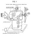
Figure 1 is a one-line diagram of a wind power generation system of Example 1. -
Figure 2 explains a pitch angle of a blade forming a wind turbine. -
Figure 3 shows a time chart of the wind power generation system of Example 1. -
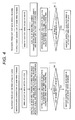
Figure 4 explains an operation flow of the wind power generation system of Example 1. -
Figure 5 shows a structure and one-line diagram of a wind power generation system of Example 2. -
Figure 6 shows a time chart of the wind power generation system of Example 2. -
Figure 7 explains an operation flow of the wind power generation system of Example 2. -
Figure 8 shows a structure and one-line diagram of a wind power generation system of Example 3. -
Figure 9 shows a time chart of the wind power generation system of Example 3. -
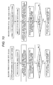
Figure 10 explains an operation flow of the wind power generation system of Example 3. -
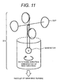
Figure 11 explains a vertical-axis type wind turbine. -
Figure 12 explains a vertical-axis type wind turbine. -
Figure 13 explains a wind turbine having a tail. - Hereafter, preferred examples to achieve the present invention are explained. The followings are just examples, and do not identify implementations.
- Example 1 is explained using
Figures 1 to 4 . As shown inFigure 1 , a wind power generation system of this example mainly includes amain wind turbine 1 to supply generated power to a load and a power grid and anauxiliary wind turbine 2 to supply power to after-mentioned auxiliary machines. - The
wind turbine 1 is built on a base, and includes acolumn 3 supporting theoverall wind turbine 1, anacelle 4 rotatably installed horizontally to thecolumn 3 at the upper part of thecolumn 3, and threeblades 5 that are placed at the head of thenacelle 4 and that rotate in response to the wind. Inside thenacelle 4, ashaft 6 and agenerator 7 that are connected to theblades 5 are placed. Theshaft 6 is connected to the rotation shaft of the rotor of thegenerator 7. As a result, as theblades 5 rotate, the rotor of thegenerator 7 rotates via theshaft 6, and thewind turbine 1 generates power. - The
wind turbine 1 in this example is a downwind type wind turbine that generates power while theblades 5 face downwind. - The
wind turbine 2 is a smaller wind turbine than thewind turbine 1 and installed on thenacelle 4 of thewind turbine 1. Thewind turbine 2 includes acolumn 8 that supports theoverall wind turbine 2 on thenacelle 4, anacelle 9 installed on the upper part of thiscolumn 8 horizontally to thecolumn 8, and threeblades 10 placed at the head of thenacelle 9 and rotating in response to the wind. Unlike thenacelle 4, thenacelle 9 is secured on the column and not rotatable horizontally. Inside thenacelle 9, ashaft 11 connected to theblades 10 and a permanentmagnet type generator 12 that may need no excitation current are placed. Theshaft 11 is connected to the rotation shaft of the rotor of thegenerator 12. As theblades 10 rotate, the rotor of thegenerator 12 rotates via theshaft 11, and thewind turbine 2 generates power. Theblades 10 face in the same direction as theblades 5. - The
blades 10 are secured to face in the same direction as theblades 5. Since power generation is performed while theblades 5 face downwind, thewind turbine 2 is also a downwind type wind turbine. - A
power conversion system 13 is connected to thegenerator 12, and converts a voltage of an irregular frequency in response to a time variation of the wind from thegenerator 12 to a rated frequency. A yaw (that means rotation in the horizontal plane perpendicular to the column 3)driving machine 14 and apitch driving machine 15 of thenacelle 4 are connected to the opposite end of thepower conversion system 13 to thegenerator 12. Theyaw driving machine 14 adjusts a rotational angle in the horizontal plane of thenacelle 4. In response to a wind direction obtained from an anemometer not shown, theblades 5 are adjusted to face downwind. The wind speed may be measured by the anemometer. The anemometer is able to be installed to or around the wind power generation system. As shown inFigure 2 , thepitch driving machine 15 changes a swept area of theblades 5 in the wind direction. A pitch angle of theblades 5 whose swept area is the largest and which faces perpendicularly to the wind direction is called a fine pitch angle. A pitch angle of theblades 5 whose swept area is the smallest is called a feather pitch angle. It is possible to angle theblades 5 intermediately of these extreme angles. In this example, theyaw driving machine 14 andpitch driving machine 15 are connected to thegenerator 12 via thepower conversion system 13. Theyaw driving machine 14,pitch driving machine 15, etc. that control the wind turbine are generally called auxiliary machines. - On the other hand, the
generator 7 of thewind turbine 1, which is the main wind turbine that supplies generated power to the load, is connected to aswitch 17 via apower converter 16 and to atransformer 18 via theswitch 17. After the transformer converts the generated power to a required voltage, the generated power is supplied to theload 19. In each example in this specification, the direct power supply to the load such as a micro grid or an offshore wind turbine is explained, in which the generated power is not supplied to the power grid. This is different from a method in which the power for auxiliary machines is provided from a conventional power grid and is temporarily provided from an uninterruptible power source in case of detachment of the auxiliary machines from the power grid. In each example, the power grid is not essential. It is possible to use the power generation system of each example in an independent power network. It is possible to place the power generation system in a region where a power network is not popular. Even when a power network is present, the power generation system is useful as an (additional) emergency power supply at the outage of a normal power supply (including an emergency power supply) due to a disaster etc. In a nuclear power plant etc. in which delay of cooling due to the outage of power supply may cause a serious accident, it is more effective that the power generation system of each example is connected to the nuclear power plant to supply power to the nuclear power plant as an emergency power generation system. In this power supply, cease of the power supply is able to be avoided by switching the power supply to the wind power generation system immediately when all the power supplies to the nuclear power plant stop. An outage of power supply can be determined, e.g., by installing a measurement device for voltage values and current values in the middle of a power supply circuit connected to other than a wind power generation system. A switch may be provided to switch the power supply circuit to the wind power generation system when a signal from the measurement device falls below a predetermined threshold or stops. Then, an instruction may be sent to the switch. - When the wind power generation system is combined with a nuclear power plant, it is assumed that it is difficult for the wind power generation system alone to provide the power, e.g., for cooling the nuclear power plant at a low wind speed. In such a case, a solar power generation system is effectively placed as an annex to complement the output from the wind power generation system. By use of complementary combination of the power generation system dependent on a wind speed and the power generation system dependent on solar radiation intensity, it becomes easier to avoid shortage of required power as compared to a case where the wind power generation system is used alone.
- More preferably, an auxiliary power supply battery is provided in the nuclear power plant, and the generated power from both of the power generation systems contributes to charging of the auxiliary power supply battery. Even when sufficient wind speed or sufficient solar radiation intensity is not obtained, power is able to be supplied to the nuclear power plant from the battery to more easily avoid shortage of the required power.
- As the operation method, the operation method of the wind power generation system exampled in each example is used. Within a wind speed range in which power generation is possible, the generated power from the wind power generation system may be supplied to the nuclear power plant and auxiliary power supply battery. Outside the wind speed range in which the power generation is possible, the generated power from the solar power generation system and/or the power from the auxiliary power supply battery may be supplied. As a result, the complementarity is improved therebetween.
- The above operation independent of the power grid is a major feature of the present invention shown in this specification. It is clear that power transmission to the power grid is also possible.
- The method for operating the wind power generation system constituted as mentioned above is explained using
Figure 3 andFigure 4 . The upper stage ofFigure 3 shows temporal variations of a wind speed measured by the anemometer. A cut-in wind speed shows a lowermost wind speed for the power generation by thewind turbine 1 or for the supply of generated power to the load by thewind turbine 1 without changing the pitch angle to a feather pitch angle. A cut-out wind speed shows an uppermost wind speed for the power generation by thewind turbine 1 or for the supply of the generated power to the load by thewind turbine 1 without changing the pitch angle to a feather pitch angle. That is, thewind turbine 1 generates power at or over the cut-in wind speed and at or under the cut-out wind speed. - In
Figure 3 , at first, the wind speed shows a uniform value in the wind speed range in which the power generation is possible, and is in the normal state. In this case, the pitch angle of theblades 5 is held around the intermediate angle between the fine pitch angle and feather pitch angle. Thegenerator 7 of the main wind turbine and thegenerator 12 of the auxiliary wind turbine generate power with holding generally constant rotational speeds. Theswitch 17 is closed (ON state) and the generated power from thegenerator 7 is supplied to theload 19. The generated power from thegenerator 12 is supplied also to the auxiliary machines. - Next, when the wind speed decreases suddenly to approach the cut-in wind speed, the pitch angle of the
blades 5 transitions to the fine pitch angle such that theblades 5 are exposed to as much wind as possible. However, as the wind itself weakens, the rotational speed of thegenerator 7 and the rotational speed of thegenerator 12 of the auxiliary wind turbine decrease. Also in this case, theswitch 17 is still in the closed state, and the generated power is supplied to the load. - When the wind speed decreases further and falls below the cut-in wind speed, the pitch angle of the
blades 5 is changed to the feather pitch angle in consideration of safety so that theblades 5 are not swept by the wind. Then, theblades 5 stop rotating, and thegenerator 7 that rotates with the rotation of theblades 5 and generates power stops generating power. As the power generation is stopped, theswitch 17 is opened (OFF state) to stop exchange between thegenerator 7 andload 19. The yaw is not controlled so that the yaw moves freely in response to the wind direction (free yaw). Since themain wind turbine 1 is the downwind type wind turbine, theblades 5 face downwind in case of free yaw like the so-called weathervane. On the other hand, the pitch angle is not controlled in the auxiliary wind turbine, theblades 10 rotate slowly, and thegenerator 12 continues power generation. Theauxiliary wind turbine 2 is not yawed, and is secured to thenacelle 4. The securednacelle 4 itself rotates in response to the wind direction. Since theblades 5 of thewind turbine 1, which is the downwind type wind turbine, and theblades 10 of theauxiliary wind turbine 2 face in the same direction, theblades 10 also face downwind. Thus, the power generation can be continued. The auxiliary machines only control the pitch angle and the yaw, and do not need large power. The power supply for the auxiliary machines can be provided by even low generated power. - When the wind speed decreases further in this condition and the wind stops substantially, it is also difficult for the auxiliary wind turbine to rotate. In this case, the auxiliary machine power is not supplied and the auxiliary machines are stopped safely.
- Then, when the wind speed increases again, the
blades 10 of the auxiliary wind turbine restart rotating, and the auxiliary machine power supply is provided by rotating thegenerator 12. The auxiliary machine power supply is provided to restart the auxiliary machines. Also in this state, theblades 5 of the main wind turbine are still in the feather pitch angle not to rotate. - When the wind speed increases further to exceed the cut-in wind speed again, the
pitch driving machine 15 changes the pitch angle from the feather pitch angle to fine pitch angle to rotate theblades 5. With the rotation of theblades 5, thegenerator 5 restarts power generation. Theyaw driving machine 14 performs the yaw control. At the same time, theswitch 17 is switched to the closed state to supply generated power to the load. After that, when the wind speed is between the cut-in wind speed and cut-out wind speed, thegenerator 7 maintains a certain rotation speed while adjusting the pitch angle. - When the wind speed becomes higher from this state, the pitch angle of the
blades 5 is made close to the feather pitch angle not to apply excess wind pressure to thewind turbine 1. At this time, the rotational speed of thegenerator 7 decreases suddenly. On the other hand, since the pitch-angle of theblades 10 of the auxiliary wind turbine is not controlled, its rotational speed continues to increase. - When the wind speed becomes stronger to exceed the cut-out wind speed, the pitch angle of the
blades 5 is switched to the feather pitch angle. Thereby, theblades 5 stop rotating, and thegenerator 7 also stops rotating. At the same time, theswitch 17 is opened (OFF state) not to exchange power between thegenerator 7 andload 19. A free yaw condition is set as in the case where the wind speed is below the cut-in wind speed. Since themain wind turbine 1 is the downwind type wind turbine, theblades 5 as well as the so-called weathervane face downwind in the free yaw condition. The auxiliary wind turbine is not yawed, and secured to thenacelle 4. Since theblades 10 face in the same direction as theblades 5 of the downwind type wind turbine, theblades 10 face downwind. Since the pitch angle of theblades 10 is not controlled, the power generation is performed in response to the wind. Accordingly, the power generation is able to be continued even when the wind speed is at the cut-out wind speed or more. Therefore, the driving power source for the auxiliary machines can be provided. - After that, when the wind speed is at the cut-out wind speed or less, the pitch angle of the
blades 5 shifts from the feather pitch angle to increase their swept area and to then rotate theblades 5. The yaw control is performed by theyaw driving machine 14. With the rotation of theblades 5, thegenerator 7 rotates to restart power generation. At the same time, theswitch 17 is switched to the closed state to provide generated power to the load. After that, when the wind speed is between the cut-in wind speed and cut-out wind speed, thegenerator 7 maintains a certain rotational speed while adjusting the pitch angle. - This flow is as shown in
Figure 4 . That is, when the wind speed is less than the cut-in wind speed, the pitch angle of the main wind turbine is changed to the feather pitch angle, and the free yaw condition is applied. As shown inFigure 4 , when the wind speed is less than the cut-in wind speed, the pitch angle is able to be in the fine pitch angle or in the intermediate angle between the feather pitch angle and fine pitch angle because it is difficult to consider that theblades 5 are swept by excess wind. Even when the wind speed is less than the cut-in wind speed, the auxiliary machine power supply is freely provided from the auxiliary wind turbine that faces downwind naturally to generate power without the yaw control. After that, when the wind speed is at the cut-in wind speed or more, the power generation can be restarted by performing the pitch-angle control and yaw control immediately. - When the wind speed exceeds the cut-out wind speed during the power generation by the main wind turbine, the pitch angle of the main wind turbine is changed to the feather pitch angle, and the yaw control enters the free yaw condition. Even when the wind speed exceeds the cut-out wind speed, the auxiliary machine power supply is freely provided from the auxiliary wind turbine that faces downwind naturally to generate power without the yaw control. After that, when the wind speed is at the cut-out wind speed or less, power generation is able to be restarted by performing the pitch-angle control and yaw control immediately.
- In this example, the auxiliary wind turbine is the downwind type wind turbine requiring no yaw control and uses the permanent magnet type generator requiring no excitation current. Therefore, the power generation is possible in response to the wind irrespective of the presence of and the state of the power grid. It is not important whether the generator of the main wind turbine is the permanent magnet type generator. The yaw control is considered to be performed by the yaw control power source from the auxiliary wind turbine itself during the power generation. To achieve a blackout start to generate power without an additional external power supply after the power supply stops completely, it is desirable to provide a mode in which power generation is started without the yaw control. It is not important whether the yaw control is performed after a start of power generation. The pitch-angle control of the auxiliary wind turbine is freely performed during the power generation. When the wind stops and the power generation is stopped, the auxiliary wind turbine may need to wait while the pitch angle is other than the feather pitch angle to restart in response to the wind. It is preferable to wait while the pitch angle is in or near the fine pitch angle.
- In this example, the auxiliary machine power supply is provided from only the auxiliary wind turbine. The supply from the
generator 7 of the main wind turbine to the auxiliary machines is not excluded. When the main wind turbine is normal and a certain fault occurs in the auxiliary wind turbine, power is to be supplied to the load. When the auxiliary machine power supply is provided from only the auxiliary wind turbine, it is difficult to supply generated power to the load. Therefore, it is desirable that the auxiliary machine power supply is able to be supplied from both the auxiliary wind turbine and the main wind turbine. - In this example, the auxiliary wind turbine is smaller than the main wind turbine. Accordingly, the
blades 10 become lighter than theblades 5 to rotate even by weak wind. That is, even the wind of less than the cut-in wind speed is able to rotate theblades 10 of the auxiliary wind turbine to provide the auxiliary machine power supply. The stress applied to the wind turbine may be contributed by the n-th power of the rotor diameter of the blades when the strong wind blows. As a result, the stress applied to the wind turbine becomes large as the blades are enlarged. Therefore, the auxiliary machine power supply can be provided by using the small wind turbine even in case of a storm exceeding the cut-out wind speed. Therefore, when the main wind turbine rotates in response to the wind equal to or over the cut-in wind speed and equal to or under the cut-out wind speed, the small wind turbine rotates. As a result, the auxiliary machine power supply is provided constantly. That is, irrespective of the state of the power grid, when the main wind turbine is able to generate power, the power generation is possible, and the operation time in which the wind turbine contributes to the power generation is made the maximum. - In this example, the auxiliary wind turbine is secured to cause the
blades 10 to face downwind in the same direction as theblades 5 with securing the yaw drive. In light of the fact that the main wind turbine is the downwind type wind turbine and faces downwind constantly, the auxiliary wind turbine is able to be used as an upwind type wind turbine facing in the opposite direction to theblades 5 when the yaw drive is secured. - When the auxiliary wind turbine is used as the downwind type wind turbine, the yaw drive is in the free yaw condition and is not secured. When the auxiliary wind turbine is used as the downwind type wind turbine and the yaw drive is in the free yaw condition, the auxiliary wind turbine does not need to be placed on the
nacelle 4 of the main wind turbine, and can be installed on a different place. - Example 2 is explained using
Figures 5 to 7 . This example is the most different from Example 1 in that amain wind turbine 20 is an upwind type wind turbine operating with facing upwind. In this example, the yaw drive of a nacelle of anauxiliary wind turbine 21 is in the free yaw condition. - In the following, only the difference between this example and Example 1 is explained, and the similar explanation to that of Example 1 is abbreviated.
- As shown in
Figure 5 , when the structure of the wind power generation system itself is the same as Example 1 except that this example uses the upwind type wind turbine and Example 1 uses the downwind type wind turbine. -
Figure 6 shows a time chart. The same operation as Example 1 is possible roughly over an approximate elapse of time. -
Figure 7 shows an operation procedure as a flowchart. When the upwind type wind turbine is used, when the wind is under the cut-in wind speed, and when the wind is over the cut-out wind speed, the yaw is secured not to rotate naturally, and stopped. In the case where the wind is once under the cut-in wind speed or where the wind is over the cut-out wind speed, when the wind speed returns to the cut-in wind speed or more and to the cut-out wind speed or less, the yaw may need to be controlled to make theblades 5 of themain wind turbine 20 face upwind at first. The auxiliary machine power supply in this case is provided from the generated power of the auxiliary wind turbine. The yaw drive of theauxiliary wind turbine 21 in this example is in the free yaw condition. As in a weathervane, theblades 10 of theauxiliary wind turbine 21 rotate to face downwind although thenacelle 4 of themain wind turbine 20 is secured. - As in this example, even when the main wind turbine is the upwind type wind turbine, power generation is possible in response to the wind irrespective of the presence of and the state of the power grid.
- Example 3 is explained using
Figures 8 to 10 . The similar explanation to those of the above examples is abbreviated. As shown inFigure 8 , in the wind power generation system of this example, unlike each of the above examples, only amain wind turbine 23, which is the downwind type wind turbine, is used and no auxiliary wind turbine is provided. Agenerator 24 in this example uses the permanent magnet type generator. Thegenerator 24 is connected topower conversion systems power conversion system 25 corresponds to thepower conversion system 13 of each of the above examples. Theyaw driving machine 14 and thepitch driving machine 15 are connected ahead of thepower conversion system 25. Thepower conversion system 26 corresponds to thepower conversion system 16 of each above-mentioned example. Aswitch 28 is connected ahead of thepower conversion system 26. Aload 30 is connected ahead of theswitch 28 via atransformer 29. Themain wind turbine 23 in this example is the main wind turbine, and also functions as the auxiliary wind turbine in each of the above examples. -
Figure 9 shows a time chart. The cut-in wind speed in this example expresses the lowermost wind speed when thewind turbine 23 supplies the generated power to the load, and the cut-out wind speed expresses the uppermost wind speed in this example when thewind turbine 23 supplies the generated power to the load. InFigure 9 , at first, the wind speed shows a constant value in the wind speed range in which the power generation is possible and is in the normal state. In this case, the pitch angle of theblades 5 is maintained at or near an intermediate angle between the fine pitch angle and feather pitch angle. Thegenerator 7 of the main wind turbine generates power while maintaining a generally uniform rotational speed. Theswitch 17 is closed (ON state) and the generated power from thegenerator 7 is supplied to theload 19. - Next, when the wind speed decreases suddenly to approach the cut-in wind speed, the pitch angle of the
blades 5 transitions to the fine pitch angle such that theblades 5 are exposed to as much wind as possible. However, as the wind itself weakens, the rotational speeds of thegenerator 7 and thegenerator 12 of the auxiliary wind turbine decreases. Also in this case, theswitch 17 is still in the closed state, and the generated power is supplied to the load. - In each of the above examples, when the wind speed decreases to be below the cut-in wind speed, the pitch angle of the
blades 5 transitions to the feather pitch angle so that theblades 5 are not exposed to the wind. In this example, theblades 5 are left in the fine pitch angle. When the wind speed is below the cut-in wind speed, theswitch 28 is opened (OFF state) not to exchange power between thegenerator 24 andload 30. The yaw is made free in response to the wind direction (free yaw) without the yaw control. Themain wind turbine 23 is the downwind type wind turbine. Accordingly, in the free yaw condition, theblades 5 always face downwind to continue rotating and thegenerator 24 continues generating power. Since the auxiliary machines only control the pitch angle, the yaw, etc. and do not require great power, the auxiliary machine power supply can be provided even by low generated power. - When the wind speed decreases further in this state and the wind stops substantially, it is difficult to rotate the main wind turbine of this example. In this case, the auxiliary machine power supply is not provided, and the auxiliary machines are stopped safely.
- After that, when the wind speed increases again, the
blades 5 of themain wind turbine 23 restart rotating, and the auxiliary machine power supply is provided by rotation of thegenerator 24. As a result, the auxiliary machine power supply is provided, and the auxiliary machines restart. - When the wind speed increases further to be over the cut-in wind speed again, the
switch 28 transitions to the closed state. Accordingly, the generated power is supplied to the load. After that, when the wind speed is between the cut-in wind speed and cut-out wind speed, the rotational speed of thegenerator 7 is maintained at a constant rotational speed while adjusting the pitch angle. - When the wind speed becomes higher from this condition, the pitch angle of the
blades 5 is made close to the feather pitch angle to apply no excess wind pressure to thewind turbine 1. At this time, the rotational speed of thegenerator 24 decreases suddenly. Also in this case, since the auxiliary machines may not require high power, the auxiliary machine power supply can be provided by low generated power. - When the wind speed becomes higher to exceed the cut-out wind speed, the pitch angle of the
blades 5 is switched to near the feather pitch angle. This is because, when the pitch angle is completely in the feather pitch angle, the rotation of theblades 5 stops, and it is difficult to restart the rotation. In consideration of safety of the wind turbine, it is necessary that theblades 5 are rotatable. The pitch angle may be positioned such that the rotational speed of theblades 5 is maintained to provide the auxiliary machine power supply by the generated power of thegenerator 24 at the cut-out wind speed. In this case, the yaw control of themain wind turbine 23 is released to be in the free yaw condition. Since themain wind turbine 23 is the downwind type wind turbine, theblades 5 face downwind in the free yaw condition. At more than the cut-out wind speed, the pitch angle of theblades 5 is not completely in the feather pitch angle, but is near the feather pitch angle. Therefore, even over the cut-out wind speed, the power generation can be continued. Therefore, the driving power source of the auxiliary machines can be provided. - After that, when the wind speed is at the cut-out wind speed or below, the pitch angle of the
blades 5 is changed from the feather pitch angle to enlarge the swept area to rotate theblades 5. Theyaw driving machine 14 performs yaw control. When the wind speed is at the cut-out wind speed or below, theswitch 28 is switched to the closed state to supply the generated power to the load. After that, when the wind speed is between the cut-in wind speed and the cut-out wind speed, thegenerator 24 maintains a certain rotational speed while adjusting the pitch angle. - This flow is organized as shown in
Figure 10 . That is, as the wind speed approaches the cut-in wind speed during the power generation of the main wind turbine, the pitch angle of the main wind turbine is changed to the fine pitch angle, and when the wind speed is below the cut-in wind speed, the yaw control transitions to the free yaw condition. Even when the wind speed is below the cut-in wind speed, the auxiliary machine power supply is freely provided from the auxiliary wind turbine because the main wind turbine is the downwind type wind turbine and the auxiliary wind turbine faces downwind naturally without the yaw control. After that, when the wind speed is over the cut-in wind speed, the pitch-angle control and yaw control are performed immediately, theswitch 28 is made to enter the closed state, and thus the supply of the generated power to the load can be restarted. - When the wind speed exceeds the cut-out wind speed during the power generation of the main wind turbine, the pitch angle of the main wind turbine is changed to near the feather pitch angle, and the yaw control transitions to the free yaw condition. Even when the wind speed exceeds the cut-out wind speed, the auxiliary machine power supply is freely provided from the
main wind turbine 23 because themain wind turbine 23 is the downwind type wind turbine to face downwind naturally without the yaw control. After that, when the wind speed is at the cut-out wind speed or below, the pitch-angle control and yaw control are performed immediately, and the power generation can be restarted by closing theswitch 28. - According to this example, as described in each of the above examples, when the wind blows, the power generation can be performed without the auxiliary wind turbine irrespective of the presence of and the state of the power grid.
- In the above examples, the use of the downwind type wind turbine as the auxiliary wind turbine is explained. Instead of the downwind type wind turbine, any wind turbine that is able to generate power and to control a yaw without an auxiliary machine, such as vertical-axis
type wind turbines Figure 11 andFigure 12 that generate power irrespective of a wind direction and a wind turbine with a tail shown inFigure 13 , can be used. - In each of the above examples, the permanent magnet type generator is mounted to at least one of the auxiliary wind turbine and the main wind turbine (in Example 3, only to the main wind turbine). Instead of this permanent magnet type generator, an excitation type generator and a battery that provides an initial excitation power for excitation type generator can be provided.
- In this case, the excitation type generator during power generation may need to provide its own excitation power by itself, and to charge the battery by its own generated power to be ready for the subsequent restarts.
-
- 1, 2, 20, 21, 23
- wind turbines
- 3, 8
- column
- 4, 9, 22
- nacelle
- 5, 10
- blade
- 6, 11
- shaft
- 7, 12, 24
- generator
- 13, 16, 25, 26
- power conversion system
- 14, 27
- yaw driving machine
- 15
- pitch driving machine
- 17, 28
- switch
- 18, 29
- transformer
- 19, 30
- load
Claims (23)
- A wind power generation system comprising a wind turbine,
the wind turbine including:a blade that rotates in response to wind;a generator that rotates with rotation of the blade to generate power; andan auxiliary machine that controls a pitch angle of the blade,wherein the auxiliary machine is driven by generated power of a downwind type wind turbine to which a permanent magnet type generator is mounted and which generates power in a state in which a blade of the downwind type wind turbine rotating in response to wind faces downwind. - A wind power generation system comprising a wind turbine,
the wind turbine including:a blade that rotates in response to wind;a generator that rotates with rotation of the blade to generate power; andan auxiliary machine that controls a pitch angle of the blade,wherein an excitation type generator and a battery that provides an initial excitation power for the excitation type generator are mounted,wherein excitation power of the excitation type generator during power generation is provided by generated power of the excitation type generator, the battery is charged by the generated power of the excitation type generator, andthe auxiliary machine is driven by generated power of a downwind type wind turbine that generates power in a state in which a blade of the downwind type wind turbine rotating in response to wind faces downwind. - The wind power generation system according to claim 1 or 2, wherein the wind power generation system is connected to a load without a power grid.
- The wind power generation system according to any one of claims 1 to 3,
wherein the first mentioned wind turbine and the downwind type wind turbine are different from one another, and the downwind type wind turbine is smaller than the first mentioned wind turbine. - The wind power generation system according to claim 4,
wherein the first mentioned wind turbine has a column, the blade, and a nacelle to which the blade are attached and which is rotatably supported by the column in a horizontal plane, and
the downwind type wind turbine is mounted to the nacelle. - The wind power generation system according to claim 5,
wherein the first mentioned wind turbine is a second downwind type wind turbine that generates power in a state in which the blade of the first mentioned wind turbine faces downwind. - The wind power generation system according to claim 6,
wherein the downwind type wind turbine is mounted to the nacelle such that the blade of the downwind type wind turbine faces in a same direction as the blade of the second downwind type wind turbine. - The wind power generation system according to claim 4,
wherein the first mentioned wind turbine is an upwind type wind turbine that generates power in a state in which the blade of the first mentioned wind turbine faces upwind. - The wind power generation system according to claim 8,
wherein the blade of the downwind type wind turbine are placed rotatably in a horizontal plane without yaw control. - The wind power generation system according to any one of claims 1 to 3,
wherein the first mentioned wind turbine and the downwind type wind turbine are a same wind turbine. - The wind power generation system according to any one of claims 1 to 10,
wherein the wind power generation system is connected to a nuclear power plant and is able to supply power to the nuclear power plant. - An emergency power supply system comprising:the wind power generation system according to claim 11;a switch to switch a power supply circuit from the wind power generation system for the nuclear power plant and another power supply circuit for the nuclear power plant;a measurement device provided in the another power supply circuit to measure a voltage value or a current value in the circuit; anda means to output a signal of switching the switch when a measurement value from the measurement device is below a predetermined threshold or when a signal from the measurement device stops.
- An emergency power supply system, comprising:the wind power generation system according to claim 11;a solar power generation system that is connected to the nuclear power plant and is able to supply power to the nuclear power plant; anda battery that is connected to the nuclear power plant and is able to supply power to the nuclear power plant,wherein the battery is chargeable by generated power of the wind power generation system or of the solar power generation system.
- A method for operating a wind power generation system, the system comprising:a main wind turbine that generates mainly power supplied to a load and/or a power grid;an auxiliary wind turbine that supplies generated power to an auxiliary machine that controls a pitch angle of the main wind turbine and an auxiliary machine that controls a yaw of the main wind turbine, that is a downwind type wind turbine that generates power in a state in which a blade of the auxiliary wind turbine faces downwind, and to which a permanent magnet type generator is mounted; andan anemometer that measures a wind speed,wherein the downwind type wind turbine is able to generate power in a wider wind speed range than a wind speed range in which power generation by the main wind turbine is possible,the auxiliary wind turbine rotates in a free yaw condition until the wind speed returns to within the wind speed range in which the power generation by the main wind turbine is possible after the wind speed is out of the wind speed range in which the power generation by the main wind turbine is possible, generated power of the auxiliary wind turbine drives the auxiliary machines to control the pitch angle and yaw of the main wind turbine when the wind speed returns to within the wind speed range in which the power generation by the main wind turbine is possible, and the power generation of the main wind turbine is restarted.
- The method for operating a wind power generation system according to claim 14,
wherein the downwind type wind turbine is able to generate power at a lower wind speed than a cut-in wind speed of the wind speed range in which the power generation by the main wind turbine is possible,
the auxiliary wind turbine is able to rotate in the free yaw condition until the wind speed returns to the cut-in wind speed of the main wind turbine or more after the wind speed is below the cut-in wind speed, generated power of the auxiliary wind turbine drives the auxiliary machines to control the pitch angle and yaw of the main wind turbine when the wind speed returns to the cut-in wind speed or more, and power generation of the main wind turbine is restarted. - The method for operating a wind power generation system according to claim 14 or 15,
wherein the downwind type wind turbine is able to generate power at a higher wind speed than a cut-out wind speed of the wind speed range in which the power generation by the main wind turbine is possible,
the auxiliary wind turbine is able to rotate in the free yaw condition until the wind speed returns to the cut-out wind speed of the main wind turbine or less after the wind speed is over the cut-out wind speed, generated power of the auxiliary wind turbine drives the auxiliary machines to control the pitch angle and yaw of the main wind turbine when the wind speed returns to the cut-out wind speed or less, and power generation of the main wind turbine is restarted. - The method for operating a wind power generation system according to claim 16,
wherein the pitch angle of the main wind turbine is in a feather pitch angle until the wind speed is returned to the cut-out wind speed of the main wind turbine or less after the wind speed is over the cut-out wind speed. - The method for operating a wind power generation system according to any one of claims 14 to 17,
wherein the main wind turbine is the downwind type wind turbine that generates power in a state in which a blade of the main wind turbine faces downwind. - The method for operating a wind power generation system according to any one of claims 14 to 17,
wherein the main wind turbine is an upwind type wind turbine that generates power in a state in which a blade of the main wind turbine faces upwind, and
the blade of the main wind turbine is controlled to face upwind before a restart of the power generation of the main wind turbine. - A method for operating a wind power generation system, the system comprising:a main wind turbine that generates mainly power supplied to a load and/or a power grid;an auxiliary wind turbine that supplies generated power to an auxiliary machine that controls a pitch angle of the main wind turbine and an auxiliary machine that controls a yaw of the main wind turbine, that is a downwind type wind turbine that generates power in a state in which a blade of the auxiliary wind turbine faces downwind, and to which a permanent magnet type generator is mounted; andan anemometer that measures a wind speed,wherein the main wind turbine is able to rotate in a free yaw condition until a wind speed returns to within a wind speed range in which power generation by the main wind turbine is possible after the wind speed is out of the wind speed range in which the power generation by the main wind turbine is possible, generated power of the main wind turbine drives the auxiliary machine to control the pitch angle and yaw of the main wind turbine when the wind speed returns to within the wind speed range in which the power generation by the main wind turbine is possible, and the power generation of the main wind turbine is restarted.
- The method for operating a wind power generation system according to claim 18,
wherein a pitch angle of the blade of the main wind turbine is in a fine pitch angle until the wind speed returns to the cut-in wind speed of the main wind turbine or more after the wind speed of the main wind turbine is below the cut-in wind speed. - The method for operating a wind power generation system according to claim 20 or 21,
wherein the pitch angle of the blades is near a feather pitch angle until the wind speed returns to a cut-out wind speed of the main wind turbine or below after the wind speed is over the cut-out wind speed. - A method for operating a nuclear power plant using the method according to any one of claims 14 to 22,
wherein the wind power generation system is connected to a nuclear power plant and able to supply power to the nuclear power plant,
the nuclear power plant is connected also to a solar power generation system and able to receive power from the solar power generation system,
the wind power generation system and the solar power generation system are connected to an auxiliary power supply battery of the nuclear power plant,
the wind power generation system supplies generated power to the nuclear power plant and/or the auxiliary power supply battery within the wind speed range in which the power generation is possible, and
generated power from the solar power generation system or power from the auxiliary power supply battery is supplied to the nuclear power plant outside the wind speed range in which the power generation is possible.
Applications Claiming Priority (1)
| Application Number | Priority Date | Filing Date | Title |
|---|---|---|---|
| PCT/JP2011/002399 WO2012147118A1 (en) | 2011-04-25 | 2011-04-25 | Wind power generation system, device using wind power generation system, and method for operating same |
Publications (3)
| Publication Number | Publication Date |
|---|---|
| EP2703643A1 true EP2703643A1 (en) | 2014-03-05 |
| EP2703643A4 EP2703643A4 (en) | 2014-10-08 |
| EP2703643B1 EP2703643B1 (en) | 2018-06-13 |
Family
ID=47071672
Family Applications (1)
| Application Number | Title | Priority Date | Filing Date |
|---|---|---|---|
| EP11864572.0A Active EP2703643B1 (en) | 2011-04-25 | 2011-04-25 | Wind power generation system, device using wind power generation system, and method for operating same |
Country Status (8)
| Country | Link |
|---|---|
| US (1) | US9231441B2 (en) |
| EP (1) | EP2703643B1 (en) |
| JP (1) | JP5619278B2 (en) |
| KR (1) | KR20140003608A (en) |
| CN (1) | CN103518060A (en) |
| AU (1) | AU2011366415A1 (en) |
| CA (1) | CA2834361A1 (en) |
| WO (1) | WO2012147118A1 (en) |
Cited By (4)
| Publication number | Priority date | Publication date | Assignee | Title |
|---|---|---|---|---|
| EP2963288A1 (en) * | 2014-07-03 | 2016-01-06 | Hitachi Ltd. | Downwind type windturbine and method of stopping such windturbine |
| WO2020127206A1 (en) * | 2018-12-21 | 2020-06-25 | Cotes A/S | Windturbine dehumidifier system comprising secondary wind power source |
| NL2035205A (en) * | 2023-02-16 | 2023-08-11 | Huaneng Renewables Corporation Ltd Hebei Branch | A wind power generation system based on a wind turbine |
| US12410770B2 (en) | 2020-03-10 | 2025-09-09 | Vestas Wind Systems A/S | Method for controlling a multirotor wind turbine |
Families Citing this family (16)
| Publication number | Priority date | Publication date | Assignee | Title |
|---|---|---|---|---|
| ITRM20110516A1 (en) * | 2011-09-30 | 2013-03-31 | Enel Green Power Spa | HORIZONTAL AXIS WIND GENERATOR WITH SECONDARY WIND ROTOR |
| WO2013060013A1 (en) * | 2011-10-28 | 2013-05-02 | General Electric Company | Blade pitch system for a wind turbine generator and method of operating the same |
| EP2645530B1 (en) * | 2012-03-27 | 2018-08-15 | Siemens Aktiengesellschaft | Method for controlling a wind farm, wind farm controller, wind farm, computer-readable medium and program element |
| US9388792B2 (en) * | 2013-03-15 | 2016-07-12 | Frontier Wind, Llc | Distributed control system |
| US20140312620A1 (en) * | 2013-04-17 | 2014-10-23 | General Electric Company | Method and apparatus for improving grid stability in a wind farm |
| JP6142992B2 (en) * | 2013-04-22 | 2017-06-07 | 株式会社Ihi | Ocean current power generator |
| CN103795184B (en) * | 2014-02-21 | 2016-06-08 | 北京交通大学 | A kind of hybrid excitation generator cooperation electromotor coaxial with influence generator |
| JP6464043B2 (en) * | 2015-06-24 | 2019-02-06 | 株式会社日立製作所 | Wind power generator, wind farm, and wind farm control method |
| JP6509661B2 (en) * | 2015-07-15 | 2019-05-08 | 誠太 一色 | Wind power generator |
| DE102016103254A1 (en) * | 2016-02-24 | 2017-08-24 | Wobben Properties Gmbh | Method for determining an equivalent wind speed |
| JP2020002781A (en) * | 2018-06-25 | 2020-01-09 | 株式会社日立製作所 | Control method of wind power generator |
| EP3712427A1 (en) * | 2019-03-22 | 2020-09-23 | Siemens Gamesa Renewable Energy A/S | Wind turbine |
| EP3872335A1 (en) * | 2020-02-25 | 2021-09-01 | Siemens Gamesa Renewable Energy A/S | Wind turbine operable in a reverse mode of operation and corresponding method of operating a wind turbine |
| CN111306001B (en) * | 2020-03-02 | 2023-09-08 | 西安交通大学 | A wind and solar reactor system and its working method |
| CN114233564A (en) * | 2021-11-16 | 2022-03-25 | 上海致远绿色能源股份有限公司 | Variable-pitch power supply device of megawatt fan by using small fan |
| CN116722782B (en) * | 2023-08-10 | 2024-12-17 | 中山大洋电机股份有限公司 | Method for controlling galloping start of permanent magnet synchronous motor by using vector without position sensor |
Family Cites Families (35)
| Publication number | Priority date | Publication date | Assignee | Title |
|---|---|---|---|---|
| DE2742559C2 (en) * | 1977-09-22 | 1979-06-13 | Voith Getriebe Kg, 7920 Heidenheim | Wind energy converter |
| JPS61167482U (en) | 1985-04-09 | 1986-10-17 | ||
| JPH06289189A (en) | 1993-04-06 | 1994-10-18 | Toshiba Corp | Dc power source equipment for nuclear power plant |
| KR960007401B1 (en) * | 1994-06-27 | 1996-05-31 | 신찬 | Multi-unit rotor blade system integrated wind turbine |
| JP3227355B2 (en) | 1995-08-22 | 2001-11-12 | 松尾橋梁株式会社 | Wind power generation equipment |
| JPH1194988A (en) | 1997-09-19 | 1999-04-09 | Toshiba Eng Co Ltd | Emergency power supply equipment for nuclear power plants |
| DE10009472C2 (en) * | 2000-02-28 | 2002-06-13 | Norbert Hennchen | Device for adjusting the angle of attack of the rotor blades of a wind turbine which are rotatably arranged on a hub of a rotor shaft |
| DE20020232U1 (en) | 2000-11-29 | 2002-01-17 | Siemens AG, 80333 München | Wind turbine with auxiliary energy device for adjusting rotor blades in the event of a fault |
| DE10136974A1 (en) * | 2001-04-24 | 2002-11-21 | Aloys Wobben | Method for operating a wind turbine |
| CN1284928C (en) * | 2001-12-28 | 2006-11-15 | 三菱重工业株式会社 | Upwind wind turbine and method of operation thereof |
| JP2004108163A (en) * | 2002-09-13 | 2004-04-08 | Mitsubishi Heavy Ind Ltd | Windmill provided with wing passage area regulating device, and method for operating the same |
| US7071578B1 (en) | 2002-01-10 | 2006-07-04 | Mitsubishi Heavy Industries, Ltd. | Wind turbine provided with a controller for adjusting active annular plane area and the operating method thereof |
| JP2004044508A (en) * | 2002-07-12 | 2004-02-12 | Toshiba Corp | Wind power plant |
| US8072584B2 (en) * | 2002-08-02 | 2011-12-06 | Ophir Corporation | Optical air data systems and methods |
| US20040096327A1 (en) * | 2002-11-14 | 2004-05-20 | Kari Appa | Method of increasing wind farm energy production |
| US6921985B2 (en) | 2003-01-24 | 2005-07-26 | General Electric Company | Low voltage ride through for wind turbine generators |
| JP4416444B2 (en) | 2003-07-14 | 2010-02-17 | 富士重工業株式会社 | Wind generator protection system |
| JP4451729B2 (en) | 2004-06-21 | 2010-04-14 | 富士重工業株式会社 | Horizontal axis windmill |
| JP4690829B2 (en) * | 2005-08-30 | 2011-06-01 | 富士重工業株式会社 | Horizontal axis windmill |
| WO2006129509A1 (en) * | 2005-05-31 | 2006-12-07 | Fuji Jukogyo Kabushiki Kaisha | Horizontal axis windmill |
| ES2265771B1 (en) * | 2005-07-22 | 2008-01-16 | GAMESA INNOVATION & TECHNOLOGY, S.L. | METHOD FOR MAINTAINING THE COMPONENTS OF A WIND TURBINE AND A WIND TURBINE WITH COMPONENTS THAT ALLOW OPERATING MAINTENANCE. |
| JP4773850B2 (en) * | 2006-03-08 | 2011-09-14 | 三菱重工業株式会社 | Wind power generation system and emergency power supply method for wind power generation system |
| JP4872393B2 (en) * | 2006-03-14 | 2012-02-08 | 株式会社日立製作所 | Wind power generation hydrogen production system |
| NZ556760A (en) * | 2007-07-26 | 2008-12-24 | Auckland Uniservices Ltd | An electric generator |
| EP2166225B1 (en) * | 2008-09-19 | 2016-08-10 | Vestas Wind Systems A/S | A wind park having an auxiliary power supply |
| AU2009301600B2 (en) | 2008-10-09 | 2015-04-09 | Biro Air Energy Inc. | Wind powered apparatus having counter rotating blades |
| US20100090463A1 (en) * | 2008-10-10 | 2010-04-15 | Jacob Johannes Nies | Combined environmental monitoring and power supply device |
| US20110082598A1 (en) * | 2009-10-02 | 2011-04-07 | Tod Boretto | Electrical Power Time Shifting |
| US8866334B2 (en) * | 2010-03-02 | 2014-10-21 | Icr Turbine Engine Corporation | Dispatchable power from a renewable energy facility |
| US8378516B2 (en) * | 2010-04-07 | 2013-02-19 | Tai Koan Lee | Continuous wind power system with auxiliary blades |
| US9203334B2 (en) * | 2010-06-30 | 2015-12-01 | Hitachi, Ltd. | Wind power generator system, and control method for the same |
| WO2012103894A2 (en) * | 2011-02-04 | 2012-08-09 | Vestas Wind Systems A/S | A wind turbine arrangement with a main wind turbine and at least one secondary wind turbine |
| US9404479B2 (en) * | 2011-03-22 | 2016-08-02 | Tufts University | Systems, devices and methods for improving efficiency of wind power generation systems |
| ITRM20110516A1 (en) * | 2011-09-30 | 2013-03-31 | Enel Green Power Spa | HORIZONTAL AXIS WIND GENERATOR WITH SECONDARY WIND ROTOR |
| US20130270823A1 (en) * | 2012-04-17 | 2013-10-17 | Clipper Windpower, Llc | Method for Enhancing Low Voltage Ride Through Capability on a Wind Turbine |
-
2011
- 2011-04-25 US US14/113,770 patent/US9231441B2/en not_active Expired - Fee Related
- 2011-04-25 JP JP2013511792A patent/JP5619278B2/en active Active
- 2011-04-25 KR KR1020137027932A patent/KR20140003608A/en not_active Ceased
- 2011-04-25 EP EP11864572.0A patent/EP2703643B1/en active Active
- 2011-04-25 CA CA2834361A patent/CA2834361A1/en not_active Abandoned
- 2011-04-25 WO PCT/JP2011/002399 patent/WO2012147118A1/en not_active Ceased
- 2011-04-25 CN CN201180070410.8A patent/CN103518060A/en active Pending
- 2011-04-25 AU AU2011366415A patent/AU2011366415A1/en not_active Abandoned
Cited By (4)
| Publication number | Priority date | Publication date | Assignee | Title |
|---|---|---|---|---|
| EP2963288A1 (en) * | 2014-07-03 | 2016-01-06 | Hitachi Ltd. | Downwind type windturbine and method of stopping such windturbine |
| WO2020127206A1 (en) * | 2018-12-21 | 2020-06-25 | Cotes A/S | Windturbine dehumidifier system comprising secondary wind power source |
| US12410770B2 (en) | 2020-03-10 | 2025-09-09 | Vestas Wind Systems A/S | Method for controlling a multirotor wind turbine |
| NL2035205A (en) * | 2023-02-16 | 2023-08-11 | Huaneng Renewables Corporation Ltd Hebei Branch | A wind power generation system based on a wind turbine |
Also Published As
| Publication number | Publication date |
|---|---|
| US20140103656A1 (en) | 2014-04-17 |
| WO2012147118A1 (en) | 2012-11-01 |
| KR20140003608A (en) | 2014-01-09 |
| JPWO2012147118A1 (en) | 2014-07-28 |
| EP2703643A4 (en) | 2014-10-08 |
| JP5619278B2 (en) | 2014-11-05 |
| EP2703643B1 (en) | 2018-06-13 |
| CN103518060A (en) | 2014-01-15 |
| CA2834361A1 (en) | 2012-11-01 |
| AU2011366415A1 (en) | 2013-11-14 |
| US9231441B2 (en) | 2016-01-05 |
Similar Documents
| Publication | Publication Date | Title |
|---|---|---|
| US9231441B2 (en) | Wind power generation system, device using wind power generation system, and method for operating same | |
| JP4299334B2 (en) | Wind park operation method | |
| JP6491756B2 (en) | Method for operating a wind farm | |
| DK1865198T3 (en) | Emergency power supply device for pitch drive for a wind turbine | |
| US11434871B2 (en) | Black start restoration | |
| EP2101392B1 (en) | Wind turbine energy storage and frequency control | |
| EP2451073B1 (en) | Variable-speed power generation device and control method therefor | |
| CA2748460C (en) | Wind turbine with lvrt capabilities | |
| ES2663707T3 (en) | Wind turbine that provides network support | |
| CN103527407A (en) | Method and arrangement for responding to a grid event, such as fast frequency drop, by combining demand response, inertial response and spinning reserve | |
| KR20190039295A (en) | Method for controlling a wind turbine | |
| CN114729624A (en) | Auxiliary power system control for hybrid power plant | |
| CA2728788A1 (en) | Control system of wind power generator, wind farm, and method for controlling wind power generator | |
| CA2905643A1 (en) | Wind park and method for controlling a wind park | |
| CN107407257A (en) | Method for running wind turbine | |
| KR20120094238A (en) | Decreasing the standby power for wind turbine generator system | |
| CN108667366A (en) | A self-enclosed electromagnetic coupling speed-adjustable wind turbine control method using active power priority mode | |
| TW201341655A (en) | Wind power generating system | |
| JP2020002859A (en) | Wind power generator and control method for wind power generator |
Legal Events
| Date | Code | Title | Description |
|---|---|---|---|
| PUAI | Public reference made under article 153(3) epc to a published international application that has entered the european phase |
Free format text: ORIGINAL CODE: 0009012 |
|
| 17P | Request for examination filed |
Effective date: 20131125 |
|
| AK | Designated contracting states |
Kind code of ref document: A1 Designated state(s): AL AT BE BG CH CY CZ DE DK EE ES FI FR GB GR HR HU IE IS IT LI LT LU LV MC MK MT NL NO PL PT RO RS SE SI SK SM TR |
|
| DAX | Request for extension of the european patent (deleted) | ||
| A4 | Supplementary search report drawn up and despatched |
Effective date: 20140904 |
|
| RIC1 | Information provided on ipc code assigned before grant |
Ipc: F03D 1/02 20060101ALI20140829BHEP Ipc: F03D 9/00 20060101AFI20140829BHEP Ipc: F03D 7/02 20060101ALI20140829BHEP |
|
| STAA | Information on the status of an ep patent application or granted ep patent |
Free format text: STATUS: EXAMINATION IS IN PROGRESS |
|
| 17Q | First examination report despatched |
Effective date: 20161215 |
|
| REG | Reference to a national code |
Ref country code: DE Ref legal event code: R079 Ref document number: 602011049330 Country of ref document: DE Free format text: PREVIOUS MAIN CLASS: F03D0009000000 Ipc: F03D0009250000 |
|
| GRAP | Despatch of communication of intention to grant a patent |
Free format text: ORIGINAL CODE: EPIDOSNIGR1 |
|
| STAA | Information on the status of an ep patent application or granted ep patent |
Free format text: STATUS: GRANT OF PATENT IS INTENDED |
|
| RIC1 | Information provided on ipc code assigned before grant |
Ipc: F03D 7/02 20060101ALI20171121BHEP Ipc: F03D 9/25 20160101AFI20171121BHEP Ipc: F03D 1/02 20060101ALI20171121BHEP |
|
| INTG | Intention to grant announced |
Effective date: 20171205 |
|
| GRAS | Grant fee paid |
Free format text: ORIGINAL CODE: EPIDOSNIGR3 |
|
| GRAA | (expected) grant |
Free format text: ORIGINAL CODE: 0009210 |
|
| STAA | Information on the status of an ep patent application or granted ep patent |
Free format text: STATUS: THE PATENT HAS BEEN GRANTED |
|
| AK | Designated contracting states |
Kind code of ref document: B1 Designated state(s): AL AT BE BG CH CY CZ DE DK EE ES FI FR GB GR HR HU IE IS IT LI LT LU LV MC MK MT NL NO PL PT RO RS SE SI SK SM TR |
|
| REG | Reference to a national code |
Ref country code: GB Ref legal event code: FG4D |
|
| REG | Reference to a national code |
Ref country code: CH Ref legal event code: EP Ref country code: AT Ref legal event code: REF Ref document number: 1008777 Country of ref document: AT Kind code of ref document: T Effective date: 20180615 |
|
| REG | Reference to a national code |
Ref country code: IE Ref legal event code: FG4D |
|
| REG | Reference to a national code |
Ref country code: DE Ref legal event code: R096 Ref document number: 602011049330 Country of ref document: DE |
|
| REG | Reference to a national code |
Ref country code: NL Ref legal event code: MP Effective date: 20180613 |
|
| REG | Reference to a national code |
Ref country code: LT Ref legal event code: MG4D |
|
| PG25 | Lapsed in a contracting state [announced via postgrant information from national office to epo] |
Ref country code: NO Free format text: LAPSE BECAUSE OF FAILURE TO SUBMIT A TRANSLATION OF THE DESCRIPTION OR TO PAY THE FEE WITHIN THE PRESCRIBED TIME-LIMIT Effective date: 20180913 Ref country code: CY Free format text: LAPSE BECAUSE OF FAILURE TO SUBMIT A TRANSLATION OF THE DESCRIPTION OR TO PAY THE FEE WITHIN THE PRESCRIBED TIME-LIMIT Effective date: 20180613 Ref country code: LT Free format text: LAPSE BECAUSE OF FAILURE TO SUBMIT A TRANSLATION OF THE DESCRIPTION OR TO PAY THE FEE WITHIN THE PRESCRIBED TIME-LIMIT Effective date: 20180613 Ref country code: ES Free format text: LAPSE BECAUSE OF FAILURE TO SUBMIT A TRANSLATION OF THE DESCRIPTION OR TO PAY THE FEE WITHIN THE PRESCRIBED TIME-LIMIT Effective date: 20180613 Ref country code: SE Free format text: LAPSE BECAUSE OF FAILURE TO SUBMIT A TRANSLATION OF THE DESCRIPTION OR TO PAY THE FEE WITHIN THE PRESCRIBED TIME-LIMIT Effective date: 20180613 Ref country code: BG Free format text: LAPSE BECAUSE OF FAILURE TO SUBMIT A TRANSLATION OF THE DESCRIPTION OR TO PAY THE FEE WITHIN THE PRESCRIBED TIME-LIMIT Effective date: 20180913 Ref country code: FI Free format text: LAPSE BECAUSE OF FAILURE TO SUBMIT A TRANSLATION OF THE DESCRIPTION OR TO PAY THE FEE WITHIN THE PRESCRIBED TIME-LIMIT Effective date: 20180613 |
|
| PG25 | Lapsed in a contracting state [announced via postgrant information from national office to epo] |
Ref country code: LV Free format text: LAPSE BECAUSE OF FAILURE TO SUBMIT A TRANSLATION OF THE DESCRIPTION OR TO PAY THE FEE WITHIN THE PRESCRIBED TIME-LIMIT Effective date: 20180613 Ref country code: RS Free format text: LAPSE BECAUSE OF FAILURE TO SUBMIT A TRANSLATION OF THE DESCRIPTION OR TO PAY THE FEE WITHIN THE PRESCRIBED TIME-LIMIT Effective date: 20180613 Ref country code: HR Free format text: LAPSE BECAUSE OF FAILURE TO SUBMIT A TRANSLATION OF THE DESCRIPTION OR TO PAY THE FEE WITHIN THE PRESCRIBED TIME-LIMIT Effective date: 20180613 Ref country code: GR Free format text: LAPSE BECAUSE OF FAILURE TO SUBMIT A TRANSLATION OF THE DESCRIPTION OR TO PAY THE FEE WITHIN THE PRESCRIBED TIME-LIMIT Effective date: 20180914 |
|
| REG | Reference to a national code |
Ref country code: CH Ref legal event code: PK Free format text: BERICHTIGUNGEN |
|
| REG | Reference to a national code |
Ref country code: AT Ref legal event code: MK05 Ref document number: 1008777 Country of ref document: AT Kind code of ref document: T Effective date: 20180613 |
|
| PG25 | Lapsed in a contracting state [announced via postgrant information from national office to epo] |
Ref country code: NL Free format text: LAPSE BECAUSE OF FAILURE TO SUBMIT A TRANSLATION OF THE DESCRIPTION OR TO PAY THE FEE WITHIN THE PRESCRIBED TIME-LIMIT Effective date: 20180613 |
|
| RIC2 | Information provided on ipc code assigned after grant |
Ipc: F03D 7/02 20060101ALI20171121BHEP Ipc: F03D 9/25 20160101AFI20171121BHEP Ipc: F03D 1/02 20060101ALI20171121BHEP |
|
| PG25 | Lapsed in a contracting state [announced via postgrant information from national office to epo] |
Ref country code: AT Free format text: LAPSE BECAUSE OF FAILURE TO SUBMIT A TRANSLATION OF THE DESCRIPTION OR TO PAY THE FEE WITHIN THE PRESCRIBED TIME-LIMIT Effective date: 20180613 Ref country code: IS Free format text: LAPSE BECAUSE OF FAILURE TO SUBMIT A TRANSLATION OF THE DESCRIPTION OR TO PAY THE FEE WITHIN THE PRESCRIBED TIME-LIMIT Effective date: 20181013 Ref country code: PL Free format text: LAPSE BECAUSE OF FAILURE TO SUBMIT A TRANSLATION OF THE DESCRIPTION OR TO PAY THE FEE WITHIN THE PRESCRIBED TIME-LIMIT Effective date: 20180613 Ref country code: SK Free format text: LAPSE BECAUSE OF FAILURE TO SUBMIT A TRANSLATION OF THE DESCRIPTION OR TO PAY THE FEE WITHIN THE PRESCRIBED TIME-LIMIT Effective date: 20180613 Ref country code: CZ Free format text: LAPSE BECAUSE OF FAILURE TO SUBMIT A TRANSLATION OF THE DESCRIPTION OR TO PAY THE FEE WITHIN THE PRESCRIBED TIME-LIMIT Effective date: 20180613 Ref country code: RO Free format text: LAPSE BECAUSE OF FAILURE TO SUBMIT A TRANSLATION OF THE DESCRIPTION OR TO PAY THE FEE WITHIN THE PRESCRIBED TIME-LIMIT Effective date: 20180613 Ref country code: EE Free format text: LAPSE BECAUSE OF FAILURE TO SUBMIT A TRANSLATION OF THE DESCRIPTION OR TO PAY THE FEE WITHIN THE PRESCRIBED TIME-LIMIT Effective date: 20180613 |
|
| REG | Reference to a national code |
Ref country code: CH Ref legal event code: PK Free format text: BERICHTIGUNGEN |
|
| RIC2 | Information provided on ipc code assigned after grant |
Ipc: F03D 1/02 20060101ALI20171121BHEP Ipc: F03D 7/02 20060101ALI20171121BHEP Ipc: F03D 9/25 20160101AFI20171121BHEP |
|
| PG25 | Lapsed in a contracting state [announced via postgrant information from national office to epo] |
Ref country code: IT Free format text: LAPSE BECAUSE OF FAILURE TO SUBMIT A TRANSLATION OF THE DESCRIPTION OR TO PAY THE FEE WITHIN THE PRESCRIBED TIME-LIMIT Effective date: 20180613 Ref country code: SM Free format text: LAPSE BECAUSE OF FAILURE TO SUBMIT A TRANSLATION OF THE DESCRIPTION OR TO PAY THE FEE WITHIN THE PRESCRIBED TIME-LIMIT Effective date: 20180613 |
|
| REG | Reference to a national code |
Ref country code: DE Ref legal event code: R097 Ref document number: 602011049330 Country of ref document: DE |
|
| PLBE | No opposition filed within time limit |
Free format text: ORIGINAL CODE: 0009261 |
|
| STAA | Information on the status of an ep patent application or granted ep patent |
Free format text: STATUS: NO OPPOSITION FILED WITHIN TIME LIMIT |
|
| 26N | No opposition filed |
Effective date: 20190314 |
|
| PG25 | Lapsed in a contracting state [announced via postgrant information from national office to epo] |
Ref country code: SI Free format text: LAPSE BECAUSE OF FAILURE TO SUBMIT A TRANSLATION OF THE DESCRIPTION OR TO PAY THE FEE WITHIN THE PRESCRIBED TIME-LIMIT Effective date: 20180613 Ref country code: DK Free format text: LAPSE BECAUSE OF FAILURE TO SUBMIT A TRANSLATION OF THE DESCRIPTION OR TO PAY THE FEE WITHIN THE PRESCRIBED TIME-LIMIT Effective date: 20180613 |
|
| PG25 | Lapsed in a contracting state [announced via postgrant information from national office to epo] |
Ref country code: AL Free format text: LAPSE BECAUSE OF FAILURE TO SUBMIT A TRANSLATION OF THE DESCRIPTION OR TO PAY THE FEE WITHIN THE PRESCRIBED TIME-LIMIT Effective date: 20180613 |
|
| REG | Reference to a national code |
Ref country code: CH Ref legal event code: PL |
|
| REG | Reference to a national code |
Ref country code: BE Ref legal event code: MM Effective date: 20190430 |
|
| PG25 | Lapsed in a contracting state [announced via postgrant information from national office to epo] |
Ref country code: MC Free format text: LAPSE BECAUSE OF FAILURE TO SUBMIT A TRANSLATION OF THE DESCRIPTION OR TO PAY THE FEE WITHIN THE PRESCRIBED TIME-LIMIT Effective date: 20180613 Ref country code: LU Free format text: LAPSE BECAUSE OF NON-PAYMENT OF DUE FEES Effective date: 20190425 |
|
| PG25 | Lapsed in a contracting state [announced via postgrant information from national office to epo] |
Ref country code: LI Free format text: LAPSE BECAUSE OF NON-PAYMENT OF DUE FEES Effective date: 20190430 Ref country code: CH Free format text: LAPSE BECAUSE OF NON-PAYMENT OF DUE FEES Effective date: 20190430 |
|
| PG25 | Lapsed in a contracting state [announced via postgrant information from national office to epo] |
Ref country code: BE Free format text: LAPSE BECAUSE OF NON-PAYMENT OF DUE FEES Effective date: 20190430 |
|
| PG25 | Lapsed in a contracting state [announced via postgrant information from national office to epo] |
Ref country code: TR Free format text: LAPSE BECAUSE OF FAILURE TO SUBMIT A TRANSLATION OF THE DESCRIPTION OR TO PAY THE FEE WITHIN THE PRESCRIBED TIME-LIMIT Effective date: 20180613 |
|
| PG25 | Lapsed in a contracting state [announced via postgrant information from national office to epo] |
Ref country code: IE Free format text: LAPSE BECAUSE OF NON-PAYMENT OF DUE FEES Effective date: 20190425 |
|
| PG25 | Lapsed in a contracting state [announced via postgrant information from national office to epo] |
Ref country code: PT Free format text: LAPSE BECAUSE OF FAILURE TO SUBMIT A TRANSLATION OF THE DESCRIPTION OR TO PAY THE FEE WITHIN THE PRESCRIBED TIME-LIMIT Effective date: 20181015 |
|
| PG25 | Lapsed in a contracting state [announced via postgrant information from national office to epo] |
Ref country code: HU Free format text: LAPSE BECAUSE OF FAILURE TO SUBMIT A TRANSLATION OF THE DESCRIPTION OR TO PAY THE FEE WITHIN THE PRESCRIBED TIME-LIMIT; INVALID AB INITIO Effective date: 20110425 Ref country code: MT Free format text: LAPSE BECAUSE OF FAILURE TO SUBMIT A TRANSLATION OF THE DESCRIPTION OR TO PAY THE FEE WITHIN THE PRESCRIBED TIME-LIMIT Effective date: 20180613 |
|
| PG25 | Lapsed in a contracting state [announced via postgrant information from national office to epo] |
Ref country code: MK Free format text: LAPSE BECAUSE OF FAILURE TO SUBMIT A TRANSLATION OF THE DESCRIPTION OR TO PAY THE FEE WITHIN THE PRESCRIBED TIME-LIMIT Effective date: 20180613 |
|
| PGFP | Annual fee paid to national office [announced via postgrant information from national office to epo] |
Ref country code: DE Payment date: 20250305 Year of fee payment: 15 |
|
| PGFP | Annual fee paid to national office [announced via postgrant information from national office to epo] |
Ref country code: GB Payment date: 20260319 Year of fee payment: 16 |
|
| PGFP | Annual fee paid to national office [announced via postgrant information from national office to epo] |
Ref country code: FR Payment date: 20260319 Year of fee payment: 16 |