EP2703251A1 - Structure of steering wheel for vehicle - Google Patents
Structure of steering wheel for vehicle Download PDFInfo
- Publication number
- EP2703251A1 EP2703251A1 EP12777624.3A EP12777624A EP2703251A1 EP 2703251 A1 EP2703251 A1 EP 2703251A1 EP 12777624 A EP12777624 A EP 12777624A EP 2703251 A1 EP2703251 A1 EP 2703251A1
- Authority
- EP
- European Patent Office
- Prior art keywords
- damper
- steering wheel
- masses
- connection member
- module
- Prior art date
- Legal status (The legal status is an assumption and is not a legal conclusion. Google has not performed a legal analysis and makes no representation as to the accuracy of the status listed.)
- Granted
Links
- 238000013016 damping Methods 0.000 claims description 27
- 230000007935 neutral effect Effects 0.000 claims description 4
- 230000001603 reducing effect Effects 0.000 abstract description 11
- 238000009434 installation Methods 0.000 abstract description 6
- 230000008878 coupling Effects 0.000 description 19
- 238000010168 coupling process Methods 0.000 description 19
- 238000005859 coupling reaction Methods 0.000 description 19
- 230000000694 effects Effects 0.000 description 11
- 239000000463 material Substances 0.000 description 8
- 230000002093 peripheral effect Effects 0.000 description 8
- 239000002184 metal Substances 0.000 description 7
- 229910052751 metal Inorganic materials 0.000 description 7
- 229910001018 Cast iron Inorganic materials 0.000 description 3
- 238000000034 method Methods 0.000 description 3
- 230000014509 gene expression Effects 0.000 description 2
- 239000011347 resin Substances 0.000 description 2
- 229920005989 resin Polymers 0.000 description 2
- 239000010959 steel Substances 0.000 description 2
- 229910001208 Crucible steel Inorganic materials 0.000 description 1
- 229910000831 Steel Inorganic materials 0.000 description 1
- 230000009471 action Effects 0.000 description 1
- 230000008859 change Effects 0.000 description 1
- 239000011248 coating agent Substances 0.000 description 1
- 238000000576 coating method Methods 0.000 description 1
- 230000000295 complement effect Effects 0.000 description 1
- 230000005484 gravity Effects 0.000 description 1
- 238000004519 manufacturing process Methods 0.000 description 1
- 239000007769 metal material Substances 0.000 description 1
- 230000008569 process Effects 0.000 description 1
Images




Classifications
-
- F—MECHANICAL ENGINEERING; LIGHTING; HEATING; WEAPONS; BLASTING
- F16—ENGINEERING ELEMENTS AND UNITS; GENERAL MEASURES FOR PRODUCING AND MAINTAINING EFFECTIVE FUNCTIONING OF MACHINES OR INSTALLATIONS; THERMAL INSULATION IN GENERAL
- F16F—SPRINGS; SHOCK-ABSORBERS; MEANS FOR DAMPING VIBRATION
- F16F7/00—Vibration-dampers; Shock-absorbers
- F16F7/10—Vibration-dampers; Shock-absorbers using inertia effect
- F16F7/1028—Vibration-dampers; Shock-absorbers using inertia effect the inertia-producing means being a constituent part of the system which is to be damped
-
- B—PERFORMING OPERATIONS; TRANSPORTING
- B62—LAND VEHICLES FOR TRAVELLING OTHERWISE THAN ON RAILS
- B62D—MOTOR VEHICLES; TRAILERS
- B62D7/00—Steering linkage; Stub axles or their mountings
- B62D7/22—Arrangements for reducing or eliminating reaction, e.g. vibration, from parts, e.g. wheels, of the steering system
- B62D7/222—Arrangements for reducing or eliminating reaction, e.g. vibration, from parts, e.g. wheels, of the steering system acting on the steering wheel
-
- F—MECHANICAL ENGINEERING; LIGHTING; HEATING; WEAPONS; BLASTING
- F16—ENGINEERING ELEMENTS AND UNITS; GENERAL MEASURES FOR PRODUCING AND MAINTAINING EFFECTIVE FUNCTIONING OF MACHINES OR INSTALLATIONS; THERMAL INSULATION IN GENERAL
- F16F—SPRINGS; SHOCK-ABSORBERS; MEANS FOR DAMPING VIBRATION
- F16F7/00—Vibration-dampers; Shock-absorbers
- F16F7/10—Vibration-dampers; Shock-absorbers using inertia effect
Definitions
- the present invention relates to a vehicle steering wheel structure which, while having a configuration in which small damper masses are arranged in a distributed manner, can secure the same highly efficient vibration reducing effect as when a large damper mass is arranged without increasing the required installation space and the cost.
- Japanese Patent Application Publication No. 2002-145075 and Japanese Patent Application Publication No. 2002-323087 disclose vehicle steering wheel structures in which a plurality of damper masses for reducing vibration of a steering wheel is arranged so as to be distributed in the inner region of the rim portion of the steering wheel.
- the "vibration damper for steering wheel” disclosed in Japanese Patent Application Publication No. 2002-145075 aims to provide a vibration damper for steering wheel capable of reducing major vibration of a steering wheel by damping vibration in a rotational direction, in particular as well as vibration in a direction vertical to the direction of a steering shaft of the steering wheel.
- a damper that includes a housing having an inner space and a weight inserted in the inner space of the housing in a non-bonded manner with a gap in relation to the housing is attached to a portion of a steering spoke portion near the steering wheel.
- the "damping device” disclosed in Japanese Patent Application Publication No. 2002-323087 aims to provide a low-cost steering wheel damping device that can be easily manufactured and attached with a simple configuration.
- a mass body is accommodated with a gap in a container-shaped holding portion that is molded integrally with a core bar or a lower cover of a steering wheel, and impact dampers covered with a cover member that is integrated with a switch attachment member are disposed symmetrically at the left and right positions of a boss portion.
- the individual small distributed damper masses cannot sufficiently damp vibration and it is not possible to secure such a vibration reducing effect as expected when a large damper mass is provided.
- the present invention has been made in view of the problems of the conventional art, and an object of the present invention is to provide a vehicle steering wheel structure which, while having a configuration in which small damper masses are arranged in a distributed manner, can secure the same highly efficient vibration reducing effect as when a large damper mass is arranged without increasing the required installation space and the cost.
- a vehicle steering wheel structure includes: a plurality of damper masses arranged so as to be distributed in an inner region of a rim portion of a steering wheel; a connection member that connects these damper masses; and a damper module disposed in the inner region of the rim portion.
- the vehicle steering wheel structure further includes a bracket which includes a mounting portion on which the damper module is mounted, and an attachment portion attached and fixed to the steering wheel, and which allows the damper module to be supported by the steering wheel, and the bracket and the damper module are connected by a damping member.
- the connection member is coated with a damping member.
- the damper masses are arranged so as to be distributed in an annular form along the rim portion, in other words, in a shaft coupling peripheral region.
- the connection member is formed in a closed ring form along the rim portion, and the damper masses are arranged at an interval in a circumferential direction of the connection member.
- the damper masses are disposed above and below the steering wheel that is at a neutral position.
- the damper module is formed by integrating the connection member and the damper masses.
- FIGS. 1 to 3 illustrate a damper module 1 and a bracket 2 attached to the damper module 1.
- FIGS. 4 to 6 illustrate the bracket 2 in a state where the damper module 1 is incorporated into an inner region R of a rim portion 3a of a steering wheel 3.
- the steering wheel 3 includes a shaft coupling portion 3d coupled to a steering shaft, an annular rim portion 3a that surrounds the shaft coupling portion 3d, and spoke portions 3c and a shaft coupling peripheral region 3b that connect the rim portion 3a and the shaft coupling portion 3d.
- the shaft coupling peripheral region 3b is a portion that continuously extends from the spoke portion 3c to the shaft coupling portion 3d, and is not clearly distinguished from the spoke portion 3c in particular but means a region which includes an end portion of the spoke portion 3c and a periphery of the shaft coupling portion 3d and in which the end portion and the periphery are continuously connected.
- the plurality of spoke portions 3c that extends obliquely from the rim portion 3a on the outer side toward the shaft coupling portion 3d on the inner side is formed to be integral with the rim portion 3a. End portions of the spoke portions 3c are bonded to the shaft coupling portion 3d via the shaft coupling peripheral region 3b, whereby the steering wheel 3 is formed.
- An airbag cushion and a horn device are incorporated into the inner region R of the rim portion 3a that surrounds the shaft coupling peripheral region 3b.
- the damper module 1 and the bracket 2 are provided in the inner region R of the rim portion 3a of the steering wheel 3.
- the damper module 1 includes a plurality of damper masses 4 and a connection member 5.
- the damper module 1 including the damper masses 4 is provided in a range where the damper module 1 is accommodated in a back cover (not illustrated) of the steering wheel 3.
- the damper mass 4 includes a metal member that serves as a weight.
- the damper mass 4 is formed by applying rubber that exhibits spring action and reduces noise caused by contact with other members to the metal member.
- the damper mass 4 is formed by superimposing a planar metal member and rubber and integrating the same by attaching the rubber to the metal member using vulcanized adhesion and damps vibration transferred from a vibrating source.
- Inexpensive cast iron is used as a material of the metal member, for example. Naturally, other metal materials can be also used.
- the damper masses 4 are arranged so as to be distributed in the inner region R of the rim portion 3a, which has a small space due to the airbag cushion or the like incorporated therein. That is, small damper masses 4 obtained by dividing a large (heavy) damper mass necessary for obtaining required vibration damping effect into a plurality of pieces are individually disposed in a plurality of small spaces that can be secured in the inner region R of the rim portion 3a.
- these small damper masses 4 are arranged in an annular form on a side closer to the rim portion 3a than the shaft coupling portion 3d so as to be distributed in the shaft coupling peripheral region 3b (in other words, along the rim portion 3a) in order to effectively reduce vibration of the steering wheel 3.
- the damper masses 4 are arranged in such an annular form, the steering wheel 3 having satisfactory weight balance can be obtained.
- the damper masses 4 are arranged in the upper and lower parts (so-called “12 o'clock position” and “6 o'clock position” indicated by U and L in the drawings) of the steering wheel 3 positioned in the neutral position where the wheels of the vehicle are in the straight direction.
- the arrangement of the damper masses 4 is not limited to the illustrated example, but may be arranged in the right and left portions ("3 o'clock position" and "9 o'clock position") in addition to these positions and may be disposed in the 3 o'clock position and 9 o'clock position instead of the 6 o'clock position and 12 o'clock position.
- the damper masses may be arranged at other positions. That is, the damper masses may be arranged at optional positions of the inner region R of the rim portion 3a as long as the damper masses positioned at such positions can reduce vibration of the steering wheel 3.
- the damper masses 4 are arranged at such positions that the damper masses are symmetrical (point-symmetrical or bilaterally symmetrical) about the shaft coupling portion 3d with respect to the shaft coupling portion 3d.
- connection member 5 is disposed between the plurality of distributed damper masses 4 so as to connect these damper masses 4.
- the connection member 5 is formed in a plate strip form using cast iron or steel materials, for example.
- a wide mounting portion 5a on which the damper mass 4 is mounted is formed in a portion of the connection member 5 connected to the damper mass 4.
- connection member 5 and the damper mass 4 are connected according to various bonding methods such as mechanical bonding using bolts or the like or galvanized adhesion using rubber.
- the damper module 1 is formed as a single component by integrally connecting the connection member 5 and the plurality of damper masses 4.
- connection member 5 connects the damper masses 4 to transfer vibration that the individual damper masses 4 bear to the other damper masses 4. In this manner, the distributed damper masses 4 complement vibration damping effect to share the vibration whereby a vibration reducing function of the plurality of damper masses 4 is secured.
- connection member 5 Since the connection member 5 has its own weight and also vibrates when vibration is transferred between the damper masses 4, the connection member 5 functions as a mass for damping vibration together with the damper masses 4.
- the connection member 5 is coated with a damping member such as rubber, resin, or the like. By coating the connection member 5 with a damping member such as rubber, it is possible to suppress noise generated when the connection member makes contact with other members.
- the connection member 5 may not be coated with rubber.
- connection member 5 is formed in a closed ring form (endless annular form) in the shaft coupling peripheral region 3b (in other words, along the rim portion 3a). Due to this, the plurality of damper masses 4 is arranged at an interval in the circumferential direction of the connection member 5. In other words, the plurality of damper masses 4 is arranged in series in the inner region R of the rim portion 3a with the connection member 5 interposed.
- connection member 5 By forming the connection member 5 in a closed form, it is possible to improve rigidity and to secure an excellent vibration transferring effect using the lightweight connection member.
- the connection member 5 may has an open form with a disconnected portion rather than the closed form.
- connection member 5 may be formed as a plurality of plate strips having both ends rather than the ring form so that both ends of these plate strips are connected to the damper masses 4.
- a hole 5b is formed in the connection member 5 so that the connection member 5 can be locked to the steering wheel 3 with a relatively small slack in order to restrict unstable shaking of the connected damper masses 4 and the connection member 5 itself.
- a pin, a screw 7 or the like in which a head part having a larger outer diameter than the inner diameter of the hole 5b is formed at the upper end thereof is passed through the hole 5b and fixed to the steering wheel 3. Due to this, it is possible to suppress large vertical motion of the connection member 5 and to prevent the occurrence of unnecessary shaking.
- connection member 5 and the plurality of damper masses 4 are connected to form the damper module 1 as a single component, and the damper module 1 is disposed in the inner region R of the rim portion 3a.
- damper module 1 and the bracket 2 are bonded in the mounting portions 2a and 2b of the bracket 2 described later using a damping member that contains materials such as rubber or resin that are more flexible than normal metal.
- the bracket 2 is a belt-shaped member made from metal such as steel and has such outside dimensions that the bracket is accommodated in the inner region R of the rim portion 3a.
- the bracket 2 is formed in an approximately ring form so as to surround the damper module 1.
- the bracket 2 includes the mounting portions 2a and 2b on which the damper module 1 is mounted, attachment portions 2c and 2d attached and fixed to the steering wheel 3, and bridge portions 2e and 2f that connect the mounting portions 2a and 2b and the attachment portions 2c and 2d disposed at the "6 o'clock position" and the "12 o'clock position", respectively.
- the first attachment portion 2c that protrudes outward along the spoke portion 3c and the second attachment portion 2d that protrudes inward toward the shaft coupling portion 3d are formed at positions near the damper masses 4 that are disposed at the "6 o'clock position" and the "12 o'clock position”.
- the first attachment portion 2c is attached and fixed at two positions to the spoke portion 3c by screws 6, and the second setting step 2d is attached and fixed at two positions to the shaft coupling peripheral region 3b using screws 6.
- the first mounting portion 2a on which the damper module 1 is mounted is formed near the first attachment portion 2c with a columnar connecting portion 4a interposed, and the columnar connecting portion 4a is formed of a damping member such as a rubber and is provided in the damper mass 4 positioned at the 6 o'clock position.
- the first mounting portion 2a is bonded to the damper mass 4 by fitting simultaneously with the columnar connecting portion 4a or galvanized adhesion of rubber as illustrated in FIG. 7 . In this way, the damper module 1 is integrally mounted on the bracket 2.
- the second mounting portion 2b on which the damper module 1 is mounted is formed near the second attachment portion 2d with a columnar connecting portion 4b interposed, and the columnar connecting portion 4b is formed of a damping member such as a rubber and is provided in the damper mass 4 positioned at the 12 o'clock position.
- the second mounting portion 2b is also bonded to the damper mass 4 by fitting simultaneously with the columnar connecting portion 4b or galvanized adhesion of rubber as illustrated in FIG. 7 . In this way, the damper module 1 is integrally mounted.
- the bracket 2 on which the damper module 1 is mounted is attached and fixed to the steering wheel 3 by the first and second attachment portions 2c and 2d, whereby the damper module 1 is supported by the steering wheel 3.
- the bridge portions 2e and 2f prevent distortion of the damper module 1 and relative misalignment of the attachment portions 2c and 2d and the mounting portions 2a and 2b when the damper module 1 is attached to the steering wheel 3.
- the damper module 1 in which the damper masses 4 are connected by the connection member 5 is manufactured as a single component. Subsequently, the damper module 1 is mounted on the mounting portions 2a and 2b of the bracket 2 to manufacture the damper module 1 to which the bracket 2 is attached. Subsequently, the attachment portions 2c and 2d of the bracket 2 are attached and fixed to the steering wheel 3 whereby the damper module 1 is incorporated into the inner region R of the rim portion 3a and is supported by the steering wheel 3.
- the total weight which is the sum of the weight of the plurality of damper masses 4 corresponds to the weight necessary for reducing vibration of the steering wheel 3, and an efficient vibration damping effect can be secured.
- connection member 5 Since the plurality of damper masses 4 connected by the connection member 5 acts integrally, it is possible to secure a higher vibration damping effect can be secured as compared to the conventional art in which distributed damper masses act individually. Since the connection member 5 also works as an additional weight, it is possible to further improve the vibration damping effect. When the connection member 5 is coated with rubber, the rubber also contributes to the vibration damping effect and the performance can be improved.
- the vehicle steering wheel structure of the present embodiment it is possible to allow the plurality of damper masses 4 to function integrally by connecting the damper masses 4 using the connection member 5 while having a configuration in which small damper masses 4 are arranged in a distributed manner, and to secure the same satisfactory vibration reducing effect as when a large (heavy) damper mass is provided.
- damper masses 4 are just connected by the connection member 5, it is possible to prevent an increase in the required installation space and to easily incorporate the damper masses in the narrow inner space of the rim portion 3a.
- the damper masses 4 made from generally used materials can be used, and an increase in the cost resulting from material change can be prevented.
- the integrated damper module 1 connected by the connection member 5 can be connected to the steering wheel 3 in a wider range of areas, and the vibration damping performance can be improved.
- the vehicle steering wheel structure includes the bracket 2 that includes the mounting portions 2a and 2b on which the damper module 1 is mounted, and the attachment portions 2c and 2d for attaching and fixing the damper module 1 to the steering wheel 3, and the bridge portions 2e and 2f can suppress deformation of the damper module 1 during attachment. Therefore, it is possible to easily attach the damper module 1 to the steering wheel 3.
- damper masses 4 are arranged so as to be distributed in an annular form along the rim portion 3a, it is possible to secure satisfactory weight balance of the steering wheel 3 and to secure the vibration damping effect of the steering wheel 3 in a well-balanced manner.
- connection member 5 is formed in a closed ring form along the rim portion 3a, and the damper masses 4 are arranged at an interval in the circumferential direction of the connection member 5. Therefore, by supporting the damper module 1 on the steering wheel 3, the damper masses 4 can be immediately arranged to be distributed in an annular form along the rim portion 3a, and the attachment operability can be improved. Moreover, it is possible to secure rigidity of the connection member 5 and to secure an excellent vibration damping performance.
- the damper masses 4 are arranged in the upper and lower parts U and L of the steering wheel 3 positioned in the neutral position, it is possible to suppress vibration of the steering wheel 3 appropriately and effectively. Since the damper module 1 is formed by integrating the connection member 5 with the damper masses 4, the damper module 1 can be handled as a single component, and the attachment operability can be improved. Since the damper module 1 and the bracket 2 are integrated, it is possible to further improve the attachment operability.
Landscapes
- Engineering & Computer Science (AREA)
- General Engineering & Computer Science (AREA)
- Mechanical Engineering (AREA)
- Chemical & Material Sciences (AREA)
- Combustion & Propulsion (AREA)
- Transportation (AREA)
- Steering Controls (AREA)
- Steering-Linkage Mechanisms And Four-Wheel Steering (AREA)
- Vibration Prevention Devices (AREA)
Abstract
Description
- The present invention relates to a vehicle steering wheel structure which, while having a configuration in which small damper masses are arranged in a distributed manner, can secure the same highly efficient vibration reducing effect as when a large damper mass is arranged without increasing the required installation space and the cost.
- In order to effectively reduce vibration of a steering wheel incorporated into a vehicle, it is necessary to provide a large (heavy) damper mass in the inner space of a rim portion of the steering wheel. The inner space of the rim portion of the steering wheel is very narrow because an airbag device, a horn component, a harness and the like are incorporated therein. When a damper mass is provided in a narrow space, it is difficult to secure a space for incorporating a large damper mass. Therefore, it is reasonable to arrange a plurality of small damper masses obtained by dividing the large damper mass, in a distributed manner. By doing so, it is possible to incorporate damper masses having a required weight into the narrow inner space of the rim portion.
- Japanese Patent Application Publication No.
2002-145075 2002-323087 - The "vibration damper for steering wheel" disclosed in Japanese Patent Application Publication No.
2002-145075 - The "damping device" disclosed in Japanese Patent Application Publication No.
2002-323087 - The individual small distributed damper masses cannot sufficiently damp vibration and it is not possible to secure such a vibration reducing effect as expected when a large damper mass is provided.
- In order to secure the same vibration damping effect as when a large damper mass is provided, it is necessary to increase the weight of the individual small damper masses. When a plurality of small damper masses is arranged, it is not possible to obtain a sufficient vibration damping effect with the mass corresponding to one large damper mass. If the weights of the individual small damper masses are increased, the total weight becomes larger than that when a large damper mass is provided. Moreover, if the weight is increased, the dimensions increase although the damper masses are small, and the required installation space also increases. The problem of the increase in space can be solved when the material of the damper mass is changed to special material having larger specific gravity than cast iron or the like that is generally used. However, there is another problem in that the cost may increase if special material is used.
- The present invention has been made in view of the problems of the conventional art, and an object of the present invention is to provide a vehicle steering wheel structure which, while having a configuration in which small damper masses are arranged in a distributed manner, can secure the same highly efficient vibration reducing effect as when a large damper mass is arranged without increasing the required installation space and the cost.
- A vehicle steering wheel structure according to the present invention includes: a plurality of damper masses arranged so as to be distributed in an inner region of a rim portion of a steering wheel; a connection member that connects these damper masses; and a damper module disposed in the inner region of the rim portion.
- Preferably, the vehicle steering wheel structure further includes a bracket which includes a mounting portion on which the damper module is mounted, and an attachment portion attached and fixed to the steering wheel, and which allows the damper module to be supported by the steering wheel, and the bracket and the damper module are connected by a damping member. Preferably, the connection member is coated with a damping member.
- Preferably, the damper masses are arranged so as to be distributed in an annular form along the rim portion, in other words, in a shaft coupling peripheral region. Preferably, the connection member is formed in a closed ring form along the rim portion, and the damper masses are arranged at an interval in a circumferential direction of the connection member.
- Preferably, the damper masses are disposed above and below the steering wheel that is at a neutral position. Preferably, the damper module is formed by integrating the connection member and the damper masses.
- In the vehicle steering wheel structure according to the present invention, although small damper masses are arranged in a distributed manner, it is possible to secure the same highly efficient vibration reducing effect as when a large damper mass is arranged without increasing the required installation space and the cost. By connecting the damper masses by the connection member, it is possible to obtain sufficient vibration damping effect with smaller total mass as compared to when small damper masses are just arranged in a distributed manner.
-
-
FIG. 1 is a perspective view as seen from a top side, of a damper module and a bracket employed in a preferred embodiment of a vehicle steering wheel structure according to the present invention; -
FIG. 2 is a plan view as seen from a back side, of the damper module and the bracket illustrated inFIG. 1 ; -
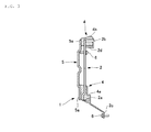
FIG. 3 is a side view of the damper module and the bracket illustrated inFIG. 1 ; -
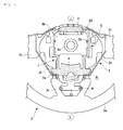
FIG. 4 is a plan view as seen from a back side, a state where the damper module and the bracket ofFIG. 1 are incorporated into the steering wheel, illustrating a preferred embodiment of a vehicle steering wheel according to the present invention; -
FIG. 5 is a perspective view as seen from above in a direction from the 2 o'clock position to the 8 o'clock position, of the vehicle steering wheel structure illustrated inFIG. 4 ; -
FIG. 6 is a perspective view as seen from below in the direction opposite to that ofFIG. 5 , of the vehicle steering wheel structure illustrated inFIG. 4 ; -
FIG. 7 is an enlarged view of a main part, illustrating a portion near a mounting portion of the bracket and the damper module illustrated inFIG. 1 ; and -
FIG. 8 is a cross-sectional view illustrating the state of a hole portion of a connection member that constitutes the damper module ofFIG. 1 . - Hereinafter, a preferred embodiment of a vehicle steering wheel structure according to the present invention will be described in detail with reference to the accompanying drawings.
FIGS. 1 to 3 illustrate adamper module 1 and abracket 2 attached to thedamper module 1.FIGS. 4 to 6 illustrate thebracket 2 in a state where thedamper module 1 is incorporated into an inner region R of arim portion 3a of asteering wheel 3. - As is well known, the
steering wheel 3 includes ashaft coupling portion 3d coupled to a steering shaft, anannular rim portion 3a that surrounds theshaft coupling portion 3d, and spokeportions 3c and a shaft couplingperipheral region 3b that connect therim portion 3a and theshaft coupling portion 3d. - The shaft coupling
peripheral region 3b is a portion that continuously extends from thespoke portion 3c to theshaft coupling portion 3d, and is not clearly distinguished from thespoke portion 3c in particular but means a region which includes an end portion of thespoke portion 3c and a periphery of theshaft coupling portion 3d and in which the end portion and the periphery are continuously connected. - In the illustrated example, the plurality of
spoke portions 3c that extends obliquely from therim portion 3a on the outer side toward theshaft coupling portion 3d on the inner side is formed to be integral with therim portion 3a. End portions of thespoke portions 3c are bonded to theshaft coupling portion 3d via the shaft couplingperipheral region 3b, whereby thesteering wheel 3 is formed. An airbag cushion and a horn device are incorporated into the inner region R of therim portion 3a that surrounds the shaft couplingperipheral region 3b. - The
damper module 1 and thebracket 2 are provided in the inner region R of therim portion 3a of thesteering wheel 3. Thedamper module 1 includes a plurality ofdamper masses 4 and aconnection member 5. Thedamper module 1 including thedamper masses 4 is provided in a range where thedamper module 1 is accommodated in a back cover (not illustrated) of thesteering wheel 3. - As is well known, the
damper mass 4 includes a metal member that serves as a weight. Thedamper mass 4 is formed by applying rubber that exhibits spring action and reduces noise caused by contact with other members to the metal member. For example, thedamper mass 4 is formed by superimposing a planar metal member and rubber and integrating the same by attaching the rubber to the metal member using vulcanized adhesion and damps vibration transferred from a vibrating source. Inexpensive cast iron is used as a material of the metal member, for example. Naturally, other metal materials can be also used. - The
damper masses 4 are arranged so as to be distributed in the inner region R of therim portion 3a, which has a small space due to the airbag cushion or the like incorporated therein. That is,small damper masses 4 obtained by dividing a large (heavy) damper mass necessary for obtaining required vibration damping effect into a plurality of pieces are individually disposed in a plurality of small spaces that can be secured in the inner region R of therim portion 3a. - Specifically, these
small damper masses 4 are arranged in an annular form on a side closer to therim portion 3a than theshaft coupling portion 3d so as to be distributed in the shaft couplingperipheral region 3b (in other words, along therim portion 3a) in order to effectively reduce vibration of thesteering wheel 3. When thedamper masses 4 are arranged in such an annular form, thesteering wheel 3 having satisfactory weight balance can be obtained. - In the illustrated example, the
damper masses 4 are arranged in the upper and lower parts (so-called "12 o'clock position" and "6 o'clock position" indicated by U and L in the drawings) of thesteering wheel 3 positioned in the neutral position where the wheels of the vehicle are in the straight direction. - The arrangement of the
damper masses 4 is not limited to the illustrated example, but may be arranged in the right and left portions ("3 o'clock position" and "9 o'clock position") in addition to these positions and may be disposed in the 3 o'clock position and 9 o'clock position instead of the 6 o'clock position and 12 o'clock position. Alternatively, the damper masses may be arranged at other positions. That is, the damper masses may be arranged at optional positions of the inner region R of therim portion 3a as long as the damper masses positioned at such positions can reduce vibration of thesteering wheel 3. Preferably, thedamper masses 4 are arranged at such positions that the damper masses are symmetrical (point-symmetrical or bilaterally symmetrical) about theshaft coupling portion 3d with respect to theshaft coupling portion 3d. - The
connection member 5 is disposed between the plurality of distributeddamper masses 4 so as to connect thesedamper masses 4. Theconnection member 5 is formed in a plate strip form using cast iron or steel materials, for example. A wide mountingportion 5a on which thedamper mass 4 is mounted is formed in a portion of theconnection member 5 connected to thedamper mass 4. - The
connection member 5 and thedamper mass 4 are connected according to various bonding methods such as mechanical bonding using bolts or the like or galvanized adhesion using rubber. In this manner, thedamper module 1 is formed as a single component by integrally connecting theconnection member 5 and the plurality ofdamper masses 4. - The
connection member 5 connects thedamper masses 4 to transfer vibration that theindividual damper masses 4 bear to theother damper masses 4. In this manner, the distributeddamper masses 4 complement vibration damping effect to share the vibration whereby a vibration reducing function of the plurality ofdamper masses 4 is secured. - Since the
connection member 5 has its own weight and also vibrates when vibration is transferred between thedamper masses 4, theconnection member 5 functions as a mass for damping vibration together with thedamper masses 4. Theconnection member 5 is coated with a damping member such as rubber, resin, or the like. By coating theconnection member 5 with a damping member such as rubber, it is possible to suppress noise generated when the connection member makes contact with other members. Theconnection member 5 may not be coated with rubber. - The
connection member 5 is formed in a closed ring form (endless annular form) in the shaft couplingperipheral region 3b (in other words, along therim portion 3a). Due to this, the plurality ofdamper masses 4 is arranged at an interval in the circumferential direction of theconnection member 5. In other words, the plurality ofdamper masses 4 is arranged in series in the inner region R of therim portion 3a with theconnection member 5 interposed. - By forming the
connection member 5 in a closed form, it is possible to improve rigidity and to secure an excellent vibration transferring effect using the lightweight connection member. Theconnection member 5 may has an open form with a disconnected portion rather than the closed form. On the other hand, theconnection member 5 may be formed as a plurality of plate strips having both ends rather than the ring form so that both ends of these plate strips are connected to thedamper masses 4. - A
hole 5b is formed in theconnection member 5 so that theconnection member 5 can be locked to thesteering wheel 3 with a relatively small slack in order to restrict unstable shaking of the connecteddamper masses 4 and theconnection member 5 itself. As illustrated inFIG. 8 , a pin, ascrew 7 or the like in which a head part having a larger outer diameter than the inner diameter of thehole 5b is formed at the upper end thereof is passed through thehole 5b and fixed to thesteering wheel 3. Due to this, it is possible to suppress large vertical motion of theconnection member 5 and to prevent the occurrence of unnecessary shaking. - As described above, the
connection member 5 and the plurality ofdamper masses 4 are connected to form thedamper module 1 as a single component, and thedamper module 1 is disposed in the inner region R of therim portion 3a. - The
damper module 1 and thebracket 2 are bonded in the mountingportions bracket 2 described later using a damping member that contains materials such as rubber or resin that are more flexible than normal metal. - The
bracket 2 is a belt-shaped member made from metal such as steel and has such outside dimensions that the bracket is accommodated in the inner region R of therim portion 3a. Thebracket 2 is formed in an approximately ring form so as to surround thedamper module 1. Thebracket 2 includes the mountingportions damper module 1 is mounted,attachment portions steering wheel 3, andbridge portions portions attachment portions - In the
bracket 2 of the illustrated example, thefirst attachment portion 2c that protrudes outward along thespoke portion 3c and thesecond attachment portion 2d that protrudes inward toward theshaft coupling portion 3d are formed at positions near thedamper masses 4 that are disposed at the "6 o'clock position" and the "12 o'clock position". Thefirst attachment portion 2c is attached and fixed at two positions to thespoke portion 3c byscrews 6, and thesecond setting step 2d is attached and fixed at two positions to the shaft couplingperipheral region 3b using screws 6. - In the
bracket 2, the first mountingportion 2a on which thedamper module 1 is mounted is formed near thefirst attachment portion 2c with acolumnar connecting portion 4a interposed, and thecolumnar connecting portion 4a is formed of a damping member such as a rubber and is provided in thedamper mass 4 positioned at the 6 o'clock position. The first mountingportion 2a is bonded to thedamper mass 4 by fitting simultaneously with thecolumnar connecting portion 4a or galvanized adhesion of rubber as illustrated inFIG. 7 . In this way, thedamper module 1 is integrally mounted on thebracket 2. - Moreover, in the
bracket 2, the second mountingportion 2b on which thedamper module 1 is mounted is formed near thesecond attachment portion 2d with acolumnar connecting portion 4b interposed, and thecolumnar connecting portion 4b is formed of a damping member such as a rubber and is provided in thedamper mass 4 positioned at the 12 o'clock position. Thesecond mounting portion 2b is also bonded to thedamper mass 4 by fitting simultaneously with thecolumnar connecting portion 4b or galvanized adhesion of rubber as illustrated inFIG. 7 . In this way, thedamper module 1 is integrally mounted. - The
bracket 2 on which thedamper module 1 is mounted is attached and fixed to thesteering wheel 3 by the first andsecond attachment portions damper module 1 is supported by thesteering wheel 3. - The
bridge portions damper module 1 and relative misalignment of theattachment portions portions damper module 1 is attached to thesteering wheel 3. - Next, the operation of the vehicle steering wheel structure according to the present embodiment will be described. First, assembling processes will be described. The
damper module 1 in which thedamper masses 4 are connected by theconnection member 5 is manufactured as a single component. Subsequently, thedamper module 1 is mounted on the mountingportions bracket 2 to manufacture thedamper module 1 to which thebracket 2 is attached. Subsequently, theattachment portions bracket 2 are attached and fixed to thesteering wheel 3 whereby thedamper module 1 is incorporated into the inner region R of therim portion 3a and is supported by thesteering wheel 3. - In the
damper module 1 supported by thesteering wheel 3, the total weight which is the sum of the weight of the plurality ofdamper masses 4 corresponds to the weight necessary for reducing vibration of thesteering wheel 3, and an efficient vibration damping effect can be secured. - Since the plurality of
damper masses 4 connected by theconnection member 5 acts integrally, it is possible to secure a higher vibration damping effect can be secured as compared to the conventional art in which distributed damper masses act individually. Since theconnection member 5 also works as an additional weight, it is possible to further improve the vibration damping effect. When theconnection member 5 is coated with rubber, the rubber also contributes to the vibration damping effect and the performance can be improved. - As described above, according to the vehicle steering wheel structure of the present embodiment, it is possible to allow the plurality of
damper masses 4 to function integrally by connecting thedamper masses 4 using theconnection member 5 while having a configuration in whichsmall damper masses 4 are arranged in a distributed manner, and to secure the same satisfactory vibration reducing effect as when a large (heavy) damper mass is provided. - Since the
damper masses 4 are just connected by theconnection member 5, it is possible to prevent an increase in the required installation space and to easily incorporate the damper masses in the narrow inner space of therim portion 3a. Thedamper masses 4 made from generally used materials can be used, and an increase in the cost resulting from material change can be prevented. - Since the
individual damper masses 4 are bonded to thebracket 2 by a damping member (rubber or the like), theintegrated damper module 1 connected by theconnection member 5 can be connected to thesteering wheel 3 in a wider range of areas, and the vibration damping performance can be improved. - The vehicle steering wheel structure includes the
bracket 2 that includes the mountingportions damper module 1 is mounted, and theattachment portions damper module 1 to thesteering wheel 3, and thebridge portions damper module 1 during attachment. Therefore, it is possible to easily attach thedamper module 1 to thesteering wheel 3. - Since the
damper masses 4 are arranged so as to be distributed in an annular form along therim portion 3a, it is possible to secure satisfactory weight balance of thesteering wheel 3 and to secure the vibration damping effect of thesteering wheel 3 in a well-balanced manner. - The
connection member 5 is formed in a closed ring form along therim portion 3a, and thedamper masses 4 are arranged at an interval in the circumferential direction of theconnection member 5. Therefore, by supporting thedamper module 1 on thesteering wheel 3, thedamper masses 4 can be immediately arranged to be distributed in an annular form along therim portion 3a, and the attachment operability can be improved. Moreover, it is possible to secure rigidity of theconnection member 5 and to secure an excellent vibration damping performance. - Since the
damper masses 4 are arranged in the upper and lower parts U and L of thesteering wheel 3 positioned in the neutral position, it is possible to suppress vibration of thesteering wheel 3 appropriately and effectively. Since thedamper module 1 is formed by integrating theconnection member 5 with thedamper masses 4, thedamper module 1 can be handled as a single component, and the attachment operability can be improved. Since thedamper module 1 and thebracket 2 are integrated, it is possible to further improve the attachment operability. - The vehicle steering wheel structure described hereinabove is a preferred example of the present invention, and other embodiments may be implemented or executed using various methods. Unless specific limiting description is provided in the specification of this application, the present invention is not limited to the specific shapes, sizes, configurations, arrangements, and the like of the components illustrated in the accompanying drawings. Further, the expressions and terminology used in the specification of this application are provided for descriptive purposes, and unless specific limiting description is provided, the present invention is not limited to these expressions and terminology.
Claims (7)
- A vehicle steering wheel structure comprising:a plurality of damper masses arranged so as to be distributed in an inner region of a rim portion of a steering wheel;a connection member that connects these damper masses; anda damper module disposed in the inner region of the rim portion.
- The vehicle steering wheel structure according to claim 1, further comprising:a bracket which includes a mounting portion on which the damper module is mounted, and an attachment portion attached and fixed to the steering wheel, and which allows the damper module to be supported by the steering wheel, whereinthe bracket and the damper module are connected by a damping member.
- The vehicle steering wheel structure according to claim 1 or 2, wherein
the connection member is coated with a damping member. - The vehicle steering wheel structure according to any one of claims 1 to 3, wherein
the damper masses are arranged so as to be distributed in an annular form along the rim portion. - The vehicle steering wheel structure according to any one of claims 1 to 4, wherein
the connection member is formed in a closed ring form along the rim portion, and
the damper masses are arranged at an interval in a circumferential direction of the connection member. - The vehicle steering wheel structure according to any one of claims 1 to 5, wherein
the damper masses are disposed above and below the steering wheel that is at a neutral position. - The vehicle steering wheel structure according to any one of claims 1 to 6, wherein
the damper module is formed by integrating the connection member and the damper masses.
Applications Claiming Priority (2)
| Application Number | Priority Date | Filing Date | Title |
|---|---|---|---|
| JP2011099467 | 2011-04-27 | ||
| PCT/JP2012/059980 WO2012147524A1 (en) | 2011-04-27 | 2012-04-12 | Structure of steering wheel for vehicle |
Publications (3)
| Publication Number | Publication Date |
|---|---|
| EP2703251A1 true EP2703251A1 (en) | 2014-03-05 |
| EP2703251A4 EP2703251A4 (en) | 2015-05-06 |
| EP2703251B1 EP2703251B1 (en) | 2017-05-31 |
Family
ID=47072046
Family Applications (1)
| Application Number | Title | Priority Date | Filing Date |
|---|---|---|---|
| EP12777624.3A Not-in-force EP2703251B1 (en) | 2011-04-27 | 2012-04-12 | Structure of steering wheel for vehicle |
Country Status (4)
| Country | Link |
|---|---|
| US (1) | US10422400B2 (en) |
| EP (1) | EP2703251B1 (en) |
| JP (1) | JP5639266B2 (en) |
| WO (1) | WO2012147524A1 (en) |
Families Citing this family (5)
| Publication number | Priority date | Publication date | Assignee | Title |
|---|---|---|---|---|
| US9581215B2 (en) * | 2013-03-15 | 2017-02-28 | Autoliv Asp, Inc. | Steering wheel vibration suppressors |
| JP6470884B2 (en) * | 2015-04-13 | 2019-02-13 | オートリブ ディベロップメント エービー | Steering wheel device |
| US11618501B2 (en) | 2019-02-08 | 2023-04-04 | Autoliv Development Ab | Vibration reduction structure for vehicle steering wheel |
| US11964720B2 (en) * | 2019-02-08 | 2024-04-23 | Autoliv Development Ab | Vibration-damping structure for vehicle steering wheel, and vehicle steering wheel device |
| DE102019211012A1 (en) * | 2019-07-25 | 2021-01-28 | Ford Global Technologies, Llc | Motor vehicle steering wheel with damping device |
Family Cites Families (14)
| Publication number | Priority date | Publication date | Assignee | Title |
|---|---|---|---|---|
| US6508343B2 (en) * | 2000-01-18 | 2003-01-21 | Honda Giken Kogyo Kabushiki Kaisha | Vibration damper |
| JP2002145075A (en) | 2000-11-06 | 2002-05-22 | Honda Motor Co Ltd | Steering wheel damping device |
| JP4171219B2 (en) * | 2001-02-19 | 2008-10-22 | 東海ゴム工業株式会社 | Vibration control device |
| US6817456B2 (en) * | 2001-03-30 | 2004-11-16 | Tokai Rubber Industries, Ltd. | Dynamic damper for steering system |
| JP3754317B2 (en) | 2001-04-26 | 2006-03-08 | 東洋ゴム工業株式会社 | Vibration isolator |
| JP2003040112A (en) | 2001-07-30 | 2003-02-13 | Tokai Rubber Ind Ltd | Dynamic damper device for steering |
| KR100792871B1 (en) * | 2001-12-18 | 2008-01-08 | 현대자동차주식회사 | Steering device for decreasing shimmy in vehicle |
| DE10393126D2 (en) * | 2002-09-06 | 2005-11-17 | Continental Teves Ag & Co Ohg | A steering handle for motor vehicles and method for detecting a physical quantity on a steering handle |
| JP2005036845A (en) * | 2003-07-17 | 2005-02-10 | Tokai Rubber Ind Ltd | Dynamic damper |
| JP5153526B2 (en) * | 2008-02-01 | 2013-02-27 | 本田技研工業株式会社 | Steering wheel vibration reduction structure |
| JP5005019B2 (en) * | 2009-11-23 | 2012-08-22 | 本田技研工業株式会社 | Steering wheel |
| JP2013071626A (en) * | 2011-09-28 | 2013-04-22 | Toyoda Gosei Co Ltd | Vibration damping structure for steering wheel |
| JP5765284B2 (en) * | 2012-03-30 | 2015-08-19 | 豊田合成株式会社 | Steering wheel damping structure |
| US9581215B2 (en) * | 2013-03-15 | 2017-02-28 | Autoliv Asp, Inc. | Steering wheel vibration suppressors |
-
2012
- 2012-04-12 US US14/114,031 patent/US10422400B2/en not_active Expired - Fee Related
- 2012-04-12 JP JP2013512003A patent/JP5639266B2/en not_active Expired - Fee Related
- 2012-04-12 EP EP12777624.3A patent/EP2703251B1/en not_active Not-in-force
- 2012-04-12 WO PCT/JP2012/059980 patent/WO2012147524A1/en not_active Ceased
Also Published As
| Publication number | Publication date |
|---|---|
| US20140174868A1 (en) | 2014-06-26 |
| US10422400B2 (en) | 2019-09-24 |
| EP2703251B1 (en) | 2017-05-31 |
| WO2012147524A1 (en) | 2012-11-01 |
| EP2703251A4 (en) | 2015-05-06 |
| JPWO2012147524A1 (en) | 2014-07-28 |
| JP5639266B2 (en) | 2014-12-10 |
Similar Documents
| Publication | Publication Date | Title |
|---|---|---|
| US9175739B2 (en) | Engine mount and power unit vibration damping support structure | |
| US9382961B2 (en) | Vibration damping device | |
| EP2703251B1 (en) | Structure of steering wheel for vehicle | |
| US20140175718A1 (en) | Torque rod | |
| CN110541909A (en) | Dynamic damper for vehicle | |
| US5971376A (en) | Liquid-enclosing type vibration isolating device | |
| US12044282B2 (en) | Powertrain mount with integrated tuned mass damper | |
| CN101454182A (en) | Air bag inflator vibration damper | |
| JP7348738B2 (en) | Engine mount | |
| JP6381345B2 (en) | Torsional rubber damper | |
| KR20150011646A (en) | coreless engine mount and manufacturing method thereof | |
| JP2009532650A (en) | Air bag inflator vibration damper | |
| KR101787413B1 (en) | A dynamic damper for a shaft | |
| CN107499301B (en) | Vacuum pump installing support assembly | |
| US8950737B2 (en) | Antivibration device | |
| KR102134821B1 (en) | Car Steering wheel Module Damper | |
| JP4124370B2 (en) | Dynamic damper and dynamic damper mounting structure | |
| JP2009196574A (en) | Suspension upper support and vehicle suspension mechanism using the same | |
| JP3754317B2 (en) | Vibration isolator | |
| JP2522643Y2 (en) | Drive system vibration damping device for automobiles | |
| JP6366444B2 (en) | Torque rod anti-vibration structure | |
| JP2002327792A (en) | Damping device | |
| JP7809622B2 (en) | Damper rod mount | |
| JP2002293247A (en) | Dynamic damper for steering | |
| CN120863729A (en) | Damping element, damping module, steering wheel device and vehicle |
Legal Events
| Date | Code | Title | Description |
|---|---|---|---|
| PUAI | Public reference made under article 153(3) epc to a published international application that has entered the european phase |
Free format text: ORIGINAL CODE: 0009012 |
|
| 17P | Request for examination filed |
Effective date: 20131118 |
|
| AK | Designated contracting states |
Kind code of ref document: A1 Designated state(s): AL AT BE BG CH CY CZ DE DK EE ES FI FR GB GR HR HU IE IS IT LI LT LU LV MC MK MT NL NO PL PT RO RS SE SI SK SM TR |
|
| DAX | Request for extension of the european patent (deleted) | ||
| REG | Reference to a national code |
Ref country code: DE Ref legal event code: R079 Ref document number: 602012033017 Country of ref document: DE Free format text: PREVIOUS MAIN CLASS: B62D0001100000 Ipc: B62D0007220000 |
|
| RA4 | Supplementary search report drawn up and despatched (corrected) |
Effective date: 20150408 |
|
| RIC1 | Information provided on ipc code assigned before grant |
Ipc: F16F 7/10 20060101ALI20150331BHEP Ipc: B62D 7/22 20060101AFI20150331BHEP |
|
| GRAP | Despatch of communication of intention to grant a patent |
Free format text: ORIGINAL CODE: EPIDOSNIGR1 |
|
| INTG | Intention to grant announced |
Effective date: 20161223 |
|
| GRAS | Grant fee paid |
Free format text: ORIGINAL CODE: EPIDOSNIGR3 |
|
| GRAA | (expected) grant |
Free format text: ORIGINAL CODE: 0009210 |
|
| AK | Designated contracting states |
Kind code of ref document: B1 Designated state(s): AL AT BE BG CH CY CZ DE DK EE ES FI FR GB GR HR HU IE IS IT LI LT LU LV MC MK MT NL NO PL PT RO RS SE SI SK SM TR |
|
| REG | Reference to a national code |
Ref country code: CH Ref legal event code: EP Ref country code: GB Ref legal event code: FG4D |
|
| REG | Reference to a national code |
Ref country code: AT Ref legal event code: REF Ref document number: 897174 Country of ref document: AT Kind code of ref document: T Effective date: 20170615 |
|
| REG | Reference to a national code |
Ref country code: IE Ref legal event code: FG4D |
|
| REG | Reference to a national code |
Ref country code: DE Ref legal event code: R096 Ref document number: 602012033017 Country of ref document: DE |
|
| REG | Reference to a national code |
Ref country code: NL Ref legal event code: MP Effective date: 20170531 |
|
| REG | Reference to a national code |
Ref country code: LT Ref legal event code: MG4D |
|
| REG | Reference to a national code |
Ref country code: AT Ref legal event code: MK05 Ref document number: 897174 Country of ref document: AT Kind code of ref document: T Effective date: 20170531 |
|
| PG25 | Lapsed in a contracting state [announced via postgrant information from national office to epo] |
Ref country code: LT Free format text: LAPSE BECAUSE OF FAILURE TO SUBMIT A TRANSLATION OF THE DESCRIPTION OR TO PAY THE FEE WITHIN THE PRESCRIBED TIME-LIMIT Effective date: 20170531 Ref country code: HR Free format text: LAPSE BECAUSE OF FAILURE TO SUBMIT A TRANSLATION OF THE DESCRIPTION OR TO PAY THE FEE WITHIN THE PRESCRIBED TIME-LIMIT Effective date: 20170531 Ref country code: NO Free format text: LAPSE BECAUSE OF FAILURE TO SUBMIT A TRANSLATION OF THE DESCRIPTION OR TO PAY THE FEE WITHIN THE PRESCRIBED TIME-LIMIT Effective date: 20170831 Ref country code: ES Free format text: LAPSE BECAUSE OF FAILURE TO SUBMIT A TRANSLATION OF THE DESCRIPTION OR TO PAY THE FEE WITHIN THE PRESCRIBED TIME-LIMIT Effective date: 20170531 Ref country code: GR Free format text: LAPSE BECAUSE OF FAILURE TO SUBMIT A TRANSLATION OF THE DESCRIPTION OR TO PAY THE FEE WITHIN THE PRESCRIBED TIME-LIMIT Effective date: 20170901 Ref country code: FI Free format text: LAPSE BECAUSE OF FAILURE TO SUBMIT A TRANSLATION OF THE DESCRIPTION OR TO PAY THE FEE WITHIN THE PRESCRIBED TIME-LIMIT Effective date: 20170531 Ref country code: AT Free format text: LAPSE BECAUSE OF FAILURE TO SUBMIT A TRANSLATION OF THE DESCRIPTION OR TO PAY THE FEE WITHIN THE PRESCRIBED TIME-LIMIT Effective date: 20170531 |
|
| PG25 | Lapsed in a contracting state [announced via postgrant information from national office to epo] |
Ref country code: NL Free format text: LAPSE BECAUSE OF FAILURE TO SUBMIT A TRANSLATION OF THE DESCRIPTION OR TO PAY THE FEE WITHIN THE PRESCRIBED TIME-LIMIT Effective date: 20170531 Ref country code: RS Free format text: LAPSE BECAUSE OF FAILURE TO SUBMIT A TRANSLATION OF THE DESCRIPTION OR TO PAY THE FEE WITHIN THE PRESCRIBED TIME-LIMIT Effective date: 20170531 Ref country code: IS Free format text: LAPSE BECAUSE OF FAILURE TO SUBMIT A TRANSLATION OF THE DESCRIPTION OR TO PAY THE FEE WITHIN THE PRESCRIBED TIME-LIMIT Effective date: 20170930 Ref country code: BG Free format text: LAPSE BECAUSE OF FAILURE TO SUBMIT A TRANSLATION OF THE DESCRIPTION OR TO PAY THE FEE WITHIN THE PRESCRIBED TIME-LIMIT Effective date: 20170831 Ref country code: SE Free format text: LAPSE BECAUSE OF FAILURE TO SUBMIT A TRANSLATION OF THE DESCRIPTION OR TO PAY THE FEE WITHIN THE PRESCRIBED TIME-LIMIT Effective date: 20170531 Ref country code: LV Free format text: LAPSE BECAUSE OF FAILURE TO SUBMIT A TRANSLATION OF THE DESCRIPTION OR TO PAY THE FEE WITHIN THE PRESCRIBED TIME-LIMIT Effective date: 20170531 |
|
| PG25 | Lapsed in a contracting state [announced via postgrant information from national office to epo] |
Ref country code: CZ Free format text: LAPSE BECAUSE OF FAILURE TO SUBMIT A TRANSLATION OF THE DESCRIPTION OR TO PAY THE FEE WITHIN THE PRESCRIBED TIME-LIMIT Effective date: 20170531 Ref country code: SK Free format text: LAPSE BECAUSE OF FAILURE TO SUBMIT A TRANSLATION OF THE DESCRIPTION OR TO PAY THE FEE WITHIN THE PRESCRIBED TIME-LIMIT Effective date: 20170531 Ref country code: DK Free format text: LAPSE BECAUSE OF FAILURE TO SUBMIT A TRANSLATION OF THE DESCRIPTION OR TO PAY THE FEE WITHIN THE PRESCRIBED TIME-LIMIT Effective date: 20170531 Ref country code: RO Free format text: LAPSE BECAUSE OF FAILURE TO SUBMIT A TRANSLATION OF THE DESCRIPTION OR TO PAY THE FEE WITHIN THE PRESCRIBED TIME-LIMIT Effective date: 20170531 Ref country code: EE Free format text: LAPSE BECAUSE OF FAILURE TO SUBMIT A TRANSLATION OF THE DESCRIPTION OR TO PAY THE FEE WITHIN THE PRESCRIBED TIME-LIMIT Effective date: 20170531 |
|
| PG25 | Lapsed in a contracting state [announced via postgrant information from national office to epo] |
Ref country code: SM Free format text: LAPSE BECAUSE OF FAILURE TO SUBMIT A TRANSLATION OF THE DESCRIPTION OR TO PAY THE FEE WITHIN THE PRESCRIBED TIME-LIMIT Effective date: 20170531 Ref country code: IT Free format text: LAPSE BECAUSE OF FAILURE TO SUBMIT A TRANSLATION OF THE DESCRIPTION OR TO PAY THE FEE WITHIN THE PRESCRIBED TIME-LIMIT Effective date: 20170531 Ref country code: PL Free format text: LAPSE BECAUSE OF FAILURE TO SUBMIT A TRANSLATION OF THE DESCRIPTION OR TO PAY THE FEE WITHIN THE PRESCRIBED TIME-LIMIT Effective date: 20170531 |
|
| REG | Reference to a national code |
Ref country code: DE Ref legal event code: R097 Ref document number: 602012033017 Country of ref document: DE |
|
| PLBE | No opposition filed within time limit |
Free format text: ORIGINAL CODE: 0009261 |
|
| STAA | Information on the status of an ep patent application or granted ep patent |
Free format text: STATUS: NO OPPOSITION FILED WITHIN TIME LIMIT |
|
| REG | Reference to a national code |
Ref country code: FR Ref legal event code: PLFP Year of fee payment: 7 |
|
| 26N | No opposition filed |
Effective date: 20180301 |
|
| PG25 | Lapsed in a contracting state [announced via postgrant information from national office to epo] |
Ref country code: SI Free format text: LAPSE BECAUSE OF FAILURE TO SUBMIT A TRANSLATION OF THE DESCRIPTION OR TO PAY THE FEE WITHIN THE PRESCRIBED TIME-LIMIT Effective date: 20170531 |
|
| PG25 | Lapsed in a contracting state [announced via postgrant information from national office to epo] |
Ref country code: MC Free format text: LAPSE BECAUSE OF FAILURE TO SUBMIT A TRANSLATION OF THE DESCRIPTION OR TO PAY THE FEE WITHIN THE PRESCRIBED TIME-LIMIT Effective date: 20170531 |
|
| REG | Reference to a national code |
Ref country code: CH Ref legal event code: PL |
|
| REG | Reference to a national code |
Ref country code: BE Ref legal event code: MM Effective date: 20180430 |
|
| REG | Reference to a national code |
Ref country code: IE Ref legal event code: MM4A |
|
| PG25 | Lapsed in a contracting state [announced via postgrant information from national office to epo] |
Ref country code: LU Free format text: LAPSE BECAUSE OF NON-PAYMENT OF DUE FEES Effective date: 20180412 |
|
| PG25 | Lapsed in a contracting state [announced via postgrant information from national office to epo] |
Ref country code: LI Free format text: LAPSE BECAUSE OF NON-PAYMENT OF DUE FEES Effective date: 20180430 Ref country code: BE Free format text: LAPSE BECAUSE OF NON-PAYMENT OF DUE FEES Effective date: 20180430 Ref country code: CH Free format text: LAPSE BECAUSE OF NON-PAYMENT OF DUE FEES Effective date: 20180430 |
|
| PG25 | Lapsed in a contracting state [announced via postgrant information from national office to epo] |
Ref country code: IE Free format text: LAPSE BECAUSE OF NON-PAYMENT OF DUE FEES Effective date: 20180412 |
|
| PGFP | Annual fee paid to national office [announced via postgrant information from national office to epo] |
Ref country code: GB Payment date: 20190430 Year of fee payment: 8 |
|
| PG25 | Lapsed in a contracting state [announced via postgrant information from national office to epo] |
Ref country code: MT Free format text: LAPSE BECAUSE OF NON-PAYMENT OF DUE FEES Effective date: 20180412 |
|
| PG25 | Lapsed in a contracting state [announced via postgrant information from national office to epo] |
Ref country code: TR Free format text: LAPSE BECAUSE OF FAILURE TO SUBMIT A TRANSLATION OF THE DESCRIPTION OR TO PAY THE FEE WITHIN THE PRESCRIBED TIME-LIMIT Effective date: 20170531 |
|
| PG25 | Lapsed in a contracting state [announced via postgrant information from national office to epo] |
Ref country code: PT Free format text: LAPSE BECAUSE OF FAILURE TO SUBMIT A TRANSLATION OF THE DESCRIPTION OR TO PAY THE FEE WITHIN THE PRESCRIBED TIME-LIMIT Effective date: 20170531 Ref country code: HU Free format text: LAPSE BECAUSE OF FAILURE TO SUBMIT A TRANSLATION OF THE DESCRIPTION OR TO PAY THE FEE WITHIN THE PRESCRIBED TIME-LIMIT; INVALID AB INITIO Effective date: 20120412 |
|
| PG25 | Lapsed in a contracting state [announced via postgrant information from national office to epo] |
Ref country code: CY Free format text: LAPSE BECAUSE OF FAILURE TO SUBMIT A TRANSLATION OF THE DESCRIPTION OR TO PAY THE FEE WITHIN THE PRESCRIBED TIME-LIMIT Effective date: 20170531 Ref country code: MK Free format text: LAPSE BECAUSE OF NON-PAYMENT OF DUE FEES Effective date: 20170531 |
|
| PG25 | Lapsed in a contracting state [announced via postgrant information from national office to epo] |
Ref country code: AL Free format text: LAPSE BECAUSE OF FAILURE TO SUBMIT A TRANSLATION OF THE DESCRIPTION OR TO PAY THE FEE WITHIN THE PRESCRIBED TIME-LIMIT Effective date: 20170531 |
|
| PGFP | Annual fee paid to national office [announced via postgrant information from national office to epo] |
Ref country code: DE Payment date: 20200429 Year of fee payment: 9 Ref country code: FR Payment date: 20200429 Year of fee payment: 9 |
|
| GBPC | Gb: european patent ceased through non-payment of renewal fee |
Effective date: 20200412 |
|
| PG25 | Lapsed in a contracting state [announced via postgrant information from national office to epo] |
Ref country code: GB Free format text: LAPSE BECAUSE OF NON-PAYMENT OF DUE FEES Effective date: 20200412 |
|
| REG | Reference to a national code |
Ref country code: DE Ref legal event code: R119 Ref document number: 602012033017 Country of ref document: DE |
|
| PG25 | Lapsed in a contracting state [announced via postgrant information from national office to epo] |
Ref country code: FR Free format text: LAPSE BECAUSE OF NON-PAYMENT OF DUE FEES Effective date: 20210430 Ref country code: DE Free format text: LAPSE BECAUSE OF NON-PAYMENT OF DUE FEES Effective date: 20211103 |