EP2703206A1 - In-vehicle display apparatus - Google Patents
In-vehicle display apparatus Download PDFInfo
- Publication number
- EP2703206A1 EP2703206A1 EP13182438.5A EP13182438A EP2703206A1 EP 2703206 A1 EP2703206 A1 EP 2703206A1 EP 13182438 A EP13182438 A EP 13182438A EP 2703206 A1 EP2703206 A1 EP 2703206A1
- Authority
- EP
- European Patent Office
- Prior art keywords
- frame
- display screen
- guide
- display panel
- longitudinal direction
- Prior art date
- Legal status (The legal status is an assumption and is not a legal conclusion. Google has not performed a legal analysis and makes no representation as to the accuracy of the status listed.)
- Granted
Links
Images






Classifications
-
- B—PERFORMING OPERATIONS; TRANSPORTING
- B60—VEHICLES IN GENERAL
- B60K—ARRANGEMENT OR MOUNTING OF PROPULSION UNITS OR OF TRANSMISSIONS IN VEHICLES; ARRANGEMENT OR MOUNTING OF PLURAL DIVERSE PRIME-MOVERS IN VEHICLES; AUXILIARY DRIVES FOR VEHICLES; INSTRUMENTATION OR DASHBOARDS FOR VEHICLES; ARRANGEMENTS IN CONNECTION WITH COOLING, AIR INTAKE, GAS EXHAUST OR FUEL SUPPLY OF PROPULSION UNITS IN VEHICLES
- B60K35/00—Instruments specially adapted for vehicles; Arrangement of instruments in or on vehicles
- B60K35/60—Instruments characterised by their location or relative disposition in or on vehicles
-
- B—PERFORMING OPERATIONS; TRANSPORTING
- B60—VEHICLES IN GENERAL
- B60K—ARRANGEMENT OR MOUNTING OF PROPULSION UNITS OR OF TRANSMISSIONS IN VEHICLES; ARRANGEMENT OR MOUNTING OF PLURAL DIVERSE PRIME-MOVERS IN VEHICLES; AUXILIARY DRIVES FOR VEHICLES; INSTRUMENTATION OR DASHBOARDS FOR VEHICLES; ARRANGEMENTS IN CONNECTION WITH COOLING, AIR INTAKE, GAS EXHAUST OR FUEL SUPPLY OF PROPULSION UNITS IN VEHICLES
- B60K35/00—Instruments specially adapted for vehicles; Arrangement of instruments in or on vehicles
- B60K35/20—Output arrangements, i.e. from vehicle to user, associated with vehicle functions or specially adapted therefor
- B60K35/29—Instruments characterised by the way in which information is handled, e.g. showing information on plural displays or prioritising information according to driving conditions
-
- B—PERFORMING OPERATIONS; TRANSPORTING
- B60—VEHICLES IN GENERAL
- B60K—ARRANGEMENT OR MOUNTING OF PROPULSION UNITS OR OF TRANSMISSIONS IN VEHICLES; ARRANGEMENT OR MOUNTING OF PLURAL DIVERSE PRIME-MOVERS IN VEHICLES; AUXILIARY DRIVES FOR VEHICLES; INSTRUMENTATION OR DASHBOARDS FOR VEHICLES; ARRANGEMENTS IN CONNECTION WITH COOLING, AIR INTAKE, GAS EXHAUST OR FUEL SUPPLY OF PROPULSION UNITS IN VEHICLES
- B60K35/00—Instruments specially adapted for vehicles; Arrangement of instruments in or on vehicles
- B60K35/20—Output arrangements, i.e. from vehicle to user, associated with vehicle functions or specially adapted therefor
- B60K35/21—Output arrangements, i.e. from vehicle to user, associated with vehicle functions or specially adapted therefor using visual output, e.g. blinking lights or matrix displays
- B60K35/213—Virtual instruments
-
- B—PERFORMING OPERATIONS; TRANSPORTING
- B60—VEHICLES IN GENERAL
- B60K—ARRANGEMENT OR MOUNTING OF PROPULSION UNITS OR OF TRANSMISSIONS IN VEHICLES; ARRANGEMENT OR MOUNTING OF PLURAL DIVERSE PRIME-MOVERS IN VEHICLES; AUXILIARY DRIVES FOR VEHICLES; INSTRUMENTATION OR DASHBOARDS FOR VEHICLES; ARRANGEMENTS IN CONNECTION WITH COOLING, AIR INTAKE, GAS EXHAUST OR FUEL SUPPLY OF PROPULSION UNITS IN VEHICLES
- B60K35/00—Instruments specially adapted for vehicles; Arrangement of instruments in or on vehicles
- B60K35/20—Output arrangements, i.e. from vehicle to user, associated with vehicle functions or specially adapted therefor
- B60K35/21—Output arrangements, i.e. from vehicle to user, associated with vehicle functions or specially adapted therefor using visual output, e.g. blinking lights or matrix displays
- B60K35/22—Display screens
-
- B—PERFORMING OPERATIONS; TRANSPORTING
- B60—VEHICLES IN GENERAL
- B60K—ARRANGEMENT OR MOUNTING OF PROPULSION UNITS OR OF TRANSMISSIONS IN VEHICLES; ARRANGEMENT OR MOUNTING OF PLURAL DIVERSE PRIME-MOVERS IN VEHICLES; AUXILIARY DRIVES FOR VEHICLES; INSTRUMENTATION OR DASHBOARDS FOR VEHICLES; ARRANGEMENTS IN CONNECTION WITH COOLING, AIR INTAKE, GAS EXHAUST OR FUEL SUPPLY OF PROPULSION UNITS IN VEHICLES
- B60K35/00—Instruments specially adapted for vehicles; Arrangement of instruments in or on vehicles
- B60K35/20—Output arrangements, i.e. from vehicle to user, associated with vehicle functions or specially adapted therefor
- B60K35/28—Output arrangements, i.e. from vehicle to user, associated with vehicle functions or specially adapted therefor characterised by the type of the output information, e.g. video entertainment or vehicle dynamics information; characterised by the purpose of the output information, e.g. for attracting the attention of the driver
-
- B—PERFORMING OPERATIONS; TRANSPORTING
- B60—VEHICLES IN GENERAL
- B60K—ARRANGEMENT OR MOUNTING OF PROPULSION UNITS OR OF TRANSMISSIONS IN VEHICLES; ARRANGEMENT OR MOUNTING OF PLURAL DIVERSE PRIME-MOVERS IN VEHICLES; AUXILIARY DRIVES FOR VEHICLES; INSTRUMENTATION OR DASHBOARDS FOR VEHICLES; ARRANGEMENTS IN CONNECTION WITH COOLING, AIR INTAKE, GAS EXHAUST OR FUEL SUPPLY OF PROPULSION UNITS IN VEHICLES
- B60K35/00—Instruments specially adapted for vehicles; Arrangement of instruments in or on vehicles
- B60K35/65—Instruments specially adapted for specific vehicle types or users, e.g. for left- or right-hand drive
- B60K35/658—Instruments specially adapted for specific vehicle types or users, e.g. for left- or right-hand drive the instruments being ergonomically adjustable to the user
-
- B—PERFORMING OPERATIONS; TRANSPORTING
- B60—VEHICLES IN GENERAL
- B60K—ARRANGEMENT OR MOUNTING OF PROPULSION UNITS OR OF TRANSMISSIONS IN VEHICLES; ARRANGEMENT OR MOUNTING OF PLURAL DIVERSE PRIME-MOVERS IN VEHICLES; AUXILIARY DRIVES FOR VEHICLES; INSTRUMENTATION OR DASHBOARDS FOR VEHICLES; ARRANGEMENTS IN CONNECTION WITH COOLING, AIR INTAKE, GAS EXHAUST OR FUEL SUPPLY OF PROPULSION UNITS IN VEHICLES
- B60K37/00—Dashboards
- B60K37/20—Dashboard panels
-
- H—ELECTRICITY
- H05—ELECTRIC TECHNIQUES NOT OTHERWISE PROVIDED FOR
- H05K—PRINTED CIRCUITS; CASINGS OR CONSTRUCTIONAL DETAILS OF ELECTRIC APPARATUS; MANUFACTURE OF ASSEMBLAGES OF ELECTRICAL COMPONENTS
- H05K5/00—Casings, cabinets or drawers for electric apparatus
- H05K5/0017—Casings, cabinets or drawers for electric apparatus with operator interface units
- H05K5/0018—Casings, cabinets or drawers for electric apparatus with operator interface units having an electronic display
-
- B—PERFORMING OPERATIONS; TRANSPORTING
- B60—VEHICLES IN GENERAL
- B60K—ARRANGEMENT OR MOUNTING OF PROPULSION UNITS OR OF TRANSMISSIONS IN VEHICLES; ARRANGEMENT OR MOUNTING OF PLURAL DIVERSE PRIME-MOVERS IN VEHICLES; AUXILIARY DRIVES FOR VEHICLES; INSTRUMENTATION OR DASHBOARDS FOR VEHICLES; ARRANGEMENTS IN CONNECTION WITH COOLING, AIR INTAKE, GAS EXHAUST OR FUEL SUPPLY OF PROPULSION UNITS IN VEHICLES
- B60K2360/00—Indexing scheme associated with groups B60K35/00 or B60K37/00 relating to details of instruments or dashboards
- B60K2360/18—Information management
- B60K2360/186—Displaying information according to relevancy
- B60K2360/1868—Displaying information according to relevancy according to driving situations
-
- B—PERFORMING OPERATIONS; TRANSPORTING
- B60—VEHICLES IN GENERAL
- B60K—ARRANGEMENT OR MOUNTING OF PROPULSION UNITS OR OF TRANSMISSIONS IN VEHICLES; ARRANGEMENT OR MOUNTING OF PLURAL DIVERSE PRIME-MOVERS IN VEHICLES; AUXILIARY DRIVES FOR VEHICLES; INSTRUMENTATION OR DASHBOARDS FOR VEHICLES; ARRANGEMENTS IN CONNECTION WITH COOLING, AIR INTAKE, GAS EXHAUST OR FUEL SUPPLY OF PROPULSION UNITS IN VEHICLES
- B60K2360/00—Indexing scheme associated with groups B60K35/00 or B60K37/00 relating to details of instruments or dashboards
- B60K2360/20—Optical features of instruments
-
- B—PERFORMING OPERATIONS; TRANSPORTING
- B60—VEHICLES IN GENERAL
- B60K—ARRANGEMENT OR MOUNTING OF PROPULSION UNITS OR OF TRANSMISSIONS IN VEHICLES; ARRANGEMENT OR MOUNTING OF PLURAL DIVERSE PRIME-MOVERS IN VEHICLES; AUXILIARY DRIVES FOR VEHICLES; INSTRUMENTATION OR DASHBOARDS FOR VEHICLES; ARRANGEMENTS IN CONNECTION WITH COOLING, AIR INTAKE, GAS EXHAUST OR FUEL SUPPLY OF PROPULSION UNITS IN VEHICLES
- B60K2360/00—Indexing scheme associated with groups B60K35/00 or B60K37/00 relating to details of instruments or dashboards
- B60K2360/20—Optical features of instruments
- B60K2360/27—Optical features of instruments using semi-transparent optical elements
- B60K2360/28—Optical features of instruments using semi-transparent optical elements for instruments which are not visible when inactive
-
- B—PERFORMING OPERATIONS; TRANSPORTING
- B60—VEHICLES IN GENERAL
- B60K—ARRANGEMENT OR MOUNTING OF PROPULSION UNITS OR OF TRANSMISSIONS IN VEHICLES; ARRANGEMENT OR MOUNTING OF PLURAL DIVERSE PRIME-MOVERS IN VEHICLES; AUXILIARY DRIVES FOR VEHICLES; INSTRUMENTATION OR DASHBOARDS FOR VEHICLES; ARRANGEMENTS IN CONNECTION WITH COOLING, AIR INTAKE, GAS EXHAUST OR FUEL SUPPLY OF PROPULSION UNITS IN VEHICLES
- B60K2360/00—Indexing scheme associated with groups B60K35/00 or B60K37/00 relating to details of instruments or dashboards
- B60K2360/60—Structural details of dashboards or instruments
- B60K2360/68—Features of instruments
- B60K2360/682—Arrangements to cover or hide instruments
-
- G—PHYSICS
- G01—MEASURING; TESTING
- G01D—MEASURING NOT SPECIALLY ADAPTED FOR A SPECIFIC VARIABLE; ARRANGEMENTS FOR MEASURING TWO OR MORE VARIABLES NOT COVERED IN A SINGLE OTHER SUBCLASS; TARIFF METERING APPARATUS; MEASURING OR TESTING NOT OTHERWISE PROVIDED FOR
- G01D11/00—Component parts of measuring arrangements not specially adapted for a specific variable
- G01D11/30—Supports specially adapted for an instrument; Supports specially adapted for a set of instruments
- G01D11/305—Panel mounting of instruments
Definitions
- the present invention relates to an in-vehicle display apparatus mounted on an instrument panel in a vehicle interior.
- an apparatus As an example of an in-vehicle display apparatus mounted on an instrument panel in a vehicle interior, an apparatus has been developed that can display vehicle-related information such as travel speed or engine speed on a display screen of a display panel and that can selectively display vehicle related information by moving an annular frame, displayed in front of the display screen, in the right-left direction.
- vehicle-related information such as travel speed or engine speed
- an annular frame is driven to reciprocate between a first display area and a second display area by a driving unit such as a motor.
- a specific type of vehicle-related information such as an image of a tachometer, is constantly displayed in a circular area surrounded by the annular frame.
- Other types of vehicle-related information such as images of a fuel gauge and an inlet/exhaust gas temperature gauge, are selectively displayed in other areas.
- an initial screen is displayed, that is, an image of a tachometer is displayed in a first display area of a display screen and other types of vehicle-related information, such as images of a fuel gauge and a coolant temperature gauge, are displayed in other areas.
- the frame stops at the first display area so as to surround the outer periphery of the image of the tachometer.
- An object of the present invention is to provide an in-vehicle display apparatus that can hide a frame that is movable in front of a display panel while light of a screen is off.
- An in-vehicle display apparatus includes a display panel including a rectangular display screen; a frame positioned in front of the display panel, the frame surrounding at least part of an outer periphery of an image displayed on the display panel; and a driving mechanism that drives the frame to reciprocate in a longitudinal direction of the display screen. At least part of the frame forms a rotatable frame that is rotatable around an axis extending in a lateral direction of the display screen.
- the driving mechanism moves the frame while the frame is in front of the display panel and in a parallel position in relation to the display screen.
- the rotatable frame is rotated on a side of the display panel in a longitudinal direction of the display panel and stored in a storage space.
- the frame that surrounds at least part of an outer periphery of the displayed image is movable in front of the display panel.
- at least part (rotatable frame) of the frame is rotated on a side of the display panel in the longitudinal direction of the display panel and stored in a storage space.
- the frame can be retracted from the front of the display screen that no longer displays images and has darkened, thereby realizing a design called the "dead front" design, in which the presence of the display panel is not perceived.
- the size of the entire in-vehicle display apparatus in the longitudinal direction can be prevented from increasing.
- the driving mechanism includes a motor, a screw shaft, which is driven to rotate by the motor, and an actuator, which linearly moves in the longitudinal direction of the display screen as the screw shaft rotates, and the actuator includes a guide mechanism that rotatably and pivotally supports the rotatable frame and that regulates an angle at which the rotatable frame rotates.
- the rotatable frame can be smoothly operated.
- the guide mechanism may be a guide rail including a horizontal portion, which extends parallel to the screw shaft, and a bent portion, which is continuous with an end of the horizontal portion, and the rotatable frame may include a guide protrusion that slides over the guide rail and the guide protrusion may be pressed against the guide rail by an urging force of a spring member.
- This configuration is preferable because the guide mechanism can be simply made with this configuration.
- the driving mechanism may include a motor, a timing belt, which is driven by the motor to rotate between a pair of pulleys, and an actuator, which is joined to the timing belt and moves along a guide shaft extending in a longitudinal direction of the display screen.
- the actuator may rotatably and pivotally support the rotatable frame.
- a guide mechanism may be provided to regulate an angle at which the rotatable frame rotates.
- the guide mechanism may be a guide groove including a horizontal portion, which extends parallel to the guide shaft, and a bent portion, which is continuous with an end of the horizontal portion, and the rotatable frame may include a guide protrusion that fits into the guide groove.
- This configuration is preferable because the guide mechanism can be simply made and the rotatable frame can be smoothly operated with this configuration.
- the frame may be an integrated annular member.
- the frame include a pair of semicircular decorative rings obtained by dividing an annular member into two parts along a line extending in the lateral direction of the display screen, the decorative rings being individually rotatable around axes extending in the lateral direction of the display screen, that the driving mechanism drive the pair of decorative rings to reciprocate toward and away from each other in the longitudinal direction of the display screen, and that the driving mechanism drive the decorative rings to rotate on both sides of the display panel in the longitudinal direction and store the decorative rings in storage spaces.
- vehicle related information can be stereoscopically and selectively displayed, for example, a specific type of vehicle related information displayed on the display screen may be surrounded by the annularly joined decorative rings, or two types of vehicle related information displayed at separate positions of the display screen are individually and partially surrounded by the decorative rings each forming a semicircular shape.
- the decorative rings are rotated on both sides of the display panel in the longitudinal direction of the display panel and stored in storage spaces.
- the decorative rings can be retracted from the display screen that no longer displays images and has darkened, thereby realizing a design called the "dead front" design, in which the presence of the display panel is not perceived. Furthermore, since the decorative rings are stored in the storage spaces while being in bent positions, the size of the in-vehicle display apparatus in the longitudinal direction can be prevented from increasing.
- the driving mechanism that drives the decorative rings to operate include a motor, a pair of screw shafts, which are driven to rotate by the motor, and a pair of actuators, which linearly move in the longitudinal direction of the display screen as the screw shafts rotate, that the decorative rings be rotatably and pivotally supported by the actuators, and that a guide mechanism be provided to regulate angles at which the decorative rings rotate.
- This configuration is preferable because the pair of decorative rings can be smoothly operated.
- the pair of screw shafts may be individually driven to rotate by motors.
- the pair of screw shafts may be jointed together via a gear in a center portion of the display panel in the longitudinal direction of the display panel so as to rotate in opposite directions. This configuration is preferable because the pair of decorative rings can be driven to operate by a single motor.
- the guide mechanism that regulates the angles at which the decorative rings rotate may include a guide rail including a horizontal portion, which extends parallel to the screw shafts, and a bent portion, which is continuous with an end of the horizontal portion, and each of the decorative rings may include a guide protrusion that slides over the guide rail and the guide protrusion may be pressed against the guide rail by an urging force of a spring member.
- This configuration is preferable because the guide mechanism can be simply made with this configuration.
- the frame may include a pair of semicircular members obtained by dividing an annular member into two parts along a line extending in the lateral direction of the display screen, one of the semicircular members may be a movable frame that moves while being in a parallel position in relation to the display screen, and the other semicircular member may be the rotatable frame rotatably and pivotally supported by the movable frame, the driving mechanism may drive the movable frame and the rotatable frame to reciprocate in the longitudinal direction of the display screen while the movable frame and the rotatable frame are annularly joined, and the rotatable frame may be rotated on a side of the display panel in the longitudinal direction of the display panel and stored in the storage space.
- the movable frame and the rotatable frame in front of the display panel by moving the movable frame and the rotatable frame in front of the display panel, a specific type of vehicle related information displayed on the display screen can be stereoscopically and selectively displayed by being surrounded by the annularly joined movable and rotatable frames.
- the rotatable frame is rotated on a side of the display panel in the longitudinal direction of the display panel and stored in a storage space.
- the frame can be retracted from the display screen that no longer displays images and has darkened, thereby realizing a design called the "dead front" design, in which the presence of the display panel is not perceived.
- the driving mechanism that drives the frames may include a motor, a timing belt, which is driven by the motor to rotate, and an actuator, which is joined to the timing belt and moves along a guide shaft extending in a longitudinal direction of the display screen, the movable frame may be securely fixed to the actuator and the rotatable frame may be rotatably joined to the actuator, and a guide mechanism may be provided to regulate an angle at which the rotatable frame rotates.
- This configuration is preferable because the movable frame and the rotatable frame can be smoothly operated.
- the guide mechanism that regulates the angle at which the rotatable frame rotates may be a guide groove including a horizontal portion, which extends parallel to the guide shaft, and a bent portion, which is continuous with an end of the horizontal portion, and the rotatable frame may include an engagement protrusion that fits into the guide groove. This configuration is preferable because the guide mechanism can be simply made with this configuration.
- the frame that surrounds at least part of an outer periphery of the displayed image is movable in front of the display panel.
- the frame can be retracted from the front of the display screen that no longer displays images and has darkened, thereby realizing a design called the "dead front" design, in which the presence of the display panel is not perceived.
- the size of the in-vehicle display apparatus in the longitudinal direction can be prevented from increasing.
- an in-vehicle display apparatus 1 is mounted on an instrument panel positioned in front of a driver's seat in a vehicle interior of a vehicle.
- the in-vehicle display apparatus 1 is covered by a panel cover 2 having a rectangular opening 2a.
- the in-vehicle display apparatus 1 mainly includes a base board 3, which is attached to an installation portion of the vehicle, a rectangular display panel 4, which is fixed to the base board 3 and for which a component such as an LCD or an organic EL is employed, a pair of decorative rings 5 and 6, which serve as frames, and a driving mechanism 7, which drives these decorative rings 5 and 6.
- a display screen 4a of the display panel 4 is visually perceived through the opening 2a of the panel cover 2.
- Various types of information related to the conditions of the vehicle are displayed on the display screen 4a, such as travel speed, engine speed, the remaining amount of fuel, the remaining battery life, the remaining amount of engine oil, and navigation information.
- the base board 3 has an erect support wall 3a, to which a pair of guide members 8 are fixed.
- the guide members 8 each have a guide groove 8a, which linearly extends along a long side of the display panel 4.
- a pair of guide rails 9 are fixed to the base board 3.
- the pair of guide members 8 and the pair of guide rails 9 are disposed parallel to each other with the display panel 4 interposed therebetween.
- the guide rails 9 each include a horizontal portion 9a, arcuate portions 9b, and bent portions 9c.
- the horizontal portion 9a extends in the longitudinal direction (X1-X2 direction) of the display screen 4a and the bent portions 9c extend from both ends of the horizontal portion 9a via the arcuate portions 9b in a direction orthogonal to horizontal portion 9a.
- the lower ends of the bent portions 9c are fixed to the base board 3.
- Three support stands 10 are mounted on the base board 3 so as to be aligned along the guide rails 9.
- a first screw shaft 11 is rotatably supported by left and center support stands 10 and a second screw shaft 12 is rotatably supported by center and right support stands 10.
- a gear 11a is securely fixed to a right end portion of the first screw shaft 11 and a gear 12a is securely fixed to a left end portion of the second screw shaft 12.
- These gears 11a and 12a mesh together in a center portion in the longitudinal direction of the display screen 4a.
- An actuator 13 is fitted around the first screw shaft 11 and an engagement protrusion 13a of the actuator 13 is engaged in a helical groove 11b of the first screw shaft 11.
- an actuator 14 is fitted around the second screw shaft 12 and an engagement protrusion 14a of the actuator 14 is engaged in a helical groove 12b of the second screw shaft 12.
- a motor 15 is attached to the right support stand 10.
- a gear 15a which is securely fixed to an output shaft of the motor 15, meshes with a gear 12c, which is securely fixed to a right end portion of the second screw shaft 12.
- a detection switch 16 is mounted on the center support stand 10. Starting points of the decorative rings 5 and 6 are detected on the basis of output signals from the detection switch 16.
- the detection switch 16 is positioned within a range in which the actuator 14 is movable. When the actuator 14 moves to a center portion of the display screen 4a along the second screw shaft 12, the detection switch 16 is turned on and outputs a switch signal.
- the pair of decorative rings 5 and 6 are semicircular components obtained by dividing one annular member into two parts along a line extending in a lateral direction (Y1-Y2 direction) of the display screen 4a.
- the decorative ring 5 on the left has a C shape and the decorative ring 6 on the right has an inverted C shape.
- the decorative ring 5 has swing pieces 5a and the decorative ring 6 has swing pieces 6a. These swing pieces 5a and 6a are L shaped and protrude toward long sides of the display panel 4.
- One of the swing pieces 5a and one of the swing pieces 6a are slidably and rotatably inserted into the guide grooves 8a of the corresponding guide members 8.
- the other swing piece 5a and the other swing piece 6a are rotatably and pivotally supported by the corresponding actuators 13 and 14, respectively. These swing pieces 5a and 6a have guide protrusions 5b and 6b, respectively.
- a torsion coil spring spring member
- each swing piece 5a or 6a and the corresponding actuator 13 or 14 and each guide protrusion 5b or 6b is slidably pressed against the corresponding guide rail 9 by an urging force of the torsion coil spring.
- the decorative rings 5 and 6 move within an area under the opening 2a of the panel cover 2 in the right-left direction while being in a parallel position in relation to the display screen 4a.
- the decorative rings 5 and 6 rotate downward approximately 45 degrees and are stored in storage spaces S on both sides of the display screen 4a while being in inclined positions.
- the above-mentioned driving mechanism 7 includes components such as the motor 15 and the actuators 13 and 14.
- both decorative rings 5 and 6 are used as frames.
- the entireties of the decorative rings 5 and 6 including the swing pieces 5a and 6a form rotatable frames that are rotatable around axes extending in the lateral direction of the display screen 4a.
- Figs. 11A to 11E an operation of the in-vehicle display apparatus 1 having the above-described configuration will be described.
- the pair of decorative rings 5 and 6 are retracted from the display screen 4a and are stored in the storage spaces S on both right and left sides of the display panel 4, as illustrated in Fig. 11A .
- the "dead front" design in which the presence of the display panel 4 is not perceived until the power is turned on, is realized.
- the decorative rings 5 and 6 are stored in the storage spaces S while being in the inclined positions, in which the outer sides of the decorative rings 5 and 6 are inclined downward, as a result of the guide protrusions 5b and 6b coming into contact with the upper end portions of the bent portions 9c of the guide rails 9.
- the dimensions of the storage spaces S in the right-left direction (X1-X2 direction) can be reduced and, accordingly, the size of the whole in-vehicle display apparatus 1 in the longitudinal direction can be reduced.
- the detection switch 16 When the decorative rings 5 and 6 arrive at a center portion of the display screen 4a in this manner, the detection switch 16 is turned on by the right actuator 14 and thus the motor 15 temporarily stops in response to an output signal from the detection switch 16. Consequently, the decorative rings 5 and 6 stop in the center portion of the display screen 4a and thus results of system check such as the states of the engine oil or battery are displayed on areas of the display screen 4a outside of the decorative rings 5 and 6 as an initial screen, as illustrated in Fig. 11C .
- the guide protrusions 5b and 6b are in contact with inner end portions of the horizontal portions 9a of the guide rails 9.
- the pair of decorative rings 5 and 6 are joined together in the center portion of the display screen 4a while being in the horizontal positions and form one annular member.
- vehicle related information can be stereoscopically and selectively displayed.
- vehicle related information can be highlighted by being separated from the surroundings.
- Fig. 11D while engine speed and travel speed are displayed on the display screen 4a, if the decorative rings 5 and 6 are stopped at outer peripheral positions of the display areas displaying engine speed and travel speed, the areas of the display screen 4a displaying vehicle related information (such as engine speed or travel speed) can be highlighted by being separated from the surroundings.
- Fig. 11D while engine speed and travel speed are displayed on the display screen 4a, if the decorative rings 5 and 6 are stopped at outer peripheral positions of the display areas displaying engine speed and travel speed, the areas of the display screen 4a displaying vehicle related information (such as engine speed or travel speed) can be highlighted by being separated from the surroundings.
- vehicle related information can be stereoscopically and selectively displayed, for example, a specific type of vehicle related information displayed on the display screen 4a of the display panel 4 is surrounded by the annularly joined decorative rings 5 and 6, or two types of vehicle related information displayed on the display screen 4a are individually and partially surrounded by the corresponding decorative rings 5 and 6.
- the engine (or accessories) is off and the display panel 4 is off, these decorative rings 5 and 6 are rotated on both sides of the display panel 4 in the longitudinal direction and stored in the storage spaces S.
- the decorative rings 5 and 6 can be retracted from the front of the display screen 4a that no longer displays images and becomes dark, thereby realizing a design called the "dead front" design, in which the presence of the display panel 4 is not perceived. Furthermore, since the decorative rings 5 and 6 are stored in the storage spaces S while being in bent and inclined positions, the size of the entire in-vehicle display apparatus 1 in the longitudinal direction can be prevented from increasing.
- the driving mechanism 7, which drives the decorative rings 5 and 6 to reciprocate toward and away from each other includes the motor 15, the first and second screw shafts 11 and 12, which are driven to rotate by the motor 15, and the pair of actuators 13 and 14, which linearly move in the longitudinal direction of the display screen 4a as the screw shafts 11 and 12 rotate.
- the decorative rings 5 and 6 are rotatably and pivotally supported by the actuators 13 and 14 and the guide protrusions 5b and 6b of the decorative rings 5 and 6 are caused to slide over the guide rails 9 (guide mechanisms).
- the angles at which the decorative rings 5 and 6 rotate are regulated and the decorative rings 5 and 6 can operate smoothly.
- the pair of decorative rings 5 and 6 can be driven by a single motor 15 to reciprocate toward and away from each other.
- the entirety of the driving mechanism 7 can have a simple configuration, leading to space saving.
- the guide rails 9 are used as guide mechanisms that regulate the angles at which the decorative rings 5 and 6 rotate.
- the guide rails 9 each have the horizontal portion 9a, which extends parallel with the corresponding screw shaft 11 or 12, and the bent portions 9c, which extend from the ends of the horizontal portion 9a via the arcuate portions 9b in the direction perpendicular to the horizontal portion 9a.
- the guide protrusions 5b and 6b of the decorative rings 5 and 6 are pressed against the guide rails 9 by the urging force of torsion coil springs (spring members).
- torsion coil springs spring members
- Guide grooves having a shape similar to the guide rails 9 are also employable as guide mechanisms and the guide protrusions 5b and 6b may be inserted into the grooves so that the angles at which the decorative rings 5 and 6 rotate are regulated. In this case, spring members may be omitted.
- the screw shafts 11 and 12 are driven to rotate in opposite directions by a single motor 15.
- the first and second screw shafts 11 and 12 may be individually driven to rotate by two motors.
- the pair of decorative rings 5 and 6 can be made movable from one end to the opposite end of the display screen 4a.
- the decorative rings 5 and 6 can be annularly joined at any desired position, not only in the center portion of the display screen 4a.
- the pair of decorative rings 5 and 6, obtained by dividing an annular member into two parts along a line extending in the lateral direction of the display screen 4a, serve as frames and the decorative rings 5 and 6 are caused to reciprocate toward and away from each other in the longitudinal direction of the display screen 4a.
- a frame may be formed as an integrated annular member that is not divided into two parts. This frame may be caused to reciprocate in the longitudinal direction of the display screen 4a while being in a horizontal position and may be rotated on a side of the display panel 4 in the longitudinal direction of the display panel 4 and stored in a storage space S.
- a driving mechanism that actuates the frame includes a motor, a screw shaft, which is driven to rotate by the motor, and an actuator, which linearly moves in the longitudinal direction of the display screen 4a as the screw shaft rotates.
- the frame may be rotatably and pivotally supported by the actuator and a guide mechanism that regulates the angle at which the frame rotates may be provided.
- the guide mechanism may be a guide rail that includes a horizontal portion, which extends parallel to the screw shaft, and a bent portion, which is continuous with one end of the horizontal portion.
- the frame may have a guide protrusion that slides over the guide rail. The guide protrusion may be pressed against the guide rail by the urging force of a spring member.
- An in-vehicle display apparatus 20 mainly includes a base board 21, which is attached to an installation portion of the vehicle, a rectangular display panel 22, which is fixed to the base board 21 and for which a component such as an LCD or an organic EL is employed, first and second decorative rings 23 and 24, which serve as frames, and a pair of driving mechanisms 25, which drive these decorative rings 23 and 24.
- a display screen 22a of the display panel 22 is visually perceived through an opening of a panel cover, which is not illustrated.
- the base board 21 has a pair of erect support walls 21a and 21b.
- the support walls 21a and 21b are parallel to each other and face each other with the display panel 22 interposed therebetween.
- one of the support walls 21a is drawn by a chain double-dashed line.
- Guide shafts 26 are fixed to inner surfaces of the support walls 21a and 21b.
- the guide shafts 26 linearly extend along the long sides of the display panel 22.
- Each of the support walls 21a and 21b has two guide grooves 27.
- Each guide groove 27 has a horizontal portion 27a, an arcuate portion 27b, and a bent portion 27c.
- the horizontal portion 27a extends in the longitudinal direction (X1-X2 direction of Fig. 12 ) of the display screen 22a and the bent portion 27c extends in a direction perpendicular to the horizontal portion 27a from an end portion of the horizontal portion 27a via the arcuate portion 27b.
- a first timing belt 29 is wound around four of the six pulleys disposed near the lower support wall 21a and a second timing belt 30 is wound around remaining two of the six pulleys disposed near the upper support wall 21b.
- a first actuator 31 is securely fixed to the first timing belt 29.
- the first actuator 31 is slidably fitted around one of the guide shafts 26.
- a second actuator 32 is securely fixed to the second timing belt 30.
- the second actuator 32 is slidably fitted around the other guide shaft 26.
- First and second motors 33 and 34 are mounted on the base board 21.
- a worm 33a securely fixed to an output shaft of the first motor 33 meshes with a worm wheel 28a attached to a nearby pulley 28.
- a worm 34a securely fixed to an output shaft of the second motor 34 meshes with a worm wheel 28b attached to a nearby pulley 28.
- Detection switches 35 and 36 are attached to the inner surfaces of the support walls 21a and 21b. Starting points of the first and second decorative rings 23 and 24 are detected on the basis of output signals from the detection switches 35 and 36. Specifically, the detection switch 35 is positioned within a range in which the first actuator 31 is movable. When the first actuator 31 moves rightward (in the X2 direction) from the left edge of the display screen 22a and becomes separated from the detection switch 35, a contact of the detection switch 35 is subjected to a switching operation so that the detection switch 35 outputs a switch signal.
- the detection switch 36 is positioned within a range in which the second actuator 32 is movable.
- the first decorative ring 23 includes two semicircular components obtained by dividing an annular member into two parts along a line extending in the lateral direction (Y1-Y2 direction of Fig. 12 ) of the display screen 22a, that is, a first movable frame 37, which is an inverted C shaped component disposed on the right side, and a first rotatable frame 38, which is a C shaped component disposed on the left side.
- the first movable frame 37 includes protrusion pieces 37a that protrude toward the long sides of the display panel 22.
- One of the protrusion pieces 37a is fixed to the first actuator 31 and the other protrusion piece 37a is slidably fitted around the corresponding guide shaft 26.
- the first rotatable frame 38 has swing pieces 38a, which are L shaped and protrude toward the long sides of the display panel 22. These swing pieces 38a are rotatably and pivotally supported by the protrusion pieces 37a of the first movable frame 37. Furthermore, each swing piece 38a has an engagement pin 38b, which is slidably inserted into the corresponding guide groove 27 formed in the support wall 21a or 21b.
- the first timing belt 29 is driven by the first motor 33 to rotate around the pulleys 28 and the first actuator 31 linearly moves in the axis direction of the guide shafts 26 (in the X1-X2 direction of Fig. 12 )
- the first movable frame 37 fixed to the first actuator 31 and the first rotatable frame 38 pivotally supported by the protrusion pieces 37a of the first rotatable frame 37 move together in an integrated manner in front of the display screen 22a.
- the first rotatable frame 38 changes its position in accordance with the positions of the engagement pins 38b with respect to the guide grooves 27 during sliding.
- the first movable frame 37 and the first rotatable frame 38 move in the right-left direction while being in a parallel position in relation to the display screen 22a.
- the engagement pins 38b slide over the arcuate portions 27b of the guide grooves 27 toward the bent portions 27c only the first rotatable frame 38 rotates downward approximately 45 degrees and is stored in a storage space S on a side of the display screen 22a while being in an inclined position.
- the second decorative ring 24 includes two semicircular components obtained by dividing an annular member into two parts along a line extending in the lateral direction of the display screen 22a, that is, a second movable frame 39, which is a C shaped component disposed on the left side, and a second rotatable frame 40, which is an inverted C shaped component disposed on the right side.
- the second movable frame 39 includes protrusion pieces 39a that protrude toward the long sides of the display panel 22.
- One of the protrusion pieces 39a is slidably fitted around the corresponding guide shaft 26 and the other protrusion piece 39a is fixed to the second actuator 32.
- the second rotatable frame 40 has swing pieces 40a, which are L shaped and protrude toward the long sides of the display panel 22. These swing pieces 40a are rotatably and pivotally supported by the protrusion pieces 39a of the second movable frame 39. Furthermore, each swing piece 40a has an engagement pin 40b, which is slidably inserted into the corresponding guide groove 27 formed in the support wall 21a or 21b.
- the second timing belt 30 is driven by the second motor 34 to rotate around the pulleys 28 and the second actuator 32 linearly moves in the axis direction of the guide shafts 26, the second movable frame 39 fixed to the second actuator 32 and the second rotatable frame 40 pivotally supported by the protrusion pieces 39a of the second rotatable frame 39 move together in an integrated manner in front of the display screen 22a. Then, the second rotatable frame 40 changes its position in accordance with the positions of the engagement pins 40b with respect to the guide grooves 27 during sliding.
- the second movable frame 39 and the second rotatable frame 40 move in the right-left direction while being in a parallel position in relation to the display screen 22a.
- the engagement pins 40b slide over the arcuate portions 27b of the guide grooves 27 toward the bent portions 27c only the second rotatable frame 40 rotates downward approximately 45 degrees and is stored in a storage space S on a side of the display screen 22a while being in an inclined position.
- a driving mechanism 25 that drives the first decorative ring 23 includes components such as the first motor 33, the first timing belt 29, the first actuator 31, and the swing pieces 38a.
- a driving mechanism 25 that drives the second decorative ring 24 includes components such as the second motor 34, the second timing belt 30, the second actuator 32, and the swing pieces 40a.
- the in-vehicle display apparatus 20 includes the first and second decorative rings 23 and 24 as frames that are individually driven by the driving mechanisms 25.
- movable frames first and second movable frames 37 and 39
- rotatable frames first and second rotatable frames 38 and 40
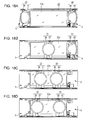
- Figs. 18A to 18D an operation of the in-vehicle display apparatus 20 according to the present embodiment will be described.
- the first and second decorative rings 23 and 24 are retracted from the front of the display screen 22a and are stored in the storage spaces S on both right and left sides of the display panel 22, as illustrated in Fig. 18A .
- the "dead front" design in which the presence of the display panel 22 is not perceived until the power is turned on, is realized.
- the first and second movable frames 37 and 39 of the first and second decorative rings 23 and 24 are stored in the storage spaces S while being in the horizontal positions, in which the decorative rings 23 and 24 are parallel to the display screen 22a, whereas the first and second rotatable frames 38 and 40 are stored in the storage spaces S while being in the inclined positions, in which the outer sides of the rotatable frames 38 and 40 are inclined downward, as a result of the engagement pins 38b and 40b being engaged with the lower end portions of the bent portions 27c of the corresponding guide grooves 27.
- the dimensions of the storage spaces S in the right-left direction (X1-X2 direction) can be reduced further than in the case where the entireties of the first and second decorative rings 23 and 24 are stored in the storage spaces S while being in the horizontal positions. Accordingly, the size of the whole in-vehicle display apparatus 1 in the longitudinal direction can be reduced.
- the first motor 33 and/or the second motor 34 start rotating forward or backward and then the first actuator 31 and/or the second actuator 32 start moving linearly in the axis direction of the corresponding guide shaft 26.
- the first actuator 31 starts moving from the outer side toward the inner side (in the X2 direction) along the axis of the corresponding guide shaft 26. Consequently, the first decorative ring 23 that has been stored in the left storage space S appears in front of the display screen 22a, as illustrated in Fig. 18B .
- the positions at which the engagement pins 38b become engaged with the guide grooves 27 change from the bent portions 27c to the horizontal portions 27a via the arcuate portions 27b as the first actuator 31 moves.
- the first rotatable frame 38 changes its position from the inclined position to the horizontal position by rotating approximately 45 degrees and moves together with the first movable frame 37 in front of the display screen 22a while keeping in the horizontal position.
- the first decorative ring 23 can be stopped at the center portion of the display screen 22a so that results of system check, such as the states of the engine oil or battery, are displayed on the display screen 22a in an area surrounded by the first decorative ring 23 as an initial screen.
- the first and second decorative rings 23 and 24 may be stopped near the center portion of the display screen 22a such that the vehicle related information, such as engine speed or travel speed, may be individually displayed on the display screen 22a in areas surrounded by the first and second decorative rings 23 and 24.
- the vehicle related information such as engine speed or travel speed
- the first and second decorative rings 23 and 24 may be stopped at right and left positions separated from each other on the display screen 22a so that a different type of vehicle related information is displayed in an area of the display screen 22a interposed between the first decorative ring 23 and the second decorative ring 24. Still alternatively, when the display screen 22a is switched to a navigation mode, by moving the first and second decorative rings 23 and 24 to the outside of the display screen 22a and storing the decorative rings 23 and 24 in the storage spaces S, the entirety of the display screen 22a can be used as, for example, a navigation screen, i.e., full screen display is achieved.
- the in-vehicle display apparatus 20 can stereoscopically and selectively display vehicle related information by moving the first decorative ring 23 and the second decorative ring 24 in the right-left direction in front of the display panel 22, specifically, a specific type of vehicle related information displayed on the display screen 22a of the display panel 22 is annularly surrounded by the decorative ring 23 or 24 or two types of vehicle related information displayed on the display screen 22a are individually surrounded by both decorative rings 23 and 24.
- the first and second decorative rings 23 and 24 are stored in the storage spaces S on both sides of the display panel 22 in the longitudinal direction.
- the decorative rings 23 and 24 can be retracted from the front of the display screen 22a that no longer displays images and becomes dark, thereby realizing a design called the "dead front" design, in which the presence of the display panel 22 is not perceived.
- the first decorative ring 23 includes the semicircular first movable frame 37 and the semicircular first rotatable frame 38, which are joined together such that the first rotatable frame 38 is rotatable with respect to the first movable frame 37
- the second decorative ring 24 includes the semicircular second movable frame 39 and the semicircular second rotatable frame 40, which are joined together such that the second rotatable frame 40 is rotatable with respect to the second movable frame 39. Since the first rotatable frame 38 and the second rotatable frame 40 are stored in the storage spaces S while being in the inclined positions, the dimensions of the entire in-vehicle display apparatus 20 in the longitudinal direction and the thickness direction can be prevented from increasing.
- the driving mechanism 25 for driving the first decorative ring 23 includes the first motor 33, the first timing belt 29, which is driven to rotate by the first motor 33, and the first actuator 31, which is joined to the first timing belt 29 and moves in the axis direction of the guide shafts 26.
- the first movable frame 37 is securely fixed to the first actuator 31, the first rotatable frame 38 is rotatably joined to the first actuator 31, and the engagement pins 38b of the first rotatable frame 38 are inserted into the guide grooves 27 (guide mechanisms) so that the angle at which the first rotatable frame 38 rotates is regulated.
- the first movable frame 37 and the first rotatable frame 38 can operate smoothly.
- the driving mechanism 25 for driving the second decorative ring 24 includes the second motor 34, the second timing belt 30, which is driven to rotate by the second motor 34, and the second actuator 32, which is joined to the second timing belt 30 and moves in the axis direction of the guide shafts 26.
- the second movable frame 39 is securely fixed to the second actuator 32, the second rotatable frame 40 is rotatably joined to the second actuator 32, and the engagement pins 40b of the second rotatable frame 40 are inserted into the guide grooves 27 (guide mechanisms) so that the angle at which the second rotatable frame 40 rotates is regulated.
- the second movable frame 39 and the second rotatable frame 40 can operate smoothly.
- the guide grooves 27 are used as guide mechanisms that regulate the angles at which the first and second rotatable frames 38 and 40 rotate.
- Each guide groove 27 has the horizontal portion 27a, which extends parallel to the corresponding guide shaft 26, and the bent portion 27c, which extends in the direction perpendicular to the horizontal portion 27a from one end of the horizontal portion 27a via the arcuate portion 27b.
- the engagement pins 38b and 40b of the swing pieces 38a and 40a of the first and second rotatable frames 38 and 40 are slidably fitted into the guide grooves 27.
- the guide mechanism can be simply made with this configuration.
- first decorative ring 23 and the second decorative ring 24 are used.
- first decorative ring 23 or the second decorative ring 24 may be omitted and only one frame may be moved in the right-left direction in front of the display panel 22.
Landscapes
- Engineering & Computer Science (AREA)
- Chemical & Material Sciences (AREA)
- Combustion & Propulsion (AREA)
- Transportation (AREA)
- Mechanical Engineering (AREA)
- Microelectronics & Electronic Packaging (AREA)
- Fittings On The Vehicle Exterior For Carrying Loads, And Devices For Holding Or Mounting Articles (AREA)
- Indicating Measured Values (AREA)
Abstract
Description
- The present invention relates to an in-vehicle display apparatus mounted on an instrument panel in a vehicle interior.
- As an example of an in-vehicle display apparatus mounted on an instrument panel in a vehicle interior, an apparatus has been developed that can display vehicle-related information such as travel speed or engine speed on a display screen of a display panel and that can selectively display vehicle related information by moving an annular frame, displayed in front of the display screen, in the right-left direction. For example, in an in-vehicle display apparatus described
US 7,382,234 , an annular frame is driven to reciprocate between a first display area and a second display area by a driving unit such as a motor. A specific type of vehicle-related information, such as an image of a tachometer, is constantly displayed in a circular area surrounded by the annular frame. Other types of vehicle-related information, such as images of a fuel gauge and an inlet/exhaust gas temperature gauge, are selectively displayed in other areas. - In such an in-vehicle display apparatus, when the display panel is turned on as a result of turning an engine (or accessories) on, an initial screen is displayed, that is, an image of a tachometer is displayed in a first display area of a display screen and other types of vehicle-related information, such as images of a fuel gauge and a coolant temperature gauge, are displayed in other areas. Here, the frame stops at the first display area so as to surround the outer periphery of the image of the tachometer. From this state, when the driving unit is operated to move the frame from the first display area to the second display area, an image of the tachometer is displayed in the second display area and another type of vehicle-related information, such as an image of an engine oil gauge instead of a fuel gauge, is displayed in another area.
- However, in the above-described existing in-vehicle display apparatus, when the engine (or accessories) is off and the display panel is off, only the annular frame that is in a stationary state appears in front of the display screen that no longer displays images and has darkened. Since this frame is visually perceived as floating over the dark screen, the frame impairs the appearance of the display apparatus.
- An object of the present invention is to provide an in-vehicle display apparatus that can hide a frame that is movable in front of a display panel while light of a screen is off.
- The object is solved by the features of the independent claims. Further embodiments and aspects are defined in the dependent claims.
- An in-vehicle display apparatus according to an aspect of the invention includes a display panel including a rectangular display screen; a frame positioned in front of the display panel, the frame surrounding at least part of an outer periphery of an image displayed on the display panel; and a driving mechanism that drives the frame to reciprocate in a longitudinal direction of the display screen. At least part of the frame forms a rotatable frame that is rotatable around an axis extending in a lateral direction of the display screen. The driving mechanism moves the frame while the frame is in front of the display panel and in a parallel position in relation to the display screen. The rotatable frame is rotated on a side of the display panel in a longitudinal direction of the display panel and stored in a storage space.
- In the in-vehicle display apparatus having the above-described configuration, the frame that surrounds at least part of an outer periphery of the displayed image is movable in front of the display panel. When the engine (or accessories) is off and the display panel is off, at least part (rotatable frame) of the frame is rotated on a side of the display panel in the longitudinal direction of the display panel and stored in a storage space. Thus, the frame can be retracted from the front of the display screen that no longer displays images and has darkened, thereby realizing a design called the "dead front" design, in which the presence of the display panel is not perceived. Furthermore, since at least part of the frame is stored in the storage space while being in a rotated position, the size of the entire in-vehicle display apparatus in the longitudinal direction can be prevented from increasing.
- In an embodiment of the in-vehicle display apparatus, the driving mechanism includes a motor, a screw shaft, which is driven to rotate by the motor, and an actuator, which linearly moves in the longitudinal direction of the display screen as the screw shaft rotates, and the actuator includes a guide mechanism that rotatably and pivotally supports the rotatable frame and that regulates an angle at which the rotatable frame rotates.
- Thus, the rotatable frame can be smoothly operated.
- Here, the guide mechanism may be a guide rail including a horizontal portion, which extends parallel to the screw shaft, and a bent portion, which is continuous with an end of the horizontal portion, and the rotatable frame may include a guide protrusion that slides over the guide rail and the guide protrusion may be pressed against the guide rail by an urging force of a spring member. This configuration is preferable because the guide mechanism can be simply made with this configuration.
- According to another embodiment, the driving mechanism may include a motor, a timing belt, which is driven by the motor to rotate between a pair of pulleys, and an actuator, which is joined to the timing belt and moves along a guide shaft extending in a longitudinal direction of the display screen. The actuator may rotatably and pivotally support the rotatable frame. A guide mechanism may be provided to regulate an angle at which the rotatable frame rotates.
- In this case, the guide mechanism may be a guide groove including a horizontal portion, which extends parallel to the guide shaft, and a bent portion, which is continuous with an end of the horizontal portion, and the rotatable frame may include a guide protrusion that fits into the guide groove. This configuration is preferable because the guide mechanism can be simply made and the rotatable frame can be smoothly operated with this configuration.
- In an embodiment of the in-vehicle display, the frame may be an integrated annular member. However, it is preferable that the frame include a pair of semicircular decorative rings obtained by dividing an annular member into two parts along a line extending in the lateral direction of the display screen, the decorative rings being individually rotatable around axes extending in the lateral direction of the display screen, that the driving mechanism drive the pair of decorative rings to reciprocate toward and away from each other in the longitudinal direction of the display screen, and that the driving mechanism drive the decorative rings to rotate on both sides of the display panel in the longitudinal direction and store the decorative rings in storage spaces. In the in-vehicle display apparatus having the above-described configuration, by moving the pair of decorative rings obtained by dividing an annular member into two parts toward and away from each other in front of the display panel, vehicle related information can be stereoscopically and selectively displayed, for example, a specific type of vehicle related information displayed on the display screen may be surrounded by the annularly joined decorative rings, or two types of vehicle related information displayed at separate positions of the display screen are individually and partially surrounded by the decorative rings each forming a semicircular shape. When the engine (or accessories) is off and the display panel is off, the decorative rings are rotated on both sides of the display panel in the longitudinal direction of the display panel and stored in storage spaces. Thus, the decorative rings can be retracted from the display screen that no longer displays images and has darkened, thereby realizing a design called the "dead front" design, in which the presence of the display panel is not perceived. Furthermore, since the decorative rings are stored in the storage spaces while being in bent positions, the size of the in-vehicle display apparatus in the longitudinal direction can be prevented from increasing.
- It is preferable that the driving mechanism that drives the decorative rings to operate include a motor, a pair of screw shafts, which are driven to rotate by the motor, and a pair of actuators, which linearly move in the longitudinal direction of the display screen as the screw shafts rotate, that the decorative rings be rotatably and pivotally supported by the actuators, and that a guide mechanism be provided to regulate angles at which the decorative rings rotate. This configuration is preferable because the pair of decorative rings can be smoothly operated.
- The pair of screw shafts may be individually driven to rotate by motors. However, the pair of screw shafts may be jointed together via a gear in a center portion of the display panel in the longitudinal direction of the display panel so as to rotate in opposite directions. This configuration is preferable because the pair of decorative rings can be driven to operate by a single motor.
- The guide mechanism that regulates the angles at which the decorative rings rotate may include a guide rail including a horizontal portion, which extends parallel to the screw shafts, and a bent portion, which is continuous with an end of the horizontal portion, and each of the decorative rings may include a guide protrusion that slides over the guide rail and the guide protrusion may be pressed against the guide rail by an urging force of a spring member. This configuration is preferable because the guide mechanism can be simply made with this configuration.
- According to another embodiment in the in-vehicle display apparatus having the above-described configuration, the frame may include a pair of semicircular members obtained by dividing an annular member into two parts along a line extending in the lateral direction of the display screen, one of the semicircular members may be a movable frame that moves while being in a parallel position in relation to the display screen, and the other semicircular member may be the rotatable frame rotatably and pivotally supported by the movable frame, the driving mechanism may drive the movable frame and the rotatable frame to reciprocate in the longitudinal direction of the display screen while the movable frame and the rotatable frame are annularly joined, and the rotatable frame may be rotated on a side of the display panel in the longitudinal direction of the display panel and stored in the storage space. In the in-vehicle display apparatus having the above-described configuration, by moving the movable frame and the rotatable frame in front of the display panel, a specific type of vehicle related information displayed on the display screen can be stereoscopically and selectively displayed by being surrounded by the annularly joined movable and rotatable frames. When the engine (or accessories) is off and the display panel is off, the rotatable frame is rotated on a side of the display panel in the longitudinal direction of the display panel and stored in a storage space. Thus, the frame can be retracted from the display screen that no longer displays images and has darkened, thereby realizing a design called the "dead front" design, in which the presence of the display panel is not perceived.
- The driving mechanism that drives the frames (the movable frame and the rotatable frame) may include a motor, a timing belt, which is driven by the motor to rotate, and an actuator, which is joined to the timing belt and moves along a guide shaft extending in a longitudinal direction of the display screen, the movable frame may be securely fixed to the actuator and the rotatable frame may be rotatably joined to the actuator, and a guide mechanism may be provided to regulate an angle at which the rotatable frame rotates. This configuration is preferable because the movable frame and the rotatable frame can be smoothly operated.
- The guide mechanism that regulates the angle at which the rotatable frame rotates may be a guide groove including a horizontal portion, which extends parallel to the guide shaft, and a bent portion, which is continuous with an end of the horizontal portion, and the rotatable frame may include an engagement protrusion that fits into the guide groove. This configuration is preferable because the guide mechanism can be simply made with this configuration.
- According to an embodiment, the frame that surrounds at least part of an outer periphery of the displayed image is movable in front of the display panel. When the engine is off and the display panel is off, at least part of the frame is rotated on a side of the display panel in the longitudinal direction of the display panel and stored in a storage space. Thus, the frame can be retracted from the front of the display screen that no longer displays images and has darkened, thereby realizing a design called the "dead front" design, in which the presence of the display panel is not perceived. Furthermore, since at least part of the frame is stored in the storage space while being in a rotated state, the size of the in-vehicle display apparatus in the longitudinal direction can be prevented from increasing.
-
-
Fig. 1 is a perspective view of an in-vehicle display apparatus according to an embodiment of the present invention and a panel cover; -
Fig. 2 is a front view of the in-vehicle display apparatus illustrated inFig. 1 ; -
Fig. 3 is a bottom view of the in-vehicle display apparatus illustrated inFig. 1 ; -
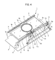
Fig. 4 is a perspective view of the in-vehicle display apparatus illustrated inFig. 1 ; -
Fig. 5 is a front view of decorative rings of the in-vehicle display apparatus that have been moved to separate positions; -
Fig. 6 is a bottom view of the decorative rings in the same state as inFig. 5 ; -
Fig. 7 is a perspective view of the decorative rings in the same state as inFig. 5 ; -
Fig. 8 is a front view of the decorative rings in a state of being stored in storage spaces; -
Fig. 9 is a bottom view of the decorative rings in the same state as inFig. 8 ; -
Fig. 10 is a perspective view of the decorative rings in the same state as inFig. 8 ; -
Figs. 11A to 11E illustrate relationships between the positions to which the decorative rings move and image information displayed on the display panel; -
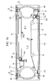
Fig. 12 is a front view of an in-vehicle display apparatus according to a further embodiment of the invention; -
Fig. 13 is a perspective view of the in-vehicle display apparatus illustrated inFig. 12 ; -
Fig. 14 is a perspective view of the in-vehicle display apparatus from which illustration of the display panel is omitted; -
Fig. 15 is a front view of a pair of frames of the in-vehicle display apparatus in a state of being stored in storage spaces; -
Fig. 16 is a bottom view of the pair of frames in the same state as inFig. 15 ; -
Fig. 17 is a perspective view of a main portion of the pair of frames in the same state as inFig. 15 ; and -
Figs. 18A to 18D illustrate the positions to which the pair of frames move relative to the display panel. - Referring now to the drawings, embodiments of the present invention will be described. Firstly, an embodiment of the present invention will be described referring to
Fig. 1 to Fig. 11E . As illustrated inFig. 1 , an in-vehicle display apparatus 1 is mounted on an instrument panel positioned in front of a driver's seat in a vehicle interior of a vehicle. The in-vehicle display apparatus 1 is covered by apanel cover 2 having arectangular opening 2a. The in-vehicle display apparatus 1 mainly includes abase board 3, which is attached to an installation portion of the vehicle, arectangular display panel 4, which is fixed to thebase board 3 and for which a component such as an LCD or an organic EL is employed, a pair ofdecorative rings driving mechanism 7, which drives thesedecorative rings display screen 4a of thedisplay panel 4 is visually perceived through theopening 2a of thepanel cover 2. Various types of information related to the conditions of the vehicle are displayed on thedisplay screen 4a, such as travel speed, engine speed, the remaining amount of fuel, the remaining battery life, the remaining amount of engine oil, and navigation information. - As illustrated in
Fig. 2 andFig. 4 , thebase board 3 has anerect support wall 3a, to which a pair ofguide members 8 are fixed. Theguide members 8 each have aguide groove 8a, which linearly extends along a long side of thedisplay panel 4. A pair ofguide rails 9 are fixed to thebase board 3. The pair ofguide members 8 and the pair ofguide rails 9 are disposed parallel to each other with thedisplay panel 4 interposed therebetween. The guide rails 9 each include ahorizontal portion 9a,arcuate portions 9b, andbent portions 9c. Thehorizontal portion 9a extends in the longitudinal direction (X1-X2 direction) of thedisplay screen 4a and thebent portions 9c extend from both ends of thehorizontal portion 9a via thearcuate portions 9b in a direction orthogonal tohorizontal portion 9a. The lower ends of thebent portions 9c are fixed to thebase board 3. - Three support stands 10 are mounted on the
base board 3 so as to be aligned along the guide rails 9. Afirst screw shaft 11 is rotatably supported by left and center support stands 10 and asecond screw shaft 12 is rotatably supported by center and right support stands 10. Agear 11a is securely fixed to a right end portion of thefirst screw shaft 11 and agear 12a is securely fixed to a left end portion of thesecond screw shaft 12. Thesegears display screen 4a. Anactuator 13 is fitted around thefirst screw shaft 11 and anengagement protrusion 13a of theactuator 13 is engaged in ahelical groove 11b of thefirst screw shaft 11. Similarly, anactuator 14 is fitted around thesecond screw shaft 12 and anengagement protrusion 14a of theactuator 14 is engaged in ahelical groove 12b of thesecond screw shaft 12. Amotor 15 is attached to theright support stand 10. Agear 15a, which is securely fixed to an output shaft of themotor 15, meshes with agear 12c, which is securely fixed to a right end portion of thesecond screw shaft 12. Thus, when themotor 15 rotates forward or backward, the first andsecond screw shafts actuators corresponding screw shafts detection switch 16 is mounted on thecenter support stand 10. Starting points of thedecorative rings detection switch 16. Thedetection switch 16 is positioned within a range in which theactuator 14 is movable. When theactuator 14 moves to a center portion of thedisplay screen 4a along thesecond screw shaft 12, thedetection switch 16 is turned on and outputs a switch signal. - The pair of
decorative rings display screen 4a. Thedecorative ring 5 on the left has a C shape and thedecorative ring 6 on the right has an inverted C shape. Thedecorative ring 5 hasswing pieces 5a and thedecorative ring 6 hasswing pieces 6a. Theseswing pieces display panel 4. One of theswing pieces 5a and one of theswing pieces 6a are slidably and rotatably inserted into theguide grooves 8a of thecorresponding guide members 8. Theother swing piece 5a and theother swing piece 6a are rotatably and pivotally supported by the correspondingactuators swing pieces guide protrusions swing piece actuator guide protrusion corresponding guide rail 9 by an urging force of the torsion coil spring. - Thus, when the first and
second screw shafts motor 15 and thus theactuators corresponding screw shafts guide protrusions swing pieces actuators guide protrusions guide rails 9 during sliding, the positions of thedecorative rings guide protrusions horizontal portions 9a of theguide rails 9, thedecorative rings opening 2a of thepanel cover 2 in the right-left direction while being in a parallel position in relation to thedisplay screen 4a. When theguide protrusions arcuate portions 9b of theguide rails 9 toward thebent portions 9c, thedecorative rings display screen 4a while being in inclined positions. The above-mentioneddriving mechanism 7 includes components such as themotor 15 and theactuators decorative rings decorative rings swing pieces display screen 4a. - Referring now to
Figs. 11A to 11E , an operation of the in-vehicle display apparatus 1 having the above-described configuration will be described. When the engine (or accessories) is off, the pair ofdecorative rings display screen 4a and are stored in the storage spaces S on both right and left sides of thedisplay panel 4, as illustrated inFig. 11A . Thus, the "dead front" design, in which the presence of thedisplay panel 4 is not perceived until the power is turned on, is realized. In this case, as illustrated inFig. 8 to Fig. 10 , thedecorative rings decorative rings guide protrusions bent portions 9c of the guide rails 9. Thus, the dimensions of the storage spaces S in the right-left direction (X1-X2 direction) can be reduced and, accordingly, the size of the whole in-vehicle display apparatus 1 in the longitudinal direction can be reduced. - From this state, when the engine (or accessories) is turned on and the in-
vehicle display apparatus 1 is turned on, first, themotor 15 starts rotating forward or backward and then the first andsecond screw shafts actuators screw shafts decorative rings display screen 4a, as illustrated inFig. 11B . In this case, as illustrated inFig. 5 to Fig. 7 , contact positions at which theguide protrusions guide rails 9 change from thebent portions 9c to thehorizontal portion 9a via thearcuate portions 9b as theactuators decorative rings display screen 4a while remaining in the horizontal positions. - When the
decorative rings display screen 4a in this manner, thedetection switch 16 is turned on by theright actuator 14 and thus themotor 15 temporarily stops in response to an output signal from thedetection switch 16. Consequently, thedecorative rings display screen 4a and thus results of system check such as the states of the engine oil or battery are displayed on areas of thedisplay screen 4a outside of thedecorative rings Fig. 11C . Here, as illustrated inFig. 2 to Fig. 4 , theguide protrusions horizontal portions 9a of the guide rails 9. Thus, the pair ofdecorative rings display screen 4a while being in the horizontal positions and form one annular member. - While the vehicle is running or stopped, if the direction in which and the speed at which the
motor 15 rotates are controlled with reference to the starting points detected by thedetection switch 16 so that the pair ofdecorative rings display screen 4a, vehicle related information can be stereoscopically and selectively displayed. For example, as illustrated inFig. 11D , while engine speed and travel speed are displayed on thedisplay screen 4a, if thedecorative rings display screen 4a displaying vehicle related information (such as engine speed or travel speed) can be highlighted by being separated from the surroundings. Alternatively, as illustrated inFig. 11E , when thedisplay screen 4a is switched to a navigation mode and thedecorative rings display screen 4a and stored in the storage spaces S, the entirety of thedisplay screen 4a can serve as a navigation screen, i.e., full screen display is achieved. - As described above, in the in-
vehicle display apparatus 1 according to the embodiment, by moving thedecorative rings display panel 4, vehicle related information can be stereoscopically and selectively displayed, for example, a specific type of vehicle related information displayed on thedisplay screen 4a of thedisplay panel 4 is surrounded by the annularly joineddecorative rings display screen 4a are individually and partially surrounded by the correspondingdecorative rings display panel 4 is off, thesedecorative rings display panel 4 in the longitudinal direction and stored in the storage spaces S. Thus, thedecorative rings display screen 4a that no longer displays images and becomes dark, thereby realizing a design called the "dead front" design, in which the presence of thedisplay panel 4 is not perceived. Furthermore, since thedecorative rings vehicle display apparatus 1 in the longitudinal direction can be prevented from increasing. - In the embodiment, the
driving mechanism 7, which drives thedecorative rings motor 15, the first andsecond screw shafts motor 15, and the pair ofactuators display screen 4a as thescrew shafts decorative rings actuators guide protrusions decorative rings decorative rings decorative rings second screw shafts display panel 4 so that thescrew shafts decorative rings single motor 15 to reciprocate toward and away from each other. Thus, the entirety of thedriving mechanism 7 can have a simple configuration, leading to space saving. - In this embodiment, the
guide rails 9 are used as guide mechanisms that regulate the angles at which thedecorative rings horizontal portion 9a, which extends parallel with thecorresponding screw shaft bent portions 9c, which extend from the ends of thehorizontal portion 9a via thearcuate portions 9b in the direction perpendicular to thehorizontal portion 9a. In addition, theguide protrusions decorative rings guide rails 9 by the urging force of torsion coil springs (spring members). Thus, the guide mechanism can be simply made with this configuration. Guide grooves having a shape similar to theguide rails 9 are also employable as guide mechanisms and theguide protrusions decorative rings - In the present embodiment, by joining the end portions of the first and
second screw shafts display panel 4, thescrew shafts single motor 15. However, the first andsecond screw shafts second screw shafts display panel 4 while facing each other, the pair ofdecorative rings display screen 4a. Here, thedecorative rings display screen 4a. - In the present embodiment, the pair of
decorative rings display screen 4a, serve as frames and thedecorative rings display screen 4a. However, a frame may be formed as an integrated annular member that is not divided into two parts. This frame may be caused to reciprocate in the longitudinal direction of thedisplay screen 4a while being in a horizontal position and may be rotated on a side of thedisplay panel 4 in the longitudinal direction of thedisplay panel 4 and stored in a storage space S. - In this case, a driving mechanism that actuates the frame includes a motor, a screw shaft, which is driven to rotate by the motor, and an actuator, which linearly moves in the longitudinal direction of the
display screen 4a as the screw shaft rotates. The frame may be rotatably and pivotally supported by the actuator and a guide mechanism that regulates the angle at which the frame rotates may be provided. The guide mechanism may be a guide rail that includes a horizontal portion, which extends parallel to the screw shaft, and a bent portion, which is continuous with one end of the horizontal portion. The frame may have a guide protrusion that slides over the guide rail. The guide protrusion may be pressed against the guide rail by the urging force of a spring member. - Referring now to
Fig. 12 to Fig. 18D , a further embodiment of the present invention will be described. An in-vehicle display apparatus 20 mainly includes abase board 21, which is attached to an installation portion of the vehicle, arectangular display panel 22, which is fixed to thebase board 21 and for which a component such as an LCD or an organic EL is employed, first and seconddecorative rings mechanisms 25, which drive thesedecorative rings display screen 22a of thedisplay panel 22 is visually perceived through an opening of a panel cover, which is not illustrated. - The
base board 21 has a pair oferect support walls support walls display panel 22 interposed therebetween. InFig. 14 , one of thesupport walls 21a is drawn by a chain double-dashed line.Guide shafts 26 are fixed to inner surfaces of thesupport walls guide shafts 26 linearly extend along the long sides of thedisplay panel 22. Each of thesupport walls guide grooves 27. Eachguide groove 27 has ahorizontal portion 27a, anarcuate portion 27b, and abent portion 27c. Thehorizontal portion 27a extends in the longitudinal direction (X1-X2 direction ofFig. 12 ) of thedisplay screen 22a and thebent portion 27c extends in a direction perpendicular to thehorizontal portion 27a from an end portion of thehorizontal portion 27a via thearcuate portion 27b. - Six
pulleys 28 are pivotally supported by thebase board 21. Afirst timing belt 29 is wound around four of the six pulleys disposed near thelower support wall 21a and asecond timing belt 30 is wound around remaining two of the six pulleys disposed near theupper support wall 21b. Afirst actuator 31 is securely fixed to thefirst timing belt 29. Thefirst actuator 31 is slidably fitted around one of theguide shafts 26. Similarly, asecond actuator 32 is securely fixed to thesecond timing belt 30. Thesecond actuator 32 is slidably fitted around theother guide shaft 26. First andsecond motors base board 21. Aworm 33a securely fixed to an output shaft of thefirst motor 33 meshes with aworm wheel 28a attached to anearby pulley 28. Aworm 34a securely fixed to an output shaft of thesecond motor 34 meshes with aworm wheel 28b attached to anearby pulley 28. Thus, when the first andsecond motors second actuators corresponding guide shafts 26. - Detection switches 35 and 36 are attached to the inner surfaces of the
support walls decorative rings detection switch 35 is positioned within a range in which thefirst actuator 31 is movable. When thefirst actuator 31 moves rightward (in the X2 direction) from the left edge of thedisplay screen 22a and becomes separated from thedetection switch 35, a contact of thedetection switch 35 is subjected to a switching operation so that thedetection switch 35 outputs a switch signal. Thedetection switch 36 is positioned within a range in which thesecond actuator 32 is movable. When thesecond actuator 32 moves leftward (in the X1 direction) from the right edge of thedisplay screen 22a and becomes separated from thedetection switch 36, a contact of thedetection switch 36 is subjected to a switching operation so that thedetection switch 36 outputs a switch signal. - The first
decorative ring 23 includes two semicircular components obtained by dividing an annular member into two parts along a line extending in the lateral direction (Y1-Y2 direction ofFig. 12 ) of thedisplay screen 22a, that is, a firstmovable frame 37, which is an inverted C shaped component disposed on the right side, and a firstrotatable frame 38, which is a C shaped component disposed on the left side. The firstmovable frame 37 includesprotrusion pieces 37a that protrude toward the long sides of thedisplay panel 22. One of theprotrusion pieces 37a is fixed to thefirst actuator 31 and theother protrusion piece 37a is slidably fitted around the correspondingguide shaft 26. The firstrotatable frame 38 hasswing pieces 38a, which are L shaped and protrude toward the long sides of thedisplay panel 22. Theseswing pieces 38a are rotatably and pivotally supported by theprotrusion pieces 37a of the firstmovable frame 37. Furthermore, eachswing piece 38a has anengagement pin 38b, which is slidably inserted into thecorresponding guide groove 27 formed in thesupport wall - Thus, when the
first timing belt 29 is driven by thefirst motor 33 to rotate around thepulleys 28 and thefirst actuator 31 linearly moves in the axis direction of the guide shafts 26 (in the X1-X2 direction ofFig. 12 ), the firstmovable frame 37 fixed to thefirst actuator 31 and the firstrotatable frame 38 pivotally supported by theprotrusion pieces 37a of the firstrotatable frame 37 move together in an integrated manner in front of thedisplay screen 22a. Then, the firstrotatable frame 38 changes its position in accordance with the positions of the engagement pins 38b with respect to theguide grooves 27 during sliding. Specifically, when the engagement pins 38b slide over thehorizontal portions 27a of theguide grooves 27, the firstmovable frame 37 and the firstrotatable frame 38 move in the right-left direction while being in a parallel position in relation to thedisplay screen 22a. When the engagement pins 38b slide over thearcuate portions 27b of theguide grooves 27 toward thebent portions 27c, only the firstrotatable frame 38 rotates downward approximately 45 degrees and is stored in a storage space S on a side of thedisplay screen 22a while being in an inclined position. - Similarly, the second
decorative ring 24 includes two semicircular components obtained by dividing an annular member into two parts along a line extending in the lateral direction of thedisplay screen 22a, that is, a secondmovable frame 39, which is a C shaped component disposed on the left side, and a secondrotatable frame 40, which is an inverted C shaped component disposed on the right side. The secondmovable frame 39 includesprotrusion pieces 39a that protrude toward the long sides of thedisplay panel 22. One of theprotrusion pieces 39a is slidably fitted around the correspondingguide shaft 26 and theother protrusion piece 39a is fixed to thesecond actuator 32. The secondrotatable frame 40 hasswing pieces 40a, which are L shaped and protrude toward the long sides of thedisplay panel 22. Theseswing pieces 40a are rotatably and pivotally supported by theprotrusion pieces 39a of the secondmovable frame 39. Furthermore, eachswing piece 40a has anengagement pin 40b, which is slidably inserted into thecorresponding guide groove 27 formed in thesupport wall - Thus, when the
second timing belt 30 is driven by thesecond motor 34 to rotate around thepulleys 28 and thesecond actuator 32 linearly moves in the axis direction of theguide shafts 26, the secondmovable frame 39 fixed to thesecond actuator 32 and the secondrotatable frame 40 pivotally supported by theprotrusion pieces 39a of the secondrotatable frame 39 move together in an integrated manner in front of thedisplay screen 22a. Then, the secondrotatable frame 40 changes its position in accordance with the positions of the engagement pins 40b with respect to theguide grooves 27 during sliding. Specifically, when the engagement pins 40b slide over thehorizontal portions 27a of theguide grooves 27, the secondmovable frame 39 and the secondrotatable frame 40 move in the right-left direction while being in a parallel position in relation to thedisplay screen 22a. When the engagement pins 40b slide over thearcuate portions 27b of theguide grooves 27 toward thebent portions 27c, only the secondrotatable frame 40 rotates downward approximately 45 degrees and is stored in a storage space S on a side of thedisplay screen 22a while being in an inclined position. - A
driving mechanism 25 that drives the firstdecorative ring 23 includes components such as thefirst motor 33, thefirst timing belt 29, thefirst actuator 31, and theswing pieces 38a. Adriving mechanism 25 that drives the seconddecorative ring 24 includes components such as thesecond motor 34, thesecond timing belt 30, thesecond actuator 32, and theswing pieces 40a. The in-vehicle display apparatus 20 according to the present embodiment includes the first and seconddecorative rings mechanisms 25. Approximately half of thedecorative rings movable frames 37 and 39) that move while being in parallel positions in relation to thedisplay screen 22a and approximately the other half of thedecorative rings display screen 22a. - Referring now to
Figs. 18A to 18D , an operation of the in-vehicle display apparatus 20 according to the present embodiment will be described. When the engine (or accessories) is off, the first and seconddecorative rings display screen 22a and are stored in the storage spaces S on both right and left sides of thedisplay panel 22, as illustrated inFig. 18A . Thus, the "dead front" design, in which the presence of thedisplay panel 22 is not perceived until the power is turned on, is realized. In this case, as illustrated inFig. 15 to Fig. 17 , the first and secondmovable frames decorative rings decorative rings display screen 22a, whereas the first and second rotatable frames 38 and 40 are stored in the storage spaces S while being in the inclined positions, in which the outer sides of the rotatable frames 38 and 40 are inclined downward, as a result of the engagement pins 38b and 40b being engaged with the lower end portions of thebent portions 27c of thecorresponding guide grooves 27. Thus, the dimensions of the storage spaces S in the right-left direction (X1-X2 direction) can be reduced further than in the case where the entireties of the first and seconddecorative rings vehicle display apparatus 1 in the longitudinal direction can be reduced. - From this state, when the engine (or accessories) is turned on and the in-
vehicle display apparatus 20 is turned on, first, thefirst motor 33 and/or thesecond motor 34 start rotating forward or backward and then thefirst actuator 31 and/or thesecond actuator 32 start moving linearly in the axis direction of thecorresponding guide shaft 26. For example, if thefirst motor 33 starts rotating while thesecond motor 34 is in a stationary state, thefirst actuator 31 starts moving from the outer side toward the inner side (in the X2 direction) along the axis of thecorresponding guide shaft 26. Consequently, the firstdecorative ring 23 that has been stored in the left storage space S appears in front of thedisplay screen 22a, as illustrated inFig. 18B . In this case, the positions at which the engagement pins 38b become engaged with theguide grooves 27 change from thebent portions 27c to thehorizontal portions 27a via thearcuate portions 27b as thefirst actuator 31 moves. Thus, the firstrotatable frame 38 changes its position from the inclined position to the horizontal position by rotating approximately 45 degrees and moves together with the firstmovable frame 37 in front of thedisplay screen 22a while keeping in the horizontal position. - On the other hand, if the
second motor 34 starts rotating while thefirst motor 33 is in a stationary state, thesecond actuator 33 starts moving from the outer side toward the inner side (in the X1 direction) in the axis direction of thecorresponding guide shaft 26. Consequently, the seconddecorative ring 24 that has been stored in the right storage space S appears in front of thedisplay screen 22a. In this case, the positions at which the engagement pins 40b become engaged with theguide grooves 27 change from thebent portions 27c to thehorizontal portions 27a via thearcuate portions 27b as thesecond actuator 32 moves. Thus, the secondrotatable frame 40 changes its position from the inclined position to the horizontal position by rotating approximately 45 degrees and moves together with the secondmovable frame 39 in front of thedisplay screen 22a while keeping in the horizontal position. Alternatively, if both first andsecond motors decorative rings display screen 22a, as illustrated inFig. 18C . - When the first and
second actuators display screen 22a and become separated from the detection switches 35 and 36, on/off switch signals are output from the detection switches 35 and 36 and the starting points of the first and seconddecorative rings second motors decorative rings display screen 22a, vehicle related information can be stereoscopically and selectively displayed. For example, as illustrated inFig. 18B , the firstdecorative ring 23 can be stopped at the center portion of thedisplay screen 22a so that results of system check, such as the states of the engine oil or battery, are displayed on thedisplay screen 22a in an area surrounded by the firstdecorative ring 23 as an initial screen. Alternatively, as illustrated inFig. 18C , the first and seconddecorative rings display screen 22a such that the vehicle related information, such as engine speed or travel speed, may be individually displayed on thedisplay screen 22a in areas surrounded by the first and seconddecorative rings Fig. 18D , the first and seconddecorative rings display screen 22a so that a different type of vehicle related information is displayed in an area of thedisplay screen 22a interposed between the firstdecorative ring 23 and the seconddecorative ring 24. Still alternatively, when thedisplay screen 22a is switched to a navigation mode, by moving the first and seconddecorative rings display screen 22a and storing thedecorative rings display screen 22a can be used as, for example, a navigation screen, i.e., full screen display is achieved. - As described above, the in-
vehicle display apparatus 20 according to the embodiment can stereoscopically and selectively display vehicle related information by moving the firstdecorative ring 23 and the seconddecorative ring 24 in the right-left direction in front of thedisplay panel 22, specifically, a specific type of vehicle related information displayed on thedisplay screen 22a of thedisplay panel 22 is annularly surrounded by thedecorative ring display screen 22a are individually surrounded by bothdecorative rings display panel 22 is off, the first and seconddecorative rings display panel 22 in the longitudinal direction. Thus, thedecorative rings display screen 22a that no longer displays images and becomes dark, thereby realizing a design called the "dead front" design, in which the presence of thedisplay panel 22 is not perceived. Furthermore, the firstdecorative ring 23 includes the semicircular firstmovable frame 37 and the semicircular firstrotatable frame 38, which are joined together such that the firstrotatable frame 38 is rotatable with respect to the firstmovable frame 37, and the seconddecorative ring 24 includes the semicircular secondmovable frame 39 and the semicircular secondrotatable frame 40, which are joined together such that the secondrotatable frame 40 is rotatable with respect to the secondmovable frame 39. Since the firstrotatable frame 38 and the secondrotatable frame 40 are stored in the storage spaces S while being in the inclined positions, the dimensions of the entire in-vehicle display apparatus 20 in the longitudinal direction and the thickness direction can be prevented from increasing. - In the embodiment, the
driving mechanism 25 for driving the firstdecorative ring 23 includes thefirst motor 33, thefirst timing belt 29, which is driven to rotate by thefirst motor 33, and thefirst actuator 31, which is joined to thefirst timing belt 29 and moves in the axis direction of theguide shafts 26. The firstmovable frame 37 is securely fixed to thefirst actuator 31, the firstrotatable frame 38 is rotatably joined to thefirst actuator 31, and the engagement pins 38b of the firstrotatable frame 38 are inserted into the guide grooves 27 (guide mechanisms) so that the angle at which the firstrotatable frame 38 rotates is regulated. Thus, the firstmovable frame 37 and the firstrotatable frame 38 can operate smoothly. Similarly, thedriving mechanism 25 for driving the seconddecorative ring 24 includes thesecond motor 34, thesecond timing belt 30, which is driven to rotate by thesecond motor 34, and thesecond actuator 32, which is joined to thesecond timing belt 30 and moves in the axis direction of theguide shafts 26. The secondmovable frame 39 is securely fixed to thesecond actuator 32, the secondrotatable frame 40 is rotatably joined to thesecond actuator 32, and the engagement pins 40b of the secondrotatable frame 40 are inserted into the guide grooves 27 (guide mechanisms) so that the angle at which the secondrotatable frame 40 rotates is regulated. Thus, the secondmovable frame 39 and the secondrotatable frame 40 can operate smoothly. - In this embodiment, the
guide grooves 27 are used as guide mechanisms that regulate the angles at which the first and second rotatable frames 38 and 40 rotate. Eachguide groove 27 has thehorizontal portion 27a, which extends parallel to thecorresponding guide shaft 26, and thebent portion 27c, which extends in the direction perpendicular to thehorizontal portion 27a from one end of thehorizontal portion 27a via thearcuate portion 27b. The engagement pins 38b and 40b of theswing pieces guide grooves 27. Thus, the guide mechanism can be simply made with this configuration. - In the present embodiment, the case where two frames, i.e., the first
decorative ring 23 and the seconddecorative ring 24, are used is described. However, either the firstdecorative ring 23 or the seconddecorative ring 24 may be omitted and only one frame may be moved in the right-left direction in front of thedisplay panel 22.
Claims (12)
- An in-vehicle display apparatus (1, 20) comprising:a display panel (4, 22) including a rectangular display screen (4a, 22a);a frame positioned in front of the display panel (4, 22), the frame surrounding at least part of an outer periphery of an image displayed on the display panel (4, 22); anda driving mechanism that drives the frame to reciprocate in a longitudinal direction of the display screen (4a, 22a),wherein at least part of the frame forms a rotatable frame that is rotatable around an axis extending in a lateral direction of the display screen (4a, 22a),wherein the driving mechanism moves the frame while the frame is in front of the display panel (4, 22) and in a parallel position in relation to the display screen (4a, 22a), andwherein the rotatable frame is rotated on a side of the display panel (4, 22) in a longitudinal direction of the display panel (4, 22) and stored in a storage space (S).
- The in-vehicle display apparatus (1) according to Claim 1,
wherein the driving mechanism includes a motor (15), a screw shaft (11, 12) that is driven to rotate by the motor (15), and an actuator (13, 14) that linearly moves in the longitudinal direction of the display screen (4a) as the screw shaft (11, 12) rotates, and
wherein the actuator (13, 14) includes a guide mechanism that rotatably and pivotally supports the rotatable frame and that regulates an angle at which the rotatable frame rotates. - The in-vehicle display apparatus (1) according to Claim 2,
wherein the guide mechanism includes a guide rail (9) including a horizontal portion (9a) that extends parallel to the screw shaft (11, 12) and a bent portion (9c) that is continuous with an end of the horizontal portion (9a), and
wherein the rotatable frame includes a guide protrusion (5b, 6b) that slides over the guide rail (9) and the guide protrusion (5b, 6b) is pressed against the guide rail (9) by an urging force of a spring member. - The in-vehicle display apparatus (20) according to any one of Claims 1-3,
wherein the driving mechanism includes a motor (33, 34), a timing belt (29, 30) driven by the motor (33, 34) to rotate between a pair of pulleys (28), and an actuator (31, 32) joined to the timing belt (29, 30), the actuator (31, 32) moving along a guide shaft (26) that extends in a longitudinal direction of the display screen (22a),
wherein the actuator (31, 32) rotatably and pivotally supports the rotatable frame (38, 40), and
wherein a guide mechanism is provided to regulate an angle at which the rotatable frame (38, 40) rotates. - The in-vehicle display apparatus (20) according to Claim 4,
wherein the guide mechanism includes a guide groove (27) including a horizontal portion (27a) that extends parallel to the guide shaft (26) and a bent portion (27c) that is continuous with an end of the horizontal portion (27a), and
wherein the rotatable frame includes a guide protrusion (38b, 40b) that fits into the guide groove (27). - The in-vehicle display apparatus (1) according to any one of Claims 1-5,
wherein the frame includes a pair of semicircular decorative rings (5, 6) obtained by dividing an annular member into two parts along a line extending in the lateral direction of the display screen (4a), the decorative rings (5, 6) being individually rotatable around axes extending in the lateral direction of the display screen (4a),
wherein the driving mechanism drives the pair of decorative rings (5, 6) to reciprocate toward and away from each other in the longitudinal direction of the display screen (4a), and
wherein the driving mechanism drives the decorative rings (5, 6) to rotate on both sides of the display panel (4) in the longitudinal direction and stores the decorative rings (5, 6) in storage spaces (S). - The in-vehicle display apparatus (1) according to Claim 6,
wherein the driving mechanism includes a motor (15), a pair of screw shafts (11, 12) driven to rotate by the motor (15), and a pair of actuators (13, 14) that linearly move in the longitudinal direction of the display screen (4a) as the screw shafts (11, 12) rotate,
wherein the decorative rings (5, 6) are rotatably and pivotally supported by the actuators (13, 14), and
wherein a guide mechanism is provided to regulate angles at which the decorative rings (5, 6) rotate. - The in-vehicle display apparatus (1) according to Claim 7, wherein the pair of screw shafts (11, 12) are jointed together via a gear (11a, 12a) in a center portion of the display panel (4) in the longitudinal direction of the display panel (4) so as to rotate in opposite directions.
- The in-vehicle display apparatus (1) according to Claim 7 or 8,
wherein the guide mechanism includes a guide rail (9) including a horizontal portion (9a) that extends parallel to the screw shafts (11, 12) and a bent portion (9c) that is continuous with an end of the horizontal portion (9a), and
wherein each of the decorative rings (5, 6) includes a guide protrusion (5b, 6b) that slides over the guide rail (9) and the guide protrusion (5b, 6b) is pressed against the guide rail (9) by an urging force of a spring member. - The in-vehicle display apparatus (20) according to any one of Claims 1-9,
wherein the frame includes a pair of semicircular members (37, 38, 39, 40) obtained by dividing an annular member into two parts along a line extending in the lateral direction of the display screen (22a), one of the semicircular members is a movable frame (37, 39) that moves while being in a parallel position in relation to the display screen (4a, 22a), and the other semicircular member is the rotatable frame (38, 40) rotatably and pivotally supported by the movable frame (37, 39),
wherein the driving mechanism drives the movable frame (37, 39) and the rotatable frame (38, 40) to reciprocate in the longitudinal direction of the display screen (22a) while the movable frame (37, 39) and the rotatable frame (38, 40) are annularly joined, and
wherein the rotatable frame (38, 40) is rotated on a side of the display panel (22) in the longitudinal direction of the display panel (22) and stored in the storage space (S). - The in-vehicle display apparatus (20) according to Claim 10,
wherein the driving mechanism includes a motor (33, 34), a timing belt (29, 30) driven by the motor (33, 34) to rotate, and an actuator (31, 32) joined to the timing belt (29, 30), the actuator (31, 32) moving along a guide shaft (26) that extends in a longitudinal direction of the display screen (22a),
wherein the movable frame (37, 39) is securely fixed to the actuator (31, 32) and the rotatable frame (38, 40) is rotatably joined to the actuator (31, 32), and
wherein a guide mechanism is provided to regulate an angle at which the rotatable frame (38, 40) rotates. - The in-vehicle display apparatus (20) according to Claim 11,
wherein the guide mechanism includes a guide groove (27) including a horizontal portion (27a) that extends parallel to the guide shaft (26) and a bent portion (27c) that is continuous with an end of the horizontal portion (27a), and
wherein the rotatable frame (38, 40) includes an engagement protrusion (38b, 40b) that fits into the guide groove (27).
Applications Claiming Priority (2)
| Application Number | Priority Date | Filing Date | Title |
|---|---|---|---|
| JP2012194251 | 2012-09-04 | ||
| JP2013104218A JP6080681B2 (en) | 2012-09-04 | 2013-05-16 | In-vehicle display device |
Publications (2)
| Publication Number | Publication Date |
|---|---|
| EP2703206A1 true EP2703206A1 (en) | 2014-03-05 |
| EP2703206B1 EP2703206B1 (en) | 2016-01-13 |
Family
ID=49083561
Family Applications (1)
| Application Number | Title | Priority Date | Filing Date |
|---|---|---|---|
| EP13182438.5A Not-in-force EP2703206B1 (en) | 2012-09-04 | 2013-08-30 | In-vehicle display apparatus |
Country Status (3)
| Country | Link |
|---|---|
| US (1) | US9036336B2 (en) |
| EP (1) | EP2703206B1 (en) |
| JP (1) | JP6080681B2 (en) |
Cited By (5)
| Publication number | Priority date | Publication date | Assignee | Title |
|---|---|---|---|---|
| US20140216329A1 (en) * | 2011-08-23 | 2014-08-07 | Nippon Seiki Co.,Ltd. | Display device |
| CN106274489A (en) * | 2016-08-28 | 2017-01-04 | 赵夫超 | A kind of automobile middle control screen light-proof housing |
| CN106687772A (en) * | 2014-09-05 | 2017-05-17 | 株式会社电装 | Display device |
| CN109263474A (en) * | 2014-07-18 | 2019-01-25 | 株式会社电装 | Display device |
| CN115991096A (en) * | 2023-03-24 | 2023-04-21 | 成都工业职业技术学院 | A control device for a hybrid vehicle |
Families Citing this family (10)
| Publication number | Priority date | Publication date | Assignee | Title |
|---|---|---|---|---|
| JP5971700B2 (en) * | 2012-05-17 | 2016-08-17 | アルパイン株式会社 | Display device |
| CN103716428B (en) * | 2013-12-30 | 2016-03-02 | 京东方科技集团股份有限公司 | Portable display apparatus |
| WO2015191866A1 (en) | 2014-06-13 | 2015-12-17 | Kis-Benedek Pinero Iidiko' | Portable display device and system |
| WO2016035304A1 (en) * | 2014-09-05 | 2016-03-10 | 株式会社デンソー | Display device |
| JP6162099B2 (en) * | 2014-12-17 | 2017-07-12 | 矢崎総業株式会社 | Vehicle display device |
| KR102266192B1 (en) * | 2015-02-02 | 2021-06-17 | 삼성디스플레이 주식회사 | Display device |
| JP6760903B2 (en) * | 2017-09-01 | 2020-09-23 | 矢崎総業株式会社 | Vehicle display device |
| US10787077B2 (en) * | 2018-11-20 | 2020-09-29 | Denso International America, Inc. | Floating ring pointer assembly |
| CN119489753B (en) * | 2023-08-16 | 2026-04-21 | 长城汽车股份有限公司 | The installation structure of the display screen and the vehicle |
| FR3171805A1 (en) * | 2025-02-03 | 2026-08-07 | Stellantis Auto Sas | Configurable instrumentation and associated kinematics combination. |
Citations (4)
| Publication number | Priority date | Publication date | Assignee | Title |
|---|---|---|---|---|
| DE4240465A1 (en) * | 1992-12-02 | 1994-06-09 | Vdo Schindling | Combination instrument for vehicle dashboard - has primary tachometer display displaced from original position for viewing partially overlapped secondary liquid crystal display |
| DE102004024596A1 (en) * | 2003-09-09 | 2005-03-31 | Volkswagen Ag | Display arrangement e.g. for motor vehicle, has display element movably mounted between usage position in front of display second position |
| US20060092001A1 (en) * | 2004-11-02 | 2006-05-04 | Yazaki Corporation | Display unit |
| US20080024288A1 (en) * | 2006-07-28 | 2008-01-31 | Yazaki Corporation | Vehicle display device |
Family Cites Families (14)
| Publication number | Priority date | Publication date | Assignee | Title |
|---|---|---|---|---|
| US5768096A (en) * | 1996-10-30 | 1998-06-16 | Hewlett-Packard Company | Portable computer with movable display panels forming a concatenated display screen in response to opening the computer |
| JP2001030848A (en) * | 1999-07-15 | 2001-02-06 | Xanavi Informatics Corp | In-vehicle display drive mechanism and display device |
| US6844865B2 (en) * | 1999-08-09 | 2005-01-18 | Michael Stasko | Multiple screen computer monitor |
| US6859219B1 (en) * | 1999-10-08 | 2005-02-22 | Gateway, Inc. | Method and apparatus having multiple display devices |
| JP2005017968A (en) * | 2003-06-30 | 2005-01-20 | Fujitsu Ten Ltd | Electronics |
| US7237202B2 (en) * | 2004-05-11 | 2007-06-26 | Cynthia Joanne Gage | Multiple document viewing apparatus and user interface |
| TWI291626B (en) * | 2005-12-23 | 2007-12-21 | Asustek Comp Inc | Portable electronic device capable of inserting display monitor into housing |
| KR100703514B1 (en) * | 2006-04-07 | 2007-04-03 | 삼성에스디아이 주식회사 | Dual screen mobile display devices |
| US20070247798A1 (en) * | 2006-04-20 | 2007-10-25 | International Business Machines Corporation | Display having a variable display size for use in portable electronic devices and methods for controlling same |
| JP5246598B2 (en) * | 2009-05-29 | 2013-07-24 | 日本精機株式会社 | Display device |
| JP5720494B2 (en) * | 2011-08-23 | 2015-05-20 | 日本精機株式会社 | Display device |
| JP5959208B2 (en) * | 2012-01-20 | 2016-08-02 | アルパイン株式会社 | Vehicle display device |
| JP5971700B2 (en) * | 2012-05-17 | 2016-08-17 | アルパイン株式会社 | Display device |
| JP6177565B2 (en) * | 2013-04-02 | 2017-08-09 | アルパイン株式会社 | In-vehicle display system |
-
2013
- 2013-05-16 JP JP2013104218A patent/JP6080681B2/en not_active Expired - Fee Related
- 2013-07-26 US US13/951,877 patent/US9036336B2/en not_active Expired - Fee Related
- 2013-08-30 EP EP13182438.5A patent/EP2703206B1/en not_active Not-in-force
Patent Citations (5)
| Publication number | Priority date | Publication date | Assignee | Title |
|---|---|---|---|---|
| DE4240465A1 (en) * | 1992-12-02 | 1994-06-09 | Vdo Schindling | Combination instrument for vehicle dashboard - has primary tachometer display displaced from original position for viewing partially overlapped secondary liquid crystal display |
| DE102004024596A1 (en) * | 2003-09-09 | 2005-03-31 | Volkswagen Ag | Display arrangement e.g. for motor vehicle, has display element movably mounted between usage position in front of display second position |
| US20060092001A1 (en) * | 2004-11-02 | 2006-05-04 | Yazaki Corporation | Display unit |
| US7382234B2 (en) | 2004-11-02 | 2008-06-03 | Yazaki Corporation | Display unit |
| US20080024288A1 (en) * | 2006-07-28 | 2008-01-31 | Yazaki Corporation | Vehicle display device |
Cited By (8)
| Publication number | Priority date | Publication date | Assignee | Title |
|---|---|---|---|---|
| US20140216329A1 (en) * | 2011-08-23 | 2014-08-07 | Nippon Seiki Co.,Ltd. | Display device |
| US9272623B2 (en) * | 2011-08-23 | 2016-03-01 | Nippon Seiki Co., Ltd. | Display device |
| CN109263474A (en) * | 2014-07-18 | 2019-01-25 | 株式会社电装 | Display device |
| CN106687772A (en) * | 2014-09-05 | 2017-05-17 | 株式会社电装 | Display device |
| CN106687772B (en) * | 2014-09-05 | 2020-04-21 | 株式会社电装 | display device |
| CN106274489A (en) * | 2016-08-28 | 2017-01-04 | 赵夫超 | A kind of automobile middle control screen light-proof housing |
| CN115991096A (en) * | 2023-03-24 | 2023-04-21 | 成都工业职业技术学院 | A control device for a hybrid vehicle |
| CN115991096B (en) * | 2023-03-24 | 2023-05-16 | 成都工业职业技术学院 | Control device for hybrid vehicle |
Also Published As
| Publication number | Publication date |
|---|---|
| US20140063718A1 (en) | 2014-03-06 |
| US9036336B2 (en) | 2015-05-19 |
| EP2703206B1 (en) | 2016-01-13 |
| JP2014066696A (en) | 2014-04-17 |
| JP6080681B2 (en) | 2017-02-15 |
Similar Documents
| Publication | Publication Date | Title |
|---|---|---|
| EP2703206B1 (en) | In-vehicle display apparatus | |
| MX2014000009A (en) | FRONT DISPLAY SCREEN FOR A VEHICLE. | |
| JP6124685B2 (en) | Display device | |
| JP6116257B2 (en) | Head-up display device | |
| CN106536255B (en) | Display device | |
| JP5236251B2 (en) | Display device | |
| JP6498138B2 (en) | Monitor rotation mechanism and monitor equipped with the monitor rotation mechanism | |
| EP3312040A1 (en) | Head-up display device | |
| EP2712767B1 (en) | On-vehicle electronic device | |
| JP2015182635A (en) | Head-up display device | |
| JP6760903B2 (en) | Vehicle display device | |
| CN107089141A (en) | Automobile-used display system | |
| JP6093313B2 (en) | Head-up display device | |
| US10288880B2 (en) | Panel opening/closing device | |
| EP3299206A1 (en) | Display apparatus | |
| JP2014115223A (en) | On-vehicle display device | |
| JPWO2016147372A1 (en) | Display device | |
| US10464477B2 (en) | Vehicle display device | |
| JP2019190925A (en) | Vehicle display system | |
| JP2016179743A (en) | Opening and closing mechanism for display device | |
| JP2008143227A (en) | Inner mirror | |
| WO2016051507A1 (en) | Display device | |
| JP2005119471A (en) | Vehicular display device | |
| WO2017183306A1 (en) | Display device |
Legal Events
| Date | Code | Title | Description |
|---|---|---|---|
| AK | Designated contracting states |
Kind code of ref document: A1 Designated state(s): AL AT BE BG CH CY CZ DE DK EE ES FI FR GB GR HR HU IE IS IT LI LT LU LV MC MK MT NL NO PL PT RO RS SE SI SK SM TR |
|
| AX | Request for extension of the european patent |
Extension state: BA ME |
|
| PUAI | Public reference made under article 153(3) epc to a published international application that has entered the european phase |
Free format text: ORIGINAL CODE: 0009012 |
|
| 17P | Request for examination filed |
Effective date: 20140618 |
|
| RBV | Designated contracting states (corrected) |
Designated state(s): AL AT BE BG CH CY CZ DE DK EE ES FI FR GB GR HR HU IE IS IT LI LT LU LV MC MK MT NL NO PL PT RO RS SE SI SK SM TR |
|
| RIC1 | Information provided on ipc code assigned before grant |
Ipc: B60K 37/02 20060101ALI20150619BHEP Ipc: H05K 5/00 20060101ALI20150619BHEP Ipc: B60K 35/00 20060101AFI20150619BHEP Ipc: G01D 7/00 20060101ALI20150619BHEP Ipc: G01D 11/30 20060101ALI20150619BHEP |
|
| GRAP | Despatch of communication of intention to grant a patent |
Free format text: ORIGINAL CODE: EPIDOSNIGR1 |
|
| INTG | Intention to grant announced |
Effective date: 20150826 |
|
| GRAS | Grant fee paid |
Free format text: ORIGINAL CODE: EPIDOSNIGR3 |
|
| GRAA | (expected) grant |
Free format text: ORIGINAL CODE: 0009210 |
|
| AK | Designated contracting states |
Kind code of ref document: B1 Designated state(s): AL AT BE BG CH CY CZ DE DK EE ES FI FR GB GR HR HU IE IS IT LI LT LU LV MC MK MT NL NO PL PT RO RS SE SI SK SM TR |
|
| REG | Reference to a national code |
Ref country code: GB Ref legal event code: FG4D |
|
| REG | Reference to a national code |
Ref country code: CH Ref legal event code: EP |
|
| REG | Reference to a national code |
Ref country code: IE Ref legal event code: FG4D |
|
| REG | Reference to a national code |
Ref country code: AT Ref legal event code: REF Ref document number: 770267 Country of ref document: AT Kind code of ref document: T Effective date: 20160215 |
|
| REG | Reference to a national code |
Ref country code: DE Ref legal event code: R096 Ref document number: 602013004593 Country of ref document: DE |
|
| REG | Reference to a national code |
Ref country code: LT Ref legal event code: MG4D |
|
| REG | Reference to a national code |
Ref country code: NL Ref legal event code: MP Effective date: 20160113 |
|
| REG | Reference to a national code |
Ref country code: AT Ref legal event code: MK05 Ref document number: 770267 Country of ref document: AT Kind code of ref document: T Effective date: 20160113 |
|
| PG25 | Lapsed in a contracting state [announced via postgrant information from national office to epo] |
Ref country code: NL Free format text: LAPSE BECAUSE OF FAILURE TO SUBMIT A TRANSLATION OF THE DESCRIPTION OR TO PAY THE FEE WITHIN THE PRESCRIBED TIME-LIMIT Effective date: 20160113 |
|
| PG25 | Lapsed in a contracting state [announced via postgrant information from national office to epo] |
Ref country code: NO Free format text: LAPSE BECAUSE OF FAILURE TO SUBMIT A TRANSLATION OF THE DESCRIPTION OR TO PAY THE FEE WITHIN THE PRESCRIBED TIME-LIMIT Effective date: 20160413 Ref country code: HR Free format text: LAPSE BECAUSE OF FAILURE TO SUBMIT A TRANSLATION OF THE DESCRIPTION OR TO PAY THE FEE WITHIN THE PRESCRIBED TIME-LIMIT Effective date: 20160113 Ref country code: FI Free format text: LAPSE BECAUSE OF FAILURE TO SUBMIT A TRANSLATION OF THE DESCRIPTION OR TO PAY THE FEE WITHIN THE PRESCRIBED TIME-LIMIT Effective date: 20160113 Ref country code: IT Free format text: LAPSE BECAUSE OF FAILURE TO SUBMIT A TRANSLATION OF THE DESCRIPTION OR TO PAY THE FEE WITHIN THE PRESCRIBED TIME-LIMIT Effective date: 20160113 Ref country code: ES Free format text: LAPSE BECAUSE OF FAILURE TO SUBMIT A TRANSLATION OF THE DESCRIPTION OR TO PAY THE FEE WITHIN THE PRESCRIBED TIME-LIMIT Effective date: 20160113 Ref country code: GR Free format text: LAPSE BECAUSE OF FAILURE TO SUBMIT A TRANSLATION OF THE DESCRIPTION OR TO PAY THE FEE WITHIN THE PRESCRIBED TIME-LIMIT Effective date: 20160414 |
|
| REG | Reference to a national code |
Ref country code: FR Ref legal event code: PLFP Year of fee payment: 4 |
|
| PG25 | Lapsed in a contracting state [announced via postgrant information from national office to epo] |
Ref country code: RS Free format text: LAPSE BECAUSE OF FAILURE TO SUBMIT A TRANSLATION OF THE DESCRIPTION OR TO PAY THE FEE WITHIN THE PRESCRIBED TIME-LIMIT Effective date: 20160113 Ref country code: IS Free format text: LAPSE BECAUSE OF FAILURE TO SUBMIT A TRANSLATION OF THE DESCRIPTION OR TO PAY THE FEE WITHIN THE PRESCRIBED TIME-LIMIT Effective date: 20160513 Ref country code: SE Free format text: LAPSE BECAUSE OF FAILURE TO SUBMIT A TRANSLATION OF THE DESCRIPTION OR TO PAY THE FEE WITHIN THE PRESCRIBED TIME-LIMIT Effective date: 20160113 Ref country code: AT Free format text: LAPSE BECAUSE OF FAILURE TO SUBMIT A TRANSLATION OF THE DESCRIPTION OR TO PAY THE FEE WITHIN THE PRESCRIBED TIME-LIMIT Effective date: 20160113 Ref country code: LV Free format text: LAPSE BECAUSE OF FAILURE TO SUBMIT A TRANSLATION OF THE DESCRIPTION OR TO PAY THE FEE WITHIN THE PRESCRIBED TIME-LIMIT Effective date: 20160113 Ref country code: LT Free format text: LAPSE BECAUSE OF FAILURE TO SUBMIT A TRANSLATION OF THE DESCRIPTION OR TO PAY THE FEE WITHIN THE PRESCRIBED TIME-LIMIT Effective date: 20160113 Ref country code: PL Free format text: LAPSE BECAUSE OF FAILURE TO SUBMIT A TRANSLATION OF THE DESCRIPTION OR TO PAY THE FEE WITHIN THE PRESCRIBED TIME-LIMIT Effective date: 20160113 Ref country code: PT Free format text: LAPSE BECAUSE OF FAILURE TO SUBMIT A TRANSLATION OF THE DESCRIPTION OR TO PAY THE FEE WITHIN THE PRESCRIBED TIME-LIMIT Effective date: 20160513 |
|
| REG | Reference to a national code |
Ref country code: DE Ref legal event code: R097 Ref document number: 602013004593 Country of ref document: DE |
|
| PG25 | Lapsed in a contracting state [announced via postgrant information from national office to epo] |
Ref country code: DK Free format text: LAPSE BECAUSE OF FAILURE TO SUBMIT A TRANSLATION OF THE DESCRIPTION OR TO PAY THE FEE WITHIN THE PRESCRIBED TIME-LIMIT Effective date: 20160113 Ref country code: EE Free format text: LAPSE BECAUSE OF FAILURE TO SUBMIT A TRANSLATION OF THE DESCRIPTION OR TO PAY THE FEE WITHIN THE PRESCRIBED TIME-LIMIT Effective date: 20160113 |
|
| PLBE | No opposition filed within time limit |
Free format text: ORIGINAL CODE: 0009261 |
|
| STAA | Information on the status of an ep patent application or granted ep patent |
Free format text: STATUS: NO OPPOSITION FILED WITHIN TIME LIMIT |
|
| PG25 | Lapsed in a contracting state [announced via postgrant information from national office to epo] |
Ref country code: CZ Free format text: LAPSE BECAUSE OF FAILURE TO SUBMIT A TRANSLATION OF THE DESCRIPTION OR TO PAY THE FEE WITHIN THE PRESCRIBED TIME-LIMIT Effective date: 20160113 Ref country code: RO Free format text: LAPSE BECAUSE OF FAILURE TO SUBMIT A TRANSLATION OF THE DESCRIPTION OR TO PAY THE FEE WITHIN THE PRESCRIBED TIME-LIMIT Effective date: 20160113 Ref country code: SK Free format text: LAPSE BECAUSE OF FAILURE TO SUBMIT A TRANSLATION OF THE DESCRIPTION OR TO PAY THE FEE WITHIN THE PRESCRIBED TIME-LIMIT Effective date: 20160113 Ref country code: SM Free format text: LAPSE BECAUSE OF FAILURE TO SUBMIT A TRANSLATION OF THE DESCRIPTION OR TO PAY THE FEE WITHIN THE PRESCRIBED TIME-LIMIT Effective date: 20160113 |
|
| 26N | No opposition filed |
Effective date: 20161014 |
|
| PG25 | Lapsed in a contracting state [announced via postgrant information from national office to epo] |
Ref country code: BE Free format text: LAPSE BECAUSE OF FAILURE TO SUBMIT A TRANSLATION OF THE DESCRIPTION OR TO PAY THE FEE WITHIN THE PRESCRIBED TIME-LIMIT Effective date: 20160113 |
|
| PG25 | Lapsed in a contracting state [announced via postgrant information from national office to epo] |
Ref country code: BG Free format text: LAPSE BECAUSE OF FAILURE TO SUBMIT A TRANSLATION OF THE DESCRIPTION OR TO PAY THE FEE WITHIN THE PRESCRIBED TIME-LIMIT Effective date: 20160413 Ref country code: SI Free format text: LAPSE BECAUSE OF FAILURE TO SUBMIT A TRANSLATION OF THE DESCRIPTION OR TO PAY THE FEE WITHIN THE PRESCRIBED TIME-LIMIT Effective date: 20160113 |
|
| PG25 | Lapsed in a contracting state [announced via postgrant information from national office to epo] |
Ref country code: MC Free format text: LAPSE BECAUSE OF FAILURE TO SUBMIT A TRANSLATION OF THE DESCRIPTION OR TO PAY THE FEE WITHIN THE PRESCRIBED TIME-LIMIT Effective date: 20160113 |
|
| REG | Reference to a national code |
Ref country code: CH Ref legal event code: PL |
|
| PG25 | Lapsed in a contracting state [announced via postgrant information from national office to epo] |
Ref country code: CH Free format text: LAPSE BECAUSE OF NON-PAYMENT OF DUE FEES Effective date: 20160831 Ref country code: LI Free format text: LAPSE BECAUSE OF NON-PAYMENT OF DUE FEES Effective date: 20160831 |
|
| REG | Reference to a national code |
Ref country code: IE Ref legal event code: MM4A |
|
| REG | Reference to a national code |
Ref country code: DE Ref legal event code: R082 Ref document number: 602013004593 Country of ref document: DE Representative=s name: SCHMITT-NILSON SCHRAUD WAIBEL WOHLFROM PATENTA, DE |
|
| PG25 | Lapsed in a contracting state [announced via postgrant information from national office to epo] |
Ref country code: IE Free format text: LAPSE BECAUSE OF NON-PAYMENT OF DUE FEES Effective date: 20160830 |
|
| REG | Reference to a national code |
Ref country code: FR Ref legal event code: PLFP Year of fee payment: 5 |
|
| PG25 | Lapsed in a contracting state [announced via postgrant information from national office to epo] |
Ref country code: LU Free format text: LAPSE BECAUSE OF NON-PAYMENT OF DUE FEES Effective date: 20160830 |
|
| PG25 | Lapsed in a contracting state [announced via postgrant information from national office to epo] |
Ref country code: HU Free format text: LAPSE BECAUSE OF FAILURE TO SUBMIT A TRANSLATION OF THE DESCRIPTION OR TO PAY THE FEE WITHIN THE PRESCRIBED TIME-LIMIT; INVALID AB INITIO Effective date: 20130830 Ref country code: CY Free format text: LAPSE BECAUSE OF FAILURE TO SUBMIT A TRANSLATION OF THE DESCRIPTION OR TO PAY THE FEE WITHIN THE PRESCRIBED TIME-LIMIT Effective date: 20160113 |
|
| PG25 | Lapsed in a contracting state [announced via postgrant information from national office to epo] |
Ref country code: MT Free format text: LAPSE BECAUSE OF NON-PAYMENT OF DUE FEES Effective date: 20160831 Ref country code: TR Free format text: LAPSE BECAUSE OF FAILURE TO SUBMIT A TRANSLATION OF THE DESCRIPTION OR TO PAY THE FEE WITHIN THE PRESCRIBED TIME-LIMIT Effective date: 20160113 Ref country code: MK Free format text: LAPSE BECAUSE OF FAILURE TO SUBMIT A TRANSLATION OF THE DESCRIPTION OR TO PAY THE FEE WITHIN THE PRESCRIBED TIME-LIMIT Effective date: 20160113 |
|
| REG | Reference to a national code |
Ref country code: FR Ref legal event code: PLFP Year of fee payment: 6 |
|
| PG25 | Lapsed in a contracting state [announced via postgrant information from national office to epo] |
Ref country code: AL Free format text: LAPSE BECAUSE OF FAILURE TO SUBMIT A TRANSLATION OF THE DESCRIPTION OR TO PAY THE FEE WITHIN THE PRESCRIBED TIME-LIMIT Effective date: 20160113 |
|
| PGFP | Annual fee paid to national office [announced via postgrant information from national office to epo] |
Ref country code: FR Payment date: 20200821 Year of fee payment: 8 Ref country code: DE Payment date: 20200819 Year of fee payment: 8 Ref country code: GB Payment date: 20200826 Year of fee payment: 8 |
|
| REG | Reference to a national code |
Ref country code: DE Ref legal event code: R119 Ref document number: 602013004593 Country of ref document: DE |
|
| GBPC | Gb: european patent ceased through non-payment of renewal fee |
Effective date: 20210830 |
|
| PG25 | Lapsed in a contracting state [announced via postgrant information from national office to epo] |
Ref country code: GB Free format text: LAPSE BECAUSE OF NON-PAYMENT OF DUE FEES Effective date: 20210830 Ref country code: FR Free format text: LAPSE BECAUSE OF NON-PAYMENT OF DUE FEES Effective date: 20210831 Ref country code: DE Free format text: LAPSE BECAUSE OF NON-PAYMENT OF DUE FEES Effective date: 20220301 |