EP2703190A2 - Method of providing a passage in a tire - Google Patents
Method of providing a passage in a tire Download PDFInfo
- Publication number
- EP2703190A2 EP2703190A2 EP12197587.4A EP12197587A EP2703190A2 EP 2703190 A2 EP2703190 A2 EP 2703190A2 EP 12197587 A EP12197587 A EP 12197587A EP 2703190 A2 EP2703190 A2 EP 2703190A2
- Authority
- EP
- European Patent Office
- Prior art keywords
- filament
- tire
- tire component
- coated
- coating material
- Prior art date
- Legal status (The legal status is an assumption and is not a legal conclusion. Google has not performed a legal analysis and makes no representation as to the accuracy of the status listed.)
- Withdrawn
Links
- 238000000034 method Methods 0.000 title claims abstract description 33
- 238000000576 coating method Methods 0.000 claims abstract description 60
- 239000011248 coating agent Substances 0.000 claims abstract description 59
- 239000000463 material Substances 0.000 claims abstract description 55
- 229920001971 elastomer Polymers 0.000 claims abstract description 39
- 239000005060 rubber Substances 0.000 claims abstract description 31
- 150000001875 compounds Chemical class 0.000 claims abstract description 9
- 239000000126 substance Substances 0.000 claims abstract description 9
- 241000254043 Melolonthinae Species 0.000 claims description 70
- 235000014113 dietary fatty acids Nutrition 0.000 claims description 32
- 239000000194 fatty acid Substances 0.000 claims description 32
- 229930195729 fatty acid Natural products 0.000 claims description 32
- 150000004665 fatty acids Chemical class 0.000 claims description 30
- OKTJSMMVPCPJKN-UHFFFAOYSA-N Carbon Chemical compound [C] OKTJSMMVPCPJKN-UHFFFAOYSA-N 0.000 claims description 21
- 239000010439 graphite Substances 0.000 claims description 21
- 229910002804 graphite Inorganic materials 0.000 claims description 21
- 239000000203 mixture Substances 0.000 claims description 15
- IPCSVZSSVZVIGE-UHFFFAOYSA-N hexadecanoic acid Chemical compound CCCCCCCCCCCCCCCC(O)=O IPCSVZSSVZVIGE-UHFFFAOYSA-N 0.000 claims description 10
- 239000000314 lubricant Substances 0.000 claims description 10
- 239000007788 liquid Substances 0.000 claims description 9
- 235000021355 Stearic acid Nutrition 0.000 claims description 8
- 239000000806 elastomer Substances 0.000 claims description 8
- 239000000155 melt Substances 0.000 claims description 8
- 229920000126 latex Polymers 0.000 claims description 7
- 239000004816 latex Substances 0.000 claims description 7
- 235000021314 Palmitic acid Nutrition 0.000 claims description 6
- 238000007598 dipping method Methods 0.000 claims description 6
- QIQXTHQIDYTFRH-UHFFFAOYSA-N octadecanoic acid Chemical compound CCCCCCCCCCCCCCCCCC(O)=O QIQXTHQIDYTFRH-UHFFFAOYSA-N 0.000 claims description 6
- OQCDKBAXFALNLD-UHFFFAOYSA-N octadecanoic acid Natural products CCCCCCCC(C)CCCCCCCCC(O)=O OQCDKBAXFALNLD-UHFFFAOYSA-N 0.000 claims description 6
- ZQPPMHVWECSIRJ-KTKRTIGZSA-N oleic acid Chemical compound CCCCCCCC\C=C/CCCCCCCC(O)=O ZQPPMHVWECSIRJ-KTKRTIGZSA-N 0.000 claims description 6
- 235000021313 oleic acid Nutrition 0.000 claims description 6
- 239000008117 stearic acid Substances 0.000 claims description 6
- 239000000454 talc Substances 0.000 claims description 6
- 229910052623 talc Inorganic materials 0.000 claims description 6
- WRIDQFICGBMAFQ-UHFFFAOYSA-N (E)-8-Octadecenoic acid Natural products CCCCCCCCCC=CCCCCCCC(O)=O WRIDQFICGBMAFQ-UHFFFAOYSA-N 0.000 claims description 4
- LQJBNNIYVWPHFW-UHFFFAOYSA-N 20:1omega9c fatty acid Natural products CCCCCCCCCCC=CCCCCCCCC(O)=O LQJBNNIYVWPHFW-UHFFFAOYSA-N 0.000 claims description 4
- QSBYPNXLFMSGKH-UHFFFAOYSA-N 9-Heptadecensaeure Natural products CCCCCCCC=CCCCCCCCC(O)=O QSBYPNXLFMSGKH-UHFFFAOYSA-N 0.000 claims description 4
- 239000005642 Oleic acid Substances 0.000 claims description 4
- ZQPPMHVWECSIRJ-UHFFFAOYSA-N Oleic acid Natural products CCCCCCCCC=CCCCCCCCC(O)=O ZQPPMHVWECSIRJ-UHFFFAOYSA-N 0.000 claims description 4
- QXJSBBXBKPUZAA-UHFFFAOYSA-N isooleic acid Natural products CCCCCCCC=CCCCCCCCCC(O)=O QXJSBBXBKPUZAA-UHFFFAOYSA-N 0.000 claims description 4
- WQEPLUUGTLDZJY-UHFFFAOYSA-N n-Pentadecanoic acid Natural products CCCCCCCCCCCCCCC(O)=O WQEPLUUGTLDZJY-UHFFFAOYSA-N 0.000 claims description 4
- OYHQOLUKZRVURQ-NTGFUMLPSA-N (9Z,12Z)-9,10,12,13-tetratritiooctadeca-9,12-dienoic acid Chemical compound C(CCCCCCC\C(=C(/C\C(=C(/CCCCC)\[3H])\[3H])\[3H])\[3H])(=O)O OYHQOLUKZRVURQ-NTGFUMLPSA-N 0.000 claims 1
- DTOSIQBPPRVQHS-PDBXOOCHSA-N alpha-linolenic acid Chemical compound CC\C=C/C\C=C/C\C=C/CCCCCCCC(O)=O DTOSIQBPPRVQHS-PDBXOOCHSA-N 0.000 claims 1
- 235000020661 alpha-linolenic acid Nutrition 0.000 claims 1
- 229960004488 linolenic acid Drugs 0.000 claims 1
- KQQKGWQCNNTQJW-UHFFFAOYSA-N linolenic acid Natural products CC=CCCC=CCC=CCCCCCCCC(O)=O KQQKGWQCNNTQJW-UHFFFAOYSA-N 0.000 claims 1
- 239000000306 component Substances 0.000 description 52
- QTBSBXVTEAMEQO-UHFFFAOYSA-N Acetic acid Chemical compound CC(O)=O QTBSBXVTEAMEQO-UHFFFAOYSA-N 0.000 description 21
- WYURNTSHIVDZCO-UHFFFAOYSA-N Tetrahydrofuran Chemical compound C1CCOC1 WYURNTSHIVDZCO-UHFFFAOYSA-N 0.000 description 16
- LFQSCWFLJHTTHZ-UHFFFAOYSA-N Ethanol Chemical compound CCO LFQSCWFLJHTTHZ-UHFFFAOYSA-N 0.000 description 14
- 239000003085 diluting agent Substances 0.000 description 8
- 230000002572 peristaltic effect Effects 0.000 description 8
- 244000043261 Hevea brasiliensis Species 0.000 description 7
- 239000004677 Nylon Substances 0.000 description 7
- 239000012528 membrane Substances 0.000 description 7
- 229920003052 natural elastomer Polymers 0.000 description 7
- 229920001194 natural rubber Polymers 0.000 description 7
- 229920001778 nylon Polymers 0.000 description 7
- 239000003921 oil Substances 0.000 description 7
- 235000019198 oils Nutrition 0.000 description 7
- -1 polyethylene terephthalate Polymers 0.000 description 7
- 238000001035 drying Methods 0.000 description 6
- 239000001993 wax Substances 0.000 description 6
- 239000004359 castor oil Substances 0.000 description 5
- 235000019438 castor oil Nutrition 0.000 description 5
- ZEMPKEQAKRGZGQ-XOQCFJPHSA-N glycerol triricinoleate Natural products CCCCCC[C@@H](O)CC=CCCCCCCCC(=O)OC[C@@H](COC(=O)CCCCCCCC=CC[C@@H](O)CCCCCC)OC(=O)CCCCCCCC=CC[C@H](O)CCCCCC ZEMPKEQAKRGZGQ-XOQCFJPHSA-N 0.000 description 5
- 238000012360 testing method Methods 0.000 description 5
- 239000003981 vehicle Substances 0.000 description 5
- 235000019484 Rapeseed oil Nutrition 0.000 description 4
- 238000010276 construction Methods 0.000 description 4
- 238000010168 coupling process Methods 0.000 description 4
- 238000005859 coupling reaction Methods 0.000 description 4
- 230000005012 migration Effects 0.000 description 4
- 238000013508 migration Methods 0.000 description 4
- 229920000642 polymer Polymers 0.000 description 4
- 230000000295 complement effect Effects 0.000 description 3
- 238000005520 cutting process Methods 0.000 description 3
- 230000008021 deposition Effects 0.000 description 3
- 238000010438 heat treatment Methods 0.000 description 3
- VLKZOEOYAKHREP-UHFFFAOYSA-N n-Hexane Chemical compound CCCCCC VLKZOEOYAKHREP-UHFFFAOYSA-N 0.000 description 3
- 239000007787 solid Substances 0.000 description 3
- 239000001195 (9Z,12Z,15Z)-octadeca-9,12,15-trienoic acid Substances 0.000 description 2
- VBICKXHEKHSIBG-UHFFFAOYSA-N 1-monostearoylglycerol Chemical compound CCCCCCCCCCCCCCCCCC(=O)OCC(O)CO VBICKXHEKHSIBG-UHFFFAOYSA-N 0.000 description 2
- QGZKDVFQNNGYKY-UHFFFAOYSA-N Ammonia Chemical compound N QGZKDVFQNNGYKY-UHFFFAOYSA-N 0.000 description 2
- 235000004977 Brassica sinapistrum Nutrition 0.000 description 2
- 239000004952 Polyamide Substances 0.000 description 2
- 239000011324 bead Substances 0.000 description 2
- 125000004432 carbon atom Chemical group C* 0.000 description 2
- 238000001816 cooling Methods 0.000 description 2
- 230000008878 coupling Effects 0.000 description 2
- 230000001419 dependent effect Effects 0.000 description 2
- 238000009792 diffusion process Methods 0.000 description 2
- 150000002191 fatty alcohols Chemical class 0.000 description 2
- 150000002193 fatty amides Chemical class 0.000 description 2
- 239000002184 metal Substances 0.000 description 2
- 229910052751 metal Inorganic materials 0.000 description 2
- 229920006173 natural rubber latex Polymers 0.000 description 2
- 239000003208 petroleum Substances 0.000 description 2
- 229920002647 polyamide Polymers 0.000 description 2
- 229920000728 polyester Polymers 0.000 description 2
- 230000008569 process Effects 0.000 description 2
- 238000007586 pull-out test Methods 0.000 description 2
- 238000007711 solidification Methods 0.000 description 2
- 230000008023 solidification Effects 0.000 description 2
- 239000002904 solvent Substances 0.000 description 2
- 239000003760 tallow Substances 0.000 description 2
- 229920001169 thermoplastic Polymers 0.000 description 2
- 239000004416 thermosoftening plastic Substances 0.000 description 2
- URAYPUMNDPQOKB-UHFFFAOYSA-N triacetin Chemical compound CC(=O)OCC(OC(C)=O)COC(C)=O URAYPUMNDPQOKB-UHFFFAOYSA-N 0.000 description 2
- 235000015112 vegetable and seed oil Nutrition 0.000 description 2
- 239000008158 vegetable oil Substances 0.000 description 2
- 230000003313 weakening effect Effects 0.000 description 2
- CBXRMKZFYQISIV-UHFFFAOYSA-N 1-n,1-n,1-n',1-n',2-n,2-n,2-n',2-n'-octamethylethene-1,1,2,2-tetramine Chemical compound CN(C)C(N(C)C)=C(N(C)C)N(C)C CBXRMKZFYQISIV-UHFFFAOYSA-N 0.000 description 1
- IIZPXYDJLKNOIY-JXPKJXOSSA-N 1-palmitoyl-2-arachidonoyl-sn-glycero-3-phosphocholine Chemical compound CCCCCCCCCCCCCCCC(=O)OC[C@H](COP([O-])(=O)OCC[N+](C)(C)C)OC(=O)CCC\C=C/C\C=C/C\C=C/C\C=C/CCCCC IIZPXYDJLKNOIY-JXPKJXOSSA-N 0.000 description 1
- 235000014698 Brassica juncea var multisecta Nutrition 0.000 description 1
- 240000002791 Brassica napus Species 0.000 description 1
- 235000006008 Brassica napus var napus Nutrition 0.000 description 1
- 235000006618 Brassica rapa subsp oleifera Nutrition 0.000 description 1
- 244000188595 Brassica sinapistrum Species 0.000 description 1
- 239000004215 Carbon black (E152) Substances 0.000 description 1
- 244000180278 Copernicia prunifera Species 0.000 description 1
- 235000010919 Copernicia prunifera Nutrition 0.000 description 1
- XDTMQSROBMDMFD-UHFFFAOYSA-N Cyclohexane Chemical compound C1CCCCC1 XDTMQSROBMDMFD-UHFFFAOYSA-N 0.000 description 1
- 241001553290 Euphorbia antisyphilitica Species 0.000 description 1
- 229920002292 Nylon 6 Polymers 0.000 description 1
- 229920002302 Nylon 6,6 Polymers 0.000 description 1
- 229920000572 Nylon 6/12 Polymers 0.000 description 1
- 240000007594 Oryza sativa Species 0.000 description 1
- 235000007164 Oryza sativa Nutrition 0.000 description 1
- 239000004698 Polyethylene Substances 0.000 description 1
- 229910000831 Steel Inorganic materials 0.000 description 1
- 235000019486 Sunflower oil Nutrition 0.000 description 1
- 230000001154 acute effect Effects 0.000 description 1
- 150000001298 alcohols Chemical class 0.000 description 1
- 229910021529 ammonia Inorganic materials 0.000 description 1
- 125000003118 aryl group Chemical group 0.000 description 1
- 230000000712 assembly Effects 0.000 description 1
- 238000000429 assembly Methods 0.000 description 1
- 235000013871 bee wax Nutrition 0.000 description 1
- 239000012166 beeswax Substances 0.000 description 1
- 230000008901 benefit Effects 0.000 description 1
- 230000015572 biosynthetic process Effects 0.000 description 1
- 230000001680 brushing effect Effects 0.000 description 1
- QUEICCDHEFTIQD-UHFFFAOYSA-N buta-1,3-diene;2-ethenylpyridine;styrene Chemical compound C=CC=C.C=CC1=CC=CC=C1.C=CC1=CC=CC=N1 QUEICCDHEFTIQD-UHFFFAOYSA-N 0.000 description 1
- 150000001735 carboxylic acids Chemical class 0.000 description 1
- 239000008199 coating composition Substances 0.000 description 1
- 230000008602 contraction Effects 0.000 description 1
- 239000008358 core component Substances 0.000 description 1
- 230000003247 decreasing effect Effects 0.000 description 1
- 230000000694 effects Effects 0.000 description 1
- 238000001125 extrusion Methods 0.000 description 1
- 239000000446 fuel Substances 0.000 description 1
- 125000005456 glyceride group Chemical group 0.000 description 1
- YQEMORVAKMFKLG-UHFFFAOYSA-N glycerine monostearate Natural products CCCCCCCCCCCCCCCCCC(=O)OC(CO)CO YQEMORVAKMFKLG-UHFFFAOYSA-N 0.000 description 1
- SVUQHVRAGMNPLW-UHFFFAOYSA-N glycerol monostearate Natural products CCCCCCCCCCCCCCCCC(=O)OCC(O)CO SVUQHVRAGMNPLW-UHFFFAOYSA-N 0.000 description 1
- 235000013773 glyceryl triacetate Nutrition 0.000 description 1
- 229930195733 hydrocarbon Natural products 0.000 description 1
- 150000002430 hydrocarbons Chemical class 0.000 description 1
- 238000009434 installation Methods 0.000 description 1
- 239000000787 lecithin Substances 0.000 description 1
- 229940067606 lecithin Drugs 0.000 description 1
- 235000010445 lecithin Nutrition 0.000 description 1
- 238000012423 maintenance Methods 0.000 description 1
- 230000013011 mating Effects 0.000 description 1
- 150000002739 metals Chemical class 0.000 description 1
- 238000002156 mixing Methods 0.000 description 1
- 239000002991 molded plastic Substances 0.000 description 1
- 238000012544 monitoring process Methods 0.000 description 1
- 239000012188 paraffin wax Substances 0.000 description 1
- 230000037361 pathway Effects 0.000 description 1
- 239000004033 plastic Substances 0.000 description 1
- 229920003023 plastic Polymers 0.000 description 1
- 229920003207 poly(ethylene-2,6-naphthalate) Polymers 0.000 description 1
- 229920000573 polyethylene Polymers 0.000 description 1
- 239000011112 polyethylene naphthalate Substances 0.000 description 1
- 229920000139 polyethylene terephthalate Polymers 0.000 description 1
- 239000005020 polyethylene terephthalate Substances 0.000 description 1
- 229920002451 polyvinyl alcohol Polymers 0.000 description 1
- 238000002360 preparation method Methods 0.000 description 1
- 238000012545 processing Methods 0.000 description 1
- BDERNNFJNOPAEC-UHFFFAOYSA-N propan-1-ol Chemical compound CCCO BDERNNFJNOPAEC-UHFFFAOYSA-N 0.000 description 1
- 238000005086 pumping Methods 0.000 description 1
- 238000004080 punching Methods 0.000 description 1
- 230000000246 remedial effect Effects 0.000 description 1
- 239000011347 resin Substances 0.000 description 1
- 229920005989 resin Polymers 0.000 description 1
- 235000009566 rice Nutrition 0.000 description 1
- 238000005096 rolling process Methods 0.000 description 1
- 229920002379 silicone rubber Polymers 0.000 description 1
- 239000004945 silicone rubber Substances 0.000 description 1
- 238000004513 sizing Methods 0.000 description 1
- 235000012424 soybean oil Nutrition 0.000 description 1
- 239000003549 soybean oil Substances 0.000 description 1
- 238000005507 spraying Methods 0.000 description 1
- 238000003892 spreading Methods 0.000 description 1
- 230000007480 spreading Effects 0.000 description 1
- 238000010561 standard procedure Methods 0.000 description 1
- 239000010959 steel Substances 0.000 description 1
- 238000003860 storage Methods 0.000 description 1
- 229920003048 styrene butadiene rubber Polymers 0.000 description 1
- 239000002600 sunflower oil Substances 0.000 description 1
- YLQBMQCUIZJEEH-UHFFFAOYSA-N tetrahydrofuran Natural products C=1C=COC=1 YLQBMQCUIZJEEH-UHFFFAOYSA-N 0.000 description 1
- 229960002622 triacetin Drugs 0.000 description 1
- 150000003626 triacylglycerols Chemical class 0.000 description 1
- 239000011800 void material Substances 0.000 description 1
Images















Classifications
-
- D—TEXTILES; PAPER
- D06—TREATMENT OF TEXTILES OR THE LIKE; LAUNDERING; FLEXIBLE MATERIALS NOT OTHERWISE PROVIDED FOR
- D06M—TREATMENT, NOT PROVIDED FOR ELSEWHERE IN CLASS D06, OF FIBRES, THREADS, YARNS, FABRICS, FEATHERS OR FIBROUS GOODS MADE FROM SUCH MATERIALS
- D06M13/00—Treating fibres, threads, yarns, fabrics or fibrous goods made from such materials, with non-macromolecular organic compounds; Such treatment combined with mechanical treatment
- D06M13/02—Treating fibres, threads, yarns, fabrics or fibrous goods made from such materials, with non-macromolecular organic compounds; Such treatment combined with mechanical treatment with hydrocarbons
-
- B—PERFORMING OPERATIONS; TRANSPORTING
- B60—VEHICLES IN GENERAL
- B60C—VEHICLE TYRES; TYRE INFLATION; TYRE CHANGING; CONNECTING VALVES TO INFLATABLE ELASTIC BODIES IN GENERAL; DEVICES OR ARRANGEMENTS RELATED TO TYRES
- B60C15/00—Tyre beads, e.g. ply turn-up or overlap
-
- B—PERFORMING OPERATIONS; TRANSPORTING
- B60—VEHICLES IN GENERAL
- B60C—VEHICLE TYRES; TYRE INFLATION; TYRE CHANGING; CONNECTING VALVES TO INFLATABLE ELASTIC BODIES IN GENERAL; DEVICES OR ARRANGEMENTS RELATED TO TYRES
- B60C23/00—Devices for measuring, signalling, controlling, or distributing tyre pressure or temperature, specially adapted for mounting on vehicles; Arrangement of tyre inflating devices on vehicles, e.g. of pumps or of tanks; Tyre cooling arrangements
- B60C23/10—Arrangement of tyre-inflating pumps mounted on vehicles
- B60C23/12—Arrangement of tyre-inflating pumps mounted on vehicles operated by a running wheel
- B60C23/121—Arrangement of tyre-inflating pumps mounted on vehicles operated by a running wheel the pumps being mounted on the tyres
- B60C23/123—Elongate peristaltic pumps
-
- D—TEXTILES; PAPER
- D06—TREATMENT OF TEXTILES OR THE LIKE; LAUNDERING; FLEXIBLE MATERIALS NOT OTHERWISE PROVIDED FOR
- D06M—TREATMENT, NOT PROVIDED FOR ELSEWHERE IN CLASS D06, OF FIBRES, THREADS, YARNS, FABRICS, FEATHERS OR FIBROUS GOODS MADE FROM SUCH MATERIALS
- D06M11/00—Treating fibres, threads, yarns, fabrics or fibrous goods made from such materials, with inorganic substances or complexes thereof; Such treatment combined with mechanical treatment, e.g. mercerising
- D06M11/73—Treating fibres, threads, yarns, fabrics or fibrous goods made from such materials, with inorganic substances or complexes thereof; Such treatment combined with mechanical treatment, e.g. mercerising with carbon or compounds thereof
- D06M11/74—Treating fibres, threads, yarns, fabrics or fibrous goods made from such materials, with inorganic substances or complexes thereof; Such treatment combined with mechanical treatment, e.g. mercerising with carbon or compounds thereof with carbon or graphite; with carbides; with graphitic acids or their salts
-
- D—TEXTILES; PAPER
- D06—TREATMENT OF TEXTILES OR THE LIKE; LAUNDERING; FLEXIBLE MATERIALS NOT OTHERWISE PROVIDED FOR
- D06M—TREATMENT, NOT PROVIDED FOR ELSEWHERE IN CLASS D06, OF FIBRES, THREADS, YARNS, FABRICS, FEATHERS OR FIBROUS GOODS MADE FROM SUCH MATERIALS
- D06M11/00—Treating fibres, threads, yarns, fabrics or fibrous goods made from such materials, with inorganic substances or complexes thereof; Such treatment combined with mechanical treatment, e.g. mercerising
- D06M11/77—Treating fibres, threads, yarns, fabrics or fibrous goods made from such materials, with inorganic substances or complexes thereof; Such treatment combined with mechanical treatment, e.g. mercerising with silicon or compounds thereof
- D06M11/79—Treating fibres, threads, yarns, fabrics or fibrous goods made from such materials, with inorganic substances or complexes thereof; Such treatment combined with mechanical treatment, e.g. mercerising with silicon or compounds thereof with silicon dioxide, silicic acids or their salts
-
- D—TEXTILES; PAPER
- D06—TREATMENT OF TEXTILES OR THE LIKE; LAUNDERING; FLEXIBLE MATERIALS NOT OTHERWISE PROVIDED FOR
- D06M—TREATMENT, NOT PROVIDED FOR ELSEWHERE IN CLASS D06, OF FIBRES, THREADS, YARNS, FABRICS, FEATHERS OR FIBROUS GOODS MADE FROM SUCH MATERIALS
- D06M13/00—Treating fibres, threads, yarns, fabrics or fibrous goods made from such materials, with non-macromolecular organic compounds; Such treatment combined with mechanical treatment
- D06M13/10—Treating fibres, threads, yarns, fabrics or fibrous goods made from such materials, with non-macromolecular organic compounds; Such treatment combined with mechanical treatment with compounds containing oxygen
- D06M13/184—Carboxylic acids; Anhydrides, halides or salts thereof
- D06M13/188—Monocarboxylic acids; Anhydrides, halides or salts thereof
-
- D—TEXTILES; PAPER
- D06—TREATMENT OF TEXTILES OR THE LIKE; LAUNDERING; FLEXIBLE MATERIALS NOT OTHERWISE PROVIDED FOR
- D06M—TREATMENT, NOT PROVIDED FOR ELSEWHERE IN CLASS D06, OF FIBRES, THREADS, YARNS, FABRICS, FEATHERS OR FIBROUS GOODS MADE FROM SUCH MATERIALS
- D06M15/00—Treating fibres, threads, yarns, fabrics, or fibrous goods made from such materials, with macromolecular compounds; Such treatment combined with mechanical treatment
- D06M15/19—Treating fibres, threads, yarns, fabrics, or fibrous goods made from such materials, with macromolecular compounds; Such treatment combined with mechanical treatment with synthetic macromolecular compounds
- D06M15/21—Macromolecular compounds obtained by reactions only involving carbon-to-carbon unsaturated bonds
- D06M15/227—Macromolecular compounds obtained by reactions only involving carbon-to-carbon unsaturated bonds of hydrocarbons, or reaction products thereof, e.g. afterhalogenated or sulfochlorinated
-
- B—PERFORMING OPERATIONS; TRANSPORTING
- B29—WORKING OF PLASTICS; WORKING OF SUBSTANCES IN A PLASTIC STATE IN GENERAL
- B29D—PRODUCING PARTICULAR ARTICLES FROM PLASTICS OR FROM SUBSTANCES IN A PLASTIC STATE
- B29D30/00—Producing pneumatic or solid tyres or parts thereof
- B29D30/0061—Accessories, details or auxiliary operations not otherwise provided for
- B29D2030/0077—Directly attaching monitoring devices to tyres before or after vulcanization, e.g. microchips
-
- B—PERFORMING OPERATIONS; TRANSPORTING
- B29—WORKING OF PLASTICS; WORKING OF SUBSTANCES IN A PLASTIC STATE IN GENERAL
- B29D—PRODUCING PARTICULAR ARTICLES FROM PLASTICS OR FROM SUBSTANCES IN A PLASTIC STATE
- B29D30/00—Producing pneumatic or solid tyres or parts thereof
- B29D30/0061—Accessories, details or auxiliary operations not otherwise provided for
- B29D2030/0094—Tyres been capable of generating, e.g. recovering, energy
-
- Y—GENERAL TAGGING OF NEW TECHNOLOGICAL DEVELOPMENTS; GENERAL TAGGING OF CROSS-SECTIONAL TECHNOLOGIES SPANNING OVER SEVERAL SECTIONS OF THE IPC; TECHNICAL SUBJECTS COVERED BY FORMER USPC CROSS-REFERENCE ART COLLECTIONS [XRACs] AND DIGESTS
- Y10—TECHNICAL SUBJECTS COVERED BY FORMER USPC
- Y10T—TECHNICAL SUBJECTS COVERED BY FORMER US CLASSIFICATION
- Y10T156/00—Adhesive bonding and miscellaneous chemical manufacture
- Y10T156/11—Methods of delaminating, per se; i.e., separating at bonding face
- Y10T156/1168—Gripping and pulling work apart during delaminating
- Y10T156/1195—Delaminating from release surface
Definitions
- the method is a method of constructing a tire, comprising:
- filament as used herein shall include the term “wire” or “cable”, i.e. the filament may be a wire or a cable.
- the substantially unobstructed passageway is a substantially unobstructed air passageway extending between an air inlet and an air outlet cavity after curing.
- the green tire component assembly is a green tire carcass. I may however also be a green tire apex, a green tire tread or a green tire shoulder component.
- the green tire component assembly is built on a tire building drum.
- the uncured flexible tire component is a tire chafer component. It may however also be a tire apex component, a tire tread component or a tire shoulder component.
- Aspect ratio of the tire means the ratio of its section height (SH) to its section width (SW) multiplied by 100 percent for expression as a percentage.
- Axial and “axially” means lines or directions that are parallel to the axis of rotation of the tire.
- “Chafer” is a strip of material placed around the outside of a tire bead to protect the cord plies from wearing and cutting against the rim and distribute the flexing above the rim.
- “Circumferential” means lines or directions extending along the perimeter of the surface of the annular tread perpendicular to the axial direction.
- Equatorial Centerplane means the plane perpendicular to the tire's axis of rotation and passing through the center of the tread.
- “Footprint” means the contact patch or area of contact of the tire tread with a flat surface at zero speed and under normal load and pressure.
- “Groove” means an elongated void area in a tire wall that may extend circumferentially or laterally about the tire wall.
- the "groove width” is equal to its average width over its length.
- a groove is sized to accommodate an air tube as described.
- Inboard side means the side of the tire nearest the vehicle when the tire is mounted on a wheel and the wheel is mounted on the vehicle.
- “Lateral” means an axial direction.
- “Lateral edges” means a line tangent to the axially outermost tread contact patch or footprint as measured under normal load and tire inflation, the lines being parallel to the equatorial centerplane.
- Net contact area means the total area of ground contacting tread elements between the lateral edges around the entire circumference of the tread divided by the gross area of the entire tread between the lateral edges.
- Outboard side means the side of the tire farthest away from the vehicle when the tire is mounted on a wheel and the wheel is mounted on the vehicle.
- Periodaltic means operating by means of wave-like contractions that propel contained matter, such as air, along tubular pathways.
- Ring and radially means directions radially toward or away from the axis of rotation of the tire.
- Thread Arc Width means the arc length of the tread as measured between the lateral edges of the tread.
- a method of constructing a tire or of providing a passage way in a tire comprising:
- a polymer filament 58 is formed by means of die 48 having a profiled orifice 50 therethrough.
- the orifice is elongate and generally lens shaped in section with the extruded strip 58 of like sectional geometry.
- the lens shape may have a dimension of, by way of example without limitation intent, 2.7 mm length D2 x 0.5 mm at D1. While the preferred composition of the strip 58 is a polymer, other materials such as cable may be used if desired.
- the die 48 is affixed to a basic extruder of conventional configuration and deposits a formed filament 58 on a conveyer belt moved by drive roller 56.
- a chafer strip 70 is formed by extrusion die 60 affixed to extruder 66 and deposited on roller 68.
- the die 60 is formed having along a chafer forming opening 62 along a bottom side and a downward projection finger 64 projecting into the opening 62.
- FIG. 6 shows a sectioned view of the extruded chafer strip. As seen, the strip 70 widens in section from a low width or thinner end region 72 to a stepped wider or thicker region 74 to a wider or thicker opposite region 88.
- the die finger 64 forms an incut, arching chafer channel or tube 80 extending the length of the chafer strip, defined by channel sidewalls 82, 84 and bottom wall 86.
- the channel is open initially as shown at 90.
- the chafer strip dimensions may be varied to suit the particular tire sizing needs and the tire construction characteristics desired.
- a flexible tire component such as a chafer segment
- a groove 80 is defined by groove lips 82, 84 that angle inwardly from top to bottom to a bottom groove wall 86.
- the groove 80 formed within an axially outward thicker side 88 of the chafer strip is accordingly open at groove opening 90.
- the groove 80 formed within the chafer as a result angles axially outward from the opening 90 to the bottom wall 86 at an acute angle ⁇ .
- coated filament 104 is constructed with filament 58 enveloped within coating 92 formed of a material as will be described later. The coated filament 104, as explained following, will be used to form peristaltic tube within a green tire during green tire construction.
- the filament 58 is treated with a coating 92 to facilitate pull out from the chafer, as will be shown.
- the coating material 92 is disposed on the outer surface of the filament 58 by dipping the filament 58 in the coating material liquid 392.
- FIG. 7A one embodiment of a method of coating a filament according to the present invention is illustrated, wherein liquid coating material 392 is held in a dip bath 322. Liquid coating material 392 is in liquid form, either as a solution or a melt.
- Filament 58 is unwound from spool 330 and conveyed through dip bath 322 and liquid coating material 392 for deposition of liquid coating material 392 onto the surface of filament 58.
- Cooling or drying means may be included after dip bath 322 to facilitate drying and/or solidification of the liquid coating material 392 after deposition, resulting in coated filament 104 having coating material 92 on the outside of filament 58.
- Coated filament 104 exits dip bath 322 and is wound onto spool 32 for storage after any cooling or drying (not shown).
- coated filament 104 is to form within a green tire component, such as chafer 28, a core air passageway which, once the filament is removed, forms a peristaltic tube integrally within and enclosed by the tire component.
- the angled groove 80 is formed within the chafer strip as a slot, with the lips 82, 84 in a close opposed relationship.
- the groove 80 is then opened to receive the coated filament 104 by an elastic spreading apart of groove lips 82, 84. Thereafter, the coated filament 104 is positioned downward into the groove 80 until reaching a position adjacent to the bottom wall 86. A release of the lips 82, 84 causes the lips to elastic resume their close opposed original orientation.
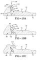
- the lips 82, 84 are then stitched together in a rolling operation wherein a roller (not shown) presses the lips 82, 84 into the closed orientation shown in FIGS. 6 and 8 and become entrapped within the chafer strip by a folding over the chafer strip over the top as seen in FIG. 10C .
- the angle ⁇ of the channel 80 with respect to a bottom surface of the chafer strip enables a complete capture of the coated filament 104 within the tire component, chafer 28, entirely surrounded by the chafer strip material composition.
- the channel 80 is destined to become the tube component to a peristaltic pump assembly within the tire chafer 70 and generally extends from chafer strip end 96 to end 98.
- the chafer is cut at a given length depending on the pump length that is desired when the tire is cured.
- Formed within each end of the chafer by a punching operation or cutting operation are enlarged diameter circular holes 100, 102.
- the holes 100, 102 are adjacent the ends of the channel 80 and are sized to accommodate receipt of peristaltic pump inlet and outlet devices (not shown).
- the lips 82,84 of the chafer channel 80 are pulled apart
- the coated filament 104 is inserted at direction arrow 110 into the channel 80 as shown in FIGS. 10A through 10C until adjacent and contacting the lower wall 86 of the channel 80.
- the coated filament 104 is enclosed by the chafer by a folding over of the chafer lip flap 82 in direction 112.
- the channel 80 is thus closed and subsequently stitched in the closed position by a pair of pressure contact rollers (not shown). So enclosed, the coated filament 104 will preserve the geometry of the channel 80 from green tire build until after tire cure when the coated filament 104 is removed.
- the coated filament 104 is dimensioned such that ends 106, 108 extend free from the chafer strip 70 and the chafer strip channel 80, and extend a distance beyond the punched holes 100, 102 at opposite ends of the chafer strip.
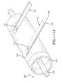
- a conventional green tire building station is depicted to include a build drum 116 rotational about an axial support 118.
- the chafer strip 70 containing coated filament 104 and an opposite chafer strip 122 that does not incorporate a coated filament 104 are positioned along opposite sides of the build drum 116 in direction 124 in an initial 180 degree chafer build-up.
- the chafer strip 70 is thus combined with a normal chafer strip 126 length to complete the circumference.
- the second strip 126 is applied to the building drum in alignment with and abutting strip 70 as shown in FIG. 11B to complete a 360 degree chafer construction on the drum.
- the opposite side of the drum receives two 180 degree normal strips 122 in abutment to complete the chafer build on that side.
- the chafer strip 70 contains the coated filament while the abutting strip 126 does not.
- both of the chafer strips 70, 126 as well as one or both of the strips 122 may be configured to contain a coated filament 104 to create a 360 degree peristaltic pump tube on one side or both sides of the green tire.
- the embodiment shown creates a pumping tube of 180 degree extent in one chafer component only.
- chafer strip 126 is configured to complement the construction of strip 70 shown in FIGS. 8 and 9 .
- Circular punch holes 100, 102 are at opposite ends of the complementary strip 126. When abutted against the strip 70, the punch holes 100, 102 create 180 degree opposite cavities 132, 134 as seen in FIGS. 13A and 13B .
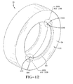
- FIG. 12 illustrates the 180 degree extension of the coated filament 104 and FIGS. 13A , 13B show the relative location of the coated filament 104 to the lower tire bead and apex components.
- FIG. 13A shows the inlet cavity 132 and coated filament 104 ready for placement of a temporary inlet core device and FIG. 13B shows the outlet cavity 134 ready for placement of a temporary outlet core device.
- FIGS. 14A through 14D show a first embodiment of a pre-cure, temporary outlet core assembly 136 with attached screw punch 138 and replacement nut 140.
- the temporary outlet core assembly 136 includes mating bottom half-housing component 142 and a top half-housing component 144 connecting by means of a coupling screw 160.
- the bottom half-housing component 142 has a dependent cylindrical screw threaded sleeve 146; an upper socket 148 extending downward into the component 142 and communicating with the upward facing opening of sleeve 146; and a half-protrusion 150 having an axial half-channel formed to extend across housing 142.
- the top-half-housing component 144 has a central through bore 154, a half-protrusion housing 156 and a half-channel formed to extend side to side across an underside of the housing 144.
- the two half-housing components 142, 144 are assembled by screw 160 threading bolt 162 down through the bore 154 and into the sleeve 146. So assembled, the half-protrusion housings 150 and 156 unite as well as the half-channels 152, 158. In the assembled state, as seen in FIGS.
- the protrusion housings 150, 156 form an outwardly projecting conical tube-coupling protrusion 164 away from the combined housing halves 142, 144 and defining an axial air passageway channel 165 having a sectional shape and dimension corresponding with the coated filament 104 within chafer strip 126 of the tire.
- the inwardly and outwardly threaded shaft 146 of the temporary outlet core assembly 136 receives and couples with an externally threaded shaft 168 of the screw punch accessory device 138.
- screw punch device 138 will in the course of peristaltic tube assembly formation be replaced with the threaded collar or nut 140 as shown in FIG. 14B .
- a metallic first embodiment of a precure, temporary inlet core assembly 170 is shown forming a housing body 174 from which a conical coupling housing protrusion 172 extends.
- An axial air passageway through-channel 176 extends through the housing body 174 and the protrusion 172 having a sectional shape and dimension corresponding with the shape and dimensions of the coated filament 104 within the chafer strip 126 of the green tire.
- the housing body 175 is formed by a combination of half-housing 178, 180, each providing a half-coupling protrusion 182, 194, respectively in which a half-channel 184, 196 is formed, respectively.
- a central assembly socket 186 extends into the internal underside of half-body 178 and receives an upright post 188 from the lower half-body 180 to center and register the two half-bodies together.
- Three sockets 190 are formed within the lower half-body 180 with each socket receiving a magnetic insert 192.
- the magnets 192 operate to secure the metallic half-housings 178 and 180 together.
- a threaded elbow and valve housing assembly 198 is shown for use as a permanent outlet core valve assembly.
- the housing assembly 198 is formed of a suitable material such as a nylon resin.
- the assembly 198 includes an elbow housing 200 having a conical remote end 202 and a cylindrical valve housing 204 affixed to an opposite end.
- a one-way valve such as a Lee valve, is housed within the valve housing 204.
- An axial air passageway 208 extends through the L-shaped assembly 198 and through the Lee valve seated in-line with the passageway.
- a Lee valve is a one-way valve which opens at a prescribed air pressure to allow air to pass and is commercially available from The Lee Company USA, located at Westbrook, CT, USA.
- FIGS. 17A and 17B show an alternative embodiment of an elbow connector and one-way post-cure outlet valve assembly 210.
- a L-shaped elbow connector housing 212 has a conical forward arm end 214 and an axial passageway 216 that extends through the L-shaped housing 212.
- the valve 218 has a circumferential array of air passages 227 that allow the passing of air from the housing of the valve.
- the valve 218 includes an umbrella stop member 222 having a frustro-conical depending protrusion 224 that fits and locks within a valve central bore 226 and a flexible circular stop membrane 223.
- the protrusion 224 of stop member 222 locks into the axial bore 226.
- the flexible membrane 223 is in a closed or down position when air pressure on the membrane is at or greater than a prescribed pressure setting. In the down position, membrane 223 covers the apertures 227 of the valve body and prevents air from passing.
- the membrane 223 moves to an up or open position when the air pressure outside the membrane falls to a pressure less than the preset pressure setting. In the up or open position, air can flow from the apertures 227 into the tire cavity.
- FIGS. 18A through 18D represent sequential views showing the installation of the inlet core assembly embodiment of FIGS. 15A through 15C connecting into the green tire coated filament 104 after green tire build and prior to curing of the green tire.
- the bottom half housing component 180 is inserted into the inlet cavity 132 after the cavity 132 has been enlarged into generally a key shape as indicated by the scissor representation.
- the cutting implement opens the chafer strip groove, still occupied by coated filament 104, to accommodate receipt of the conical half-protrusion 194 of half-housing 180.
- the tapered end of conical half-protrusion 194 fits into the chafer channel occupied by coated filament 104 as shown in FIG.
- the coated filament 104 is position within the half-channel 196 across the housing 180.
- the extra length of inlet end portion 108 is cut and removed, whereby positioning a terminal end of the coated filament 104 within the housing component 180.
- the upper, outer, top half-housing component 178 is thereupon assembled over the housing component 180, as seen in FIG. 18D , capturing the coated filament 104 within the channel formed by upper and lower half-channels 184, 196.
- the magnets 192 secure the metallic half-housings 178, 180 together. Rubber patches 228, 230 as seen in FIG. 18D are applied over the temporary inlet core assembly 170 to secure the assembly in place for the tire cure cycle.
- the hollow metallic housings 178, 180 are held together by the magnets. It will be appreciated that a non-metallic hollow housing may be employed if desired, such as a hollow housing made of molded plastic, with housing components held together by locking detent techniques known in the plastic casing art.
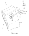
- FIGS. 19A through 19I show sequential assembly of the outlet core assembly embodiment of FIGS. 14A through 14D into the green tire outlet cavity 134 and to the outlet end portion 106 of the coated filament 104.
- the bottom half-component 142 is inserted into the cavity 134 after the circular cavity 134 has been enlarged into a keyhole configuration to accommodate the geometry of the component 142.
- the screw punch 138 is pushed through to protrude through tire wall into the tire cavity 20 from the cavity 134 as seen in FIG. 19C .
- FIG. 19A shows sequential assembly of the outlet core assembly embodiment of FIGS. 14A through 14D into the green tire outlet cavity 134 and to the outlet end portion 106 of the coated filament 104.
- the bottom half-component 142 is inserted into the cavity 134 after the circular cavity 134 has been enlarged into a keyhole configuration to accommodate the geometry of the component 142.
- the screw punch 138 is pushed through to protrude through tire wall into the tire cavity 20 from the cavity 134 as seen in FIG.
- FIG. 19B shows the component 142 fully seated into the cavity 134, the tapered conical half-protrusion 159 projecting into the chafer channel occupied by coated filament 104 with the coated filament 104 residing within half-channel 152.
- the screw punch 138 is removed and replaced by the nut 140 attached to the screw thread 146.
- the outlet end portion 106 of coated filament 104 is cut to length at the outlet cavity 134 and placement of the outlet top half-housing 144 over the bottom half-housing 142 within cavity 134.
- the screw 160 is threaded at 162 into socket 148 to affix both half-housings 142, 144 together as shown in FIGS. 19G and 19H .
- a rubber patch 234 is affixed over the outlet core assembly 136 in place for tire cure.
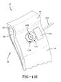
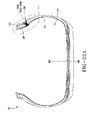
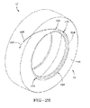
- FIGS. 20 , 21A , 21 B, 22A and FIG. 22B show the tire with the inlet and outlet temporary core assemblies in place before curing.
- the coated filament 104 enclosed within a chafer component 28 of the green tire extends 180 degrees between the pre-cure outlet core assembly 136 and the pre-cure inlet core assembly 170.
- An enlarged depiction of the inlet core location is shown in FIG. 21 B from section view FIG. 21A and the outlet core location is shown enlarged in FIG. 22B from the section view of FIG. 22A .
- the coated filament 104 resides enclosed within the chafer channel and thereby preserves the structural integrity of the chafer channel through tire cure.
- the sectional configuration of the coated filament 104 is complementary to chafer channel in which it is encased surrounded by chafer composition, and thereby maintains the configuration of the chafer channel throughout tire cure.
- FIG. 23 the post-cure removal of the half-housings 178, 180 from the inlet cavity 132 is shown.
- the cavity 132 is thus opened including a funnel-shaped cavity portion 233.
- FIGS. 24 and 25 show the nut 140 removed from the outlet core threaded shaft 146 to initiate a post-cure removal of the outlet core assembly 136.
- the assembly components 142, 144 are removed from the outlet cavity 134, leaving the cavity 134 including funnel-shaped adjacent cavity portion 237 open. Thereafter, as shown by FIG.
- the coated filament 104 is removed from the tire chafer channel, whereby the chafer channel left by the vacated coated filament 104 becomes an elongate unobstructed 180 degree air passageway 238 from the inlet cavity 132 to the outlet cavity 134, wholly integrated within the chafer component 28.
- Removal of the coated filament 104 as indicated in FIG. 26 is shown as a complete removal of the filament with the associated coating. In fact, while the filament is entirely removed, in some embodiments at least part of the coating material may remain adhered to the interior surfaces of the air passageway 238. The amount of coating material remaining in the air passageway 238 is insufficient to block the passage of air and the air passageway remains unobstructed and usable for its intended purpose as a peristaltic tube.
- the coated filament is constructed of a relatively thin filament coated with a coating material that is at least partially dispersible in the rubber of the rubber component during the cure heating cycle. That is, the coating material comprises one or more substances that may at least partially dissolve or otherwise combine with the rubber compound of the rubber component during the cure heating cycle. By so partially dispersing in the rubber of the rubber component, the coating is at least partially disengaged from the surface of the filament, thus facilitating removal of the filament from channel and creating the air passageway.
- the relatively thin filament is an elongate body of relatively constant cross section.
- Suitable cross sections for the filament are not limited, and include circular, oval, lens, and the like.
- Suitable filaments include those made of metal and polymers. Suitable metals include steel. Suitable polymers include thermoplastics, silicone rubber, and the like.
- Thermoplastics suitable for use as filaments include polyamides, polyesters, and poly(vinyl alcohols). Included in the polyamides are nylon 6, nylon 66, nylon 612, among others. Included in the polyesters are polyethylene terephthalate and polyethylene naphthalate, among others.
- the filament has a relatively circular cross section. In one embodiment, the filament has a diameter ranging from 0.5 to 5 mm.
- the filament is a so-called nylon monofilament.
- the coating material used for coating the filament comprises one or more substances that may at least partially disperse or otherwise combine with the rubber compound of the rubber component during the cure heating cycle.
- the rubber dispersible substances include oils, waxes, and rubber softeners.
- the coating material may include an oil.
- Suitable oils include aromatic, paraffinic, naphthenic, vegetable oils, and low PCA oils, such as MES, TDAE, SRAE and heavy naphthenic oils.
- Suitable low PCA oils include those having a polycyclic aromatic content of less than 3 percent by weight as determined by the IP346 method. Procedures for the IP346 method may be found in Standard Methods for Analysis & Testing of Petroleum and Related Products and British Standard 2000 Parts, 2003, 62nd edition, published by the Institute of Petroleum, United Kingdom .
- Suitable vegetable oils include canola (rapeseed) oil, sunflower oil, soybean oil, castor oil, and the like.
- the coating material may include a wax.
- Suitable waxes include synthetic (e.g. polyethylene and Fischer-Tropsch waxes) and natural (candelilla carnauba, beeswax, rice bran or mixtures thereof) and petroleum (e.g. microcrystalline and paraffin).
- the coating material may include rubber softeners.
- Rubber softeners include tallow, hydrogenated tallow, glycerol monostearate, glycerol triacetate, lecithin, mono-, diglycerides and triglycerides, acetylated glycerides and fatty acids having 16 to 18 carbon atoms (e.g. stearic, palmitic, oleic, linoleic and linolenic acids), fatty acid esters, fatty alcohols, fatty amides or mixtures thereof. Suitable fatty acid esters, fatty alcohols, and fatty amides include those disclosed in US-B- 7,231,951 .
- the coating material includes a mixture of one or more fatty acids having 16 to 18 carbon atoms.
- a mixture may include one or more or stearic, palmitic, oleic, linoleic and linolenic acids.
- Typical of such fatty acid blends is technical grade "rubber makers" stearic acid typically containing approximately 56 percent by weight stearic acid, 29 percent by weight palmitic acid, 8 percent by weight oleic acid and 7 percent by weight other fatty acids.
- the coating material may include, in addition to the dispersible material, a diluent.
- Diluents may be present to dilute the dispersable substances to reduce the viscosity. Suitable diluents include hydrocarbon solvents including tetrhydrofuran, hexane, cyclohexane, and the like. Other diluents include alcohols such as ethanol and propanol, and carboxylic acids such as acetic acid. The diluent may be present in an amount ranging from 1 to 50 parts by weight.
- the coating material may include, in addition to the dispersible material, a solid lubricant.
- Suitable solid lubricants include graphite, talc, and the like.
- the solid lubricant may be present in the coating material in an amount ranging from 1 to 30 parts by weight.
- the coating material is deposited on the surface of the filament in the form of a melt which is subsequently solidified to form the coating.
- the coating material is deposited on the surface of the filament in the form of a solution, with subsequent drying to remove volatile solvents or other diluents.
- the coating material is disposed on the outer surface of the filament by exposing the filament to the coating material.
- the coating may be disposed on the outer surface of the filament variety of processes, including dipping, spraying, brushing, wiping and the like.
- an elastomer overcoat over the coating material, especially in the case where a dry lubricant is included.
- Use of a dry lubricant may result in migration of the dry lubricant into the splice formed upon closure of walls 82, 84 around coated filament 104 (see FIGS. 10A, 10B, and 10C ). Such migration of dry lubricant is undesirable as it may lead to weakening of the interface between walls 82, 84.
- the elastomer overcoat may be applied, for example, by dipping the coated filament into a elastomer latex, followed by drying in air.
- Suitable elastomer latex may include latex of natural rubber, styrene-butadiene rubber, and styrene-butadiene-vinylpyridine rubber.
- SWAT Standard wire adhesion tests
- Composition SWAT Pull-Out force N 1 Rapeseed Oil/Ethanol 81 2 Castor Oil/Ethanol 81 3 Ethanol 76 4 Rapeseed Oil/Acetic Acid 45 5 Control 82 6 Castor Oil/Acetic Acid 44 7 Acetic Acid 32 8 Fatty Acid 1 /THF 80 9 Wax (Melt) 68 10 Fatty Acid 1 (Melt) 41 11 Fatty Acid 1 /Graphite (Melt) 20 12 Fatty Acid 1 /Talc (Melt) 32 13 Fatty Acid 1 /Graphite/THF 20 14 Fatty Acid 1 /Talc/THF 27 1 A blend of fatty acids containing approximately 56 percent by weight stearic acid, 29 percent by weight palmitic acid, 8 percent by weight oleic acid and 7 percent by weight other fatty acids.
- Nylon monofilament was coated with a melt of fatty acid and 20 weight percent graphite as described in Example 2. The coating monofilament was then further dipped in a low ammonia natural rubber latex. The latex was allowed to air dry at 60 C, forming a natural rubber (NR) layer over the fatty acid/graphite layer.
- NR natural rubber
- SWAT adhesion tests were performed on various samples following the procedure of Example 1, with the exception that the embedded length of the monofilament was 21 cm. Results of the SWAT adhesion tests are given in Table 4.
Landscapes
- Engineering & Computer Science (AREA)
- Textile Engineering (AREA)
- Mechanical Engineering (AREA)
- Chemical & Material Sciences (AREA)
- Chemical Kinetics & Catalysis (AREA)
- Tyre Moulding (AREA)
- Tires In General (AREA)
Abstract
Description
- Normal air diffusion reduces tire pressure over time. The natural state of tires is under inflated. Accordingly, drivers must repeatedly act to maintain tire pressures or they will see reduced fuel economy, tire life and reduced vehicle braking and handling performance. Tire Pressure Monitoring Systems have been proposed to warn drivers when tire pressure is significantly low. Such systems, however, remain dependant upon the driver taking remedial action when warned to re-inflate a tire to recommended pressure. It is a desirable, therefore, to incorporate an air maintenance feature within a tire that will re-inflate the tire in order to compensate for normal air diffusion over time without the need for driver intervention.
- The present invention is directed to a method in accordance with
claim 1. Dependent claims refer to preferred embodiments of the invention. - In a preferred aspect of the invention, the method is a method of constructing a tire, comprising:
- constructing a coated filament, the coated filament constructed by coating a filament with a coating material, the coating material comprising at least one substance dispersible in an uncured rubber compound;
- encasing the coated filament into containment within an uncured flexible tire component, the coated filament extending between an air inlet and an air outlet cavity in the flexible tire component;
- building on a tire building drum a green tire carcass from uncured tire components including the uncured flexible tire component and encased coated filament;
- curing the green tire carcass into a cured finished tire including the flexible tire component containing the coated filament;
- removing the filament from the cured flexible tire component to leave within the flexible tire component a substantially unobstructed air passageway.
- The term "filament" as used herein shall include the term "wire" or "cable", i.e. the filament may be a wire or a cable.
- In a preferred aspect of the invention, the substantially unobstructed passageway is a substantially unobstructed air passageway extending between an air inlet and an air outlet cavity after curing.
- In a preferred aspect of the invention, the green tire component assembly is a green tire carcass. I may however also be a green tire apex, a green tire tread or a green tire shoulder component.
- In a preferred aspect of the invention, the green tire component assembly is built on a tire building drum.
- In a preferred aspect of the invention, the uncured flexible tire component is a tire chafer component. It may however also be a tire apex component, a tire tread component or a tire shoulder component.
- "Aspect ratio" of the tire means the ratio of its section height (SH) to its section width (SW) multiplied by 100 percent for expression as a percentage.
- "Axial" and "axially" means lines or directions that are parallel to the axis of rotation of the tire.
- "Chafer" is a strip of material placed around the outside of a tire bead to protect the cord plies from wearing and cutting against the rim and distribute the flexing above the rim.
- "Circumferential" means lines or directions extending along the perimeter of the surface of the annular tread perpendicular to the axial direction.
- "Equatorial Centerplane (CP)" means the plane perpendicular to the tire's axis of rotation and passing through the center of the tread.
- "Footprint" means the contact patch or area of contact of the tire tread with a flat surface at zero speed and under normal load and pressure.
- "Groove" means an elongated void area in a tire wall that may extend circumferentially or laterally about the tire wall. The "groove width" is equal to its average width over its length. A groove is sized to accommodate an air tube as described.
- "Inboard side" means the side of the tire nearest the vehicle when the tire is mounted on a wheel and the wheel is mounted on the vehicle.
- "Lateral" means an axial direction.
- "Lateral edges" means a line tangent to the axially outermost tread contact patch or footprint as measured under normal load and tire inflation, the lines being parallel to the equatorial centerplane.
- "Net contact area" means the total area of ground contacting tread elements between the lateral edges around the entire circumference of the tread divided by the gross area of the entire tread between the lateral edges.
- "Outboard side" means the side of the tire farthest away from the vehicle when the tire is mounted on a wheel and the wheel is mounted on the vehicle.
- "Peristaltic" means operating by means of wave-like contractions that propel contained matter, such as air, along tubular pathways.
- "Radial" and "radially" means directions radially toward or away from the axis of rotation of the tire.
- "Tread Arc Width" means the arc length of the tread as measured between the lateral edges of the tread.
- The invention will be described by way of example and with reference to the accompanying drawings in which:
-
FIG. 1 is a detail view of the filament die. -
FIG. 2 is a perspective view of a basic filament extruder and conveyor. -
FIG. 3 is a detail of a chafer die. -
FIG. 4 is a perspective view of a basic chafer strip extruder and conveyor. -
FIG. 5 is a dimensioned sectioned view of the filament. -
FIG. 6 is a dimensioned sectioned view of extruded chafer strip. -
FIG. 7A is a schematic representation of a process to dip the filament in a coating material. -
FIG. 7B is a perspective of the coated filament. -
FIG. 8 is a detail view of the chafer strip with punched hole locations. -
FIG. 9 is an enlarged perspective view of the coated filament being assembled into the chafer strip. -
FIGS. 10A through 10C are sectioned views showing the coated filament and the chafer strip assembly. -
FIG. 11A is a perspective view of a tire build up drum with assembled 180 degree filament/chafer strip being applied, with a normal chafer strip placement on opposite ends. -
FIG. 11B is a perspective view of a tire build up drum with a normal 180 degree chafer strip being placed abutting the 180 degree filament/chafer strip. -
FIG. 12 is a perspective front view of a formed green tire showing inlet and outlet locations with the coated filamant extending from openings and the tire ready for core forming devices. -
FIG. 13A is an enlarged sectioned view showing the inlet cavity and the coated filament ready for placement of the inlet core device. -
FIG. 13B is an enlarged sectioned view showing the outlet cavity and the coated filament ready for placement of the outlet core device. -
FIG. 14A is a top perspective view showing a first embodiment outlet core assembly with screw punch attached. -
FIG. 14B is a bottom perspective view showing the outlet core assembly with screw punch removed and the nut attached. -
FIG. 14C is a top exploded view of the outlet core assembly showing top/bottom core halves and mounting screw with the screw punch and hold down nut. -
FIG. 14D is a bottom exploded view ofFIG. 14C . -
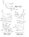
FIG. 15A is a top perspective view of a first embodiment inlet core assembly. -
FIG. 15B is a top exploded view of the inlet core assembly showing top/bottom core halves and magnetic inserts. -
FIG. 15C is a bottom exploded view ofFIG. 15B . -
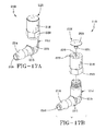
FIG. 16A is a threaded elbow and valve housing assembly. -
FIG. 16B is an exploded view ofFIG. 16A showing the elbow, valve housing and Lee valve. -
FIG. 17A shows an alternative embodiment of threaded elbow and one-way valve assembly. -
FIG. 17B is an exploded view ofFIG. 17A showing the elbow valve housing with air passage ways and membrane cover. -
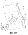
FIG. 18A is an enlarged sectioned view showing the inlet bottom core being inserted into the cavity under the coated filament and the chafer groove re-opened to allow room of the conical end of the inlet core to be fully seated into cavity. -
FIG. 18B is an enlarged sectioned view showing the inlet bottom core fully inserted into the cavity and the coated filament being trimmed to length. -
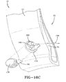
FIG. 18C is an enlarged sectioned view showing the inlet top core ready for placement into the cavity. -
FIG. 18D is an enlarged section view showing the inlet core assembly fully assembled into cavity. -
FIG. 18E is an enlarged section view showing the inlet core assembly held in place with thin rubber patches is ready for curing. -
FIG. 19A is an enlarged sectioned view showing the outlet bottom core unit being inserted into the cavity under the coated filament and the punch forced through the tire wall into the cavity chamber with the chafer groove re-opened to allow room for the conical end of the outlet core bottom unit to be fully seated into cavity. -
FIG. 19B is an enlarged sectioned view of the bottom outlet core unit fully seated into the cavity. -
FIG. 19C is an enlarged sectioned view from cavity side showing the screw punch fully inserted through the tire wall. -
FIG. 19D is an enlarged sectioned view of the screw punch removed from the outlet bottom core half component with the nut attached to thread shaft. -
FIG. 19E is an enlarged sectioned view showing the nut fully attached to the outlet bottom core shaft. -
FIG. 19F is an enlarged sectioned view of the coated filament cut to length at the outlet bottom core strip cavity. -
FIG. 19G is an enlarged sectioned view of the outlet top core component placed into the cavity and screwed into place. -
FIG. 19H is an enlarged sectioned view showing the outlet core halves and screw fully assembled. -
FIG. 19I is an enlarged sectioned view showing the conical end of outlet core assembly covered with a rubber patch. -
FIG. 20 is a side view of a tire showing the inlet and outlet core locations before curing. -
FIG. 21A is a section view taken fromFIG. 20 showing the inlet core location. -
FIG. 21 B is an enlarged view of the inlet core taken fromFIG. 21A . -
FIG. 22A is a section view taken fromFIG. 20 showing the outlet core. -
FIG. 22B is an enlarged view of the outlet core taken fromFIG. 22A . -
FIG. 23 is an enlarged sectioned view showing the inlet core halves being removed after curing. -
FIG. 24 is an enlarged sectioned view showing the nut removed from the outlet core threaded shaft. -
FIG. 25 is an exploded view of the outlet core halves disassembled and removed from the sidewall cavity. -
FIG. 26 is a side elevation showing the coated filament removed from the tire sidewall. - In one embodiment of the invention, there is disclosed a method of constructing a tire or of providing a passage way in a tire, comprising:
- constructing a coated filament, the coated filament constructed by coating a filament with a coating material, the coating material comprising at least one substance dispersible in an uncured rubber compound;
- encasing the coated filament into containment within an uncured flexible tire component, the coated filament extending between an air inlet and an air outlet cavity in the uncured flexible tire component;
- building on a tire building drum a green tire carcass from uncured tire components including the uncured flexible tire component and encased coated filament;
- curing the green tire carcass into a cured finished tire including the flexible tire component containing the coated filament;
- removing the filament from the cured flexible tire component to leave within the flexible tire component a substantially unobstructed air passageway.
- With reference to
FIGS. 1, 2 ,3 ,4 ,5 and 6 , apolymer filament 58 is formed by means of die 48 having a profiledorifice 50 therethrough. The orifice is elongate and generally lens shaped in section with the extrudedstrip 58 of like sectional geometry. The lens shape may have a dimension of, by way of example without limitation intent, 2.7 mm length D2 x 0.5 mm at D1. While the preferred composition of thestrip 58 is a polymer, other materials such as cable may be used if desired. Thedie 48 is affixed to a basic extruder of conventional configuration and deposits a formedfilament 58 on a conveyer belt moved bydrive roller 56. Thefilament 58 may be wound on a spool (not shown) for further processing and will be shown. As shown inFIGS. 3 and4 , achafer strip 70 is formed by extrusion die 60 affixed toextruder 66 and deposited onroller 68. Thedie 60 is formed having along achafer forming opening 62 along a bottom side and adownward projection finger 64 projecting into theopening 62.FIG. 6 shows a sectioned view of the extruded chafer strip. As seen, thestrip 70 widens in section from a low width orthinner end region 72 to a stepped wider orthicker region 74 to a wider or thickeropposite region 88. Thedie finger 64 forms an incut, arching chafer channel ortube 80 extending the length of the chafer strip, defined bychannel sidewalls bottom wall 86. The channel is open initially as shown at 90. The chafer strip dimensions may be varied to suit the particular tire sizing needs and the tire construction characteristics desired. - A flexible tire component, such as a chafer segment, is provided with a
groove 80, as best seen in section fromFIG. 6 , is defined bygroove lips bottom groove wall 86. Thegroove 80, formed within an axially outwardthicker side 88 of the chafer strip is accordingly open atgroove opening 90. Thegroove 80 formed within the chafer as a result angles axially outward from theopening 90 to thebottom wall 86 at an acute angle θ. As shown inFIG. 7A ,coated filament 104 is constructed withfilament 58 enveloped withincoating 92 formed of a material as will be described later. Thecoated filament 104, as explained following, will be used to form peristaltic tube within a green tire during green tire construction. - As shown in
FIG. 7A and 7B , thefilament 58 is treated with acoating 92 to facilitate pull out from the chafer, as will be shown. As seen inFIG. 7A , thecoating material 92 is disposed on the outer surface of thefilament 58 by dipping thefilament 58 in thecoating material liquid 392. With reference now toFIG. 7A , one embodiment of a method of coating a filament according to the present invention is illustrated, whereinliquid coating material 392 is held in adip bath 322.Liquid coating material 392 is in liquid form, either as a solution or a melt.Filament 58 is unwound fromspool 330 and conveyed throughdip bath 322 andliquid coating material 392 for deposition ofliquid coating material 392 onto the surface offilament 58. Cooling or drying means (not shown) may be included afterdip bath 322 to facilitate drying and/or solidification of theliquid coating material 392 after deposition, resulting incoated filament 104 havingcoating material 92 on the outside offilament 58.Coated filament 104 exits dipbath 322 and is wound ontospool 32 for storage after any cooling or drying (not shown). - The general purpose of
coated filament 104 is to form within a green tire component, such aschafer 28, a core air passageway which, once the filament is removed, forms a peristaltic tube integrally within and enclosed by the tire component. Theangled groove 80 is formed within the chafer strip as a slot, with thelips groove 80 is then opened to receive thecoated filament 104 by an elastic spreading apart ofgroove lips coated filament 104 is positioned downward into thegroove 80 until reaching a position adjacent to thebottom wall 86. A release of thelips lips lips FIGS. 6 and8 and become entrapped within the chafer strip by a folding over the chafer strip over the top as seen inFIG. 10C . The angle θ of thechannel 80 with respect to a bottom surface of the chafer strip enables a complete capture of thecoated filament 104 within the tire component,chafer 28, entirely surrounded by the chafer strip material composition. - With reference to
FIGS. 8 ,9 ,10A through 10C and7B , thechannel 80 is destined to become the tube component to a peristaltic pump assembly within thetire chafer 70 and generally extends fromchafer strip end 96 to end 98. The chafer is cut at a given length depending on the pump length that is desired when the tire is cured. Formed within each end of the chafer by a punching operation or cutting operation are enlarged diametercircular holes holes channel 80 and are sized to accommodate receipt of peristaltic pump inlet and outlet devices (not shown). Thelips chafer channel 80 are pulled apart Thecoated filament 104 is inserted atdirection arrow 110 into thechannel 80 as shown inFIGS. 10A through 10C until adjacent and contacting thelower wall 86 of thechannel 80. Thereupon, thecoated filament 104 is enclosed by the chafer by a folding over of thechafer lip flap 82 indirection 112. Thechannel 80 is thus closed and subsequently stitched in the closed position by a pair of pressure contact rollers (not shown). So enclosed, thecoated filament 104 will preserve the geometry of thechannel 80 from green tire build until after tire cure when thecoated filament 104 is removed. Thecoated filament 104 is dimensioned such that ends 106, 108 extend free from thechafer strip 70 and thechafer strip channel 80, and extend a distance beyond the punchedholes - Referring to
FIGS. 11A ,11 B and 12 , a conventional green tire building station is depicted to include abuild drum 116 rotational about anaxial support 118. Thechafer strip 70 containingcoated filament 104 and anopposite chafer strip 122 that does not incorporate acoated filament 104 are positioned along opposite sides of thebuild drum 116 indirection 124 in an initial 180 degree chafer build-up. Thechafer strip 70 is thus combined with anormal chafer strip 126 length to complete the circumference. Thesecond strip 126 is applied to the building drum in alignment with and abuttingstrip 70 as shown inFIG. 11B to complete a 360 degree chafer construction on the drum. The opposite side of the drum receives two 180 degreenormal strips 122 in abutment to complete the chafer build on that side. It will be noted that thechafer strip 70 contains the coated filament while theabutting strip 126 does not. However, if desired, both of the chafer strips 70, 126 as well as one or both of thestrips 122 may be configured to contain acoated filament 104 to create a 360 degree peristaltic pump tube on one side or both sides of the green tire. For the purpose of explanation, the embodiment shown creates a pumping tube of 180 degree extent in one chafer component only. InFIG. 11B it will be noted thatchafer strip 126 is configured to complement the construction ofstrip 70 shown inFIGS. 8 and9 . Circular punch holes 100, 102 are at opposite ends of thecomplementary strip 126. When abutted against thestrip 70, the punch holes 100, 102 create 180 degreeopposite cavities FIGS. 13A and13B . - The
free end 106 for the purpose of explanation will hereafter be referred to as the "outlet end portion" of thecoated filament 104 extending through theoutlet cavity 134; and thefree end 108 the "inlet end portion" of thecoated filament 104 extending through thecircular inlet cavity 132.FIG. 12 illustrates the 180 degree extension of thecoated filament 104 andFIGS. 13A ,13B show the relative location of thecoated filament 104 to the lower tire bead and apex components.FIG. 13A shows theinlet cavity 132 andcoated filament 104 ready for placement of a temporary inlet core device andFIG. 13B shows theoutlet cavity 134 ready for placement of a temporary outlet core device. -
FIGS. 14A through 14D show a first embodiment of a pre-cure, temporaryoutlet core assembly 136 with attachedscrew punch 138 andreplacement nut 140. The temporaryoutlet core assembly 136 includes mating bottom half-housing component 142 and a top half-housing component 144 connecting by means of acoupling screw 160. The bottom half-housing component 142 has a dependent cylindrical screw threadedsleeve 146; anupper socket 148 extending downward into thecomponent 142 and communicating with the upward facing opening ofsleeve 146; and a half-protrusion 150 having an axial half-channel formed to extend acrosshousing 142. The top-half-housing component 144 has a central throughbore 154, a half-protrusion housing 156 and a half-channel formed to extend side to side across an underside of thehousing 144. United as shown inFIGS. 14A and 14 B , the two half-housing components screw 160threading bolt 162 down through thebore 154 and into thesleeve 146. So assembled, the half-protrusion housings channels FIGS. 14A and 14B , theprotrusion housings coupling protrusion 164 away from the combinedhousing halves air passageway channel 165 having a sectional shape and dimension corresponding with thecoated filament 104 withinchafer strip 126 of the tire. - The inwardly and outwardly threaded
shaft 146 of the temporaryoutlet core assembly 136 receives and couples with an externally threadedshaft 168 of the screwpunch accessory device 138. As will be explained below, screwpunch device 138 will in the course of peristaltic tube assembly formation be replaced with the threaded collar ornut 140 as shown inFIG. 14B . - With reference to
FIGS. 15A through 15C , a metallic first embodiment of a precure, temporaryinlet core assembly 170 is shown forming a housing body 174 from which a conicalcoupling housing protrusion 172 extends. An axial air passageway through-channel 176 extends through the housing body 174 and theprotrusion 172 having a sectional shape and dimension corresponding with the shape and dimensions of thecoated filament 104 within thechafer strip 126 of the green tire. The housing body 175 is formed by a combination of half-housing coupling protrusion channel central assembly socket 186 extends into the internal underside of half-body 178 and receives anupright post 188 from the lower half-body 180 to center and register the two half-bodies together. Threesockets 190 are formed within the lower half-body 180 with each socket receiving amagnetic insert 192. Themagnets 192 operate to secure the metallic half-housings - Referencing
FIGS. 16A and 16B , a threaded elbow andvalve housing assembly 198 is shown for use as a permanent outlet core valve assembly. Thehousing assembly 198 is formed of a suitable material such as a nylon resin. Theassembly 198 includes anelbow housing 200 having a conicalremote end 202 and acylindrical valve housing 204 affixed to an opposite end. A one-way valve, such as a Lee valve, is housed within thevalve housing 204. Anaxial air passageway 208 extends through the L-shapedassembly 198 and through the Lee valve seated in-line with the passageway. A Lee valve is a one-way valve which opens at a prescribed air pressure to allow air to pass and is commercially available from The Lee Company USA, located at Westbrook, CT, USA. -
FIGS. 17A and 17B show an alternative embodiment of an elbow connector and one-way post-cureoutlet valve assembly 210. A L-shapedelbow connector housing 212 has a conicalforward arm end 214 and anaxial passageway 216 that extends through the L-shapedhousing 212. An umbrella-type valve 218 of a type commercially available from MiniValve International located in Oldenzaal, The Netherlands, attaches to a threaded end ofhousing 212 by means ofnut 220. Thevalve 218 has a circumferential array ofair passages 227 that allow the passing of air from the housing of the valve. Thevalve 218 includes anumbrella stop member 222 having a frustro-conical depending protrusion 224 that fits and locks within a valvecentral bore 226 and a flexiblecircular stop membrane 223. Theprotrusion 224 ofstop member 222 locks into theaxial bore 226. Theflexible membrane 223 is in a closed or down position when air pressure on the membrane is at or greater than a prescribed pressure setting. In the down position,membrane 223 covers theapertures 227 of the valve body and prevents air from passing. Themembrane 223 moves to an up or open position when the air pressure outside the membrane falls to a pressure less than the preset pressure setting. In the up or open position, air can flow from theapertures 227 into the tire cavity. -
FIGS. 18A through 18D represent sequential views showing the installation of the inlet core assembly embodiment ofFIGS. 15A through 15C connecting into the green tire coatedfilament 104 after green tire build and prior to curing of the green tire. InFIG. 18A , the bottomhalf housing component 180 is inserted into theinlet cavity 132 after thecavity 132 has been enlarged into generally a key shape as indicated by the scissor representation. The cutting implement opens the chafer strip groove, still occupied bycoated filament 104, to accommodate receipt of the conical half-protrusion 194 of half-housing 180. The tapered end of conical half-protrusion 194 fits into the chafer channel occupied bycoated filament 104 as shown inFIG. 18B , as thecoated filament 104 is position within the half-channel 196 across thehousing 180. The extra length ofinlet end portion 108 is cut and removed, whereby positioning a terminal end of thecoated filament 104 within thehousing component 180. The upper, outer, top half-housing component 178 is thereupon assembled over thehousing component 180, as seen inFIG. 18D , capturing thecoated filament 104 within the channel formed by upper and lower half-channels magnets 192 secure the metallic half-housings Rubber patches FIG. 18D are applied over the temporaryinlet core assembly 170 to secure the assembly in place for the tire cure cycle. The hollowmetallic housings -
FIGS. 19A through 19I show sequential assembly of the outlet core assembly embodiment ofFIGS. 14A through 14D into the greentire outlet cavity 134 and to theoutlet end portion 106 of thecoated filament 104. InFIG. 19A , the bottom half-component 142 is inserted into thecavity 134 after thecircular cavity 134 has been enlarged into a keyhole configuration to accommodate the geometry of thecomponent 142. Thescrew punch 138 is pushed through to protrude through tire wall into thetire cavity 20 from thecavity 134 as seen inFIG. 19C .FIG. 19B shows thecomponent 142 fully seated into thecavity 134, the tapered conical half-protrusion 159 projecting into the chafer channel occupied bycoated filament 104 with thecoated filament 104 residing within half-channel 152. InFIG. 19D and19E , thescrew punch 138 is removed and replaced by thenut 140 attached to thescrew thread 146. InFIG. 19F , theoutlet end portion 106 ofcoated filament 104 is cut to length at theoutlet cavity 134 and placement of the outlet top half-housing 144 over the bottom half-housing 142 withincavity 134. Thescrew 160 is threaded at 162 intosocket 148 to affix both half-housings FIGS. 19G and19H . Arubber patch 234 is affixed over theoutlet core assembly 136 in place for tire cure. -
FIGS. 20 ,21A ,21 B, 22A andFIG. 22B show the tire with the inlet and outlet temporary core assemblies in place before curing. As seen, thecoated filament 104 enclosed within achafer component 28 of the green tire extends 180 degrees between the pre-cureoutlet core assembly 136 and the pre-cureinlet core assembly 170. An enlarged depiction of the inlet core location is shown inFIG. 21 B from section viewFIG. 21A and the outlet core location is shown enlarged inFIG. 22B from the section view ofFIG. 22A . Thecoated filament 104 resides enclosed within the chafer channel and thereby preserves the structural integrity of the chafer channel through tire cure. The sectional configuration of thecoated filament 104, as seen, is complementary to chafer channel in which it is encased surrounded by chafer composition, and thereby maintains the configuration of the chafer channel throughout tire cure. - Referring to
FIG. 23 , the post-cure removal of the half-housings inlet cavity 132 is shown. Thecavity 132 is thus opened including a funnel-shapedcavity portion 233.FIGS. 24 and25 show thenut 140 removed from the outlet core threadedshaft 146 to initiate a post-cure removal of theoutlet core assembly 136. Theassembly components outlet cavity 134, leaving thecavity 134 including funnel-shapedadjacent cavity portion 237 open. Thereafter, as shown byFIG. 26 thecoated filament 104 is removed from the tire chafer channel, whereby the chafer channel left by the vacatedcoated filament 104 becomes an elongate unobstructed 180degree air passageway 238 from theinlet cavity 132 to theoutlet cavity 134, wholly integrated within thechafer component 28. - Removal of the
coated filament 104 as indicated inFIG. 26 is shown as a complete removal of the filament with the associated coating. In fact, while the filament is entirely removed, in some embodiments at least part of the coating material may remain adhered to the interior surfaces of theair passageway 238. The amount of coating material remaining in theair passageway 238 is insufficient to block the passage of air and the air passageway remains unobstructed and usable for its intended purpose as a peristaltic tube. - As inserted into the tire component, the coated filament is constructed of a relatively thin filament coated with a coating material that is at least partially dispersible in the rubber of the rubber component during the cure heating cycle. That is, the coating material comprises one or more substances that may at least partially dissolve or otherwise combine with the rubber compound of the rubber component during the cure heating cycle. By so partially dispersing in the rubber of the rubber component, the coating is at least partially disengaged from the surface of the filament, thus facilitating removal of the filament from channel and creating the air passageway.
- The relatively thin filament is an elongate body of relatively constant cross section. Suitable cross sections for the filament are not limited, and include circular, oval, lens, and the like. Suitable filaments include those made of metal and polymers. Suitable metals include steel. Suitable polymers include thermoplastics, silicone rubber, and the like.
- Thermoplastics suitable for use as filaments include polyamides, polyesters, and poly(vinyl alcohols). Included in the polyamides are nylon 6,
nylon 66, nylon 612, among others. Included in the polyesters are polyethylene terephthalate and polyethylene naphthalate, among others. - In one embodiment, the filament has a relatively circular cross section. In one embodiment, the filament has a diameter ranging from 0.5 to 5 mm.
- In one embodiment, the filament is a so-called nylon monofilament.
- The coating material used for coating the filament comprises one or more substances that may at least partially disperse or otherwise combine with the rubber compound of the rubber component during the cure heating cycle. The rubber dispersible substances include oils, waxes, and rubber softeners.
- The coating material may include an oil. Suitable oils include aromatic, paraffinic, naphthenic, vegetable oils, and low PCA oils, such as MES, TDAE, SRAE and heavy naphthenic oils. Suitable low PCA oils include those having a polycyclic aromatic content of less than 3 percent by weight as determined by the IP346 method. Procedures for the IP346 method may be found in Standard Methods for Analysis & Testing of Petroleum and Related Products and British Standard 2000 Parts, 2003, 62nd edition, published by the Institute of Petroleum, United Kingdom. Suitable vegetable oils include canola (rapeseed) oil, sunflower oil, soybean oil, castor oil, and the like.
- The coating material may include a wax. Suitable waxes include synthetic (e.g. polyethylene and Fischer-Tropsch waxes) and natural (candelilla carnauba, beeswax, rice bran or mixtures thereof) and petroleum (e.g. microcrystalline and paraffin).
- The coating material may include rubber softeners. Rubber softeners include tallow, hydrogenated tallow, glycerol monostearate, glycerol triacetate, lecithin, mono-, diglycerides and triglycerides, acetylated glycerides and fatty acids having 16 to 18 carbon atoms (e.g. stearic, palmitic, oleic, linoleic and linolenic acids), fatty acid esters, fatty alcohols, fatty amides or mixtures thereof. Suitable fatty acid esters, fatty alcohols, and fatty amides include those disclosed in
US-B- 7,231,951 . - In one embodiment, the coating material includes a mixture of one or more fatty acids having 16 to 18 carbon atoms. Such a mixture may include one or more or stearic, palmitic, oleic, linoleic and linolenic acids. Typical of such fatty acid blends is technical grade "rubber makers" stearic acid typically containing approximately 56 percent by weight stearic acid, 29 percent by weight palmitic acid, 8 percent by weight oleic acid and 7 percent by weight other fatty acids.
- The coating material may include, in addition to the dispersible material, a diluent. Diluents may be present to dilute the dispersable substances to reduce the viscosity. Suitable diluents include hydrocarbon solvents including tetrhydrofuran, hexane, cyclohexane, and the like. Other diluents include alcohols such as ethanol and propanol, and carboxylic acids such as acetic acid. The diluent may be present in an amount ranging from 1 to 50 parts by weight.
- The coating material may include, in addition to the dispersible material, a solid lubricant. Suitable solid lubricants include graphite, talc, and the like. The solid lubricant may be present in the coating material in an amount ranging from 1 to 30 parts by weight.
- The coating material is deposited on the surface of the filament in the form of a melt which is subsequently solidified to form the coating. Alternatively, the coating material is deposited on the surface of the filament in the form of a solution, with subsequent drying to remove volatile solvents or other diluents.
- The coating material is disposed on the outer surface of the filament by exposing the filament to the coating material. The coating may be disposed on the outer surface of the filament variety of processes, including dipping, spraying, brushing, wiping and the like.
- In one embodiment, it may be desirable to use an elastomer overcoat over the coating material, especially in the case where a dry lubricant is included. Use of a dry lubricant may result in migration of the dry lubricant into the splice formed upon closure of
walls FIGS. 10A, 10B, and 10C ). Such migration of dry lubricant is undesirable as it may lead to weakening of the interface betweenwalls - The invention is further illustrated by the following examples.
- In this example, the ability of a coated filament to be pulled out of a cured rubber sample is illustrated. Samples of a nylon monofilament of approximately circular cross section were dipped coated with a several different coating materials. Coating materials were prepared by mixing dispersible material, diluent, and dry lubricant with compositions of the coating materials as shown in Table 1. Single lengths of nylon monofilament were manually dipped in a prepared coating material contained in a test tube. After dipping, the coating material on the monofilament was allowed to dry in the case of deposition from solution, or solidify if deposited from a melt.
Table 1 Sample No. Dip Type Dispersible Wt,g Diluent Wt,g Lubricant Wt, g 1 Solution Rapeseed Oil 50 Ethanol 50 None 0 2 Solution Castor Oil 50 Ethanol 50 None 0 3 Solution None 0 Ethanol 100 None 0 4 Solution Rapeseed Oil 50 Acetic Acid 50 None 0 5 None None 0 None 0 None 0 6 Solution Castor Oil 50 Acetic Acid 50 None 0 7 Solution None 0 Acetic Acid 100 None 0 8 Solution Fatty Acid1 25 THF 275 None 0 9 Melt Wax 100 None 0 None 0 10 Melt Fatty Acid 1 100 None 0 None 0 11 Melt Fatty Acid1 84.4 None 0 Graphite 15.6 12 Melt Fatty Acid1 84.4 None 0 Talc 15.6 13 Solution Fatty Acid 1 20 THF 260 Graphite 20 14 Solution Fatty Acid 1 20 THF 260 Talc 20 1 A blend of fatty acids containing approximately 56 percent by weight stearic acid, 29 percent by weight palmitic acid, 8 percent by weight oleic acid and 7 percent by weight other fatty acids.
2 Tetrahydrofuran - Standard wire adhesion tests (SWAT) were conducted by embedding a coated monofilament in a green rubber composition. The embedded length of the monofilament was 7.5 cm. The rubber articles were then cured at 150 °C for 28 minutes. The monofilament in these rubber compositions were then subjected to a pull-out test, according to ASTM Standard D2229-73. The results of these pull-out tests (SWAT) and rubber coverage are given in Table 2 and expressed in Newtons.
Table 2 Sample No. Composition SWAT Pull-Out force, N 1 Rapeseed Oil/Ethanol 81 2 Castor Oil/Ethanol 81 3 Ethanol 76 4 Rapeseed Oil/Acetic Acid 45 5 Control 82 6 Castor Oil/Acetic Acid 44 7 Acetic Acid 32 8 Fatty Acid1/ THF 80 9 Wax (Melt) 68 10 Fatty Acid1 (Melt) 41 11 Fatty Acid1/Graphite (Melt) 20 12 Fatty Acid1/Talc (Melt) 32 13 Fatty Acid1/Graphite/ THF 20 14 Fatty Acid1/Talc/THF 27 1 A blend of fatty acids containing approximately 56 percent by weight stearic acid, 29 percent by weight palmitic acid, 8 percent by weight oleic acid and 7 percent by weight other fatty acids. - As seen in Table 2, the lowest pull-out force was seen using a combination of stearic acid and graphite, whether from a melt or THF solution.
- In this example, the effect of graphite content on the ability of a monofilament treated with a fatty acid melt is illustrated. Samples of nylon monofilament were dipped in a fatty acid melt as described in Example 1, with the coatings containing various amounts of graphite. The coated samples were embedded in rubber and tested for pullout force following the procedure in Example 1, with results given in Table 3.
Table 3 Sample No. Graphite Content, Weight Percent SWAT Pull-Out Force, N 14 0 26 15 0.6 31 16 1.08 29 17 2.1 21 18 5.08 19 19 10.06 13 20 20 8 - As seen in Table 3, the pull-out force steadily decreased with increasing graphite content.
- In this example, preparation of a tire with an air passage is illustrated. Continuous nylon monofilament was coated from a melt of fatty acid and 20 weight percent graphite by drawing the monofilament from a spool through a beaker of the melt, followed by solidification in air. The coated monofilament was then wound on a spool. Eighty cm lengths of the coated monofilament we embedded in a semi-circumferential slit made with a razor knife in the chafer of a green tire, with a free end of the monofilament allowed to extend from on end of the slit. The slit was then stitched closed with a roller and the tire cured for 18 minutes at 150 °C.
- After cure, the exposed free end of the monofilament was grasped manually with pliers and the monofilament easily removed manually from the tire, leaving an open passage in the chafer of the tire. The procedure was performed on two tires with comparable results.
- In this example, the use of a natural rubber topcoat over a graphite/fatty acid coating to improve the closure of the splice resulting from closure of the rubber compound around the monofilament. Microscopic examination of the cured SWAT samples from Example 2 showed some migration of the graphite into the splice formed from the interface between the rubber compound halves used to prepare the sample. The presence of the graphite in this splice (and in the splice formed upon stitching the chafer slit as described in Example 3) is undesirable as it may lead to a weakening of the splice and possible failure of the air passage remaining after removal of the filament.
- Nylon monofilament was coated with a melt of fatty acid and 20 weight percent graphite as described in Example 2. The coating monofilament was then further dipped in a low ammonia natural rubber latex. The latex was allowed to air dry at 60 C, forming a natural rubber (NR) layer over the fatty acid/graphite layer. SWAT adhesion tests were performed on various samples following the procedure of Example 1, with the exception that the embedded length of the monofilament was 21 cm. Results of the SWAT adhesion tests are given in Table 4.
Table 4 Sample No. Coating Composition NR Overcoat SWAT pullout force, N 21 None None 269 22 Fatty Acid/20 % graphite None 22 23 Fatty Acid/20% graphite Single Dip 29 24 Fatty Acid/20% graphite Double Dip 33 - As seen in Table 4, using a natural rubber overcoat increased the pullout force slightly for samples made using a single dip (Sample 23) and double dip (Sample 24) of natural rubber latex. Microscopic examination of the cured SWAT samples showed no migration of the graphite into the splice area, indication the advantage of including the natural rubber overcoat on the coating material.
Claims (15)
- A method of providing a passageway in a tire, the method comprising:providing a filament (58) coated with a coating material (92), the coating material (92) comprising at least one substance dispersible in an uncured rubber compound;encasing the coated filament (104) into containment within an uncured flexible tire component (70);building a green tire component assembly from uncured tire components including the uncured flexible tire component (70) containing the encased coated filament (104);curing the green tire component assembly into a cured tire component assembly including the flexible tire component (70) containing the coated filament (104); andremoving the filament (58) from the cured flexible tire component (70) to leave within the flexible tire component (70) a substantially unobstructed passageway (80).
- The method of claim 1 wherein the encased coated filament (104) extends between an air inlet and an air outlet cavity in the uncured flexible tire component, and wherein the substantially unobstructed passageway is a substantially unobstructed air passageway extending between an air inlet and an air outlet cavity after curing.
- The method of claim 1 or 2 wherein the green tire component assembly is a green tire carcass.
- The method of at least one of the previous claims wherein the green tire component assembly is built on a tire building drum (116).
- The method of at least one of the previous claims, further comprising removing the filament axially from the cured flexible tire component by means of drawing a free end of the filament (58).
- The method of at least one of the previous claims, further comprising extending an air outlet assembly through a tire sidewall into communication with a tire cavity or into air flow communication between the unobstructed passageway and a tire cavity.
- The method of at least one of the previous claims, further comprising inserting a temporary air inlet assembly into the air inlet cavity prior to curing the green tire component assembly, inserting a temporary air outlet assembly into the air outlet cavity prior to curing the green tire component assembly, and removing the temporary air inlet assembly and the temporary air outlet assembly after curing the green tire component assembly.
- The method of at least one of the previous claims, further comprising encasing the coated filament (104) into containment with the uncured flexible tire component by:forming a channel into the uncured flexible tire component defined by channel sidewalls and a channel bottom wall;inserting the coated filament into the channel; andcollapsing a flexible channel sidewall over the coated filament.
- The method of claim 8, wherein forming the channel into the uncured flexible tire component is by extruding the uncured flexible tire component with the channel formed therein.
- The method of at least one of the previous claims, wherein the uncured flexible tire component is a tire chafer component (70) or a tire apex component.
- The method of claim 1, wherein the step of providing the filament coated with the coating material comprises the step of constructing the coated filament, the step of constructing the coated filament comprising dipping the filament (58) in a liquid (392) comprising the coating material (92).
- The method of claim 11, wherein the liquid (392) comprises a melt of the coating material (92) or a solution of the coating material (92).
- The method of at least one of the previous claims, wherein the at least one substance dispersible in an uncured rubber compound comprises at least one fatty acid selected from the group consisting of stearic acid, palmitic acid, oleic acid, linoleic acid, and linolenic acid, and mixtures thereof.
- The method of claim 1 or 13, wherein the coating material (92) comprises or further comprises a dry lubricant selected from the group consisting of graphite and talc.
- The method of at least one of the previous claims, further comprising the step of overcoating the coating material (92) with an elastomer layer, or further comprising the step of overcoating the coating material (92) with an elastomer layer by dipping the coated filament in an elastomer latex.
Applications Claiming Priority (1)
| Application Number | Priority Date | Filing Date | Title |
|---|---|---|---|
| US13/333,430 US8696845B2 (en) | 2011-12-21 | 2011-12-21 | Method of providing an air passage in a tire |
Publications (2)
| Publication Number | Publication Date |
|---|---|
| EP2703190A2 true EP2703190A2 (en) | 2014-03-05 |
| EP2703190A3 EP2703190A3 (en) | 2016-05-18 |
Family
ID=47520743
Family Applications (1)
| Application Number | Title | Priority Date | Filing Date |
|---|---|---|---|
| EP12197587.4A Withdrawn EP2703190A3 (en) | 2011-12-21 | 2012-12-17 | Method of providing a passage in a tire |
Country Status (5)
| Country | Link |
|---|---|
| US (1) | US8696845B2 (en) |
| EP (1) | EP2703190A3 (en) |
| JP (1) | JP2013129197A (en) |
| CN (1) | CN103171372A (en) |
| BR (1) | BR102012032786A2 (en) |
Families Citing this family (3)
| Publication number | Priority date | Publication date | Assignee | Title |
|---|---|---|---|---|
| US9809067B2 (en) | 2013-12-13 | 2017-11-07 | The Goodyear Tire & Rubber Company | Air maintenance tire |
| US9809068B2 (en) | 2013-12-13 | 2017-11-07 | The Goodyear Tire & Rubber Company | Air maintenance tire |
| US10179479B2 (en) | 2015-05-19 | 2019-01-15 | Bridgestone Americas Tire Operations, Llc | Plant oil-containing rubber compositions, tread thereof and race tires containing the tread |
Citations (1)
| Publication number | Priority date | Publication date | Assignee | Title |
|---|---|---|---|---|
| US7231951B2 (en) | 2004-12-22 | 2007-06-19 | The Goodyear Tire & Rubber Company | Tire with chafer |
Family Cites Families (19)
| Publication number | Priority date | Publication date | Assignee | Title |
|---|---|---|---|---|
| US804455A (en) * | 1905-02-28 | 1905-11-14 | Chester Comstock | Lubricating compound. |
| US2574719A (en) * | 1948-06-24 | 1951-11-13 | Eastern Rubber Specialties | Process for the manufacture of rubber articles |
| US3967968A (en) * | 1973-05-31 | 1976-07-06 | The Firestone Tire & Rubber Company | Band ply dope compositions |
| US4039143A (en) * | 1975-01-06 | 1977-08-02 | General Electric Company | Organic hydrocarbon solvent-based green tire lubricant and process |
| US3962103A (en) * | 1975-05-16 | 1976-06-08 | Aluminum Company Of America | Dry powder lubricant |
| US4036765A (en) * | 1975-06-11 | 1977-07-19 | The Goodyear Tire & Rubber Company | Run-flat tire lubricant |
| DE2925662C2 (en) * | 1979-06-26 | 1982-09-09 | Th. Goldschmidt Ag, 4300 Essen | Lubricants and mold release agents for tire manufacture |
| JPH0261194A (en) * | 1988-08-26 | 1990-03-01 | Kanzaki Paper Mfg Co Ltd | Production of cast coated paper |
| JPH069730B2 (en) * | 1989-01-13 | 1994-02-09 | 花野商事株式会社 | Powder mold release agent for die casting |
| US5468401A (en) * | 1989-06-16 | 1995-11-21 | Chem-Trend, Incorporated | Carrier-free metalworking lubricant and method of making and using same |
| US5294251A (en) * | 1992-05-08 | 1994-03-15 | Myriad Utile, Inc. | Microcrystalline wax coating composition |
| JP2001164874A (en) * | 1999-12-09 | 2001-06-19 | Bridgestone Corp | Sealing structure of horizontal shaft for starting and reaching shield machine |
| DE10159703A1 (en) * | 2001-12-05 | 2003-06-18 | Continental Ag | Method for producing a vehicle tire with a transponder unit |
| DE10335244A1 (en) * | 2003-08-01 | 2005-03-10 | Bayerische Motoren Werke Ag | Device for air filling a rotating pneumatic tire |
| US20070006951A1 (en) * | 2005-07-07 | 2007-01-11 | Wade Summers | Ventilated tires |
| CZ303718B6 (en) * | 2006-05-23 | 2013-04-03 | Sithold S.R.O. | Retentivity component for adjusting pneumatic tyre pressure and process for producing thereof |
| JP2008143408A (en) * | 2006-12-12 | 2008-06-26 | Bridgestone Corp | Air bladder for safety tire |
| US8381785B2 (en) * | 2010-05-07 | 2013-02-26 | The Goodyear Tire & Rubber Company | Self-inflating tire assembly |
| US8113254B2 (en) * | 2009-12-21 | 2012-02-14 | The Goodyear Tire & Rubber Company | Self-inflating tire |
-
2011
- 2011-12-21 US US13/333,430 patent/US8696845B2/en not_active Expired - Fee Related
-
2012
- 2012-12-17 EP EP12197587.4A patent/EP2703190A3/en not_active Withdrawn
- 2012-12-20 BR BRBR102012032786-4A patent/BR102012032786A2/en not_active IP Right Cessation
- 2012-12-21 CN CN2012105610809A patent/CN103171372A/en active Pending
- 2012-12-21 JP JP2012279507A patent/JP2013129197A/en not_active Ceased
Patent Citations (1)
| Publication number | Priority date | Publication date | Assignee | Title |
|---|---|---|---|---|
| US7231951B2 (en) | 2004-12-22 | 2007-06-19 | The Goodyear Tire & Rubber Company | Tire with chafer |
Non-Patent Citations (1)
| Title |
|---|
| "Standard Methods for Analysis & Testinq of Petroleum and Related Products and British Standard 2000 Parts", 2003, INSTITUTE OF PETROLEUM |
Also Published As
| Publication number | Publication date |
|---|---|
| JP2013129197A (en) | 2013-07-04 |
| EP2703190A3 (en) | 2016-05-18 |
| US20130160929A1 (en) | 2013-06-27 |
| BR102012032786A2 (en) | 2013-11-26 |
| US8696845B2 (en) | 2014-04-15 |
| CN103171372A (en) | 2013-06-26 |
Similar Documents
| Publication | Publication Date | Title |
|---|---|---|
| DE602005003761T2 (en) | Process for producing a pneumatic tire | |
| US8985171B2 (en) | Connector system and air maintenance tire assembly | |
| US8915277B2 (en) | Air maintenance tire and connector system | |
| US8955567B2 (en) | Air maintenance tire and integral pump assembly | |
| US8852371B2 (en) | Method of forming an air passageway in an air maintenance tire | |
| DE102008021593B4 (en) | A pneumatic tire and method of manufacturing a pneumatic tire | |
| EP2013007B1 (en) | Process for production of a tread for a tyre, in particular of a pneumatic tyre | |
| US8696845B2 (en) | Method of providing an air passage in a tire | |
| EP0881060A2 (en) | Method and apparatus for the manufacture of pneumatic tyres having electric discharge means | |
| EP2125351A1 (en) | Method for the production of a vehicle tire, and vehicle tire | |
| US20130160927A1 (en) | Air maintenance tire method of construction | |
| WO2007112809A1 (en) | Method for producing a tread for a vehicle tyre | |
| US20170361556A1 (en) | Apparatus for forming an elastomeric strip with rotatable nozzle applicator | |
| EP2276624B1 (en) | Car breakdown aide system | |
| CN103171376B (en) | Air maintenance tire and elbow connector system | |
| DE102008034142A1 (en) | Method for producing a pneumatic tire | |
| DE60315732T2 (en) | METHOD FOR PRODUCING RUBBER COMPONENTS FOR AIR TIRES | |
| DE602004005479T2 (en) | EXPANDABLE BUBBLE FOR TIRE MANUFACTURING DEVICES, METHOD OF MANUFACTURING THEREOF AND METHOD FOR PRODUCING TIRES FOR VEHICLE WHEELS | |
| EP1918132B1 (en) | Method for manufacturing a pneumatic tyre for a vehicle and pneumatic tyre for a vehicle | |
| EP1832412B1 (en) | Device for manufacturing a beading bracing system for a vehicle pneumatic tyre | |
| JP2013129195A (en) | Method of providing air passage in tire | |
| US20200070395A1 (en) | Method of forming an elastomeric strip | |
| CN106427000B (en) | Method of forming an elastic belt | |
| EP2607107A2 (en) | Self-inflating tire and method of constructing a tire | |
| EP2607108A2 (en) | Tire and method of forming an air passageway in a tire |
Legal Events
| Date | Code | Title | Description |
|---|---|---|---|
| AK | Designated contracting states |
Kind code of ref document: A2 Designated state(s): AL AT BE BG CH CY CZ DE DK EE ES FI FR GB GR HR HU IE IS IT LI LT LU LV MC MK MT NL NO PL PT RO RS SE SI SK SM TR |
|
| AX | Request for extension of the european patent |
Extension state: BA ME |
|
| PUAI | Public reference made under article 153(3) epc to a published international application that has entered the european phase |
Free format text: ORIGINAL CODE: 0009012 |
|
| PUAL | Search report despatched |
Free format text: ORIGINAL CODE: 0009013 |
|
| AK | Designated contracting states |
Kind code of ref document: A3 Designated state(s): AL AT BE BG CH CY CZ DE DK EE ES FI FR GB GR HR HU IE IS IT LI LT LU LV MC MK MT NL NO PL PT RO RS SE SI SK SM TR |
|
| AX | Request for extension of the european patent |
Extension state: BA ME |
|
| RIC1 | Information provided on ipc code assigned before grant |
Ipc: D06M 15/227 20060101ALI20160414BHEP Ipc: D06M 11/74 20060101ALI20160414BHEP Ipc: B60C 23/12 20060101ALI20160414BHEP Ipc: D06M 11/79 20060101ALI20160414BHEP Ipc: B29D 30/00 20060101ALI20160414BHEP Ipc: B60C 15/00 20060101AFI20160414BHEP Ipc: D06M 13/02 20060101ALI20160414BHEP Ipc: D06M 13/188 20060101ALI20160414BHEP |
|
| 17P | Request for examination filed |
Effective date: 20161118 |
|
| RBV | Designated contracting states (corrected) |
Designated state(s): AL AT BE BG CH CY CZ DE DK EE ES FI FR GB GR HR HU IE IS IT LI LT LU LV MC MK MT NL NO PL PT RO RS SE SI SK SM TR |
|
| 17Q | First examination report despatched |
Effective date: 20170127 |
|
| STAA | Information on the status of an ep patent application or granted ep patent |
Free format text: STATUS: THE APPLICATION IS DEEMED TO BE WITHDRAWN |
|
| 18D | Application deemed to be withdrawn |
Effective date: 20170808 |