EP2703172A2 - Fluid ejecting apparatus - Google Patents
Fluid ejecting apparatus Download PDFInfo
- Publication number
- EP2703172A2 EP2703172A2 EP20130182836 EP13182836A EP2703172A2 EP 2703172 A2 EP2703172 A2 EP 2703172A2 EP 20130182836 EP20130182836 EP 20130182836 EP 13182836 A EP13182836 A EP 13182836A EP 2703172 A2 EP2703172 A2 EP 2703172A2
- Authority
- EP
- European Patent Office
- Prior art keywords
- paper sheet
- carriage
- rolled paper
- head
- abnormal portion
- Prior art date
- Legal status (The legal status is an assumption and is not a legal conclusion. Google has not performed a legal analysis and makes no representation as to the accuracy of the status listed.)
- Granted
Links
- 239000012530 fluid Substances 0.000 title claims abstract description 43
- 230000002159 abnormal effect Effects 0.000 claims abstract description 149
- 230000032258 transport Effects 0.000 claims description 94
- 238000007639 printing Methods 0.000 description 89
- 238000001514 detection method Methods 0.000 description 16
- 238000000034 method Methods 0.000 description 10
- 238000004804 winding Methods 0.000 description 9
- 238000005452 bending Methods 0.000 description 6
- 239000000463 material Substances 0.000 description 6
- 230000003287 optical effect Effects 0.000 description 6
- 238000011144 upstream manufacturing Methods 0.000 description 6
- 238000003491 array Methods 0.000 description 5
- 239000012790 adhesive layer Substances 0.000 description 4
- 230000002457 bidirectional effect Effects 0.000 description 4
- 230000000694 effects Effects 0.000 description 4
- 230000036961 partial effect Effects 0.000 description 4
- 230000008569 process Effects 0.000 description 4
- 230000000452 restraining effect Effects 0.000 description 4
- 230000006870 function Effects 0.000 description 3
- 230000002452 interceptive effect Effects 0.000 description 3
- 239000007788 liquid Substances 0.000 description 3
- 230000002829 reductive effect Effects 0.000 description 3
- 230000005856 abnormality Effects 0.000 description 2
- 239000003086 colorant Substances 0.000 description 2
- 230000003247 decreasing effect Effects 0.000 description 2
- 230000006872 improvement Effects 0.000 description 2
- 239000010410 layer Substances 0.000 description 2
- 230000000670 limiting effect Effects 0.000 description 2
- 238000012986 modification Methods 0.000 description 2
- 230000004048 modification Effects 0.000 description 2
- 239000011347 resin Substances 0.000 description 2
- 229920005989 resin Polymers 0.000 description 2
- 230000002123 temporal effect Effects 0.000 description 2
- XLYOFNOQVPJJNP-UHFFFAOYSA-N water Substances O XLYOFNOQVPJJNP-UHFFFAOYSA-N 0.000 description 2
- 230000005540 biological transmission Effects 0.000 description 1
- 238000007664 blowing Methods 0.000 description 1
- 230000008859 change Effects 0.000 description 1
- 239000013078 crystal Substances 0.000 description 1
- 230000005611 electricity Effects 0.000 description 1
- 239000008187 granular material Substances 0.000 description 1
- 239000012943 hotmelt Substances 0.000 description 1
- 229910001867 inorganic solvent Inorganic materials 0.000 description 1
- 239000003049 inorganic solvent Substances 0.000 description 1
- 230000007246 mechanism Effects 0.000 description 1
- 239000000155 melt Substances 0.000 description 1
- 229910052751 metal Inorganic materials 0.000 description 1
- 239000002184 metal Substances 0.000 description 1
- 239000002923 metal particle Substances 0.000 description 1
- 150000002739 metals Chemical class 0.000 description 1
- 239000000203 mixture Substances 0.000 description 1
- 238000012544 monitoring process Methods 0.000 description 1
- 229910001120 nichrome Inorganic materials 0.000 description 1
- 239000003960 organic solvent Substances 0.000 description 1
- 239000002245 particle Substances 0.000 description 1
- 239000000049 pigment Substances 0.000 description 1
- 230000004044 response Effects 0.000 description 1
- 239000007787 solid Substances 0.000 description 1
- 230000008961 swelling Effects 0.000 description 1
Images





Classifications
-
- B—PERFORMING OPERATIONS; TRANSPORTING
- B41—PRINTING; LINING MACHINES; TYPEWRITERS; STAMPS
- B41J—TYPEWRITERS; SELECTIVE PRINTING MECHANISMS, i.e. MECHANISMS PRINTING OTHERWISE THAN FROM A FORME; CORRECTION OF TYPOGRAPHICAL ERRORS
- B41J11/00—Devices or arrangements of selective printing mechanisms, e.g. ink-jet printers or thermal printers, for supporting or handling copy material in sheet or web form
- B41J11/0015—Devices or arrangements of selective printing mechanisms, e.g. ink-jet printers or thermal printers, for supporting or handling copy material in sheet or web form for treating before, during or after printing or for uniform coating or laminating the copy material before or after printing
- B41J11/002—Curing or drying the ink on the copy materials, e.g. by heating or irradiating
- B41J11/0022—Curing or drying the ink on the copy materials, e.g. by heating or irradiating using convection means, e.g. by using a fan for blowing or sucking air
-
- B—PERFORMING OPERATIONS; TRANSPORTING
- B41—PRINTING; LINING MACHINES; TYPEWRITERS; STAMPS
- B41J—TYPEWRITERS; SELECTIVE PRINTING MECHANISMS, i.e. MECHANISMS PRINTING OTHERWISE THAN FROM A FORME; CORRECTION OF TYPOGRAPHICAL ERRORS
- B41J11/00—Devices or arrangements of selective printing mechanisms, e.g. ink-jet printers or thermal printers, for supporting or handling copy material in sheet or web form
- B41J11/0005—Curl smoothing, i.e. smoothing down corrugated printing material, e.g. by pressing means acting on wrinkled printing material
-
- B—PERFORMING OPERATIONS; TRANSPORTING
- B41—PRINTING; LINING MACHINES; TYPEWRITERS; STAMPS
- B41J—TYPEWRITERS; SELECTIVE PRINTING MECHANISMS, i.e. MECHANISMS PRINTING OTHERWISE THAN FROM A FORME; CORRECTION OF TYPOGRAPHICAL ERRORS
- B41J11/00—Devices or arrangements of selective printing mechanisms, e.g. ink-jet printers or thermal printers, for supporting or handling copy material in sheet or web form
- B41J11/0015—Devices or arrangements of selective printing mechanisms, e.g. ink-jet printers or thermal printers, for supporting or handling copy material in sheet or web form for treating before, during or after printing or for uniform coating or laminating the copy material before or after printing
- B41J11/002—Curing or drying the ink on the copy materials, e.g. by heating or irradiating
-
- B—PERFORMING OPERATIONS; TRANSPORTING
- B41—PRINTING; LINING MACHINES; TYPEWRITERS; STAMPS
- B41J—TYPEWRITERS; SELECTIVE PRINTING MECHANISMS, i.e. MECHANISMS PRINTING OTHERWISE THAN FROM A FORME; CORRECTION OF TYPOGRAPHICAL ERRORS
- B41J11/00—Devices or arrangements of selective printing mechanisms, e.g. ink-jet printers or thermal printers, for supporting or handling copy material in sheet or web form
- B41J11/0015—Devices or arrangements of selective printing mechanisms, e.g. ink-jet printers or thermal printers, for supporting or handling copy material in sheet or web form for treating before, during or after printing or for uniform coating or laminating the copy material before or after printing
- B41J11/002—Curing or drying the ink on the copy materials, e.g. by heating or irradiating
- B41J11/0024—Curing or drying the ink on the copy materials, e.g. by heating or irradiating using conduction means, e.g. by using a heated platen
-
- B—PERFORMING OPERATIONS; TRANSPORTING
- B41—PRINTING; LINING MACHINES; TYPEWRITERS; STAMPS
- B41J—TYPEWRITERS; SELECTIVE PRINTING MECHANISMS, i.e. MECHANISMS PRINTING OTHERWISE THAN FROM A FORME; CORRECTION OF TYPOGRAPHICAL ERRORS
- B41J11/00—Devices or arrangements of selective printing mechanisms, e.g. ink-jet printers or thermal printers, for supporting or handling copy material in sheet or web form
- B41J11/0095—Detecting means for copy material, e.g. for detecting or sensing presence of copy material or its leading or trailing end
-
- B—PERFORMING OPERATIONS; TRANSPORTING
- B41—PRINTING; LINING MACHINES; TYPEWRITERS; STAMPS
- B41J—TYPEWRITERS; SELECTIVE PRINTING MECHANISMS, i.e. MECHANISMS PRINTING OTHERWISE THAN FROM A FORME; CORRECTION OF TYPOGRAPHICAL ERRORS
- B41J2/00—Typewriters or selective printing mechanisms characterised by the printing or marking process for which they are designed
- B41J2/005—Typewriters or selective printing mechanisms characterised by the printing or marking process for which they are designed characterised by bringing liquid or particles selectively into contact with a printing material
- B41J2/01—Ink jet
- B41J2/07—Ink jet characterised by jet control
- B41J2/125—Sensors, e.g. deflection sensors
-
- B—PERFORMING OPERATIONS; TRANSPORTING
- B41—PRINTING; LINING MACHINES; TYPEWRITERS; STAMPS
- B41J—TYPEWRITERS; SELECTIVE PRINTING MECHANISMS, i.e. MECHANISMS PRINTING OTHERWISE THAN FROM A FORME; CORRECTION OF TYPOGRAPHICAL ERRORS
- B41J3/00—Typewriters or selective printing or marking mechanisms characterised by the purpose for which they are constructed
- B41J3/28—Typewriters or selective printing or marking mechanisms characterised by the purpose for which they are constructed for printing downwardly on flat surfaces, e.g. of books, drawings, boxes, envelopes, e.g. flat-bed ink-jet printers
-
- B—PERFORMING OPERATIONS; TRANSPORTING
- B41—PRINTING; LINING MACHINES; TYPEWRITERS; STAMPS
- B41J—TYPEWRITERS; SELECTIVE PRINTING MECHANISMS, i.e. MECHANISMS PRINTING OTHERWISE THAN FROM A FORME; CORRECTION OF TYPOGRAPHICAL ERRORS
- B41J2203/00—Embodiments of or processes related to the control of the printing process
- B41J2203/01—Inspecting a printed medium or a medium to be printed using a sensing device
- B41J2203/011—Inspecting the shape or condition, e.g. wrinkled or warped, of a medium to be printed before printing on it
Definitions
- an ink jet type printer As an example of a fluid ejecting apparatus, an ink jet type printer has been known. This printer prints an image on a recording medium, such as a paper sheet, by causing a moving head to eject a fluid, such as ink, thereto. Furthermore, depending on the type of printer, when the printer performs a printing operation, foreign matter that adheres to various portions in the printer, such as a platen, is detected by an optical sensor or the like. Thereby, the foreign matter is prevented from interfering with the head before it happens (PTL 1).
- the rolled paper sheet abnormal portion detecting sensor 52 is provided on at least one of two end portions 42e1 and 42e2 of the carriage 42 in the transport direction (right-left direction).
- the rolled paper sheet abnormal portion detecting sensor 52 is provided on only one end portion, as an example shown in Fig. 6 , the rolled paper sheet abnormal portion detecting sensor 52 is installed on the end portion 42e1 that can arrive at an abnormal portion before the head 31 arrives thereat during the first path printing operation, namely the first movement of the carriage 42 in the right-left direction.
- the end portion 42e1 that can arrive at an abnormal portion before the head 31 arrives thereat during the first path printing operation, namely the first movement of the carriage 42 in the right-left direction.
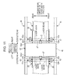
- the rolled paper sheet abnormal portion detecting sensors 52 and 52 are respectively provided on both end portions 42e1 and 42e2 of the carriage 42, as the example shown in Fig. 11 , even when an abnormal portion is not detected by the rolled paper sheet abnormal portion detecting sensor 52 on the right end portion 42e1 of the carriage 42 during the forward path (the fifth path, for example), the rolled paper sheet abnormal portion detecting sensor 52 on the left end portion 42e2 passes through the abnormal portion again before the head 31 passes through the abnormal portion. In other words, the head 31 passes through the abnormal portion during the forward path (the fifth path) described above, and immediately thereafter, the rolled paper sheet abnormal portion detecting sensor 52 on the left end portion 42e2 passes through the abnormal portion during the same forward path (the fifth path).
Landscapes
- Ink Jet (AREA)
- Handling Of Continuous Sheets Of Paper (AREA)
- Controlling Rewinding, Feeding, Winding, Or Abnormalities Of Webs (AREA)
- Handling Of Sheets (AREA)
Abstract
Description
- The present invention relates to a fluid ejecting apparatus.
- As an example of a fluid ejecting apparatus, an ink jet type printer has been known. This printer prints an image on a recording medium, such as a paper sheet, by causing a moving head to eject a fluid, such as ink, thereto. Furthermore, depending on the type of printer, when the printer performs a printing operation, foreign matter that adheres to various portions in the printer, such as a platen, is detected by an optical sensor or the like. Thereby, the foreign matter is prevented from interfering with the head before it happens (PTL 1).
- [PTL 1]
JP-A-2006-88612 - In such a printer, a label paper sheet (also called a seal paper sheet) may be used as the recording medium mentioned above. A label paper sheet has a recording paper sheet (recording material) in which the opposite side of a recording target surface for an image is an adhesive layer and a separator (peeling material) that is provided to cover the adhesive layer. Usually, the label paper sheet is provided to a user, in the shape of a rolled paper sheet that is wound into a roll. The label paper sheet is mounted on an unwinding portion of a user's printer, and an image is printed (recorded) on the recording paper sheet that is unwound and transported.
- When the label paper sheet is unwound, a peeling portion can be caused by partial peeling-off of the recording paper sheet from the separator. This peeling portion swells out because of a gap that is formed, due to the partial peeling-off described above, between the separator and the recording paper sheet. Thus, the peeling portion has an excessive thickness, compared to the original thickness of the label paper sheet. Therefore, there is a possibility that, during printing, the peeling portion may interfere with a head and damage the head.
- Thus, this printer is provided with an abnormal portion detecting sensor that detects, as an abnormal portion on a rolled paper sheet, not only the foreign matter adhering to the rolled paper sheet but also the peeling portion. As an example of the abnormal portion detecting sensor, a sensor having a configuration in which a light emitting portion and a light receiving portion are provided can be exemplified. In this case, the light emitting portion is disposed on one end side in a paper width direction of a rolled paper sheet. Also, the light receiving portion is disposed on the other end side in the paper width direction such that the light beam emitted from the light emitting portion is received on the other end. Furthermore, if an abnormal portion is a peeling portion, this sensor detects the generation of the peeling portion in the following manner. When the peeling portion moves relatively so as to pass through the abnormal portion detecting sensor, the light beam emitted from the light emitting portion is blocked by the peeling portion, and therefore the light receiving state of the light receiving portion is changed. Therefore, the generation of the peeling portion is detected based on the change in the light receiving state.
- A certain type of a print is configured to have a carriage and a pair of carriage guide rails. The carriage is adopted as a mechanism that causes a head to move to a predetermined position, relative to a recording medium on which fluid is ejected by the head. The carriage is supported by a carriage base and holds a head. The pair of carriage guide rails are disposed on both sides of the carriage so as to interpose the recording medium therebetween. The pair of carriage guide rails regulates a movement direction of the carriage base and movably supports the carriage base. Regarding the printer having such a configuration, it is difficult to maintain the processing accuracy of the carriage guide rail as an apparatus increases in size. In addition, the shape thereof is likely to be changed by bending, distortion or the like. Particularly, when a weight of the head and the carriage (including the carriage base) that supports the head increases owing to improvement in a drawing function, a large load is applied to the carriage guide rail. Thus, bending or distortion is likely to occur. Furthermore, when the carriage guide rail is bent or distorted, the state of the carriage base that is disposed in the vicinity of the area just above the carriage guide rail is changed due to the head (carriage) positioned on the carriage guide rail.
Thus, if the light emitting portion and the light receiving portion are fixed in the vicinity of the area just above the carriage guide rail, the positions of the light emitting portion and the light receiving portion are more likely to be displaced owing to the influence of the carriage guide rail. Therefore, the light beam emitted from the light emitting portion is not correctly received by the light receiving portion. As a result, there is a possibility that the abnormal portion on a recording medium may not be reliably detected. - The invention has been made to solve at least a part of the problem described above and can be realized as the following form or application example.
- [Application Example 1] A fluid ejecting apparatus according to an application example includes a transport portion that transports a recording medium, a support portion that supports the recording medium, a head that ejects a fluid onto the recording medium supported by the support portion, a carriage that holds the head and can move in a transport direction of the recording medium, a pair of carriage guide rails that supports the carriage such that the carriage can move in the transport direction of the recording medium, and an abnormal portion detecting sensor that has a light emitting portion which is disposed on one end side in a width direction of the recording medium, which is perpendicular to the transport direction of the recording medium, and a light receiving portion which is disposed on the other end side in the width direction such that a light beam emitted from the light emitting portion is received on the other end side, and detects an abnormal portion on the recording medium, in which the light emitting portion and the light receiving portion are mounted on the carriage via a sensor mounting member, and the sensor mounting member is fixed to the carriage at a position close to the center of the carriage in the width direction, within an area specified by the pair of carriage guide rails.
- According to the fluid ejecting apparatus, the sensor mounting member on which the light emitting portion and the light receiving portion are mounted is fixed to the carriage at a fixing position, which is close to the center of the area between the pair of carriage guide rails that are respectively disposed on both sides of the carriage so as to interpose the support portion therebetween. Therefore, even when the carriage guide rail is bent, it is difficult for the light emitting portion and the light receiving portion to be influenced. Thus, it is possible to maintain the positional relationship in which the light beam emitted from the light emitting portion is correctly received by the light receiving portion.
As a result, it is possible to improve the detection accuracy of the abnormal portion detecting sensor when detecting an abnormal portion, such as peeling of a recording medium that is supported on the support portion. - [Application Example 2] In the fluid ejecting apparatus according to the application example described above, it is preferable that the light emitting portion and the light receiving portion be aligned and mounted on the single sensor mounting member, and the sensor mounting member be fixed to the carriage at an intermediate position of an area between the light receiving portion and the light emitting portion.
- According to this configuration, the positional relationship between the light emitting portion and the light receiving portion is set such that the light emitting portion and the light receiving portion are subjected to less influence caused by the bending of the carriage guide rail. Thus, it is possible to detect an abnormal portion on a recording medium with high detection accuracy.
- [Application Example 3] In the fluid ejecting apparatus according to the application example described above, a pair of the abnormal portion detecting sensors may be provided so as to be aligned in the transport direction of the recording medium, and the pair of abnormal portion detecting sensors may be arranged so that the light emitting directions thereof are opposite to each other.
- According to the fluid ejecting apparatus, it is possible to effectively detect an abnormal portion even when the abnormal portion is partially generated at an arbitrary position in the paper width direction. In some cases, the abnormal portion is formed on a recording medium at a position close to one end or the other end in the paper width direction. However, when the pair of abnormal portion detecting sensors are arranged so that the light emitting directions thereof are opposite to each other, as described above, the pair of abnormal portion detecting sensors are symmetrically the same, in terms of detecting abilities, with respect to the center portion in the paper width direction. Thus, even when the abnormal portion is located on a paper sheet at a position close to one end or the other end on a paper sheet in the paper width direction, it is possible to detect the abnormal portion with high detection accuracy.
-
- [
Fig. 1] Fig. 1 is a schematic view showing a configuration of a printer. - [
Fig. 2] Fig. 2 is a block view showing a configuration of the printer. - [
Fig. 3] Figs. 3A and 3B are explanatory views of a curl restraining member.Fig. 3A shows a schematic top view of a platen, andFig. 3B shows a view taken along line B-B indicated by arrows inFig. 3A . - [
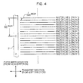
Fig. 4] Fig. 4 is an explanatory view of a printing operation and is a schematic view showing raster lines that are formed in respective paths when printing is carried out in eight paths. - [
Fig. 5] Fig. 5 is a schematic view that shows a movement of a head in a printing operation. - [
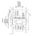
Fig. 6] Fig. 6 is an explanatory view of a rolled paper abnormal portion detecting sensor and is an enlarged plan view of a carriage in a state of moving in a printing area R. - [
Fig. 7] Fig. 7 is an explanatory view of the rolled paper abnormal portion detecting sensor and is a view taken along line B-B indicated by arrows inFig. 6 . - [
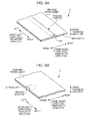
Fig. 8] Fig. 8A is a longitudinal cross-sectional view of a label paper sheet as a rolled paper sheet, andFig. 8B is a perspective view of the label paper sheet. - [
Fig. 9] Figs. 9A and 9B are perspective views of peeling portions that are examples of an abnormal portion on a rolled paper sheet. - [
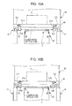
Fig. 10] Figs. 10A and 10B explain failure of a structure for mounting a rolled paper sheet abnormal portion detecting sensor, which differs from those of embodiments.Fig. 10A shows a front view of a carriage guide rail in a non-bent state, andFig. 10B shows a front view of the carriage guide rail in a bent state. - [
Fig. 11] Fig. 11 is a plan view showing a case where two pairs of rolled paper sheet abnormal portion detecting sensors are disposed on both right and left end portions of a carriage. - [
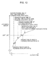
Fig. 12] Fig. 12 is a view that shows temporal variation of an expansion amount of an abnormal portion on a rolled paper sheet. - Hereinafter, embodiments of the invention will be described with reference to accompanying drawings. In addition, the size of each layer or each member in the drawings is different from its actual size to make each layer or each member have a recognizable size.
- A first embodiment of a
printer 1 as an example of a fluid ejecting apparatus will be described with reference toFigs. 1 and2 .Fig. 1 is a schematic cross-sectional view of theprinter 1, andFig. 2 is a block view of theprinter 1.
Furthermore, in the following description, an "up-down direction" and a "right-left direction" are directions shown by arrows inFig. 1 . Further, inFig. 1 , a "front-rear direction" is a direction perpendicular to a plane of paper. Additionally, the "front-rear direction" is parallel to a paper width direction of arolled paper sheet 2 as a printing object ofprinter 1. Thus, the front-rear direction is also referred to simply as the "paper width direction" in the following description. In addition, these up-down direction, right-left direction, and front-rear direction are perpendicular to one another. Moreover, a term "recording" that is used to describe "recording an image on the rolledpaper sheet 2" is also referred to simply as "printing" in the following description. - The
printer 1 causes the rolledpaper sheet 2, as a recording medium, (continuous paper sheet) to be unwound and transported along a predetermined transport path. Then, theprinter 1 causes an image to be printed on the rolledpaper sheet 2 in a printing area R that is set at a predetermined position on the transport path. Subsequently, the rolledpaper sheet 2 is rewound and treated as the image-printedrolled paper sheet 2.
As shown inFigs. 1 and2 , theprinter 1 has afeed unit 10, atransport unit 20, aplaten 29 as a support portion, a windingunit 90, ahead unit 30, acarriage unit 40, and ablower unit 80. Furthermore, theprinter 1 has acontroller 60 that manages an operation of theprinter 1 by controlling theseunits detector group 50. Hereinafter, details of these units and the like will be described. - The
feed unit 10 feeds the rolledpaper sheet 2 to thetransport unit 20. Thisfeed unit 10 has a windingshaft 18 that rotatably supports the rolledpaper sheet 2 in a wound state, and arelay roller 19 around which the rolledpaper sheet 2 unwound from the windingshaft 18 is wound and which introduces the rolledpaper sheet 2 into thetransport unit 20. Then, thefeed unit 10 feeds the rolledpaper sheet 2 to thetransport unit 20, corresponding to a transport operation of thetransport unit 20. - The
transport unit 20 transports the rolledpaper sheet 2 that is in an unwound state and sent from thefeed unit 10 from an upstream side to a downstream side, along a predetermined transport path. Thistransport unit 20 has a plurality ofrelay rollers first transport roller 23, a second transport roller 24, and a plurality ofrelay rollers Fig. 1 . Therelay rollers first transport roller 23 are disposed between thefeed unit 10 and theplaten 29. Meanwhile, the second transport roller 24 and the plurality ofrelay rollers platen 29 and the windingunit 90. Further, the rolledpaper sheet 2 is laid over theserollers paper sheet 2 is formed. Additionally, thistransport unit 20 is driven in cooperation with thefeed unit 10 described above, and thus functions as a "transport portion" according to claims. - Each of the first and second transport rollers 23 (24) is constituted of a pair of rollers. In both the first and second transport rollers 23 (24), one
roller 23a (24a) is constituted as a driving roller that is driven to rotate by a motor (not shown), and theother roller 23b (24b) is constituted as a driven roller that rotates in response to the rotation of the driving roller. Furthermore, when printing of an image is finished with respect to a part of the rolledpaper sheet 2 which is positioned in the printing area R, a part of the rolledpaper sheet 2 on which an image is printed is discharged from the printing area R by thefirst transport roller 23, the second transport roller 24, or the like. Subsequently, a new part of the rolledpaper sheet 2 on which an image is not printed yet is supplied to the printing area R and supplying the new part is stopped. Further, when transporting of the rolledpaper sheet 2 stops intermittently, an image is printed on the new part positioned in the printing area R. In other words, a printing operation with respect to the part of the rolledpaper sheet 2 which is positioned in the printing area R and a transport operation of the rolledpaper sheet 2 are repeatedly performed. This intermittent transport is carried out by thecontroller 60 by controlling rotation driving of thefirst transport roller 23 and the second transport roller 24.
Furthermore, in the transport path of the rolledpaper sheet 2, the printing area R described above is set so as to correspond to an upper surface of theplaten 29. In addition, a transport direction of the rolledpaper sheet 2 in the printing area R is parallel to the right-left direction. Thus, in the printing area R, the right-left direction can be referred to simply as the "transport direction" and may also be expressed as the "transport direction" in the following description. - The
head unit 30 prints an image on a part of the rolledpaper sheet 2 that is sent to the printing area R on the transport path by ejecting ink as an example of a fluid. Thehead unit 30 has ahead 31. Nozzle arrays that are constituted of a plurality of nozzles in a row are provided on a lower surface of thehead 31. In this example, the nozzle arrays that are each constituted of a plurality ofnozzles # 1 to #N are provided so as to respectively correspond to yellow (Y), magenta (M), cyan (C), black (K), and other colors. Eachnozzle group # 1 to #N constituting each nozzle array is linearly aligned in the paper width direction (front-rear direction). In addition, the nozzle arrays are arranged in parallel so as to be spaced apart from one another in the transport direction (right-left direction) of the rolledpaper sheet 2.
A piezoelectric element (not shown) as a driving element for ejecting ink is provided in each of thenozzles # 1 to #N. Furthermore, thecontroller 60 controls the application of voltage to both ends of the piezoelectric element. Thereby ink droplets are ejected from each of thenozzles # 1 to #N that corresponds to each color. - The
carriage unit 40 causes thehead 31 to move in the transport direction (right-left direction) and the paper width direction (front-rear direction) so as to print a two-dimensional image on the rolledpaper sheet 2. Thiscarriage unit 40 has acarriage guide rail 41 that extends in the transport direction (right-left direction), acarriage base 45 that is supported so as to reciprocatively move in the transport direction (right-left direction) along thecarriage guide rail 41, and acarriage 42 that is supported by thecarriage base 45. In addition, the carriage according to claims of this application includes thecarriage 42 and thecarriage base 45. - The
carriage 42 supported by thecarriage base 45 reciprocates, by the driving of a motor (not shown), in the transport direction (right-left direction) in a state of holding thehead 31 integrally. In addition, a head carriage guide rail (not shown) that extends in the paper width direction (front-rear direction) is provided in thecarriage 42. Thehead 31 is moved, along the head carriage guide rail, in the paper width direction (front-rear direction) by the driving of a motor (not shown). When the printing is carried out by thehead 31, thecarriage 42 that is supported by thecarriage base 45 moves reciprocatively in the transport direction using thecarriage guide rail 41 as a guide. When thecarriage 42 stops between a forward path and a returning path, thehead 31 is moved in the paper width direction by a predetermined distance d. By repeatedly performing these operation, a two-dimensional image is printed on a part of the rolledpaper sheet 2 in the printing area R. The printing operation will be described below. - A home position HP is prepared for the
carriage 42 that reciprocatively moves in the transport direction. The home position HP is a standby position at which the carriage 42 (head 31) stands by when the carriage 42 (head 31) does not perform the printing operation. During the transport operation where the rolledpaper sheet 2 is transported, thecarriage 42 is returned to the home position HP and stops, for example. The position of the home position HP is set to a position apart from theplaten 29 in the transport direction (right-left direction). In this example, the home position HP is set to a position which is further on the upstream side (that is, a left side in the right-left direction) than theplaten 29 in the transport direction. - The
platen 29 supports a part of the rolledpaper sheet 2 which is positioned in the printing area R. As described above, theplaten 29 is provided in the printing area R. That is, theplaten 29 is disposed between thefirst transport roller 23 and the second transport roller 24. In this example, the upper surface of theplaten 29 is a support surface for the rolledpaper sheet 2. In addition, the transport path of the rolledpaper sheet 2 in the printing area R is a line-shaped route in the right-left direction. Thus, the upper surface of theplaten 29 is formed in a planar shape in the right-left direction so as to correspond to the transport path. - A heater (not shown) is provided on the
platen 29 to heat a part of the rolledpaper sheet 2 which is positioned on the printing area R. The upper surface of theplaten 29 is heated by the heater, and therefore the ink that lands on a part of the rolledpaper sheet 2 which is on theplaten 29 is immediately dried. The heater is, for example, a nichrome wire that is embedded in theplaten 29. The heat quantity is controlled by applying electricity, and therefore the temperature of the rolledpaper sheet 2 on theplaten 29 is adjusted so as to be 45°C, for example. In addition, it may be configured that printing is performed at room temperature without providing a heater on theplaten 29. - Furthermore, to suppress the curl of the rolled
paper sheet 2 in the paper width direction and flatten the rolledpaper sheet 2, acurl restraining member 28 is disposed on the upper surface of theplaten 29.Figs. 3A and 3B are explanatory views of thecurl restraining member 28.Fig. 3A shows a schematic top view of theplaten 29, andFig. 3B shows a view taken along line B-B indicated by arrows inFig. 3A . Thecurl restraining member 28 is constituted of band-shapedplate members 28 that are provided so as to correspond torespective end portions paper sheet 2 in the paper width direction. Further, in each band-shapedplate member 28, anouter portion 28a in the paper width direction (front-rear direction) abuts on and is fixed to the upper surface of theplaten 29 and aninner portion 28b freely comes into contact with or separates from the upper surface of theplaten 29. Therefore, the curl of the rolledpaper sheet 2 is suppressed by inserting theend portion 2e of the rolledpaper sheet 2 between theinner portion 28b and the upper surface of theplaten 29. As a result, it is possible to suppress the interference of the rolledpaper sheet 2 with thehead 31 and stably print an image on the rolledpaper sheet 2. - The
blower unit 80 blows air toward the rolledpaper sheet 2 on theplaten 29. Thisblower unit 80 includes afan 81 and a motor (not shown) to rotate thefan 81. Thefan 81 is rotated and blows air to the rolledpaper sheet 2 on theplaten 29, and thereby the ink landed on the rolledpaper sheet 2 is dried. Blowing air also has the effect of maintaining a constant surrounding environment, for example maintaining a constant air temperature distribution around a platen. A plurality offans 81 described above are provided on a cover that is provided on a case of theprinter 1 so as to be openable and closable. In addition, when the cover is closed, eachfan 81 is positioned upward of theplaten 29 such that eachfan 81 is opposite to a part of the rolledpaper sheet 2 which abuts on and is supported by theplaten 29. - The winding
unit 90 winds a printed part of the rolledpaper sheet 2 that is sent by thetransport unit 20. The windingunit 90 has arelay roller 91 around which the rolledpaper sheet 2 sent from therelay roller 27 that is on the most downstream side of thetransport unit 20 is wound and a windingshaft 92 that winds the rolledpaper sheet 2 sent from therelay roller 91. The windingshaft 92 is driven to rotate by a motor (not shown) so as to correspond to the transport operation of thetransport unit 20. Thereby, the rolledpaper sheet 2 sent from thetransport unit 20 is quickly wound. - The
controller 60 is a control unit to control theprinter 1. Thiscontroller 60 has aninterface portion 61, aCPU 62, amemory 63, and aunit control circuit 64, as shown inFig. 2 . Theinterface portion 61 conducts transmission and reception of data between theprinter 1 and ahost computer 110 that is an external device. TheCPU 62 is a processing unit to control theentire printer 1. Thememory 63 ensures an area to store programs for theCPU 62 and a working area. TheCPU 62 controlsrespective units unit control circuit 64 that follows the program stored in thememory 63. - The
detector group 50 monitors the status of theprinter 1 and includes a rotary type encoder that is used to control the transport operation of the rolledpaper sheet 2 installed on the first andsecond transport rollers 23 and 24, for example, a paper sheet detecting sensor that detects the presence or absence of the rolledpaper sheet 2 to be transported, a linear type encoder that detects the position of the carriage 42 (or the head 31) in the transport direction (right-left direction), a rolled paper sheet abnormal portion detecting sensor 52 (seeFig. 6 ) that detects an abnormal portion on the rolledpaper sheet 2, such as foreign matter adhering to the rolledpaper sheet 2, and the like. In addition, the detection result from thedetector group 50 is transmitted to thecontroller 60. Thecontroller 60 controls, based on the detection result,respective units
Furthermore, details of a configuration of the rolled paper sheet abnormalportion detecting sensor 52 that is a principal portion in theprinter 1 of the invention will be described below. - As described above, the
printer 1 has thehead 31, and the nozzle array constituted of the nozzles aligned in the paper width direction (front-rear direction) is provided on thehead 31. In addition, thecontroller 60 causes thehead 31 to move in the transport direction (right-left direction) and eject ink from the nozzle, so that a raster line is formed along the transport direction (right-left direction). Thereby, an image is printed on a part of the rolledpaper sheet 2 which is positioned in the printing area R. Furthermore, to make it easy to explain, it is assumed that the number of the nozzle arrays on thehead 31 is one in the following description. However, as described above, the actual number of the nozzle arrays is plural so as to correspond to C, M, Y, K and other colors. - Subsequently, the
controller 60 executes printing with plural paths (six paths, eight paths, and 16 paths, for example). In other words, to increase the resolution of an image in the paper width direction (front-rear direction), printing is carried out so that the position of thehead 31 in the paper width direction for every other path is changed little by little. In addition, a well-known interlace (microwave) printing method is adopted as a method for printing. - Details of a printing operation will be described with reference to
Fig. 4. Fig. 4 is a schematic view showing raster lines that are formed in respective paths when printing is carried out with eight paths.
The nozzle array (nozzles) on thehead 31 is illustrated on the left side inFig. 4 . The head 31 (nozzle array) moves in the transport direction (right-left direction) and ejects ink from the nozzles, and therefore the raster line is formed. The position of the head 31 (nozzle array) in the paper width direction (front-rear direction), which is illustrated inFig. 4 , is a position in a first path. When the head 31 (nozzle array) maintains the position and moves in the transport direction, a first path printing is performed, and therefore three raster lines (raster lines L1, at the right end of whichpath 1 is written) shown inFig. 4 are formed. - Next, the head 31 (nozzle array) moves in the paper width direction, and the head 31 (nozzle array) maintains the position after the movement. Then, when the head 31 (nozzle array) moves in the transport direction, a second path printing is performed, and therefore two raster lines (raster lines L2, at the right end of which
path 2 is written) shown inFig. 4 are formed. Furthermore, a raster line L2 adjacent to a raster line L1 is formed by ink ejected from a nozzle that is different from a nozzle which ejects ink for forming the raster line L1, because an interlace (microwave) printing method is adopted. Thus, the moving distance of the head 31 (nozzle array) in the paper width direction is not set to 1/8 (1/180x1/8=1/1440 inch) of the distance between the nozzles (1/180 inch, for example) but set to a distance (hereinafter, the distance is represented by a distance d) greater than that. - Subsequently, third to eighth paths printing is performed by the operations which are similar to the operations described above, and therefore the other raster lines (raster lines L3 to L8, at the right ends of which
paths 3 to 8 are written, respectively) illustrated inFig. 4 is formed. In this way, the raster lines are formed in eight paths, and thus the resolution of an image in the paper width direction can be improved by as much as eight times (=1440÷180) what it was. - In the embodiment, a so-called bidirectional printing method is adopted. In other words, the movement direction of the head 31 (nozzle array) when the first path, the third path, the fifth path, or the seventh path printing is performed is opposite to the movement direction of the head 31 (nozzle array) when the second path, the fourth path, the sixth path, or the eighth path printing is performed.
-
Fig. 5 is an explanatory view of this bidirectional printing and is a schematic view showing the movement of thehead 31.
First, how to readFig. 5 will be explained.Fig. 5 shows how thehead 31 moves during the printing operation of the bidirectional printing. For convenience, thehead 31 is represented by a circle, and the movement of thehead 31 is represented by an arrow. Here, inFig. 5 , an arrow facing the right-left direction shows the movement of thehead 31 in the transport direction (that is, a first movement direction), and an arrow facing the up-down direction shows the movement of thehead 31 in the paper width direction (that is, a second movement direction). Furthermore, reference signs S1 to S18 are given to respective arrows. The reference sign is a step number which is used in the following description of the printing operation.
In addition, there are step numbers to whichpaths 1 to 8 are respectively assigned. These step numbers shows steps of ejecting ink, namely image printing steps. - Hereinafter, the printing operation of the bidirectional printing will be described with reference to
Figs. 4 and5 . Also, the printing operation is mainly executed by thecontroller 60. In the embodiment, specifically, the printing operation is performed by causing theCPU 62 to process a program stored in thememory 63. This program is constituted of codes to perform various operations described below. - When the rolled
paper sheet 2 stops due to the intermittent transport of the rolledpaper sheet 2 described above, the printing operation is to start to print an image on a part of the rolledpaper sheet 2 which is positioned in the printing area R. - First, the
controller 60 causes thehead 31 to move, from the home position HP, in a forward direction (a right direction in terms of the right-left direction, and a direction from the upstream side to the downstream side in terms of the transport direction) (step S1). Then, when thehead 31 enters the printing area R, thecontroller 60 executes the first path printing to cause thehead 31 to eject ink (step S2). By this operation, the raster line L1 (raster line of path 1) shown inFig. 4 is formed.
When thehead 31 arrives at a first turning position, thecontroller 60 causes thehead 31 to move forward in the paper width direction (step S3). In this example, thehead 31 moves forward by the distance d described above.
Then, thecontroller 60 causes thehead 31 to move in a returning direction (a left direction in terms of the right-left direction, and a direction from the downstream side to the upstream side in terms of the transport direction). At the same time, thecontroller 60 causes thehead 31 to eject ink. In this way, thecontroller 60 executes the second path printing (step S4). Therefore, the raster line L2 (raster line of path 2) shown inFig. 4 is formed.
Next, when thehead 31 arrives at a second turning position, thecontroller 60 causes thehead 31 to move forward in the paper width direction (step S5). In this example, thehead 31 moves forward by the distance d described above.
When the movement thereof is finished, thecontroller 60 executes two more times the same processes as steps S2 to S5 (steps S6 to S9 and steps S10 to S13). In a first process, the raster line L3 (a raster line of path 3) shown inFig. 4 is formed by the third path printing (step S6), and the raster line L4 (a raster line of path 4) shown inFig. 4 is formed by the fourth path printing (step S8). - Further, in a second process, the raster line L5 (a raster line of path 5) shown in
Fig. 4 is formed by the fifth path printing (step S10), and the raster line L6 (a raster line of path 6) shown inFig. 4 is formed by the sixth path printing (step S12). - Subsequently, the
controller 60 executes printing for the last two paths. In other words, thecontroller 60 causes thehead 31 to move in the forward direction and causes thehead 31 to eject ink. In this way, thecontroller 60 executes the seventh path printing (step S14). Therefore, the raster line L7 (raster line of path 7) shown inFig. 4 is formed. When thehead 31 arrives at the first turning position, thecontroller 60 causes thehead 31 to move forward in the paper width direction (step S15). In this example, thehead 31 moves forward by the distance d described above. Then, thecontroller 60 causes thehead 31 to move in the returning direction and causes thehead 31 to eject ink. In this way, thecontroller 60 executes the eighth path printing (step S16). Therefore, the raster line L8 (raster line of path 8) shown inFig. 4 is formed. - Next, when the
head 31 arrives at the second turning position, thecontroller 60 causes thehead 31 to return to the starting point in the paper width direction (step S17). In other words, thecontroller 60 causes thehead 31 to move, by the distance 7d, in a direction that is opposite the moving direction ofhead 31 in steps S3, S5, S7, S9, S11, S13, and S15, namely a backward direction in the paper width direction. - Then, the
controller 60 causes thehead 31 to move from the second turning position to the upstream side in the transport direction, such that thehead 31 returns to the home position HP (step S18). Therefore, the image printing operation is completed. - Incidentally, the reciprocation of the
head 31 in the transport direction (right-left direction) is carried out in the manner that thecarriage 42 reciprocates in the transport direction. In contrast, the movement of thehead 31 in the paper width direction (front-rear direction) is carried out in the manner that thehead 31 moves, relative to thecarriage 42, in the paper width direction. -
Figs. 6 and7 are explanatory views of the rolled paper sheet abnormalportion detecting sensor 52.Fig. 6 is an enlarged plan view of thecarriage 42 in a state of moving in the printing area R, andFig. 7 is a view taken along line B-B indicated by arrows inFig. 6 .
The principle that thehead 31 in the printing operation moves, over theplaten 29 in the printing area R, in the transport direction or the paper width direction is described above. However, in this case, the size of a gap G that is between the upper surface of theplaten 29 and the lower surface of thehead 31 is as narrow as the order of millimeters between about one mm and several mm, as shown inFig. 7 . Thus, if the foreign matter adheres to the rolledpaper sheet 2 to be printed and the rolledpaper sheet 2 swells up toward thehead 31 or if the rolledpaper sheet 2 is partially torn and rises toward thehead 31, the abnormal portion, such as the foreign matter or the torn portion, can come into contact with or interfere withhead 31 in a printing state. Therefore, thehead 31 can be damaged. - For this reason, the rolled paper sheet abnormal
portion detecting sensor 52 that detects an abnormal portion on the rolledpaper sheet 2 is mounted on theprinter 1. As shown inFigs. 6 and7 , this rolled paper sheet abnormalportion detecting sensor 52 is fixed to thecarriage base 45 via asensor mounting member 47. In other words, the rolled paper sheet abnormalportion detecting sensor 52 is integrally fixed to thecarriage 42 so as to be immovable relative to thecarriage 42. Therefore, the rolled paper sheet abnormalportion detecting sensor 52 that is integrated with thecarriage 42 reciprocates in the transport direction, namely the right-left direction. In other words, the rolled paper sheet abnormalportion detecting sensor 52 reciprocates in the transport direction, together with thecarriage 42. Normally, during the movement of thecarriage 42, namely over the entire period of the printing operation, the rolled paper sheet abnormalportion detecting sensor 52 enters an operation state by the control from thecontroller 60 and detects the abnormal portion on the rolledpaper sheet 2. - The rolled paper sheet abnormal
portion detecting sensor 52 is an optical sensor and constituted of alight emitting portion 52a that is disposed on one end side (front side in an example shown) in the paper width direction and alight receiving portion 52b that is arranged so that a laser beam, as an example of a light beam emitted from thelight emitting portion 52a, is received on the other end side (rear side in the example shown) in the paper width direction. Furthermore, a position of an optical axis of the laser beam in the up-down direction is adjusted to be positioned between the lower surface of thehead 31 and an upper surface of the rolled paper sheet 2 (that is, a surface facing thehead 31 or a surface not facing the platen 29). - Thus, in a case where an abnormal portion, such as the foreign matter, is present on the upper surface of the rolled
paper sheet 2 in a transport stop state, when the rolled paper sheet abnormalportion detecting sensor 52 that moves, together with thecarriage 42, in the transport direction (right-left direction) passes through the abnormal portion, a laser beam emitted from thelight emitting portion 52a is blocked by the abnormal portion. As a result, the light receiving state of thelight receiving portion 52b is changed. In other words, an amount of light received by thelight receiving portion 52b is reduced. Thus, the presence or absence of an abnormal portion is detected by monitoring the light receiving amount. For example, an amount of light received is converted into an electrical signal, such as voltage or current, by anadequate converter 52c embedded in the rolled paper sheet abnormalportion detecting sensor 52, and the electrical signal is almost continuously transmitted to thecontroller 60. When the electrical signal is below a predetermined threshold value which is, for example, an electrical signal value set in advance, thecontroller 60 determines that "an abnormal portion is present". In this case, thecontroller 60 causes thecarriage 42 to stop, and then causes thecarriage 42 to return to the home position HP. In this way, the abnormal portion is prevented from coming into contact with or interfering with thehead 31, before it happens. - Incidentally, when the rolled
paper sheet 2 is transported into the printing area R, thecarriage 42 stands by at the home position HP shown inFig. 1 (orFig. 6 ). The home position HP is positioned outside the printing area R. Thus, even when a part of the rolledpaper sheet 2 having an abnormal portion is transported into the printing area R, the abnormal portion does not interfere with thehead 31 in thecarriage 42 during the transport. - The rolled paper sheet abnormal
portion detecting sensor 52 is provided on at least one of two end portions 42e1 and 42e2 of thecarriage 42 in the transport direction (right-left direction). In a case where the rolled paper sheet abnormalportion detecting sensor 52 is provided on only one end portion, as an example shown inFig. 6 , the rolled paper sheet abnormalportion detecting sensor 52 is installed on the end portion 42e1 that can arrive at an abnormal portion before thehead 31 arrives thereat during the first path printing operation, namely the first movement of thecarriage 42 in the right-left direction. In the example shown inFig. 6 , for example, the right end portion 42e1 (end portion 42e1 on the downstream side, in terms of the transport direction) of thecarriage 42 can arrive at a part of the rolledpaper sheet 2 which is on theplaten 29 before thehead 31 arrives thereat, because the home position HP is positioned further left than theplaten 29 in the right-left direction (further on the upstream side than theplaten 29, in terms of the transport direction). Thus, the rolled paper sheet abnormalportion detecting sensor 52 is installed on the right end portion 42e1 of the carriage 42 (end portion 42e1 on the downstream side, in terms of the transport direction). - Hereinafter, details of a method for fixing the rolled paper sheet abnormal
portion detecting sensor 52, which is the most important configuration of theprinter 1 according to the invention, will be described.
As shown inFigs. 6 and7 , thelight emitting portion 52a and thelight receiving portion 52b that constitute the rolled paper sheet abnormalportion detecting sensor 52 are fixed to thecarriage base 45 via thesensor mounting member 47. In the embodiment, thelight emitting portion 52a and thelight receiving portion 52b are mounted, spaced apart from each other at a predetermined interval, on a singlesensor mounting member 47. Thesensor mounting member 47 on which thelight emitting portion 52a and thelight receiving portion 52b are mounted is fixed to thecarriage base 45 at a fixing position G, which is close to the center of the area between the pair ofcarriage guide rails 41 that are respectively disposed on both sides of thecarriage base 45 so as to interpose theplaten 29 therebetween. Therefore, it is possible for the rolled paper sheet abnormalportion detecting sensor 52 to have a configuration in which the laser beam emitted from thelight emitting portion 52a is certain to be received by thelight receiving portion 52b, and therefore an abnormal portion on the rolledpaper sheet 2 can be reliably detected. Hereinafter, it will be described how an abnormal portion is reliably detected. - Failure that can be caused when the fixing position of the
light emitting portion 52a and thelight receiving portion 52b of the rolled paper sheet abnormalportion detecting sensor 52 are not accurately specified, as in this embodiment, will be described with reference to the drawings.Fig. 10 explains failure of a structure for mounting the rolled paper sheet abnormalportion detecting sensor 52, which differs from those of the embodiments.Fig. 10A shows a front view of acarriage guide rail 41 in a non-bent state, andFig. 10B shows a front view of a carriage guide rail in a bent state.
In a structure for mounting a rolled paper sheet abnormal portion detecting sensor 52' shown inFig. 10 , alight emitting portion 52a' is mounted on thecarriage base 45 via a sensor mounting member 47a', and alight receiving portion 52b' is mounted on thecarriage base 45 via a sensor mounting member 47b'. In this structure, respective sensor mounting members 47a' and 47b' are fixed to thecarriage base 45 at fixing positions G'1 and G'2, which are in the vicinity of the area just above thecarriage guide rail 41. In a case where thelight emitting portion 52a' and thelight receiving portion 52b' are fixed at these fixing positions G'1 and G'2, there is a high possibility that the positions of thelight emitting portion 52a' and thelight receiving portion 52b' are displaced by the influence of thecarriage guide rail 41. It is difficult to maintain the processing accuracy of thecarriage guide rail 41 as an apparatus increases in size. In addition, the shape thereof is likely to be changed by bending, distortion, or the like. Particularly, when a weight of thehead 31 and the carriage 42 (including the carriage base 45) that supports thehead 31 increases owing to improvement in a drawing function, thecarriage guide rail 41 is likely to be bent or distorted. Furthermore, when the carriage guide rail is bent or distorted, the state of thecarriage base 45 that is disposed in the vicinity of the area just above thecarriage guide rail 41 is changed due to the head 31 (carriage 42) positioned on thecarriage guide rail 41. Even in a case where the optical axis is adjusted such that, in a non-bent state of thecarriage guide rail 41, a laser beam emitted from thelight emitting portion 52a' of the rolled paper sheet abnormalportion detecting sensor 52 can be received by thelight receiving portion 52b', as shown inFig. 10A , for example, if thecarriage guide rail 41 is bent, as shown inFig. 10B , thelight emitting portion 52a' and thelight receiving portion 52b' that are each fixed at the fixing position G'1 and G'2, via the sensor mounting members 47a' and 47b', which are in the vicinity of the area just above thecarriage guide rail 41, are displaced. Therefore, the laser beam emitted from thelight emitting portion 52a' cannot be correctly received by thelight receiving portion 52b' and this results in the failure that an abnormality of the rolledpaper sheet 2 on theplaten 29 cannot be detected accurately. - In contrast, the structure for mounting the rolled paper sheet abnormal
portion detecting sensor 52 of the embodiment, which is shown inFigs. 6 and7 , are configured so that thesensor mounting member 47 on which thelight emitting portion 52a and thelight receiving portion 52b are mounted is fixed to thecarriage base 45 at the fixing position G, which is close to the center of the area between the pair ofcarriage guide rails 41 that are respectively disposed on both sides of thecarriage 42 so as to interpose theplaten 29 therebetween. Therefore, even when thecarriage guide rail 41 is bent, thelight emitting portion 52a and thelight receiving portion 52b are hardly influenced. Thus it is possible for the rolled paper sheet abnormalportion detecting sensor 52 to detect an abnormality on the rolledpaper sheet 2 supported on theplaten 29 with high accuracy.
Furthermore, in the embodiment, the supporting structure for the rolled paper sheet abnormalportion detecting sensor 52 is configured so that thelight emitting portion 52a and thelight receiving portion 52b are mounted, spaced apart from each other at the predetermined interval, on the integratedsensor mounting member 47 and a section of thesensor mounting member 47 which is close to the center of the area between thelight emitting portion 52a and thelight receiving portion 52b is fixed to thecarriage base 45 at the fixing position G which is close to the center of the area between the pair of carriage guide rails 41. Thus, the positional relationship between thelight emitting portion 52a and thelight receiving portion 52b is set such that thelight emitting portion 52a and thelight receiving portion 52b are subjected to less influence caused by the bending of thecarriage guide rail 41. As a result, it is possible to detect an abnormal portion on the rolledpaper sheet 2 with high detection accuracy. - Next, details of the rolled paper sheet abnormal
portion detecting sensor 52 will be described to place a focus on an operation for detecting an abnormal portion on the rolledpaper sheet 2 as a recording medium.
In the embodiment, a label paper sheet is used as the rolled paper sheet (recording medium) 2.Fig. 8A is a longitudinal cross-sectional view of a label paper sheet, andFig. 8B is a perspective view of the label paper sheet. The label paper sheet is also commonly referred to as a seal paper sheet. That is, a label paper sheet has a printing paper sheet (corresponding to recording material) in which the opposite side of a printing target surface for an image is an adhesive layer and a separator (peeling material) that is provided to cover the adhesive layer. In addition, it is easy to separate the separator from the printing paper sheet. When using the printed rolledpaper sheet 2, an end user peels off the separator from the printing paper sheet and attaches it to a desired object. The printing paper sheet and the separator are not limited to being formed from any kind of paper, and may be formed from a resin film or the like.
When the rolledpaper sheet 2, such as a label paper sheet, is set to theprinter 1, the rolledpaper sheet 2 is set in the printing area R such that the printing paper sheet side faces thehead 31 and the separator side faces theplaten 29. - When the rolled
paper sheet 2, such as a label paper sheet, is unwound, a peeling portion can be caused by partial peeling-off of the recording paper sheet from a separator.Figs. 9A and 9B are perspective views of a general example of peeling portions. As shown inFigs. 9A and 9B , the peeling portion swells up, in a paper thickness direction, by a gap that is formed, due to the partial peeling-off described above, between the separator and the printing paper sheet. In many cases, the peeling portion has a linear shape parallel to the right-left direction, namely the transport direction, as shown inFig. 9A or the peeling portion is formed in either end portion of the rolledpaper sheet 2 in the front-rear direction, namely the paper width direction, as shown inFig. 9B . In other cases, the peeling portion that is in the direction shown inFig. 9B may be formed linearly so as to be parallel to the front-rear direction, namely the paper width direction of the rolled paper sheet 2 (that is, the peeling portion is linearly formed so as to cross both one end portion and the other end portion in the front-rear direction, namely the paper width direction). - Regardless of what shape the peeling portion is formed in, the peeling portion has an excessive thickness, up to as thick as the swelling portion, compared to the original thickness of the label paper sheet. Therefore, there is a possibility that, during printing, the peeling portion may come into contact with or interfere with the
head 31 and damage thehead 31. For this reason, the rolled paper sheet abnormalportion detecting sensor 52 described above also detects this peeling portion as an abnormal portion on the rolledpaper sheet 2. That is, the peeling portion that is formed as shown inFig. 9A or Fig. 9B can be detected as follows. When the rolled paper sheet abnormalportion detecting sensor 52 moves in the right-left direction, namely the transport direction, and passes through the peeling position, the light beam emitted is reliably blocked for a certain period, and therefore an amount of light received is greatly reduced. Therefore, it is possible to detect the peeling portion. -
Fig. 11 is an explanatory view that shows a preferable arrangement example of the rolled paper sheet abnormalportion detecting sensor 52 and is a plan view showing a case where two pairs of the rolled paper sheet abnormalportion detecting sensors carriage 42. The same reference sign is given to a configuration same as that of the embodiment described above, and the description thereof will not be repeated. - In this arrangement example, two rolled paper sheet abnormal
portion detecting sensors carriage 42 so as to be adjacently aligned on the right and the left sides in the transport direction, as shown inFig. 11 . A pair of these rolled paper sheet abnormalportion detecting sensors
First, regarding one end portion 42e1 of both of the right and the left end portions 42e1 and 42e2 of thecarriage 42, an effect of the configuration in which two rolled paper sheet abnormalportion detecting sensors Fig. 9B results in an abnormal portion, the abnormal portion may be formed at a position close to the rear side or the front side of the paper sheet in the paper width direction (in theFig. 9 , the peeling portion is formed at a position close to the front side in the paper width direction). However, it is possible to effectively detect the abnormal portion in either case. Hereinafter, it will be described how the abnormal portion is effectively detected in either case. - Regarding the rolled paper sheet abnormal
portion detecting sensor 52, there is a possibility that the detection accuracy at either one of a position close to thelight emitting portion 52a or a position to thelight receiving portion 52b in the paper width direction is higher (or lower) than that at the other one. It can be conceived that the reason is as follows. Theplaten 29 is heated to about 45°C to dry ink landed on the rolledpaper sheet 2, as described above. Thus, there is air temperature distribution in an area over theplaten 29 and the rolledpaper sheet 2. The temperature of the area surrounding theplaten 29 is as high as 45°C, for example, and the temperature is lowered to about 25°C going upward from theplaten 29. Therefore, a refractive index of light is changed in the area due to the air temperature distribution. As a result, the laser beam emitted from thelight emitting portion 52a is refracted upward. In this case, if an abnormal portion is present at the position close to thelight receiving portion 52b in the paper width direction, the abnormal portion cannot adequately block the laser beam. As a result, there is a possibility that the rolled paper sheet abnormalportion detecting sensor 52 may not detect the abnormal portion because an amount of light received is reduced a little. - For this reason, in the example shown in
Fig. 11 , the pair of rolled paper sheet abnormalportion detecting sensors portion detecting sensors light receiving portion 52b of one rolled paper sheet abnormalportion detecting sensor 52 and where the detection accuracy of the rolled paper sheet abnormalportion detecting sensor 52 is decreased can be covered by the area which is close to thelight emitting portion 52a of the other rolled paper sheet abnormalportion detecting sensor 52 and where the detection accuracy of the rolled paper sheet abnormalportion detecting sensor 52 is increased. Similarly, the area which is close to thelight receiving portion 52b of the other rolled paper sheet abnormalportion detecting sensor 52 and where the detection accuracy of the rolled paper sheet abnormalportion detecting sensor 52 is decreased can be covered by the area which is close to thelight emitting portion 52a of one rolled paper sheet abnormalportion detecting sensor 52 and where the detection accuracy of the rolled paper sheet abnormalportion detecting sensor 52 is increased. - Specifically, in one rolled paper sheet abnormal
portion detecting sensor 52, thelight emitting portion 52a thereof is installed on the front side in the paper width direction and thelight receiving portion 52b thereof is installed on the rear side in the same direction. Furthermore, in the other rolled paper sheet abnormalportion detecting sensor 52, thelight emitting portion 52a thereof is installed on the rear side in the paper width direction and thelight receiving portion 52b thereof is installed on the front side in the same direction. Therefore, if the configuration in which the front range in the paper width direction is detected by the preceding rolled paper sheet abnormalportion detecting sensor 52 and the rear range in the paper width direction is detected by the following rolled paper sheet abnormalportion detecting sensor 52 is adopted, it is possible to reliably detect an abnormal portion at an arbitrary position in the paper width direction, without being influenced by the refraction of the laser beam described above. Incidentally, to ensure this operation, thecontroller 60 adopts control flow in which, if at least one electrical signal from two rolled paper sheet abnormalportion detecting sensors - It is preferable that such a pair of rolled paper sheet abnormal
portion detecting sensors 52 and 52 (seeFig. 11 ) or a rolled paper sheet abnormal portion detecting sensor 52 (seeFig. 6 ) is provided not only on one end portion of thecarriage 42 in the right-left direction (the transport direction) but on both end portions thereof. In the example shown inFig. 11 , a pair of rolled paper sheet abnormalportion detecting sensors carriage 42.
According to this configuration, even in a case where an abnormal portion on the rolledpaper sheet 2 gradually grows and rises toward thehead 31 in a printing state, it is easy to detect the abnormal portion before the abnormal portion comes into contact withhead 31.
As an example of the growing abnormal portion, there is a case where a printing paper sheet partially expands due to a fluid which is contained in ink landed, during the printing, on the rolledpaper sheet 2.Fig. 12 is a view showing a graph that shows temporal variation of an expansion amount of the abnormal portion. In the graph, the vertical axis represents the expansion amount and the horizontal axis represents elapsed time from a start time of a printing operation. Furthermore, a limit line shown in the graph represents the boundary value of the expansion amount where an abnormal portion interferes with thehead 31. - In a case where the rolled paper sheet abnormal
portion detecting sensor 52 is provided only on the right end portion 42e1 of thecarriage 42, as described above (seeFig. 6 ), when the forward path (the fifth path, for example) of thecarriage 42 is carried out as described above, there is no chance of detecting an abnormal portion before the subsequent returning path (the sixth path) thereof is carried out. Furthermore, in the returning path (the sixth path), thehead 31 passes through an abnormal portion, and then the rolled paper sheet abnormalportion detecting sensor 52 passes through the abnormal portion. Thus, in some cases, an abnormal portion in which the expansion amount exceeds a limit value may interfere with thehead 31 during the returning path (the sixth path), as shown inFig. 12 . - On the other hand, if the rolled paper sheet abnormal
portion detecting sensors carriage 42, as the example shown inFig. 11 , even when an abnormal portion is not detected by the rolled paper sheet abnormalportion detecting sensor 52 on the right end portion 42e1 of thecarriage 42 during the forward path (the fifth path, for example), the rolled paper sheet abnormalportion detecting sensor 52 on the left end portion 42e2 passes through the abnormal portion again before thehead 31 passes through the abnormal portion. In other words, thehead 31 passes through the abnormal portion during the forward path (the fifth path) described above, and immediately thereafter, the rolled paper sheet abnormalportion detecting sensor 52 on the left end portion 42e2 passes through the abnormal portion during the same forward path (the fifth path). In addition, during the subsequent returning path (the sixth path), the rolled paper sheet abnormalportion detecting sensor 52 on the same left end portion 42e2 passes through the abnormal portion before thehead 31 passes through the abnormal portion. Therefore, the rolled paper sheet abnormalportion detecting sensor 52 on the left end portion 42e2 has twice the chance of detection, and thus the expansion amount which varies with the elapsed time can be monitored more successively and accurately. As a result, it is possible to more certainly prevent the growing abnormal portion from interfering with thehead 31. In addition, although the above description focuses on a case where the forward path precedes the returning path, it is needless to say that the same operation can be carried out in a case where the returning path precedes the forward path. - Hereinbefore, the embodiments of the invention that is proposed by the inventor are described in detail. However, the invention is not intended to be limited to the embodiments described above, and it is possible to make various modifications as long as they do not depart from the spirit and scope thereof.
The fluid ejecting apparatus is mainly described in the embodiments described above, but description of a fluid ejecting method or the like is also included, for example. Furthermore, the embodiments described above are intended to facilitate the understanding of the invention, and are not intended to be construed as limiting the invention. It is needless to say that the invention can be modified or improved, as long as it does not depart from the spirit and scope thereof, and includes equivalents thereof. Particularly, the invention also includes embodiments described below. - In the embodiments described above, a fluid ejecting apparatus is embodied in a ink jet type printer. However, a fluid ejecting apparatus that ejects or discharges a fluid aside from ink may also be available, and furthermore, various types of fluid ejecting apparatuses that are equipped with a fluid ejecting head or the like ejecting a small amount of a liquid droplets can be adopted. In addition, a liquid droplet means the state of the fluid which is ejected from the fluid ejecting apparatus, and includes granule forms, teardrop forms, and forms that pull trails in a string-like form therebehind. In addition, the fluid referred to here can be any material capable of being ejected or discharged by the fluid ejecting apparatus. For example, any matter can be used as long as the matter is in its fluid phase, including fluids having high or low viscosity, sol, gel water, other inorganic solvents, organic solvents, fluid solutions, fluid resins, and fluid states such as fluid metals (metallic melts). Furthermore, in addition to fluids as a single state of matter, fluids in which particles of a functional material composed of a solid matter such as pigments, metal particles, or the like are dissolved, dispersed, or mixed in a fluid carrier are included as well. Ink, a fluid crystal, or the like is exemplified as a representative example of a fluid in the embodiments described above. In this case, the ink includes a general water-based ink and oil-based ink, aside from various fluid compositions of a gel ink, a hot melt ink, or the like.
- Furthermore, in the embodiments described above, the
light emitting portion 52a and thelight receiving portion 52b of the rolled paper sheet abnormalportion detecting sensor 52 are mounted on a singlesensor mounting member 47 and thesensor mounting member 47 is fixed to thecarriage base 45 at the fixing position G. However, without being limited thereto, thelight emitting portion 52a and thelight receiving portion 52b may be fixed to thecarriage base 45 via sensor mounting members that are separately provided. In this case, by setting a position which is close to the center of the area between the pair ofcarriage guide rails 41 as a fixing position of respective sensor mounting members to thecarriage base 45, it is possible to suppress the influence caused by bending or distortion of thecarriage guide rail 41, by the same effect as that in the embodiment described above. Therefore, it is possible to ensure the detection accuracy of the rolled paper sheet abnormalportion detecting sensor 52 when detecting an abnormal portion on a recording medium (rolled paper sheet 2). - In addition, an example where the direction of the optical axis which links the
light emitting portion 52a and thelight receiving portion 52b of the rolled paper sheet abnormalportion detecting sensor 52 is set to be parallel to the front-rear direction, namely the paper width direction of the rolledpaper sheet 2, is explained in the embodiments described above.
However, without being limited thereto, the direction of the optical axis which links thelight emitting portion 52a and thelight receiving portion 52b of the rolled paper sheet abnormalportion detecting sensor 52 may be inclined, at a predetermined angle, in the front-rear direction, namely the paper width direction of the rolledpaper sheet 2. In this case, if, for example, a peeling portion is formed linearly so as to be parallel to the front-rear direction, namely the paper width direction of the rolledpaper sheet 2, as a peeling portion extending in a direction shown inFig. 9B , (that is, the peeling portion is linearly formed so as to cross both one end portion and the other end portion in the front-rear direction, namely the paper width direction), it is possible to prevent detection failure where the laser beam emitted from thelight emitting portion 52a passes through a tunnel-shaped gap of the peeling portion and arrives at thelight receiving portion 52b, and therefore, the peeling portion is not detected. Thus, it is possible to maintain high detection accuracy when detecting an abnormal portion on the rolledpaper sheet 2, such as a peeling portion. - Furthermore, in the embodiments described above, the printer (liquid droplet ejecting device) forms an image on a recording medium on the platen by causing the head carriage including the ink jet head to scan the recording medium that is positioned on the platen, and causing the ink jet head to eject ink during the scanning. However, the configuration of the printer is not limited thereto, and the operation and effect of the invention can be achieved as long as the printer is configured so that the ink jet head moves relative to the recording medium and ink is ejected from the ink jet head during the relative movement. The printer may be a so-called line head type ink jet printer in which an ink jet head is fixed inside a printing device and only a recording medium moves in the transport direction so as to receive ink which is ejected from the ink jet head.
- 1: printer as fluid ejecting apparatus, 2: rolled paper sheet as recording medium, 10: feed unit, 20: transport unit, 29: platen as support portion, 30: head unit, 31: head, 40: carriage unit, 41: carriage guide rail, 42: carriage, 45: carriage base, 47: sensor mounting member, 50: detector group, 52: abnormal portion detecting sensor, 52a: light emitting portion, 52b: light receiving portion, 52c: converter, 60: controller, 61: interface portion, 62: CPU, 63: memory, 64: unit control circuit, 80: blower unit, 81: fan, 90: winding unit, 110: host computer
- While this invention has been described in conjunction with the specific embodiments thereof, it is evident that many alternatives, modifications, and variations will be apparent to those skilled in the art. Accordingly, preferred embodiments of the invention as set forth herein are intended to be illustrative, not limiting. There are changes that may be made without departing from the spirit and scope of the invention. The entire disclosure of Japanese Patent Application No.
2012-188407, filed on August 29, 2012
Claims (3)
- A fluid ejecting apparatus comprising:a transport portion that transports a recording medium;a support portion that supports the recording medium;a head that ejects a fluid onto the recording medium supported by the support portion;a carriage that holds the head and can move in a transport direction of the recording medium;a pair of carriage guide rails that supports the carriage such that the carriage can move in the transport direction of the recording medium; andan abnormal portion detecting sensor that has a light emitting portion which is disposed on one end side in a width direction of the recording medium, which is perpendicular to the transport direction of the recording medium, and a light receiving portion which is disposed on the other end side in the width direction such that a light beam emitted from the light emitting portion is received on the other end side, and detects an abnormal portion on the recording medium,wherein the light emitting portion and the light receiving portion are mounted on the carriage via a sensor mounting member, andwherein the sensor mounting member is fixed to the carriage at a position close to the center of the carriage in the width direction, within an area specified by the pair of carriage guide rails.
- The fluid ejecting apparatus according to Claim 1,
wherein the light emitting portion and the light receiving portion are aligned and mounted on the single sensor mounting member, and
wherein the sensor mounting member is fixed to the carriage at an intermediate position in an area between the light receiving portion and the light emitting portion. - The fluid ejecting apparatus according to Claim 1,
wherein a pair of the abnormal portion detecting sensors are provided so as to be aligned in the transport direction of the recording medium, and
wherein the pair of abnormal portion detecting sensors are arranged so that the light emitting directions thereof are opposite to each other.
Priority Applications (1)
| Application Number | Priority Date | Filing Date | Title |
|---|---|---|---|
| EP13182836.0A EP2703172B1 (en) | 2012-08-29 | 2013-09-03 | Fluid ejecting apparatus |
Applications Claiming Priority (2)
| Application Number | Priority Date | Filing Date | Title |
|---|---|---|---|
| JP2012188407A JP5935600B2 (en) | 2012-08-29 | 2012-08-29 | Liquid ejection device |
| EP13182836.0A EP2703172B1 (en) | 2012-08-29 | 2013-09-03 | Fluid ejecting apparatus |
Publications (3)
| Publication Number | Publication Date |
|---|---|
| EP2703172A2 true EP2703172A2 (en) | 2014-03-05 |
| EP2703172A3 EP2703172A3 (en) | 2014-11-05 |
| EP2703172B1 EP2703172B1 (en) | 2015-12-02 |
Family
ID=49513712
Family Applications (1)
| Application Number | Title | Priority Date | Filing Date |
|---|---|---|---|
| EP13182836.0A Not-in-force EP2703172B1 (en) | 2012-08-29 | 2013-09-03 | Fluid ejecting apparatus |
Country Status (3)
| Country | Link |
|---|---|
| US (1) | US9022516B2 (en) |
| EP (1) | EP2703172B1 (en) |
| JP (1) | JP5935600B2 (en) |
Cited By (1)
| Publication number | Priority date | Publication date | Assignee | Title |
|---|---|---|---|---|
| EP3141393A1 (en) * | 2015-09-03 | 2017-03-15 | FUJIFILM Corporation | Inkjet recording apparatus |
Families Citing this family (2)
| Publication number | Priority date | Publication date | Assignee | Title |
|---|---|---|---|---|
| JP2024034124A (en) * | 2022-08-31 | 2024-03-13 | セイコーエプソン株式会社 | printing device |
| JP2025029700A (en) * | 2023-08-22 | 2025-03-07 | セイコーエプソン株式会社 | Printing device |
Citations (1)
| Publication number | Priority date | Publication date | Assignee | Title |
|---|---|---|---|---|
| JP2006088612A (en) | 2004-09-27 | 2006-04-06 | Seiko Epson Corp | Printer and foreign object detection method |
Family Cites Families (13)
| Publication number | Priority date | Publication date | Assignee | Title |
|---|---|---|---|---|
| US3490674A (en) * | 1968-03-25 | 1970-01-20 | Rockford Servo Corp | Web alignment apparatus |
| US3600591A (en) * | 1970-01-13 | 1971-08-17 | Feldmuehle Ag | Apparatus for detecting surface elevations on a moving sheet |
| JP3088578B2 (en) * | 1992-02-26 | 2000-09-18 | キヤノン株式会社 | INK JET RECORDING APPARATUS AND METHOD OF MANUFACTURING INK JET RECORDINGS |
| US5541626A (en) * | 1992-02-26 | 1996-07-30 | Canon Kabushiki Kaisha | Recording apparatus and method for manufacturing recorded product thereby |
| JPH11291476A (en) * | 1998-04-03 | 1999-10-26 | Copyer Co Ltd | Ink jet imaging apparatus |
| JP2003291478A (en) * | 2002-04-04 | 2003-10-14 | Seiko Instruments Inc | Print head serial printer |
| JP4258258B2 (en) * | 2002-04-16 | 2009-04-30 | セイコーエプソン株式会社 | Ink cartridge detection mechanism, ink jet printer, and ink cartridge |
| EP1676707B1 (en) * | 2002-04-16 | 2008-09-17 | Seiko Epson Corporation | Ink cartridge |
| JP4089277B2 (en) | 2002-04-23 | 2008-05-28 | ブラザー工業株式会社 | Printhead interference detection device for ink jet printer |
| WO2006128849A2 (en) * | 2005-05-30 | 2006-12-07 | Agfa Graphics Nv | Collision avoidance method and sensor |
| JP4670558B2 (en) * | 2005-09-13 | 2011-04-13 | 富士ゼロックス株式会社 | Droplet discharge device |
| JP5982969B2 (en) * | 2012-04-09 | 2016-08-31 | セイコーエプソン株式会社 | Liquid ejection apparatus and liquid ejection method |
| JP2015037982A (en) * | 2012-08-24 | 2015-02-26 | 株式会社Pfu | Document feeder, jam determination method, and computer program |
-
2012
- 2012-08-29 JP JP2012188407A patent/JP5935600B2/en not_active Expired - Fee Related
-
2013
- 2013-09-03 US US14/016,647 patent/US9022516B2/en not_active Expired - Fee Related
- 2013-09-03 EP EP13182836.0A patent/EP2703172B1/en not_active Not-in-force
Patent Citations (1)
| Publication number | Priority date | Publication date | Assignee | Title |
|---|---|---|---|---|
| JP2006088612A (en) | 2004-09-27 | 2006-04-06 | Seiko Epson Corp | Printer and foreign object detection method |
Cited By (1)
| Publication number | Priority date | Publication date | Assignee | Title |
|---|---|---|---|---|
| EP3141393A1 (en) * | 2015-09-03 | 2017-03-15 | FUJIFILM Corporation | Inkjet recording apparatus |
Also Published As
| Publication number | Publication date |
|---|---|
| JP5935600B2 (en) | 2016-06-15 |
| US20140078201A1 (en) | 2014-03-20 |
| EP2703172A3 (en) | 2014-11-05 |
| EP2703172B1 (en) | 2015-12-02 |
| JP2014046460A (en) | 2014-03-17 |
| US9022516B2 (en) | 2015-05-05 |
Similar Documents
| Publication | Publication Date | Title |
|---|---|---|
| US9676202B2 (en) | System and method for detecting defects in an inkjet printer | |
| EP3257674B1 (en) | Image recording device, and image recording method | |
| US9114652B1 (en) | System for detecting inoperative inkjets in printheads ejecting clear ink using heated thermal substrates | |
| US9022522B2 (en) | Liquid ejecting apparatus and method for detecting foreign matter | |
| US9033454B2 (en) | Liquid discharge device and liquid discharge method | |
| JP5861308B2 (en) | Liquid ejection device | |
| JP6122124B2 (en) | Printing system services | |
| US8985725B2 (en) | Method and apparatus for alignment of a low contrast ink printhead in an inkjet printer | |
| US9682573B2 (en) | Printer having edge control apparatus for web media | |
| US9248667B2 (en) | Method to operate an inkjet printer with at least two printing stations, and inkjet printer with two printing stations | |
| US8376516B2 (en) | System and method for operating a web printing system to compensate for dimensional changes in the web | |
| CN104070837B (en) | Wrinkle Detection In Continuous Feed Printers | |
| EP2414163B1 (en) | Depositing drops on a substrate carried by a stage | |
| EP2703172B1 (en) | Fluid ejecting apparatus | |
| CN104553327B (en) | Liquid liquid discharging device | |
| US8764151B2 (en) | System and method for preserving edges while enabling inkjet correction within an interior of an image | |
| US20120086753A1 (en) | Liquid ejecting apparatus and liquid ejecting method | |
| JP2019055570A (en) | Printing apparatus and printing method | |
| JP6003403B2 (en) | Liquid ejection device | |
| JP2017065108A (en) | Inkjet printer maintenance mechanism | |
| US20180264847A1 (en) | Inkjet recording apparatus and method of controlling inkjet recording apparatus | |
| US8382244B2 (en) | Method and system for actuating redundant electrical motors to move printheads laterally and improve reliability in a continuous web inkjet printer | |
| JP4518340B2 (en) | Image forming method and image forming apparatus | |
| JP6759727B2 (en) | Printing equipment, programs | |
| JP2024154245A (en) | Recording apparatus and sheet position adjustment method for recording apparatus |
Legal Events
| Date | Code | Title | Description |
|---|---|---|---|
| AK | Designated contracting states |
Kind code of ref document: A2 Designated state(s): AL AT BE BG CH CY CZ DE DK EE ES FI FR GB GR HR HU IE IS IT LI LT LU LV MC MK MT NL NO PL PT RO RS SE SI SK SM TR |
|
| AX | Request for extension of the european patent |
Extension state: BA ME |
|
| PUAI | Public reference made under article 153(3) epc to a published international application that has entered the european phase |
Free format text: ORIGINAL CODE: 0009012 |
|
| PUAL | Search report despatched |
Free format text: ORIGINAL CODE: 0009013 |
|
| AK | Designated contracting states |
Kind code of ref document: A3 Designated state(s): AL AT BE BG CH CY CZ DE DK EE ES FI FR GB GR HR HU IE IS IT LI LT LU LV MC MK MT NL NO PL PT RO RS SE SI SK SM TR |
|
| AX | Request for extension of the european patent |
Extension state: BA ME |
|
| RIC1 | Information provided on ipc code assigned before grant |
Ipc: B41J 3/28 20060101ALI20141002BHEP Ipc: B41J 11/00 20060101AFI20141002BHEP |
|
| 17P | Request for examination filed |
Effective date: 20150216 |
|
| RBV | Designated contracting states (corrected) |
Designated state(s): AL AT BE BG CH CY CZ DE DK EE ES FI FR GB GR HR HU IE IS IT LI LT LU LV MC MK MT NL NO PL PT RO RS SE SI SK SM TR |
|
| GRAP | Despatch of communication of intention to grant a patent |
Free format text: ORIGINAL CODE: EPIDOSNIGR1 |
|
| INTG | Intention to grant announced |
Effective date: 20150610 |
|
| GRAS | Grant fee paid |
Free format text: ORIGINAL CODE: EPIDOSNIGR3 |
|
| GRAA | (expected) grant |
Free format text: ORIGINAL CODE: 0009210 |
|
| AK | Designated contracting states |
Kind code of ref document: B1 Designated state(s): AL AT BE BG CH CY CZ DE DK EE ES FI FR GB GR HR HU IE IS IT LI LT LU LV MC MK MT NL NO PL PT RO RS SE SI SK SM TR |
|
| REG | Reference to a national code |
Ref country code: GB Ref legal event code: FG4D |
|
| REG | Reference to a national code |
Ref country code: AT Ref legal event code: REF Ref document number: 763446 Country of ref document: AT Kind code of ref document: T Effective date: 20151215 Ref country code: CH Ref legal event code: EP |
|
| REG | Reference to a national code |
Ref country code: IE Ref legal event code: FG4D |
|
| REG | Reference to a national code |
Ref country code: DE Ref legal event code: R096 Ref document number: 602013003984 Country of ref document: DE |
|
| REG | Reference to a national code |
Ref country code: NL Ref legal event code: MP Effective date: 20160302 |
|
| REG | Reference to a national code |
Ref country code: LT Ref legal event code: MG4D |
|
| REG | Reference to a national code |
Ref country code: AT Ref legal event code: MK05 Ref document number: 763446 Country of ref document: AT Kind code of ref document: T Effective date: 20151202 |
|
| PG25 | Lapsed in a contracting state [announced via postgrant information from national office to epo] |
Ref country code: NO Free format text: LAPSE BECAUSE OF FAILURE TO SUBMIT A TRANSLATION OF THE DESCRIPTION OR TO PAY THE FEE WITHIN THE PRESCRIBED TIME-LIMIT Effective date: 20160302 Ref country code: ES Free format text: LAPSE BECAUSE OF FAILURE TO SUBMIT A TRANSLATION OF THE DESCRIPTION OR TO PAY THE FEE WITHIN THE PRESCRIBED TIME-LIMIT Effective date: 20151202 Ref country code: LT Free format text: LAPSE BECAUSE OF FAILURE TO SUBMIT A TRANSLATION OF THE DESCRIPTION OR TO PAY THE FEE WITHIN THE PRESCRIBED TIME-LIMIT Effective date: 20151202 |
|
| PG25 | Lapsed in a contracting state [announced via postgrant information from national office to epo] |
Ref country code: GR Free format text: LAPSE BECAUSE OF FAILURE TO SUBMIT A TRANSLATION OF THE DESCRIPTION OR TO PAY THE FEE WITHIN THE PRESCRIBED TIME-LIMIT Effective date: 20160303 Ref country code: NL Free format text: LAPSE BECAUSE OF FAILURE TO SUBMIT A TRANSLATION OF THE DESCRIPTION OR TO PAY THE FEE WITHIN THE PRESCRIBED TIME-LIMIT Effective date: 20151202 Ref country code: LV Free format text: LAPSE BECAUSE OF FAILURE TO SUBMIT A TRANSLATION OF THE DESCRIPTION OR TO PAY THE FEE WITHIN THE PRESCRIBED TIME-LIMIT Effective date: 20151202 Ref country code: SE Free format text: LAPSE BECAUSE OF FAILURE TO SUBMIT A TRANSLATION OF THE DESCRIPTION OR TO PAY THE FEE WITHIN THE PRESCRIBED TIME-LIMIT Effective date: 20151202 Ref country code: RS Free format text: LAPSE BECAUSE OF FAILURE TO SUBMIT A TRANSLATION OF THE DESCRIPTION OR TO PAY THE FEE WITHIN THE PRESCRIBED TIME-LIMIT Effective date: 20151202 Ref country code: FI Free format text: LAPSE BECAUSE OF FAILURE TO SUBMIT A TRANSLATION OF THE DESCRIPTION OR TO PAY THE FEE WITHIN THE PRESCRIBED TIME-LIMIT Effective date: 20151202 Ref country code: AT Free format text: LAPSE BECAUSE OF FAILURE TO SUBMIT A TRANSLATION OF THE DESCRIPTION OR TO PAY THE FEE WITHIN THE PRESCRIBED TIME-LIMIT Effective date: 20151202 Ref country code: PL Free format text: LAPSE BECAUSE OF FAILURE TO SUBMIT A TRANSLATION OF THE DESCRIPTION OR TO PAY THE FEE WITHIN THE PRESCRIBED TIME-LIMIT Effective date: 20151202 |
|
| PG25 | Lapsed in a contracting state [announced via postgrant information from national office to epo] |
Ref country code: IS Free format text: LAPSE BECAUSE OF FAILURE TO SUBMIT A TRANSLATION OF THE DESCRIPTION OR TO PAY THE FEE WITHIN THE PRESCRIBED TIME-LIMIT Effective date: 20151202 |
|
| PG25 | Lapsed in a contracting state [announced via postgrant information from national office to epo] |
Ref country code: CZ Free format text: LAPSE BECAUSE OF FAILURE TO SUBMIT A TRANSLATION OF THE DESCRIPTION OR TO PAY THE FEE WITHIN THE PRESCRIBED TIME-LIMIT Effective date: 20151202 |
|
| PG25 | Lapsed in a contracting state [announced via postgrant information from national office to epo] |
Ref country code: SM Free format text: LAPSE BECAUSE OF FAILURE TO SUBMIT A TRANSLATION OF THE DESCRIPTION OR TO PAY THE FEE WITHIN THE PRESCRIBED TIME-LIMIT Effective date: 20151202 Ref country code: SK Free format text: LAPSE BECAUSE OF FAILURE TO SUBMIT A TRANSLATION OF THE DESCRIPTION OR TO PAY THE FEE WITHIN THE PRESCRIBED TIME-LIMIT Effective date: 20151202 Ref country code: IS Free format text: LAPSE BECAUSE OF FAILURE TO SUBMIT A TRANSLATION OF THE DESCRIPTION OR TO PAY THE FEE WITHIN THE PRESCRIBED TIME-LIMIT Effective date: 20160402 Ref country code: PT Free format text: LAPSE BECAUSE OF FAILURE TO SUBMIT A TRANSLATION OF THE DESCRIPTION OR TO PAY THE FEE WITHIN THE PRESCRIBED TIME-LIMIT Effective date: 20160404 Ref country code: EE Free format text: LAPSE BECAUSE OF FAILURE TO SUBMIT A TRANSLATION OF THE DESCRIPTION OR TO PAY THE FEE WITHIN THE PRESCRIBED TIME-LIMIT Effective date: 20151202 Ref country code: RO Free format text: LAPSE BECAUSE OF FAILURE TO SUBMIT A TRANSLATION OF THE DESCRIPTION OR TO PAY THE FEE WITHIN THE PRESCRIBED TIME-LIMIT Effective date: 20151202 |
|
| REG | Reference to a national code |
Ref country code: DE Ref legal event code: R097 Ref document number: 602013003984 Country of ref document: DE |
|
| REG | Reference to a national code |
Ref country code: FR Ref legal event code: PLFP Year of fee payment: 4 |
|
| PLBE | No opposition filed within time limit |
Free format text: ORIGINAL CODE: 0009261 |
|
| STAA | Information on the status of an ep patent application or granted ep patent |
Free format text: STATUS: NO OPPOSITION FILED WITHIN TIME LIMIT |
|
| PG25 | Lapsed in a contracting state [announced via postgrant information from national office to epo] |
Ref country code: DK Free format text: LAPSE BECAUSE OF FAILURE TO SUBMIT A TRANSLATION OF THE DESCRIPTION OR TO PAY THE FEE WITHIN THE PRESCRIBED TIME-LIMIT Effective date: 20151202 |
|
| 26N | No opposition filed |
Effective date: 20160905 |
|
| PG25 | Lapsed in a contracting state [announced via postgrant information from national office to epo] |
Ref country code: SI Free format text: LAPSE BECAUSE OF FAILURE TO SUBMIT A TRANSLATION OF THE DESCRIPTION OR TO PAY THE FEE WITHIN THE PRESCRIBED TIME-LIMIT Effective date: 20151202 |
|
| PG25 | Lapsed in a contracting state [announced via postgrant information from national office to epo] |
Ref country code: BE Free format text: LAPSE BECAUSE OF FAILURE TO SUBMIT A TRANSLATION OF THE DESCRIPTION OR TO PAY THE FEE WITHIN THE PRESCRIBED TIME-LIMIT Effective date: 20151202 |
|
| PG25 | Lapsed in a contracting state [announced via postgrant information from national office to epo] |
Ref country code: MC Free format text: LAPSE BECAUSE OF FAILURE TO SUBMIT A TRANSLATION OF THE DESCRIPTION OR TO PAY THE FEE WITHIN THE PRESCRIBED TIME-LIMIT Effective date: 20151202 |
|
| REG | Reference to a national code |
Ref country code: CH Ref legal event code: PL |
|
| REG | Reference to a national code |
Ref country code: IE Ref legal event code: MM4A |
|
| PG25 | Lapsed in a contracting state [announced via postgrant information from national office to epo] |
Ref country code: LI Free format text: LAPSE BECAUSE OF NON-PAYMENT OF DUE FEES Effective date: 20160930 Ref country code: CH Free format text: LAPSE BECAUSE OF NON-PAYMENT OF DUE FEES Effective date: 20160930 Ref country code: IE Free format text: LAPSE BECAUSE OF NON-PAYMENT OF DUE FEES Effective date: 20160903 |
|
| REG | Reference to a national code |
Ref country code: FR Ref legal event code: PLFP Year of fee payment: 5 |
|
| PG25 | Lapsed in a contracting state [announced via postgrant information from national office to epo] |
Ref country code: LU Free format text: LAPSE BECAUSE OF NON-PAYMENT OF DUE FEES Effective date: 20160903 |
|
| GBPC | Gb: european patent ceased through non-payment of renewal fee |
Effective date: 20170903 |
|
| PG25 | Lapsed in a contracting state [announced via postgrant information from national office to epo] |
Ref country code: CY Free format text: LAPSE BECAUSE OF FAILURE TO SUBMIT A TRANSLATION OF THE DESCRIPTION OR TO PAY THE FEE WITHIN THE PRESCRIBED TIME-LIMIT Effective date: 20151202 Ref country code: HU Free format text: LAPSE BECAUSE OF FAILURE TO SUBMIT A TRANSLATION OF THE DESCRIPTION OR TO PAY THE FEE WITHIN THE PRESCRIBED TIME-LIMIT; INVALID AB INITIO Effective date: 20130903 |
|
| PG25 | Lapsed in a contracting state [announced via postgrant information from national office to epo] |
Ref country code: TR Free format text: LAPSE BECAUSE OF FAILURE TO SUBMIT A TRANSLATION OF THE DESCRIPTION OR TO PAY THE FEE WITHIN THE PRESCRIBED TIME-LIMIT Effective date: 20151202 Ref country code: MK Free format text: LAPSE BECAUSE OF FAILURE TO SUBMIT A TRANSLATION OF THE DESCRIPTION OR TO PAY THE FEE WITHIN THE PRESCRIBED TIME-LIMIT Effective date: 20151202 Ref country code: HR Free format text: LAPSE BECAUSE OF FAILURE TO SUBMIT A TRANSLATION OF THE DESCRIPTION OR TO PAY THE FEE WITHIN THE PRESCRIBED TIME-LIMIT Effective date: 20151202 Ref country code: MT Free format text: LAPSE BECAUSE OF NON-PAYMENT OF DUE FEES Effective date: 20160930 |
|
| PG25 | Lapsed in a contracting state [announced via postgrant information from national office to epo] |
Ref country code: BG Free format text: LAPSE BECAUSE OF FAILURE TO SUBMIT A TRANSLATION OF THE DESCRIPTION OR TO PAY THE FEE WITHIN THE PRESCRIBED TIME-LIMIT Effective date: 20151202 Ref country code: GB Free format text: LAPSE BECAUSE OF NON-PAYMENT OF DUE FEES Effective date: 20170903 |
|
| REG | Reference to a national code |
Ref country code: FR Ref legal event code: PLFP Year of fee payment: 6 |
|
| PG25 | Lapsed in a contracting state [announced via postgrant information from national office to epo] |
Ref country code: AL Free format text: LAPSE BECAUSE OF FAILURE TO SUBMIT A TRANSLATION OF THE DESCRIPTION OR TO PAY THE FEE WITHIN THE PRESCRIBED TIME-LIMIT Effective date: 20151202 |
|
| PGFP | Annual fee paid to national office [announced via postgrant information from national office to epo] |
Ref country code: IT Payment date: 20210811 Year of fee payment: 9 Ref country code: FR Payment date: 20210812 Year of fee payment: 9 |
|
| PGFP | Annual fee paid to national office [announced via postgrant information from national office to epo] |
Ref country code: DE Payment date: 20210727 Year of fee payment: 9 |
|
| REG | Reference to a national code |
Ref country code: DE Ref legal event code: R119 Ref document number: 602013003984 Country of ref document: DE |
|
| PG25 | Lapsed in a contracting state [announced via postgrant information from national office to epo] |
Ref country code: FR Free format text: LAPSE BECAUSE OF NON-PAYMENT OF DUE FEES Effective date: 20220930 Ref country code: DE Free format text: LAPSE BECAUSE OF NON-PAYMENT OF DUE FEES Effective date: 20230401 |
|
| PG25 | Lapsed in a contracting state [announced via postgrant information from national office to epo] |
Ref country code: IT Free format text: LAPSE BECAUSE OF NON-PAYMENT OF DUE FEES Effective date: 20220903 |