EP2703118A2 - Fixture and method for securing an aerofoil - Google Patents
Fixture and method for securing an aerofoil Download PDFInfo
- Publication number
- EP2703118A2 EP2703118A2 EP13181457.6A EP13181457A EP2703118A2 EP 2703118 A2 EP2703118 A2 EP 2703118A2 EP 13181457 A EP13181457 A EP 13181457A EP 2703118 A2 EP2703118 A2 EP 2703118A2
- Authority
- EP
- European Patent Office
- Prior art keywords
- aerofoil
- fixture
- flank
- clamp
- tip
- Prior art date
- Legal status (The legal status is an assumption and is not a legal conclusion. Google has not performed a legal analysis and makes no representation as to the accuracy of the status listed.)
- Withdrawn
Links
Images


Classifications
-
- F—MECHANICAL ENGINEERING; LIGHTING; HEATING; WEAPONS; BLASTING
- F01—MACHINES OR ENGINES IN GENERAL; ENGINE PLANTS IN GENERAL; STEAM ENGINES
- F01D—NON-POSITIVE DISPLACEMENT MACHINES OR ENGINES, e.g. STEAM TURBINES
- F01D5/00—Blades; Blade-carrying members; Heating, heat-insulating, cooling or antivibration means on the blades or the members
- F01D5/30—Fixing blades to rotors; Blade roots ; Blade spacers
-
- B—PERFORMING OPERATIONS; TRANSPORTING
- B23—MACHINE TOOLS; METAL-WORKING NOT OTHERWISE PROVIDED FOR
- B23Q—DETAILS, COMPONENTS, OR ACCESSORIES FOR MACHINE TOOLS, e.g. ARRANGEMENTS FOR COPYING OR CONTROLLING; MACHINE TOOLS IN GENERAL CHARACTERISED BY THE CONSTRUCTION OF PARTICULAR DETAILS OR COMPONENTS; COMBINATIONS OR ASSOCIATIONS OF METAL-WORKING MACHINES, NOT DIRECTED TO A PARTICULAR RESULT
- B23Q1/00—Members which are comprised in the general build-up of a form of machine, particularly relatively large fixed members
- B23Q1/03—Stationary work or tool supports
- B23Q1/035—Stationary work or tool supports with an array of longitudinally movable rods defining a reconfigurable support surface
-
- B—PERFORMING OPERATIONS; TRANSPORTING
- B23—MACHINE TOOLS; METAL-WORKING NOT OTHERWISE PROVIDED FOR
- B23Q—DETAILS, COMPONENTS, OR ACCESSORIES FOR MACHINE TOOLS, e.g. ARRANGEMENTS FOR COPYING OR CONTROLLING; MACHINE TOOLS IN GENERAL CHARACTERISED BY THE CONSTRUCTION OF PARTICULAR DETAILS OR COMPONENTS; COMBINATIONS OR ASSOCIATIONS OF METAL-WORKING MACHINES, NOT DIRECTED TO A PARTICULAR RESULT
- B23Q17/00—Arrangements for observing, indicating or measuring on machine tools
- B23Q17/22—Arrangements for observing, indicating or measuring on machine tools for indicating or measuring existing or desired position of tool or work
- B23Q17/2233—Arrangements for observing, indicating or measuring on machine tools for indicating or measuring existing or desired position of tool or work for adjusting the tool relative to the workpiece
-
- B—PERFORMING OPERATIONS; TRANSPORTING
- B23—MACHINE TOOLS; METAL-WORKING NOT OTHERWISE PROVIDED FOR
- B23Q—DETAILS, COMPONENTS, OR ACCESSORIES FOR MACHINE TOOLS, e.g. ARRANGEMENTS FOR COPYING OR CONTROLLING; MACHINE TOOLS IN GENERAL CHARACTERISED BY THE CONSTRUCTION OF PARTICULAR DETAILS OR COMPONENTS; COMBINATIONS OR ASSOCIATIONS OF METAL-WORKING MACHINES, NOT DIRECTED TO A PARTICULAR RESULT
- B23Q3/00—Devices holding, supporting, or positioning work or tools, of a kind normally removable from the machine
- B23Q3/02—Devices holding, supporting, or positioning work or tools, of a kind normally removable from the machine for mounting on a work-table, tool-slide, or analogous part
- B23Q3/06—Work-clamping means
- B23Q3/062—Work-clamping means adapted for holding workpieces having a special form or being made from a special material
- B23Q3/063—Work-clamping means adapted for holding workpieces having a special form or being made from a special material for holding turbine blades
-
- B—PERFORMING OPERATIONS; TRANSPORTING
- B25—HAND TOOLS; PORTABLE POWER-DRIVEN TOOLS; MANIPULATORS
- B25B—TOOLS OR BENCH DEVICES NOT OTHERWISE PROVIDED FOR, FOR FASTENING, CONNECTING, DISENGAGING, OR HOLDING
- B25B1/00—Vices
- B25B1/24—Details, e.g. jaws of special shape, slideways
- B25B1/2405—Construction of the jaws
- B25B1/241—Construction of the jaws characterised by surface features or material
- B25B1/2415—Construction of the jaws characterised by surface features or material being composed of a plurality of parts adapting to the shape of the workpiece
- B25B1/2421—Construction of the jaws characterised by surface features or material being composed of a plurality of parts adapting to the shape of the workpiece the parts having a linear movement
-
- F—MECHANICAL ENGINEERING; LIGHTING; HEATING; WEAPONS; BLASTING
- F01—MACHINES OR ENGINES IN GENERAL; ENGINE PLANTS IN GENERAL; STEAM ENGINES
- F01D—NON-POSITIVE DISPLACEMENT MACHINES OR ENGINES, e.g. STEAM TURBINES
- F01D25/00—Component parts, details, or accessories, not provided for in, or of interest apart from, other groups
- F01D25/28—Supporting or mounting arrangements, e.g. for turbine casing
- F01D25/285—Temporary support structures, e.g. for testing, assembling, installing, repairing; Assembly methods using such structures
-
- F—MECHANICAL ENGINEERING; LIGHTING; HEATING; WEAPONS; BLASTING
- F04—POSITIVE - DISPLACEMENT MACHINES FOR LIQUIDS; PUMPS FOR LIQUIDS OR ELASTIC FLUIDS
- F04D—NON-POSITIVE-DISPLACEMENT PUMPS
- F04D29/00—Details, component parts, or accessories
- F04D29/60—Mounting; Assembling; Disassembling
- F04D29/601—Mounting; Assembling; Disassembling specially adapted for elastic fluid pumps
-
- F—MECHANICAL ENGINEERING; LIGHTING; HEATING; WEAPONS; BLASTING
- F04—POSITIVE - DISPLACEMENT MACHINES FOR LIQUIDS; PUMPS FOR LIQUIDS OR ELASTIC FLUIDS
- F04D—NON-POSITIVE-DISPLACEMENT PUMPS
- F04D29/00—Details, component parts, or accessories
- F04D29/60—Mounting; Assembling; Disassembling
- F04D29/64—Mounting; Assembling; Disassembling of axial pumps
- F04D29/644—Mounting; Assembling; Disassembling of axial pumps especially adapted for elastic fluid pumps
-
- Y—GENERAL TAGGING OF NEW TECHNOLOGICAL DEVELOPMENTS; GENERAL TAGGING OF CROSS-SECTIONAL TECHNOLOGIES SPANNING OVER SEVERAL SECTIONS OF THE IPC; TECHNICAL SUBJECTS COVERED BY FORMER USPC CROSS-REFERENCE ART COLLECTIONS [XRACs] AND DIGESTS
- Y10—TECHNICAL SUBJECTS COVERED BY FORMER USPC
- Y10T—TECHNICAL SUBJECTS COVERED BY FORMER US CLASSIFICATION
- Y10T29/00—Metal working
- Y10T29/49—Method of mechanical manufacture
- Y10T29/49316—Impeller making
- Y10T29/4932—Turbomachine making
Definitions
- the invention relates to the manufacture of components and particularly the manufacture of aerofoils for gas turbine engines and even more particularly the manufacture of fan blades.
- Aerofoils such as fan blades for a gas turbine engine are often manufactured as what is commonly known in the art as "wide chord blades".
- the blades typically formed of titanium, have a leading edge, a trailing edge and pressure and suction flanks extending between the leading and trailing edges and are manufactured from a series of plates which are laminated together before a gas injected between the sheets causes the blade to inflate. The blade is subsequently twisted and the external surfaces machined and polished to its finished form.
- flanks, leading and trailing edges may need to be machined and it is an object of the present invention to seek to provide an improved method of treating an aerofoil.
- a fixture for securing an aerofoil having a foot, a tip, a first flank and an opposing second flank, the aerofoil, when secured on the fixture presenting the second flank to a machine tool having a base supporting a foot clamp for clamping the foot of an aerofoil and a tip clamp for clamping the tip of the aerofoil, and further having an array of supports between the foot clamp and the tip clamp, each support within the array configured to be independently addressable to the first flank when the aerofoil is secured to the fixture.
- the tip of the aerofoil has a surplus of material with the tip clamp clamping the surplus material.
- the tip clamp comprises at least one protrusion which engages a recess in the surplus material.
- Each support may be functionally connected to pneumatic or hydraulic actuator.
- Each support may have a locking device which locks the support against the aerofoil flank.
- the fixture has at least three alignment pillar that is located beyond the array of support pillars.
- each of the three alignment pillars has an exposed reference surface.
- a method of securing an aerofoil having a foot, a tip, a first flank and an opposing second flank in a fixture the fixture having a foot clamp for clamping the foot of an aerofoil and a tip clamp for clamping the tip of the aerofoil, and further having an array of supports between the foot clamp and the tip clamp, each support within the array being independently addressable to one of the aerofoil flanks, the method comprising the step of securing the aerofoil in the fixture using the tip clamp and the foot clamp and addressing each of the supports to a flank of the aerofoil, and locking the respective support once contact of the support to the flank is determined.
- the contact is determined by a contact sensor.
- the support may be addressable using pneumatics and contact is determined by the pneumatic air pressure.
- the fixture may further comprise at least three pillars that are located on the base beyond the array of support pillars, each pillar providing a calibration feature, the method comprising the step of determining the position of each calibration feature relative to the first flank.
- each calibration feature relative to the first flank before the supports are addressed to the second flank and after the supports are addressed to the second flank, and comparing the positions to identify differences for indicating distortion in the first flank .
- Each calibration feature may be an exposed reference surface having a photogrammetry marker.
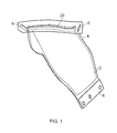
- Figure 1 depicts a body of material and the profile of a nominal machined aerofoil
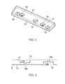
- Figure 2 depicts a datum feature
- Figure 3 depicts a cross-section through the datum feature of Figure 2 ;
- Figure 4 depicts an article mounted to a fixture through datum feature
- FIG. 5 is a perspective view of a fixture in accordance with an embodiment of the invention.
- Figure 6 is an alternative perspective view of the fixture of Figure 5 .
- Figure 1 depicts a finished fan blade 2 within a body of material 4.
- the body of material is indicative of the stock material which is the condition of supply of the component prior to the machining operation. Additional material is provided around the blade to permit the external surface to be machined to a desired tolerance and which leaves at least a minimum material between the inner volume and the external surface.
- the stock material 4 is provided as a laminate of layers and two test pieces 6 are provided in the foot portion of the stock material and which are used to test the weld integrity of the stock. These lie outside the form of the finished blade and are removed during the machining of the stock material to the finished blade form.
- the stock material is also provided with a body, or letterbox, of material 8 beyond the tip of the blade which is machined to assist with the support and alignment of the stock material so that the sides of the blade 4 may be machined in separate operations.
- the Figure shows the letterbox in partially machined form. Beneficially the letterbox can provide both an alignment and clamping location
- the letterbox 8 is shown in more detail in Figure 2 and is provided with a series of datum features provided in a top surface 12 and the bottom surface 14.
- a first set of datum features 18 are provided which are formed in the top surface and have a first portion 18a which is a circular cut-out with a first diameter in the top surface and a second portion 18b which is an aperture extending from the base of the circular cut-out to the bottom surface 14. The diameter of the second portion is less than the diameter of the first portion.
- a second set of datum features 16 are provided which are formed in the bottom surface 14 and have a first portion 16a which is a circular cut-out with a first diameter in the top surface and a second portion 16b which is an aperture extending from the base of the circular cut-out to the top surface 12.
- the diameter of the second portion is less than the diameter of the first portion.
- the first and second datum sets are manufactured sequentially preferably at the stage in the process at which each of the sides are machined.
- the datum features assist in the manufacture of the blade in a number of discrete steps and the first set of datum features 18 are used to determine the location of the second set of datum features 16.
- the foot 20 of the blade is machined in a fixture along with the test pieces 6 and the first side of the letterbox 8.
- the first set of datum features 18 are also machined with the depth of the first portion 18a from the surface 12 being carefully controlled to provide an accurate datum.
- the location of the datum features is controlled relative to the position of the machined foot.
- the blade with the machined foot is then addressed to a further fixture 24 as shown in Figure 4 using the datum features 18.
- Two datum features 18 have a depth selected to locate the blade in a desired orientation on the fixture. The depths may provide two co-planar surfaces on which the blade tip can rest on the fixture.
- the fixture can also be provided with corresponding pads 22 the height of which can be adjusted to ensure that each pad rest on its co-planar surface.
- the second portion 18b of the datum features 18 extends through the letterbox 8 to provide an aperture which is aligned with an aperture 28 in the pad 22.
- a screw 26 is inserted through the aperture 18a and tightened to the pad using a screw thread and a corresponding screw thread on the internal surface of the aperture 28 in the pad. The screw securely bonds the letterbox and hence the blade to fixture 24.
- the surface 4 of the blade to be machined is relatively accurately positioned ready for machining, but fine alignment may be used to further improve the positional accuracy of the blade.
- the surface is then machined.
- the second set of datum features 16 are formed in the letterbox 8.
- the position of the first datum features 18 is known through the positioning of the screw securing the letterbox to the fixture it is possible to accurately align the second datum features to both the first datum feature and the foot 20.
- the blade can be removed from the fixture, turned over and then secured again using a similar method and pads as per the first side.
- the known location of the second datum features 16 relative to the location of the first datum features and the foot permits the second side to be known relatively accurately to reduce alignment time of the machine tool to the second surface 2.
- the second surface is machined and then the letterbox is removed to provide the finished blade.
- the blade surfaces 2, 4 are relatively thin and may be subject to machining chatter or distortion caused by tool pressure. To minimise distortion and improve clamping the fixture is provided, as shown in figure 5 , with a plurality of support pins which are addressable to the surface opposite the surface being machined.
- the pins are driven up to touch the underside of the blade using hydraulic actuation at low pressure, or preferably pneumatic actuation.
- hydraulic actuation at low pressure, or preferably pneumatic actuation.
- air pressure is used with the pressure used being insufficient to cause permanent distortion of the blade even if pressure is applied following first contact.
- the pins are then locked in position using an alternative clamping force, preferably hydraulic, in a direction orthogonal to that required to address the pin to the surface.
- an alternative clamping force preferably hydraulic, in a direction orthogonal to that required to address the pin to the surface.
- a large clamping force can be applied in this second direction as there is no risk of the force distorting the blade.
- An array of pins 30 are used so as to provide a uniform area of support directly opposite to the machining forces.
- the blade can be rigidly secured to the fixture independently of the tool which machines the surfaces. This permits accurate alignment, or determination of the position of the surface to be machined, relative to a datum on the fixture. This measurement can be time consuming which, if performed in the machining tool, can slow production rates below the minimum acceptable.
- the fixture is provided with a plurality of calibration features 40 which are visible to the alignment device after the blade is secured to the fixture.
- the position of the blade on the fixture is controlled to reasonable tolerance due to the datum features 18, 16 and 22 but exact alignment is not required.
- the clamps being provided to grip the component rather than accurately set its position.
- Step 1 a digital model of the component is determined using an optical digitising system using reference point alignment techniques known in the art.
- the model preferably determined before the blade is attached to the fixture a reference point system combines individual measurements into a single co-ordinate system.
- the reference points may be non-contact points and which can be fluorescent, reflective or radiation absorbent features are applied to the component and optionally around the component. Alternatively the individual measurements may be determined by contact techniques such as CMM..
- the reference points may be temporarily secured to the component or may be a permanent feature e.g. a corner, edge or other identifiable feature.
- Sensors are used to digitise an image of the component and the surface data is aligned to the reference points. Where reference points are applied to the component they are captured and digitised with the surface data and become an inherent element of the resultant 3D model.
- the fixture is provided with at least one machine target reference point, Step 2 but preferably at least three are provided to enable accurate triangulation.
- Step 3 the component, or blade is loaded to the fixture using the method described above and clamped.
- a photogrammetry system is used to monitor the distortion of the blade as it is secured to the fixture.
- the distortion can be measured as a deformation vector and the clamping adjusted dynamically to minimise the distortion to below defined limits, preferably 80 microns.
- Output from the photogrammetry system can be used to determine the relationship between the clamped blade and the fixture and identify any change or movement in the pattern of reference points as the blade is clamped or following clamping.
- Fixed photogrammetric reference points 40 which are mounted on pillars are premeasured using a touch probe on the machine tool. Their coordinates are known with respect to the machine co-ordinate system. As the fixture uses a zero point location system it can be repeatedly loaded to the machine tool in a known position. Since the location of the fixture is accurately known because of the zero point location and the location of the component to the fixture is accurately known it is possible to determine the position of the component relative to the machine tool before the fixture is mounted thereto.
- the photogrammetry system is used to measure the assembled set of reference points on the blade as well as the fixed photogrammetric reference points on the fixture to provide mobile reference points, Step 4.
- the fixture and blade is then transferred to the machine tool and the file describing the machine co-ordinates of the fixed photogrammetric reference points of the fixture loaded to provide a number of target reference points.
- Each fixture may be slightly different so it is beneficial to provide a specific file for each fixture.
- the mobile reference points are aligned to the target reference points which are the true machine co-ordinates, Step 5, and the digitised image subsequently aligned to the mobile reference points using the reference points that were captured with it, Step 6.
- an alignment may be calculated which adjusts the co-ordinates of the toolpaths to the true position of the component on the machine tool, Step 7.
- the component may then be machined using the adjusted tool paths, Step 8.
- the point to point alignment is more accurate and robust than point-to-surface alignment.
- time saving since once the clamping has been completed and a measurement of the full set of assembled reference points has been made, the alignment can be calculated and the tool paths specified, adjusted and loaded into the machine tool before the fixture and the component is loaded onto the machine tool.
- any discrepancies above a predetermined threshold between aligned component and the expected location provides an automatic check of the integrity of the fixture points by comparison. Where the discrepancy is above the threshold touch or other contact probes may be used to further check values.
- the approach also supports a more flexible approach to high volume manufacture as no further probing may be needed and a shorter turnaround is possible. Fully automatic machining of the surface may be possible and robot controlled.
Landscapes
- Engineering & Computer Science (AREA)
- Mechanical Engineering (AREA)
- General Engineering & Computer Science (AREA)
- Jigs For Machine Tools (AREA)
- Machine Tool Sensing Apparatuses (AREA)
- Accommodation For Nursing Or Treatment Tables (AREA)
- Turbine Rotor Nozzle Sealing (AREA)
Abstract
Description
- The invention relates to the manufacture of components and particularly the manufacture of aerofoils for gas turbine engines and even more particularly the manufacture of fan blades.
- Aerofoils such as fan blades for a gas turbine engine are often manufactured as what is commonly known in the art as "wide chord blades". The blades, typically formed of titanium, have a leading edge, a trailing edge and pressure and suction flanks extending between the leading and trailing edges and are manufactured from a series of plates which are laminated together before a gas injected between the sheets causes the blade to inflate. The blade is subsequently twisted and the external surfaces machined and polished to its finished form.
- The flanks, leading and trailing edges may need to be machined and it is an object of the present invention to seek to provide an improved method of treating an aerofoil.
- According to a first aspect of the invention there is provided a fixture for securing an aerofoil having a foot, a tip, a first flank and an opposing second flank, the aerofoil, when secured on the fixture presenting the second flank to a machine tool, the fixture having a base supporting a foot clamp for clamping the foot of an aerofoil and a tip clamp for clamping the tip of the aerofoil, and further having an array of supports between the foot clamp and the tip clamp, each support within the array configured to be independently addressable to the first flank when the aerofoil is secured to the fixture.
- Preferably the tip of the aerofoil has a surplus of material with the tip clamp clamping the surplus material.
- Preferably the tip clamp comprises at least one protrusion which engages a recess in the surplus material.
- Each support may be functionally connected to pneumatic or hydraulic actuator.
- Each support may have a locking device which locks the support against the aerofoil flank.
- Preferably the fixture has at least three alignment pillar that is located beyond the array of support pillars. Preferably each of the three alignment pillars has an exposed reference surface.
- According to a second aspect of the invention there is provided a method of securing an aerofoil having a foot, a tip, a first flank and an opposing second flank in a fixture, the fixture having a foot clamp for clamping the foot of an aerofoil and a tip clamp for clamping the tip of the aerofoil, and further having an array of supports between the foot clamp and the tip clamp, each support within the array being independently addressable to one of the aerofoil flanks, the method comprising the step of securing the aerofoil in the fixture using the tip clamp and the foot clamp and addressing each of the supports to a flank of the aerofoil, and locking the respective support once contact of the support to the flank is determined.
- Preferably the contact is determined by a contact sensor.
- The support may be addressable using pneumatics and contact is determined by the pneumatic air pressure.
- The fixture may further comprise at least three pillars that are located on the base beyond the array of support pillars, each pillar providing a calibration feature, the method comprising the step of determining the position of each calibration feature relative to the first flank.
- Preferably the position of each calibration feature relative to the first flank before the supports are addressed to the second flank and after the supports are addressed to the second flank, and comparing the positions to identify differences for indicating distortion in the first flank .
- Each calibration feature may be an exposed reference surface having a photogrammetry marker.
-
Figure 1 depicts a body of material and the profile of a nominal machined aerofoil; -
Figure 2 depicts a datum feature -
Figure 3 depicts a cross-section through the datum feature ofFigure 2 ; -
Figure 4 depicts an article mounted to a fixture through datum feature; -
Figure 5 is a perspective view of a fixture in accordance with an embodiment of the invention -
Figure 6 is an alternative perspective view of the fixture ofFigure 5 . -
Figure 1 depicts a finishedfan blade 2 within a body ofmaterial 4. The body of material is indicative of the stock material which is the condition of supply of the component prior to the machining operation. Additional material is provided around the blade to permit the external surface to be machined to a desired tolerance and which leaves at least a minimum material between the inner volume and the external surface. - The
stock material 4 is provided as a laminate of layers and twotest pieces 6 are provided in the foot portion of the stock material and which are used to test the weld integrity of the stock. These lie outside the form of the finished blade and are removed during the machining of the stock material to the finished blade form. - The stock material is also provided with a body, or letterbox, of
material 8 beyond the tip of the blade which is machined to assist with the support and alignment of the stock material so that the sides of theblade 4 may be machined in separate operations. The Figure shows the letterbox in partially machined form. Beneficially the letterbox can provide both an alignment and clamping location - The
letterbox 8 is shown in more detail inFigure 2 and is provided with a series of datum features provided in atop surface 12 and thebottom surface 14. A first set ofdatum features 18 are provided which are formed in the top surface and have afirst portion 18a which is a circular cut-out with a first diameter in the top surface and asecond portion 18b which is an aperture extending from the base of the circular cut-out to thebottom surface 14. The diameter of the second portion is less than the diameter of the first portion. - A second set of
datum features 16 are provided which are formed in thebottom surface 14 and have afirst portion 16a which is a circular cut-out with a first diameter in the top surface and asecond portion 16b which is an aperture extending from the base of the circular cut-out to thetop surface 12. The diameter of the second portion is less than the diameter of the first portion. - The first and second datum sets are manufactured sequentially preferably at the stage in the process at which each of the sides are machined. The datum features assist in the manufacture of the blade in a number of discrete steps and the first set of
datum features 18 are used to determine the location of the second set ofdatum features 16. - In the first step of the exemplary method the
foot 20 of the blade is machined in a fixture along with thetest pieces 6 and the first side of theletterbox 8. During this step the first set ofdatum features 18 are also machined with the depth of thefirst portion 18a from thesurface 12 being carefully controlled to provide an accurate datum. The location of the datum features is controlled relative to the position of the machined foot. - The blade with the machined foot is then addressed to a
further fixture 24 as shown inFigure 4 using the datum features 18. Twodatum features 18 have a depth selected to locate the blade in a desired orientation on the fixture. The depths may provide two co-planar surfaces on which the blade tip can rest on the fixture. The fixture can also be provided withcorresponding pads 22 the height of which can be adjusted to ensure that each pad rest on its co-planar surface. - The
second portion 18b of thedatum features 18 extends through theletterbox 8 to provide an aperture which is aligned with anaperture 28 in thepad 22. Ascrew 26 is inserted through theaperture 18a and tightened to the pad using a screw thread and a corresponding screw thread on the internal surface of theaperture 28 in the pad. The screw securely bonds the letterbox and hence the blade tofixture 24. - As the location of the datum features 18 relative to the foot is known the
surface 4 of the blade to be machined is relatively accurately positioned ready for machining, but fine alignment may be used to further improve the positional accuracy of the blade. The surface is then machined. As part of the machining step the second set ofdatum features 16 are formed in theletterbox 8. As the position of thefirst datum features 18 is known through the positioning of the screw securing the letterbox to the fixture it is possible to accurately align the second datum features to both the first datum feature and thefoot 20. - Following completion of the first side machining the blade can be removed from the fixture, turned over and then secured again using a similar method and pads as per the first side. Beneficially the known location of the second datum features 16 relative to the location of the first datum features and the foot permits the second side to be known relatively accurately to reduce alignment time of the machine tool to the
second surface 2. The second surface is machined and then the letterbox is removed to provide the finished blade. - The
blade surfaces figure 5 , with a plurality of support pins which are addressable to the surface opposite the surface being machined. - Following secure clamping of the blade at the foot and letterbox the pins are driven up to touch the underside of the blade using hydraulic actuation at low pressure, or preferably pneumatic actuation. Preferably air pressure is used with the pressure used being insufficient to cause permanent distortion of the blade even if pressure is applied following first contact. The pins are then locked in position using an alternative clamping force, preferably hydraulic, in a direction orthogonal to that required to address the pin to the surface. Beneficially a large clamping force can be applied in this second direction as there is no risk of the force distorting the blade.
- An array of
pins 30 are used so as to provide a uniform area of support directly opposite to the machining forces. - One of the benefits of the described clamping system is that the blade can be rigidly secured to the fixture independently of the tool which machines the surfaces. This permits accurate alignment, or determination of the position of the surface to be machined, relative to a datum on the fixture. This measurement can be time consuming which, if performed in the machining tool, can slow production rates below the minimum acceptable.
- The fixture is provided with a plurality of calibration features 40 which are visible to the alignment device after the blade is secured to the fixture. The position of the blade on the fixture is controlled to reasonable tolerance due to the datum features 18, 16 and 22 but exact alignment is not required. The clamps being provided to grip the component rather than accurately set its position.
- A schematic of the process steps for the preferred method of determining the machining process is shown in
Figure 7 . In Step 1 a digital model of the component is determined using an optical digitising system using reference point alignment techniques known in the art. The model, preferably determined before the blade is attached to the fixture a reference point system combines individual measurements into a single co-ordinate system. The reference points may be non-contact points and which can be fluorescent, reflective or radiation absorbent features are applied to the component and optionally around the component. Alternatively the individual measurements may be determined by contact techniques such as CMM.. The reference points may be temporarily secured to the component or may be a permanent feature e.g. a corner, edge or other identifiable feature. - Sensors are used to digitise an image of the component and the surface data is aligned to the reference points. Where reference points are applied to the component they are captured and digitised with the surface data and become an inherent element of the resultant 3D model.
- The fixture is provided with at least one machine target reference point,
Step 2 but preferably at least three are provided to enable accurate triangulation. InStep 3, the component, or blade is loaded to the fixture using the method described above and clamped. A photogrammetry system is used to monitor the distortion of the blade as it is secured to the fixture. The distortion can be measured as a deformation vector and the clamping adjusted dynamically to minimise the distortion to below defined limits, preferably 80 microns. - Output from the photogrammetry system can be used to determine the relationship between the clamped blade and the fixture and identify any change or movement in the pattern of reference points as the blade is clamped or following clamping.
- Fixed
photogrammetric reference points 40 which are mounted on pillars are premeasured using a touch probe on the machine tool. Their coordinates are known with respect to the machine co-ordinate system. As the fixture uses a zero point location system it can be repeatedly loaded to the machine tool in a known position. Since the location of the fixture is accurately known because of the zero point location and the location of the component to the fixture is accurately known it is possible to determine the position of the component relative to the machine tool before the fixture is mounted thereto. - Once the blade has been fully clamped the photogrammetry system is used to measure the assembled set of reference points on the blade as well as the fixed photogrammetric reference points on the fixture to provide mobile reference points,
Step 4. - The fixture and blade is then transferred to the machine tool and the file describing the machine co-ordinates of the fixed photogrammetric reference points of the fixture loaded to provide a number of target reference points. Each fixture may be slightly different so it is beneficial to provide a specific file for each fixture.
- The mobile reference points are aligned to the target reference points which are the true machine co-ordinates,
Step 5, and the digitised image subsequently aligned to the mobile reference points using the reference points that were captured with it,Step 6. - Beneficially, this aligns the digitised image to the machine co-ordinates and represents the true location of the blade with respect to the machine co-ordinates. Once this is known an alignment may be calculated which adjusts the co-ordinates of the toolpaths to the true position of the component on the machine tool,
Step 7. The component may then be machined using the adjusted tool paths,Step 8. - Automatic check of integrity of the fixture points by comparison. Can then touch probe to confirm/ check etc.
- One of the many advantages is that the point to point alignment is more accurate and robust than point-to-surface alignment. In addition there is significant time saving since once the clamping has been completed and a measurement of the full set of assembled reference points has been made, the alignment can be calculated and the tool paths specified, adjusted and loaded into the machine tool before the fixture and the component is loaded onto the machine tool. As a further advantage any discrepancies above a predetermined threshold between aligned component and the expected location provides an automatic check of the integrity of the fixture points by comparison. Where the discrepancy is above the threshold touch or other contact probes may be used to further check values. The approach also supports a more flexible approach to high volume manufacture as no further probing may be needed and a shorter turnaround is possible. Fully automatic machining of the surface may be possible and robot controlled.
- Although the invention has been described with respect to fan blades it is equally applicable to other aerofoil types such as compressor blades and vane, turbine blades and vanes , aircraft wings and ailerons.
Claims (13)
- A fixture (24) for securing an aerofoil (4) having a foot (20), a tip (8), a first flank and an opposing second flank, the aerofoil, when secured on the fixture presenting the second flank to a machine tool, the fixture having a base supporting
a foot clamp for clamping the foot of an aerofoil and a tip clamp (22) for clamping the tip of the aerofoil,
and further having an array of supports (30) between the foot clamp and the tip clamp, each support within the array configured to be independently addressable to the first flank when the aerofoil is secured to the fixture. - A fixture according to claim 1, wherein the tip of the aerofoil has a surplus of material with the tip clamp configured to clamp the surplus material.
- A fixture according to claim 2, wherein the tip clamp comprises at least one protrusion configured to engage a recess in the surplus material.
- A fixture according to claim1, wherein each support is functionally connected to pneumatic or hydraulic actuator.
- A fixture according to claim 4, wherein each support has a locking device to lock the support against movement and is configured to lock the support against the first aerofoil flank.
- A fixture according to any preceding claim further comprising at least three pillars (40) that are located on the base beyond the array of supports (30) and visible after the aerofoil is secured , each pillar providing a calibration feature.
- A fixture according to claim 6, further comprising an aerofoil, wherein each calibration feature is an exposed reference surface having a photogrammetry marker.
- A method of securing an aerofoil (4) in a fixture (24) to present a first flank to a machine tool, the aerofoil having a foot, a tip, and a second flank opposing the first flank, the fixture having a base supporting a foot clamp for clamping the foot of an aerofoil and a tip clamp for clamping the tip of the aerofoil, and further having an array of supports between the foot clamp and the tip clamp, each support within the array being independently addressable to one of the aerofoil flanks, the method comprising the step of securing the aerofoil in the fixture using the tip clamp and the foot clamp and addressing each of the supports to the second flank of the aerofoil, and locking the respective support once contact of the support to the flank is determined.
- A method according to claim 8, wherein the contact is determined by a contact sensor.
- A method according to claim 8, wherein the support is addressable using pneumatics and contact is determined by a pneumatic air pressure.
- A method according to claim 8, wherein the fixture further comprises at least three pillars that are located on the base beyond the array of support pillars, each pillar providing a calibration feature, the method comprising the step of determining the position of each calibration feature relative to the first flank.
- A method according to claim 11, further comprising the step of determining the position of each calibration feature relative to the first flank before the supports are addressed to the second flank and after the supports are addressed to the second flank, and comparing the positions to identify differences for indicating distortion in the first flank .
- A method according to claim 11, wherein each calibration feature is an exposed reference surface having a photogrammetry marker.
Applications Claiming Priority (1)
| Application Number | Priority Date | Filing Date | Title |
|---|---|---|---|
| GB1215624.6A GB2505496A (en) | 2012-09-03 | 2012-09-03 | Fixture and method for securing an aerofoil |
Publications (2)
| Publication Number | Publication Date |
|---|---|
| EP2703118A2 true EP2703118A2 (en) | 2014-03-05 |
| EP2703118A3 EP2703118A3 (en) | 2014-06-25 |
Family
ID=47075130
Family Applications (1)
| Application Number | Title | Priority Date | Filing Date |
|---|---|---|---|
| EP13181457.6A Withdrawn EP2703118A3 (en) | 2012-09-03 | 2013-08-23 | Fixture and method for securing an aerofoil |
Country Status (4)
| Country | Link |
|---|---|
| US (1) | US9441493B2 (en) |
| EP (1) | EP2703118A3 (en) |
| GB (1) | GB2505496A (en) |
| SG (1) | SG2013064431A (en) |
Cited By (6)
| Publication number | Priority date | Publication date | Assignee | Title |
|---|---|---|---|---|
| CN104097098A (en) * | 2014-07-07 | 2014-10-15 | 西安工业大学 | Multipoint positioning method for large curved-surface thin-walled workpieces |
| CN104191264A (en) * | 2014-08-06 | 2014-12-10 | 哈尔滨汽轮机厂有限责任公司 | Clamping and positioning device for machining gas turbine power turbine guide vane datum face |
| CN108127431A (en) * | 2017-10-31 | 2018-06-08 | 武汉船用机械有限责任公司 | A kind of blade positioning tool |
| CN108356786A (en) * | 2018-03-04 | 2018-08-03 | 姚森 | A kind of adaptive clamp system of special-shaped workpiece fixture |
| US10105804B2 (en) | 2014-10-15 | 2018-10-23 | United Technologies Corporation | Fixture system and method for securing an airfoil during material removal operations |
| CN110509089A (en) * | 2019-09-05 | 2019-11-29 | 中国航空制造技术研究院 | It is a kind of for processing the vibration damping tooling of wide-chord hollow fan blade |
Families Citing this family (10)
| Publication number | Priority date | Publication date | Assignee | Title |
|---|---|---|---|---|
| FR2976836B1 (en) * | 2011-06-21 | 2013-06-21 | Snecma | DEVICE FOR MAINTAINING A TURBOMACHINE BLADE FOR MACHINING |
| CN103909432B (en) * | 2014-04-01 | 2016-08-17 | 西北工业大学 | Blade of aviation engine processing on-line measurement modular fixture |
| CN104191271B (en) * | 2014-09-01 | 2016-08-03 | 宁夏共享精密加工有限公司 | A kind of large thin-wall grinder shell cover anti-deformation support top device and method |
| GB2546107A (en) * | 2016-01-11 | 2017-07-12 | Rolls Royce Plc | Methods and apparatus for enabling determination of a position of an object |
| GB201608639D0 (en) * | 2016-05-17 | 2016-06-29 | Rolls Royce Plc | Fixture for holding a complex-shaped part during a machining operation |
| CN106378653B (en) * | 2016-11-15 | 2018-04-03 | 苏州亨达尔工业材料有限公司 | A kind of tool of the non-horizontal special-shaped trim panel of fixation |
| CN110052925A (en) * | 2019-05-30 | 2019-07-26 | 南京赛达机械制造有限公司 | A kind of turbine Blade Machining platform |
| CN111570946B (en) * | 2020-06-30 | 2021-10-08 | 中国航发动力股份有限公司 | Positioning device for linear cutting of strip-shaped support plate |
| CN112496786A (en) * | 2020-11-16 | 2021-03-16 | 中国航发沈阳黎明航空发动机有限责任公司 | Integrated tool for machining blade air film hole and manufacturing process thereof |
| US12109622B1 (en) * | 2023-03-14 | 2024-10-08 | Rtx Corporation | Spindles peening offset fixture for CNC turning |
Family Cites Families (14)
| Publication number | Priority date | Publication date | Assignee | Title |
|---|---|---|---|---|
| US2565925A (en) * | 1946-04-10 | 1951-08-28 | Rolls Royce | Method of manufacturing guide vanes for axial flow turbines and compressors |
| US2722867A (en) | 1948-11-06 | 1955-11-08 | Thompson Prod Inc | Method of and apparatus for machining blade airfoil surfaces |
| US3866305A (en) * | 1972-08-14 | 1975-02-18 | Tool Research & Engineering Co | Internally stiffened contoured shell structure and method for fabricating same |
| US3818646A (en) * | 1973-01-12 | 1974-06-25 | Trw Inc | Fixture for holding precisely shaped parts |
| US4033569A (en) * | 1976-10-15 | 1977-07-05 | Dunn Garf L | Deformation-preventing workpiece-holding fixture for machine tools |
| US4685660A (en) * | 1986-02-13 | 1987-08-11 | United Technologies Corporation | Workholder for securing a workpiece thereto |
| WO1994011795A1 (en) * | 1992-11-19 | 1994-05-26 | United Technologies Corporation | Method for cnc machining |
| DE10026829C2 (en) | 2000-05-30 | 2003-02-20 | Arthur Prib | Device for clamping a workpiece with an uneven surface |
| JP3647378B2 (en) * | 2001-03-02 | 2005-05-11 | キヤノン株式会社 | Shape measuring apparatus and measuring method using multiprobe |
| DE10206447B4 (en) * | 2002-02-11 | 2004-06-03 | Mtu Aero Engines Gmbh | Method and device for holding a metallic component to be connected and method for connecting a metallic component to another component |
| US6993821B2 (en) * | 2002-12-30 | 2006-02-07 | General Electric Company | Manufacturing cell using tooling apparatus |
| GB2458738A (en) | 2008-04-04 | 2009-10-07 | Heller Machine Tools Ltd | Holding device for non planar work piece |
| DE102010018284B4 (en) * | 2010-04-26 | 2013-05-29 | Hamuel Maschinenbau Gmbh & Co. Kg | Turbine blade blank, and method and apparatus for machining a turbine blade blank |
| FR2976203B1 (en) | 2011-06-07 | 2017-01-06 | Snecma | PROCESS FOR MACHINING A COMPOSITE AUBE |
-
2012
- 2012-09-03 GB GB1215624.6A patent/GB2505496A/en not_active Withdrawn
-
2013
- 2013-08-22 US US13/973,464 patent/US9441493B2/en active Active
- 2013-08-23 EP EP13181457.6A patent/EP2703118A3/en not_active Withdrawn
- 2013-08-26 SG SG2013064431A patent/SG2013064431A/en unknown
Cited By (7)
| Publication number | Priority date | Publication date | Assignee | Title |
|---|---|---|---|---|
| CN104097098A (en) * | 2014-07-07 | 2014-10-15 | 西安工业大学 | Multipoint positioning method for large curved-surface thin-walled workpieces |
| CN104191264A (en) * | 2014-08-06 | 2014-12-10 | 哈尔滨汽轮机厂有限责任公司 | Clamping and positioning device for machining gas turbine power turbine guide vane datum face |
| CN104191264B (en) * | 2014-08-06 | 2016-06-15 | 哈尔滨汽轮机厂有限责任公司 | A kind of processing Gas Turbine Power turbine guide vane sheet reference plane clamping and positioning device |
| US10105804B2 (en) | 2014-10-15 | 2018-10-23 | United Technologies Corporation | Fixture system and method for securing an airfoil during material removal operations |
| CN108127431A (en) * | 2017-10-31 | 2018-06-08 | 武汉船用机械有限责任公司 | A kind of blade positioning tool |
| CN108356786A (en) * | 2018-03-04 | 2018-08-03 | 姚森 | A kind of adaptive clamp system of special-shaped workpiece fixture |
| CN110509089A (en) * | 2019-09-05 | 2019-11-29 | 中国航空制造技术研究院 | It is a kind of for processing the vibration damping tooling of wide-chord hollow fan blade |
Also Published As
| Publication number | Publication date |
|---|---|
| EP2703118A3 (en) | 2014-06-25 |
| US20140064974A1 (en) | 2014-03-06 |
| US9441493B2 (en) | 2016-09-13 |
| SG2013064431A (en) | 2014-04-28 |
| GB2505496A (en) | 2014-03-05 |
| GB201215624D0 (en) | 2012-10-17 |
Similar Documents
| Publication | Publication Date | Title |
|---|---|---|
| US9441493B2 (en) | Fixture and method for securing an aerofoil | |
| US9291058B2 (en) | Machining process and apparatus for machining | |
| CN107303643B (en) | Error identification method and error identification system of machine tool | |
| US7869899B2 (en) | Machine tool method | |
| CN116529680B (en) | Measuring body for checking a geometric deviation of a three-axis machine tool, and method for compensating a geometric deviation of a three-axis machine tool | |
| US20110295408A1 (en) | Process for positioning a workpiece | |
| US6985238B2 (en) | Non-contact measurement system for large airfoils | |
| US20110033254A1 (en) | System And Method Of Locating Relative Positions Of Objects | |
| CN108917548A (en) | Turbo blade Surface inspection method and measuring device | |
| CN115922439B (en) | Machining accuracy detection method for CNC five-axis machine tools | |
| CN111329183A (en) | Shoe last extension as an origin | |
| CN109282772B (en) | Method for determining coordinate system of blank workpiece of cylinder cover | |
| CN112595281B (en) | Method and medium for rapidly measuring surface profile of workpiece | |
| US10222193B2 (en) | Method and apparatus for inspecting workpieces | |
| CN110645935A (en) | Accurate calibration method for installation offset of integrated displacement sensor of numerical control rotating shaft | |
| CN214747718U (en) | High-reliability inclined hole angle measuring clamp | |
| CN214702080U (en) | A go-stop gauge for the profile inspection of the compressor dovetail tongue and groove | |
| TWI849877B (en) | Measuring body for verifying geometrical deviations of a 3-axis machine tool, 3-axis machine tool, and method for compensating geometrical deviations of a 3-axis machine tool | |
| CN224034533U (en) | Device for determining the location of strain gauge patches on aero-engine blades | |
| CN114279301B (en) | Inner wall measurement system and measurement method based on deep sagittal height workpiece | |
| CN112683568B (en) | A standard block and attitude adjustment method for AC turntable posture adjustment in multi-axis machining | |
| CN120010378A (en) | A CNC machine tool finishing method for casting parts | |
| Aguado et al. | Design of a Test Part for Verification and Validation of a Three Linear Axes Machine Tool | |
| Jankowski et al. | Master artifacts for testing the performance of probes for CNC machine tools | |
| CN116748546A (en) | A method for drilling center holes in components during assembly |
Legal Events
| Date | Code | Title | Description |
|---|---|---|---|
| AK | Designated contracting states |
Kind code of ref document: A2 Designated state(s): AL AT BE BG CH CY CZ DE DK EE ES FI FR GB GR HR HU IE IS IT LI LT LU LV MC MK MT NL NO PL PT RO RS SE SI SK SM TR |
|
| AX | Request for extension of the european patent |
Extension state: BA ME |
|
| PUAI | Public reference made under article 153(3) epc to a published international application that has entered the european phase |
Free format text: ORIGINAL CODE: 0009012 |
|
| PUAL | Search report despatched |
Free format text: ORIGINAL CODE: 0009013 |
|
| AK | Designated contracting states |
Kind code of ref document: A3 Designated state(s): AL AT BE BG CH CY CZ DE DK EE ES FI FR GB GR HR HU IE IS IT LI LT LU LV MC MK MT NL NO PL PT RO RS SE SI SK SM TR |
|
| AX | Request for extension of the european patent |
Extension state: BA ME |
|
| RIC1 | Information provided on ipc code assigned before grant |
Ipc: B23Q 1/03 20060101AFI20140516BHEP Ipc: B23Q 17/22 20060101ALI20140516BHEP Ipc: B23Q 3/06 20060101ALI20140516BHEP |
|
| STAA | Information on the status of an ep patent application or granted ep patent |
Free format text: STATUS: THE APPLICATION IS DEEMED TO BE WITHDRAWN |
|
| 18D | Application deemed to be withdrawn |
Effective date: 20150106 |