EP2703036A2 - Catheter grip and catheter assembly - Google Patents
Catheter grip and catheter assembly Download PDFInfo
- Publication number
- EP2703036A2 EP2703036A2 EP13181106.9A EP13181106A EP2703036A2 EP 2703036 A2 EP2703036 A2 EP 2703036A2 EP 13181106 A EP13181106 A EP 13181106A EP 2703036 A2 EP2703036 A2 EP 2703036A2
- Authority
- EP
- European Patent Office
- Prior art keywords
- catheter
- head portion
- grip
- body portion
- shaft
- Prior art date
- Legal status (The legal status is an assumption and is not a legal conclusion. Google has not performed a legal analysis and makes no representation as to the accuracy of the status listed.)
- Granted
Links
Images



Classifications
-
- A—HUMAN NECESSITIES
- A61—MEDICAL OR VETERINARY SCIENCE; HYGIENE
- A61M—DEVICES FOR INTRODUCING MEDIA INTO, OR ONTO, THE BODY; DEVICES FOR TRANSDUCING BODY MEDIA OR FOR TAKING MEDIA FROM THE BODY; DEVICES FOR PRODUCING OR ENDING SLEEP OR STUPOR
- A61M25/00—Catheters; Hollow probes
- A61M25/002—Packages specially adapted therefor ; catheter kit packages
-
- A—HUMAN NECESSITIES
- A61—MEDICAL OR VETERINARY SCIENCE; HYGIENE
- A61F—FILTERS IMPLANTABLE INTO BLOOD VESSELS; PROSTHESES; DEVICES PROVIDING PATENCY TO, OR PREVENTING COLLAPSING OF, TUBULAR STRUCTURES OF THE BODY, e.g. STENTS; ORTHOPAEDIC, NURSING OR CONTRACEPTIVE DEVICES; FOMENTATION; TREATMENT OR PROTECTION OF EYES OR EARS; BANDAGES, DRESSINGS OR ABSORBENT PADS; FIRST-AID KITS
- A61F2/00—Filters implantable into blood vessels; Prostheses, i.e. artificial substitutes or replacements for parts of the body; Appliances for connecting them with the body; Devices providing patency to, or preventing collapsing of, tubular structures of the body, e.g. stents
- A61F2/95—Instruments specially adapted for placement or removal of stents or stent-grafts
- A61F2/9517—Instruments specially adapted for placement or removal of stents or stent-grafts handle assemblies therefor
-
- A—HUMAN NECESSITIES
- A61—MEDICAL OR VETERINARY SCIENCE; HYGIENE
- A61M—DEVICES FOR INTRODUCING MEDIA INTO, OR ONTO, THE BODY; DEVICES FOR TRANSDUCING BODY MEDIA OR FOR TAKING MEDIA FROM THE BODY; DEVICES FOR PRODUCING OR ENDING SLEEP OR STUPOR
- A61M25/00—Catheters; Hollow probes
- A61M25/0017—Catheters; Hollow probes specially adapted for long-term hygiene care, e.g. urethral or indwelling catheters to prevent infections
-
- A—HUMAN NECESSITIES
- A61—MEDICAL OR VETERINARY SCIENCE; HYGIENE
- A61M—DEVICES FOR INTRODUCING MEDIA INTO, OR ONTO, THE BODY; DEVICES FOR TRANSDUCING BODY MEDIA OR FOR TAKING MEDIA FROM THE BODY; DEVICES FOR PRODUCING OR ENDING SLEEP OR STUPOR
- A61M25/00—Catheters; Hollow probes
- A61M25/01—Introducing, guiding, advancing, emplacing or holding catheters
-
- A—HUMAN NECESSITIES
- A61—MEDICAL OR VETERINARY SCIENCE; HYGIENE
- A61M—DEVICES FOR INTRODUCING MEDIA INTO, OR ONTO, THE BODY; DEVICES FOR TRANSDUCING BODY MEDIA OR FOR TAKING MEDIA FROM THE BODY; DEVICES FOR PRODUCING OR ENDING SLEEP OR STUPOR
- A61M25/00—Catheters; Hollow probes
- A61M25/01—Introducing, guiding, advancing, emplacing or holding catheters
- A61M25/0105—Steering means as part of the catheter or advancing means; Markers for positioning
- A61M25/0111—Aseptic insertion devices
-
- A—HUMAN NECESSITIES
- A61—MEDICAL OR VETERINARY SCIENCE; HYGIENE
- A61M—DEVICES FOR INTRODUCING MEDIA INTO, OR ONTO, THE BODY; DEVICES FOR TRANSDUCING BODY MEDIA OR FOR TAKING MEDIA FROM THE BODY; DEVICES FOR PRODUCING OR ENDING SLEEP OR STUPOR
- A61M25/00—Catheters; Hollow probes
- A61M25/01—Introducing, guiding, advancing, emplacing or holding catheters
- A61M25/0105—Steering means as part of the catheter or advancing means; Markers for positioning
- A61M25/0113—Mechanical advancing means, e.g. catheter dispensers
-
- A—HUMAN NECESSITIES
- A61—MEDICAL OR VETERINARY SCIENCE; HYGIENE
- A61M—DEVICES FOR INTRODUCING MEDIA INTO, OR ONTO, THE BODY; DEVICES FOR TRANSDUCING BODY MEDIA OR FOR TAKING MEDIA FROM THE BODY; DEVICES FOR PRODUCING OR ENDING SLEEP OR STUPOR
- A61M25/00—Catheters; Hollow probes
- A61M25/01—Introducing, guiding, advancing, emplacing or holding catheters
- A61M25/0105—Steering means as part of the catheter or advancing means; Markers for positioning
- A61M25/013—One-way gripping collars
-
- A—HUMAN NECESSITIES
- A61—MEDICAL OR VETERINARY SCIENCE; HYGIENE
- A61M—DEVICES FOR INTRODUCING MEDIA INTO, OR ONTO, THE BODY; DEVICES FOR TRANSDUCING BODY MEDIA OR FOR TAKING MEDIA FROM THE BODY; DEVICES FOR PRODUCING OR ENDING SLEEP OR STUPOR
- A61M2210/00—Anatomical parts of the body
- A61M2210/10—Trunk
- A61M2210/1078—Urinary tract
- A61M2210/1085—Bladder
-
- A—HUMAN NECESSITIES
- A61—MEDICAL OR VETERINARY SCIENCE; HYGIENE
- A61M—DEVICES FOR INTRODUCING MEDIA INTO, OR ONTO, THE BODY; DEVICES FOR TRANSDUCING BODY MEDIA OR FOR TAKING MEDIA FROM THE BODY; DEVICES FOR PRODUCING OR ENDING SLEEP OR STUPOR
- A61M2210/00—Anatomical parts of the body
- A61M2210/10—Trunk
- A61M2210/1078—Urinary tract
- A61M2210/1089—Urethra
-
- A—HUMAN NECESSITIES
- A61—MEDICAL OR VETERINARY SCIENCE; HYGIENE
- A61M—DEVICES FOR INTRODUCING MEDIA INTO, OR ONTO, THE BODY; DEVICES FOR TRANSDUCING BODY MEDIA OR FOR TAKING MEDIA FROM THE BODY; DEVICES FOR PRODUCING OR ENDING SLEEP OR STUPOR
- A61M2210/00—Anatomical parts of the body
- A61M2210/10—Trunk
- A61M2210/1078—Urinary tract
- A61M2210/1089—Urethra
- A61M2210/1096—Male
-
- A—HUMAN NECESSITIES
- A61—MEDICAL OR VETERINARY SCIENCE; HYGIENE
- A61M—DEVICES FOR INTRODUCING MEDIA INTO, OR ONTO, THE BODY; DEVICES FOR TRANSDUCING BODY MEDIA OR FOR TAKING MEDIA FROM THE BODY; DEVICES FOR PRODUCING OR ENDING SLEEP OR STUPOR
- A61M25/00—Catheters; Hollow probes
- A61M25/01—Introducing, guiding, advancing, emplacing or holding catheters
- A61M25/09—Guide wires
- A61M25/09041—Mechanisms for insertion of guide wires
Definitions
- the present invention relates to a catheter grip and catheter assembly.
- the invention relates to a catheter grip in the form of a resiliently biased grip that assists with insertion of the catheter, and catheters provided with such a catheter grip.
- Urinary catheters are known and generally include a latex, polyurethane, or silicone tube that is inserted into a patient's bladder via the urethra. Catheterisation allows the patient's urine to drain freely from the bladder for collection. Urinary catheters may also be used to inject liquids used for treatment or diagnosis of bladder conditions. A clinician or nurse usually performs the catheterisation procedure, but self-catheterisation is also possible. If long term catheterisation is needed, catheters that facilitate self-catheterisation are most desirable to give patients a greater degree of independence.
- Urinary catheters may be permanent (indwelling catheters), or may be intermittent and removed after each catheterisation.
- a Foley catheter indwelling urinary catheter
- the balloons typically come in two different sizes: 5-10 ml and 30 ml and are commonly made in silicone rubber or natural rubber.
- An intermittent catheter, or Robinson catheter is a flexible catheter used for short term drainage of urine. Unlike the Foley catheter, it has no balloon on its tip and therefore cannot stay in place unaided. These can be non-coated or coated, for example they may be coated with a hydrophilic coating, and are generally packaged ready for use.
- Coudé catheters are designed with a curved tip that makes it easier to pass the catheter through the curvature of the prostatic urethra.
- Hematuria (or haematuria) catheters are a type of Foley catheter used for Post-TURP hemostasis. This is useful following endoscopic surgical procedures, or in the case of gross hematuria. There are both two-way and three-way hematuria catheters (i.e. double and triple lumen). External, Texas, urisheath, and condom catheters are generally used for incontinent males and carry a lower risk of infection than an indwelling catheter.
- a topical anesthetic is sometimes used.
- catheterisation is performed as a sterile medical procedure by trained, qualified personnel, using equipment designed for this purpose.
- intermittent self-catheterisation patients are trained to perform the procedure themselves. Intermittent self-catheterisation is performed by the patient four to six times a day, using a clean technique in most cases. Incorrect technique may cause trauma to the urethra or prostate (male), urinary tract infection, or a paraphimosis in the uncircumcised male.
- intermittent catheterisation IC is a standard method for bladder emptying.
- the technique is safe and effective and results in improved kidney and upper urinary tract status, lessening of vesicoureteral reflux and amelioration of continence.
- patient quality of life is enhanced by the increased independence and security offered by self-catheterisation.
- the catheter In order to maximise the potential for sterile insertion of catheters and thereby minimise the chances of urinary tract infection during self-catheterisation, a number of designs for catheter packaging have been proposed.
- the designs generally aim to remove the need for direct physical contact with the catheter during insertion.
- the catheter is packaged within a bag from which it is fed by a user via indirect contact through the bag.
- the bag may contain a lubricant to assist with feeding of the catheter.
- the catheter is removable from a package and is provided with a sleeve through which the catheter may be fed. In this example, a user pinches the sleeve to indirectly engage the catheter and facilitate insertion.
- the invention provides a catheter grip for a catheter shaft, the catheter grip comprising:
- mechanism includes one or more parts that act to achieve a desired result, in this case biasing of the body portion and head portion of the catheter grip away from one another.
- the term is not intended to be limited to examples that require two or more interacting parts.
- biasing mechanism is not particularly limited, provided the body portion and head portion are biased away from one another. As will be discussed below, this biasing mechanism makes feeding of a catheter shaft passing through the catheter grip easier, particularly for patients who have limited or diminished hand or arm function. In particular, single handed operation may be achieved.
- the biasing mechanism is disposed between the body portion and the head portion.
- the form of biasing mechanism is not particularly limited, provided it achieves the requisite function.
- the biasing mechanism may include a spring mechanism.
- the biasing mechanism comprises at least two laterally spaced walls extending between the body portion and the head portion, the laterally spaced walls being resiliently deformable to provide the biasing.
- Each of the laterally spaced walls may comprise a weakened or diminished portion at or around a longitudinal mid-point thereof such that, in use, as the body portion is forced towards the head portion the laterally spaced walls flex outwardly to provide the biasing.
- the body portion comprises two opposed gripping surfaces that are resiliently compressible towards one another to facilitate gripping of the catheter shaft by a user. Direct contact with the catheter shaft is thereby avoided and the risk of infection reduced.
- the body portion may comprise opposed longitudinal walls that extend between edges of the opposed gripping surfaces.
- opposed gripping surfaces are provided and the biasing mechanism comprises at least two laterally spaced walls extending between the body portion and the head portion in the same plane as the opposing gripping surfaces, the laterally spaced walls being resiliently deformable to provide the biasing, as discussed above.
- the head portion comprises a collar.
- the biasing mechanism comprises at least two laterally spaced walls extending between the body portion and the head portion, the laterally spaced walls are connected directly to, or are integral with the collar.
- the head portion includes a shaft feed extending from the collar through which the catheter shaft is fed.
- the shaft feed is disposed on a feed insert that is adapted to be inserted into the collar of the head portion, or which is disposed on the collar (i.e. surrounding the collar).
- the feed insert may comprise a tubular portion having at least one ridge, the tubular portion being received by the collar of the head portion, an abutment having an abutment surface which abuts the collar of the head portion, and the shaft feed which extends from an outer face of the abutment.
- the body portion, head portion and biasing mechanism are integral with one another to provide the catheter grip.
- the catheter grip may comprise an injection moulded integral unit.
- the catheter grip may be produced by any suitable method and is not so limited.
- Another aspect of the present invention relates to a catheter assembly comprising:
- the biasing mechanism may be disposed between the body portion and the head portion.
- the biasing mechanism may comprise at least two laterally spaced walls extending between the body portion and the head portion, the laterally spaced walls being resiliently deformable to provide the biasing.
- each of the laterally space walls comprises a weakened or diminished portion at or around a longitudinal mid-point thereof such that, in use, as the body portion is forced towards the head portion the laterally spaced walls flex outwardly to provide the biasing.
- the body portion may comprise two opposed gripping surfaces that are resiliently compressible towards one another to facilitate gripping of the catheter shaft by a user.
- the body portion may comprise opposed longitudinal walls that extend between edges of the opposed gripping surfaces.
- the gripping surfaces are provided and the biasing mechanism includes opposed and laterally spaced walls that extend between the body portion and the head portion, and which are in the same plane as the gripping surfaces.
- the head portion comprises a collar as discussed above.
- the head portion may also comprise a shaft feed extending from the collar through which the catheter shaft is fed.
- the shaft feed may be disposed on a feed insert that is adapted to be inserted into or onto the collar of the head portion.
- the feed insert may comprise a tubular portion having at least one ridge, the tubular portion being received by the collar of the head portion, an abutment having an abutment surface which abuts the collar of the head portion, and the shaft feed which extends from an outer face of the abutment.
- the body portion, head portion and biasing mechanism may be integral with one another to provide the catheter grip.
- the drainage outlet may comprise a catheter funnel, or other form of outlet employed in the art.
- the at least one drainage inlet of the catheter shaft may be any that are currently available in the art, for example the at least one drainage inlet may comprise at least one eyelet.
- the present invention provides a catheter assembly and catheter grip.
- the invention relates to catheters provided with a resiliently biased grip that assists with insertion of the catheter.
- the catheter grip 100 includes a body portion 101 and a head portion 102 that joined through an interposed biasing mechanism 103. As such, the body portion 101, head portion 102 and biasing mechanism 103 are an integral unit.
- the body portion 101 is of a generally frustoconical shape and includes opposed gripping surfaces 104.
- the gripping surfaces 104 are compressible towards one another such that a catheter shaft (not shown) that extends through the passage 105 defined by the body member 101 can be indirectly gripped by a user of the catheter grip 100.
- the material forming the gripping surfaces 104 will be thinner than the material forming the remainder of the body portion 101, thereby giving the gripping surfaces 104 more flexibility than the remainder of the body portion.
- the body portion 101 includes opposed longitudinal walls 106 that extend between edges of the opposed gripping surfaces 104.
- the material forming the longitudinal walls 106 is, as discussed above, thicker than that forming the gripping surfaces 104 to provide the longitudinal walls 106 with greater rigidity and structural strength.
- the gripping surfaces 104 are also provided with ridges 107 to assist with gripping of the catheter shaft through the gripping surfaces 104.
- the dimensions of the body portion 301 may vary without dramatically affecting the operation of the catheter grip 300.
- the form and dimensions of the collar 308 forming the head portion 302 may vary, as may those of the lateral walls 311.
- a more preferred form of the catheter grip 100 may be gleaned from Figure 2 , which includes a relatively narrow body portion 101, collar 108 and lateral walls 111 (i.e. compared with those of the catheter grips 300 of Figures 3A and 3B ).
- the head portion 102 includes a collar 108 that defines an aperture 109 through which the catheter shaft extends.
- An insert 1100 may be fitted onto the collar 108 or inserted into the aperture 109.
- the insert 1100 includes a tubular portion 1101 that is complementary with the aperture 109 and which receives or is inserted into the collar 108.
- An abutment located on the insert includes an abutment surface that abuts an outer edge 110 of the collar 108.
- a catheter feed is also provided on the insert which extend from the abutment, away from the collar 108 of the head portion 102.
- the catheter feed is complementary with the catheter shaft and is generally formed from a thin polymeric material that lightly engages the catheter shaft as it passes there through. In particular, the shaft feed lightly engages the catheter to ensure that the catheter shaft passes through catheter feed without difficulty, but so that the catheter shaft cannot easily retract back through the catheter feed.
- the biasing mechanism 103 includes two opposed longitudinal walls 111.
- the longitudinal walls 111 are formed from a resilient material, as is the remainder of the catheter grip 100.
- Each longitudinal wall 111 includes a weakened or diminished portion 112, in this case grooves that traverse inner surfaces of the longitudinal walls 111 at or around a longitudinal mid-point thereof. Weakened or diminished portions 113 may also be provided at either end of the longitudinal walls 111.
- the lateral walls 111 are disposed in the same plane as the gripping surfaces 104. It has been found that such an arrangement advantageously ensures appropriate outward flexing of the lateral walls 111 in use, as discussed below. However, as discussed hereafter, other arrangements are considered within the ambit of the present invention.
- a user of the catheter grip 100 grips a catheter shaft 900 passing through the catheter grip 100 by compressing the two gripping surfaces 104 towards one another with finger and thumb.
- the user forces the body portion 101 towards the head portion 102 against the bias of the biasing mechanism 103.
- the catheter shaft thereby passes through the head portion 102 and tip insert 1100 and is inserted into the user or patient.
- the longitudinal walls 111 of the biasing mechanism 103 flex outwardly until the body portion 101 approaches or abuts the head portion 102.
- the user of the catheter grip 100 can then release their grip of the gripping surfaces 104, thereby releasing their grip on the catheter shaft 900.
- the biasing mechanism 103 on release of the user's grip on the catheter shaft 900, biases the body portion 101 away from the head portion 102, while the position of the catheter shaft 900 relative to the head portion 102 is maintained due to light engagement of the tip insert 1100 with the catheter shaft 900, as discussed with reference to Figure 1100. As such, effectively a length of the catheter shaft 900 corresponding to the length of the longitudinal walls 111 has been fed through the head portion 102 and into the user or patient. This process may be repeated until a desired length of the catheter shaft 900 has been inserted into the user or patient.
- a tip insert 1100 for the catheter grip 100 is illustrated in Figure 11 .
- the tip insert 1100 includes a tubular portion 1101 that is generally inserted into the aperture 109 of the collar 108 of the head portion 102.
- the tip insert 1100 includes an abutment 1102 that provides an abutment surface 1103.
- the outer edge 110 of the collar 108 abuts the abutment surface 1103.
- Ridges 1104 are provided to ensure frictional engagement of the tip insert 1100 in the collar 108.
- a feed potion 1105 fittingly receives the catheter shaft 900 and includes flexible tabs 1106 that flare outwardly as the catheter shaft 900 passed through the feed portion 1105.
- the flexible tabs 1106 facilitate light engagement of the catheter shaft 900 by the feed portion 1105 of the tip insert 1100 preventing retraction of the catheter shaft 900 back into the catheter grip 100 during feeding of the catheter shaft 900 through the feed portion 1105.
- the catheter grip 1200 again includes a body portion 1201 and a head portion 1202 that joined through an interposed biasing mechanism 1203.
- the body portion 1201 is again of a generally frustoconical shape and includes opposed gripping surfaces 1204.
- the gripping surfaces 1204 are compressible towards one another such that a catheter shaft (not shown) can be indirectly gripped by a user of the catheter grip 1200.
- the body portion 1201 again includes opposed longitudinal walls 1206 that extend between edges of the opposed gripping surfaces 1204. Ridges 1207 are provided to assist with gripping of the catheter shaft through the gripping surfaces 1204.
- the head portion 1202 includes a collar 1208 that defines an aperture 1209 through which the catheter shaft extends.
- An insert can also be provided, as discussed previously.
- the biasing mechanism 1203 includes two opposed longitudinal walls 1211 including a weakened or diminished portion 1212 at or around a longitudinal mid-point thereof and weakened or diminished portions 1213 at either end of the longitudinal walls 1211.
- the lateral walls 1211 are disposed in a plane that is transverse to that of the gripping surfaces 1204.
- the catheter shaft may be lubricated if desired and the form of packaging is also not particularly limited. Generally, it is envisaged that the catheter assembly will be packaged in an elongate package with a tear off or tear open tab facilitating easy access to the catheter assembly with minimal effort.
Landscapes
- Health & Medical Sciences (AREA)
- Life Sciences & Earth Sciences (AREA)
- Engineering & Computer Science (AREA)
- Biomedical Technology (AREA)
- Animal Behavior & Ethology (AREA)
- Veterinary Medicine (AREA)
- Public Health (AREA)
- Heart & Thoracic Surgery (AREA)
- General Health & Medical Sciences (AREA)
- Anesthesiology (AREA)
- Biophysics (AREA)
- Pulmonology (AREA)
- Hematology (AREA)
- Epidemiology (AREA)
- Urology & Nephrology (AREA)
- Vascular Medicine (AREA)
- Transplantation (AREA)
- Oral & Maxillofacial Surgery (AREA)
- Cardiology (AREA)
- Media Introduction/Drainage Providing Device (AREA)
Abstract
Description
- The present invention relates to a catheter grip and catheter assembly. In particular, the invention relates to a catheter grip in the form of a resiliently biased grip that assists with insertion of the catheter, and catheters provided with such a catheter grip.
- Urinary catheters are known and generally include a latex, polyurethane, or silicone tube that is inserted into a patient's bladder via the urethra. Catheterisation allows the patient's urine to drain freely from the bladder for collection. Urinary catheters may also be used to inject liquids used for treatment or diagnosis of bladder conditions. A clinician or nurse usually performs the catheterisation procedure, but self-catheterisation is also possible. If long term catheterisation is needed, catheters that facilitate self-catheterisation are most desirable to give patients a greater degree of independence.
- Urinary catheters may be permanent (indwelling catheters), or may be intermittent and removed after each catheterisation. A Foley catheter (indwelling urinary catheter) is retained by means of a balloon at the tip of the catheter that is inflated with sterile water. The balloons typically come in two different sizes: 5-10 ml and 30 ml and are commonly made in silicone rubber or natural rubber. An intermittent catheter, or Robinson catheter, is a flexible catheter used for short term drainage of urine. Unlike the Foley catheter, it has no balloon on its tip and therefore cannot stay in place unaided. These can be non-coated or coated, for example they may be coated with a hydrophilic coating, and are generally packaged ready for use. Coudé catheters are designed with a curved tip that makes it easier to pass the catheter through the curvature of the prostatic urethra. Hematuria (or haematuria) catheters are a type of Foley catheter used for Post-TURP hemostasis. This is useful following endoscopic surgical procedures, or in the case of gross hematuria. There are both two-way and three-way hematuria catheters (i.e. double and triple lumen). External, Texas, urisheath, and condom catheters are generally used for incontinent males and carry a lower risk of infection than an indwelling catheter.
- For some patients the insertion and removal of a catheter causes discomfort or pain, so a topical anesthetic is sometimes used. As mentioned above, in many cases catheterisation is performed as a sterile medical procedure by trained, qualified personnel, using equipment designed for this purpose. In the case of intermittent self-catheterisation, patients are trained to perform the procedure themselves. Intermittent self-catheterisation is performed by the patient four to six times a day, using a clean technique in most cases. Incorrect technique may cause trauma to the urethra or prostate (male), urinary tract infection, or a paraphimosis in the uncircumcised male. For patients with spinal cord lesions and neurogenic bladder dysfunction, intermittent catheterisation (IC) is a standard method for bladder emptying. The technique is safe and effective and results in improved kidney and upper urinary tract status, lessening of vesicoureteral reflux and amelioration of continence. In addition to the clinical benefits, patient quality of life is enhanced by the increased independence and security offered by self-catheterisation.
- In order to maximise the potential for sterile insertion of catheters and thereby minimise the chances of urinary tract infection during self-catheterisation, a number of designs for catheter packaging have been proposed. The designs generally aim to remove the need for direct physical contact with the catheter during insertion. For example, in some instances the catheter is packaged within a bag from which it is fed by a user via indirect contact through the bag. In this example, the bag may contain a lubricant to assist with feeding of the catheter. In other examples, the catheter is removable from a package and is provided with a sleeve through which the catheter may be fed. In this example, a user pinches the sleeve to indirectly engage the catheter and facilitate insertion.
- The options that are currently available can be cumbersome and difficult to use if a user is self-inserting the catheter shaft. Furthermore, in many instances users of catheters have reduced or limited hand and/or arm function. In such cases, catheters provided with packaging and sleeves as discussed above can be even more difficult to insert.
- The subject matter claimed herein is not limited to embodiments that solve any disadvantages or that operate only in environments such as those described above. Rather, this background is only provided to illustrate one exemplary technology area where some embodiments described herein may be practice.
- In one aspect the invention provides a catheter grip for a catheter shaft, the catheter grip comprising:
- a body portion adapted to extend circumferentially around the catheter shaft to facilitate gripping of the catheter shaft by a user;
- a head portion through which the catheter shaft can be fed; and
- a biasing mechanism,
- As used herein the term "mechanism" includes one or more parts that act to achieve a desired result, in this case biasing of the body portion and head portion of the catheter grip away from one another. The term is not intended to be limited to examples that require two or more interacting parts.
- The arrangement of biasing mechanism is not particularly limited, provided the body portion and head portion are biased away from one another. As will be discussed below, this biasing mechanism makes feeding of a catheter shaft passing through the catheter grip easier, particularly for patients who have limited or diminished hand or arm function. In particular, single handed operation may be achieved. In one embodiment, the biasing mechanism is disposed between the body portion and the head portion.
- Likewise, the form of biasing mechanism is not particularly limited, provided it achieves the requisite function. For example, the biasing mechanism may include a spring mechanism. In one embodiment, the biasing mechanism comprises at least two laterally spaced walls extending between the body portion and the head portion, the laterally spaced walls being resiliently deformable to provide the biasing. Each of the laterally spaced walls may comprise a weakened or diminished portion at or around a longitudinal mid-point thereof such that, in use, as the body portion is forced towards the head portion the laterally spaced walls flex outwardly to provide the biasing.
- In one embodiment, the body portion comprises two opposed gripping surfaces that are resiliently compressible towards one another to facilitate gripping of the catheter shaft by a user. Direct contact with the catheter shaft is thereby avoided and the risk of infection reduced. The body portion may comprise opposed longitudinal walls that extend between edges of the opposed gripping surfaces. In a particularly preferred embodiment, opposed gripping surfaces are provided and the biasing mechanism comprises at least two laterally spaced walls extending between the body portion and the head portion in the same plane as the opposing gripping surfaces, the laterally spaced walls being resiliently deformable to provide the biasing, as discussed above.
- In one embodiment, the head portion comprises a collar. Where the biasing mechanism comprises at least two laterally spaced walls extending between the body portion and the head portion, the laterally spaced walls are connected directly to, or are integral with the collar. In certain embodiments, the head portion includes a shaft feed extending from the collar through which the catheter shaft is fed. In certain embodiments, the shaft feed is disposed on a feed insert that is adapted to be inserted into the collar of the head portion, or which is disposed on the collar (i.e. surrounding the collar). The feed insert may comprise a tubular portion having at least one ridge, the tubular portion being received by the collar of the head portion, an abutment having an abutment surface which abuts the collar of the head portion, and the shaft feed which extends from an outer face of the abutment.
- In certain embodiments, the body portion, head portion and biasing mechanism are integral with one another to provide the catheter grip. For example the catheter grip may comprise an injection moulded integral unit. Of course, the catheter grip may be produced by any suitable method and is not so limited.
- Another aspect of the present invention relates to a catheter assembly comprising:
- a catheter shaft having a drainage outlet at a proximal end thereof and a catheter tip and at least one drainage inlet at a distal end thereof; and
- a catheter grip associated with the catheter shaft, the catheter grip comprising a body portion that extends circumferentially around the catheter shaft and facilitates gripping of the catheter shaft by a user, and a head portion through which the catheter shaft can be fed,
- wherein the catheter grip comprises a biasing mechanism that biases the body portion and the head portion away from one another.
- As discussed above, the biasing mechanism may be disposed between the body portion and the head portion. For example, the biasing mechanism may comprise at least two laterally spaced walls extending between the body portion and the head portion, the laterally spaced walls being resiliently deformable to provide the biasing. Again, in certain embodiments each of the laterally space walls comprises a weakened or diminished portion at or around a longitudinal mid-point thereof such that, in use, as the body portion is forced towards the head portion the laterally spaced walls flex outwardly to provide the biasing.
- Again, the body portion may comprise two opposed gripping surfaces that are resiliently compressible towards one another to facilitate gripping of the catheter shaft by a user. The body portion may comprise opposed longitudinal walls that extend between edges of the opposed gripping surfaces. In preferred embodiments, the gripping surfaces are provided and the biasing mechanism includes opposed and laterally spaced walls that extend between the body portion and the head portion, and which are in the same plane as the gripping surfaces.
- In certain embodiments, the head portion comprises a collar as discussed above. The head portion may also comprise a shaft feed extending from the collar through which the catheter shaft is fed. The shaft feed may be disposed on a feed insert that is adapted to be inserted into or onto the collar of the head portion. The feed insert may comprise a tubular portion having at least one ridge, the tubular portion being received by the collar of the head portion, an abutment having an abutment surface which abuts the collar of the head portion, and the shaft feed which extends from an outer face of the abutment.
- The body portion, head portion and biasing mechanism may be integral with one another to provide the catheter grip.
- The drainage outlet may comprise a catheter funnel, or other form of outlet employed in the art. Likewise, the at least one drainage inlet of the catheter shaft may be any that are currently available in the art, for example the at least one drainage inlet may comprise at least one eyelet.
- To further clarify various aspects of some embodiments of the present invention, a more particular description of the invention will be rendered by references to specific embodiments thereof, which are illustrated in the appended drawings. It is appreciated that these drawings depict only typical embodiments of the invention and are therefore not to be considered limiting of its scope. The invention will be described and explained with additional specificity and detail through the accompanying drawings in which:
-
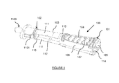
Figure 1 illustrates a perspective view of the catheter grip of an embodiment of the invention, including a tip insert. -
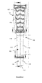
Figure 2 illustrates a plan view of the catheter grip ofFigure 1 , excluding the tip insert. -
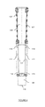
Figures 3A and 3B illustrate plan views of alternative embodiments of the catheter grip of the invention. -
Figure 4 illustrates a side view of the catheter grip ofFigure 1 . -
Figure 5 illustrates a sectional view (Section L-L) of the catheter grip ofFigure 1 . -
Figure 6 illustrates a sectional view (Section J-J) of the catheter grip ofFigure 1 . -
Figure 7 illustrates a sectional view (Section M-M) of the catheter grip ofFigure 1 . -
Figure 8 illustrates an end view of the catheter grip ofFigure 1 . -
Figure 9 illustrates the catheter grip ofFigure 1 on a catheter shaft. -
Figure 10 illustrates the catheter grip ofFigure 1 on a catheter shaft in a flexed position. -
Figure 11 illustrates a tip insert. -
Figure 12 illustrates a perspective view of the catheter grip of an alternative embodiment of the invention. - The present invention provides a catheter assembly and catheter grip. In particular, the invention relates to catheters provided with a resiliently biased grip that assists with insertion of the catheter.
- Hereinafter, this specification will describe the present invention according to the preferred embodiments. It is to be understood that limiting the description to the preferred embodiments of the invention is merely to facilitate discussion of the present invention and it is envisioned without departing from the scope of the appended claims.
- Referring to
Figures 1 to 8 , acatheter grip 100 is provided. Thecatheter grip 100 includes abody portion 101 and ahead portion 102 that joined through an interposedbiasing mechanism 103. As such, thebody portion 101,head portion 102 andbiasing mechanism 103 are an integral unit. - The
body portion 101 is of a generally frustoconical shape and includes opposed grippingsurfaces 104. The grippingsurfaces 104 are compressible towards one another such that a catheter shaft (not shown) that extends through thepassage 105 defined by thebody member 101 can be indirectly gripped by a user of thecatheter grip 100. Generally, the material forming thegripping surfaces 104 will be thinner than the material forming the remainder of thebody portion 101, thereby giving the grippingsurfaces 104 more flexibility than the remainder of the body portion. - The
body portion 101 includes opposedlongitudinal walls 106 that extend between edges of the opposed grippingsurfaces 104. The material forming thelongitudinal walls 106 is, as discussed above, thicker than that forming thegripping surfaces 104 to provide thelongitudinal walls 106 with greater rigidity and structural strength. The grippingsurfaces 104 are also provided withridges 107 to assist with gripping of the catheter shaft through the gripping surfaces 104. - As illustrated in
Figures 3A and 3B , the dimensions of thebody portion 301 may vary without dramatically affecting the operation of the catheter grip 300. Likewise, the form and dimensions of thecollar 308 forming thehead portion 302 may vary, as may those of thelateral walls 311. A more preferred form of thecatheter grip 100 may be gleaned fromFigure 2 , which includes a relativelynarrow body portion 101,collar 108 and lateral walls 111 (i.e. compared with those of the catheter grips 300 ofFigures 3A and 3B ). - The
head portion 102 includes acollar 108 that defines anaperture 109 through which the catheter shaft extends. Aninsert 1100 may be fitted onto thecollar 108 or inserted into theaperture 109. As discussed in more detail below, theinsert 1100 includes atubular portion 1101 that is complementary with theaperture 109 and which receives or is inserted into thecollar 108. An abutment located on the insert includes an abutment surface that abuts anouter edge 110 of thecollar 108. A catheter feed is also provided on the insert which extend from the abutment, away from thecollar 108 of thehead portion 102. The catheter feed is complementary with the catheter shaft and is generally formed from a thin polymeric material that lightly engages the catheter shaft as it passes there through. In particular, the shaft feed lightly engages the catheter to ensure that the catheter shaft passes through catheter feed without difficulty, but so that the catheter shaft cannot easily retract back through the catheter feed. - The
biasing mechanism 103 includes two opposedlongitudinal walls 111. Thelongitudinal walls 111 are formed from a resilient material, as is the remainder of thecatheter grip 100. Eachlongitudinal wall 111 includes a weakened ordiminished portion 112, in this case grooves that traverse inner surfaces of thelongitudinal walls 111 at or around a longitudinal mid-point thereof. Weakened ordiminished portions 113 may also be provided at either end of thelongitudinal walls 111. - The
lateral walls 111 are disposed in the same plane as the gripping surfaces 104. It has been found that such an arrangement advantageously ensures appropriate outward flexing of thelateral walls 111 in use, as discussed below. However, as discussed hereafter, other arrangements are considered within the ambit of the present invention. A number of longitudinally extendingalignment ribs 114 on inner surfaces of the gripping surfaces 104. Thealignment ribs 114 advantageously maintain the position of the catheter shaft when it is gripped by a user during insertion. That is, lateral movement of the catheter shaft within thecatheter grip 100 is minimised. - In use, as illustrated in
Figures 9 and 10 , a user of thecatheter grip 100 grips acatheter shaft 900 passing through thecatheter grip 100 by compressing the twogripping surfaces 104 towards one another with finger and thumb. Once thecatheter shaft 900 is gripped, the user forces thebody portion 101 towards thehead portion 102 against the bias of thebiasing mechanism 103. The catheter shaft thereby passes through thehead portion 102 andtip insert 1100 and is inserted into the user or patient. In doing so, thelongitudinal walls 111 of thebiasing mechanism 103 flex outwardly until thebody portion 101 approaches or abuts thehead portion 102. The user of thecatheter grip 100 can then release their grip of thegripping surfaces 104, thereby releasing their grip on thecatheter shaft 900. Thebiasing mechanism 103, on release of the user's grip on thecatheter shaft 900, biases thebody portion 101 away from thehead portion 102, while the position of thecatheter shaft 900 relative to thehead portion 102 is maintained due to light engagement of thetip insert 1100 with thecatheter shaft 900, as discussed with reference to Figure 1100. As such, effectively a length of thecatheter shaft 900 corresponding to the length of thelongitudinal walls 111 has been fed through thehead portion 102 and into the user or patient. This process may be repeated until a desired length of thecatheter shaft 900 has been inserted into the user or patient. - A
tip insert 1100 for thecatheter grip 100 is illustrated inFigure 11 . Thetip insert 1100 includes atubular portion 1101 that is generally inserted into theaperture 109 of thecollar 108 of thehead portion 102. Thetip insert 1100 includes anabutment 1102 that provides anabutment surface 1103. On insertion of thetip insert 1100 into thecollar 108, theouter edge 110 of thecollar 108 abuts theabutment surface 1103.Ridges 1104 are provided to ensure frictional engagement of thetip insert 1100 in thecollar 108. Afeed potion 1105 fittingly receives thecatheter shaft 900 and includesflexible tabs 1106 that flare outwardly as thecatheter shaft 900 passed through thefeed portion 1105. Theflexible tabs 1106 facilitate light engagement of thecatheter shaft 900 by thefeed portion 1105 of thetip insert 1100 preventing retraction of thecatheter shaft 900 back into thecatheter grip 100 during feeding of thecatheter shaft 900 through thefeed portion 1105. - Referring to
Figure 12 , an alternative embodiment of acatheter grip 1200 is illustrated. Thecatheter grip 1200 again includes abody portion 1201 and ahead portion 1202 that joined through an interposedbiasing mechanism 1203. Thebody portion 1201 is again of a generally frustoconical shape and includes opposed grippingsurfaces 1204. The grippingsurfaces 1204 are compressible towards one another such that a catheter shaft (not shown) can be indirectly gripped by a user of thecatheter grip 1200. - The
body portion 1201 again includes opposedlongitudinal walls 1206 that extend between edges of the opposed grippingsurfaces 1204.Ridges 1207 are provided to assist with gripping of the catheter shaft through the gripping surfaces 1204. - The
head portion 1202 includes acollar 1208 that defines anaperture 1209 through which the catheter shaft extends. An insert can also be provided, as discussed previously. - The
biasing mechanism 1203 includes two opposedlongitudinal walls 1211 including a weakened ordiminished portion 1212 at or around a longitudinal mid-point thereof and weakened ordiminished portions 1213 at either end of thelongitudinal walls 1211. In this embodiment, thelateral walls 1211 are disposed in a plane that is transverse to that of thegripping surfaces 1204. - The catheter shaft may be lubricated if desired and the form of packaging is also not particularly limited. Generally, it is envisaged that the catheter assembly will be packaged in an elongate package with a tear off or tear open tab facilitating easy access to the catheter assembly with minimal effort.
- Unless the context requires otherwise or specifically stated to the contrary, integers, steps or elements of the invention recited herein as singular integers, steps or elements clearly encompass both singular and plural forms of the recited integers, steps or elements.
- Throughout this specification, unless the context requires otherwise, the word "comprise", or variations such as "comprises" or "comprising", will be understood to imply the inclusion of a stated step or element or integer or group of steps or elements or integers, but not the exclusion of any other step or element or integer or group of steps, elements or integers. Thus, in the context of this specification, the term "comprising" is used in an inclusive sense and thus should be understood as meaning "including principally, but not necessarily solely".
Claims (17)
- A catheter grip for a catheter shaft, said catheter grip comprising:a body portion adapted to extend circumferentially around said catheter shaft to facilitate gripping of said catheter shaft by a user;a head portion through which said catheter shaft can be fed; anda biasing mechanism,
wherein said biasing mechanism biases said body portion and said head portion away from one another. - A catheter grip according to claim 1, wherein said biasing mechanism is disposed between said body portion and said head portion.
- A catheter grip according to claim 1 or 2, wherein said biasing mechanism comprises at least two laterally spaced walls extending between said body portion and said head portion, said laterally spaced walls being resiliently deformable to provide said biasing.
- A catheter grip according to claim 3, wherein each of said laterally spaced walls comprises a weakened or diminished portion at or around a longitudinal mid-point thereof such that, in use, as said body portion is forced towards said head portion said laterally spaced walls flex outwardly to provide said biasing.
- A catheter grip according to claim 4, wherein each of said laterally spaced walls comprises a weakened or diminished portion adjacent the head portion and/or the body portion.
- A catheter grip according to any one of claims 1 to 5, wherein said body portion comprises two opposed gripping surfaces that are resiliently compressible towards one another to facilitate gripping of said catheter shaft by a user.
- A catheter grip according to claim 6, wherein said body portion comprises opposed longitudinal walls that extend between edges of said opposed gripping surfaces.
- A catheter grip according to claim 6 or 7, wherein said biasing mechanism comprises two opposed laterally spaced walls extending between said body portion and said head portion, said laterally spaced walls being resiliently deformable to provide said biasing, and wherein said opposed gripping surfaces are disposed in the same plane as said opposed laterally spaced walls.
- A catheter grip according to any one of claims 1 to 8, wherein said head portion comprises a collar.
- A catheter grip according to claim 9, wherein said head portion additionally comprises a shaft feed extending from said collar through which said catheter shaft is fed.
- A catheter grip according to claim 10, wherein said shaft feed is disposed on a feed insert that is adapted to be inserted into said collar of said head portion.
- A catheter grip according to claim 11, wherein said feed insert comprises a tubular portion having at least one ridge, said tubular portion being received by said collar of said head portion, an abutment having an abutment surface which abuts said collar of said head portion, and said shaft feed which extends from an outer face of said abutment.
- A catheter grip according to any one of claims 1 to 12, wherein said body portion, head portion and biasing mechanism are integral with one another to provide said catheter grip.
- A catheter assembly comprising:a catheter shaft having a drainage outlet at a proximal end thereof and a catheter tip and at least one drainage inlet at a distal end thereof; anda catheter grip associated with said catheter shaft, said catheter grip comprising a body portion that extends circumferentially around said catheter shaft and facilitates gripping of said catheter shaft by a user, and a head portion through which said catheter shaft can be fed,wherein said catheter grip comprises a biasing mechanism that biases said body portion and said head portion away from one another.
- A catheter assembly according to claim 14, wherein said catheter grip is a catheter grip as claimed in any one of claims 1 to 13.
- A catheter assembly according to claim 14 or 15, wherein said drainage outlet comprises a catheter funnel.
- A catheter assembly according to any one of claims 14 to 16, wherein said at least one drainage inlet of said catheter shaft comprises at least one eyelet.
Applications Claiming Priority (1)
| Application Number | Priority Date | Filing Date | Title |
|---|---|---|---|
| AU2012903716A AU2012903716A0 (en) | 2012-08-29 | Catheter assembly and catheter sleeve |
Publications (3)
| Publication Number | Publication Date |
|---|---|
| EP2703036A2 true EP2703036A2 (en) | 2014-03-05 |
| EP2703036A3 EP2703036A3 (en) | 2014-06-11 |
| EP2703036B1 EP2703036B1 (en) | 2020-10-21 |
Family
ID=49035344
Family Applications (1)
| Application Number | Title | Priority Date | Filing Date |
|---|---|---|---|
| EP13181106.9A Active EP2703036B1 (en) | 2012-08-29 | 2013-08-20 | Catheter grip and catheter assembly |
Country Status (4)
| Country | Link |
|---|---|
| US (1) | US9345855B2 (en) |
| EP (1) | EP2703036B1 (en) |
| CN (1) | CN103751899B (en) |
| AU (1) | AU2013219138B2 (en) |
Cited By (6)
| Publication number | Priority date | Publication date | Assignee | Title |
|---|---|---|---|---|
| WO2017053279A1 (en) * | 2015-09-25 | 2017-03-30 | Hollister Incorporated | Applicators for gripping urinary catheters and catheter assemblies including the same |
| EP3613457A1 (en) * | 2018-08-24 | 2020-02-26 | Cure Medical, LLC | Packaged urinary catheter with catheter dispensing system |
| US10980974B2 (en) | 2017-08-08 | 2021-04-20 | Cure Medical Llc | Methods of dispensing a urinary catheter from a sterile package |
| USD918382S1 (en) | 2018-07-26 | 2021-05-04 | Hollister Incorporated | Urinary catheter |
| KR20210111046A (en) * | 2020-03-02 | 2021-09-10 | 전북대학교산학협력단 | Through type Medical suction device |
| US12076506B2 (en) | 2017-08-08 | 2024-09-03 | Convatec Inc | Sterile urinary catheter package with dispensing system |
Families Citing this family (22)
| Publication number | Priority date | Publication date | Assignee | Title |
|---|---|---|---|---|
| AU2009242503B2 (en) | 2008-05-01 | 2014-11-20 | Convatec Technologies Inc. | Rectal drain appliance |
| US10099032B2 (en) | 2010-12-30 | 2018-10-16 | Dentsply Ih Ab | Catheter with integrated insertion aid |
| AU2012313393A1 (en) | 2011-03-17 | 2013-10-31 | Convatec Technologies Inc. | High barrier elastomer fecal catheter or ostomy pouch |
| EP3272383A1 (en) * | 2012-03-05 | 2018-01-24 | Dentsply IH AB | Catheter with partially slitted insertion aid |
| CN105407961A (en) | 2013-08-01 | 2016-03-16 | 康沃特克科技公司 | Self-closing bag connector |
| WO2015142506A1 (en) * | 2014-03-17 | 2015-09-24 | Hollister Incorporated | Intermittent catheters having hydration/gripper devices |
| KR102462510B1 (en) | 2014-08-26 | 2022-11-01 | 씨. 알. 바드, 인크. | Urinary catheter |
| USD784523S1 (en) | 2014-12-10 | 2017-04-18 | Hollister Incorporated | Catheter gripper aid |
| US10179046B2 (en) * | 2015-08-14 | 2019-01-15 | Edwards Lifesciences Corporation | Gripping and pushing device for medical instrument |
| CO2018003987A2 (en) * | 2015-09-16 | 2018-09-20 | Lovasz Sandor | Adapter and process for manufacturing a device for instilling agents in the bladder, through the urethra, without catheter use |
| USD816217S1 (en) | 2016-10-12 | 2018-04-24 | Hollister Incorporated | Urinary catheter |
| WO2019048929A2 (en) * | 2017-09-05 | 2019-03-14 | Bowline Medical Pty Ltd | Catheter and guidewire advancement device |
| US11090462B2 (en) | 2017-09-05 | 2021-08-17 | Andrew DYALL | Advancement or retraction device |
| GB201721956D0 (en) | 2017-12-27 | 2018-02-07 | Convatec Ltd | Female catheter locator tip |
| GB201721955D0 (en) | 2017-12-27 | 2018-02-07 | Convatec Ltd | Catheter wetting devices |
| USD903111S1 (en) | 2018-01-15 | 2020-11-24 | Hollister Incorporated | Catheter gripping aid |
| USD846116S1 (en) | 2018-03-02 | 2019-04-16 | Hollister Incorporated | Urinary catheter |
| USD935016S1 (en) | 2018-06-15 | 2021-11-02 | Hollister Incorporated | Catheter gripping aid |
| EP3755413B1 (en) | 2018-06-19 | 2024-02-14 | Hollister Incorporated | Female urinary catheter deployment devices and methods of using the same |
| BR112021024882A2 (en) | 2019-06-11 | 2022-02-01 | Convatec Technologies Inc | Urine collection bags for use with catheter products, kits incorporating the same and methods for the same |
| US12589218B2 (en) | 2020-08-03 | 2026-03-31 | C. R. Bard, Inc. | Intermittent-catheter assembly and methods thereof |
| CN116322871A (en) | 2020-09-11 | 2023-06-23 | C·R·巴德股份有限公司 | Intermittent catheter assembly and method |
Family Cites Families (27)
| Publication number | Priority date | Publication date | Assignee | Title |
|---|---|---|---|---|
| US3713447A (en) * | 1971-08-16 | 1973-01-30 | E Adair | Suprapubic shunt |
| US4389208A (en) * | 1980-11-06 | 1983-06-21 | Leveen Robert F | Catheter advancer |
| US4627838A (en) * | 1983-12-09 | 1986-12-09 | Bard Limited | Stylet actuated winged catheter |
| US4713057A (en) * | 1984-02-27 | 1987-12-15 | Medical College Of Ohio | Mechanical assist device for inserting catheters |
| US4553961A (en) | 1984-04-18 | 1985-11-19 | Cordis Corporation | Suture sleeve with structure for enhancing pacing lead gripping |
| US4867172A (en) * | 1988-02-23 | 1989-09-19 | Habley Medical Technology Corporation | Collapsible blood collector |
| US5073166A (en) * | 1989-02-15 | 1991-12-17 | Medical Innovations Corporation | Method and apparatus for emplacement of a gastrostomy catheter |
| US5409453A (en) | 1992-08-12 | 1995-04-25 | Vidamed, Inc. | Steerable medical probe with stylets |
| US5242398A (en) * | 1992-03-12 | 1993-09-07 | Knoll Charles L | Catheter assembly and related method |
| US5401257A (en) * | 1993-04-27 | 1995-03-28 | Boston Scientific Corporation | Ureteral stents, drainage tubes and the like |
| US5454798A (en) * | 1993-05-14 | 1995-10-03 | Mentor Corporation | Disposable urine bag |
| US5423784A (en) | 1994-01-11 | 1995-06-13 | Hollister Incorporated | Extended male catheter applicator and methods of use |
| US5643280A (en) * | 1995-12-07 | 1997-07-01 | The Anspach Effort, Inc. | Integral myringotomy tube and inserter |
| IT1318346B1 (en) * | 2000-06-12 | 2003-08-25 | Cgm Spa | PROTECTION DEVICE FOR MEDICAL NEEDLES. |
| US20020103467A1 (en) * | 2001-01-31 | 2002-08-01 | Kubalak Thomas P. | Urine collection bags for urinary catheter systems |
| ES2320205T3 (en) * | 2001-06-29 | 2009-05-20 | Coloplast A/S | A CATETER SET. |
| DE60215297T2 (en) * | 2002-03-18 | 2007-08-30 | William Cook Europe Aps | Medical device for gripping an elongate element |
| AU2003218224A1 (en) | 2002-03-18 | 2003-10-08 | Cook Incorporated | Medical device for gripping an elongated member |
| CA2422516A1 (en) * | 2002-03-19 | 2003-09-19 | Becton, Dickinson And Company | Needle device |
| US7819841B2 (en) | 2004-08-18 | 2010-10-26 | Medtronic Vascular, Inc. | Vessel isolation device |
| CA2597398A1 (en) * | 2005-02-14 | 2006-08-17 | Flexicath Ltd. | Method and apparatus for inserting a catheter device |
| US8613728B2 (en) * | 2005-11-07 | 2013-12-24 | Flexicath Ltd. | Removable adapter for a splittable introducer and method of use thereof |
| US8101091B2 (en) | 2006-10-02 | 2012-01-24 | Greatbatch Ltd. | Introducer assembly and method for forming an introducer assembly |
| US7985217B2 (en) | 2006-10-24 | 2011-07-26 | Medical Technologies Of Georgia, Inc. | Catheter movement system |
| US20100286664A1 (en) * | 2009-05-08 | 2010-11-11 | Abbott Cardiovascular Systems, Inc. | Catheter push device |
| US8728057B2 (en) | 2009-06-04 | 2014-05-20 | Adapta Medical, Inc. | Devices and methods for catheter advancement |
| JP4608603B1 (en) * | 2009-12-18 | 2011-01-12 | 株式会社ユニシス | Medical needle |
-
2013
- 2013-08-19 AU AU2013219138A patent/AU2013219138B2/en not_active Ceased
- 2013-08-20 EP EP13181106.9A patent/EP2703036B1/en active Active
- 2013-08-28 US US14/012,741 patent/US9345855B2/en active Active
- 2013-08-29 CN CN201310384937.9A patent/CN103751899B/en active Active
Non-Patent Citations (1)
| Title |
|---|
| None |
Cited By (7)
| Publication number | Priority date | Publication date | Assignee | Title |
|---|---|---|---|---|
| WO2017053279A1 (en) * | 2015-09-25 | 2017-03-30 | Hollister Incorporated | Applicators for gripping urinary catheters and catheter assemblies including the same |
| US10980974B2 (en) | 2017-08-08 | 2021-04-20 | Cure Medical Llc | Methods of dispensing a urinary catheter from a sterile package |
| US12076506B2 (en) | 2017-08-08 | 2024-09-03 | Convatec Inc | Sterile urinary catheter package with dispensing system |
| USD918382S1 (en) | 2018-07-26 | 2021-05-04 | Hollister Incorporated | Urinary catheter |
| USD1111162S1 (en) | 2018-07-26 | 2026-02-03 | Hollister Incorporated | Urinary catheter |
| EP3613457A1 (en) * | 2018-08-24 | 2020-02-26 | Cure Medical, LLC | Packaged urinary catheter with catheter dispensing system |
| KR20210111046A (en) * | 2020-03-02 | 2021-09-10 | 전북대학교산학협력단 | Through type Medical suction device |
Also Published As
| Publication number | Publication date |
|---|---|
| EP2703036A3 (en) | 2014-06-11 |
| CN103751899A (en) | 2014-04-30 |
| AU2013219138B2 (en) | 2017-02-16 |
| CN103751899B (en) | 2018-02-13 |
| US9345855B2 (en) | 2016-05-24 |
| EP2703036B1 (en) | 2020-10-21 |
| US20140066905A1 (en) | 2014-03-06 |
| AU2013219138A1 (en) | 2014-03-20 |
Similar Documents
| Publication | Publication Date | Title |
|---|---|---|
| EP2703036B1 (en) | Catheter grip and catheter assembly | |
| AU2012101310A4 (en) | A packaged catheter assembly | |
| EP2459264B1 (en) | Catheter having improved drainage | |
| US10639451B2 (en) | Applicators for gripping urinary catheters and catheter assemblies including the same | |
| GB1590747A (en) | Urinary retention catheter | |
| US9950138B2 (en) | Indwelling urinary catheter | |
| US10279145B2 (en) | Catheter placement assist device and method of use | |
| JP2023502328A (en) | actively deflectable urinary catheter | |
| JP2022554057A (en) | Urinary catheter and method of catheterizing the bladder using an actively deflectable urinary catheter and deflection mechanism | |
| US20250058081A1 (en) | Urinary Placement Catheter for Intravesical Devices | |
| US20250303110A1 (en) | Catheter Clearing System and Methods | |
| AU2024263066A1 (en) | Urinary catheter assembly with guidance device | |
| HK1169621B (en) | Catheter having improved drainage |
Legal Events
| Date | Code | Title | Description |
|---|---|---|---|
| AK | Designated contracting states |
Kind code of ref document: A2 Designated state(s): AL AT BE BG CH CY CZ DE DK EE ES FI FR GB GR HR HU IE IS IT LI LT LU LV MC MK MT NL NO PL PT RO RS SE SI SK SM TR |
|
| AX | Request for extension of the european patent |
Extension state: BA ME |
|
| PUAI | Public reference made under article 153(3) epc to a published international application that has entered the european phase |
Free format text: ORIGINAL CODE: 0009012 |
|
| PUAL | Search report despatched |
Free format text: ORIGINAL CODE: 0009013 |
|
| AK | Designated contracting states |
Kind code of ref document: A3 Designated state(s): AL AT BE BG CH CY CZ DE DK EE ES FI FR GB GR HR HU IE IS IT LI LT LU LV MC MK MT NL NO PL PT RO RS SE SI SK SM TR |
|
| AX | Request for extension of the european patent |
Extension state: BA ME |
|
| RIC1 | Information provided on ipc code assigned before grant |
Ipc: A61M 25/01 20060101AFI20140507BHEP |
|
| 17P | Request for examination filed |
Effective date: 20141210 |
|
| RBV | Designated contracting states (corrected) |
Designated state(s): AL AT BE BG CH CY CZ DE DK EE ES FI FR GB GR HR HU IE IS IT LI LT LU LV MC MK MT NL NO PL PT RO RS SE SI SK SM TR |
|
| STAA | Information on the status of an ep patent application or granted ep patent |
Free format text: STATUS: EXAMINATION IS IN PROGRESS |
|
| 17Q | First examination report despatched |
Effective date: 20170306 |
|
| REG | Reference to a national code |
Ref country code: DE Ref legal event code: R079 Ref document number: 602013073407 Country of ref document: DE Free format text: PREVIOUS MAIN CLASS: A61M0025010000 Ipc: A61M0025000000 |
|
| GRAP | Despatch of communication of intention to grant a patent |
Free format text: ORIGINAL CODE: EPIDOSNIGR1 |
|
| STAA | Information on the status of an ep patent application or granted ep patent |
Free format text: STATUS: GRANT OF PATENT IS INTENDED |
|
| RIC1 | Information provided on ipc code assigned before grant |
Ipc: A61M 25/01 20060101ALI20190607BHEP Ipc: A61M 25/09 20060101ALI20190607BHEP Ipc: A61M 25/00 20060101AFI20190607BHEP Ipc: A61F 2/95 20130101ALI20190607BHEP |
|
| INTG | Intention to grant announced |
Effective date: 20190704 |
|
| GRAJ | Information related to disapproval of communication of intention to grant by the applicant or resumption of examination proceedings by the epo deleted |
Free format text: ORIGINAL CODE: EPIDOSDIGR1 |
|
| STAA | Information on the status of an ep patent application or granted ep patent |
Free format text: STATUS: EXAMINATION IS IN PROGRESS |
|
| INTC | Intention to grant announced (deleted) | ||
| GRAP | Despatch of communication of intention to grant a patent |
Free format text: ORIGINAL CODE: EPIDOSNIGR1 |
|
| STAA | Information on the status of an ep patent application or granted ep patent |
Free format text: STATUS: GRANT OF PATENT IS INTENDED |
|
| INTG | Intention to grant announced |
Effective date: 20200608 |
|
| GRAS | Grant fee paid |
Free format text: ORIGINAL CODE: EPIDOSNIGR3 |
|
| GRAA | (expected) grant |
Free format text: ORIGINAL CODE: 0009210 |
|
| STAA | Information on the status of an ep patent application or granted ep patent |
Free format text: STATUS: THE PATENT HAS BEEN GRANTED |
|
| AK | Designated contracting states |
Kind code of ref document: B1 Designated state(s): AL AT BE BG CH CY CZ DE DK EE ES FI FR GB GR HR HU IE IS IT LI LT LU LV MC MK MT NL NO PL PT RO RS SE SI SK SM TR |
|
| REG | Reference to a national code |
Ref country code: GB Ref legal event code: FG4D |
|
| REG | Reference to a national code |
Ref country code: CH Ref legal event code: EP |
|
| REG | Reference to a national code |
Ref country code: DE Ref legal event code: R096 Ref document number: 602013073407 Country of ref document: DE |
|
| REG | Reference to a national code |
Ref country code: IE Ref legal event code: FG4D |
|
| REG | Reference to a national code |
Ref country code: AT Ref legal event code: REF Ref document number: 1325217 Country of ref document: AT Kind code of ref document: T Effective date: 20201115 |
|
| REG | Reference to a national code |
Ref country code: AT Ref legal event code: MK05 Ref document number: 1325217 Country of ref document: AT Kind code of ref document: T Effective date: 20201021 |
|
| REG | Reference to a national code |
Ref country code: NL Ref legal event code: MP Effective date: 20201021 |
|
| PG25 | Lapsed in a contracting state [announced via postgrant information from national office to epo] |
Ref country code: FI Free format text: LAPSE BECAUSE OF FAILURE TO SUBMIT A TRANSLATION OF THE DESCRIPTION OR TO PAY THE FEE WITHIN THE PRESCRIBED TIME-LIMIT Effective date: 20201021 Ref country code: RS Free format text: LAPSE BECAUSE OF FAILURE TO SUBMIT A TRANSLATION OF THE DESCRIPTION OR TO PAY THE FEE WITHIN THE PRESCRIBED TIME-LIMIT Effective date: 20201021 Ref country code: NO Free format text: LAPSE BECAUSE OF FAILURE TO SUBMIT A TRANSLATION OF THE DESCRIPTION OR TO PAY THE FEE WITHIN THE PRESCRIBED TIME-LIMIT Effective date: 20210121 Ref country code: PT Free format text: LAPSE BECAUSE OF FAILURE TO SUBMIT A TRANSLATION OF THE DESCRIPTION OR TO PAY THE FEE WITHIN THE PRESCRIBED TIME-LIMIT Effective date: 20210222 Ref country code: NL Free format text: LAPSE BECAUSE OF FAILURE TO SUBMIT A TRANSLATION OF THE DESCRIPTION OR TO PAY THE FEE WITHIN THE PRESCRIBED TIME-LIMIT Effective date: 20201021 Ref country code: GR Free format text: LAPSE BECAUSE OF FAILURE TO SUBMIT A TRANSLATION OF THE DESCRIPTION OR TO PAY THE FEE WITHIN THE PRESCRIBED TIME-LIMIT Effective date: 20210122 |
|
| REG | Reference to a national code |
Ref country code: LT Ref legal event code: MG4D |
|
| PG25 | Lapsed in a contracting state [announced via postgrant information from national office to epo] |
Ref country code: IS Free format text: LAPSE BECAUSE OF FAILURE TO SUBMIT A TRANSLATION OF THE DESCRIPTION OR TO PAY THE FEE WITHIN THE PRESCRIBED TIME-LIMIT Effective date: 20210221 Ref country code: PL Free format text: LAPSE BECAUSE OF FAILURE TO SUBMIT A TRANSLATION OF THE DESCRIPTION OR TO PAY THE FEE WITHIN THE PRESCRIBED TIME-LIMIT Effective date: 20201021 Ref country code: SE Free format text: LAPSE BECAUSE OF FAILURE TO SUBMIT A TRANSLATION OF THE DESCRIPTION OR TO PAY THE FEE WITHIN THE PRESCRIBED TIME-LIMIT Effective date: 20201021 Ref country code: LV Free format text: LAPSE BECAUSE OF FAILURE TO SUBMIT A TRANSLATION OF THE DESCRIPTION OR TO PAY THE FEE WITHIN THE PRESCRIBED TIME-LIMIT Effective date: 20201021 Ref country code: BG Free format text: LAPSE BECAUSE OF FAILURE TO SUBMIT A TRANSLATION OF THE DESCRIPTION OR TO PAY THE FEE WITHIN THE PRESCRIBED TIME-LIMIT Effective date: 20210121 Ref country code: ES Free format text: LAPSE BECAUSE OF FAILURE TO SUBMIT A TRANSLATION OF THE DESCRIPTION OR TO PAY THE FEE WITHIN THE PRESCRIBED TIME-LIMIT Effective date: 20201021 Ref country code: AT Free format text: LAPSE BECAUSE OF FAILURE TO SUBMIT A TRANSLATION OF THE DESCRIPTION OR TO PAY THE FEE WITHIN THE PRESCRIBED TIME-LIMIT Effective date: 20201021 |
|
| PG25 | Lapsed in a contracting state [announced via postgrant information from national office to epo] |
Ref country code: HR Free format text: LAPSE BECAUSE OF FAILURE TO SUBMIT A TRANSLATION OF THE DESCRIPTION OR TO PAY THE FEE WITHIN THE PRESCRIBED TIME-LIMIT Effective date: 20201021 |
|
| REG | Reference to a national code |
Ref country code: DE Ref legal event code: R097 Ref document number: 602013073407 Country of ref document: DE |
|
| PG25 | Lapsed in a contracting state [announced via postgrant information from national office to epo] |
Ref country code: SM Free format text: LAPSE BECAUSE OF FAILURE TO SUBMIT A TRANSLATION OF THE DESCRIPTION OR TO PAY THE FEE WITHIN THE PRESCRIBED TIME-LIMIT Effective date: 20201021 Ref country code: CZ Free format text: LAPSE BECAUSE OF FAILURE TO SUBMIT A TRANSLATION OF THE DESCRIPTION OR TO PAY THE FEE WITHIN THE PRESCRIBED TIME-LIMIT Effective date: 20201021 Ref country code: EE Free format text: LAPSE BECAUSE OF FAILURE TO SUBMIT A TRANSLATION OF THE DESCRIPTION OR TO PAY THE FEE WITHIN THE PRESCRIBED TIME-LIMIT Effective date: 20201021 Ref country code: RO Free format text: LAPSE BECAUSE OF FAILURE TO SUBMIT A TRANSLATION OF THE DESCRIPTION OR TO PAY THE FEE WITHIN THE PRESCRIBED TIME-LIMIT Effective date: 20201021 Ref country code: SK Free format text: LAPSE BECAUSE OF FAILURE TO SUBMIT A TRANSLATION OF THE DESCRIPTION OR TO PAY THE FEE WITHIN THE PRESCRIBED TIME-LIMIT Effective date: 20201021 Ref country code: LT Free format text: LAPSE BECAUSE OF FAILURE TO SUBMIT A TRANSLATION OF THE DESCRIPTION OR TO PAY THE FEE WITHIN THE PRESCRIBED TIME-LIMIT Effective date: 20201021 |
|
| PLBE | No opposition filed within time limit |
Free format text: ORIGINAL CODE: 0009261 |
|
| STAA | Information on the status of an ep patent application or granted ep patent |
Free format text: STATUS: NO OPPOSITION FILED WITHIN TIME LIMIT |
|
| PG25 | Lapsed in a contracting state [announced via postgrant information from national office to epo] |
Ref country code: DK Free format text: LAPSE BECAUSE OF FAILURE TO SUBMIT A TRANSLATION OF THE DESCRIPTION OR TO PAY THE FEE WITHIN THE PRESCRIBED TIME-LIMIT Effective date: 20201021 |
|
| 26N | No opposition filed |
Effective date: 20210722 |
|
| PG25 | Lapsed in a contracting state [announced via postgrant information from national office to epo] |
Ref country code: IT Free format text: LAPSE BECAUSE OF FAILURE TO SUBMIT A TRANSLATION OF THE DESCRIPTION OR TO PAY THE FEE WITHIN THE PRESCRIBED TIME-LIMIT Effective date: 20201021 Ref country code: AL Free format text: LAPSE BECAUSE OF FAILURE TO SUBMIT A TRANSLATION OF THE DESCRIPTION OR TO PAY THE FEE WITHIN THE PRESCRIBED TIME-LIMIT Effective date: 20201021 |
|
| PG25 | Lapsed in a contracting state [announced via postgrant information from national office to epo] |
Ref country code: SI Free format text: LAPSE BECAUSE OF FAILURE TO SUBMIT A TRANSLATION OF THE DESCRIPTION OR TO PAY THE FEE WITHIN THE PRESCRIBED TIME-LIMIT Effective date: 20201021 |
|
| PG25 | Lapsed in a contracting state [announced via postgrant information from national office to epo] |
Ref country code: MC Free format text: LAPSE BECAUSE OF FAILURE TO SUBMIT A TRANSLATION OF THE DESCRIPTION OR TO PAY THE FEE WITHIN THE PRESCRIBED TIME-LIMIT Effective date: 20201021 |
|
| REG | Reference to a national code |
Ref country code: BE Ref legal event code: MM Effective date: 20210831 |
|
| PG25 | Lapsed in a contracting state [announced via postgrant information from national office to epo] |
Ref country code: IS Free format text: LAPSE BECAUSE OF FAILURE TO SUBMIT A TRANSLATION OF THE DESCRIPTION OR TO PAY THE FEE WITHIN THE PRESCRIBED TIME-LIMIT Effective date: 20210221 Ref country code: LU Free format text: LAPSE BECAUSE OF NON-PAYMENT OF DUE FEES Effective date: 20210820 |
|
| PG25 | Lapsed in a contracting state [announced via postgrant information from national office to epo] |
Ref country code: BE Free format text: LAPSE BECAUSE OF NON-PAYMENT OF DUE FEES Effective date: 20210831 |
|
| PG25 | Lapsed in a contracting state [announced via postgrant information from national office to epo] |
Ref country code: HU Free format text: LAPSE BECAUSE OF FAILURE TO SUBMIT A TRANSLATION OF THE DESCRIPTION OR TO PAY THE FEE WITHIN THE PRESCRIBED TIME-LIMIT; INVALID AB INITIO Effective date: 20130820 |
|
| PG25 | Lapsed in a contracting state [announced via postgrant information from national office to epo] |
Ref country code: CY Free format text: LAPSE BECAUSE OF FAILURE TO SUBMIT A TRANSLATION OF THE DESCRIPTION OR TO PAY THE FEE WITHIN THE PRESCRIBED TIME-LIMIT Effective date: 20201021 |
|
| PG25 | Lapsed in a contracting state [announced via postgrant information from national office to epo] |
Ref country code: MK Free format text: LAPSE BECAUSE OF FAILURE TO SUBMIT A TRANSLATION OF THE DESCRIPTION OR TO PAY THE FEE WITHIN THE PRESCRIBED TIME-LIMIT Effective date: 20201021 |
|
| PG25 | Lapsed in a contracting state [announced via postgrant information from national office to epo] |
Ref country code: TR Free format text: LAPSE BECAUSE OF FAILURE TO SUBMIT A TRANSLATION OF THE DESCRIPTION OR TO PAY THE FEE WITHIN THE PRESCRIBED TIME-LIMIT Effective date: 20201021 |
|
| PG25 | Lapsed in a contracting state [announced via postgrant information from national office to epo] |
Ref country code: MT Free format text: LAPSE BECAUSE OF FAILURE TO SUBMIT A TRANSLATION OF THE DESCRIPTION OR TO PAY THE FEE WITHIN THE PRESCRIBED TIME-LIMIT Effective date: 20201021 |
|
| PGFP | Annual fee paid to national office [announced via postgrant information from national office to epo] |
Ref country code: DE Payment date: 20250901 Year of fee payment: 13 |
|
| PGFP | Annual fee paid to national office [announced via postgrant information from national office to epo] |
Ref country code: GB Payment date: 20250901 Year of fee payment: 13 |
|
| PGFP | Annual fee paid to national office [announced via postgrant information from national office to epo] |
Ref country code: FR Payment date: 20250901 Year of fee payment: 13 |
|
| PGFP | Annual fee paid to national office [announced via postgrant information from national office to epo] |
Ref country code: CH Payment date: 20250908 Year of fee payment: 13 |
|
| PGFP | Annual fee paid to national office [announced via postgrant information from national office to epo] |
Ref country code: IE Payment date: 20250901 Year of fee payment: 13 |