EP2702941A1 - Ventilator synchronization indicator - Google Patents
Ventilator synchronization indicator Download PDFInfo
- Publication number
- EP2702941A1 EP2702941A1 EP13179682.3A EP13179682A EP2702941A1 EP 2702941 A1 EP2702941 A1 EP 2702941A1 EP 13179682 A EP13179682 A EP 13179682A EP 2702941 A1 EP2702941 A1 EP 2702941A1
- Authority
- EP
- European Patent Office
- Prior art keywords
- breath
- ventilator
- phase angle
- input
- patient
- Prior art date
- Legal status (The legal status is an assumption and is not a legal conclusion. Google has not performed a legal analysis and makes no representation as to the accuracy of the status listed.)
- Granted
Links
Images


Classifications
-
- A—HUMAN NECESSITIES
- A61—MEDICAL OR VETERINARY SCIENCE; HYGIENE
- A61M—DEVICES FOR INTRODUCING MEDIA INTO, OR ONTO, THE BODY; DEVICES FOR TRANSDUCING BODY MEDIA OR FOR TAKING MEDIA FROM THE BODY; DEVICES FOR PRODUCING OR ENDING SLEEP OR STUPOR
- A61M16/00—Devices for influencing the respiratory system of patients by gas treatment, e.g. ventilators; Tracheal tubes
- A61M16/10—Preparation of respiratory gases or vapours
- A61M16/12—Preparation of respiratory gases or vapours by mixing different gases
-
- A—HUMAN NECESSITIES
- A61—MEDICAL OR VETERINARY SCIENCE; HYGIENE
- A61M—DEVICES FOR INTRODUCING MEDIA INTO, OR ONTO, THE BODY; DEVICES FOR TRANSDUCING BODY MEDIA OR FOR TAKING MEDIA FROM THE BODY; DEVICES FOR PRODUCING OR ENDING SLEEP OR STUPOR
- A61M16/00—Devices for influencing the respiratory system of patients by gas treatment, e.g. ventilators; Tracheal tubes
- A61M16/0051—Devices for influencing the respiratory system of patients by gas treatment, e.g. ventilators; Tracheal tubes with alarm devices
-
- A—HUMAN NECESSITIES
- A61—MEDICAL OR VETERINARY SCIENCE; HYGIENE
- A61M—DEVICES FOR INTRODUCING MEDIA INTO, OR ONTO, THE BODY; DEVICES FOR TRANSDUCING BODY MEDIA OR FOR TAKING MEDIA FROM THE BODY; DEVICES FOR PRODUCING OR ENDING SLEEP OR STUPOR
- A61M16/00—Devices for influencing the respiratory system of patients by gas treatment, e.g. ventilators; Tracheal tubes
- A61M16/021—Devices for influencing the respiratory system of patients by gas treatment, e.g. ventilators; Tracheal tubes operated by electrical means
- A61M16/022—Control means therefor
- A61M16/024—Control means therefor including calculation means, e.g. using a processor
-
- A—HUMAN NECESSITIES
- A61—MEDICAL OR VETERINARY SCIENCE; HYGIENE
- A61B—DIAGNOSIS; SURGERY; IDENTIFICATION
- A61B2562/00—Details of sensors; Constructional details of sensor housings or probes; Accessories for sensors
- A61B2562/02—Details of sensors specially adapted for in-vivo measurements
- A61B2562/0247—Pressure sensors
-
- A—HUMAN NECESSITIES
- A61—MEDICAL OR VETERINARY SCIENCE; HYGIENE
- A61B—DIAGNOSIS; SURGERY; IDENTIFICATION
- A61B5/00—Measuring for diagnostic purposes; Identification of persons
- A61B5/08—Measuring devices for evaluating the respiratory organs
- A61B5/087—Measuring breath flow
-
- A—HUMAN NECESSITIES
- A61—MEDICAL OR VETERINARY SCIENCE; HYGIENE
- A61M—DEVICES FOR INTRODUCING MEDIA INTO, OR ONTO, THE BODY; DEVICES FOR TRANSDUCING BODY MEDIA OR FOR TAKING MEDIA FROM THE BODY; DEVICES FOR PRODUCING OR ENDING SLEEP OR STUPOR
- A61M16/00—Devices for influencing the respiratory system of patients by gas treatment, e.g. ventilators; Tracheal tubes
- A61M16/08—Bellows; Connecting tubes ; Water traps; Patient circuits
- A61M16/0808—Condensation traps
-
- A—HUMAN NECESSITIES
- A61—MEDICAL OR VETERINARY SCIENCE; HYGIENE
- A61M—DEVICES FOR INTRODUCING MEDIA INTO, OR ONTO, THE BODY; DEVICES FOR TRANSDUCING BODY MEDIA OR FOR TAKING MEDIA FROM THE BODY; DEVICES FOR PRODUCING OR ENDING SLEEP OR STUPOR
- A61M16/00—Devices for influencing the respiratory system of patients by gas treatment, e.g. ventilators; Tracheal tubes
- A61M16/08—Bellows; Connecting tubes ; Water traps; Patient circuits
- A61M16/0816—Joints or connectors
- A61M16/0833—T- or Y-type connectors, e.g. Y-piece
-
- A—HUMAN NECESSITIES
- A61—MEDICAL OR VETERINARY SCIENCE; HYGIENE
- A61M—DEVICES FOR INTRODUCING MEDIA INTO, OR ONTO, THE BODY; DEVICES FOR TRANSDUCING BODY MEDIA OR FOR TAKING MEDIA FROM THE BODY; DEVICES FOR PRODUCING OR ENDING SLEEP OR STUPOR
- A61M16/00—Devices for influencing the respiratory system of patients by gas treatment, e.g. ventilators; Tracheal tubes
- A61M16/08—Bellows; Connecting tubes ; Water traps; Patient circuits
- A61M16/0866—Passive resistors therefor
-
- A—HUMAN NECESSITIES
- A61—MEDICAL OR VETERINARY SCIENCE; HYGIENE
- A61M—DEVICES FOR INTRODUCING MEDIA INTO, OR ONTO, THE BODY; DEVICES FOR TRANSDUCING BODY MEDIA OR FOR TAKING MEDIA FROM THE BODY; DEVICES FOR PRODUCING OR ENDING SLEEP OR STUPOR
- A61M16/00—Devices for influencing the respiratory system of patients by gas treatment, e.g. ventilators; Tracheal tubes
- A61M16/10—Preparation of respiratory gases or vapours
- A61M16/14—Preparation of respiratory gases or vapours by mixing different fluids, one of them being in a liquid phase
- A61M16/16—Devices to humidify the respiration air
-
- A—HUMAN NECESSITIES
- A61—MEDICAL OR VETERINARY SCIENCE; HYGIENE
- A61M—DEVICES FOR INTRODUCING MEDIA INTO, OR ONTO, THE BODY; DEVICES FOR TRANSDUCING BODY MEDIA OR FOR TAKING MEDIA FROM THE BODY; DEVICES FOR PRODUCING OR ENDING SLEEP OR STUPOR
- A61M16/00—Devices for influencing the respiratory system of patients by gas treatment, e.g. ventilators; Tracheal tubes
- A61M16/22—Carbon dioxide-absorbing devices ; Other means for removing carbon dioxide
-
- A—HUMAN NECESSITIES
- A61—MEDICAL OR VETERINARY SCIENCE; HYGIENE
- A61M—DEVICES FOR INTRODUCING MEDIA INTO, OR ONTO, THE BODY; DEVICES FOR TRANSDUCING BODY MEDIA OR FOR TAKING MEDIA FROM THE BODY; DEVICES FOR PRODUCING OR ENDING SLEEP OR STUPOR
- A61M16/00—Devices for influencing the respiratory system of patients by gas treatment, e.g. ventilators; Tracheal tubes
- A61M16/0003—Accessories therefor, e.g. sensors, vibrators, negative pressure
- A61M2016/0015—Accessories therefor, e.g. sensors, vibrators, negative pressure inhalation detectors
-
- A—HUMAN NECESSITIES
- A61—MEDICAL OR VETERINARY SCIENCE; HYGIENE
- A61M—DEVICES FOR INTRODUCING MEDIA INTO, OR ONTO, THE BODY; DEVICES FOR TRANSDUCING BODY MEDIA OR FOR TAKING MEDIA FROM THE BODY; DEVICES FOR PRODUCING OR ENDING SLEEP OR STUPOR
- A61M16/00—Devices for influencing the respiratory system of patients by gas treatment, e.g. ventilators; Tracheal tubes
- A61M16/0003—Accessories therefor, e.g. sensors, vibrators, negative pressure
- A61M2016/0027—Accessories therefor, e.g. sensors, vibrators, negative pressure pressure meter
-
- A—HUMAN NECESSITIES
- A61—MEDICAL OR VETERINARY SCIENCE; HYGIENE
- A61M—DEVICES FOR INTRODUCING MEDIA INTO, OR ONTO, THE BODY; DEVICES FOR TRANSDUCING BODY MEDIA OR FOR TAKING MEDIA FROM THE BODY; DEVICES FOR PRODUCING OR ENDING SLEEP OR STUPOR
- A61M16/00—Devices for influencing the respiratory system of patients by gas treatment, e.g. ventilators; Tracheal tubes
- A61M16/0003—Accessories therefor, e.g. sensors, vibrators, negative pressure
- A61M2016/003—Accessories therefor, e.g. sensors, vibrators, negative pressure with a flowmeter
- A61M2016/0033—Accessories therefor, e.g. sensors, vibrators, negative pressure with a flowmeter electrical
- A61M2016/0036—Accessories therefor, e.g. sensors, vibrators, negative pressure with a flowmeter electrical in the breathing tube and used in both inspiratory and expiratory phase
-
- A—HUMAN NECESSITIES
- A61—MEDICAL OR VETERINARY SCIENCE; HYGIENE
- A61M—DEVICES FOR INTRODUCING MEDIA INTO, OR ONTO, THE BODY; DEVICES FOR TRANSDUCING BODY MEDIA OR FOR TAKING MEDIA FROM THE BODY; DEVICES FOR PRODUCING OR ENDING SLEEP OR STUPOR
- A61M16/00—Devices for influencing the respiratory system of patients by gas treatment, e.g. ventilators; Tracheal tubes
- A61M16/10—Preparation of respiratory gases or vapours
- A61M16/1005—Preparation of respiratory gases or vapours with O2 features or with parameter measurement
- A61M2016/102—Measuring a parameter of the content of the delivered gas
- A61M2016/1025—Measuring a parameter of the content of the delivered gas the O2 concentration
-
- A—HUMAN NECESSITIES
- A61—MEDICAL OR VETERINARY SCIENCE; HYGIENE
- A61M—DEVICES FOR INTRODUCING MEDIA INTO, OR ONTO, THE BODY; DEVICES FOR TRANSDUCING BODY MEDIA OR FOR TAKING MEDIA FROM THE BODY; DEVICES FOR PRODUCING OR ENDING SLEEP OR STUPOR
- A61M2202/00—Special media to be introduced, removed or treated
- A61M2202/02—Gases
- A61M2202/0208—Oxygen
-
- A—HUMAN NECESSITIES
- A61—MEDICAL OR VETERINARY SCIENCE; HYGIENE
- A61M—DEVICES FOR INTRODUCING MEDIA INTO, OR ONTO, THE BODY; DEVICES FOR TRANSDUCING BODY MEDIA OR FOR TAKING MEDIA FROM THE BODY; DEVICES FOR PRODUCING OR ENDING SLEEP OR STUPOR
- A61M2205/00—General characteristics of the apparatus
- A61M2205/33—Controlling, regulating or measuring
- A61M2205/3331—Pressure; Flow
-
- A—HUMAN NECESSITIES
- A61—MEDICAL OR VETERINARY SCIENCE; HYGIENE
- A61M—DEVICES FOR INTRODUCING MEDIA INTO, OR ONTO, THE BODY; DEVICES FOR TRANSDUCING BODY MEDIA OR FOR TAKING MEDIA FROM THE BODY; DEVICES FOR PRODUCING OR ENDING SLEEP OR STUPOR
- A61M2205/00—General characteristics of the apparatus
- A61M2205/50—General characteristics of the apparatus with microprocessors or computers
- A61M2205/502—User interfaces, e.g. screens or keyboards
-
- A—HUMAN NECESSITIES
- A61—MEDICAL OR VETERINARY SCIENCE; HYGIENE
- A61M—DEVICES FOR INTRODUCING MEDIA INTO, OR ONTO, THE BODY; DEVICES FOR TRANSDUCING BODY MEDIA OR FOR TAKING MEDIA FROM THE BODY; DEVICES FOR PRODUCING OR ENDING SLEEP OR STUPOR
- A61M2205/00—General characteristics of the apparatus
- A61M2205/50—General characteristics of the apparatus with microprocessors or computers
- A61M2205/52—General characteristics of the apparatus with microprocessors or computers with memories providing a history of measured variating parameters of apparatus or patient
-
- A—HUMAN NECESSITIES
- A61—MEDICAL OR VETERINARY SCIENCE; HYGIENE
- A61M—DEVICES FOR INTRODUCING MEDIA INTO, OR ONTO, THE BODY; DEVICES FOR TRANSDUCING BODY MEDIA OR FOR TAKING MEDIA FROM THE BODY; DEVICES FOR PRODUCING OR ENDING SLEEP OR STUPOR
- A61M2205/00—General characteristics of the apparatus
- A61M2205/80—General characteristics of the apparatus voice-operated command
Definitions
- Ventilators are machines used to assist or replace spontaneous breathing of a patient.
- a ventilator may also be used to supply anesthetic agents to the patient undergoing certain medical procedures.
- monitoring patient breathing and ventilator performance may be difficult.
- a caretaker may not easily determine whether a patient is struggling to breathe, whether a patient is fighting the assistance of the ventilator or whether the ventilator is optimally operating to assist the patient with his or her breathing.
- an apparatus comprising: a display; and a processing unit to receive a first input based on airflow in a ventilator for a breath and a second input based upon ventilator firing for the breath, wherein the processing unit is configured to determine a phase angle based on a relationship between the first input and the second input and to provide an indication on the display of a nature of dis-synchrony of airflow and ventilator firing based on the phase angle.
- FIG. 1 schematically illustrates an example of a mechanical ventilation system 10.
- Ventilation system 10 provides a pneumatic circuit that carries breathing gas to and exhaled air from a patient 13 to assist patient 13 in breathing.
- ventilation system 10 provides a graphic that allows a caretaker to more quickly and easily monitor patient breathing and ventilator performance.
- Ventilation system 10 enables a caretaker to more easily determine whether a patient is struggling to breathe, whether a patient is fighting the assistance of the ventilator or whether the ventilators optimally operating to assist the patient with his or her breathing.
- Ventilation system 10 comprises ventilator 12, breathing circuit 14, sensor 16 and display and control unit 18.
- Ventilator 12 supplies gas, such as air or air including anesthetics, drugs or the like, to patient 13 through breathing circuit 14 and receives exhaled air through breathing circuit 14.
- ventilator 12 receives air from air source 20 through conduit 22 and receives oxygen (O 2 ) from an oxygen source 24 (such as a container of compressed oxygen) through conduit 26.
- Ventilator 12 comprises valves 30, 32, sensors 34, 36, valve 38 and sensor 40 and controller or processing unit 42. Valves 30, 32 control a supply of air and oxygen (the mixture thereof), respectively, through conduit 44 to breathing circuit 14.
- Sensors 34 and 36 sense or detect the supply of the air and oxygen, respectively, and transmit signals representing such sensed values to processing unit 38.
- Valve 38 comprises a valve mechanism connected to breathing circuit 14 by conduit 46 so as to control the flow of exhaled air received from breathing circuit 14 to the discharge conduit 48.
- Sensor 40 comprises a device to sense the flow of exhaled air to discharge port 48. Such sensed values for the exhaled air are further transmitted to controller or processing unit 38.
- Processing unit 42 generates control signals controlling the operation of valves 30, 32 and 38.
- processing unit shall mean a presently developed or future developed processing unit that executes sequences of instructions contained in a memory. Execution of the sequences of instructions causes the processing unit to perform steps such as generating control signals.
- the instructions may be loaded in a random access memory (RAM) for execution by the processing unit from a read only memory (ROM), a mass storage device, or some other persistent storage.
- RAM random access memory
- ROM read only memory
- mass storage device or some other persistent storage.
- hard wired circuitry may be used in place of or in combination with software instructions to implement the functions described.
- processing unit 42 CPU
- ASICs application-specific integrated circuits
- the controller is not limited to any specific combination of hardware circuitry and software, nor to any particular source for the instructions executed by the processing unit.
- processing unit 42 may be included as part of one or more processing units associated with display control unit 18.
- Breathing circuit 14 delivers breathing gas (air, oxygen and possibly other additives such as anesthetics, medicines and the like) from ventilator 12 to patient 13 while also directing exhaled air from patient 13 to system 10 and ventilator 12.
- Breathing circuit 14 comprises inspiratory section or segment 50, expiration segment 52, Y connector 54 and patient segment 56.
- Inspiratory segment 50 extends from and is pneumatically connected to conduit 44 at one end and Y connector 54 at the other end. Segment 50 delivers gases from conduit 44 to patient segment 56 during forced, assisted or voluntary inhalation by patient 13.
- Exhalation segment 52 delivers exhaled gases are exhaled air from patient segment 56 to conduit 46.
- Y connector 54 connects each of segments 50 and 52 to patient segment 56.
- Patient segment 56 extends from Y connector 54 to patient 13.
- Patient segment 56 may include devices for pneumatically connecting with patient 13 such as through the nose, mouth or trachea of patient 13.
- ventilation system 10 may comprise additional devices or systems.
- system 10 may additionally include a nebulizer positioned between ventilator 12 and inspiratory section 50 to introduce a medical drug or anesthetic agent to breathing air for the patient.
- breathing circuit 14 may comprise a component such as a humidifier to humidify the breathing air, a heater to heat the breathing air or a water/vapor trap to remove excess moisture from a particular segment or section of ventilation system 10.
- ventilator 12 may additionally include a carbon dioxide scavenger which removes carbon dioxide from exhaled air and returns or recycles the air by conducting such recycled air to conduit 22.
- ventilator 12 utilizes a bellows to pressurize air being supplied to conduit 50.
- ventilator 12 selectively supplies and withdraws pressurized air to and from an exterior of a bellows assembly.
- ventilator 12 supplies gas or air to the exterior of the bellows, collapsing the bellows to force gas within bellows to through the carbon dioxide scavenger and to the breathing circuit 14 and the patient's lungs.
- expelled gas from the patient's lungs passes through valve 38 to fill the bellows.
- the noted carbon dioxide scavenger as well as the bellows may be omitted.
- Sensor 16 comprise a device configured to sense or detect pressure and/or flow of air (with or without additives) corresponding to forced, voluntary or assisted inhalation and exhalation by patient 13.
- sensor 16 is located within patient segment 56.
- sensor 16 may be provided at other locations.
- sensor 16 may be provided as part of a mouthpiece through which patient 13 inhales and exhales.
- FIG. 1A illustrates sensor 16A, one example of sensor 16.
- sensor 16A comprises a pneumotachometer which senses pressures on opposite sides of a flow resister and utilizes a pressure gradient to determine flow and direction.
- sensor 16A includes a flow resister passage 64 and pressure transducers or sensors 66, 68.
- Flow resister passage 64 comprise a constriction through which gas or air flows, causing pressure buildups on either side of passage 64 depending upon the direction of airflow.
- Flow resister passage 64 divides patient segment portion 56 into a patient side 70 and a ventilator side 72 of resistive flow passage 64.
- Pressure sensor 66 senses a patient side pressure while pressure sensor 68 senses a ventilator side pressure. Such pressure signals are transmitted or communicated to display and control unit 18.
- Display and control unit 18 receives signals from sensor 16 and provides a visible graphical indication of a nature of dis-synchrony of patient generated airflow and ventilator operation. Display and control unit 18 utilizes such signals to determine a phase angle based relationship between an input based on airflow for a breath and input based upon ventilator firing for the breath.
- the phrase "based on airflow for a breath" or "based on airflow in a ventilator for a breath” shall mean a signal or input that has a relationship to airflow for a breath or breathing.
- Such a signal or input may comprise signals pertaining to a sensed pressure or sensed pressure differentials in a passage.
- a patient's breathing will create airflow in a passage, wherein such airflow will create pressure differentials across a pneumotachometer and wherein signals from the pneumotachometer are signals based upon such airflow.
- the phrase "based upon ventilator firing for the breath” shall mean an input or signal that has a relationship to the firing of the ventilator for a breath.
- Such an input or signal may comprise sensed pressure or sensed pressure differentials in a passage which may occur as a result of the firing of a ventilator.
- the phase angle based relationship is used to generate the graphical indication of dis-synchrony.
- the graphical or visually discernible indication of dis-synchrony allows a physician or caretaker to quickly and easily determine, at a glance, the relationship between the patient's breathing in the operation of the ventilator.
- Display control unit 18 comprises inputs 58, display 60 and control unit 62.
- Inputs 58 comprise one or more devices by which a physician or caretaker may enter or input commands, instructions or selections for mechanical ventilation system 10.
- input 58 comprise a series or arrangement of knobs, buttons, dials, toggle switches, rocker switches and the like.
- input 58 may alternatively or additionally include a keyboard, a touchpad, a microphone associated with speech recognition software, a stylus, and a touch screen.
- the touch screen may be incorporated as part of display 60.
- Display 60 comprises a monitor, screen or panel by which graphics and text may be visibly displayed for viewing by a physician or caretaker.
- display 60 may comprise an light emitting diode screen.
- display 60 may utilize other display technologies.
- inputs 58 and display 60 are illustrated as being integral are as part of system 10.
- inputs 58 and display 60 may be provided part of a separate electronic device, such as a separate portable electronic device, wherein signals from the separate electronic device are transmitted to and received by control unit 62 of system 10.
- display 60 and inputs 58 may alternatively incorporate as a portable electronic device such as a personal data assistant, flash player, tablet computer, laptop computer in the like.
- Control unit 62 comprises one or more processing units configured to receive signals from processing unit 42 for analysis and the presentation of information on display 60, to generate control signals which are transmitted to controller 42 based upon inputs or selections received through input 58, and to receive signals from sensor 16 to generate control signals for directing display 60 to present a visible graphical indication of a nature of dis-synchrony of patient generated airflow and ventilator operation.
- Control unit 62 follows directions or instructions, such as software or code, contained in one or more non-transient computer-readable mediums or persistent storage devices.
- control unit 62 may be located remote from ventilator 12, wherein such control signals and analysis are performed remotely from ventilator 12, such as through cloud computing.
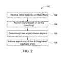
- FIG. 2 is a flow diagram of an example method 100 which may be carried out by system 10.
- Figure 3 illustrates an example set of signals or values derived from signals from sensor 16 (or sensor 16A) utilized in method 100.
- control unit 62 receive signals from sensor 16 based on ventilator airflow/pressure.
- control unit 62 receives signals from pressure sensor 68, the pressure sensor in patient segment 56 on ventilator side 72.
- Line 152 in Figure 3 represents an example series of signals received by control unit 62 from pressure sensor 68 over time. Upward spikes in line 152 indicating increasing pressure on ventilator side 72 of resistive passage 64 as detected by pressure sensor 68. Such upward spikes in line 152 indicate firing or initiation by ventilator 12, wherein ventilator 12 supplies and directs pressurized gas towards the patient 13, increasing the pressure on ventilator side 72.
- control unit 62 also receives signals from sensor 16 (sensor 16A) based on or representing airflow (or patient initiated breathing in some circumstances).
- the lower line 154 represents air flow and air flow direction which correspond to pressure gradient between sensors 66 and 68, wherein the upward direction occurs when the sensed pressure at sensor 68 is greater than the sensed pressure at sensor 66 and wherein a downward direction occurs when the pressure at sensor 68 is less than the sensed pressure at sensor 68.
- the upward spikes of line 154 occur when a patient is initiating a breath such that the pressure at sensor 68 is greater than the sensed pressure at sensor 66.
- the downward spikes of line 154 occur when a patient is exhaling and ventilator 12 is no longer supplying pressurized air such that the sensed pressure at sensor 66 is greater than the sensed pressure at sensor 68.
- control unit 62 utilizes such sets of signals or inputs to determine a phase angle for each breath (inhalation period) based on a relationship between the ventilator firing input and the airflow/breathing input.
- Control unit 62 determines a phase angle based on a relationship between the upward spikes in line 154 (patient initiated breathing) and the upward spikes in line 152 (ventilator firing initiation) to generate a graphical display illustrating a nature of any dis-synchrony between such breathing our airflow and ventilator firing.
- a cycle or Ttot of 2 Pi radians is defined by the time between consecutive ventilator firing peaks in line 152.
- phase angle 2Pi(T2-T1)/Ttot, where time T2 is the time at which ventilator 12 is fired (represented by the upward spike in line 152) and where time T1 is a time at which a patient begins to inhale to initiate the breath (represented by spike in line 154).
- Figures 3 and 4 illustrate two alternative scenarios where the calculated phase angle is positive and is negative.
- Figure 3 illustrates scenario 160 where the patient's initiation of a breath leads the firing of ventilator 12.
- time T1 the time at which the patient initiates a breath
- T2 the time at which the ventilator is fired
- FIG 4 illustrates an alternative scenario 170, wherein the pressurized air being supplied by ventilator 12 is fired at time T2 which precedes the time at which the patient begins breathing as indicated by lower line 154 at time T1.
- time T1 the time at which the patient initiates a breath
- time T2 the time at which the ventilator is fired
- the phase angle is negative. In other implementations, the phase angle may be calculated in other fashions.
- control unit 62 utilizes the calculated phase angle for the breath to graphically or visibly indicate asynchrony or dis-synchrony between gas or airflow and ventilator firing.
- control unit 62 utilizes the calculated phase angle to generate one or more graphics, icons or marks which are displayed on display 60 in which visually indicate such dis-synchrony.
- a caretaker or physician may quickly and easily visibly determine the relationship between the initiation of breathing by a patient and the time at which ventilator 12 is fired to assist such breathing. Based upon a physical determination, the caretaker or physician may then make adjustments to the operation of ventilator 12 through input 58 to enhance the performance of ventilator 12 to address the breathing characteristics of patient 13.
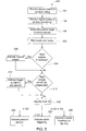
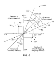
- Figures 5 and 6 illustrate a particular example method 200 and display presentation 300, respectively, for visibly representing the relationship between the initiation of breathing by patient 13 and the time at which ventilator 12 is fired using the aforementioned calculated phase angles.
- steps 102, 104 and 106 correspond to such steps described above with respect to method 100.
- control unit 62 plots consecutive breath pair marks 301.
- a calculated phase angle for a first breath of a consecutive pair of breaths determines the y-axis coordinate or value for the breath pair mark 301A and the calculated phase angle for a second breath of the consecutive pair of breaths determines the x-axis coordinate or value for the breath pair mark 301A.
- a first breath having a positive phase angle and a second breath also having a positive phase angle, forming a first pair of breaths will result in the plotting of a first mark 301 (illustrated with a triangle for ease of discussion) in quadrant 1.
- a third breath having a negative calculated phase angle, forming a second breath pair with the second breath will result in the plotting of a second mark 301 (illustrated with a star) in quadrant 2.
- a fourth breath having a negative calculated phase angle, forming a third breath pair with the third breath will result in the plotting of a third mark (illustrated with a circle) in quadrant 3.
- a fifth breath having a positive calculated phase angle and forming a fourth pair with the fourth breath result in the plotting of a fourth mark (illustrated with a star) in quadrant 4.
- Each breath forms the y-axis coordinate for a first breath pair mark and the x-axis coordinate for a second breath pair mark.
- the plotting of breath pair marks shown in Figure 6 is presented on display 60 by control unit 62.
- breath pair marks plotted in quadrant 1 reflect patient initiated breathing, wherein a patient 13 starts to breathe (starts to inhale) and ventilator 12 responds by firing to supply pressurized air/gas to assist patient 13 with the breath or inhalation.
- the spacing of the breath pair mark from the origin indicates how responsive ventilator 12 is to the patient's initiation of a breath. For example, breath pair marks closer to the origin reflect a more responsive ventilator 12 while breath pair marks farther away from the origin reflect a more insensitive ventilator 12.
- a majority of breath pair marks spaced from the origin by a large distance may indicate the need to adjust and increase a sensitivity of ventilator 12 such that ventilator 12 more quickly responds to the initiation of a breath by patient 13.
- the majority of breath pair mark spaced from the origin by large distance may indicate the need to replace the current ventilator with a more sensitive ventilator or a more sensitive ventilator component for enhanced responsiveness.
- control unit 62 visibly displays or depicts a threshold with respect to the origin beyond which a breath pair mark is deemed to suggest the adjustment of ventilator trigger sensitivity.
- thresholds are depicted by one or more radial trigger sensitivity threshold lines 302, wherein different threshold lines reflect different suggested or recommended degrees of adjustment for trigger sensitivity of ventilator 12.
- trigger sensitivity threshold lines 302 may be omitted, wherein control unit 62 performs an internal comparison with a predefined thresholds and wherein different breath pair marks are illustrated are depicted with different characteristics depending upon their relationship to the predefined thresholds.
- breath pair marks beyond a certain threshold may have one or more of a different color, a different brightness, a different size, a different flashing or flashing frequency, a different shade and the like with respect to other breath pair marks which do not lie beyond the predefined threshold.
- line 302 may be employed with the provision of different characteristics for different breath pair marks based on their relationship to the threshold or relationship to the origin.
- control unit 62 may prompt, through display 60, a caretaker or physician to enter or adjust the value for such trigger sensitivity thresholds through input 58.
- the physician or caretaker may customize such threshold levels, moving such threshold lines 302 towards and away from the origin.
- such threshold indications may be omitted.
- the spacing of a breath pair mark from quadrant bisecting line 306 within quadrant 1 may indicate that a breath initiated by patient 13 was completely missed by ventilator 12.
- patient 13 started to inhale, initiating a breath, but such inhalation was not sensed by ventilator 12 and no assistance (pressurized gas or air) was provided by ventilator 12.
- assistance may be provided by ventilator 12, but wherein such assistance is offered extremely late or early; the firing of ventilator 12 kicking in based upon the predefined lapse of time since the last firing and not in response to the initiation of the breath by patient.
- control unit 62 may further generate control signals causing display 60 to visibly present on the plot of breath pair marks additional missed breath threshold lines 310 which represent thresholds above and below which a breath pair mark (and breath pair) is deemed to indicate a missed breath triggering.
- additional missed breath threshold lines 310 may be omitted, wherein control unit 62 performs an internal comparison with a predefined thresholds and wherein different breath pair marks are illustrated or depicted with different characteristics depending upon their relationship to the predefined thresholds 310.
- breath pair marks outside threshold lines 310 may have one or more of a different color, a different brightness, a different size, a different flashing or flashing frequency, a different shade and the like with respect to other breath pair marks which do not lie beyond the predefined threshold.
- lines 310 may be employed with the provision of different characteristics for different breath pair marks based on their relationship to x and y axes and thresholds 310.
- control unit 62 may prompt, through display 60, a caretaker or physician to enter or adjust the value for such missed breath thresholds through input 58.
- the physician or caretaker may customize such missed breath threshold levels, moving such missed breath threshold lines 310 towards and away from the line 306.
- such missed breath threshold indications may be omitted.
- Breath pair marks plotted in quadrant 3 visibly indicate ventilator initiated breathing, wherein a ventilator 12 fires and supplies pressurized air/gas to patient 13 and wherein patient 13 may be passive.
- Breath pair marks 301 plotted in quadrants 2 and 4 visibly indicate a chaotic triggering or circumstances where the patient 13 is fighting ventilator 12.
- control unit 62 visibly displays all four quadrants for visual inspection. In other implementations, control unit 62 may alternatively display only selected quadrants, such as quadrant 1 representing stable triggering and quadrant 3 indicating a passive patient.
- breath pair marks in different quadrants are illustrated as having different visible characteristics, such as different shapes, in other implementations, breath pair marks may have the same shape or other visible characteristics regardless of which quadrant the breath pair mark 301 lies.
- control unit 62 displays a predefined number of consecutive breath pair marks 301. For example, one implementation, control unit 62 displays 100 breath pair marks 301, removing old breath pair marks 301 on a first in-first out basis. In one implementation, control unit 62 prompts a caretaker or physician for input allowing adjustment of the number of breath pair marks 301 that are concurrently displayed on display 60. In one implementation, control unit 62 further graphically or visibly indicates the aging of breath pair marks 301 corresponding the age of the particular data pointing reflected in the plotting of Figure 6 . Such aging may be graphically depicted with different characteristics depending upon their age are certain age thresholds.
- breath pair marks older than a first aid threshold may have one or more of a different color, a different brightness, a different size, a different flashing or flashing frequency, a different shade and the like with respect to other breath pair marks which do not fall within a certain age range or between certain age thresholds.
- the depiction of breath pair mark aging may be omitted.
- control unit 62 may prompt a caretaker or physician with an option to select the particular visible characteristic differentiation technique used, allowing the physician or caretaker to customize the display for his or her preferences.
- control unit 62 may internally analyze the plotting of breath pair marks and may visibly present textual information based upon the plotted location of the breath pair marks. As a result, the meaning associated with the particular location of the breath pair marks is evident even to those physicians or caretakers unfamiliar with the synchrony display technique shown in Figure 6 .
- controller 62 determines whether a particular breath pair mark 301 lies outside of a missed breath threshold (depicted by line 310 in the display of Figure 6 ).
- control unit 62 generates control signals causing display 60 to specifically indicate the missed breath.
- the specific indication of a missed breath may be made using a graphic or icon known to indicate that a missed breath has occurred or may be achieved with an appropriate textual message, such as "missed breath”.
- control unit 62 determines whether a particular breath pair mark 301 is still outside a trigger sensitivity threshold (depicted by one of lines 302 in the display of Figure 6 ). As indicated by step 212, if control unit 62 determines that the particular breath pair mark 301 is outside a particular sensitively threshold, control unit 62 generates control signals causing display 42 specifically indicate or recommend that the sensitivity of the trigger of ventilator 12 should be adjusted.
- control unit 62 may compare the location of the breath pair mark 301 to several different threshold levels and generate a different adjustment recommendation depending upon which of the pressure levels is exceeded by the location of the breath pair mark 301 (or the values associated with the breath pair mark 301).
- control unit 62 further identifies the particular quadrant in which a particular breath mark 301 is located using the plot location or the corresponding values of the particular breath mark. As indicated in step 222, if control unit 62 determines that a particular breath mark is in quadrant 1, control unit 62 generates control signals causing display 60 to specifically indicate that ventilator triggering a stable for that breath mark. Such an indication may be made using a graphic or icon known to the physician or caretaker to indicate stable triggering or may be achieved with appropriate textual message such as "stable triggering".
- control unit 62 determines that a particular breath mark is in quadrant 3
- control unit 62 generates control signals causing display 60 to specifically indicate a passive patient.
- Such an indication may be made using a graphic or icon known to the physician or caretaker to indicate a passive patient or may be achieved with appropriate textual message such as "passive patient".
- control unit 62 determines that a particular breath mark is in quadrant 4
- control unit 62 generates control signals causing display 60 to specifically indicate a chaotic breathing or patient fighting.
- Such an indication may be made using a graphic or icon known to the physician or caretaker to indicate a chaotic breathing or patient fighting or may be achieved with appropriate textual message such as "chaotic breathing" or "fighting patient".
- such messages as discussed with respect to step 222, 224 226 may be streamed on display 60. In other implementations, such messages may be displayed in other fashions.
- control unit 62 may output any of the messages identified with regard to steps 222, 224 226 only at predefined time periods or intervals and may select which of the messages is indicated based upon a statistical analysis of the number of breath pair marks falling within each of the quadrants. For example, control unit 62 may be programmed or configured to only output such a message every 30 seconds, wherein the time interval may be selectively adjustable by caretaker or physician through input 38. Control unit 62 may be programmed or configured to only indicate stable triggering (per step 222) when a predefined percentage or number of breath pair marks falls within the first quadrant.
- control unit 62 may be programmed or configured to only indicate a passive patient (per step 224) or to indicate chaotic breathing or fighting up and per step 226) when a predefined percentage or number of breath marks falls within the third quadrant or within the second or fourth quadrant, respectively.
- the predefined threshold for the number or percentage of breath marks falling within a particular quadrant or quadrants at which such messages are displayed may be selectively adjusted by caretaker or physician through input 58.
- the severity of a passive patient may justify use of a lower threshold number or percentage of breath marks to trigger the display of the passive patient message or warning.
- the messages possibly provided through steps 204-226 occur concurrently with the presentation of display 300 in Figure 6 .
- such messages may be presented on display 60, wherein display 300 is not presented.
- the physician or caretaker may selectively choose, through input 58, whether one or both of the messages of steps 204-226 or the plotting of breath pair marks 301 per step 202 as exemplified in display 300 are presented.
- control unit 62 may alternatively or additionally provide a graphical display based upon a phase angle relationship between the cessation of ventilator assistance and airflow corresponding to exhalation by the patient.
- the phase angle for a particular breath exhalation would be calculated wherein a cycle or Ttot' of 2 Pi radians is defined by the time between consecutive ventilator drops or sensations in line 152 (shown in Figure 3 ).
- the cycle may be derived from other values.
- the cycle used for the calculation of an exhalation phase angle may alternatively comprise Ttot.
- other values may be used for the cycle for calculating a breath phase angle.
- phase angle (exhalation) 2Pi(T2'-T1')/Ttot', where time T2' is the time at which ventilator 12 is cessated or stopped (represented by the steep downward trend in line 152 of Figure 3 ) and where time T1' is a time at which a patient begins to exhale following a breath (represented by the negative or downward spike in line 154 of Figure 3 ).
- time T2' is the time at which ventilator 12 is cessated or stopped (represented by the steep downward trend in line 152 of Figure 3 )
- time T1' is a time at which a patient begins to exhale following a breath (represented by the negative or downward spike in line 154 of Figure 3 ).
- the exhalation phase angles for two consecutive exhalation pairs would be used to define y and x coordinates for an exhalation pair mark.
- control unit 62 plots consecutive exhalation pair marks.
- a calculated phase angle for a first exhalation of a consecutive pair of exhalations determines the y-axis coordinate or value for the exhalation pair mark and the calculated phase angle for a second exhalation of the consecutive pair of exhalations determines the x-axis coordinate or value for the exhalation pair mark.
- a first exhalation having a positive phase angle and a second exhalation also having a positive phase angle, forming a first pair of exhalations will result in the plotting of a first mark in quadrant 1.
- a third exhalation having a negative calculated phase angle, forming a second exhalation pair with the second exhalation will result in the plotting of a second mark in quadrant 2.
- a fourth exhalation having a negative calculated phase angle, forming a third exhalation pair with the third exhalation, will result in the plotting of a third exhalation mark in quadrant 3.
- a fifth exhalation having a positive calculated phase angle and forming a fourth pair with the fourth exhalation result in the plotting of a fourth mark in quadrant 4.
- Each exhalation forms the y-axis coordinate for a first exhalation pair mark and the x-axis coordinate for a second exhalation pair mark.
- the plotting of exhalation pair marks (similar to as shown in Figure 6 ) is presented on display 60 by control unit 62.
Landscapes
- Health & Medical Sciences (AREA)
- Emergency Medicine (AREA)
- Pulmonology (AREA)
- Engineering & Computer Science (AREA)
- Anesthesiology (AREA)
- Biomedical Technology (AREA)
- Heart & Thoracic Surgery (AREA)
- Hematology (AREA)
- Life Sciences & Earth Sciences (AREA)
- Animal Behavior & Ethology (AREA)
- General Health & Medical Sciences (AREA)
- Public Health (AREA)
- Veterinary Medicine (AREA)
- Measurement Of The Respiration, Hearing Ability, Form, And Blood Characteristics Of Living Organisms (AREA)
Abstract
Description
- Ventilators are machines used to assist or replace spontaneous breathing of a patient. In some circumstances, a ventilator may also be used to supply anesthetic agents to the patient undergoing certain medical procedures. With existing ventilators, monitoring patient breathing and ventilator performance may be difficult. A caretaker may not easily determine whether a patient is struggling to breathe, whether a patient is fighting the assistance of the ventilator or whether the ventilator is optimally operating to assist the patient with his or her breathing.
- According to an aspect of the invention there is provided an apparatus comprising: a display; and a processing unit to receive a first input based on airflow in a ventilator for a breath and a second input based upon ventilator firing for the breath, wherein the processing unit is configured to determine a phase angle based on a relationship between the first input and the second input and to provide an indication on the display of a nature of dis-synchrony of airflow and ventilator firing based on the phase angle.
-
-
Figure 1 is a schematic illustration of an example mechanical ventilation system. -
Figure 1A is a fragmentary schematic illustration of an example sensor of the system ofFigure 1 . -
Figure 2 is a flow diagram of an example method that may be carried out by the system ofFigure 1 . -
Figure 3 is a diagram illustrating signals and values derived from signals from a first example ventilator synchrony scenario and used by the system ofFigure 1 in carrying out the method ofFigure 2 . -
Figure 4 is a diagram illustrating signals and values derived from signals from a second example ventilator synchrony scenario and used by the system ofFigure 1 in carrying out the method ofFigure 2 . -
Figure 5 is a flow diagram of another example method that may carried out by the system ofFigure 1 . -
Figure 6 is a diagram of an example display that may be presented by the system ofFigure 1 . -
Figure 1 schematically illustrates an example of amechanical ventilation system 10.Ventilation system 10 provides a pneumatic circuit that carries breathing gas to and exhaled air from apatient 13 to assistpatient 13 in breathing. As will be described hereafter,ventilation system 10 provides a graphic that allows a caretaker to more quickly and easily monitor patient breathing and ventilator performance.Ventilation system 10 enables a caretaker to more easily determine whether a patient is struggling to breathe, whether a patient is fighting the assistance of the ventilator or whether the ventilators optimally operating to assist the patient with his or her breathing.Ventilation system 10 comprisesventilator 12,breathing circuit 14,sensor 16 and display andcontrol unit 18. -
Ventilator 12 supplies gas, such as air or air including anesthetics, drugs or the like, topatient 13 throughbreathing circuit 14 and receives exhaled air throughbreathing circuit 14. In the example illustrated,ventilator 12 receives air fromair source 20 throughconduit 22 and receives oxygen (O2) from an oxygen source 24 (such as a container of compressed oxygen) throughconduit 26.Ventilator 12 comprisesvalves sensors valve 38 andsensor 40 and controller orprocessing unit 42.Valves conduit 44 to breathingcircuit 14.Sensors unit 38. -
Valve 38 comprises a valve mechanism connected tobreathing circuit 14 byconduit 46 so as to control the flow of exhaled air received frombreathing circuit 14 to thedischarge conduit 48.Sensor 40 comprises a device to sense the flow of exhaled air todischarge port 48. Such sensed values for the exhaled air are further transmitted to controller orprocessing unit 38. -
Processing unit 42 generates control signals controlling the operation ofvalves processing unit 42 may be included as part of one or more processing units associated withdisplay control unit 18. -
Breathing circuit 14 delivers breathing gas (air, oxygen and possibly other additives such as anesthetics, medicines and the like) fromventilator 12 topatient 13 while also directing exhaled air frompatient 13 tosystem 10 andventilator 12.Breathing circuit 14 comprises inspiratory section orsegment 50,expiration segment 52,Y connector 54 andpatient segment 56.Inspiratory segment 50 extends from and is pneumatically connected toconduit 44 at one end andY connector 54 at the other end.Segment 50 delivers gases fromconduit 44 topatient segment 56 during forced, assisted or voluntary inhalation bypatient 13.Exhalation segment 52 delivers exhaled gases are exhaled air frompatient segment 56 to conduit 46.Y connector 54 connects each ofsegments patient segment 56.Patient segment 56 extends fromY connector 54 topatient 13.Patient segment 56 may include devices for pneumatically connecting withpatient 13 such as through the nose, mouth or trachea ofpatient 13. - During inspiration (inhalation), breathing air is delivered through
patient segment 56 and into the lungs ofpatient 13. During expiration or exhalation, expired or exhaled breathing air exits the lungs thepatient 13 and is received intopatient segment 56. The expired breathing air is communicated or transmitted throughpatient segment 56, throughY connector 54 and intoexpiration segment 52. Although not illustrated, in other implementations,ventilation system 10 may comprise additional devices or systems. For example, in one implementation,system 10 may additionally include a nebulizer positioned betweenventilator 12 andinspiratory section 50 to introduce a medical drug or anesthetic agent to breathing air for the patient. In yet other implementations,breathing circuit 14 may comprise a component such as a humidifier to humidify the breathing air, a heater to heat the breathing air or a water/vapor trap to remove excess moisture from a particular segment or section ofventilation system 10. - In some implementations,
ventilator 12 may additionally include a carbon dioxide scavenger which removes carbon dioxide from exhaled air and returns or recycles the air by conducting such recycled air to conduit 22. In one implementation,ventilator 12 utilizes a bellows to pressurize air being supplied to conduit 50. For example, in one implementation,ventilator 12 selectively supplies and withdraws pressurized air to and from an exterior of a bellows assembly. During inhalation,ventilator 12 supplies gas or air to the exterior of the bellows, collapsing the bellows to force gas within bellows to through the carbon dioxide scavenger and to thebreathing circuit 14 and the patient's lungs. During exhalation, expelled gas from the patient's lungs passes throughvalve 38 to fill the bellows. In other implementations, the noted carbon dioxide scavenger as well as the bellows may be omitted. -
Sensor 16 comprise a device configured to sense or detect pressure and/or flow of air (with or without additives) corresponding to forced, voluntary or assisted inhalation and exhalation bypatient 13. In the example illustrated,sensor 16 is located withinpatient segment 56. In other implementations,sensor 16 may be provided at other locations. For example, in other implementations,sensor 16 may be provided as part of a mouthpiece through whichpatient 13 inhales and exhales. -
Figure 1A illustratessensor 16A, one example ofsensor 16. As shown byFigure 1A ,sensor 16A comprises a pneumotachometer which senses pressures on opposite sides of a flow resister and utilizes a pressure gradient to determine flow and direction. In the example illustrated,sensor 16A includes aflow resister passage 64 and pressure transducers orsensors passage 64 comprise a constriction through which gas or air flows, causing pressure buildups on either side ofpassage 64 depending upon the direction of airflow.Flow resister passage 64 dividespatient segment portion 56 into apatient side 70 and aventilator side 72 ofresistive flow passage 64.Pressure sensor 66 senses a patient side pressure whilepressure sensor 68 senses a ventilator side pressure. Such pressure signals are transmitted or communicated to display andcontrol unit 18. - Display and
control unit 18 receives signals fromsensor 16 and provides a visible graphical indication of a nature of dis-synchrony of patient generated airflow and ventilator operation. Display andcontrol unit 18 utilizes such signals to determine a phase angle based relationship between an input based on airflow for a breath and input based upon ventilator firing for the breath. For purposes of this disclosure, the phrase "based on airflow for a breath" or "based on airflow in a ventilator for a breath" shall mean a signal or input that has a relationship to airflow for a breath or breathing. Such a signal or input may comprise signals pertaining to a sensed pressure or sensed pressure differentials in a passage. For example, a patient's breathing will create airflow in a passage, wherein such airflow will create pressure differentials across a pneumotachometer and wherein signals from the pneumotachometer are signals based upon such airflow. For purposes of this disclosure, the phrase "based upon ventilator firing for the breath" shall mean an input or signal that has a relationship to the firing of the ventilator for a breath. Such an input or signal may comprise sensed pressure or sensed pressure differentials in a passage which may occur as a result of the firing of a ventilator. The phase angle based relationship is used to generate the graphical indication of dis-synchrony. The graphical or visually discernible indication of dis-synchrony allows a physician or caretaker to quickly and easily determine, at a glance, the relationship between the patient's breathing in the operation of the ventilator. -
Display control unit 18 comprisesinputs 58,display 60 andcontrol unit 62.Inputs 58 comprise one or more devices by which a physician or caretaker may enter or input commands, instructions or selections formechanical ventilation system 10. In one implementation,input 58 comprise a series or arrangement of knobs, buttons, dials, toggle switches, rocker switches and the like. In one implementation,input 58 may alternatively or additionally include a keyboard, a touchpad, a microphone associated with speech recognition software, a stylus, and a touch screen. In one implementation, the touch screen may be incorporated as part ofdisplay 60. -
Display 60 comprises a monitor, screen or panel by which graphics and text may be visibly displayed for viewing by a physician or caretaker. In one implementation,display 60 may comprise an light emitting diode screen. In other implementations,display 60 may utilize other display technologies. In the example illustrated,inputs 58 anddisplay 60 are illustrated as being integral are as part ofsystem 10. In other implementations,inputs 58 anddisplay 60 may be provided part of a separate electronic device, such as a separate portable electronic device, wherein signals from the separate electronic device are transmitted to and received bycontrol unit 62 ofsystem 10. For example,display 60 andinputs 58 may alternatively incorporate as a portable electronic device such as a personal data assistant, flash player, tablet computer, laptop computer in the like.Control unit 62 comprises one or more processing units configured to receive signals from processingunit 42 for analysis and the presentation of information ondisplay 60, to generate control signals which are transmitted tocontroller 42 based upon inputs or selections received throughinput 58, and to receive signals fromsensor 16 to generate control signals for directingdisplay 60 to present a visible graphical indication of a nature of dis-synchrony of patient generated airflow and ventilator operation.Control unit 62 follows directions or instructions, such as software or code, contained in one or more non-transient computer-readable mediums or persistent storage devices. In some implementations,control unit 62 may be located remote fromventilator 12, wherein such control signals and analysis are performed remotely fromventilator 12, such as through cloud computing. -
Figure 2 is a flow diagram of anexample method 100 which may be carried out bysystem 10.Figure 3 illustrates an example set of signals or values derived from signals from sensor 16 (orsensor 16A) utilized inmethod 100. As indicated bystep 102,control unit 62 receive signals fromsensor 16 based on ventilator airflow/pressure. In one example wheresensor 16A is employed,control unit 62 receives signals frompressure sensor 68, the pressure sensor inpatient segment 56 onventilator side 72.Line 152 inFigure 3 represents an example series of signals received bycontrol unit 62 frompressure sensor 68 over time. Upward spikes inline 152 indicating increasing pressure onventilator side 72 ofresistive passage 64 as detected bypressure sensor 68. Such upward spikes inline 152 indicate firing or initiation byventilator 12, whereinventilator 12 supplies and directs pressurized gas towards thepatient 13, increasing the pressure onventilator side 72. - As indicated by
step 104,control unit 62 also receives signals from sensor 16 (sensor 16A) based on or representing airflow (or patient initiated breathing in some circumstances). As shown byFigure 3 , thelower line 154 represents air flow and air flow direction which correspond to pressure gradient betweensensors sensor 68 is greater than the sensed pressure atsensor 66 and wherein a downward direction occurs when the pressure atsensor 68 is less than the sensed pressure atsensor 68. In other words, the upward spikes ofline 154 occur when a patient is initiating a breath such that the pressure atsensor 68 is greater than the sensed pressure atsensor 66. The downward spikes ofline 154 occur when a patient is exhaling andventilator 12 is no longer supplying pressurized air such that the sensed pressure atsensor 66 is greater than the sensed pressure atsensor 68. - As indicated by
step 106 inFigure 2 ,control unit 62 utilizes such sets of signals or inputs to determine a phase angle for each breath (inhalation period) based on a relationship between the ventilator firing input and the airflow/breathing input.Control unit 62 determines a phase angle based on a relationship between the upward spikes in line 154 (patient initiated breathing) and the upward spikes in line 152 (ventilator firing initiation) to generate a graphical display illustrating a nature of any dis-synchrony between such breathing our airflow and ventilator firing. In particular, a cycle or Ttot of 2 Pi radians is defined by the time between consecutive ventilator firing peaks inline 152. The phase angle for an individual breath is determined according to the equation: phase angle = 2Pi(T2-T1)/Ttot, where time T2 is the time at whichventilator 12 is fired (represented by the upward spike in line 152) and where time T1 is a time at which a patient begins to inhale to initiate the breath (represented by spike in line 154). -
Figures 3 and 4 illustrate two alternative scenarios where the calculated phase angle is positive and is negative.Figure 3 illustratesscenario 160 where the patient's initiation of a breath leads the firing ofventilator 12. As shown byFigure 3 , the time at which the patient initiates a breath (time T1) perceive the time at which the ventilator is fired (T2). As a result, the phase angle is positive. -
Figure 4 illustrates analternative scenario 170, wherein the pressurized air being supplied byventilator 12 is fired at time T2 which precedes the time at which the patient begins breathing as indicated bylower line 154 at time T1. As shown byFigure 4 , the time at which the patient initiates a breath (time T1) succeeds or follows the time at which the ventilator is fired (time T2). As a result, the phase angle is negative. In other implementations, the phase angle may be calculated in other fashions. - As indicated by
step 108 inFigure 2 , upon calculating the phase angle,control unit 62 utilizes the calculated phase angle for the breath to graphically or visibly indicate asynchrony or dis-synchrony between gas or airflow and ventilator firing. In particular,control unit 62 utilizes the calculated phase angle to generate one or more graphics, icons or marks which are displayed ondisplay 60 in which visually indicate such dis-synchrony. As a result, a caretaker or physician may quickly and easily visibly determine the relationship between the initiation of breathing by a patient and the time at whichventilator 12 is fired to assist such breathing. Based upon a physical determination, the caretaker or physician may then make adjustments to the operation ofventilator 12 throughinput 58 to enhance the performance ofventilator 12 to address the breathing characteristics ofpatient 13. -
Figures 5 and6 illustrate aparticular example method 200 anddisplay presentation 300, respectively, for visibly representing the relationship between the initiation of breathing bypatient 13 and the time at whichventilator 12 is fired using the aforementioned calculated phase angles. As shown byFigure 5 ,steps method 100. As indicated bystep 202,control unit 62 plots consecutive breath pair marks 301. As shown byFigure 6 , a calculated phase angle for a first breath of a consecutive pair of breaths determines the y-axis coordinate or value for thebreath pair mark 301A and the calculated phase angle for a second breath of the consecutive pair of breaths determines the x-axis coordinate or value for thebreath pair mark 301A. As shown byFigure 6 , a first breath having a positive phase angle and a second breath also having a positive phase angle, forming a first pair of breaths, will result in the plotting of a first mark 301 (illustrated with a triangle for ease of discussion) inquadrant 1. A third breath having a negative calculated phase angle, forming a second breath pair with the second breath, will result in the plotting of a second mark 301 (illustrated with a star) inquadrant 2. A fourth breath having a negative calculated phase angle, forming a third breath pair with the third breath, will result in the plotting of a third mark (illustrated with a circle) inquadrant 3. A fifth breath having a positive calculated phase angle and forming a fourth pair with the fourth breath result in the plotting of a fourth mark (illustrated with a star) in quadrant 4. Each breath forms the y-axis coordinate for a first breath pair mark and the x-axis coordinate for a second breath pair mark. - In one implementation, the plotting of breath pair marks shown in
Figure 6 is presented ondisplay 60 bycontrol unit 62. Visual inspection of the quadrant in which a particular breath pair mark lies as well as its relationship to the origin (x=0, y=0) provides the caretaker or physician with immediate information as to the synchrony or dis-synchrony between patient breathing and ventilator firing. For example, breath pair marks plotted inquadrant 1 reflect patient initiated breathing, wherein a patient 13 starts to breathe (starts to inhale) andventilator 12 responds by firing to supply pressurized air/gas to assistpatient 13 with the breath or inhalation. - The spacing of the breath pair mark from the origin indicates how
responsive ventilator 12 is to the patient's initiation of a breath. For example, breath pair marks closer to the origin reflect a moreresponsive ventilator 12 while breath pair marks farther away from the origin reflect a moreinsensitive ventilator 12. A majority of breath pair marks spaced from the origin by a large distance may indicate the need to adjust and increase a sensitivity ofventilator 12 such thatventilator 12 more quickly responds to the initiation of a breath bypatient 13. In some circumstances, the majority of breath pair mark spaced from the origin by large distance may indicate the need to replace the current ventilator with a more sensitive ventilator or a more sensitive ventilator component for enhanced responsiveness. - In the example illustrated,
control unit 62 visibly displays or depicts a threshold with respect to the origin beyond which a breath pair mark is deemed to suggest the adjustment of ventilator trigger sensitivity. In the example illustrated, such thresholds are depicted by one or more radial triggersensitivity threshold lines 302, wherein different threshold lines reflect different suggested or recommended degrees of adjustment for trigger sensitivity ofventilator 12. In other implementations, such triggersensitivity threshold lines 302 may be omitted, whereincontrol unit 62 performs an internal comparison with a predefined thresholds and wherein different breath pair marks are illustrated are depicted with different characteristics depending upon their relationship to the predefined thresholds. For example, breath pair marks beyond a certain threshold may have one or more of a different color, a different brightness, a different size, a different flashing or flashing frequency, a different shade and the like with respect to other breath pair marks which do not lie beyond the predefined threshold. In some implementations,line 302 may be employed with the provision of different characteristics for different breath pair marks based on their relationship to the threshold or relationship to the origin. - In one implementation,
control unit 62 may prompt, throughdisplay 60, a caretaker or physician to enter or adjust the value for such trigger sensitivity thresholds throughinput 58. As a result, the physician or caretaker may customize such threshold levels, movingsuch threshold lines 302 towards and away from the origin. In yet other implementations, such threshold indications may be omitted. - The spacing of a breath pair mark from
quadrant bisecting line 306 withinquadrant 1 may indicate that a breath initiated bypatient 13 was completely missed byventilator 12. In other words, patient 13 started to inhale, initiating a breath, but such inhalation was not sensed byventilator 12 and no assistance (pressurized gas or air) was provided byventilator 12. In some instances, assistance may be provided byventilator 12, but wherein such assistance is offered extremely late or early; the firing ofventilator 12 kicking in based upon the predefined lapse of time since the last firing and not in response to the initiation of the breath by patient. - In one implementation,
control unit 62 may further generate controlsignals causing display 60 to visibly present on the plot of breath pair marks additional missedbreath threshold lines 310 which represent thresholds above and below which a breath pair mark (and breath pair) is deemed to indicate a missed breath triggering. In other implementations, such missedbreath threshold lines 310 may be omitted, whereincontrol unit 62 performs an internal comparison with a predefined thresholds and wherein different breath pair marks are illustrated or depicted with different characteristics depending upon their relationship to thepredefined thresholds 310. For example, breath pair marks outsidethreshold lines 310 may have one or more of a different color, a different brightness, a different size, a different flashing or flashing frequency, a different shade and the like with respect to other breath pair marks which do not lie beyond the predefined threshold. In some implementations,lines 310 may be employed with the provision of different characteristics for different breath pair marks based on their relationship to x and y axes andthresholds 310. - In one implementation,
control unit 62 may prompt, throughdisplay 60, a caretaker or physician to enter or adjust the value for such missed breath thresholds throughinput 58. As a result, the physician or caretaker may customize such missed breath threshold levels, moving such missedbreath threshold lines 310 towards and away from theline 306. In yet other implementations, such missed breath threshold indications may be omitted. - Breath pair marks plotted in
quadrant 3 visibly indicate ventilator initiated breathing, wherein aventilator 12 fires and supplies pressurized air/gas topatient 13 and whereinpatient 13 may be passive. Breath pair marks 301 plotted inquadrants 2 and 4 visibly indicate a chaotic triggering or circumstances where thepatient 13 is fightingventilator 12. In the example illustrated,control unit 62 visibly displays all four quadrants for visual inspection. In other implementations,control unit 62 may alternatively display only selected quadrants, such asquadrant 1 representing stable triggering andquadrant 3 indicating a passive patient. Although breath pair marks in different quadrants are illustrated as having different visible characteristics, such as different shapes, in other implementations, breath pair marks may have the same shape or other visible characteristics regardless of which quadrant thebreath pair mark 301 lies. - In one implementation,
control unit 62 displays a predefined number of consecutive breath pair marks 301. For example, one implementation,control unit 62displays 100 breath pair marks 301, removing old breath pair marks 301 on a first in-first out basis. In one implementation,control unit 62 prompts a caretaker or physician for input allowing adjustment of the number of breath pair marks 301 that are concurrently displayed ondisplay 60. In one implementation,control unit 62 further graphically or visibly indicates the aging of breath pair marks 301 corresponding the age of the particular data pointing reflected in the plotting ofFigure 6 . Such aging may be graphically depicted with different characteristics depending upon their age are certain age thresholds. For example, breath pair marks older than a first aid threshold may have one or more of a different color, a different brightness, a different size, a different flashing or flashing frequency, a different shade and the like with respect to other breath pair marks which do not fall within a certain age range or between certain age thresholds. In yet other implementations, the depiction of breath pair mark aging may be omitted. In each of the implementations wheremarks 301 are provided with different visible characteristics to indicate relationships with respect to sensitivity, missed breath or age thresholds,control unit 62 may prompt a caretaker or physician with an option to select the particular visible characteristic differentiation technique used, allowing the physician or caretaker to customize the display for his or her preferences. - As indicated by the remainder of
method 200 andFigure 5 ,control unit 62 may internally analyze the plotting of breath pair marks and may visibly present textual information based upon the plotted location of the breath pair marks. As a result, the meaning associated with the particular location of the breath pair marks is evident even to those physicians or caretakers unfamiliar with the synchrony display technique shown inFigure 6 . As indicated bystep 204,controller 62 determines whether a particularbreath pair mark 301 lies outside of a missed breath threshold (depicted byline 310 in the display ofFigure 6 ). As indicated bystep 206, ifcontroller 62 determines that a particular breath pair mark lies outside the missed breath threshold,control unit 62 generates controlsignals causing display 60 to specifically indicate the missed breath. The specific indication of a missed breath may be made using a graphic or icon known to indicate that a missed breath has occurred or may be achieved with an appropriate textual message, such as "missed breath". - As indicated by
step 210, ifcontrol unit 62 determines that a particularbreath pair mark 301 is within the missed breath thresholds,control unit 62 determines whether a particularbreath pair mark 301 is still outside a trigger sensitivity threshold (depicted by one oflines 302 in the display ofFigure 6 ). As indicated bystep 212, ifcontrol unit 62 determines that the particularbreath pair mark 301 is outside a particular sensitively threshold,control unit 62 generates controlsignals causing display 42 specifically indicate or recommend that the sensitivity of the trigger ofventilator 12 should be adjusted. The specific indication of the need for an adjustment to ventilator trigger sensitivity may be made using a graphic or icon known to indicate an adjustment to trigger sensitivity should be made or may be achieved with appropriate textual message such as "adjustment of trigger recommended". In some implementations, the specific indication may further or additionally indicate the direction and/or the extent of adjustment that is recommended. For example,control unit 62 may compare the location of thebreath pair mark 301 to several different threshold levels and generate a different adjustment recommendation depending upon which of the pressure levels is exceeded by the location of the breath pair mark 301 (or the values associated with the breath pair mark 301). - As indicated by
step 220,control unit 62 further identifies the particular quadrant in which aparticular breath mark 301 is located using the plot location or the corresponding values of the particular breath mark. As indicated instep 222, ifcontrol unit 62 determines that a particular breath mark is inquadrant 1,control unit 62 generates controlsignals causing display 60 to specifically indicate that ventilator triggering a stable for that breath mark. Such an indication may be made using a graphic or icon known to the physician or caretaker to indicate stable triggering or may be achieved with appropriate textual message such as "stable triggering". - As indicated by
step 224, ifcontrol unit 62 determines that a particular breath mark is inquadrant 3,control unit 62 generates controlsignals causing display 60 to specifically indicate a passive patient. Such an indication may be made using a graphic or icon known to the physician or caretaker to indicate a passive patient or may be achieved with appropriate textual message such as "passive patient". - As indicated by
step 226, ifcontrol unit 62 determines that a particular breath mark is in quadrant 4,control unit 62 generates controlsignals causing display 60 to specifically indicate a chaotic breathing or patient fighting. Such an indication may be made using a graphic or icon known to the physician or caretaker to indicate a chaotic breathing or patient fighting or may be achieved with appropriate textual message such as "chaotic breathing" or "fighting patient". In one implementation, such messages as discussed with respect to step 222, 224 226 may be streamed ondisplay 60. In other implementations, such messages may be displayed in other fashions. - In some implementations,
control unit 62 may output any of the messages identified with regard tosteps control unit 62 may be programmed or configured to only output such a message every 30 seconds, wherein the time interval may be selectively adjustable by caretaker or physician throughinput 38.Control unit 62 may be programmed or configured to only indicate stable triggering (per step 222) when a predefined percentage or number of breath pair marks falls within the first quadrant. Likewise,control unit 62 may be programmed or configured to only indicate a passive patient (per step 224) or to indicate chaotic breathing or fighting up and per step 226) when a predefined percentage or number of breath marks falls within the third quadrant or within the second or fourth quadrant, respectively. The predefined threshold for the number or percentage of breath marks falling within a particular quadrant or quadrants at which such messages are displayed may be selectively adjusted by caretaker or physician throughinput 58. In certain circumstances, the severity of a passive patient may justify use of a lower threshold number or percentage of breath marks to trigger the display of the passive patient message or warning. In the example illustrated, the messages possibly provided through steps 204-226 occur concurrently with the presentation ofdisplay 300 inFigure 6 . In other implementations, such messages may be presented ondisplay 60, whereindisplay 300 is not presented. In some implementations, the physician or caretaker may selectively choose, throughinput 58, whether one or both of the messages of steps 204-226 or the plotting of breath pair marks 301 perstep 202 as exemplified indisplay 300 are presented. - In the example illustrated, the dis-synchrony between ventilator firing and initiation of a breath by a patient is graphically displayed or messages or warnings are presented based upon such dis-synchrony. In other implementations, other relationships between ventilator operation in patient breathing may be visually depicted in a similar manner. For example, instead of providing a graphical display based upon a phase angle relationship between the firing of a ventilator and airflow into the patient (the initiation of breath by patient in some circumstances),
control unit 62 may alternatively or additionally provide a graphical display based upon a phase angle relationship between the cessation of ventilator assistance and airflow corresponding to exhalation by the patient. In such an alternative implementation, the phase angle for a particular breath exhalation would be calculated wherein a cycle or Ttot' of 2 Pi radians is defined by the time between consecutive ventilator drops or sensations in line 152 (shown inFigure 3 ). In other implementations, the cycle may be derived from other values. For example, the cycle used for the calculation of an exhalation phase angle may alternatively comprise Ttot. In other implementations, other values may be used for the cycle for calculating a breath phase angle. The phase angle for an individual exhalation is determined according to the equation: phase angle (exhalation) = 2Pi(T2'-T1')/Ttot', where time T2' is the time at whichventilator 12 is cessated or stopped (represented by the steep downward trend inline 152 ofFigure 3 ) and where time T1' is a time at which a patient begins to exhale following a breath (represented by the negative or downward spike inline 154 ofFigure 3 ). As withdisplay 300 andFigure 6 , the exhalation phase angles for two consecutive exhalation pairs (exhalations following two breaths) would be used to define y and x coordinates for an exhalation pair mark. - In such an alternative implementation,
control unit 62 plots consecutive exhalation pair marks. A calculated phase angle for a first exhalation of a consecutive pair of exhalations determines the y-axis coordinate or value for the exhalation pair mark and the calculated phase angle for a second exhalation of the consecutive pair of exhalations determines the x-axis coordinate or value for the exhalation pair mark. A first exhalation having a positive phase angle and a second exhalation also having a positive phase angle, forming a first pair of exhalations, will result in the plotting of a first mark inquadrant 1. A third exhalation having a negative calculated phase angle, forming a second exhalation pair with the second exhalation, will result in the plotting of a second mark inquadrant 2. A fourth exhalation having a negative calculated phase angle, forming a third exhalation pair with the third exhalation, will result in the plotting of a third exhalation mark inquadrant 3. A fifth exhalation having a positive calculated phase angle and forming a fourth pair with the fourth exhalation result in the plotting of a fourth mark in quadrant 4. Each exhalation forms the y-axis coordinate for a first exhalation pair mark and the x-axis coordinate for a second exhalation pair mark. - In one implementation, the plotting of exhalation pair marks (similar to as shown in
Figure 6 ) is presented ondisplay 60 bycontrol unit 62. Visual inspection of the quadrant in which a particular exhalation pair mark lies as well as its relationship to the origin (x=0, y=0) provides the caretaker or physician with immediate information as to the synchrony or dis-synchrony between patient exhalation and ventilator pauses. - Although the present disclosure has been described with reference to example embodiments, workers skilled in the art will recognize that changes may be made in form and detail without departing from the spirit and scope of the claimed subject matter. For example, although different example embodiments may have been described as including one or more features providing one or more benefits, it is contemplated that the described features may be interchanged with one another or alternatively be combined with one another in the described example embodiments or in other alternative embodiments. Because the technology of the present disclosure is relatively complex, not all changes in the technology are foreseeable. The present disclosure described with reference to the example embodiments and set forth in the following claims is manifestly intended to be as broad as possible. For example, unless specifically otherwise noted, the claims reciting a single particular element also encompass a plurality of such particular elements.
- Various aspects and embodiments of the present invention are defined by the following numbered clauses:
- 1. An apparatus comprising:
- a display; and
- a processing unit to receive a first input based on airflow in a ventilator for a breath and a second input based upon ventilator firing for the breath, wherein the processing unit is configured to determine a phase angle based on a relationship between the first input and the second input and to provide an indication on the display of a nature of dis-synchrony of airflow and ventilator firing based on the phase angle.
- 2. The apparatus of
clause 1, wherein the indication comprises a visual depiction of a phase angle relationship between successive breaths. - 3. The apparatus of
clause 1 orclause 2, wherein the visual depiction comprises a graphical plotting of the phase angle relationship of successive breath pairs with respect to x and y axes intersecting one another at an origin, the graphical plotting comprises a plurality of breath pair markings, each marking having an x-coordinate value based upon the phase angle of one of the successive breaths and a y-coordinate value based upon the phase angle of the other of the successive breaths. - 4. The apparatus of any preceding clause, wherein the processing unit is further configured to visually depict thresholds above and below which a breath pair is deemed to indicate a missed breath triggering.
- 5. The apparatus of any preceding clause, further comprising an input to the processing unit, wherein the thresholds are adjustable in response to selections provided to the input.
- 6. The apparatus of any preceding clause, wherein the processing unit is further configured to provide a visual indication of an age of each breath pair mark.
- 7. The apparatus of any preceding clause, wherein the processing unit is further configured to visually depict a threshold with respect to the origin beyond which a breath pair mark is deemed to suggest the adjustment of ventilator trigger sensitivity.
- 8. The apparatus of any preceding clause, wherein the processing unit is configured to indicate a chaotic breathing characteristic or a patient fighting the ventilator characteristic in response to a phase angle relationship between successive breaths falling into either a second quadrant or a fourth quadrant.
- 9. The apparatus of any preceding clause, wherein the processing unit is configured to indicate a passive patient characteristic in response to a phase angle relationship of successive breaths falling in a third quadrant.
- 10. The apparatus of any preceding clause, wherein the processing unit is configured to provide a suggestion for trigger sensitivity adjustment in response to a phase angle relationship of successive breaths lying beyond a predetermined distance from an origin.
- 11. A method comprising:
- for each of a plurality of breaths, determining a phase angle between a first signal based on ventilator airflow for a breath and a second signal based upon ventilator firing for the breath; and
- providing an indication of a nature of dis-synchrony of airflow and ventilator firing based on the phase angle.
- 12. The method of any preceding clause, wherein the indication comprise a visual depiction of a phase angle relationship between successive breaths.
- 13. The method of any preceding clause, wherein the visual depiction comprises a graphical plotting of the phase angle relationship of successive breath pairs with respect to x and y axes intersecting one another at an origin, the graphical plotting comprises a plurality of breath pair markings, each marking having an x-coordinate value based upon the phase angle of one of the successive breaths and a y-coordinate value based upon the phase angle of the other of the successive breaths.
- 14. The method of any preceding clause, further comprising visually depicting thresholds above and below which a breath pair is deemed to indicate a missed breath triggering.
- 15. The method of any preceding clause, further comprising adjusting the thresholds.
- 16. The method of any preceding clause, further comprising visually indicating an age of each breath pair mark.
- 17. The method of any preceding clause, further comprising visually depicting a threshold with respect to the origin beyond which a breath pair mark is deemed to suggest the adjustment of ventilator trigger sensitivity.
- 18. The method of any preceding clause, comprising indicating a chaotic breathing characteristic or a patient fighting the ventilator characteristic in response to a phase angle relationship between successive breaths falling into either a second quadrant or a fourth quadrant.
- 19. The method of any preceding clause, comprising indicating a passive patient characteristic in response to a phase angle relationship of successive breaths falling in a third quadrant.
- 20. The method of any preceding clause, comprising indicating a suggestion for trigger sensitivity adjustment in response to a phase angle relationship of successive breaths lying beyond a predetermined distance from an origin.
- 21. An apparatus comprising:
- a non-transient computer-readable medium comprising code to direct a processing unit to:
- to receive a first input based on airflow in a ventilator for a breath;
- to receive a second input based upon ventilator firing for the breath;
- to determine a phase angle based on a relationship between the first input and the second input; and
- to provide an indication on a display of a nature of dis-synchrony of the first input and the second input based on the phase angle.
- a non-transient computer-readable medium comprising code to direct a processing unit to:
Claims (15)
- An apparatus comprising:a display (60); anda processing unit (62) to receive a first input based on airflow in a ventilator for a breath and a second input based upon ventilator firing for the breath, wherein the processing unit is configured to determine a phase angle based on a relationship between the first input and the second input and to provide an indication on the display of a nature of dis-synchrony of airflow and ventilator firing based on the phase angle
- The apparatus of claim 1, wherein the indication comprises a visual depiction of a phase angle relationship between successive breaths.
- The apparatus of claim 1 or claim 2, wherein the visual depiction comprises a graphical plotting of the phase angle relationship of successive breath pairs with respect to x and y axes intersecting one another at an origin, the graphical plotting comprises a plurality of breath pair markings, each marking having an x-coordinate value based upon the phase angle of one of the successive breaths and a y-coordinate value based upon the phase angle of the other of the successive breaths.
- The apparatus of any preceding claim, wherein the processing unit is further configured to visually depict thresholds above and below which a breath pair is deemed to indicate a missed breath triggering.
- The apparatus of any preceding claim, further comprising an input to the processing unit, wherein the thresholds are adjustable in response to selections provided to the input.
- The apparatus of any preceding claim, wherein the processing unit is further configured to provide a visual indication of an age of each breath pair mark.
- The apparatus of any preceding claim, wherein the processing unit is further configured to visually depict a threshold with respect to the origin beyond which a breath pair mark is deemed to suggest the adjustment of ventilator trigger sensitivity.
- The apparatus of any preceding claim, wherein the processing unit is configured to indicate a chaotic breathing characteristic or a patient fighting the ventilator characteristic in response to a phase angle relationship between successive breaths falling into either a second quadrant or a fourth quadrant.
- The apparatus of any preceding claim, wherein the processing unit is configured to indicate a passive patient characteristic in response to a phase angle relationship of successive breaths falling in a third quadrant.
- The apparatus of any preceding claim, wherein the processing unit is configured to provide a suggestion for trigger sensitivity adjustment in response to a phase angle relationship of successive breaths lying beyond a predetermined distance from an origin.
- A method comprising:for each of a plurality of breaths, determining a phase angle between a first signal based on ventilator airflow for a breath and a second signal based upon ventilator firing for the breath; andproviding an indication of a nature of dis-synchrony of airflow and ventilator firing based on the phase angle.
- The method of claim 11, wherein the indication comprise a visual depiction of a phase angle relationship between successive breaths.
- The method of claim 11 or claim 12, wherein the visual depiction comprises a graphical plotting of the phase angle relationship of successive breath pairs with respect to x and y axes intersecting one another at an origin, the graphical plotting comprises a plurality of breath pair markings, each marking having an x-coordinate value based upon the phase angle of one of the successive breaths and a y-coordinate value based upon the phase angle of the other of the successive breaths.
- The method of any of claims 11 to 13, further comprising visually depicting thresholds above and below which a breath pair is deemed to indicate a missed breath triggering.
- An apparatus comprising:a non-transient computer-readable medium comprising code to direct a processing unit to:to receive a first input based on airflow in a ventilator for a breath;to receive a second input based upon ventilator firing for the breath;to determine a phase angle based on a relationship between the first input and the second input; andto provide an indication on a display of a nature of dis-synchrony of the first input and the second input based on the phase angle.
Applications Claiming Priority (1)
| Application Number | Priority Date | Filing Date | Title |
|---|---|---|---|
| US13/600,835 US9295803B2 (en) | 2012-08-31 | 2012-08-31 | Ventilator sychronization indicator |
Publications (2)
| Publication Number | Publication Date |
|---|---|
| EP2702941A1 true EP2702941A1 (en) | 2014-03-05 |
| EP2702941B1 EP2702941B1 (en) | 2018-02-28 |
Family
ID=49033796
Family Applications (1)
| Application Number | Title | Priority Date | Filing Date |
|---|---|---|---|
| EP13179682.3A Active EP2702941B1 (en) | 2012-08-31 | 2013-08-08 | Ventilator synchronization indicator |
Country Status (3)
| Country | Link |
|---|---|
| US (1) | US9295803B2 (en) |
| EP (1) | EP2702941B1 (en) |
| CN (1) | CN103656814B (en) |
Cited By (1)
| Publication number | Priority date | Publication date | Assignee | Title |
|---|---|---|---|---|
| EP3088033A1 (en) * | 2015-04-27 | 2016-11-02 | Baldus Medizintechnik GmbH | Laughing gas mixer for generating a laughing gas mixture |
Families Citing this family (8)
| Publication number | Priority date | Publication date | Assignee | Title |
|---|---|---|---|---|
| US10137266B2 (en) * | 2009-02-25 | 2018-11-27 | Koninklijke Philips N.V. | Patient-ventilator dyssynchrony detection |
| EP2371410B1 (en) * | 2010-03-29 | 2016-10-12 | General Electric Company | Arrangement and method for ventilating lungs |
| CN103920215B (en) * | 2014-05-04 | 2015-08-26 | 湖南明康中锦医疗科技发展有限公司 | A kind of gas flow generator is supplied gas triggering method |
| DE102014119374B8 (en) * | 2014-12-22 | 2017-09-28 | Thora Tech Gmbh | ventilation system |
| US11247009B2 (en) * | 2015-10-19 | 2022-02-15 | Koninklijke Philips N.V. | Anomaly detection device and method for respiratory mechanics parameter estimation |
| EP3706845B1 (en) | 2017-11-09 | 2023-10-18 | Autonomous Healthcare, Inc. | Clinical decision support system for patient-ventilator asynchrony detection and management |
| CN110290824A (en) * | 2018-05-02 | 2019-09-27 | 东南大学附属中大医院 | Method and device for synchronous monitoring of ventilation system and breathing |
| DE102020124834A1 (en) * | 2020-09-23 | 2022-03-24 | Drägerwerk AG & Co. KGaA | Dispensing device for a ventilator |
Citations (5)
| Publication number | Priority date | Publication date | Assignee | Title |
|---|---|---|---|---|
| US5520192A (en) * | 1991-12-23 | 1996-05-28 | Imperial College Of Science, Technology And Medicine | Apparatus for the monitoring and control of respiration |
| WO1998041146A1 (en) * | 1997-03-17 | 1998-09-24 | Nims, Inc. | Means for analyzing breath waveforms as to their neuromuscular respiratory implications |
| US6431171B1 (en) * | 1997-05-07 | 2002-08-13 | Compumedics, Ltd | Controlliing gas or drug delivery to patient |
| WO2006043278A1 (en) * | 2004-10-20 | 2006-04-27 | Deepbreeze Ltd. | Method and system for managing mechanical respiratory ventilation |
| WO2011141843A1 (en) * | 2010-05-14 | 2011-11-17 | Koninklijke Philips Electronics N.V. | System and method for detecting sleep onset in a subject based on responsiveness to breathing cues |
Family Cites Families (9)
| Publication number | Priority date | Publication date | Assignee | Title |
|---|---|---|---|---|
| US6148814A (en) * | 1996-02-08 | 2000-11-21 | Ihc Health Services, Inc | Method and system for patient monitoring and respiratory assistance control through mechanical ventilation by the use of deterministic protocols |
| US5740797A (en) | 1996-02-23 | 1998-04-21 | University Of Massachusetts | Cardiac synchronized ventilation |
| CN1154521C (en) * | 1997-05-07 | 2004-06-23 | 计算机医药导眠有限公司 | Device for controlling the supply of gas to a patient |
| US6626175B2 (en) * | 2000-10-06 | 2003-09-30 | Respironics, Inc. | Medical ventilator triggering and cycling method and mechanism |
| US7484508B2 (en) * | 2002-06-27 | 2009-02-03 | Yrt Limited | Method and device for monitoring and improving patient-ventilator interaction |
| US7819815B2 (en) | 2003-03-14 | 2010-10-26 | Yrt Limited | Synchrony between end of ventilator cycles and end of patient efforts during assisted ventilation |
| DE102004050717B8 (en) * | 2004-10-19 | 2006-02-23 | Dräger Medical AG & Co. KGaA | anesthesia machine |
| US8365730B2 (en) * | 2008-03-24 | 2013-02-05 | Covidien Lp | Method and system for classification of photo-plethysmographically detected respiratory effort |
| TW201000159A (en) * | 2008-06-27 | 2010-01-01 | chang-an Zhou | Expandable type gas delivering system and gas delivering method thereof |
-
2012
- 2012-08-31 US US13/600,835 patent/US9295803B2/en active Active
-
2013
- 2013-08-08 EP EP13179682.3A patent/EP2702941B1/en active Active
- 2013-08-30 CN CN201310386910.3A patent/CN103656814B/en active Active
Patent Citations (5)
| Publication number | Priority date | Publication date | Assignee | Title |
|---|---|---|---|---|
| US5520192A (en) * | 1991-12-23 | 1996-05-28 | Imperial College Of Science, Technology And Medicine | Apparatus for the monitoring and control of respiration |
| WO1998041146A1 (en) * | 1997-03-17 | 1998-09-24 | Nims, Inc. | Means for analyzing breath waveforms as to their neuromuscular respiratory implications |
| US6431171B1 (en) * | 1997-05-07 | 2002-08-13 | Compumedics, Ltd | Controlliing gas or drug delivery to patient |
| WO2006043278A1 (en) * | 2004-10-20 | 2006-04-27 | Deepbreeze Ltd. | Method and system for managing mechanical respiratory ventilation |
| WO2011141843A1 (en) * | 2010-05-14 | 2011-11-17 | Koninklijke Philips Electronics N.V. | System and method for detecting sleep onset in a subject based on responsiveness to breathing cues |
Cited By (3)
| Publication number | Priority date | Publication date | Assignee | Title |
|---|---|---|---|---|
| EP3088033A1 (en) * | 2015-04-27 | 2016-11-02 | Baldus Medizintechnik GmbH | Laughing gas mixer for generating a laughing gas mixture |
| US10065159B2 (en) | 2015-04-27 | 2018-09-04 | Baldus Medizintechnik Gmbh | Nitrous oxide gas mixer for generating a nitrous oxide gas mix |
| US10882016B2 (en) | 2015-04-27 | 2021-01-05 | Baldus Medizintechnik Gmbh | Nitrous oxide gas mixer for generating a nitrous oxide gas mix |
Also Published As
| Publication number | Publication date |
|---|---|
| CN103656814B (en) | 2017-06-27 |
| CN103656814A (en) | 2014-03-26 |
| EP2702941B1 (en) | 2018-02-28 |
| US9295803B2 (en) | 2016-03-29 |
| US20140060539A1 (en) | 2014-03-06 |
Similar Documents
| Publication | Publication Date | Title |
|---|---|---|
| EP2702941B1 (en) | Ventilator synchronization indicator | |
| US9038633B2 (en) | Ventilator-initiated prompt regarding high delivered tidal volume | |
| US8757152B2 (en) | Ventilator-initiated prompt regarding detection of double triggering during a volume-control breath type | |
| US20130074844A1 (en) | Use of multiple breath types | |
| US8453645B2 (en) | Three-dimensional waveform display for a breathing assistance system | |
| US8757153B2 (en) | Ventilator-initiated prompt regarding detection of double triggering during ventilation | |
| CN110049799B (en) | Method and system for driving pressure spontaneous ventilation | |
| US20140366879A1 (en) | Use of multiple spontaneous breath types to promote patient ventilator synchrony | |
| EP3237049B1 (en) | Systems and methods for detection of ventilator and patient disconnections using patient lung compliance estimated on both inhalation and exhalation phases of a breath | |
| CN103974736B (en) | Automatic patient's synchronization control for invasive ventilation | |
| US20120216809A1 (en) | Ventilator-Initiated Prompt Regarding Detection Of Inadequate Flow During Ventilation | |
| US20150090258A1 (en) | Ventilator-initiated prompt or setting regarding detection of asynchrony during ventilation | |
| US20140000606A1 (en) | Methods and systems for mimicking fluctuations in delivered flow and/or pressure during ventilation | |
| EP2812059B1 (en) | Device for increasing cough flow | |
| CN102448529A (en) | Ventilators and ventilator adjustment methods | |
| EP2919650A1 (en) | A system and method for monitoring resuscitation or respiratory mechanics of a patient | |
| CN103221085A (en) | Reminders initiated by the ventilator in response to proposed setting adjustments | |
| EP2654866B1 (en) | Respiration-rate dependent respiratory assistance | |
| CN112839696B (en) | A breathing recognition method and device, ventilation equipment, and storage medium | |
| JP2017501842A (en) | Asynchronous detection between patient and ventilator | |
| CN104797284A (en) | Methods and devices for increasing expiratory flow | |
| EP3655965A1 (en) | Ventilator gas delivery initiation via a virtual pressure triggering mechanism | |
| US9901691B2 (en) | Exsufflation synchronization | |
| CN107635613B (en) | Device for artificial ventilation with monitoring for absence of chest contractions | |
| BR112015025073B1 (en) | VENTILATION SYSTEM |
Legal Events
| Date | Code | Title | Description |
|---|---|---|---|
| AK | Designated contracting states |
Kind code of ref document: A1 Designated state(s): AL AT BE BG CH CY CZ DE DK EE ES FI FR GB GR HR HU IE IS IT LI LT LU LV MC MK MT NL NO PL PT RO RS SE SI SK SM TR |
|
| AX | Request for extension of the european patent |
Extension state: BA ME |
|
| PUAI | Public reference made under article 153(3) epc to a published international application that has entered the european phase |
Free format text: ORIGINAL CODE: 0009012 |
|
| 17P | Request for examination filed |
Effective date: 20140905 |
|
| RBV | Designated contracting states (corrected) |
Designated state(s): AL AT BE BG CH CY CZ DE DK EE ES FI FR GB GR HR HU IE IS IT LI LT LU LV MC MK MT NL NO PL PT RO RS SE SI SK SM TR |
|
| GRAP | Despatch of communication of intention to grant a patent |
Free format text: ORIGINAL CODE: EPIDOSNIGR1 |
|
| INTG | Intention to grant announced |
Effective date: 20171109 |
|
| RIN1 | Information on inventor provided before grant (corrected) |
Inventor name: KORTEN, JEROME B. |
|
| GRAS | Grant fee paid |
Free format text: ORIGINAL CODE: EPIDOSNIGR3 |
|
| GRAA | (expected) grant |
Free format text: ORIGINAL CODE: 0009210 |
|
| AK | Designated contracting states |
Kind code of ref document: B1 Designated state(s): AL AT BE BG CH CY CZ DE DK EE ES FI FR GB GR HR HU IE IS IT LI LT LU LV MC MK MT NL NO PL PT RO RS SE SI SK SM TR |
|
| REG | Reference to a national code |
Ref country code: GB Ref legal event code: FG4D Ref country code: CH Ref legal event code: EP |
|
| REG | Reference to a national code |
Ref country code: AT Ref legal event code: REF Ref document number: 973230 Country of ref document: AT Kind code of ref document: T Effective date: 20180315 |
|
| REG | Reference to a national code |
Ref country code: IE Ref legal event code: FG4D |
|
| REG | Reference to a national code |
Ref country code: DE Ref legal event code: R096 Ref document number: 602013033632 Country of ref document: DE |
|
| REG | Reference to a national code |
Ref country code: NL Ref legal event code: MP Effective date: 20180228 |
|
| REG | Reference to a national code |
Ref country code: LT Ref legal event code: MG4D |
|
| REG | Reference to a national code |
Ref country code: AT Ref legal event code: MK05 Ref document number: 973230 Country of ref document: AT Kind code of ref document: T Effective date: 20180228 |
|
| REG | Reference to a national code |
Ref country code: FR Ref legal event code: PLFP Year of fee payment: 6 |
|
| PG25 | Lapsed in a contracting state [announced via postgrant information from national office to epo] |
Ref country code: FI Free format text: LAPSE BECAUSE OF FAILURE TO SUBMIT A TRANSLATION OF THE DESCRIPTION OR TO PAY THE FEE WITHIN THE PRESCRIBED TIME-LIMIT Effective date: 20180228 Ref country code: LT Free format text: LAPSE BECAUSE OF FAILURE TO SUBMIT A TRANSLATION OF THE DESCRIPTION OR TO PAY THE FEE WITHIN THE PRESCRIBED TIME-LIMIT Effective date: 20180228 Ref country code: CY Free format text: LAPSE BECAUSE OF FAILURE TO SUBMIT A TRANSLATION OF THE DESCRIPTION OR TO PAY THE FEE WITHIN THE PRESCRIBED TIME-LIMIT Effective date: 20180228 Ref country code: NL Free format text: LAPSE BECAUSE OF FAILURE TO SUBMIT A TRANSLATION OF THE DESCRIPTION OR TO PAY THE FEE WITHIN THE PRESCRIBED TIME-LIMIT Effective date: 20180228 Ref country code: ES Free format text: LAPSE BECAUSE OF FAILURE TO SUBMIT A TRANSLATION OF THE DESCRIPTION OR TO PAY THE FEE WITHIN THE PRESCRIBED TIME-LIMIT Effective date: 20180228 Ref country code: HR Free format text: LAPSE BECAUSE OF FAILURE TO SUBMIT A TRANSLATION OF THE DESCRIPTION OR TO PAY THE FEE WITHIN THE PRESCRIBED TIME-LIMIT Effective date: 20180228 Ref country code: NO Free format text: LAPSE BECAUSE OF FAILURE TO SUBMIT A TRANSLATION OF THE DESCRIPTION OR TO PAY THE FEE WITHIN THE PRESCRIBED TIME-LIMIT Effective date: 20180528 |
|
| PG25 | Lapsed in a contracting state [announced via postgrant information from national office to epo] |
Ref country code: GR Free format text: LAPSE BECAUSE OF FAILURE TO SUBMIT A TRANSLATION OF THE DESCRIPTION OR TO PAY THE FEE WITHIN THE PRESCRIBED TIME-LIMIT Effective date: 20180529 Ref country code: BG Free format text: LAPSE BECAUSE OF FAILURE TO SUBMIT A TRANSLATION OF THE DESCRIPTION OR TO PAY THE FEE WITHIN THE PRESCRIBED TIME-LIMIT Effective date: 20180528 Ref country code: AT Free format text: LAPSE BECAUSE OF FAILURE TO SUBMIT A TRANSLATION OF THE DESCRIPTION OR TO PAY THE FEE WITHIN THE PRESCRIBED TIME-LIMIT Effective date: 20180228 Ref country code: RS Free format text: LAPSE BECAUSE OF FAILURE TO SUBMIT A TRANSLATION OF THE DESCRIPTION OR TO PAY THE FEE WITHIN THE PRESCRIBED TIME-LIMIT Effective date: 20180228 Ref country code: SE Free format text: LAPSE BECAUSE OF FAILURE TO SUBMIT A TRANSLATION OF THE DESCRIPTION OR TO PAY THE FEE WITHIN THE PRESCRIBED TIME-LIMIT Effective date: 20180228 Ref country code: LV Free format text: LAPSE BECAUSE OF FAILURE TO SUBMIT A TRANSLATION OF THE DESCRIPTION OR TO PAY THE FEE WITHIN THE PRESCRIBED TIME-LIMIT Effective date: 20180228 |
|
| PG25 | Lapsed in a contracting state [announced via postgrant information from national office to epo] |
Ref country code: PL Free format text: LAPSE BECAUSE OF FAILURE TO SUBMIT A TRANSLATION OF THE DESCRIPTION OR TO PAY THE FEE WITHIN THE PRESCRIBED TIME-LIMIT Effective date: 20180228 Ref country code: EE Free format text: LAPSE BECAUSE OF FAILURE TO SUBMIT A TRANSLATION OF THE DESCRIPTION OR TO PAY THE FEE WITHIN THE PRESCRIBED TIME-LIMIT Effective date: 20180228 Ref country code: RO Free format text: LAPSE BECAUSE OF FAILURE TO SUBMIT A TRANSLATION OF THE DESCRIPTION OR TO PAY THE FEE WITHIN THE PRESCRIBED TIME-LIMIT Effective date: 20180228 Ref country code: AL Free format text: LAPSE BECAUSE OF FAILURE TO SUBMIT A TRANSLATION OF THE DESCRIPTION OR TO PAY THE FEE WITHIN THE PRESCRIBED TIME-LIMIT Effective date: 20180228 Ref country code: IT Free format text: LAPSE BECAUSE OF FAILURE TO SUBMIT A TRANSLATION OF THE DESCRIPTION OR TO PAY THE FEE WITHIN THE PRESCRIBED TIME-LIMIT Effective date: 20180228 |
|
| REG | Reference to a national code |
Ref country code: DE Ref legal event code: R097 Ref document number: 602013033632 Country of ref document: DE |
|
| PG25 | Lapsed in a contracting state [announced via postgrant information from national office to epo] |
Ref country code: CZ Free format text: LAPSE BECAUSE OF FAILURE TO SUBMIT A TRANSLATION OF THE DESCRIPTION OR TO PAY THE FEE WITHIN THE PRESCRIBED TIME-LIMIT Effective date: 20180228 Ref country code: DK Free format text: LAPSE BECAUSE OF FAILURE TO SUBMIT A TRANSLATION OF THE DESCRIPTION OR TO PAY THE FEE WITHIN THE PRESCRIBED TIME-LIMIT Effective date: 20180228 Ref country code: SM Free format text: LAPSE BECAUSE OF FAILURE TO SUBMIT A TRANSLATION OF THE DESCRIPTION OR TO PAY THE FEE WITHIN THE PRESCRIBED TIME-LIMIT Effective date: 20180228 Ref country code: SK Free format text: LAPSE BECAUSE OF FAILURE TO SUBMIT A TRANSLATION OF THE DESCRIPTION OR TO PAY THE FEE WITHIN THE PRESCRIBED TIME-LIMIT Effective date: 20180228 |
|
| PLBE | No opposition filed within time limit |
Free format text: ORIGINAL CODE: 0009261 |
|
| STAA | Information on the status of an ep patent application or granted ep patent |
Free format text: STATUS: NO OPPOSITION FILED WITHIN TIME LIMIT |
|
| 26N | No opposition filed |
Effective date: 20181129 |
|
| PG25 | Lapsed in a contracting state [announced via postgrant information from national office to epo] |
Ref country code: SI Free format text: LAPSE BECAUSE OF FAILURE TO SUBMIT A TRANSLATION OF THE DESCRIPTION OR TO PAY THE FEE WITHIN THE PRESCRIBED TIME-LIMIT Effective date: 20180228 |
|
| PG25 | Lapsed in a contracting state [announced via postgrant information from national office to epo] |
Ref country code: MC Free format text: LAPSE BECAUSE OF FAILURE TO SUBMIT A TRANSLATION OF THE DESCRIPTION OR TO PAY THE FEE WITHIN THE PRESCRIBED TIME-LIMIT Effective date: 20180228 |
|
| REG | Reference to a national code |
Ref country code: CH Ref legal event code: PL |
|
| GBPC | Gb: european patent ceased through non-payment of renewal fee |
Effective date: 20180808 |
|
| PG25 | Lapsed in a contracting state [announced via postgrant information from national office to epo] |
Ref country code: LI Free format text: LAPSE BECAUSE OF NON-PAYMENT OF DUE FEES Effective date: 20180831 Ref country code: CH Free format text: LAPSE BECAUSE OF NON-PAYMENT OF DUE FEES Effective date: 20180831 Ref country code: LU Free format text: LAPSE BECAUSE OF NON-PAYMENT OF DUE FEES Effective date: 20180808 |
|
| REG | Reference to a national code |
Ref country code: BE Ref legal event code: MM Effective date: 20180831 |
|
| REG | Reference to a national code |
Ref country code: IE Ref legal event code: MM4A |
|
| PG25 | Lapsed in a contracting state [announced via postgrant information from national office to epo] |
Ref country code: IE Free format text: LAPSE BECAUSE OF NON-PAYMENT OF DUE FEES Effective date: 20180808 |
|
| PG25 | Lapsed in a contracting state [announced via postgrant information from national office to epo] |
Ref country code: BE Free format text: LAPSE BECAUSE OF NON-PAYMENT OF DUE FEES Effective date: 20180831 |
|
| PG25 | Lapsed in a contracting state [announced via postgrant information from national office to epo] |
Ref country code: GB Free format text: LAPSE BECAUSE OF NON-PAYMENT OF DUE FEES Effective date: 20180808 |
|
| PG25 | Lapsed in a contracting state [announced via postgrant information from national office to epo] |
Ref country code: MT Free format text: LAPSE BECAUSE OF NON-PAYMENT OF DUE FEES Effective date: 20180808 |
|
| PG25 | Lapsed in a contracting state [announced via postgrant information from national office to epo] |
Ref country code: TR Free format text: LAPSE BECAUSE OF FAILURE TO SUBMIT A TRANSLATION OF THE DESCRIPTION OR TO PAY THE FEE WITHIN THE PRESCRIBED TIME-LIMIT Effective date: 20180228 |
|
| PG25 | Lapsed in a contracting state [announced via postgrant information from national office to epo] |
Ref country code: PT Free format text: LAPSE BECAUSE OF FAILURE TO SUBMIT A TRANSLATION OF THE DESCRIPTION OR TO PAY THE FEE WITHIN THE PRESCRIBED TIME-LIMIT Effective date: 20180228 Ref country code: HU Free format text: LAPSE BECAUSE OF FAILURE TO SUBMIT A TRANSLATION OF THE DESCRIPTION OR TO PAY THE FEE WITHIN THE PRESCRIBED TIME-LIMIT; INVALID AB INITIO Effective date: 20130808 |
|
| PG25 | Lapsed in a contracting state [announced via postgrant information from national office to epo] |
Ref country code: MK Free format text: LAPSE BECAUSE OF NON-PAYMENT OF DUE FEES Effective date: 20180228 |
|
| PG25 | Lapsed in a contracting state [announced via postgrant information from national office to epo] |
Ref country code: IS Free format text: LAPSE BECAUSE OF FAILURE TO SUBMIT A TRANSLATION OF THE DESCRIPTION OR TO PAY THE FEE WITHIN THE PRESCRIBED TIME-LIMIT Effective date: 20180628 |
|
| P01 | Opt-out of the competence of the unified patent court (upc) registered |
Effective date: 20230528 |
|
| REG | Reference to a national code |
Ref country code: DE Ref legal event code: R081 Ref document number: 602013033632 Country of ref document: DE Owner name: GE PRECISION HEALTHCARE LLC, WAUKESHA, US Free format text: FORMER OWNER: GENERAL ELECTRIC COMPANY, SCHENECTADY, N.Y., US |
|
| PGFP | Annual fee paid to national office [announced via postgrant information from national office to epo] |
Ref country code: DE Payment date: 20250724 Year of fee payment: 13 |
|
| PGFP | Annual fee paid to national office [announced via postgrant information from national office to epo] |
Ref country code: FR Payment date: 20250725 Year of fee payment: 13 |