EP2702650B1 - Dispositif d'excitation d'une colonne de gaz enfermee dans une fibre optique a coeur creux - Google Patents
Dispositif d'excitation d'une colonne de gaz enfermee dans une fibre optique a coeur creux Download PDFInfo
- Publication number
- EP2702650B1 EP2702650B1 EP12725058.7A EP12725058A EP2702650B1 EP 2702650 B1 EP2702650 B1 EP 2702650B1 EP 12725058 A EP12725058 A EP 12725058A EP 2702650 B1 EP2702650 B1 EP 2702650B1
- Authority
- EP
- European Patent Office
- Prior art keywords
- hollow
- enclosure
- assembly according
- optical fibre
- core optical
- Prior art date
- Legal status (The legal status is an assumption and is not a legal conclusion. Google has not performed a legal analysis and makes no representation as to the accuracy of the status listed.)
- Active
Links
Images


Classifications
-
- H—ELECTRICITY
- H01—ELECTRIC ELEMENTS
- H01S—DEVICES USING THE PROCESS OF LIGHT AMPLIFICATION BY STIMULATED EMISSION OF RADIATION [LASER] TO AMPLIFY OR GENERATE LIGHT; DEVICES USING STIMULATED EMISSION OF ELECTROMAGNETIC RADIATION IN WAVE RANGES OTHER THAN OPTICAL
- H01S1/00—Masers, i.e. devices using stimulated emission of electromagnetic radiation in the microwave range
- H01S1/06—Gaseous, i.e. beam masers
-
- G—PHYSICS
- G02—OPTICS
- G02B—OPTICAL ELEMENTS, SYSTEMS OR APPARATUS
- G02B6/00—Light guides; Structural details of arrangements comprising light guides and other optical elements, e.g. couplings
- G02B6/02—Optical fibres with cladding with or without a coating
- G02B6/02295—Microstructured optical fibre
- G02B6/02314—Plurality of longitudinal structures extending along optical fibre axis, e.g. holes
- G02B6/02319—Plurality of longitudinal structures extending along optical fibre axis, e.g. holes characterised by core or core-cladding interface features
- G02B6/02323—Core having lower refractive index than cladding, e.g. photonic band gap guiding
- G02B6/02328—Hollow or gas filled core
-
- H—ELECTRICITY
- H01—ELECTRIC ELEMENTS
- H01J—ELECTRIC DISCHARGE TUBES OR DISCHARGE LAMPS
- H01J65/00—Lamps without any electrode inside the vessel; Lamps with at least one main electrode outside the vessel
- H01J65/04—Lamps in which a gas filling is excited to luminesce by an external electromagnetic field or by external corpuscular radiation, e.g. for indicating plasma display panels
- H01J65/042—Lamps in which a gas filling is excited to luminesce by an external electromagnetic field or by external corpuscular radiation, e.g. for indicating plasma display panels by an external electromagnetic field
-
- H—ELECTRICITY
- H01—ELECTRIC ELEMENTS
- H01S—DEVICES USING THE PROCESS OF LIGHT AMPLIFICATION BY STIMULATED EMISSION OF RADIATION [LASER] TO AMPLIFY OR GENERATE LIGHT; DEVICES USING STIMULATED EMISSION OF ELECTROMAGNETIC RADIATION IN WAVE RANGES OTHER THAN OPTICAL
- H01S3/00—Lasers, i.e. devices using stimulated emission of electromagnetic radiation in the infrared, visible or ultraviolet wave range
- H01S3/02—Constructional details
- H01S3/03—Constructional details of gas laser discharge tubes
- H01S3/032—Constructional details of gas laser discharge tubes for confinement of the discharge, e.g. by special features of the discharge constricting tube
- H01S3/0323—Constructional details of gas laser discharge tubes for confinement of the discharge, e.g. by special features of the discharge constricting tube by special features of the discharge constricting tube, e.g. capillary
-
- H—ELECTRICITY
- H01—ELECTRIC ELEMENTS
- H01S—DEVICES USING THE PROCESS OF LIGHT AMPLIFICATION BY STIMULATED EMISSION OF RADIATION [LASER] TO AMPLIFY OR GENERATE LIGHT; DEVICES USING STIMULATED EMISSION OF ELECTROMAGNETIC RADIATION IN WAVE RANGES OTHER THAN OPTICAL
- H01S3/00—Lasers, i.e. devices using stimulated emission of electromagnetic radiation in the infrared, visible or ultraviolet wave range
- H01S3/09—Processes or apparatus for excitation, e.g. pumping
- H01S3/097—Processes or apparatus for excitation, e.g. pumping by gas discharge of a gas laser
- H01S3/0975—Processes or apparatus for excitation, e.g. pumping by gas discharge of a gas laser using inductive or capacitive excitation
-
- H—ELECTRICITY
- H01—ELECTRIC ELEMENTS
- H01S—DEVICES USING THE PROCESS OF LIGHT AMPLIFICATION BY STIMULATED EMISSION OF RADIATION [LASER] TO AMPLIFY OR GENERATE LIGHT; DEVICES USING STIMULATED EMISSION OF ELECTROMAGNETIC RADIATION IN WAVE RANGES OTHER THAN OPTICAL
- H01S3/00—Lasers, i.e. devices using stimulated emission of electromagnetic radiation in the infrared, visible or ultraviolet wave range
- H01S3/14—Lasers, i.e. devices using stimulated emission of electromagnetic radiation in the infrared, visible or ultraviolet wave range characterised by the material used as the active medium
- H01S3/22—Gases
-
- H—ELECTRICITY
- H05—ELECTRIC TECHNIQUES NOT OTHERWISE PROVIDED FOR
- H05H—PLASMA TECHNIQUE; PRODUCTION OF ACCELERATED ELECTRICALLY-CHARGED PARTICLES OR OF NEUTRONS; PRODUCTION OR ACCELERATION OF NEUTRAL MOLECULAR OR ATOMIC BEAMS
- H05H1/00—Generating plasma; Handling plasma
- H05H1/24—Generating plasma
- H05H1/46—Generating plasma using applied electromagnetic fields, e.g. high frequency or microwave energy
-
- H—ELECTRICITY
- H05—ELECTRIC TECHNIQUES NOT OTHERWISE PROVIDED FOR
- H05H—PLASMA TECHNIQUE; PRODUCTION OF ACCELERATED ELECTRICALLY-CHARGED PARTICLES OR OF NEUTRONS; PRODUCTION OR ACCELERATION OF NEUTRAL MOLECULAR OR ATOMIC BEAMS
- H05H1/00—Generating plasma; Handling plasma
- H05H1/24—Generating plasma
- H05H1/46—Generating plasma using applied electromagnetic fields, e.g. high frequency or microwave energy
- H05H1/461—Microwave discharges
- H05H1/4615—Microwave discharges using surface waves
-
- H—ELECTRICITY
- H01—ELECTRIC ELEMENTS
- H01S—DEVICES USING THE PROCESS OF LIGHT AMPLIFICATION BY STIMULATED EMISSION OF RADIATION [LASER] TO AMPLIFY OR GENERATE LIGHT; DEVICES USING STIMULATED EMISSION OF ELECTROMAGNETIC RADIATION IN WAVE RANGES OTHER THAN OPTICAL
- H01S3/00—Lasers, i.e. devices using stimulated emission of electromagnetic radiation in the infrared, visible or ultraviolet wave range
- H01S3/05—Construction or shape of optical resonators; Accommodation of active medium therein; Shape of active medium
- H01S3/06—Construction or shape of active medium
- H01S3/063—Waveguide lasers, i.e. whereby the dimensions of the waveguide are of the order of the light wavelength
- H01S3/067—Fibre lasers
- H01S3/06708—Constructional details of the fibre, e.g. compositions, cross-section, shape or tapering
- H01S3/06729—Peculiar transverse fibre profile
- H01S3/06741—Photonic crystal fibre, i.e. the fibre having a photonic bandgap
Definitions
- the present invention relates to a device for exciting a gas column enclosed in a hollow-core optical fiber making it possible to obtain in particular a light source or a laser source.
- the electroluminescent discharge arises from a longitudinal electric field between two electrodes disposed inside and at each end of a tube containing the gas. Electrodes placed in the gas tend to corrode and contaminate the medium. Therefore, it is necessary to frequently clean these electrodes which tends to greatly increase the operating costs of such a laser.
- the radiation emitted by this type of laser is not guided but in free space. Therefore, it is necessary to provide a complex set of optical elements to move the light beam towards its target, which leads to complex and bulky systems, difficult to adjust and maintain. Finally, the free-space interaction configuration between the excitation and the gas greatly limits the efficiency of the laser (low optical efficiency). Given the main characteristics of lasers of the prior art, certain industrial needs are not satisfied insofar as there is not a compact and inexpensive laser in the manner of a diode laser, capable of emitting beam with an unconventional wavelength, especially in the ultraviolet, in the manner of a gas laser.
- the invention aims to provide a compact gas laser source with both a reduction in operating costs and a drastic increase in optical efficiency.
- a device for exciting a column of gas enclosed in a tube called “Surfatron”, without electrodes placed at the inside of the tube.
- Such a device is described in particular in the patent FR-2290126 .
- the gaseous mixture is arranged in a hollow tube with a minimum diameter of 2 mm.
- the excitation device comprises a metal enclosure, coaxial with the tube, delimited by a first cylindrical wall whose inner diameter is adjusted to that of the tube, a second cylindrical wall spaced and coaxial with the first cylindrical wall and two side walls. According to a feature of this device, an annular space is provided between the first cylindrical wall and a side wall said thin because less thick than the other side wall.
- the excitation device comprises a coupling member in the form of a metal plate disposed in the enclosure near the first cylindrical wall and the annular space. The coupling member is connected to a power supply capable of providing a high frequency excitation signal by a coaxial cable of which one wire is connected to the metal plate and the other to the second cylindrical wall.
- this type of excitation device associated with a tube closed at each end containing a gas may constitute a light source.
- this light source can be used as an exciter of a solid medium to form an ionic type laser.
- the device described in the document FR-2290126 has the disadvantage of emitting unguided radiation (in free space), the function of the tube being limited to the role of enclosure for the gas and the plasma.
- the gaseous mixture is stored in a tube with an internal diameter of the order of 1.5 mm and the excitation device comprises a microwave applicator capable of generating on the outside of the tube containing the gas surface waves capable of producing a plasma inside the tube.
- the device described in this document satisfies an objective of the invention namely to provide an excitation device capable of generating a laser effect in a gaseous medium which can therefore, depending on the composition and the pressure of the gas, have a length of unconventional wave.
- the device illustrated in the patent FR-2579855 is not compact since the excitation device extends over a length of the order of 14 cm. According to another problem, the microwave power applied is relatively large and greater than 200 Watts. Finally, the radiation emitted by this device is not guided but is in free space, the function of the tube proposed in the patent FR-2579855 being limited to the role of enclosure for gas and plasma.
- the document US-2007/0280304 describes a device for exciting a gaseous medium contained in an envelope whose diameter is between 500 and 750 ⁇ m .
- the excitation device comprises a system disposed outside the envelope capable of generating an electromagnetic field at the level of the gaseous medium.
- This excitation system is in the form of a coil wound around the envelope.
- This mode of excitation does not offer any particular control over the generated plasma. Therefore, this embodiment is not efficient because it does not include any means to optimize the coupling of the electromagnetic excitation with the gaseous medium so that the risks of deterioration of the envelope due to the high temperatures of the plasma are very important.
- the present invention aims to overcome the disadvantages of the prior art by providing a device for exciting a compact gaseous medium, with low energy consumption.
- the subject of the invention is a device for exciting a gaseous medium contained in an envelope, said device being coupled to said envelope and disposed outside said envelope and comprising an applicator capable of generating on at least one portion of said envelope is a lateral excitation inside said envelope, characterized in that the envelope is a photonic dielectric structure with a hollow core whose core has a diameter of less than 300 ⁇ m and that the applicator is of the microwave type and makes it possible to generate a surface wave capable of creating and confining a micro-plasma from the gaseous medium contained in the envelope.
- the invention aims to provide a compact gas laser source, whose generated radiation is guided, with a low operating cost.
- a gaseous medium is understood to mean a gas or a mixture of several gases, characterized inter alia by a composition and a pressure ranging from 0.01 mbar to 50 bar.
- the envelope 12 comprises a hollow core optical fiber 16.
- the diameter of the hollow core of the optical fiber is less than 300 ⁇ m .
- the diameter of the core of the optical fiber varies from 1 to 200 ⁇ m .
- the thickness of the silica bridge which surrounds the core is less than 5 ⁇ m , preferably between 100 nm and 1 ⁇ m .
- the hollow-core optical fiber 16 is characterized in particular by the diameter of its hollow core and by opto-geometric parameters essentially related to the nature of the sheath surrounding the hollow core.
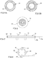
- the optical fiber may have a cylindrical hollow body and be in the form of a dielectric capillary, as shown in FIG. Figure 5A , or a more complex dielectric capillary with an air hole surrounded by a multilayer dielectric sheath as illustrated on the Figure 5B , or the optical fiber can to be a microstructured optical fiber of which an example of structure is illustrated on the figure 6 .
- the invention is not limited to the structure described in the figure 6 .
- the optical fiber can be replaced by any hollow core photonic dielectric structure.
- the excitation device 14 is coupled to the hollow-core optical fiber 16 and disposed outside said fiber and comprises a microwave-type applicator capable of generating on at least one portion of said hollow core optical fiber 16 a lateral excitation for producing inside the hollow core optical fiber a micro-plasma from the gaseous medium 10.
- the microwave-type applicator makes it possible to generate a surface wave whose spatial distribution is substantially tubular, coaxial with the optical fiber and whose peak of intensity is located at the level of the The interface between the plasma and the periphery of the hollow core 16.
- the surface wave propagates at this interface and generates a highly localized plasma column in a micrometric structure, without any damage to the material of said structure. would be damaged in the absence of surface wave by the plasma temperature which is of the order of 1500 ° C.
- the surface wave can propagate for several centimeters, which makes it possible to create a relatively long micropulp column.
- the frequency of the microwave applicator varies from 50 MHz to 10 6 Hz.
- lateral excitation is understood to mean that the fields generated by the excitation device 14 on the surface of the optical fiber 16 or at the level of the core of the fiber are essentially oriented parallel to the longitudinal direction 18 of the fiber (the longitudinal direction corresponding to the largest dimension of the fiber).
- This column of excited gas forms a plasma wave which in turn emits light.
- the envelope 12 which is in the form of a hollow-core optical fiber with a linear attenuation of less than 10 dB / m, an optical efficiency is obtained which is definitely higher than that obtained with an envelope under the shape of a simple tube.
- a compact gaseous medium 10 since the portion of the fiber 16 at which lateral excitation must be applied may be less than 5 cm, with a low energy consumption since the power supplied to the exciter is less than 100 W.
- the lateral excitation can be applied over the entire periphery of the hollow-core optical fiber 16 or only on a part.
- the excitation device may be coaxial as illustrated in FIG. figure 3 or be substantially flat as illustrated on the Figures 4A, 4B, 4C .
- the excitation device 14 may be in the form of a microstrip line 20 comprising in known manner a ground plane 22, a dielectric layer 24, a conductive line 26 and a control 28 (shown schematically), the hollow-core optical fiber 16 being disposed between the ground plane 22 and the conductive line 26, perpendicularly to said conductive line 26, the control 28 being adjusted so as to obtain a maximum electric field at the core of the hollow-core optical fiber 16.
- the optical fiber 26 may be arranged parallel to the conductive line 26.
- the optical fiber 16 is arranged perpendicular to the conductive line 26 and the ground plane 22, the microstrip line comprising an orifice 29 (whose diameter is slightly greater than that of the fiber) to allow the passage of the fiber 16 and emitting a electric field parallel to the axis of the fiber 16.
- the excitation device is coaxial and is in the form of a surfatron 30 which reproduces the elements described in the patent FR-2290126 with different dimensions.
- the excitation device 30 comprises a first hollow cylindrical wall 32 with an inner diameter Dint slightly greater than the outside diameter of the fiber 16, a second hollow cylindrical wall 34 coaxial and distant from the first cylindrical wall 32 so as to delimit an annular metal enclosure 36 coaxial with the fiber 16, closed at one end by a first side wall 38 disposed in a plane perpendicular to the longitudinal direction of the fiber 16 connecting the cylindrical walls 32 and 34 and at the other end by a second side wall 40 disposed in a plane perpendicular to the longitudinal direction of the fiber, connected to the second hollow cylindrical wall 34 with a central orifice 42 whose diameter is substantially identical to Dint.
- an annular space 44 separates the end of the first hollow cylindrical wall 32 and the second side wall 40.
- the excitation device comprises a power supply (not shown) able to provide a high frequency signal excitation by a coaxial cable of which one wire is connected to a metal element 46 disposed in the metal enclosure 36 and the other to the second cylindrical wall 34.
- the metal element 46 is presented in the form of a loop as shown on the figure 3 . This loop extends in a plane containing the longitudinal direction of the fiber 16 and is U-shaped inside the metal enclosure. This geometry of the metal element makes it possible to obtain a homogeneous electric field inside the enclosure.
- the feed and the metal element disposed in the metal enclosure are not more detailed because they are known from the patent FR-2290126 .
- the excitation device 30 When applied to a hollow-core optical fiber 16, the excitation device 30 preferably has the following characteristics:
- the annular space 44 preferably has a length E ranging from 1 to 5 mm depending on the outside diameter of the fiber 16.
- the inner diameter Dint of the hollow cylindrical wall 32 must be slightly greater than the outer diameter of the fiber 16, preferably the space between the outer face of the fiber 16 and the inner face of the wall 32 must be less than 2 mm. This characteristic makes it possible to optimize the coupling of the excitation device 14 and the fiber 16 and to limit the risks of localized heating of the fiber 16.
- the length L of the enclosure 36 is determined so that the excitation device is resonant.
- the length L must be substantially equal to ⁇ / 4 + n ⁇ ⁇ / 2, n being an integer and ⁇ the excitation wavelength.
- the second side wall 40 is more or less thick.
- this wall may have a thickness of several millimeters for a localized light source or a thinnest possible thickness and of the order of 1 mm for a laser source.
- the invention is not limited to the embodiments of the excitation devices described above but covers all the excitation devices capable of generating on the surface of the hollow-core fiber or in the hollow core of the optical fiber an electric field whose component in the longitudinal direction of the fiber is sufficient to produce a plasma from the gaseous medium 10 without an element disposed therein 16.
- the electric field was generated by two electrodes arranged in the core of the fiber, it would be difficult to control the discharge over time due to an excessive accumulation of charges on the walls delimiting the hollow core of the optical fiber.
- the envelope 12 comprising the gaseous medium is not limited to the hollow-core optical fiber.
- the hollow core fiber 16 opens at one of its ends in a cavity 48, the other end being closed or opens at each of its ends in a cavity 48, 48 '.
- the gaseous medium can be introduced into the casing 12 via at least one of the cavities 48, 48 '.
- the envelope 12 containing the gaseous medium consists of a hollow core optical fiber 16 closed at each end.
- a method as described in the document can be used WO2006 / 077437 for introducing the gaseous medium at a given pressure into the hollow-core optical fiber 16.
- the excitation device of a hollow core optical fiber can be used to generate a localized light source.
- the power used is low.
- the micro-plasma 50 produced in the core of the fiber 16 is located.
- the hollow-core optical fiber 16 comprises at each end cavities 48, 48 'in the form of gas reservoirs, at least one of the two cavities comprising a transparent wall called window 52 for allow the light ray produced to exit the envelope 12, said window 52 being arranged in the extension of
- the hollow-core optical fiber 16 could comprise at each of its ends a shutter element, at least one of which is transparent for the light beam produced at the core of the fiber 16.
- the excitation device of a hollow core optical fiber can be used to generate a gas laser source. In this case, the power used is greater than for the previous application. The power is between 1 and 100 W. As illustrated on the figure 2 the plasma produced inside the fiber is distributed and extends beyond the area covered by the excitation device.
- the hollow-core optical fiber 16 comprises at each end cavities 48, 48 'in the form of gas reservoirs, the two cavities comprising a mirror 54, 54' to obtain a phenomenon of amplification, one of the mirrors 54 'being semi-reflective to allow the laser beam 56 produced by the source to exit the envelope 12, the mirrors 54, 54' being arranged in the extension of said fiber 16.
- at least one of the cavities comprises a window to enable viewing of the emitted ray 56.
- the cavities 48, 48 ' can be replaced by photonic cells.
- the hollow-core optical fiber 16 is welded at each end to a section 58 of solid fiber, one of these sections providing the function of reflecting element the other half-reflective element.
- the hollow-core optical fiber may be longer or shorter. Thus, its length can vary from 1 cm to 100 m.
- the fiber 16 may be substantially straight as illustrated in FIG. figure 7 , or be rolled up or form a loop as shown on the figure 8 .
- the laser source may comprise an excitation device 14 associated with a fiber 16 or several excitation devices 14 associated with the same fiber 16 as illustrated in FIGS. Figures 7 and 8 .
- the entire length of the fiber 16 may be subjected to excitation by means of either an excitation device which extends over its entire length or of several excitation devices distributed over its entire length. length.
- At least one of the mirrors delimiting the optical amplification cavity is not necessarily placed at one end of the hollow-core optical fiber 16. At least one of the mirrors may be remote from one of the Thus, micro-mirrors may be inserted into the hollow-core optical fiber 16 or a Bragg grating may be formed in the microstructured sheath in the case of a hollow-core microstructured optical fiber.
- the radius 56 emitted is polychromatic.
- the composition of the gaseous medium makes it possible to determine the wavelengths of the different lines obtained.
- the pressure of the gaseous medium makes it possible to favor certain lines with respect to others.
- the opto-geometric parameters of the hollow-core optical fiber 16 may make it possible to provide the frequency filter function in order to filter certain lines spectrally and to favor others.
- the fiber 16 it is possible to choose the fiber 16 according to its diameter or to adjust the power and the frequency of the waves used for the excitation of the gaseous medium for adjusting the length of the plasma and / or certain parameters of the emitted ray 56, in particular its power.
- the laser source can work well in continuous mode as pulsed.
- the advantages provided by the invention are as follows: Unlike a gas laser of the prior art, the emitted light beam is trapped in the core of the optical fiber and is guided by said fiber to the output of the source. This advantage thus makes it possible to obtain a compact laser source that does not require a complex game of optical elements to deport the light beam. Given the absence of the complex set of optical elements, the costs associated with the adjustment of said elements and their maintenance are eliminated. In addition, the fact that the radiation emitted is guided ensures that the output fiber fiber a spatial quality of beam greater than that provided by the devices of the prior art.
- the laser source is compact to the extent that the fiber 16 can be wound if necessary.
- the laser source has reduced operating costs because it does not require electrode maintenance and the power required to produce the light beam is reduced.
- the combined choices of the composition and the pressure of the gaseous medium as well as the hollow-core optical fiber 16 in particular, its opto-geometric parameters make it possible to obtain a laser source emitting thin lines that are extremely stable in frequency both in the ultraviolet, the visible and the infrared.
- the excitation device makes it possible to be able to create compact, flexible, low-cost laser light sources emitting radiation in unconventional domains such as the ultraviolet or the mid-infrared. Deep ultraviolet radiation of the order of 100 to 300 nm could be used for the design of microelectronic components obtained by photolithography.
Landscapes
- Physics & Mathematics (AREA)
- Electromagnetism (AREA)
- Engineering & Computer Science (AREA)
- Plasma & Fusion (AREA)
- Optics & Photonics (AREA)
- Spectroscopy & Molecular Physics (AREA)
- General Physics & Mathematics (AREA)
- Lasers (AREA)
Description
- La présente invention se rapporte à un dispositif d'excitation d'une colonne de gaz enfermée dans une fibre optique à coeur creux permettant d'obtenir notamment une source de lumière ou une source laser.
- Dans le domaine des sources lasers, il existe plusieurs familles :
- La première famille comprend les diodes lasers qui sont compactes et peu couteuses. Cependant, ces sources lasers sont limitées à des plages spectrales fragmentées de longueurs d'onde conventionnelles allant de 0,4 µm à 2 µm. Ce type de lasers peut être utilisé par exemple comme source de pompe pour des lasers plus encombrants tels que les lasers de type cristallin.
- La deuxième famille comprend les lasers de type cristallin ou ionique qui utilisent un milieu solide comme milieu d'émission, dopé par des ions. Ce type de lasers est relativement couteux et encombrant et les longueurs d'onde d'émission sont limitées aux transitions radiatives des ions (notamment des ions de terres rares) dopant le milieu solide et/ou au spectre d'émission du milieu solide.
- La troisième famille comprend les lasers à gaz qui visent à exciter une colonne de gaz enfermée dans un tube ou dans une cuve. Selon l'art antérieur, ce type de lasers a pour avantage de générer un faisceau émettant à des longueurs d'onde inaccessibles par les lasers solides cités ci-dessus. Notamment, les longueurs d'ondes des lasers à gaz peuvent être dans l'ultraviolet pour les lasers excimères, dans le visible pour les lasers Argon, HE-NE, dans l'infrarouge pour les lasers CO 2. Pour ce type de lasers, la longueur d'onde du faisceau généré dépend de la composition et de la pression du mélange de gaz présent dans le tube ou dans la cuve.
- Même si cette conception de laser permet d'obtenir des faisceaux avec des longueurs d'onde comprises dans un spectre large, il n'est pas pleinement satisfaisant pour deux raisons essentiellement.
- Dans un laser à gaz, la décharge électroluminescente découle d'un champ électrique longitudinal entre deux électrodes disposées à l'intérieur et à chacune des extrémités d'un tube contenant le gaz. Les électrodes placées dans le gaz tendent à se corroder et à contaminer le milieu. Par conséquent, il est nécessaire de nettoyer fréquemment ces électrodes ce qui tend à augmenter fortement les coûts d'exploitation d'un tel laser.
- Selon un deuxième inconvénient, le rayonnement émis par ce type de laser n'est pas guidé mais en espace libre. Par conséquent, il est nécessaire de prévoir un jeu complexe d'éléments optiques pour déporter le faisceau lumineux vers sa cible, ce qui conduit à des systèmes complexes et encombrants, difficiles à régler et à entretenir. Enfin, la configuration d'interaction en espace libre entre l'excitation et le gaz limite fortement l'efficacité du laser (faible rendement optique). Compte tenu des principales caractéristiques des lasers de l'art antérieur, certains besoins industriels ne sont pas satisfaits dans la mesure où il n'existe pas un laser compact et peu coûteux à la manière d'un laser à diode, susceptible d'émettre un faisceau avec une longueur d'onde non conventionnelle, notamment dans l'ultraviolet, à la manière d'un laser à gaz.
- Compte tenu de la capacité des lasers à gaz à générer des faisceaux lumineux avec des longueurs d'onde dans un large spectre, l'invention vise à proposer une source laser à gaz peu encombrante avec à la fois une réduction des coûts d'exploitation et une augmentation drastique concernant le rendement optique. Dans le domaine des plasmas, on connait un dispositif d'excitation d'une colonne de gaz enfermée dans un tube, appelé « Surfatron », sans électrodes placées à l'intérieur du tube. Un tel dispositif est notamment décrit dans le brevet
FR-2.290.126 - Selon ce document, le mélange gazeux est disposé dans un tube creux avec un diamètre minimal de 2 mm. Le dispositif d'excitation comprend une enceinte métallique, coaxiale au tube, délimitée par une première paroi cylindrique dont le diamètre intérieur est ajusté à celui du tube, une seconde paroi cylindrique espacée et coaxiale à la première paroi cylindrique et deux parois latérales. Selon une caractéristique de ce dispositif, un espace annulaire est ménagé entre la première paroi cylindrique et une paroi latérale dite fine car moins épaisse que l'autre paroi latérale. En complément de l'enceinte métallique, le dispositif d'excitation comprend un organe de couplage sous forme d'une plaque métallique disposée dans l'enceinte à proximité de la première paroi cylindrique et de l'espace annulaire. L'organe de couplage est relié à une alimentation apte à fournir un signal haute fréquence d'excitation par un câble coaxial dont un fil est relié à la plaque métallique et l'autre à la seconde paroi cylindrique.
- Selon ce document, en fournissant un signal avec une fréquence comprise entre 100 et 1500 Mhz, il est possible de créer dans l'enceinte annulaire un champ électrique dont la direction à proximité de l'espace annulaire est parallèle à l'axe du tube contenant le gaz et engendre des ondes de surface aptes, si la puissance de l'alimentation est suffisante, à ioniser le gaz contenu dans le tube.
- Selon ce document, ce type de dispositif d'excitation associé à un tube fermé à chaque extrémité contenant un gaz peut constituer une source de lumière. A son tour, cette source de lumière peut être utilisée en tant qu'excitateur d'un milieu solide pour former un laser de type ionique.
- Le dispositif décrit dans le document
FR-2.290.126 - Un autre dispositif d'excitation décrit dans le brevet
FR-2.579.855 - Selon ce document, le mélange gazeux est stocké dans un tube avec un diamètre intérieur de l'ordre de 1,5 mm et le dispositif d'excitation comprend un applicateur micro-onde susceptible de générer à l'extérieur du tube contenant le gaz des ondes de surface aptes à produire un plasma à l'intérieur du tube.
- Le dispositif décrit dans ce document répond à un objectif de l'invention à savoir fournir un dispositif d'excitation susceptible de générer un effet laser dans un milieu gazeux qui peut donc en fonction de la composition et de la pression du gaz avoir une longueur d'onde non conventionnelle.
- Cependant, le dispositif illustré dans le brevet
FR-2.579.855 FR-2.579.855 - Le document
US-2007/0280304 décrit un dispositif d'excitation d'un milieu gazeux contenu dans une enveloppe dont le diamètre est compris entre 500 et 750 µm. Le dispositif d'excitation comprend un système disposé à l'extérieur de l'enveloppe susceptible de générer un champ électromagnétique au niveau du milieu gazeux. Ce système d'excitation se présente sous la forme d'une bobine enroulée autour de l'enveloppe. Ce mode d'excitation n'offre pas de contrôle particulier sur le plasma généré. Par conséquent, ce mode de réalisation n'est pas performant car il ne comprend aucun moyen pour optimiser le couplage de l'excitation électromagnétique avec le milieu gazeux si bien que les risques de détérioration de l'enveloppe en raison des températures élevées du plasma sont très importants. - Aussi, la présente invention vise à pallier les inconvénients de l'art antérieur en proposant un dispositif d'excitation d'un milieu gazeux compact, avec une faible consommation énergétique.
- A cet effet, l'invention a pour objet un dispositif d'excitation d'un milieu gazeux contenu dans une enveloppe, ledit dispositif étant couplé à ladite enveloppe et disposé à l'extérieur de ladite enveloppe et comprenant un applicateur susceptible de générer sur au moins une portion de ladite enveloppe une excitation latérale à l'intérieur de ladite enveloppe, caractérisé en ce que l'enveloppe est une structure diélectrique photonique à coeur creux dont le coeur a un diamètre inférieur à 300 µm et en ce que l'applicateur est de type micro-onde et permet de générer une onde de surface apte à créer et confiner un micro-plasma à partir du milieu gazeux contenu dans l'enveloppe.
- Selon un autre objectif, l'invention vise à proposer une source laser à gaz compacte, dont le rayonnement généré est guidé, avec un faible coût d'exploitation.
- D'autres caractéristiques et avantages ressortiront de la description qui va suivre de l'invention, description donnée à titre d'exemple uniquement, en regard des dessins annexés sur lesquels :
- La
figure 1 est un schéma d'une source lumineuse localisée selon l'invention, - La
figure 2 est un schéma d'une source laser selon l'invention, - La
figure 3 est un schéma d'un dispositif d'excitation selon une première variante de l'invention, - La
figure 4A est un schéma d'un dispositif d'excitation selon une autre variante de l'invention, - La
figure 4B est un schéma d'un dispositif d'excitation selon une autre variante de l'invention, - La
figure 4C est un schéma d'un dispositif d'excitation selon une autre variante de l'invention, - La
figure 5A est une section d'un premier exemple de fibre utilisée pour contenir le milieu gazeux selon l'invention, - La
figure 5B est une section d'un autre exemple de fibre utilisée pour contenir le milieu gazeux selon l'invention, - La
figure 6 est une section d'un autre exemple de fibre utilisée pour contenir le milieu gazeux selon l'invention, - La
figure 7 est un schéma d'une source laser selon une autre variante de l'invention, et - La
figure 8 est un schéma d'une source laser selon une autre variante de l'invention. - Sur les
figures 1 et 2 , on a représenté un milieu gazeux 10 contenu dans une enveloppe 12 couplée à un dispositif d'excitation 14. - Pour la suite de la description, on entend par un milieu gazeux un gaz ou un mélange de plusieurs gaz, caractérisé entre autre par une composition et une pression variant de 0,01 mbar à 50 bars.
- Selon une caractéristique de l'invention, l'enveloppe 12 comprend une fibre optique à coeur creux 16. Selon un point important de l'invention, le diamètre du coeur creux de la fibre optique est inférieur à 300 µm. De préférence, le diamètre du coeur de la fibre optique varie de 1 à 200 µm. Avantageusement, l'épaisseur du pont de silice qui entoure le coeur est inférieure à 5 µm, de préférence comprise entre 100 nm et 1 µm.
- La fibre optique à coeur creux 16 se caractérise notamment par le diamètre de son coeur creux et par des paramètres opto-géométriques liés essentiellement à la nature de la gaine entourant le coeur creux.
- Selon les cas, la fibre optique peut avoir un corps creux cylindrique et se présenter sous la forme d'un capillaire diélectrique, comme illustré sur la
figure 5A , ou d'un capillaire diélectrique plus complexe avec un trou d'air entouré d'une gaine diélectrique multicouches comme illustré sur lafigure 5B , ou la fibre optique peut être une fibre optique microstructurée dont un exemple de structure est illustré sur lafigure 6 . Bien entendu, l'invention n'est pas limitée à la structure décrite sur lafigure 6 . - En variante, la fibre optique peut être remplacée par toute structure diélectrique photonique à coeur creux.
- Selon une autre caractéristique de l'invention, le dispositif d'excitation 14 est couplé à la fibre optique à coeur creux 16 et disposé à l'extérieur de ladite fibre et comprend un applicateur de type micro-onde susceptible de générer sur au moins une portion de ladite fibre optique à coeur creux 16 une excitation latérale permettant de produire à l'intérieur de la fibre optique à coeur creux un micro-plasma à partir du milieu gazeux 10.
- Selon un point important de l'invention, l'applicateur de type micro-onde permet de générer une onde de surface dont la distribution spatiale est sensiblement tubulaire, coaxiale à la fibre optique et dont le pic d'intensité est localisé au niveau de l'interface entre le plasma et le pourtour du coeur creux 16. Ainsi, l'onde de surface se propage au niveau de cette interface et génère une colonne de plasma fortement localisée dans une structure micrométrique, sans aucun dommage sur le matériau de ladite structure qui serait endommagée en l'absence d'onde de surface par la température du plasma qui est de l'ordre de 1500°C. Selon un autre avantage, l'onde de surface peut se propager sur plusieurs centimètres ce qui permet de créer une colonne de micro-plasma relativement longue.
- Selon une caractéristique de l'invention, la fréquence de l'applicateur micro-onde varie de 50 MHz à 10 6Hz.
- Pour la suite de la description, on entend par une excitation latérale que les champs générés par le dispositif d'excitation 14 à la surface de la fibre optique 16 ou au niveau du coeur de la fibre sont essentiellement orientés parallèlement à la direction longitudinale 18 de la fibre (la direction longitudinale correspondant à la plus grande dimension de la fibre).
- Grâce à cette voie d'excitation microonde, plus de 90 % de l'énergie microonde se trouvant dans l'excitateur est transférée à la colonne de gaz.
- Cette colonne de gaz excitée forme une onde plasma qui a son tour émet la lumière.
- Compte tenu de la nature de l'enveloppe 12 qui se présente sous la forme d'une fibre optique à coeur creux avec une atténuation linéique inférieure à 10 dB/m, on obtient un rendement optique nettement supérieur à celui obtenu avec une enveloppe sous la forme d'un simple tube.
- De plus, grâce à un accord optimal entre l'onde plasma et le mode guidé dans la fibre, plus de 90% de la lumière émise par le plasma est guidée par la fibre.
- La combinaison de la dimension du coeur creux de la fibre et la nature du mode d'excitation à savoir une excitation latérale produite par un applicateur microonde dont la fréquence est comprise entre 50 MHz à 10 6Hz permet d'obtenir un dispositif d'excitation d'un milieu gazeux 10 compact puisque la portion de la fibre 16 au niveau de laquelle doit être appliquée l'excitation latérale peut être inférieure à 5 cm, avec une faible consommation énergétique puisque la puissance apportée à l'excitateur est inférieure à 100 W.
- Selon les variantes, l'excitation latérale peut être appliquée sur toute la périphérie de la fibre optique à coeur creux 16 ou seulement sur une partie. Selon les cas, le dispositif d'excitation peut être coaxial comme illustré sur la
figure 3 ou être sensiblement plan comme illustré sur lesfigures 4A, 4B, 4C . Selon l'exemple illustré sur lafigure 4A , le dispositif d'excitation 14 peut se présenter sous la forme d'une ligne microruban 20 comprenant de manière connue un plan de masse 22, une couche diélectrique 24, une ligne conductrice 26 et une commande 28 (représentée de manière schématique), la fibre optique à coeur creux 16 étant disposée entre le plan de masse 22 et la ligne conductrice 26, perpendiculairement à ladite ligne conductrice 26, la commande 28 étant réglée de manière à obtenir un champ électrique maximum au niveau du coeur de la fibre optique à coeur creux 16. En variante, comme illustré sur lafigure 4B , la fibre optique 26 peut être disposée parallèlement à la ligne conductrice 26. - En variante, comme illustré sur la
figure 4C , la fibre optique 16 est disposée perpendiculairement à la ligne conductrice 26 et au plan masse 22, la ligne microruban comprenant un orifice 29 (dont le diamètre est légèrement supérieur à celui de la fibre) pour permettre le passage de la fibre 16 et émettant un champ électrique parallèle à l'axe de la fibre 16. - Selon un autre mode de réalisation illustré sur la
figure 3 , le dispositif de d'excitation est coaxial et se présente sous la forme d'un surfatron 30 qui reproduit les éléments décrits dans le brevetFR-2.290.126 - Ainsi, le dispositif d'excitation 30 comprend une première paroi cylindrique creuse 32 avec un diamètre intérieur Dint légèrement supérieur au diamètre extérieur dext de la fibre 16, une seconde paroi cylindrique creuse 34 coaxiale et distante de la première paroi cylindrique 32 de manière à délimiter une enceinte métallique 36 annulaire coaxiale à la fibre 16, fermée à une première extrémité par une première paroi latérale 38 disposée dans un plan perpendiculaire à la direction longitudinale de la fibre 16 reliant les parois cylindriques 32 et 34 et à l'autre extrémité par une seconde paroi latérale 40 disposée dans un plan perpendiculaire à la direction longitudinale de la fibre, reliée à la seconde paroi cylindrique creuse 34 avec un orifice 42 central dont le diamètre est sensiblement identique à Dint. Selon un point important, un espace annulaire 44 sépare l'extrémité de la première paroi cylindrique creuse 32 et la seconde paroi latérale 40. En complément, le dispositif d'excitation comprend une alimentation (non représentée) apte à fournir un signal haute fréquence d'excitation par un câble coaxial dont un fil est relié à un élément métallique 46 disposé dans l'enceinte métallique 36 et l'autre à la seconde paroi cylindrique 34. Selon une caractéristique de l'invention, l'élément métallique 46 se présente sous forme d'une boucle comme illustré sur la
figure 3 . Cette boucle s'étend dans un plan contenant la direction longitudinale de la fibre 16 et a une forme en U à l'intérieur de l'enceinte métallique. Cette géométrie de l'élément métallique permet d'obtenir un champ électrique homogène à l'intérieur de l'enceinte. L'alimentation et l'élément métallique disposé dans l'enceinte métallique ne sont pas plus détaillés car ils sont connus du brevetFR-2.290.126 - Appliqué à une fibre optique à coeur creux 16, le dispositif d'excitation 30 a de préférence les caractéristiques suivantes :
L'espace annulaire 44 a de préférence une longueur E variant de 1 à 5 mm en fonction du diamètre extérieur de la fibre 16. - Le diamètre intérieur Dint de la paroi cylindrique creuse 32 doit être légèrement supérieur au diamètre extérieur de la fibre 16, de préférence l'espace entre la face extérieure de la fibre 16 et la face intérieure de la paroi 32 doit être inférieur à 2 mm. Cette caractéristique permet d'optimiser le couplage du dispositif d'excitation 14 et de la fibre 16 et de limiter les risques d'échauffement localisé de la fibre 16.
- Selon un autre aspect, la longueur L de l'enceinte 36 est déterminée pour que le dispositif d'excitation soit résonant. Ainsi la longueur L doit être sensiblement égale à λ/4+n×λ/2, n étant un entier et λ la longueur d'onde d'excitation.
- Selon les applications, la seconde paroi latérale 40 est plus ou moins épaisse. Ainsi, cette paroi peut avoir une épaisseur de plusieurs millimètres pour une source de lumière localisée ou une épaisseur la plus fine possible et de l'ordre de 1 mm pour une source laser.
- L'invention n'est pas limitée aux modes de réalisation des dispositifs d'excitation décrits ci-dessus mais couvre tous les dispositifs d'excitation susceptibles de générer en surface de la fibre à coeur creux ou dans le coeur creux de la fibre optique un champ électrique dont la composante selon la direction longitudinale de la fibre est suffisante pour produire un plasma à partir du milieu gazeux 10 sans élément disposé à l'intérieur de la fibre 16. En effet, dans le cas contraire à savoir si le champ électrique était généré par deux électrodes disposées dans le coeur de la fibre, il serait difficile de contrôler la décharge au cours du temps en raison d'une accumulation excessive de charges sur les parois délimitant le coeur creux de la fibre optique.
- Selon une première variante illustrée sur les
figures 1 et 2 , l'enveloppe 12 comprenant le milieu gazeux n'est pas limitée à la fibre optique à coeur creux. Dans ce cas, la fibre à coeur creux 16 débouche à une de ses extrémités dans une cavité 48, l'autre extrémité étant obturée ou débouche à chacune de ses extrémités dans une cavité 48, 48'. Dans ce cas, le milieu gazeux peut être introduit dans l'enveloppe 12 via au moins une des cavités 48, 48'. - Selon une autre variante illustrée sur les
figures 7 et 8 , l'enveloppe 12 contenant le milieu gazeux est constituée d'une fibre optique à coeur creux 16 obturée à chaque extrémité. Dans ce cas, on peut utiliser une méthode telle que décrite dans le documentWO2006/077437 pour introduire le milieu gazeux à une pression donnée dans la fibre optique à coeur creux 16. - Selon une première application illustrée sur la
figure 1 , le dispositif d'excitation d'une fibre optique à coeur creux peut être utilisé pour générer une source lumineuse localisée. Dans ce cas, la puissance utilisée est faible. Comme illustré sur lafigure 1 , le micro-plasma 50 produit dans le coeur de la fibre 16 est localisé. - Selon un mode de réalisation décrit pour cette application, la fibre optique à coeur creux 16 comprend à chaque extrémité des cavités 48, 48' sous forme de réservoirs à gaz, au moins l'une des deux cavités comprenant une paroi transparente appelée fenêtre 52 pour permettre au rayon lumineux produit de sortir de l'enveloppe 12, ladite fenêtre 52 étant disposée dans le prolongement de ladite fibre 16. En variante, la fibre optique à coeur creux 16 pourrait comprendre à chacune de ses extrémités un élément obturateur dont au moins un est transparent pour le rayon lumineux produit au niveau du coeur de la fibre 16. Selon une autre application illustrée sur les
figures 2 ,7 et 8 , le dispositif d'excitation d'une fibre optique à coeur creux peut être utilisé pour générer une source laser à gaz. Dans ce cas, la puissance utilisée est plus importante que pour l'application précédente. La puissance est comprise entre 1 et 100 W. Comme illustré sur lafigure 2 , le plasma produit à l'intérieur de la fibre est distribué et s'étend au-delà de la zone couverte par le dispositif d'excitation. - Selon un mode de réalisation décrit pour cette application, la fibre optique à coeur creux 16 comprend à chaque extrémité des cavités 48, 48' sous forme de réservoirs à gaz, les deux cavités comprenant un miroir 54, 54' pour obtenir un phénomène d'amplification, l'un des miroirs 54' étant semi-réfléchissant pour permettre au rayon laser 56 produit par la source de sortir de l'enveloppe 12, les miroirs 54, 54' étant disposés dans le prolongement de ladite fibre 16. Les cavités 48 et 48' peuvent être utilisées pour introduire le milieu gazeux dans l'enveloppe, pour la vidanger ou contrôler la pression du milieu gazeux. A cet effet, les cavités 48 et 48' peuvent être équipées de vannes et de manomètres. De préférence, au moins l'une des cavités comprend une fenêtre pour permettre de visualiser le rayon 56 émis.
- En variante, les cavités 48, 48' peuvent être remplacées par des cellules photoniques. Dans ce cas, la fibre optique à coeur creux 16 est soudée à chaque extrémité à un tronçon 58 de fibre pleine, l'un de ces tronçons assurant la fonction d'élément réfléchissant l'autre d'élément semi-réfléchissant.
- Selon les besoins, la fibre optique à coeur creux peut être plus ou moins longue. Ainsi, sa longueur peut varier de 1 cm à 100 m.
- En fonction de la compacité recherchée, la fibre 16 peut être sensiblement rectiligne comme illustré sur la
figure 7 , ou être enroulée ou former une boucle comme illustré sur lafigure 8 . - Selon les cas, la source laser peut comprendre un dispositif d'excitation 14 associé à une fibre 16 ou plusieurs dispositifs d'excitation 14 associés à une même fibre 16 comme illustré sur les
figures 7 et 8 . Selon une variante ultime, toute la longueur de la fibre 16 peut être soumise à une excitation par l'intermédiaire soit d'un dispositif d'excitation qui s'étend sur toute sa longueur ou soit de plusieurs dispositifs d'excitation répartis sur toute sa longueur. - Selon un autre agencement, au moins un des miroirs délimitant la cavité optique d'amplification n'est pas nécessairement placé à l'une des extrémités de la fibre optique à coeur creux 16. Au moins un des miroirs peut être distant d'une des extrémités de la fibre optique 16. Ainsi des micro-miroirs peuvent être insérés dans la fibre optique à coeur creux 16 ou un réseau de Bragg peut être formé dans la gaine microstructurée dans le cas d'une fibre optique microstructurée à coeur creux.
- Sur le plan structurel, il est possible de prévoir un ou des systèmes de refroidissement pour refroidir la fibre 16 au niveau du ou des dispositifs d'excitation 14.
- Sur le plan fonctionnel, le rayon 56 émis est polychromatique. La composition du milieu gazeux permet de déterminer les longueurs d'onde des différentes raies obtenues. La pression du milieu gazeux permet de favoriser certaines raies par rapport à d'autres. Les paramètres opto-géométriques de la fibre optique à coeur creux 16 peuvent permettre d'assurer la fonction de filtre fréquentiel afin de filtrer spectralement certaines raies et d'en favoriser d'autres.
- En outre, il est possible de choisir la fibre 16 en fonction de son diamètre ou d'ajuster la puissance et la fréquence des ondes utilisées pour l'excitation du milieu gazeux pour ajuster la longueur du plasma et/ou certains paramètres du rayon émis 56, notamment sa puissance.
- Enfin, la source laser peut aussi bien fonctionner en régime continu qu'en régime pulsé.
- Sur le plan expérimental, en choisissant un capillaire diélectrique avec un coeur creux de 107 µm de diamètre comme fibre 16, de l'argon comme milieu gazeux avec une pression de 3 bars et une puissance d'excitation de 47 W avec une fréquence de 2,45 GHz, il est possible d'observer un plasma relativement stable. Avec une puissance d'excitation de 35 W et une pression de 2,8 bars, la puissance optique du faisceau lumineux est de l'ordre de 5 mW et on obtient un faisceau quasi-monomode.
- Les avantages procurés par l'invention sont les suivants :
Contrairement à un laser à gaz de l'art antérieur, le faisceau lumineux émis est piégé dans le coeur de la fibre optique et se trouve guidé par ladite fibre jusqu'à la sortie de la source. Cet avantage permet ainsi d'obtenir une source laser compacte ne nécessitant pas un jeu complexe d'éléments optiques pour déporter le faisceau lumineux. Compte tenu de l'absence du jeu complexe d'éléments optiques, les coûts liés au réglage desdits éléments et à leurs entretiens sont supprimés. De plus, le fait que le rayonnement émis soit guidé assure en sortie de fibre une qualité spatiale de faisceau supérieure à celle procurée par les dispositifs de l'art antérieur. - Selon un autre aspect, la source laser est compacte dans la mesure où la fibre 16 peut s'enrouler si nécessaire.
- Selon un autre aspect, la source laser a des coûts d'exploitation réduits compte tenu du fait qu'elle ne nécessite pas d'entretien d'électrodes et que la puissance requise pour produire le faisceau lumineux est réduit.
- Enfin, selon un autre aspect, les choix combinés de la composition et de la pression du milieu gazeux ainsi que de la fibre optique à coeur creux 16 en fonction notamment de ses paramètres opto-géométriques permettent d'obtenir une source laser émettant des raies fines et extrêmement stables en fréquence aussi bien dans l'ultraviolet, le visible que l'infrarouge.
- Le dispositif d'excitation selon l'invention permet de pouvoir créer des sources lumineuses lasers compactes, flexibles, à bas coût, émettant un rayonnement dans les domaines non conventionnels comme l'ultraviolet ou l'infrarouge moyen. Un rayonnement ultraviolet profond de l'ordre de 100 à 300 nm pourrait être utilisé pour la conception de composants micro-électroniques obtenus par photolithographie.
- Toutefois, d'autres applications pourraient être envisagées comme par exemple le traitement des eaux usées, l'ablation de certains tissus ou le remodelage de la rétine dans le domaine médical.
Claims (18)
- Ensemble comprenant une enveloppe (12) contenant un milieu gazeux (10) et un dispositif d'excitation (14) du milieu gazeux (10) contenu dans l'enveloppe (12), ledit dispositif étant couplé à ladite enveloppe (12) et disposé à l'extérieur de ladite enveloppe (12) et comprenant un applicateur susceptible de générer sur au moins une portion de ladite enveloppe (12) une excitation latérale à l'intérieur de ladite enveloppe (12), caractérisé en ce que l'enveloppe (12) est une fibre optique à coeur creux (16) dont le coeur a un diamètre inférieur à 300 µm et en ce que l'applicateur est de type micro-onde et permet de générer une onde de surface apte à créer et confiner un micro-plasma à partir du milieu gazeux contenu dans l'enveloppe (12).
- Ensemble selon la revendication 1, caractérisé en ce que le diamètre du coeur creux (16) varie de 1 à 200 µm.
- Ensemble selon la revendication 1 ou 2, caractérisé en ce que l'enveloppe (12) présente une atténuation linéique inférieure à 10 dB/m.
- Ensemble selon l'une quelconque des revendications précédentes, caractérisé en ce que l'applicateur micro-onde se présente sous la forme d'une ligne microruban (20) comprenant un plan de masse (22), une couche diélectrique (24), une ligne conductrice (26), la fibre optique à coeur creux (16) étant disposée entre le plan de masse (22) et la ligne conductrice (26).
- Ensemble selon l'une quelconque des revendications 1 à 3, caractérisé en ce que l'applicateur micro-onde comprend une enceinte métallique (36) annulaire coaxiale à la fibre (16) avec un espace annulaire (44) et une alimentation apte à fournir un signal haute fréquence d'excitation comportant un élément métallique (46) disposé dans l'enceinte métallique (36).
- Ensemble selon la revendication 5, caractérisé en ce que l'élément métallique (46) se présente sous la forme d'une boucle.
- Ensemble selon la revendication 6, caractérisé en ce que la boucle s'étend dans un plan contenant la direction longitudinale de la fibre (16) et a une forme en U à l'intérieur de l'enceinte métallique.
- Ensemble selon l'une quelconque des revendications 5 à 7, caractérisé en ce que l'espace annulaire (44) a une longueur variant de 1 à 5 mm.
- Ensemble selon l'une quelconque des revendications 5 à 8, caractérisé en ce que l'enceinte métallique (36) annulaire est délimitée par une première paroi cylindrique creuse (32) dont le diamètre intérieur est légèrement supérieur au diamètre extérieur de la fibre (16).
- Ensemble selon l'une quelconque des revendications précédentes, caractérisé en ce que l'enveloppe (12) comprend une fibre optique (16) à coeur creux et au moins une cavité (48) prévue à au moins une des extrémités de ladite fibre (16).
- Ensemble selon l'une quelconque des revendications précédentes, caractérisé en ce que l'enveloppe (12) est constituée d'une fibre optique (16) obturée à chaque extrémité.
- Source de lumière comprenant un ensemble selon l'une quelconque des revendications précédentes.
- Source laser comprenant un ensemble selon l'une quelconque des revendications 1 à 11.
- Source laser selon la revendication 13, caractérisée en ce que la fibre optique à coeur creux (16) est soudée à chaque extrémité à un tronçon (58) de fibre pleine, l'un de ces tronçons assurant la fonction d'élément réfléchissant l'autre d'élément semi-réfléchissant.
- Source laser selon la revendication 14, caractérisée en ce qu'au moins un des miroirs délimitant la cavité optique est distant de l'extrémité de la fibre optique (16) à coeur creux.
- Source laser selon l'une quelconque des revendications 13 à 15, caractérisée en ce que la fibre optique à coeur creux (16) est une fibre optique microstructurée.
- Source laser selon l'une quelconque des revendications 13 à 15, caractérisée en ce que la fibre optique à coeur creux (16) est un capillaire diélectrique avec un trou d'air entouré d'une gaine diélectrique multicouches.
- Procédé d'émission d'un faisceau laser à partir d'une source laser selon l'une quelconque des revendications 13 à 17, caractérisé en ce qu'il consiste à utiliser les paramètres opto-géométriques de la fibre optique (16) à coeur creux pour assurer la fonction de filtre fréquentiel.
Applications Claiming Priority (2)
| Application Number | Priority Date | Filing Date | Title |
|---|---|---|---|
| FR1153677A FR2974680B1 (fr) | 2011-04-29 | 2011-04-29 | Dispositif d'excitation d'une colonne de gaz enfermee dans une fibre optique a coeur creux |
| PCT/FR2012/050927 WO2012146874A1 (fr) | 2011-04-29 | 2012-04-26 | Dispositif d'excitation d'une colonne de gaz enfermee dans une fibre optique a cœur creux |
Publications (2)
| Publication Number | Publication Date |
|---|---|
| EP2702650A1 EP2702650A1 (fr) | 2014-03-05 |
| EP2702650B1 true EP2702650B1 (fr) | 2018-08-15 |
Family
ID=46201683
Family Applications (1)
| Application Number | Title | Priority Date | Filing Date |
|---|---|---|---|
| EP12725058.7A Active EP2702650B1 (fr) | 2011-04-29 | 2012-04-26 | Dispositif d'excitation d'une colonne de gaz enfermee dans une fibre optique a coeur creux |
Country Status (5)
| Country | Link |
|---|---|
| US (1) | US9203203B2 (fr) |
| EP (1) | EP2702650B1 (fr) |
| FR (1) | FR2974680B1 (fr) |
| TW (1) | TW201304331A (fr) |
| WO (1) | WO2012146874A1 (fr) |
Families Citing this family (20)
| Publication number | Priority date | Publication date | Assignee | Title |
|---|---|---|---|---|
| WO2011142849A2 (fr) * | 2010-01-21 | 2011-11-17 | Rudolph Wolfgang G | Laser à fibre creuse remplie de gaz |
| FR2974680B1 (fr) * | 2011-04-29 | 2014-04-11 | Univ Limoges | Dispositif d'excitation d'une colonne de gaz enfermee dans une fibre optique a coeur creux |
| CN103078239B (zh) * | 2012-12-27 | 2015-06-24 | 中国科学院安徽光学精密机械研究所 | 一种微波激励气体的装置及方法 |
| US9372299B1 (en) * | 2014-02-19 | 2016-06-21 | The United States Of America As Represented By The Administrator Of The National Aeronautics And Space Administration | Hollow-core fiber lamp |
| KR101558737B1 (ko) | 2014-02-21 | 2015-10-08 | 한국원자력연구원 | 광학 공동 비축을 이용한 빔 정렬 장치 및 방법 |
| CN104577683A (zh) * | 2015-01-12 | 2015-04-29 | 中国科学院合肥物质科学研究院 | 一种空芯光子晶体光纤气体激光器的谐振腔 |
| FR3039289A1 (fr) * | 2015-07-22 | 2017-01-27 | Thales Sa | Terminaison pour fibre optique a coeur creux |
| CN110068551A (zh) * | 2019-06-04 | 2019-07-30 | 中国计量大学 | 一种对称级联结构光纤spr检测器 |
| US11128097B2 (en) * | 2019-08-02 | 2021-09-21 | Samsung Electronics Co., Ltd. | Light source apparatus |
| US20210057864A1 (en) * | 2019-08-19 | 2021-02-25 | Iradion Laser, Inc. | Enhanced waveguide surface in gas lasers |
| CN114079219B (zh) * | 2020-08-12 | 2024-04-26 | 中国科学院大连化学物理研究所 | 带有金属涂层的空芯光子晶体光纤与高压气室密封结构 |
| WO2022087743A1 (fr) * | 2020-10-30 | 2022-05-05 | Quantum Valley Ideas Laboratories | Masers à cristal photonique |
| CN113219588B (zh) * | 2021-07-08 | 2021-09-14 | 武汉聚合光子技术有限公司 | 一种光纤合束器的制作方法及装置 |
| CN114205980A (zh) * | 2021-11-11 | 2022-03-18 | 中国人民解放军空军工程大学 | 一种提升duv光源的波段选择性的产生方法 |
| US11469566B1 (en) | 2022-02-08 | 2022-10-11 | Quantum Valley Ideas Laboratories | Generating electromagnetic radiation from a photonic crystal maser |
| US11533101B1 (en) | 2022-02-08 | 2022-12-20 | Quantum Valley Ideas Laboratories | Communicating information using photonic crystal masers |
| US11402479B1 (en) | 2022-02-08 | 2022-08-02 | Quantum Valley Ideas Laboratories | Communicating information using photonic crystal transceivers |
| CN115185036B (zh) * | 2022-07-18 | 2024-03-01 | 江苏师范大学 | 一种基于气体顺磁效应的空芯光纤光栅及实现方法 |
| CN116908971B (zh) * | 2023-06-27 | 2025-11-11 | 深圳综合粒子设施研究院 | 一种光路耦合设备 |
| CN119920518A (zh) * | 2025-01-14 | 2025-05-02 | 浙江大学 | 空芯光纤约束气体激发收集方法及装置 |
Family Cites Families (9)
| Publication number | Priority date | Publication date | Assignee | Title |
|---|---|---|---|---|
| US3493845A (en) * | 1965-06-04 | 1970-02-03 | Melpar Inc | Coherent light source utilizing microwave pumping of an element having a metastable state as its first excited level |
| FR2290126A1 (fr) * | 1974-10-31 | 1976-05-28 | Anvar | Perfectionnements apportes aux dispositifs d'excitation, par des ondes hf, d'une colonne de gaz enfermee dans une enveloppe |
| FR2579855A1 (fr) | 1985-03-28 | 1986-10-03 | Centre Nat Rech Scient | Dispositif pour l'excitation par ondes hyperfrequences d'un plasma dans une colonne de gaz, permettant notamment la realisation d'un laser ionique |
| JPS6249683A (ja) * | 1985-08-27 | 1987-03-04 | Mitsubishi Electric Corp | ガスレ−ザ装置 |
| US5359621A (en) * | 1993-05-11 | 1994-10-25 | General Atomics | High efficiency gas laser with axial magnetic field and tunable microwave resonant cavity |
| GB9323601D0 (en) * | 1993-11-16 | 1994-01-05 | Atomic Energy Authority Uk | Plasma light source |
| GB0501493D0 (en) | 2005-01-24 | 2005-03-02 | Univ Bath | An optical assembly and method |
| US20070280304A1 (en) * | 2006-06-05 | 2007-12-06 | Jochen Deile | Hollow Core Fiber Laser |
| FR2974680B1 (fr) * | 2011-04-29 | 2014-04-11 | Univ Limoges | Dispositif d'excitation d'une colonne de gaz enfermee dans une fibre optique a coeur creux |
-
2011
- 2011-04-29 FR FR1153677A patent/FR2974680B1/fr not_active Expired - Fee Related
-
2012
- 2012-04-26 EP EP12725058.7A patent/EP2702650B1/fr active Active
- 2012-04-26 US US14/114,621 patent/US9203203B2/en active Active
- 2012-04-26 WO PCT/FR2012/050927 patent/WO2012146874A1/fr not_active Ceased
- 2012-04-27 TW TW101115134A patent/TW201304331A/zh unknown
Also Published As
| Publication number | Publication date |
|---|---|
| EP2702650A1 (fr) | 2014-03-05 |
| FR2974680B1 (fr) | 2014-04-11 |
| US20140048410A1 (en) | 2014-02-20 |
| FR2974680A1 (fr) | 2012-11-02 |
| WO2012146874A1 (fr) | 2012-11-01 |
| TW201304331A (zh) | 2013-01-16 |
| US9203203B2 (en) | 2015-12-01 |
Similar Documents
| Publication | Publication Date | Title |
|---|---|---|
| EP2702650A1 (fr) | Dispositif d'excitation d'une colonne de gaz enfermee dans une fibre optique a c ur creux | |
| EP0197843B1 (fr) | Dispositif pour l'excitation par ondes hyperfréquences d'un plasma dans une colonne de gaz, permettant notamment la réalisation d'un laser ionique | |
| CN101861684A (zh) | 激光光源和用于操作激光光源的方法 | |
| EP1518256B1 (fr) | Dispositif de production d'une nappe de plasma | |
| WO2019233900A1 (fr) | Procédés et systèmes pour la génération d'impulsions laser de forte puissance crête | |
| EP3338330B1 (fr) | Laser térahertz, source térahertz et utilisation d'un tel laser térahertz | |
| EP3804052A1 (fr) | Procédés et systèmes pour la génération d'impulsions laser de forte puissance crête | |
| EP2497165B1 (fr) | Source optique mettant en oeuvre une fibre dopee, fibre pour une telle source optique et procede de fabrication d'une telle fibre. | |
| EP2700133B1 (fr) | Dispostif laser d'emission d'ondes dans le domaine des terahertz | |
| EP0751594B1 (fr) | Cavité microlaser et microlaser solide impulsionnel à déclenchement actif par micromodulateur | |
| EP2018687B1 (fr) | Dispositif laser impulsionnel a fibre optique de forte puissance | |
| EP2041848B1 (fr) | Dispositif laser à fibre optique de puissance | |
| CA2827445C (fr) | Laser a fibre optique de forte puissance | |
| EP4348776B1 (fr) | Oscillateur laser a impulsions ultra-courtes de type mamyshev et son dispositif de demarrage | |
| FR2691588A1 (fr) | Source laser de puissance. | |
| EP1966856B1 (fr) | Dispositif a guide optique destine a produire un signal optique par pompage optique et applications de ce dispositif | |
| EP2439820B1 (fr) | Procédé de génération d'un rayonnement laser de courte durée, de moins de 100ns, à une cadence élevée, de plus de 50kHz | |
| EP2443705B1 (fr) | Système d'émission d'une lumière polychromatique a sous-cavités couplées | |
| EP3082203A1 (fr) | Systeme d'emission laser impulsionnelle accordable | |
| FR2800926A1 (fr) | Laser a fibre de puissance emettant un rayonnement monomode transverse centre vers 980 nm |
Legal Events
| Date | Code | Title | Description |
|---|---|---|---|
| PUAI | Public reference made under article 153(3) epc to a published international application that has entered the european phase |
Free format text: ORIGINAL CODE: 0009012 |
|
| 17P | Request for examination filed |
Effective date: 20131024 |
|
| AK | Designated contracting states |
Kind code of ref document: A1 Designated state(s): AL AT BE BG CH CY CZ DE DK EE ES FI FR GB GR HR HU IE IS IT LI LT LU LV MC MK MT NL NO PL PT RO RS SE SI SK SM TR |
|
| DAX | Request for extension of the european patent (deleted) | ||
| STAA | Information on the status of an ep patent application or granted ep patent |
Free format text: STATUS: EXAMINATION IS IN PROGRESS |
|
| 17Q | First examination report despatched |
Effective date: 20170227 |
|
| RIC1 | Information provided on ipc code assigned before grant |
Ipc: H01J 65/04 20060101ALI20180131BHEP Ipc: H01S 3/22 20060101ALI20180131BHEP Ipc: H01S 1/06 20060101ALI20180131BHEP Ipc: H05H 1/46 20060101ALI20180131BHEP Ipc: H01S 3/0975 20060101AFI20180131BHEP Ipc: H01S 3/032 20060101ALI20180131BHEP Ipc: G02B 6/02 20060101ALI20180131BHEP Ipc: H01S 3/067 20060101ALI20180131BHEP |
|
| GRAP | Despatch of communication of intention to grant a patent |
Free format text: ORIGINAL CODE: EPIDOSNIGR1 |
|
| STAA | Information on the status of an ep patent application or granted ep patent |
Free format text: STATUS: GRANT OF PATENT IS INTENDED |
|
| INTG | Intention to grant announced |
Effective date: 20180314 |
|
| RIN1 | Information on inventor provided before grant (corrected) |
Inventor name: GEROME, FREDERIC Inventor name: BLONDY, JEAN-MARC Inventor name: BENABID, FETAH Inventor name: LEPRINCE, PHILIPPE Inventor name: JAMIER, RAPHAEL Inventor name: DEBORD, BENOIT |
|
| GRAS | Grant fee paid |
Free format text: ORIGINAL CODE: EPIDOSNIGR3 |
|
| GRAA | (expected) grant |
Free format text: ORIGINAL CODE: 0009210 |
|
| STAA | Information on the status of an ep patent application or granted ep patent |
Free format text: STATUS: THE PATENT HAS BEEN GRANTED |
|
| AK | Designated contracting states |
Kind code of ref document: B1 Designated state(s): AL AT BE BG CH CY CZ DE DK EE ES FI FR GB GR HR HU IE IS IT LI LT LU LV MC MK MT NL NO PL PT RO RS SE SI SK SM TR |
|
| REG | Reference to a national code |
Ref country code: CH Ref legal event code: EP Ref country code: GB Ref legal event code: FG4D Free format text: NOT ENGLISH Ref country code: AT Ref legal event code: REF Ref document number: 1030868 Country of ref document: AT Kind code of ref document: T Effective date: 20180815 |
|
| REG | Reference to a national code |
Ref country code: IE Ref legal event code: FG4D Free format text: LANGUAGE OF EP DOCUMENT: FRENCH |
|
| REG | Reference to a national code |
Ref country code: DE Ref legal event code: R096 Ref document number: 602012049786 Country of ref document: DE |
|
| REG | Reference to a national code |
Ref country code: NL Ref legal event code: MP Effective date: 20180815 |
|
| REG | Reference to a national code |
Ref country code: LT Ref legal event code: MG4D |
|
| REG | Reference to a national code |
Ref country code: AT Ref legal event code: MK05 Ref document number: 1030868 Country of ref document: AT Kind code of ref document: T Effective date: 20180815 Ref country code: CH Ref legal event code: NV Representative=s name: BUGNION S.A., CH |
|
| PG25 | Lapsed in a contracting state [announced via postgrant information from national office to epo] |
Ref country code: FI Free format text: LAPSE BECAUSE OF FAILURE TO SUBMIT A TRANSLATION OF THE DESCRIPTION OR TO PAY THE FEE WITHIN THE PRESCRIBED TIME-LIMIT Effective date: 20180815 Ref country code: IS Free format text: LAPSE BECAUSE OF FAILURE TO SUBMIT A TRANSLATION OF THE DESCRIPTION OR TO PAY THE FEE WITHIN THE PRESCRIBED TIME-LIMIT Effective date: 20181215 Ref country code: RS Free format text: LAPSE BECAUSE OF FAILURE TO SUBMIT A TRANSLATION OF THE DESCRIPTION OR TO PAY THE FEE WITHIN THE PRESCRIBED TIME-LIMIT Effective date: 20180815 Ref country code: AT Free format text: LAPSE BECAUSE OF FAILURE TO SUBMIT A TRANSLATION OF THE DESCRIPTION OR TO PAY THE FEE WITHIN THE PRESCRIBED TIME-LIMIT Effective date: 20180815 Ref country code: GR Free format text: LAPSE BECAUSE OF FAILURE TO SUBMIT A TRANSLATION OF THE DESCRIPTION OR TO PAY THE FEE WITHIN THE PRESCRIBED TIME-LIMIT Effective date: 20181116 Ref country code: NO Free format text: LAPSE BECAUSE OF FAILURE TO SUBMIT A TRANSLATION OF THE DESCRIPTION OR TO PAY THE FEE WITHIN THE PRESCRIBED TIME-LIMIT Effective date: 20181115 Ref country code: BG Free format text: LAPSE BECAUSE OF FAILURE TO SUBMIT A TRANSLATION OF THE DESCRIPTION OR TO PAY THE FEE WITHIN THE PRESCRIBED TIME-LIMIT Effective date: 20181115 Ref country code: SE Free format text: LAPSE BECAUSE OF FAILURE TO SUBMIT A TRANSLATION OF THE DESCRIPTION OR TO PAY THE FEE WITHIN THE PRESCRIBED TIME-LIMIT Effective date: 20180815 Ref country code: NL Free format text: LAPSE BECAUSE OF FAILURE TO SUBMIT A TRANSLATION OF THE DESCRIPTION OR TO PAY THE FEE WITHIN THE PRESCRIBED TIME-LIMIT Effective date: 20180815 Ref country code: LT Free format text: LAPSE BECAUSE OF FAILURE TO SUBMIT A TRANSLATION OF THE DESCRIPTION OR TO PAY THE FEE WITHIN THE PRESCRIBED TIME-LIMIT Effective date: 20180815 |
|
| PG25 | Lapsed in a contracting state [announced via postgrant information from national office to epo] |
Ref country code: HR Free format text: LAPSE BECAUSE OF FAILURE TO SUBMIT A TRANSLATION OF THE DESCRIPTION OR TO PAY THE FEE WITHIN THE PRESCRIBED TIME-LIMIT Effective date: 20180815 Ref country code: LV Free format text: LAPSE BECAUSE OF FAILURE TO SUBMIT A TRANSLATION OF THE DESCRIPTION OR TO PAY THE FEE WITHIN THE PRESCRIBED TIME-LIMIT Effective date: 20180815 Ref country code: AL Free format text: LAPSE BECAUSE OF FAILURE TO SUBMIT A TRANSLATION OF THE DESCRIPTION OR TO PAY THE FEE WITHIN THE PRESCRIBED TIME-LIMIT Effective date: 20180815 |
|
| PG25 | Lapsed in a contracting state [announced via postgrant information from national office to epo] |
Ref country code: ES Free format text: LAPSE BECAUSE OF FAILURE TO SUBMIT A TRANSLATION OF THE DESCRIPTION OR TO PAY THE FEE WITHIN THE PRESCRIBED TIME-LIMIT Effective date: 20180815 Ref country code: CZ Free format text: LAPSE BECAUSE OF FAILURE TO SUBMIT A TRANSLATION OF THE DESCRIPTION OR TO PAY THE FEE WITHIN THE PRESCRIBED TIME-LIMIT Effective date: 20180815 Ref country code: PL Free format text: LAPSE BECAUSE OF FAILURE TO SUBMIT A TRANSLATION OF THE DESCRIPTION OR TO PAY THE FEE WITHIN THE PRESCRIBED TIME-LIMIT Effective date: 20180815 Ref country code: RO Free format text: LAPSE BECAUSE OF FAILURE TO SUBMIT A TRANSLATION OF THE DESCRIPTION OR TO PAY THE FEE WITHIN THE PRESCRIBED TIME-LIMIT Effective date: 20180815 Ref country code: IT Free format text: LAPSE BECAUSE OF FAILURE TO SUBMIT A TRANSLATION OF THE DESCRIPTION OR TO PAY THE FEE WITHIN THE PRESCRIBED TIME-LIMIT Effective date: 20180815 Ref country code: EE Free format text: LAPSE BECAUSE OF FAILURE TO SUBMIT A TRANSLATION OF THE DESCRIPTION OR TO PAY THE FEE WITHIN THE PRESCRIBED TIME-LIMIT Effective date: 20180815 |
|
| REG | Reference to a national code |
Ref country code: DE Ref legal event code: R097 Ref document number: 602012049786 Country of ref document: DE |
|
| PG25 | Lapsed in a contracting state [announced via postgrant information from national office to epo] |
Ref country code: SM Free format text: LAPSE BECAUSE OF FAILURE TO SUBMIT A TRANSLATION OF THE DESCRIPTION OR TO PAY THE FEE WITHIN THE PRESCRIBED TIME-LIMIT Effective date: 20180815 Ref country code: DK Free format text: LAPSE BECAUSE OF FAILURE TO SUBMIT A TRANSLATION OF THE DESCRIPTION OR TO PAY THE FEE WITHIN THE PRESCRIBED TIME-LIMIT Effective date: 20180815 Ref country code: SK Free format text: LAPSE BECAUSE OF FAILURE TO SUBMIT A TRANSLATION OF THE DESCRIPTION OR TO PAY THE FEE WITHIN THE PRESCRIBED TIME-LIMIT Effective date: 20180815 |
|
| PLBE | No opposition filed within time limit |
Free format text: ORIGINAL CODE: 0009261 |
|
| STAA | Information on the status of an ep patent application or granted ep patent |
Free format text: STATUS: NO OPPOSITION FILED WITHIN TIME LIMIT |
|
| 26N | No opposition filed |
Effective date: 20190516 |
|
| PG25 | Lapsed in a contracting state [announced via postgrant information from national office to epo] |
Ref country code: SI Free format text: LAPSE BECAUSE OF FAILURE TO SUBMIT A TRANSLATION OF THE DESCRIPTION OR TO PAY THE FEE WITHIN THE PRESCRIBED TIME-LIMIT Effective date: 20180815 |
|
| REG | Reference to a national code |
Ref country code: BE Ref legal event code: MM Effective date: 20190430 |
|
| PG25 | Lapsed in a contracting state [announced via postgrant information from national office to epo] |
Ref country code: MC Free format text: LAPSE BECAUSE OF FAILURE TO SUBMIT A TRANSLATION OF THE DESCRIPTION OR TO PAY THE FEE WITHIN THE PRESCRIBED TIME-LIMIT Effective date: 20180815 Ref country code: LU Free format text: LAPSE BECAUSE OF NON-PAYMENT OF DUE FEES Effective date: 20190426 |
|
| PG25 | Lapsed in a contracting state [announced via postgrant information from national office to epo] |
Ref country code: BE Free format text: LAPSE BECAUSE OF NON-PAYMENT OF DUE FEES Effective date: 20190430 |
|
| PG25 | Lapsed in a contracting state [announced via postgrant information from national office to epo] |
Ref country code: TR Free format text: LAPSE BECAUSE OF FAILURE TO SUBMIT A TRANSLATION OF THE DESCRIPTION OR TO PAY THE FEE WITHIN THE PRESCRIBED TIME-LIMIT Effective date: 20180815 |
|
| PG25 | Lapsed in a contracting state [announced via postgrant information from national office to epo] |
Ref country code: IE Free format text: LAPSE BECAUSE OF NON-PAYMENT OF DUE FEES Effective date: 20190426 |
|
| PG25 | Lapsed in a contracting state [announced via postgrant information from national office to epo] |
Ref country code: PT Free format text: LAPSE BECAUSE OF FAILURE TO SUBMIT A TRANSLATION OF THE DESCRIPTION OR TO PAY THE FEE WITHIN THE PRESCRIBED TIME-LIMIT Effective date: 20181215 |
|
| PG25 | Lapsed in a contracting state [announced via postgrant information from national office to epo] |
Ref country code: CY Free format text: LAPSE BECAUSE OF FAILURE TO SUBMIT A TRANSLATION OF THE DESCRIPTION OR TO PAY THE FEE WITHIN THE PRESCRIBED TIME-LIMIT Effective date: 20180815 |
|
| PG25 | Lapsed in a contracting state [announced via postgrant information from national office to epo] |
Ref country code: HU Free format text: LAPSE BECAUSE OF FAILURE TO SUBMIT A TRANSLATION OF THE DESCRIPTION OR TO PAY THE FEE WITHIN THE PRESCRIBED TIME-LIMIT; INVALID AB INITIO Effective date: 20120426 Ref country code: MT Free format text: LAPSE BECAUSE OF FAILURE TO SUBMIT A TRANSLATION OF THE DESCRIPTION OR TO PAY THE FEE WITHIN THE PRESCRIBED TIME-LIMIT Effective date: 20180815 |
|
| PG25 | Lapsed in a contracting state [announced via postgrant information from national office to epo] |
Ref country code: MK Free format text: LAPSE BECAUSE OF FAILURE TO SUBMIT A TRANSLATION OF THE DESCRIPTION OR TO PAY THE FEE WITHIN THE PRESCRIBED TIME-LIMIT Effective date: 20180815 |
|
| PGFP | Annual fee paid to national office [announced via postgrant information from national office to epo] |
Ref country code: DE Payment date: 20250417 Year of fee payment: 14 |
|
| PGFP | Annual fee paid to national office [announced via postgrant information from national office to epo] |
Ref country code: FR Payment date: 20250415 Year of fee payment: 14 |
|
| PGFP | Annual fee paid to national office [announced via postgrant information from national office to epo] |
Ref country code: CH Payment date: 20250501 Year of fee payment: 14 |
|
| PGFP | Annual fee paid to national office [announced via postgrant information from national office to epo] |
Ref country code: GB Payment date: 20260324 Year of fee payment: 15 |
|
| REG | Reference to a national code |
Ref country code: CH Ref legal event code: U11 Free format text: ST27 STATUS EVENT CODE: U-0-0-U10-U11 (AS PROVIDED BY THE NATIONAL OFFICE) Effective date: 20260501 |