EP2702642B1 - Multicontact body and electrical connector device - Google Patents
Multicontact body and electrical connector device Download PDFInfo
- Publication number
- EP2702642B1 EP2702642B1 EP12720468.3A EP12720468A EP2702642B1 EP 2702642 B1 EP2702642 B1 EP 2702642B1 EP 12720468 A EP12720468 A EP 12720468A EP 2702642 B1 EP2702642 B1 EP 2702642B1
- Authority
- EP
- European Patent Office
- Prior art keywords
- contact
- multicontact
- guiding
- electrical
- connector
- Prior art date
- Legal status (The legal status is an assumption and is not a legal conclusion. Google has not performed a legal analysis and makes no representation as to the accuracy of the status listed.)
- Active
Links
Images



Classifications
-
- H—ELECTRICITY
- H01—ELECTRIC ELEMENTS
- H01R—ELECTRICALLY-CONDUCTIVE CONNECTIONS; STRUCTURAL ASSOCIATIONS OF A PLURALITY OF MUTUALLY-INSULATED ELECTRICAL CONNECTING ELEMENTS; COUPLING DEVICES; CURRENT COLLECTORS
- H01R13/00—Details of coupling devices of the kinds covered by groups H01R12/70 or H01R24/00 - H01R33/00
- H01R13/40—Securing contact members in or to a base or case; Insulating of contact members
- H01R13/42—Securing in a demountable manner
- H01R13/422—Securing in resilient one-piece base or case, e.g. by friction; One-piece base or case formed with resilient locking means
- H01R13/4223—Securing in resilient one-piece base or case, e.g. by friction; One-piece base or case formed with resilient locking means comprising integral flexible contact retaining fingers
- H01R13/4226—Securing in resilient one-piece base or case, e.g. by friction; One-piece base or case formed with resilient locking means comprising integral flexible contact retaining fingers comprising two or more integral flexible retaining fingers acting on a single contact
-
- B—PERFORMING OPERATIONS; TRANSPORTING
- B60—VEHICLES IN GENERAL
- B60L—PROPULSION OF ELECTRICALLY-PROPELLED VEHICLES; SUPPLYING ELECTRIC POWER FOR AUXILIARY EQUIPMENT OF ELECTRICALLY-PROPELLED VEHICLES; ELECTRODYNAMIC BRAKE SYSTEMS FOR VEHICLES IN GENERAL; MAGNETIC SUSPENSION OR LEVITATION FOR VEHICLES; MONITORING OPERATING VARIABLES OF ELECTRICALLY-PROPELLED VEHICLES; ELECTRIC SAFETY DEVICES FOR ELECTRICALLY-PROPELLED VEHICLES
- B60L53/00—Methods of charging batteries, specially adapted for electric vehicles; Charging stations or on-board charging equipment therefor; Exchange of energy storage elements in electric vehicles
- B60L53/10—Methods of charging batteries, specially adapted for electric vehicles; Charging stations or on-board charging equipment therefor; Exchange of energy storage elements in electric vehicles characterised by the energy transfer between the charging station and the vehicle
- B60L53/14—Conductive energy transfer
- B60L53/16—Connectors, e.g. plugs or sockets, specially adapted for charging electric vehicles
-
- H—ELECTRICITY
- H01—ELECTRIC ELEMENTS
- H01R—ELECTRICALLY-CONDUCTIVE CONNECTIONS; STRUCTURAL ASSOCIATIONS OF A PLURALITY OF MUTUALLY-INSULATED ELECTRICAL CONNECTING ELEMENTS; COUPLING DEVICES; CURRENT COLLECTORS
- H01R13/00—Details of coupling devices of the kinds covered by groups H01R12/70 or H01R24/00 - H01R33/00
- H01R13/40—Securing contact members in or to a base or case; Insulating of contact members
- H01R13/42—Securing in a demountable manner
- H01R13/424—Securing in base or case composed of a plurality of insulating parts having at least one resilient insulating part
-
- H—ELECTRICITY
- H01—ELECTRIC ELEMENTS
- H01R—ELECTRICALLY-CONDUCTIVE CONNECTIONS; STRUCTURAL ASSOCIATIONS OF A PLURALITY OF MUTUALLY-INSULATED ELECTRICAL CONNECTING ELEMENTS; COUPLING DEVICES; CURRENT COLLECTORS
- H01R13/00—Details of coupling devices of the kinds covered by groups H01R12/70 or H01R24/00 - H01R33/00
- H01R13/40—Securing contact members in or to a base or case; Insulating of contact members
- H01R13/42—Securing in a demountable manner
- H01R13/436—Securing a plurality of contact members by one locking piece or operation
- H01R13/4367—Insertion of locking piece from the rear
-
- H—ELECTRICITY
- H01—ELECTRIC ELEMENTS
- H01R—ELECTRICALLY-CONDUCTIVE CONNECTIONS; STRUCTURAL ASSOCIATIONS OF A PLURALITY OF MUTUALLY-INSULATED ELECTRICAL CONNECTING ELEMENTS; COUPLING DEVICES; CURRENT COLLECTORS
- H01R13/00—Details of coupling devices of the kinds covered by groups H01R12/70 or H01R24/00 - H01R33/00
- H01R13/46—Bases; Cases
- H01R13/502—Bases; Cases composed of different pieces
- H01R13/506—Bases; Cases composed of different pieces assembled by snap action of the parts
-
- H—ELECTRICITY
- H01—ELECTRIC ELEMENTS
- H01R—ELECTRICALLY-CONDUCTIVE CONNECTIONS; STRUCTURAL ASSOCIATIONS OF A PLURALITY OF MUTUALLY-INSULATED ELECTRICAL CONNECTING ELEMENTS; COUPLING DEVICES; CURRENT COLLECTORS
- H01R13/00—Details of coupling devices of the kinds covered by groups H01R12/70 or H01R24/00 - H01R33/00
- H01R13/46—Bases; Cases
- H01R13/52—Dustproof, splashproof, drip-proof, waterproof, or flameproof cases
- H01R13/5227—Dustproof, splashproof, drip-proof, waterproof, or flameproof cases with evacuation of penetrating liquids
-
- H—ELECTRICITY
- H01—ELECTRIC ELEMENTS
- H01R—ELECTRICALLY-CONDUCTIVE CONNECTIONS; STRUCTURAL ASSOCIATIONS OF A PLURALITY OF MUTUALLY-INSULATED ELECTRICAL CONNECTING ELEMENTS; COUPLING DEVICES; CURRENT COLLECTORS
- H01R13/00—Details of coupling devices of the kinds covered by groups H01R12/70 or H01R24/00 - H01R33/00
- H01R13/66—Structural association with built-in electrical component
- H01R13/665—Structural association with built-in electrical component with built-in electronic circuit
- H01R13/6683—Structural association with built-in electrical component with built-in electronic circuit with built-in sensor
-
- H—ELECTRICITY
- H01—ELECTRIC ELEMENTS
- H01R—ELECTRICALLY-CONDUCTIVE CONNECTIONS; STRUCTURAL ASSOCIATIONS OF A PLURALITY OF MUTUALLY-INSULATED ELECTRICAL CONNECTING ELEMENTS; COUPLING DEVICES; CURRENT COLLECTORS
- H01R2107/00—Four or more poles
-
- H—ELECTRICITY
- H01—ELECTRIC ELEMENTS
- H01R—ELECTRICALLY-CONDUCTIVE CONNECTIONS; STRUCTURAL ASSOCIATIONS OF A PLURALITY OF MUTUALLY-INSULATED ELECTRICAL CONNECTING ELEMENTS; COUPLING DEVICES; CURRENT COLLECTORS
- H01R2201/00—Connectors or connections adapted for particular applications
- H01R2201/26—Connectors or connections adapted for particular applications for vehicles
-
- Y—GENERAL TAGGING OF NEW TECHNOLOGICAL DEVELOPMENTS; GENERAL TAGGING OF CROSS-SECTIONAL TECHNOLOGIES SPANNING OVER SEVERAL SECTIONS OF THE IPC; TECHNICAL SUBJECTS COVERED BY FORMER USPC CROSS-REFERENCE ART COLLECTIONS [XRACs] AND DIGESTS
- Y02—TECHNOLOGIES OR APPLICATIONS FOR MITIGATION OR ADAPTATION AGAINST CLIMATE CHANGE
- Y02T—CLIMATE CHANGE MITIGATION TECHNOLOGIES RELATED TO TRANSPORTATION
- Y02T10/00—Road transport of goods or passengers
- Y02T10/60—Other road transportation technologies with climate change mitigation effect
- Y02T10/70—Energy storage systems for electromobility, e.g. batteries
-
- Y—GENERAL TAGGING OF NEW TECHNOLOGICAL DEVELOPMENTS; GENERAL TAGGING OF CROSS-SECTIONAL TECHNOLOGIES SPANNING OVER SEVERAL SECTIONS OF THE IPC; TECHNICAL SUBJECTS COVERED BY FORMER USPC CROSS-REFERENCE ART COLLECTIONS [XRACs] AND DIGESTS
- Y02—TECHNOLOGIES OR APPLICATIONS FOR MITIGATION OR ADAPTATION AGAINST CLIMATE CHANGE
- Y02T—CLIMATE CHANGE MITIGATION TECHNOLOGIES RELATED TO TRANSPORTATION
- Y02T10/00—Road transport of goods or passengers
- Y02T10/60—Other road transportation technologies with climate change mitigation effect
- Y02T10/7072—Electromobility specific charging systems or methods for batteries, ultracapacitors, supercapacitors or double-layer capacitors
-
- Y—GENERAL TAGGING OF NEW TECHNOLOGICAL DEVELOPMENTS; GENERAL TAGGING OF CROSS-SECTIONAL TECHNOLOGIES SPANNING OVER SEVERAL SECTIONS OF THE IPC; TECHNICAL SUBJECTS COVERED BY FORMER USPC CROSS-REFERENCE ART COLLECTIONS [XRACs] AND DIGESTS
- Y02—TECHNOLOGIES OR APPLICATIONS FOR MITIGATION OR ADAPTATION AGAINST CLIMATE CHANGE
- Y02T—CLIMATE CHANGE MITIGATION TECHNOLOGIES RELATED TO TRANSPORTATION
- Y02T90/00—Enabling technologies or technologies with a potential or indirect contribution to GHG emissions mitigation
- Y02T90/10—Technologies relating to charging of electric vehicles
- Y02T90/14—Plug-in electric vehicles
Definitions
- the present invention relates to an electrical connector device.
- it relates to an electrical contact and a multicontact body of such electrical connector device as well to an assembly method for assembling an electrical connector assembly.
- Some traditional multicontact electrical connector devices comprise a connector body having a plurality of cavities receiving an electrical contact each.
- the connector body includes a plurality of flexible lugs for retaining each electrical contact in the corresponding cavity.
- the retention provided by the connector body has to be strong enough to resist to the axial insertion force of the electrical contact with a complementary contact.
- the correct retention is only provided if the electrical contact is within an axial latching zone with respect to the connector body such that the retention lugs are correctly armed. Outside the latching zone, the movement of the electrical contact with respect to the connector body may be hindered only but not stopped.
- said ill-retained electrical contact would be pushed back into the connector body which would prevent reliable electrical connection.
- a mounting default may not always be visually detected by the operator.
- a multicontact connector device may comprise a multicontact rear body including a plurality of through holes surrounding the crimping part of the electrical contact and a plurality of edges extending radially around the holes. The edges stop rearwards a radially protruding flange of the electrical contact. Each contact flange is axially sandwiched between the contact body and the multicontact rear body which can be attached to the connector body when all the electrical contacts are correctly in place.
- a wrong axial positioning of one of the electrical contacts should prevent a correct attachment of the multicontact rear body together with the connector body.
- that multicontact body may still look like assembled. Therefore, a wrong axial positioning of one electrical contact may still be not visually detectable.
- the electrical contacts are rather expensive.
- the electrical contacts are produced by bar turning.
- the copper alloy bar from which the contact is machined has a diameter corresponding to the outside diameter of the radially protruding flange. As the copper alloy cost increases, there is a need for an electrical contact design requesting less material to form the terminal.
- An electrical connector with a multicontact body according to the preamble of claim 1 is also known from document US 5 643 009 A .
- the invention provides a multicontact connector device and a rear multicontact body which remedy to at least one of the above drawbacks.
- a goal of the invention is to improve the detectability of a wrong positioning of one electrical contact without increasing the contact manufacturing cost.
- an electrical connector device comprises: a connector body including a forward direction of a mating axis toward which the connector body is adapted to mate with a complementary electrical connector device.
- the connector body comprises a multicontact rear body, attached to the connector body and comprising for each electrical contact, an individual guiding portion adapted to guide said electrical contact substantially parallel to the mating axis.
- the individual guiding portion comprises a rearward axial stop adapted to prevent said contact from moving rearwards.
- the multicontact rear body is a multicontact holder in which each individual guiding portion comprises a forward axial stop adapted to prevent said contact from moving forwards.
- the correct positioning of the electrical contacts can be visually checked since the contacts are not yet hidden within the connector body. Additionally, as the individual retention mechanism of the electrical contacts is not anymore included in the connector body, there is a wider space and material flexibility for the design. Therefore, the detectability of a wrong positioning is improved and a possibility for a cheaper contact design is open.
- an electrical contact for an electrical connector device comprises a one-piece contact body extending along a contact axis.
- the contact body includes a front connecting portion adapted to electrically connect a complementary electrical contact.
- It includes a back tubular portion being adapted to receive and attach a electrical cable extremity.
- the contact holding portion includes a contact holding portion extending axially between the front connecting portion and the back tubular portion, and being adapted to cooperate with an housing of the connector device for being axially held.
- the contact holding portion comprises an axial stop recess adapted to receive a rearward axial stop and a forward axial stop of the connector housing.
- a multicontact body for an electrical connector device comprising an attachment member adapted to cooperate with a connector body of an electrical connector which mates with a complementary electrical connector device for immobilizing the multicontact holder with respect to the connector body.
- It comprises a plurality of individual guiding portions.
- These guiding portions including each a guiding surface adapted to guide one electrical contact of the electrical connector device along a guiding axis, and a first axial stop adapted to prevent said electrical contact from moving into said electrical connector device towards a first direction of the guiding axis.
- the multicontact body is a multicontact holder in which each individual guiding portion includes a second axial stop adapted to prevent said electrical contact from moving in a second direction of the guiding axis opposite the first direction.
- Such a multicontact body makes the correct positioning of the electrical contacts easier to be visually checked and opens the possibility to a cheaper contact design.
- an assembly method for assembling an electrical connector assembly comprises the step of assembling a plurality of electrical contact assemblies, each electrical contact assembly being assembled by attaching an electrical contact to an extremity of an electrical wire or cable. It comprises a step of first, assembling a multicontact sub-assembly by attaching each electrical contact assembly within one multicontact holder and then, attaching the multicontact sub-assembly with a connector body.
- the first step opens the possibility to use a cheaper electrical contact.
- the second step opens the possibility to provide an improved mistake-proofing mechanism.
- multicontact subassembly showing three covering plates delimiting a shared portion of three ventilation ducts.
- the connector device comprises a connector body 1, seven electrical contacts 2a, 2b, 2c, 2d, 2e, 2f, 2g and a shutter 3.
- Each electrical contact 2a-2g has a connecting portion 4 of a male type.
- the connecting portion could be either of a male type or of a female type.
- the number of electrical contacts may be any number.
- the electrical contacts 2a-2g can be of different types.
- the contact 2a, 2b can be low power or signal contacts.
- the contact 2c could be a ground contact.
- the contacts 2d, 2e, 2f, 2g could be electrical power contacts adapted for high intensity current for charging electricity powered vehicles.
- the connector body 1 comprises a panel flange 5 which is a fixation element 5 adapted to fix the connector body 1 to a panel not illustrated in the figure.
- the panel comprises a through hole through which the connector body is passing.
- the panel flange 5 defines the front side of the connector device ( figure 1 ) and the back side ( figure 6 ).
- the connector body 1 comprises a plurality of contact cavities 6 surrounding the connecting portion 4 of the corresponding contact 2a-2g.
- the connector body 1 further comprises a peripheral cavity 7 surrounding all the contacts cavities 6. Both the contact cavities 6 and the peripheral cavity 7 are open to the front side of the connector device in order to receive a complementary part of a complementary connector.
- Each of the cavities 6, 7 comprise a hole duct 6a, 7a opening at the bottom corner of the corresponding cavity.
- the connector body 1 comprises a peripheral wall 8 surrounding the peripheral cavity 7.
- Two lateral walls 9a, 9b protrude outside the peripheral wall 8 respectively at the left end and at the right end the peripheral wall 8 and surround two lateral cavities 10a, 10b.
- the left cavity 10a receives a spring mechanism 11 (visible in figure 7 ).
- a left axis 12a is vertically fixed to the lateral wall 9a.
- the shutter 3 is rotatably mounted around the left axis 12a.
- a right axis (not represented) is vertically fixed to the right wall 9b.
- the shutter 3 is provided with a spring clip 13 which cooperates with the right axis to maintain the shutter 3 in a closed position.
- the shutter 3 covers the peripheral wall 8 and hermetically seals a front inner room 14 on which opens all the cavities 6 and 7.
- the front inner room 14 communicates with a front side atmosphere only temporarily when the shutter 3 is open and when the complementary connector is not yet mated to the connector device. Therefore, the front inner room 14 is most of the time isolated from the front side atmosphere.
- the condensation within the front inside room 14 can be dried via ventilation ducts which extend from the bottom holes 6a, 7a towards the rear side atmosphere.
- a shutter may be rotatably mounted on the right axis 12b and clipped on the left axis 12a.
- Both lateral cavities 10a, 10b are also provided with a bottom hole 20a, 20b at the bottom corner of the respective cavity 10a, 10b.
- the connector device further comprises a multicontact rear body 15 which covers a back side of the connector body 1.
- the multicontact rear body 15 comprises a bottom wall 16 and a plurality of guiding portions 17a, 17e extending upwardly from the bottom wall 16.
- Each of the guiding portions 17b, 17e comprises an inner cylindrical guiding surface 18b, 18e receiving and guiding the respective electrical contact 2b, 2e along a contact axis 19b, 19e.
- each of the guiding portions 17b, 17e is provided with six spring arms 21b, 21e surrounding the electrical contact 2b, 2e.
- Each spring arm 21b, 21e comprises a locking projection 22b, 22e which protrudes radially inside the guiding surface 18b, 18e and enters into an axial stop recess 23b, 23e of the electrical contact 2b, 2e.
- the axial stop recess 23b, 23e is an annular groove opening radially outwards.
- the number of spring arms may be any number and may be different for each guiding portion.
- the power contact 2e comprises a contact body 24e which is a single-block piece part, machined by bar turning.
- the contact body 24e comprises a back tubular portion 25e into which the cable wire extremity is soldered.
- the back tubular portion 25e is at the opposite extremity of the contact body 24e with respect to the connecting portion 4.
- the contact body 24e further comprises a holding portion 26e extending axially between the back tubular portion 25e and the connecting portion 4.
- the annular groove 23e is provided on the holding portion 26e.
- the holding portion 26e extends radially inside the outside diameter of the back tubular portions 25e. So, the diameter of the bar, from which the contact body 24 is machined, corresponds to the outside diameter of the back tubular portion 25e.
- the contact body 24e further comprises a guiding shoulder 48e extending axially at the back of the axial step recess 23e and extending radially further the back tubular portion 25e.
- the spring arm 21e may also comprises an inner guiding shoulder 47e arranged to cooperate with the guiding shoulder 48e. This provides a more precise coaxial guiding of the contact 2e close to the holding portion 26e. This allows the contact 2e to slightly rotate around the holding portion 26e.
- the guiding shoulders 47e or 48e also provide an axial stop to a cable guiding bending member 49e.
- the multicontact rear body 15 further comprises a peripheric wall 27 as well as a bottom plate 28 and two lateral plates 29a, 29b.
- the plates 28, 29a, 29b extend radially outwardly from the peripheral wall 27.
- the peripheral wall 27 cooperates with a retention element 30 radially protruding from a rear axial protrusion 31 of the connector body 1 for attaching the multicontact body 15 to the connector body 1.
- the assembly method comprises a first step of assembling a sub assembly illustrated in Figure 3 .
- the wire extremity is soldered in the back tubular portion 25e and all the contacts are assembled in a similar way. All the contact assemblies are introduced into the corresponding guiding surface 18e.
- the locking projections 22e of the guiding portion 17e are deflected radially outwards to a biased position until the contact reaches an axial position in which the locking projections 22e are aligned with the axial stop recess 23e. Then, the locking projections 22e automatically spring back radially inwards due to the elasticity of the spring arm 21e.
- the front side of the locking projections 22e constitutes a rearward axial stop 40e which prevents the contact 2e from moving rearwards.
- the backside of the locking projection 22e constitutes a forward axial stop 41e which prevents the contact 2e from moving forwards.
- the rearward axial stop 40e and the forward axial stop 41e cooperate with the axial stop recess 23e to hold axially the contact 2e in both directions of the contact axis 19e.
- the spring arm 21e comes back in a position compatible with the introduction into the receiving cavity 42e of the connector body 1.
- the other contact assemblies are introduced in the multicontact rear holder 15 in a similar way.
- the sub assembly is introduced in the connector body 1 and the bead 30 and the elastic peripheral wall 27 attach the sub assembly with the connector body 1.
- the contact In the case where the contact is not fully inserted in its final position, at least one of the locking projections 22e cannot enter the axial stop recess 23e and thereby the introduction of the guiding portion 17e into the receiving cavity 42e is made impossible.
- the spring arm 21e acts as a mistake-proofing mechanism. The fact that the locking projection does not correctly cooperate with the axial stop recess of the contact during the first step is directly transformed into a stop which makes the second step impossible.
- the connector body 1 comprises rear protrusions 32a, 32b extending backwards from the panel flange 5, parallel to the mating axis of the connector device.
- Each of the rear protrusions 32a, 32b delimits a lateral rear chamber 33a, 33b encompassing the bottom hole 20a, 20b.
- the connector device when the multicontact rear body 15 is attached to the connector body 2, the connector device is provided with two lateral ventilation ducts 35a, 35b extending each from the corresponding bottom hole 20a, 20b, passing through the lateral rear chamber 33a, 33b. Said lateral ventilation ducts 35a,35B are in communication with the rear side atmosphere via the lateral outlet 34a, 34b.
- the lateral outlet 34a, 34b opens downwards and is laterally shifted with respect to the bottom hole 20a, 20b (see figure 4a ).
- the ventilation duct 35a, 35b comprises baffle means, formed by a portion of the rear protrusion, which allows increasing the residence time of the air flow from the front side atmosphere to the rear side atmosphere and thereby slowdowns the dust flow through the duct.
- the lateral rear cavity 33a, 33b is a shared portion 33a, 33b of the path of the ventilation duct 35a, 35b which is delimited, for the rear side by the multicontact body 15, and for the lateral and front side by the connector body 2.
- the connector body 1 further comprises a bottom rear protrusion 36 extending backwards, parallel to the mating axis and forming a baffle means for the ventilation duct 37.
- the ventilation duct 37 extends from the peripheric bottom hole 7a to an outlet 38.
- the portion of the path of the ventilation duct 37 delimited for the rear side by the bottom plate 28 and for the lateral and front side by the connector body 1 is a shared portion 39 of the ventilation duct 37.
- the shared portion 39 extends along a path having a zigzag shape and extends along a plane which is perpendicular to the mating axis.
Landscapes
- Engineering & Computer Science (AREA)
- Power Engineering (AREA)
- Transportation (AREA)
- Mechanical Engineering (AREA)
- Details Of Connecting Devices For Male And Female Coupling (AREA)
Description
- The present invention relates to an electrical connector device. In particular, it relates to an electrical contact and a multicontact body of such electrical connector device as well to an assembly method for assembling an electrical connector assembly.
- Some traditional multicontact electrical connector devices comprise a connector body having a plurality of cavities receiving an electrical contact each. The connector body includes a plurality of flexible lugs for retaining each electrical contact in the corresponding cavity. The retention provided by the connector body has to be strong enough to resist to the axial insertion force of the electrical contact with a complementary contact. The correct retention is only provided if the electrical contact is within an axial latching zone with respect to the connector body such that the retention lugs are correctly armed. Outside the latching zone, the movement of the electrical contact with respect to the connector body may be hindered only but not stopped. During the mating operation, said ill-retained electrical contact would be pushed back into the connector body which would prevent reliable electrical connection. However such a mounting default may not always be visually detected by the operator.
- To improve that situation, a multicontact connector device may comprise a multicontact rear body including a plurality of through holes surrounding the crimping part of the electrical contact and a plurality of edges extending radially around the holes. The edges stop rearwards a radially protruding flange of the electrical contact. Each contact flange is axially sandwiched between the contact body and the multicontact rear body which can be attached to the connector body when all the electrical contacts are correctly in place.
- In that improved connector device, a wrong axial positioning of one of the electrical contacts should prevent a correct attachment of the multicontact rear body together with the connector body. However, that multicontact body may still look like assembled. Therefore, a wrong axial positioning of one electrical contact may still be not visually detectable.
- Another draw back of such a connector device is that the electrical contacts are rather expensive. Usually, the electrical contacts are produced by bar turning. The copper alloy bar from which the contact is machined has a diameter corresponding to the outside diameter of the radially protruding flange. As the copper alloy cost increases, there is a need for an electrical contact design requesting less material to form the terminal.
- An electrical connector with a multicontact body according to the preamble of
claim 1 is also known from documentUS 5 643 009 A . - The invention provides a multicontact connector device and a rear multicontact body which remedy to at least one of the above drawbacks.
- A goal of the invention is to improve the detectability of a wrong positioning of one electrical contact without increasing the contact manufacturing cost.
- According to one aspect, an electrical connector device comprises: a connector body including a forward direction of a mating axis toward which the connector body is adapted to mate with a complementary electrical connector device.
- It also has a plurality of electrical contacts.
- It comprises a multicontact rear body, attached to the connector body and comprising for each electrical contact, an individual guiding portion adapted to guide said electrical contact substantially parallel to the mating axis. The individual guiding portion comprises a rearward axial stop adapted to prevent said contact from moving rearwards.
- The multicontact rear body is a multicontact holder in which each individual guiding portion comprises a forward axial stop adapted to prevent said contact from moving forwards.
- As each electrical contact is totally held and retained by the multicontact rear holder, the correct positioning of the electrical contacts can be visually checked since the contacts are not yet hidden within the connector body. Additionally, as the individual retention mechanism of the electrical contacts is not anymore included in the connector body, there is a wider space and material flexibility for the design. Therefore, the detectability of a wrong positioning is improved and a possibility for a cheaper contact design is open.
- According to another aspect, an electrical contact for an electrical connector device comprises a one-piece contact body extending along a contact axis. The contact body includes a front connecting portion adapted to electrically connect a complementary electrical contact.
- It includes a back tubular portion being adapted to receive and attach a electrical cable extremity.
- It includes a contact holding portion extending axially between the front connecting portion and the back tubular portion, and being adapted to cooperate with an housing of the connector device for being axially held. The contact holding portion comprises an axial stop recess adapted to receive a rearward axial stop and a forward axial stop of the connector housing.
- Thanks to such an axial stop which is a recess and not a radially protruding flange, the copper alloy bar diameter from which the contact is machined is reduced.
- A multicontact body for an electrical connector device, comprising an attachment member adapted to cooperate with a connector body of an electrical connector which mates with a complementary electrical connector device for immobilizing the multicontact holder with respect to the connector body.
- It comprises a plurality of individual guiding portions.
- These guiding portions including each a guiding surface adapted to guide one electrical contact of the electrical connector device along a guiding axis, and a first axial stop adapted to prevent said electrical contact from moving into said electrical connector device towards a first direction of the guiding axis.
- The multicontact body is a multicontact holder in which each individual guiding portion includes a second axial stop adapted to prevent said electrical contact from moving in a second direction of the guiding axis opposite the first direction.
- Such a multicontact body makes the correct positioning of the electrical contacts easier to be visually checked and opens the possibility to a cheaper contact design.
- According to another aspect, an assembly method for assembling an electrical connector assembly comprises the step of assembling a plurality of electrical contact assemblies, each electrical contact assembly being assembled by attaching an electrical contact to an extremity of an electrical wire or cable. It comprises a step of first, assembling a multicontact sub-assembly by attaching each electrical contact assembly within one multicontact holder and then, attaching the multicontact sub-assembly with a connector body.
- The first step opens the possibility to use a cheaper electrical contact. The second step opens the possibility to provide an improved mistake-proofing mechanism.
- In some other embodiments, one might also use one or more of the features as defined in dependent claims.
- Other characteristics and advantages of the invention will readily appear from the following description of some of its embodiments, provided as a non-limitative example, and of the accompanying drawings.
- On the drawings:
-
Figure 1 is a perspective view of a connector device, viewed from the front side. -
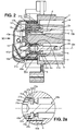
Figure 2 is a cut view of the connector device following the plan II-II of thefigure 1 passing by two electrical contacts, showing a guiding portion of the multicontact rear body. -
Figure 2a is a detail view offigure 2 . -
Figure 3 is a perspective view of a - multicontact subassembly showing three covering plates delimiting a shared portion of three ventilation ducts.
-
Figure 4 is a perspective view of the connector body, viewed from the rear side, showing the front size of a shared portion of three ventilation ducts. -
Figures 4a et 4b are detail views offigure 4 . -
Figure 5 is a side view of the connector device following arrow V of thefigures 1 and6 . -
Figure 6 is a back view of the multicontact rear body. -
Figure 7 is a partial cut view of a lateral cavity provided with a ventilation duct following the plan VII offigures 1 and4 ,6 . -
Figure 8 is a partial cut view of a peripheric cavity following the plan VIII-VIII offigures 1 ,5, 6 . - As illustrated in
figure 1 , the connector device comprises aconnector body 1, sevenelectrical contacts shutter 3. Eachelectrical contact 2a-2g has a connectingportion 4 of a male type. In a variant, the connecting portion could be either of a male type or of a female type. The number of electrical contacts may be any number. Theelectrical contacts 2a-2g can be of different types. For example, thecontact contact 2c could be a ground contact. Thecontacts - The
connector body 1 comprises apanel flange 5 which is afixation element 5 adapted to fix theconnector body 1 to a panel not illustrated in the figure. The panel comprises a through hole through which the connector body is passing. Thepanel flange 5 defines the front side of the connector device (figure 1 ) and the back side (figure 6 ). - The
connector body 1 comprises a plurality ofcontact cavities 6 surrounding the connectingportion 4 of thecorresponding contact 2a-2g. Theconnector body 1 further comprises aperipheral cavity 7 surrounding all the contacts cavities 6. Both thecontact cavities 6 and theperipheral cavity 7 are open to the front side of the connector device in order to receive a complementary part of a complementary connector. Each of thecavities hole duct - The
connector body 1 comprises aperipheral wall 8 surrounding theperipheral cavity 7. Twolateral walls peripheral wall 8 respectively at the left end and at the right end theperipheral wall 8 and surround twolateral cavities 10a, 10b. The left cavity 10a receives a spring mechanism 11 (visible infigure 7 ). Aleft axis 12a is vertically fixed to thelateral wall 9a. Theshutter 3 is rotatably mounted around theleft axis 12a. A right axis (not represented) is vertically fixed to theright wall 9b. Theshutter 3 is provided with aspring clip 13 which cooperates with the right axis to maintain theshutter 3 in a closed position. Theshutter 3 covers theperipheral wall 8 and hermetically seals a frontinner room 14 on which opens all thecavities inner room 14 communicates with a front side atmosphere only temporarily when theshutter 3 is open and when the complementary connector is not yet mated to the connector device. Therefore, the frontinner room 14 is most of the time isolated from the front side atmosphere. The condensation within the front insideroom 14 can be dried via ventilation ducts which extend from thebottom holes - In a variant, a shutter may be rotatably mounted on the
right axis 12b and clipped on theleft axis 12a. - Both
lateral cavities 10a, 10b are also provided with abottom hole respective cavity 10a, 10b. - As illustrated by
figure 2 , the connector device further comprises a multicontactrear body 15 which covers a back side of theconnector body 1. The multicontactrear body 15 comprises abottom wall 16 and a plurality of guidingportions bottom wall 16. Each of the guidingportions cylindrical guiding surface electrical contact contact axis 19b, 19e. - As illustrated in
figures 2 and3 , each of the guidingportions spring arms 21b, 21e surrounding theelectrical contact spring arm 21b, 21e comprises a lockingprojection 22b, 22e which protrudes radially inside the guidingsurface axial stop recess electrical contact axial stop recess - In a variant, the number of spring arms may be any number and may be different for each guiding portion.
- As illustrated in
figure 2a , thepower contact 2e comprises acontact body 24e which is a single-block piece part, machined by bar turning. Thecontact body 24e comprises a backtubular portion 25e into which the cable wire extremity is soldered. The backtubular portion 25e is at the opposite extremity of thecontact body 24e with respect to the connectingportion 4. - The
contact body 24e further comprises a holdingportion 26e extending axially between the backtubular portion 25e and the connectingportion 4. Theannular groove 23e is provided on the holdingportion 26e. The holdingportion 26e extends radially inside the outside diameter of the backtubular portions 25e. So, the diameter of the bar, from which the contact body 24 is machined, corresponds to the outside diameter of the backtubular portion 25e. - The
contact body 24e further comprises a guidingshoulder 48e extending axially at the back of theaxial step recess 23e and extending radially further the backtubular portion 25e. Thespring arm 21e may also comprises aninner guiding shoulder 47e arranged to cooperate with the guidingshoulder 48e. This provides a more precise coaxial guiding of thecontact 2e close to the holdingportion 26e. This allows thecontact 2e to slightly rotate around the holdingportion 26e. The guidingshoulders guiding bending member 49e. - As illustrated in the
figures 3 ,5 ,6 ,8 , the multicontactrear body 15 further comprises aperipheric wall 27 as well as abottom plate 28 and twolateral plates plates peripheral wall 27. - As illustrated in the
figures 3, 4 , theperipheral wall 27 cooperates with aretention element 30 radially protruding from a rearaxial protrusion 31 of theconnector body 1 for attaching themulticontact body 15 to theconnector body 1. - As illustrated in the
figures 2, 2a ,3 , the assembly method comprises a first step of assembling a sub assembly illustrated inFigure 3 . The wire extremity is soldered in the backtubular portion 25e and all the contacts are assembled in a similar way. All the contact assemblies are introduced into the corresponding guidingsurface 18e. During the axial introduction of the contact, the lockingprojections 22e of the guidingportion 17e are deflected radially outwards to a biased position until the contact reaches an axial position in which thelocking projections 22e are aligned with theaxial stop recess 23e. Then, the lockingprojections 22e automatically spring back radially inwards due to the elasticity of thespring arm 21e. - The front side of the locking
projections 22e constitutes a rearwardaxial stop 40e which prevents thecontact 2e from moving rearwards. The backside of the lockingprojection 22e constitutes a forwardaxial stop 41e which prevents thecontact 2e from moving forwards. The rearwardaxial stop 40e and the forwardaxial stop 41e cooperate with theaxial stop recess 23e to hold axially thecontact 2e in both directions of thecontact axis 19e. Additionally, thespring arm 21e comes back in a position compatible with the introduction into the receivingcavity 42e of theconnector body 1. The other contact assemblies are introduced in the multicontactrear holder 15 in a similar way. - In a second step, the sub assembly is introduced in the
connector body 1 and thebead 30 and the elasticperipheral wall 27 attach the sub assembly with theconnector body 1. - In the case where the contact is not fully inserted in its final position, at least one of the locking
projections 22e cannot enter theaxial stop recess 23e and thereby the introduction of the guidingportion 17e into the receivingcavity 42e is made impossible. Thespring arm 21e acts as a mistake-proofing mechanism. The fact that the locking projection does not correctly cooperate with the axial stop recess of the contact during the first step is directly transformed into a stop which makes the second step impossible. - As illustrated in the
figures 4 ,4a , theconnector body 1 comprisesrear protrusions panel flange 5, parallel to the mating axis of the connector device. Each of therear protrusions rear chamber bottom hole lateral plates lateral outlet rear body 15 is attached to the connector body 2, the connector device is provided with twolateral ventilation ducts 35a, 35b extending each from the correspondingbottom hole rear chamber 33a, 33b. Said lateral ventilation ducts 35a,35B are in communication with the rear side atmosphere via thelateral outlet - The
lateral outlet bottom hole figure 4a ). Theventilation duct 35a, 35b comprises baffle means, formed by a portion of the rear protrusion, which allows increasing the residence time of the air flow from the front side atmosphere to the rear side atmosphere and thereby slowdowns the dust flow through the duct. The lateralrear cavity portion ventilation duct 35a, 35b which is delimited, for the rear side by themulticontact body 15, and for the lateral and front side by the connector body 2. - As illustrated in the
figures 4 ,4b , theconnector body 1 further comprises a bottomrear protrusion 36 extending backwards, parallel to the mating axis and forming a baffle means for theventilation duct 37. Theventilation duct 37 extends from the periphericbottom hole 7a to anoutlet 38. The portion of the path of theventilation duct 37 delimited for the rear side by thebottom plate 28 and for the lateral and front side by theconnector body 1 is a shared portion 39 of theventilation duct 37. The shared portion 39 extends along a path having a zigzag shape and extends along a plane which is perpendicular to the mating axis.
Claims (11)
- Multicontact body (15) for electrical connector device, comprising:- an attachment member (27) adapted to cooperate with a connector body (1) of an electrical connector which mates with a complementary electrical connector device for immobilizing the multicontact (15) holder with respect to the connector body (1).- a plurality of individual guiding portions (17e) including each:wherein the multicontact body (15) is a multicontact holder (15) in which each individual guiding portion (17e) includes a second axial stop (41e) adapted to prevent said electrical contact (2e) from moving in a second direction of the guiding axis opposite the first direction, wherein each guiding portion (17e) comprises a spring arm (21e) having a free end provided with a locking projection (22e) which includes said first and second axial stops (40e, 41e) and wherein the locking projection (22e) is radially movable between a biased position in which the locking projection radially extends totally outside the guiding surface (42e) of the corresponding guiding portion (17e), and a stopping position in which the locking projection (22e) radially extends at least partially inside said guiding surface (42e), so as to be adapted to radially enter in an axial stop recess (23e) of an electrical contact (2e), characterized in that the spring arm (21e) comprises an inner guiding shoulder (47e) arranged to cooperate with a guiding shoulder (48e) provided on a contact body (24e) of said contact (2e).* a guiding surface (18e) adapted to guide one electrical contact of the electrical connector device along a guiding axis, and* a first axial stop (40e) adapted to prevent said electrical contact (2e) from moving into said electrical connector device towards a first direction of the guiding axis,
- Multicontact body (15) according to claim 1, comprising:- an assembling surface (45e) by which the multicontact body (15) can be assembled together with the connector body (1) and- a mistake-proofing mechanism (21e) adapted to prevent the assembling surface (45e) from cooperating with the connector body (1), at least one of the first and second axial stops (40e, 41e) being movable and adapted to action the mistake-proofing mechanism (21e).
- Multicontact body according to the claims 1 and 2 together, wherein the assembling surface (45e) includes the radially outside surface of each guiding portion (17e) when the locking projection (22e) of the spring arms (21e) are in the stopping position and wherein the mistake-proofing mechanism is provided with the spring arm (21e) in the biased position.
- Multicontact body (15) according to any of the claims 1 to 3, comprising a bottom wall (16) from which the individual guiding portions (17e) extend, and further comprises at least one cable guide (46) axially protruding backwards from the bottom wall (16).
- Electrical connector device, comprising:- a connector body (1) including a forward direction of a mating axis toward which the connector body (1) is adapted to mate with a complementary electrical connector device,- a plurality of electrical contacts (2e),- a multicontact rear body (15) according to one of the preceding claims, attached to the connector body (1) and comprising for each electrical contact (2e), an individual guiding portion (17e) adapted to guide said electrical contact (2e) substantially parallel to the mating axis, said individual guiding portion (17e) comprising a rearward axial stop (40e) adapted to prevent said contact (2e) from moving rearwards.
- Connector device according to claim 5, wherein the connector body (1) comprises a plurality of receiving cavities (42a) being each large enough to receive one of the individual guiding portions (17e) when the locking projection (22e) of the spring arm (21e) of the corresponding individual guiding portion is in the stopping position, wherein each of the receiving cavities (42e) is adapted to prevent the corresponding guiding portion (17e) from entering into said cavity (42e) when the corresponding locking projection (22e) is in a wrongly latch radial position in which said locking projection (22e) touches the corresponding electrical contact (2e) by a zone other than the axial stop recess (23e).
- Connector device according to claim 6, comprising an attachment mechanism (27-30) adapted to attach the multicontact holder (15) and the connector body (1) together in a relative axial latch position when all the guiding portions (17e) enter into the corresponding cavity (42e) and is adapted to leave the multicontact holder (15) axially free from the connector body (1) when at least one guiding portion (17e) is not entered into the corresponding cavity (42e).
- Connector device according to any of the claims 5 to 7, wherein the locking projection (22e) is movable between the stopping position and a biased position in which the locking projection radially extends totally further an outside diameter of the corresponding electrical contact (2e).
- Connector device according to any of the claims 5-8, wherein at least one of the electrical contacts (2e) comprises a one-piece contact body (24e) extending along a contact axis, the contact body (24e) including:- a front connecting portion (4) adapted to electrically connect a complementary electrical contact,- a back tubular portion (25e) being adapted to receive and attach a electrical wire extremity, and- a contact holding portion (26e) extending axially between the front connecting portion (4) and the back tubular portion (25e) and being adapted to cooperate with an housing (1-15) of the connector device for being axially hold,the contact holding portion (26e) comprising an axial stop recess (23e) adapted to receive a rearward axial stop (40e) and a forward axial stop (41e) of the connector housing (1-15).
- Connector device according to claim 9, wherein the axial stop recess (23e) is an annular groove.
- Connector device according to claim 9 or 10, wherein the contact holding portion (26e) of contact body (1) radially extends inside an outside diameter of the back tubular portion (25e).
Applications Claiming Priority (2)
| Application Number | Priority Date | Filing Date | Title |
|---|---|---|---|
| IB2011001235 | 2011-04-28 | ||
| PCT/EP2012/057867 WO2012146766A1 (en) | 2011-04-28 | 2012-04-27 | Multicontact body, electrical contact, electrical connector device and assembly method |
Publications (2)
| Publication Number | Publication Date |
|---|---|
| EP2702642A1 EP2702642A1 (en) | 2014-03-05 |
| EP2702642B1 true EP2702642B1 (en) | 2016-11-30 |
Family
ID=46062263
Family Applications (1)
| Application Number | Title | Priority Date | Filing Date |
|---|---|---|---|
| EP12720468.3A Active EP2702642B1 (en) | 2011-04-28 | 2012-04-27 | Multicontact body and electrical connector device |
Country Status (2)
| Country | Link |
|---|---|
| EP (1) | EP2702642B1 (en) |
| WO (1) | WO2012146766A1 (en) |
Families Citing this family (14)
| Publication number | Priority date | Publication date | Assignee | Title |
|---|---|---|---|---|
| CN105144502B (en) * | 2013-03-19 | 2017-07-28 | 住友电装株式会社 | Vehicle-side connector |
| SE537179C2 (en) * | 2013-06-07 | 2015-02-24 | Bt Products Ab | Warehouse truck with truck contact, as well as adapted truck load contact and truck operating bracket |
| DE102013213336B4 (en) * | 2013-07-08 | 2024-02-01 | Te Connectivity Germany Gmbh | ELECTRICAL CONNECTOR, CHARGING SOCKET AND CONNECTOR SYSTEM FOR AN ELECTRIC OR HYBRID VEHICLE |
| JP2015103376A (en) * | 2013-11-25 | 2015-06-04 | 住友電装株式会社 | Vehicle-side connector |
| JP2015103378A (en) * | 2013-11-25 | 2015-06-04 | 住友電装株式会社 | Vehicle side connector |
| DE102014111185A1 (en) | 2014-08-06 | 2016-02-11 | Phoenix Contact E-Mobility Gmbh | Connector part with a temperature sensor device |
| DE112016004047B4 (en) | 2015-09-07 | 2023-09-21 | Yazaki Corporation | Interconnects |
| JP6607133B2 (en) * | 2016-04-11 | 2019-11-20 | 住友電装株式会社 | connector |
| DE102016122396B3 (en) * | 2016-11-21 | 2018-03-22 | Amphenol-Tuchel Electronics Gmbh | Electrical plug connection with an electrical plug |
| DE202018003420U1 (en) | 2018-07-23 | 2018-08-16 | Heraeus Sensor Technology Gmbh | Connector with flip-chip measuring element |
| US12319161B2 (en) | 2021-05-27 | 2025-06-03 | Ford Global Technologies, Llc | Adaptor plug for an electric vehicle |
| US11752891B2 (en) * | 2021-05-27 | 2023-09-12 | Ford Global Technologies, Llc | Charging system for a vehicle |
| JP7567711B2 (en) * | 2021-07-29 | 2024-10-16 | 住友電装株式会社 | Charging connector |
| JP2023182337A (en) * | 2022-06-14 | 2023-12-26 | 日本航空電子工業株式会社 | connector |
Citations (1)
| Publication number | Priority date | Publication date | Assignee | Title |
|---|---|---|---|---|
| DE3125089A1 (en) * | 1981-06-26 | 1983-01-13 | Daimler-Benz Ag, 7000 Stuttgart | Plug element of a plug connection for electrical cables |
Family Cites Families (3)
| Publication number | Priority date | Publication date | Assignee | Title |
|---|---|---|---|---|
| US4544220A (en) * | 1983-12-28 | 1985-10-01 | Amp Incorporated | Connector having means for positively seating contacts |
| US5643009A (en) * | 1996-02-26 | 1997-07-01 | The Whitaker Corporation | Electrical connector having a pivot lock |
| US6210036B1 (en) * | 1996-09-06 | 2001-04-03 | Gerald P. Eberle | Connector thermal sensor |
-
2012
- 2012-04-27 WO PCT/EP2012/057867 patent/WO2012146766A1/en not_active Ceased
- 2012-04-27 EP EP12720468.3A patent/EP2702642B1/en active Active
Patent Citations (1)
| Publication number | Priority date | Publication date | Assignee | Title |
|---|---|---|---|---|
| DE3125089A1 (en) * | 1981-06-26 | 1983-01-13 | Daimler-Benz Ag, 7000 Stuttgart | Plug element of a plug connection for electrical cables |
Also Published As
| Publication number | Publication date |
|---|---|
| EP2702642A1 (en) | 2014-03-05 |
| WO2012146766A1 (en) | 2012-11-01 |
Similar Documents
| Publication | Publication Date | Title |
|---|---|---|
| WO2012146766A1 (en) | Multicontact body, electrical contact, electrical connector device and assembly method | |
| EP3544124B1 (en) | Connector | |
| CN110383591B (en) | Shielding terminal and shielding connector | |
| US8333613B2 (en) | Header assembly | |
| JP6994880B2 (en) | Electrical cable connector with rotatable housing | |
| EP2532056B1 (en) | Header connector assembly | |
| US8172579B2 (en) | Electrical connector having dust-proof shutter driven by magnetic force | |
| US7744231B2 (en) | Electrical connector with illumination waveguide | |
| CN107394490B (en) | Cable assembly with improved cable retention | |
| US7794262B2 (en) | Connector assembly with electromagnetic interference contacts | |
| CN105144502B (en) | Vehicle-side connector | |
| WO2018163787A1 (en) | Shielded terminal and shielded connector | |
| WO2008127518A1 (en) | High voltage shielded electrical connector assembly | |
| EP3389149B1 (en) | Electrical connector | |
| WO2013046668A1 (en) | Shield connector and method of assembling shield connector | |
| US7077703B2 (en) | Plug connector | |
| JP2018181404A (en) | Electrical connector | |
| KR102101713B1 (en) | Brush fixing device for motor | |
| CN111201678A (en) | Connector | |
| JP2017004949A (en) | Locking device for electric connector | |
| EP2702641B1 (en) | Electrical connector housing and device for vehicle charging system | |
| KR20220057581A (en) | electrical plug connector | |
| WO2012175573A1 (en) | Electrical multicontact plug and assembly method for charging system | |
| US20240030656A1 (en) | Shield Contact Element and Method of Manufacturing Such a Shield Contact Element | |
| CN211208752U (en) | Connector shell assembly and connector |
Legal Events
| Date | Code | Title | Description |
|---|---|---|---|
| PUAI | Public reference made under article 153(3) epc to a published international application that has entered the european phase |
Free format text: ORIGINAL CODE: 0009012 |
|
| 17P | Request for examination filed |
Effective date: 20131128 |
|
| AK | Designated contracting states |
Kind code of ref document: A1 Designated state(s): AL AT BE BG CH CY CZ DE DK EE ES FI FR GB GR HR HU IE IS IT LI LT LU LV MC MK MT NL NO PL PT RO RS SE SI SK SM TR |
|
| DAX | Request for extension of the european patent (deleted) | ||
| 17Q | First examination report despatched |
Effective date: 20160211 |
|
| GRAP | Despatch of communication of intention to grant a patent |
Free format text: ORIGINAL CODE: EPIDOSNIGR1 |
|
| RIC1 | Information provided on ipc code assigned before grant |
Ipc: H01R 13/52 20060101ALN20160608BHEP Ipc: H01R 13/436 20060101ALI20160608BHEP Ipc: H01R 13/66 20060101ALN20160608BHEP Ipc: H01R 13/424 20060101ALI20160608BHEP Ipc: B60L 11/18 20060101ALI20160608BHEP Ipc: H01R 13/506 20060101AFI20160608BHEP Ipc: H01R 107/00 20060101ALI20160608BHEP |
|
| INTG | Intention to grant announced |
Effective date: 20160630 |
|
| RIN1 | Information on inventor provided before grant (corrected) |
Inventor name: MULOT, GERARD Inventor name: AESCHBACHER, MICHEL Inventor name: DUQUESNE, ARNAUD |
|
| GRAJ | Information related to disapproval of communication of intention to grant by the applicant or resumption of examination proceedings by the epo deleted |
Free format text: ORIGINAL CODE: EPIDOSDIGR1 |
|
| GRAR | Information related to intention to grant a patent recorded |
Free format text: ORIGINAL CODE: EPIDOSNIGR71 |
|
| GRAS | Grant fee paid |
Free format text: ORIGINAL CODE: EPIDOSNIGR3 |
|
| GRAA | (expected) grant |
Free format text: ORIGINAL CODE: 0009210 |
|
| INTC | Intention to grant announced (deleted) | ||
| RIC1 | Information provided on ipc code assigned before grant |
Ipc: B60L 11/18 20060101ALI20161012BHEP Ipc: H01R 13/506 20060101AFI20161012BHEP Ipc: H01R 13/424 20060101ALI20161012BHEP Ipc: H01R 13/66 20060101ALN20161012BHEP Ipc: H01R 13/436 20060101ALI20161012BHEP Ipc: H01R 107/00 20060101ALI20161012BHEP Ipc: H01R 13/52 20060101ALN20161012BHEP |
|
| INTG | Intention to grant announced |
Effective date: 20161020 |
|
| AK | Designated contracting states |
Kind code of ref document: B1 Designated state(s): AL AT BE BG CH CY CZ DE DK EE ES FI FR GB GR HR HU IE IS IT LI LT LU LV MC MK MT NL NO PL PT RO RS SE SI SK SM TR |
|
| REG | Reference to a national code |
Ref country code: CH Ref legal event code: EP Ref country code: GB Ref legal event code: FG4D |
|
| REG | Reference to a national code |
Ref country code: AT Ref legal event code: REF Ref document number: 850606 Country of ref document: AT Kind code of ref document: T Effective date: 20161215 |
|
| REG | Reference to a national code |
Ref country code: IE Ref legal event code: FG4D |
|
| REG | Reference to a national code |
Ref country code: DE Ref legal event code: R096 Ref document number: 602012026009 Country of ref document: DE |
|
| PG25 | Lapsed in a contracting state [announced via postgrant information from national office to epo] |
Ref country code: LV Free format text: LAPSE BECAUSE OF FAILURE TO SUBMIT A TRANSLATION OF THE DESCRIPTION OR TO PAY THE FEE WITHIN THE PRESCRIBED TIME-LIMIT Effective date: 20161130 |
|
| REG | Reference to a national code |
Ref country code: LT Ref legal event code: MG4D |
|
| REG | Reference to a national code |
Ref country code: NL Ref legal event code: MP Effective date: 20161130 |
|
| REG | Reference to a national code |
Ref country code: AT Ref legal event code: MK05 Ref document number: 850606 Country of ref document: AT Kind code of ref document: T Effective date: 20161130 |
|
| REG | Reference to a national code |
Ref country code: FR Ref legal event code: PLFP Year of fee payment: 6 |
|
| PG25 | Lapsed in a contracting state [announced via postgrant information from national office to epo] |
Ref country code: LT Free format text: LAPSE BECAUSE OF FAILURE TO SUBMIT A TRANSLATION OF THE DESCRIPTION OR TO PAY THE FEE WITHIN THE PRESCRIBED TIME-LIMIT Effective date: 20161130 Ref country code: NO Free format text: LAPSE BECAUSE OF FAILURE TO SUBMIT A TRANSLATION OF THE DESCRIPTION OR TO PAY THE FEE WITHIN THE PRESCRIBED TIME-LIMIT Effective date: 20170228 Ref country code: SE Free format text: LAPSE BECAUSE OF FAILURE TO SUBMIT A TRANSLATION OF THE DESCRIPTION OR TO PAY THE FEE WITHIN THE PRESCRIBED TIME-LIMIT Effective date: 20161130 |
|
| PG25 | Lapsed in a contracting state [announced via postgrant information from national office to epo] |
Ref country code: ES Free format text: LAPSE BECAUSE OF FAILURE TO SUBMIT A TRANSLATION OF THE DESCRIPTION OR TO PAY THE FEE WITHIN THE PRESCRIBED TIME-LIMIT Effective date: 20161130 Ref country code: RS Free format text: LAPSE BECAUSE OF FAILURE TO SUBMIT A TRANSLATION OF THE DESCRIPTION OR TO PAY THE FEE WITHIN THE PRESCRIBED TIME-LIMIT Effective date: 20161130 Ref country code: PL Free format text: LAPSE BECAUSE OF FAILURE TO SUBMIT A TRANSLATION OF THE DESCRIPTION OR TO PAY THE FEE WITHIN THE PRESCRIBED TIME-LIMIT Effective date: 20161130 Ref country code: PT Free format text: LAPSE BECAUSE OF FAILURE TO SUBMIT A TRANSLATION OF THE DESCRIPTION OR TO PAY THE FEE WITHIN THE PRESCRIBED TIME-LIMIT Effective date: 20170330 Ref country code: HR Free format text: LAPSE BECAUSE OF FAILURE TO SUBMIT A TRANSLATION OF THE DESCRIPTION OR TO PAY THE FEE WITHIN THE PRESCRIBED TIME-LIMIT Effective date: 20161130 Ref country code: FI Free format text: LAPSE BECAUSE OF FAILURE TO SUBMIT A TRANSLATION OF THE DESCRIPTION OR TO PAY THE FEE WITHIN THE PRESCRIBED TIME-LIMIT Effective date: 20161130 Ref country code: AT Free format text: LAPSE BECAUSE OF FAILURE TO SUBMIT A TRANSLATION OF THE DESCRIPTION OR TO PAY THE FEE WITHIN THE PRESCRIBED TIME-LIMIT Effective date: 20161130 |
|
| PG25 | Lapsed in a contracting state [announced via postgrant information from national office to epo] |
Ref country code: NL Free format text: LAPSE BECAUSE OF FAILURE TO SUBMIT A TRANSLATION OF THE DESCRIPTION OR TO PAY THE FEE WITHIN THE PRESCRIBED TIME-LIMIT Effective date: 20161130 |
|
| PG25 | Lapsed in a contracting state [announced via postgrant information from national office to epo] |
Ref country code: EE Free format text: LAPSE BECAUSE OF FAILURE TO SUBMIT A TRANSLATION OF THE DESCRIPTION OR TO PAY THE FEE WITHIN THE PRESCRIBED TIME-LIMIT Effective date: 20161130 Ref country code: CZ Free format text: LAPSE BECAUSE OF FAILURE TO SUBMIT A TRANSLATION OF THE DESCRIPTION OR TO PAY THE FEE WITHIN THE PRESCRIBED TIME-LIMIT Effective date: 20161130 Ref country code: DK Free format text: LAPSE BECAUSE OF FAILURE TO SUBMIT A TRANSLATION OF THE DESCRIPTION OR TO PAY THE FEE WITHIN THE PRESCRIBED TIME-LIMIT Effective date: 20161130 Ref country code: RO Free format text: LAPSE BECAUSE OF FAILURE TO SUBMIT A TRANSLATION OF THE DESCRIPTION OR TO PAY THE FEE WITHIN THE PRESCRIBED TIME-LIMIT Effective date: 20161130 Ref country code: SK Free format text: LAPSE BECAUSE OF FAILURE TO SUBMIT A TRANSLATION OF THE DESCRIPTION OR TO PAY THE FEE WITHIN THE PRESCRIBED TIME-LIMIT Effective date: 20161130 |
|
| PG25 | Lapsed in a contracting state [announced via postgrant information from national office to epo] |
Ref country code: IT Free format text: LAPSE BECAUSE OF FAILURE TO SUBMIT A TRANSLATION OF THE DESCRIPTION OR TO PAY THE FEE WITHIN THE PRESCRIBED TIME-LIMIT Effective date: 20161130 Ref country code: BG Free format text: LAPSE BECAUSE OF FAILURE TO SUBMIT A TRANSLATION OF THE DESCRIPTION OR TO PAY THE FEE WITHIN THE PRESCRIBED TIME-LIMIT Effective date: 20170228 Ref country code: SM Free format text: LAPSE BECAUSE OF FAILURE TO SUBMIT A TRANSLATION OF THE DESCRIPTION OR TO PAY THE FEE WITHIN THE PRESCRIBED TIME-LIMIT Effective date: 20161130 Ref country code: BE Free format text: LAPSE BECAUSE OF FAILURE TO SUBMIT A TRANSLATION OF THE DESCRIPTION OR TO PAY THE FEE WITHIN THE PRESCRIBED TIME-LIMIT Effective date: 20161130 |
|
| REG | Reference to a national code |
Ref country code: DE Ref legal event code: R097 Ref document number: 602012026009 Country of ref document: DE |
|
| PLBE | No opposition filed within time limit |
Free format text: ORIGINAL CODE: 0009261 |
|
| STAA | Information on the status of an ep patent application or granted ep patent |
Free format text: STATUS: NO OPPOSITION FILED WITHIN TIME LIMIT |
|
| 26N | No opposition filed |
Effective date: 20170831 |
|
| PG25 | Lapsed in a contracting state [announced via postgrant information from national office to epo] |
Ref country code: SI Free format text: LAPSE BECAUSE OF FAILURE TO SUBMIT A TRANSLATION OF THE DESCRIPTION OR TO PAY THE FEE WITHIN THE PRESCRIBED TIME-LIMIT Effective date: 20161130 |
|
| REG | Reference to a national code |
Ref country code: CH Ref legal event code: PL |
|
| REG | Reference to a national code |
Ref country code: IE Ref legal event code: MM4A |
|
| PG25 | Lapsed in a contracting state [announced via postgrant information from national office to epo] |
Ref country code: MC Free format text: LAPSE BECAUSE OF FAILURE TO SUBMIT A TRANSLATION OF THE DESCRIPTION OR TO PAY THE FEE WITHIN THE PRESCRIBED TIME-LIMIT Effective date: 20161130 |
|
| PG25 | Lapsed in a contracting state [announced via postgrant information from national office to epo] |
Ref country code: LI Free format text: LAPSE BECAUSE OF NON-PAYMENT OF DUE FEES Effective date: 20170430 Ref country code: CH Free format text: LAPSE BECAUSE OF NON-PAYMENT OF DUE FEES Effective date: 20170430 Ref country code: LU Free format text: LAPSE BECAUSE OF NON-PAYMENT OF DUE FEES Effective date: 20170427 |
|
| REG | Reference to a national code |
Ref country code: FR Ref legal event code: PLFP Year of fee payment: 7 |
|
| PG25 | Lapsed in a contracting state [announced via postgrant information from national office to epo] |
Ref country code: IE Free format text: LAPSE BECAUSE OF NON-PAYMENT OF DUE FEES Effective date: 20170427 |
|
| PG25 | Lapsed in a contracting state [announced via postgrant information from national office to epo] |
Ref country code: MT Free format text: LAPSE BECAUSE OF NON-PAYMENT OF DUE FEES Effective date: 20170427 |
|
| REG | Reference to a national code |
Ref country code: DE Ref legal event code: R081 Ref document number: 602012026009 Country of ref document: DE Owner name: APTIV TECHNOLOGIES LIMITED, BB Free format text: FORMER OWNER: DELPHI INTERNATIONAL OPERATIONS LUXEMBOURG S.A R.L., BASCHARAGE, LU |
|
| REG | Reference to a national code |
Ref country code: GB Ref legal event code: 732E Free format text: REGISTERED BETWEEN 20181213 AND 20181219 |
|
| PG25 | Lapsed in a contracting state [announced via postgrant information from national office to epo] |
Ref country code: HU Free format text: LAPSE BECAUSE OF FAILURE TO SUBMIT A TRANSLATION OF THE DESCRIPTION OR TO PAY THE FEE WITHIN THE PRESCRIBED TIME-LIMIT; INVALID AB INITIO Effective date: 20120427 |
|
| PG25 | Lapsed in a contracting state [announced via postgrant information from national office to epo] |
Ref country code: CY Free format text: LAPSE BECAUSE OF NON-PAYMENT OF DUE FEES Effective date: 20161130 |
|
| PG25 | Lapsed in a contracting state [announced via postgrant information from national office to epo] |
Ref country code: MK Free format text: LAPSE BECAUSE OF FAILURE TO SUBMIT A TRANSLATION OF THE DESCRIPTION OR TO PAY THE FEE WITHIN THE PRESCRIBED TIME-LIMIT Effective date: 20161130 |
|
| PG25 | Lapsed in a contracting state [announced via postgrant information from national office to epo] |
Ref country code: TR Free format text: LAPSE BECAUSE OF FAILURE TO SUBMIT A TRANSLATION OF THE DESCRIPTION OR TO PAY THE FEE WITHIN THE PRESCRIBED TIME-LIMIT Effective date: 20161130 |
|
| PG25 | Lapsed in a contracting state [announced via postgrant information from national office to epo] |
Ref country code: GR Free format text: LAPSE BECAUSE OF FAILURE TO SUBMIT A TRANSLATION OF THE DESCRIPTION OR TO PAY THE FEE WITHIN THE PRESCRIBED TIME-LIMIT Effective date: 20161130 |
|
| PG25 | Lapsed in a contracting state [announced via postgrant information from national office to epo] |
Ref country code: AL Free format text: LAPSE BECAUSE OF FAILURE TO SUBMIT A TRANSLATION OF THE DESCRIPTION OR TO PAY THE FEE WITHIN THE PRESCRIBED TIME-LIMIT Effective date: 20161130 Ref country code: IS Free format text: LAPSE BECAUSE OF FAILURE TO SUBMIT A TRANSLATION OF THE DESCRIPTION OR TO PAY THE FEE WITHIN THE PRESCRIBED TIME-LIMIT Effective date: 20170330 |
|
| P01 | Opt-out of the competence of the unified patent court (upc) registered |
Effective date: 20230425 |
|
| REG | Reference to a national code |
Ref country code: DE Ref legal event code: R081 Ref document number: 602012026009 Country of ref document: DE Owner name: APTIV TECHNOLOGIES AG, CH Free format text: FORMER OWNER: APTIV TECHNOLOGIES LIMITED, ST. MICHAEL, BB |
|
| PGFP | Annual fee paid to national office [announced via postgrant information from national office to epo] |
Ref country code: DE Payment date: 20250313 Year of fee payment: 14 |
|
| PGFP | Annual fee paid to national office [announced via postgrant information from national office to epo] |
Ref country code: FR Payment date: 20250404 Year of fee payment: 14 |
|
| PGFP | Annual fee paid to national office [announced via postgrant information from national office to epo] |
Ref country code: GB Payment date: 20260305 Year of fee payment: 15 |