EP2701596B1 - Electrolyte and ph monitoring for fluid removal processes - Google Patents
Electrolyte and ph monitoring for fluid removal processes Download PDFInfo
- Publication number
- EP2701596B1 EP2701596B1 EP12722951.6A EP12722951A EP2701596B1 EP 2701596 B1 EP2701596 B1 EP 2701596B1 EP 12722951 A EP12722951 A EP 12722951A EP 2701596 B1 EP2701596 B1 EP 2701596B1
- Authority
- EP
- European Patent Office
- Prior art keywords
- blood
- fluid
- sensor
- dialysate
- medium
- Prior art date
- Legal status (The legal status is an assumption and is not a legal conclusion. Google has not performed a legal analysis and makes no representation as to the accuracy of the status listed.)
- Active
Links
Images

Classifications
-
- A—HUMAN NECESSITIES
- A61—MEDICAL OR VETERINARY SCIENCE; HYGIENE
- A61M—DEVICES FOR INTRODUCING MEDIA INTO, OR ONTO, THE BODY; DEVICES FOR TRANSDUCING BODY MEDIA OR FOR TAKING MEDIA FROM THE BODY; DEVICES FOR PRODUCING OR ENDING SLEEP OR STUPOR
- A61M1/00—Suction or pumping devices for medical purposes; Devices for carrying-off, for treatment of, or for carrying-over, body-liquids; Drainage systems
- A61M1/14—Dialysis systems; Artificial kidneys; Blood oxygenators ; Reciprocating systems for treatment of body fluids, e.g. single needle systems for hemofiltration or pheresis
- A61M1/16—Dialysis systems; Artificial kidneys; Blood oxygenators ; Reciprocating systems for treatment of body fluids, e.g. single needle systems for hemofiltration or pheresis with membranes
- A61M1/1601—Control or regulation
- A61M1/1603—Regulation parameters
-
- A—HUMAN NECESSITIES
- A61—MEDICAL OR VETERINARY SCIENCE; HYGIENE
- A61B—DIAGNOSIS; SURGERY; IDENTIFICATION
- A61B5/00—Measuring for diagnostic purposes; Identification of persons
- A61B5/0002—Remote monitoring of patients using telemetry, e.g. transmission of vital signals via a communication network
- A61B5/0031—Implanted circuitry
-
- A—HUMAN NECESSITIES
- A61—MEDICAL OR VETERINARY SCIENCE; HYGIENE
- A61B—DIAGNOSIS; SURGERY; IDENTIFICATION
- A61B5/00—Measuring for diagnostic purposes; Identification of persons
- A61B5/02—Detecting, measuring or recording pulse, heart rate, blood pressure or blood flow; Combined pulse/heart-rate/blood pressure determination; Evaluating a cardiovascular condition not otherwise provided for, e.g. using combinations of techniques provided for in this group with electrocardiography or electroauscultation; Heart catheters for measuring blood pressure
- A61B5/026—Measuring blood flow
- A61B5/0295—Measuring blood flow using plethysmography, i.e. measuring the variations in the volume of a body part as modified by the circulation of blood therethrough, e.g. impedance plethysmography
-
- A—HUMAN NECESSITIES
- A61—MEDICAL OR VETERINARY SCIENCE; HYGIENE
- A61B—DIAGNOSIS; SURGERY; IDENTIFICATION
- A61B5/00—Measuring for diagnostic purposes; Identification of persons
- A61B5/05—Detecting, measuring or recording for diagnosis by means of electric currents or magnetic fields; Measuring using microwaves or radio waves
- A61B5/053—Measuring electrical impedance or conductance of a portion of the body
- A61B5/0537—Measuring body composition by impedance, e.g. tissue hydration or fat content
-
- A—HUMAN NECESSITIES
- A61—MEDICAL OR VETERINARY SCIENCE; HYGIENE
- A61B—DIAGNOSIS; SURGERY; IDENTIFICATION
- A61B5/00—Measuring for diagnostic purposes; Identification of persons
- A61B5/145—Measuring characteristics of blood in vivo, e.g. gas concentration, pH value; Measuring characteristics of body fluids or tissues, e.g. interstitial fluid, cerebral tissue
- A61B5/14503—Measuring characteristics of blood in vivo, e.g. gas concentration, pH value; Measuring characteristics of body fluids or tissues, e.g. interstitial fluid, cerebral tissue invasive, e.g. introduced into the body by a catheter or needle or using implanted sensors
-
- A—HUMAN NECESSITIES
- A61—MEDICAL OR VETERINARY SCIENCE; HYGIENE
- A61B—DIAGNOSIS; SURGERY; IDENTIFICATION
- A61B5/00—Measuring for diagnostic purposes; Identification of persons
- A61B5/145—Measuring characteristics of blood in vivo, e.g. gas concentration, pH value; Measuring characteristics of body fluids or tissues, e.g. interstitial fluid, cerebral tissue
- A61B5/14535—Measuring characteristics of blood in vivo, e.g. gas concentration, pH value; Measuring characteristics of body fluids or tissues, e.g. interstitial fluid, cerebral tissue for measuring haematocrit
-
- A—HUMAN NECESSITIES
- A61—MEDICAL OR VETERINARY SCIENCE; HYGIENE
- A61B—DIAGNOSIS; SURGERY; IDENTIFICATION
- A61B5/00—Measuring for diagnostic purposes; Identification of persons
- A61B5/145—Measuring characteristics of blood in vivo, e.g. gas concentration, pH value; Measuring characteristics of body fluids or tissues, e.g. interstitial fluid, cerebral tissue
- A61B5/14539—Measuring characteristics of blood in vivo, e.g. gas concentration, pH value; Measuring characteristics of body fluids or tissues, e.g. interstitial fluid, cerebral tissue for measuring pH
-
- A—HUMAN NECESSITIES
- A61—MEDICAL OR VETERINARY SCIENCE; HYGIENE
- A61B—DIAGNOSIS; SURGERY; IDENTIFICATION
- A61B5/00—Measuring for diagnostic purposes; Identification of persons
- A61B5/145—Measuring characteristics of blood in vivo, e.g. gas concentration, pH value; Measuring characteristics of body fluids or tissues, e.g. interstitial fluid, cerebral tissue
- A61B5/14546—Measuring characteristics of blood in vivo, e.g. gas concentration, pH value; Measuring characteristics of body fluids or tissues, e.g. interstitial fluid, cerebral tissue for measuring analytes not otherwise provided for, e.g. ions, cytochromes
-
- A—HUMAN NECESSITIES
- A61—MEDICAL OR VETERINARY SCIENCE; HYGIENE
- A61B—DIAGNOSIS; SURGERY; IDENTIFICATION
- A61B5/00—Measuring for diagnostic purposes; Identification of persons
- A61B5/48—Other medical applications
- A61B5/4836—Diagnosis combined with treatment in closed-loop systems or methods
-
- A—HUMAN NECESSITIES
- A61—MEDICAL OR VETERINARY SCIENCE; HYGIENE
- A61B—DIAGNOSIS; SURGERY; IDENTIFICATION
- A61B5/00—Measuring for diagnostic purposes; Identification of persons
- A61B5/48—Other medical applications
- A61B5/4848—Monitoring or testing the effects of treatment, e.g. of medication
-
- A—HUMAN NECESSITIES
- A61—MEDICAL OR VETERINARY SCIENCE; HYGIENE
- A61B—DIAGNOSIS; SURGERY; IDENTIFICATION
- A61B5/00—Measuring for diagnostic purposes; Identification of persons
- A61B5/68—Arrangements of detecting, measuring or recording means, e.g. sensors, in relation to patient
- A61B5/6846—Arrangements of detecting, measuring or recording means, e.g. sensors, in relation to patient specially adapted to be brought in contact with an internal body part, i.e. invasive
- A61B5/6847—Arrangements of detecting, measuring or recording means, e.g. sensors, in relation to patient specially adapted to be brought in contact with an internal body part, i.e. invasive mounted on an invasive device
- A61B5/6866—Extracorporeal blood circuits, e.g. dialysis circuits
-
- A—HUMAN NECESSITIES
- A61—MEDICAL OR VETERINARY SCIENCE; HYGIENE
- A61M—DEVICES FOR INTRODUCING MEDIA INTO, OR ONTO, THE BODY; DEVICES FOR TRANSDUCING BODY MEDIA OR FOR TAKING MEDIA FROM THE BODY; DEVICES FOR PRODUCING OR ENDING SLEEP OR STUPOR
- A61M1/00—Suction or pumping devices for medical purposes; Devices for carrying-off, for treatment of, or for carrying-over, body-liquids; Drainage systems
- A61M1/14—Dialysis systems; Artificial kidneys; Blood oxygenators ; Reciprocating systems for treatment of body fluids, e.g. single needle systems for hemofiltration or pheresis
- A61M1/16—Dialysis systems; Artificial kidneys; Blood oxygenators ; Reciprocating systems for treatment of body fluids, e.g. single needle systems for hemofiltration or pheresis with membranes
- A61M1/1601—Control or regulation
- A61M1/1603—Regulation parameters
- A61M1/1605—Physical characteristics of the dialysate fluid
- A61M1/1607—Physical characteristics of the dialysate fluid before use, i.e. upstream of dialyser
-
- A—HUMAN NECESSITIES
- A61—MEDICAL OR VETERINARY SCIENCE; HYGIENE
- A61M—DEVICES FOR INTRODUCING MEDIA INTO, OR ONTO, THE BODY; DEVICES FOR TRANSDUCING BODY MEDIA OR FOR TAKING MEDIA FROM THE BODY; DEVICES FOR PRODUCING OR ENDING SLEEP OR STUPOR
- A61M1/00—Suction or pumping devices for medical purposes; Devices for carrying-off, for treatment of, or for carrying-over, body-liquids; Drainage systems
- A61M1/14—Dialysis systems; Artificial kidneys; Blood oxygenators ; Reciprocating systems for treatment of body fluids, e.g. single needle systems for hemofiltration or pheresis
- A61M1/16—Dialysis systems; Artificial kidneys; Blood oxygenators ; Reciprocating systems for treatment of body fluids, e.g. single needle systems for hemofiltration or pheresis with membranes
- A61M1/1601—Control or regulation
- A61M1/1613—Profiling or modelling of patient or predicted treatment evolution or outcome
-
- A—HUMAN NECESSITIES
- A61—MEDICAL OR VETERINARY SCIENCE; HYGIENE
- A61M—DEVICES FOR INTRODUCING MEDIA INTO, OR ONTO, THE BODY; DEVICES FOR TRANSDUCING BODY MEDIA OR FOR TAKING MEDIA FROM THE BODY; DEVICES FOR PRODUCING OR ENDING SLEEP OR STUPOR
- A61M1/00—Suction or pumping devices for medical purposes; Devices for carrying-off, for treatment of, or for carrying-over, body-liquids; Drainage systems
- A61M1/14—Dialysis systems; Artificial kidneys; Blood oxygenators ; Reciprocating systems for treatment of body fluids, e.g. single needle systems for hemofiltration or pheresis
- A61M1/28—Peritoneal dialysis ; Other peritoneal treatment, e.g. oxygenation
-
- A—HUMAN NECESSITIES
- A61—MEDICAL OR VETERINARY SCIENCE; HYGIENE
- A61M—DEVICES FOR INTRODUCING MEDIA INTO, OR ONTO, THE BODY; DEVICES FOR TRANSDUCING BODY MEDIA OR FOR TAKING MEDIA FROM THE BODY; DEVICES FOR PRODUCING OR ENDING SLEEP OR STUPOR
- A61M1/00—Suction or pumping devices for medical purposes; Devices for carrying-off, for treatment of, or for carrying-over, body-liquids; Drainage systems
- A61M1/34—Filtering material out of the blood by passing it through a membrane, i.e. hemofiltration or diafiltration
- A61M1/3403—Regulation parameters
-
- A—HUMAN NECESSITIES
- A61—MEDICAL OR VETERINARY SCIENCE; HYGIENE
- A61M—DEVICES FOR INTRODUCING MEDIA INTO, OR ONTO, THE BODY; DEVICES FOR TRANSDUCING BODY MEDIA OR FOR TAKING MEDIA FROM THE BODY; DEVICES FOR PRODUCING OR ENDING SLEEP OR STUPOR
- A61M1/00—Suction or pumping devices for medical purposes; Devices for carrying-off, for treatment of, or for carrying-over, body-liquids; Drainage systems
- A61M1/34—Filtering material out of the blood by passing it through a membrane, i.e. hemofiltration or diafiltration
- A61M1/342—Adding solutions to the blood, e.g. substitution solutions
-
- A—HUMAN NECESSITIES
- A61—MEDICAL OR VETERINARY SCIENCE; HYGIENE
- A61M—DEVICES FOR INTRODUCING MEDIA INTO, OR ONTO, THE BODY; DEVICES FOR TRANSDUCING BODY MEDIA OR FOR TAKING MEDIA FROM THE BODY; DEVICES FOR PRODUCING OR ENDING SLEEP OR STUPOR
- A61M1/00—Suction or pumping devices for medical purposes; Devices for carrying-off, for treatment of, or for carrying-over, body-liquids; Drainage systems
- A61M1/36—Other treatment of blood in a by-pass of the natural circulatory system, e.g. temperature adaptation, irradiation ; Extra-corporeal blood circuits
- A61M1/3607—Regulation parameters
- A61M1/3609—Physical characteristics of the blood, e.g. haematocrit, urea
- A61M1/361—Physical characteristics of the blood, e.g. haematocrit, urea before treatment
-
- A—HUMAN NECESSITIES
- A61—MEDICAL OR VETERINARY SCIENCE; HYGIENE
- A61M—DEVICES FOR INTRODUCING MEDIA INTO, OR ONTO, THE BODY; DEVICES FOR TRANSDUCING BODY MEDIA OR FOR TAKING MEDIA FROM THE BODY; DEVICES FOR PRODUCING OR ENDING SLEEP OR STUPOR
- A61M1/00—Suction or pumping devices for medical purposes; Devices for carrying-off, for treatment of, or for carrying-over, body-liquids; Drainage systems
- A61M1/36—Other treatment of blood in a by-pass of the natural circulatory system, e.g. temperature adaptation, irradiation ; Extra-corporeal blood circuits
- A61M1/3607—Regulation parameters
- A61M1/3609—Physical characteristics of the blood, e.g. haematocrit, urea
- A61M1/3612—Physical characteristics of the blood, e.g. haematocrit, urea after treatment
-
- B—PERFORMING OPERATIONS; TRANSPORTING
- B01—PHYSICAL OR CHEMICAL PROCESSES OR APPARATUS IN GENERAL
- B01D—SEPARATION
- B01D61/00—Processes of separation using semi-permeable membranes, e.g. dialysis, osmosis or ultrafiltration; Apparatus, accessories or auxiliary operations specially adapted therefor
- B01D61/24—Dialysis ; Membrane extraction
- B01D61/32—Controlling or regulating
-
- B—PERFORMING OPERATIONS; TRANSPORTING
- B01—PHYSICAL OR CHEMICAL PROCESSES OR APPARATUS IN GENERAL
- B01D—SEPARATION
- B01D65/00—Accessories or auxiliary operations, in general, for separation processes or apparatus using semi-permeable membranes
- B01D65/02—Membrane cleaning or sterilisation ; Membrane regeneration
-
- G—PHYSICS
- G16—INFORMATION AND COMMUNICATION TECHNOLOGY [ICT] SPECIALLY ADAPTED FOR SPECIFIC APPLICATION FIELDS
- G16H—HEALTHCARE INFORMATICS, i.e. INFORMATION AND COMMUNICATION TECHNOLOGY [ICT] SPECIALLY ADAPTED FOR THE HANDLING OR PROCESSING OF MEDICAL OR HEALTHCARE DATA
- G16H20/00—ICT specially adapted for therapies or health-improving plans, e.g. for handling prescriptions, for steering therapy or for monitoring patient compliance
- G16H20/10—ICT specially adapted for therapies or health-improving plans, e.g. for handling prescriptions, for steering therapy or for monitoring patient compliance relating to drugs or medications, e.g. for ensuring correct administration to patients
- G16H20/17—ICT specially adapted for therapies or health-improving plans, e.g. for handling prescriptions, for steering therapy or for monitoring patient compliance relating to drugs or medications, e.g. for ensuring correct administration to patients delivered via infusion or injection
-
- G—PHYSICS
- G16—INFORMATION AND COMMUNICATION TECHNOLOGY [ICT] SPECIALLY ADAPTED FOR SPECIFIC APPLICATION FIELDS
- G16H—HEALTHCARE INFORMATICS, i.e. INFORMATION AND COMMUNICATION TECHNOLOGY [ICT] SPECIALLY ADAPTED FOR THE HANDLING OR PROCESSING OF MEDICAL OR HEALTHCARE DATA
- G16H20/00—ICT specially adapted for therapies or health-improving plans, e.g. for handling prescriptions, for steering therapy or for monitoring patient compliance
- G16H20/40—ICT specially adapted for therapies or health-improving plans, e.g. for handling prescriptions, for steering therapy or for monitoring patient compliance relating to mechanical, radiation or invasive therapies, e.g. surgery, laser therapy, dialysis or acupuncture
-
- G—PHYSICS
- G16—INFORMATION AND COMMUNICATION TECHNOLOGY [ICT] SPECIALLY ADAPTED FOR SPECIFIC APPLICATION FIELDS
- G16H—HEALTHCARE INFORMATICS, i.e. INFORMATION AND COMMUNICATION TECHNOLOGY [ICT] SPECIALLY ADAPTED FOR THE HANDLING OR PROCESSING OF MEDICAL OR HEALTHCARE DATA
- G16H40/00—ICT specially adapted for the management or administration of healthcare resources or facilities; ICT specially adapted for the management or operation of medical equipment or devices
- G16H40/60—ICT specially adapted for the management or administration of healthcare resources or facilities; ICT specially adapted for the management or operation of medical equipment or devices for the operation of medical equipment or devices
- G16H40/63—ICT specially adapted for the management or administration of healthcare resources or facilities; ICT specially adapted for the management or operation of medical equipment or devices for the operation of medical equipment or devices for local operation
-
- G—PHYSICS
- G16—INFORMATION AND COMMUNICATION TECHNOLOGY [ICT] SPECIALLY ADAPTED FOR SPECIFIC APPLICATION FIELDS
- G16H—HEALTHCARE INFORMATICS, i.e. INFORMATION AND COMMUNICATION TECHNOLOGY [ICT] SPECIALLY ADAPTED FOR THE HANDLING OR PROCESSING OF MEDICAL OR HEALTHCARE DATA
- G16H50/00—ICT specially adapted for medical diagnosis, medical simulation or medical data mining; ICT specially adapted for detecting, monitoring or modelling epidemics or pandemics
- G16H50/70—ICT specially adapted for medical diagnosis, medical simulation or medical data mining; ICT specially adapted for detecting, monitoring or modelling epidemics or pandemics for mining of medical data, e.g. analysing previous cases of other patients
-
- G—PHYSICS
- G16—INFORMATION AND COMMUNICATION TECHNOLOGY [ICT] SPECIALLY ADAPTED FOR SPECIFIC APPLICATION FIELDS
- G16Z—INFORMATION AND COMMUNICATION TECHNOLOGY [ICT] SPECIALLY ADAPTED FOR SPECIFIC APPLICATION FIELDS, NOT OTHERWISE PROVIDED FOR
- G16Z99/00—Subject matter not provided for in other main groups of this subclass
-
- A—HUMAN NECESSITIES
- A61—MEDICAL OR VETERINARY SCIENCE; HYGIENE
- A61B—DIAGNOSIS; SURGERY; IDENTIFICATION
- A61B2560/00—Constructional details of operational features of apparatus; Accessories for medical measuring apparatus
- A61B2560/02—Operational features
- A61B2560/0223—Operational features of calibration, e.g. protocols for calibrating sensors
-
- A—HUMAN NECESSITIES
- A61—MEDICAL OR VETERINARY SCIENCE; HYGIENE
- A61M—DEVICES FOR INTRODUCING MEDIA INTO, OR ONTO, THE BODY; DEVICES FOR TRANSDUCING BODY MEDIA OR FOR TAKING MEDIA FROM THE BODY; DEVICES FOR PRODUCING OR ENDING SLEEP OR STUPOR
- A61M2205/00—General characteristics of the apparatus
- A61M2205/04—General characteristics of the apparatus implanted
-
- A—HUMAN NECESSITIES
- A61—MEDICAL OR VETERINARY SCIENCE; HYGIENE
- A61M—DEVICES FOR INTRODUCING MEDIA INTO, OR ONTO, THE BODY; DEVICES FOR TRANSDUCING BODY MEDIA OR FOR TAKING MEDIA FROM THE BODY; DEVICES FOR PRODUCING OR ENDING SLEEP OR STUPOR
- A61M2205/00—General characteristics of the apparatus
- A61M2205/18—General characteristics of the apparatus with alarm
-
- A—HUMAN NECESSITIES
- A61—MEDICAL OR VETERINARY SCIENCE; HYGIENE
- A61M—DEVICES FOR INTRODUCING MEDIA INTO, OR ONTO, THE BODY; DEVICES FOR TRANSDUCING BODY MEDIA OR FOR TAKING MEDIA FROM THE BODY; DEVICES FOR PRODUCING OR ENDING SLEEP OR STUPOR
- A61M2205/00—General characteristics of the apparatus
- A61M2205/33—Controlling, regulating or measuring
- A61M2205/3303—Using a biosensor
-
- A—HUMAN NECESSITIES
- A61—MEDICAL OR VETERINARY SCIENCE; HYGIENE
- A61M—DEVICES FOR INTRODUCING MEDIA INTO, OR ONTO, THE BODY; DEVICES FOR TRANSDUCING BODY MEDIA OR FOR TAKING MEDIA FROM THE BODY; DEVICES FOR PRODUCING OR ENDING SLEEP OR STUPOR
- A61M2205/00—General characteristics of the apparatus
- A61M2205/33—Controlling, regulating or measuring
- A61M2205/3306—Optical measuring means
- A61M2205/3313—Optical measuring means used specific wavelengths
-
- A—HUMAN NECESSITIES
- A61—MEDICAL OR VETERINARY SCIENCE; HYGIENE
- A61M—DEVICES FOR INTRODUCING MEDIA INTO, OR ONTO, THE BODY; DEVICES FOR TRANSDUCING BODY MEDIA OR FOR TAKING MEDIA FROM THE BODY; DEVICES FOR PRODUCING OR ENDING SLEEP OR STUPOR
- A61M2205/00—General characteristics of the apparatus
- A61M2205/33—Controlling, regulating or measuring
- A61M2205/3331—Pressure; Flow
- A61M2205/3334—Measuring or controlling the flow rate
-
- A—HUMAN NECESSITIES
- A61—MEDICAL OR VETERINARY SCIENCE; HYGIENE
- A61M—DEVICES FOR INTRODUCING MEDIA INTO, OR ONTO, THE BODY; DEVICES FOR TRANSDUCING BODY MEDIA OR FOR TAKING MEDIA FROM THE BODY; DEVICES FOR PRODUCING OR ENDING SLEEP OR STUPOR
- A61M2205/00—General characteristics of the apparatus
- A61M2205/33—Controlling, regulating or measuring
- A61M2205/3375—Acoustical, e.g. ultrasonic, measuring means
-
- A—HUMAN NECESSITIES
- A61—MEDICAL OR VETERINARY SCIENCE; HYGIENE
- A61M—DEVICES FOR INTRODUCING MEDIA INTO, OR ONTO, THE BODY; DEVICES FOR TRANSDUCING BODY MEDIA OR FOR TAKING MEDIA FROM THE BODY; DEVICES FOR PRODUCING OR ENDING SLEEP OR STUPOR
- A61M2205/00—General characteristics of the apparatus
- A61M2205/35—Communication
- A61M2205/3507—Communication with implanted devices, e.g. external control
- A61M2205/3523—Communication with implanted devices, e.g. external control using telemetric means
-
- A—HUMAN NECESSITIES
- A61—MEDICAL OR VETERINARY SCIENCE; HYGIENE
- A61M—DEVICES FOR INTRODUCING MEDIA INTO, OR ONTO, THE BODY; DEVICES FOR TRANSDUCING BODY MEDIA OR FOR TAKING MEDIA FROM THE BODY; DEVICES FOR PRODUCING OR ENDING SLEEP OR STUPOR
- A61M2205/00—General characteristics of the apparatus
- A61M2205/50—General characteristics of the apparatus with microprocessors or computers
- A61M2205/52—General characteristics of the apparatus with microprocessors or computers with memories providing a history of measured variating parameters of apparatus or patient
-
- A—HUMAN NECESSITIES
- A61—MEDICAL OR VETERINARY SCIENCE; HYGIENE
- A61M—DEVICES FOR INTRODUCING MEDIA INTO, OR ONTO, THE BODY; DEVICES FOR TRANSDUCING BODY MEDIA OR FOR TAKING MEDIA FROM THE BODY; DEVICES FOR PRODUCING OR ENDING SLEEP OR STUPOR
- A61M2205/00—General characteristics of the apparatus
- A61M2205/60—General characteristics of the apparatus with identification means
-
- A—HUMAN NECESSITIES
- A61—MEDICAL OR VETERINARY SCIENCE; HYGIENE
- A61M—DEVICES FOR INTRODUCING MEDIA INTO, OR ONTO, THE BODY; DEVICES FOR TRANSDUCING BODY MEDIA OR FOR TAKING MEDIA FROM THE BODY; DEVICES FOR PRODUCING OR ENDING SLEEP OR STUPOR
- A61M2205/00—General characteristics of the apparatus
- A61M2205/70—General characteristics of the apparatus with testing or calibration facilities
-
- A—HUMAN NECESSITIES
- A61—MEDICAL OR VETERINARY SCIENCE; HYGIENE
- A61M—DEVICES FOR INTRODUCING MEDIA INTO, OR ONTO, THE BODY; DEVICES FOR TRANSDUCING BODY MEDIA OR FOR TAKING MEDIA FROM THE BODY; DEVICES FOR PRODUCING OR ENDING SLEEP OR STUPOR
- A61M2230/00—Measuring parameters of the user
-
- A—HUMAN NECESSITIES
- A61—MEDICAL OR VETERINARY SCIENCE; HYGIENE
- A61M—DEVICES FOR INTRODUCING MEDIA INTO, OR ONTO, THE BODY; DEVICES FOR TRANSDUCING BODY MEDIA OR FOR TAKING MEDIA FROM THE BODY; DEVICES FOR PRODUCING OR ENDING SLEEP OR STUPOR
- A61M2230/00—Measuring parameters of the user
- A61M2230/005—Parameter used as control input for the apparatus
-
- A—HUMAN NECESSITIES
- A61—MEDICAL OR VETERINARY SCIENCE; HYGIENE
- A61M—DEVICES FOR INTRODUCING MEDIA INTO, OR ONTO, THE BODY; DEVICES FOR TRANSDUCING BODY MEDIA OR FOR TAKING MEDIA FROM THE BODY; DEVICES FOR PRODUCING OR ENDING SLEEP OR STUPOR
- A61M2230/00—Measuring parameters of the user
- A61M2230/20—Blood composition characteristics
- A61M2230/207—Blood composition characteristics hematocrit
-
- A—HUMAN NECESSITIES
- A61—MEDICAL OR VETERINARY SCIENCE; HYGIENE
- A61M—DEVICES FOR INTRODUCING MEDIA INTO, OR ONTO, THE BODY; DEVICES FOR TRANSDUCING BODY MEDIA OR FOR TAKING MEDIA FROM THE BODY; DEVICES FOR PRODUCING OR ENDING SLEEP OR STUPOR
- A61M2230/00—Measuring parameters of the user
- A61M2230/20—Blood composition characteristics
- A61M2230/208—Blood composition characteristics pH-value
-
- A—HUMAN NECESSITIES
- A61—MEDICAL OR VETERINARY SCIENCE; HYGIENE
- A61M—DEVICES FOR INTRODUCING MEDIA INTO, OR ONTO, THE BODY; DEVICES FOR TRANSDUCING BODY MEDIA OR FOR TAKING MEDIA FROM THE BODY; DEVICES FOR PRODUCING OR ENDING SLEEP OR STUPOR
- A61M2230/00—Measuring parameters of the user
- A61M2230/65—Impedance, e.g. conductivity, capacity
-
- B—PERFORMING OPERATIONS; TRANSPORTING
- B01—PHYSICAL OR CHEMICAL PROCESSES OR APPARATUS IN GENERAL
- B01D—SEPARATION
- B01D2321/00—Details relating to membrane cleaning, regeneration, sterilization or to the prevention of fouling
- B01D2321/12—Use of permeate
-
- B—PERFORMING OPERATIONS; TRANSPORTING
- B01—PHYSICAL OR CHEMICAL PROCESSES OR APPARATUS IN GENERAL
- B01D—SEPARATION
- B01D2321/00—Details relating to membrane cleaning, regeneration, sterilization or to the prevention of fouling
- B01D2321/40—Automatic control of cleaning processes
Definitions
- the present disclosure relates generally to devices and systems for monitoring indicators of electrolytes or pH in patients for which blood cleaning or fluid removal is indicated, such as patients suffering from kidney disease or heart failure.
- the patient When a patient reaches a point where routine blood fluid removal procedures are prescribed, the patient undergoes periodic examinations that allow a healthcare provider to set various parameters of the blood fluid removal procedures, such as the profile of fluid removal, the composition of dialysate or replacement fluid employed, and the like. These examinations typically occur once a month in accordance with current standards of care.
- Hemodialysis or similar procedures may occur three to four times a week.
- the patient may undergo 10 to 15 or more blood fluid removal sessions before the prescription or parameters are changed.
- a prescription with regard to a dialysate electrolyte and pH buffer composition will not be appropriate for a patient several days or weeks after the prescription is set. Accordingly, it may be desirable to more frequently determine whether the electrolyte or pH concentration of a fluid used in blood fluid removal sessions is appropriate, In addition, it may be desirable to adjust the concentration or composition of the fluid during a blood fluid removal session in a manner that may improve patient health and reduce morbidity.
- This disclosure describes devices, systems and uses for monitoring indicators of pH or electrolytes in patients for which blood fluid removal sessions are indicated.
- the monitoring may occur during a blood fluid removal session, and the concentration or composition of buffer or electrolytes may be adjusted based on monitored data acquired during the blood fluid removal session.
- the dialysate of replacement fluid may be adjusted during a session to enhance patient safety.
- the invention is a system as defined by claim 1.
- a use including initiating a blood fluid removal procedure for a patient in need thereof.
- the procedure includes use of a fluid selected from a dialysate fluid or a replacement fluid.
- the fluid has an initial pH buffer composition or electrolyte composition.
- the use further includes monitoring an indicator of blood electrolyte concentration or blood pH of the patient during the blood fluid removal session, and adjusting the pH buffer composition or the electrolyte composition of the fluid based on a value of the monitored indicator.
- the monitoring may be of blood before or after the blood has passed through the blood fluid removal device, or may be of fluid removed from the blood.
- data acquired from monitoring performed on blood before and after passing through the blood fluid removal device is compared to data acquired from fluid (e.g., dialysate) before and after passing through blood fluid removal media of the device, and based on the comparison, the pH buffer composition or the electrolyte composition of the fluid is adjusted.
- fluid e.g., dialysate
- One or more embodiments of the systems, devices and uses described herein may provide one or more advantages over prior systems, devices and uses for blood fluid removal in patients. Such advantages will be apparent to those skilled in the art upon reading the following detailed description.
- a "patient for which a blood fluid removal session is indicated” is a patient that has undergone, is undergoing, or is likely to undergo at least one blood fluid removal session.
- such patients are fluid overloaded patients, such as patients suffering from heart failure, chronic kidney disease, or acute kidney failure.
- patients are stage 3 to stage 5 chronic kidney disease patients, are unresponsive or under-responsive to diuretics, or the like.
- a "blood fluid removal process,” or the like refers to a process from which fluid is removed from blood of a patient and the blood is returned to the patient. In most cases, the blood is also cleaned; i.e., waste products are removed from the blood and cleaned blood is returned to the patient. Examples of blood fluid removal processes include ultrafiltration, hemofiltration, hemodialysis, hemodiafiltration, peritoneal dialysis, and the like. Any patient for which blood fluid removal is indicated may benefit from the devices, systems and uses described herein.
- the sensors are configured and positioned to monitor pH or electrolytes in one or more of (i) blood of the patient before the blood enters a fluid removal or cleaning medium of the blood fluid removal device; (ii) blood of the patient before after blood exits the medium before being returned to the patient; (iii) fluid removed from the blood of the patient after passing through the medium; (iv) fluid, such as dialysate, before entering the medium; (v) fluid upstream or downstream of the addition of a concentrate for use in altering the composition of the fluid (e.g., dialysate or replacement fluid); (vi) or the like. Additional discussion with regard to sensor placement and use of such sensors will follow. First, however, a brief discussion of blood fluid removal devices or systems that may be used in accordance with the teachings presented herein is presented.
- Any suitable device or system for removing fluid, or fluid and contaminants, from blood may be used in accordance with the teachings presented herein.
- the devices, or components thereof, may be traditional large counsel-type, wearable, or implantable.
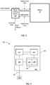
- FIGS. 1-3 Block diagrams of some example devices and systems are shown in FIGS. 1-3 .
- blood may be removed from a patient 10 and fluid may be removed via a blood fluid removal device 100 and returned to the patient 10. Removed fluid may be diverted.
- the blood fluid removal device 100 or system, or components thereof, are implanted, the removed fluid may be diverted to the patient's bladder.
- Examples of blood fluid removal devices 100 that may operate as depicted in FIG. 1 are ultrafiltration and hemofiltration devices. Examples of such devices and components thereof that may be employed in accordance with the teachings presented herein are well known in the art. It will be understood that peritoneal dialysis, where dialysate is introduced into the peritoneal cavity, may also be employed.
- replacement fluid may be introduced into the patient's blood if fluid is removed from the blood by the device 100 at too great a rate or amount.
- the replacement fluid may be added to the original blood before fluid removal or may be added to the blood after initial fluid removal and prior to return to the patient's cardiovascular system.
- the replacement fluid is added after initial fluid removal.
- the pH and electrolyte concentration of the replacement fluid may be set or adjusted, e.g. as described in more detail below, based on monitoring of pH or electrolytes of the patient.
- the blood fluid removal device 100 may employ dialysate to assist in removal of contaminants from the patient's blood and in maintaining proper pH and electrolyte balance.
- the pH or electrolyte concentration of the dialysate may be set or adjusted, e.g. as described in more detail below, based on monitoring of pH or electrolytes.
- Used dialysate and fluid removed from the blood may be diverted.
- the used dialysate and removed fluid, or a portion thereof may be regenerated (indicated by dashed lined regeneration system 150 ) to produce fresh dialysate for re-use in the blood fluid removal process.
- REDY regenerative dialysis
- Nephrology 4:275-278, 1998 which system may be employed or readily modified for use in embodiments described herein.
- a concentrate may be added to the regenerated dialysate to adjust the pH and electrolytes of the regenerated dialysate to an amount suitable for re-use as fresh dialysate.
- systems and devices that operate in a manner shown in the embodiment of FIG . 2 include hemodialysis and hemodiafiltration systems. Examples of such devices and components thereof that may be employed in accordance with the teachings presented herein are well known in the art. It will be understood that peritoneal dialysis, where the dialysate is introduced into peritoneal cavity may also be employed.
- replacement fluid may be introduced into the patient's blood, upstream or downstream of fluid removal, e.g. as described above with regard to FIG. 1 .
- the blood pH and electrolyte concentrations are within suitable ranges. If blood electrolyte concentrations are not within suitable ranges, problems with cardiac contractility, efficiency and the like may occur. If the pH is not within a suitable range, acidosis may result, which can result in disruption of cell membranes and denaturation of proteins. In either case, if ranges of blood electrolytes and pH are not properly controlled, the patient's health may be at risk. For example, sudden and cardiac death (including death from congestive heart failure, myocardial infarction, and sudden death) are common in hemodialysis patients. See Bleyer et al, "Sudden and cardiac death rated in hemodialysis patients," Kidney International, (1999), 55:1552-1559 .
- one goal of hemodialysis, ultrafiltration, and the like is to ensure that the patient's blood pH and electrolyte concentrations are within acceptable ranges.
- Typical ranges of pH and blood electrolyte concentration that are desired during or following a blood fluid removal session are provided in Table 1 below.
- concentrations of various acids or bases are often important in determining the pH of blood. Accordingly, some typical target concentrations of such acids, bases are presented in Table 1.
- Table 1 Typical target ranges for pH and electrolytes (ref.
- the target for a particular patient may be different from the values presented in Table 1 for one or more electrolyte or pH. It will also be understood that buffers are typically employed to maintain proper blood pH.
- buffers that may be used in fluid, such as replacement fluid or dialysate, include bicarbonate, acetate, citrate, lactate, amino acid and protein buffers.
- concentration and composition of the buffers and components thereof may be adjusted based on monitored pH of the patient's blood.
- concentration of electrolytes such as sodium, potassium, calcium, and chloride in replacement fluid or dialysate may be set or altered based the monitored levels of electrolytes.
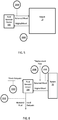
- FIG . 4 a block diagram showing some components that a sensing device 200 may include is depicted.
- the sensing device 200 is shown as a stand-alone device in FIG . 4 , but it will be understood that the device, or one or more components thereof, may be incorporated into other devices, such as a blood fluid cleaning device.
- the sensor 200 depicted in FIG . 4 has a housing 299 (which can be shared with another device if the sensor, or portion thereof, is incorporated into the other device) for containing various electronic components 296 , 297 , 289 , 295.
- Sensing circuitry 296 such as analog-to-digital convertor, band-pass filter, or the like, is operably coupled to power supply 297(which, again may be shared) and control electronics 295 (which may be shared), which include a processor 294 and a memory 293 for storing sensed data and processor instructions. Sensing circuitry 296 is also operably coupled to transducer 205 , such as an ion selective electrode, via lead 207 . In some embodiments (not shown), the device 200 is leadless, and the transducer 205 or ion selective electrode is exposed through housing 299 . Control electronics 295 are operably coupled to power supply 297 and to communication circuitry 289 for communicating with another device external. In cases where the sensor 200 is a stand-alone device, communication circuitry may be used to communicate with a blood fluid removal device or a device in communication with a blood fluid removal device to transmit data acquired from the sensor to the blood fluid removal device.
- the transducer is an ion selective electrode configured to detect H + ions, K + ions, Na + ions, Ca 2+ ions, Cl - ions, phosphate ions, magnesium ions, acetate ions, amino acids ions, or the like.
- Such electrodes, and components of sensors employing such electrodes are known in the art and may be employed, or modified to be employed, for use in the monitoring described herein.
- a pH sensor is Medtronic, Inc.'s Bravo® pH sensor.
- One example of a potassium selective electrode is the Thermo Scientific Potassium Ionplus®.
- Other examples of ion-selective electrodes are contained in the CCX Stat Profile® produced by Nova Biomedical.
- one or more sensors are employed to detect one or more ions to gauge pH or electrolytes in the blood.
- a sensor may have more than one transducer, even if leadless, that may monitor more than one ionic species. By measuring more than one ionic species, a more detailed understanding of the levels of various electrolytes or blood components may be had. For example, in some patients in some situations, one electrolyte may be at elevated levels while another may be at reduced levels.
- more than one sensor for the same ion is employed for purposes of result confirmation and redundancy, which can improve reliability and accuracy.
- sensors for the same ion may be configured to accurately detect different ranges of concentrations of the ion.
- more than one transducer is present in a single unit. This allows for convenient data collection and circuitry, as all the data may be collected in one place at the same time. Further, the multiple transducers may share the same fluid collection mechanism (e.g., a microdialyzer in the case of an implant), and if needed or desired, may share the same data processing and memory storage components.
- a fluid collection mechanism e.g., a microdialyzer in the case of an implant
- a sensor may be placed at any suitable location for purposes of monitoring electrolytes or pH.
- a sensor or transducer
- a pH or electrolyte sensor 200A may be located external to the patient 10 and configured to monitor pH or electrolyte levels in the blood before the blood enters the blood fluid removal device 100 (or before entering blood fluid removal medium, as will be discussed below in more detail).
- sensor 200A may be positioned such that a transducer is placed within a catheter carrying blood from the patient 10 to the blood fluid removal device 100 or blood fluid removal media.
- Data acquired from a sensor 200A upstream of the fluid delivery device 100 or blood fluid removal media provides an indication of the actual status of the patient 10.
- data acquired from a sensor 200A upstream of the fluid delivery device 100 or medium can be used to determine whether blood pH and electrolytes are approaching target ranges or to determine the rate at which pH and electrolytes are changing in the patient as a result of the blood fluid removal process. While not intending to be bound by theory, it is possible that too rapid of a change in pH or electrolyte concentrations can lead to patient hypotension or sudden death that is seen in patient populations that undergo blood fluid removal processes. By monitoring and controlling the rate of change of pH or electrolyte changes in the blood of a patient during the blood fluid removal session, perhaps the incidence of crashing or sudden death can be reduced.
- a sensor 200B is located external to the patient 10 and configured to monitor pH or electrolyte levels in the blood after the blood exits the blood fluid removal device 100 (or after exiting the blood fluid removal medium) and before being returned to the patient 10.
- sensor 200B may be positioned such that a transducer is placed within a catheter carrying blood from the blood fluid removal device 100 (or medium) to the patient 10.
- Such a downstream sensor 200B may be used to ensure that pH and electrolyte levels of blood to be returned to the patient are not out of range.
- the system employs both an upstream sensor 200A and a downstream sensor 200B.
- the pH or electrolyte levels detected upstream and downstream may be compared, and the compared data may be used to adjust the pH or electrolyte concentration or composition of fluid employed during a blood fluid removal session.
- the compared data may also be used to determine the rate of change of blood electrolyte concentration or pH.
- the patient prior to a blood fluid removal session or in the early parts of such a session, the patient is typically fluid over-loaded and the concentration of electrolytes may be low (due to the increased fluid volume). It may be appropriate to allow a slightly higher than target concentration electrolyte to be introduced back into the patient when the patient's electrolyte levels are low.
- the electrolyte levels in the returned blood should within target range. Monitoring both upstream and downstream will allow for adjustments and checks on progress that may not be attainable by monitoring only one or the other.
- FIG. 6 a system employing sensors 200B, 200C, 200D, 200E in alternative or additional locations is shown. Any one or more of such sensors 200B, 200C, 200D, 200E may be employed. The system also employs the downstream sensors as described with regard to FIG. 5 , but are not shown in FIG. 6 . A brief discussion of some possible configurations and uses of sensors 200B, 200C, 200D, 200E is provided herein. However, it will be understood that meaningful data may be obtained from configurations other than those described below.
- the system (e.g., the system depicted in FIG . 6 ) employs two upstream sensors 200B , 200C .
- the first upstream sensor 200B is positioned to monitor pH or electrolyte levels in the blood after it exits the blood fluid removal device 100 or medium but before replacement fluid is added.
- the second sensor 200C is positioned to monitor pH or electrolyte levels of the blood after the replacement fluid is added and before the blood is returned to the patient 10.
- the first sensor 200B may be used to determine what adjustments may be needed to pH and electrolyte levels, and the second sensor 200C may be used to verify that the appropriate adjustments were made to achieve the desired pH and electrolyte concentrations prior to returning the blood to the patient.
- the system employs a sensor 200E to monitor pH or electrolytes removed from the blood of the patient after exiting the blood fluid removal device 100 or medium, and may include a sensor 200D configured and positioned to monitor pH or electrolytes of fluid (in the depicted case, dialysate) prior to entering the blood fluid device 100 or medium.
- a sensor 200E configured and positioned to monitor pH or electrolytes of fluid (in the depicted case, dialysate) prior to entering the blood fluid device 100 or medium.
- the pH or levels of electrolytes (or change in pH or electrolytes) exiting the device 100 or medium may be used to predict the blood pH and electrolyte levels without having to measure the levels in the blood directly.
- data acquired from the sensors may be used to adjust the pH or electrolyte concentrations of fluid (e.g. dialysate or replacement fluid) used during the dialysis session.
- fluid e.g. dialysate or replacement fluid
- concentrations of dialysate or replacement fluid are varied and the patient's response to the varying concentrations, as measured by one or more of sensors, is used to determine how best to proceed with further adjustments.
- the system may be configured to learn what works best for the particular patient 10. For example, dialysate or replacement fluid having different buffer concentrations or compositions or different electrolyte concentrations may be used during an initial blood fluid session or early in a blood fluid session.
- the patient's response to these different fluids can be monitored via sensors, and the system can learn what works best for the patient. For example, the system can determine whether the use of the different fluids resulted in the patient's blood levels approaching target levels or deviating from target levels, as well as the rate at which the levels approach or deviate from target ranges. Based on the initial sessions or stages, the system may begin to predict how to react to a particular monitored pH or electrolyte level for the patient and adjust the fluid pH and electrolyte concentrations accordingly.
- the pH and electrolyte concentration of the fluid may be adjusted in any suitable manner.
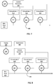
- FIGS. 7-8 some representative components of an example of a closed-loop system ( FIG.7 ) and an open-loop system ( FIG . 8 ) for adjusting pH and electrolyte concentrations of fluid are shown.
- FIG. 7 data from one or more sensor 200 is presented to control electronics 495 , which are configured to control flow control elements 415 , 425 , 435 , such as valves.
- the electronically controllable flow control elements 415 , 425 , 435 are in fluid communication with supplies of concentrated electrolyte or buffer solutions 410 , 420 , 430 and with fluid line 440 , which may be a catheter for carrying fresh dialysate or a catheter for carrying replacement fluid.
- the electronically controllable flow control elements 415 , 425 , 435 via control electronics 495 , control the rate at which the concentrates 410 , 420 , 430 flow into the fluid line 440 .
- the concentrates 410 , 420 , 430 are added to bulk fluid 400 to adjust the concentration of electrolytes or the pH of the bulk fluid (and thus the blood).
- data from one or more sensor 200 may be processed and appropriate information presented on a display 600 , which may be a part of the blood fluid removal device, a separate computer, or the like.
- a healthcare provider may use the information presented on the display 600 to adjust the concentration of electrolytes or pH. This can be done, for example, by transmitting appropriate instructions to the control electronics via an input device 500 .
- Any suitable input device 500 may be used.
- input device 500 may be a keyboard, a computer, a tablet, a personal data assistant, a physician programmer, or the like.
- the input device 500 is the display 600 ; e.g., where the display 600 is a touch screen device.
- the control electronics 495 can control flow control elements 415 , 425 , 435 to control the amount of concentrate 410 , 420 , 430 introduced to bulk fluid 400 , which is dialysate fluid.
- any number of suitable concentrates may be used.
- one concentrate may be sufficient with higher amounts being added when the electrolytes are determined to be low in the patient's blood, and smaller amounts being added when the electrolytes are determined to be high in the patient's blood.
- More than one concentrate may be used when it is desired to, for example, control pH and electrolyte concentration independently or to control concentration of different electrolytes independently.
- the number of concentrates is the same as the number of ion species (pH and electrolytes) monitored.
- Control elements 415 , 425 , 435 may be any suitable control element, such as electronically controllable valves, electronically controllable pump mechanisms, or the like.
- Any suitable system may be configured as depicted in FIGS. 7-8 to provide control of adjustment of pH or electrolytes based on data acquired from one or more sensors.
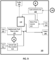
- FIGS. 9- 10 selected components of two example systems are illustrated in FIGS. 9- 10.
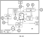
- the system in FIG. 9 illustrates control of flow of a concentrate into replacement fluid and is therefore not part of the invention, and the system in FIG. 10 illustrates control of flow of a concentrate into dialysate.
- the depicted device 100 includes a fluid pathway for adding replacement fluid to blood before it is returned to the patient.
- the device 100 includes an inlet 110 for receiving blood from the patient and an outlet 140 for returning blood to the patient.
- a blood flow control element 120 In the flow path between the inlet 110 and outlet 140 are a blood flow control element 120 and a medium for removing fluid and contaminants from the blood.
- the blood flow control element 120 is operably coupled to control electronics 150 which provide instructions to control the rate at which blood is passed through medium 130. Fluids and contaminants removed from the blood by the medium 130 may exit via outlet 180.
- the device 100 depicted in FIG. 9 also includes an inlet 197 for receiving bulk replacement fluid and a replacement fluid flow control element 195 in communication with the inlet and configured to control the rate at which the replacement fluid is added to the blood.
- the control electronics 150 are operably coupled to the replacement fluid flow control element 195 and are configured to control the rate at which replacement fluid flow control element 195 adds fluid to the blood.
- the device 100 also includes (i) an inlet 401 for receiving a concentrate for adjusting the pH or electrolyte concentration of the bulk replacement fluid, and (ii) a concentrate flow control element 415 in communication with the inlet 401 and configured to control the rate at which the concentrate is added to the replacement fluid or blood before the blood is returned to the patient.
- the concentrate is added to the replacement fluid prior to the replacement fluid being added to the blood (as depicted) so that the concentrate may be mixed or diluted prior to being added to the blood.
- the device may include a mixer (not shown) to mix the concentrate and bulk replacement fluid prior to adding to the blood.
- control electronics 150 are operably coupled to the concentrate flow control element 415 and are configured to control the rate at which the concentrate flow control element 415 adds fluid to the replacement fluid or blood based on data received from one or more sensors 200 that monitor pH or electrolytes levels (e.g., as described above). By controlling the rate at which the concentrate is introduced into replacement fluid or blood, the concentration or pH (or buffering capacity) of the returned blood can be controlled.
- the device has an inlet 110 for receiving blood from a patient, a blood flow control element 120 in communication with the inlet 110 and configured to control the rate at which blood flows through medium 130 for removing fluid and contaminates from the blood.
- the device also includes an outlet 140 in communication with the medium 130 for returning blood to the patient.
- the medium 130 component has a housing 139 defining a major chamber 131.
- a semipermeable filter 135 such as a hemodialysis or hemodiafiltration membrane filter, sealingly divides the major chamber into two minor chambers 133 , 137 ; one 133 for blood flow and the other 137 for dialysate flow (as well as fluid and waste that passes through the filter 135 from the blood)
- dialysate is regenerated by passing through dialysate regeneration medium 402 or components, such REDY regeneration medium and components, or the like, to regenerate bulk dialysate.
- the device also has an outlet 180 in communication with the medium 130 for diverting fluid removed from the blood out of the device.
- a flow regulator element 700 such as a valve, is operably coupled to control electronics 150 and is disposed in the flow path between the medium 130 and the outlet 180 to control the amount of fluid that exits the device (as a portion of the fluid is regenerated).
- the regeneration media or components ( 402 ) remove much of the pH buffer or electrolytes from the dialysate.
- a concentrate containing concentrated electrolytes and pH buffers is added to the regenerated dialysate before the dialysate re-enters the medium 130.
- a sensor 299 is positioned downstream of the regeneration medium 402 to monitor a level of a component of the regenerated dialysate.
- the sensor 299 may be a pH or electrolyte sensor and data acquired from sensor 299 may be used in determining how much concentrate to add to the regenerated fluid (which data may be provided to control electronics 150 ).
- the sensor 299 may be a sensor that monitors a blood waste product, such as urea, to determine whether the regeneration media 402 is properly functioning. Increased or detectable levels of a waste product may indicate that the regeneration media 402 or components may need replacement or regeneration.
- the concentrate 410 is stored in a reservoir 410 , having an inlet 401 that allows the concentrate supply in the reservoir 410 to be replenished from time to time.
- the rate at which the concentrate is added to the regenerated dialysate is controlled by concentrate flow control element 415 , which is operably coupled to control electronics 150 , and is based on data received from sensor 200 that monitors pH or electrolyte concentrations (e.g., as described above).
- the device 100 in FIG. 10 also has a dialysis flow control element 170 for controlling the rate at which dialysis is introduced into the dialysis flow compartment of the medium 130 .
- the device 100 also includes a negative pressure control element 190 in communication with the dialysate compartment of the medium component 130 .
- the negative pressure control element 190 which may include a pump or the like, may be used to generate or change a pressure differential across the membrane to control the rate at which fluid is removed from blood that passes though the medium component 130 .
- the control electronics 150 which may include a processor, memory, etc., are operably coupled to, and configured to control, the blood flow control element 120 , the dialysis flow control element 170 , and the negative pressure control element 190 . By controlling these elements in a coordinated manner, the rate at which fluid is removed from blood may be controlled. It will be understood that a device 100 need not have all of the controllable elements ( 120 , 170 , 190 ) depicted in FIG . 10 to effectively control rate of fluid removal from blood.
- any suitable control element may be used for the various control elements ( 120 , 150 , 170 , 195 , 415 ) depicted in FIGS. 9-10 .
- a variable or adjustable rate pump may be employed.
- a series of electronically controllable valves may be employed.
- the valves are in communication flow paths having differing flow resistances.
- FIGS. 9-10 depict components as being within a single unit, it will be understood that one or more of the components may be housed in separate units.
- the control electronics, or a portion thereof may be housed in a separate device, such as a computer, tablet, physician programmer, or the like.
- the computer, tablet, etc. may receive input from sensors, determine appropriate action to take, and instruct appropriate components of a blood fluid removal device to take the appropriate action.
- blood fluid removal devices and systems, and components thereof, described herein are presented for purposes of illustration and not limitation. Components, devices and systems other than those described herein, or derivations of the components, devices and systems described herein, may be employed. Further, components of the devices depicted and discussed above may be interchanged, substituted or added to components of alternative embodiments, as appropriate. Further, it will be understood that, while many of the blood fluid removal devices depicted in a variety of the figures, such as FIGS. 1-3 and 5-6 , are shown as external to the patient, the teachings presented herein apply if the device, or components thereof, were implanted in the patient.
- FIGS. 11-13 may be used to carry out the uses depicted in FIGS. 11-13 and described below, or portions thereof.
- any suitable device or system may be employed to carry out the uses, or portions thereof, described below. It will be understood that various steps of the uses presented with regard to any one of FIGS. 11-13 below may be interchanged, substituted, or added to steps presented with regard to any other of FIGS. 11-13 .
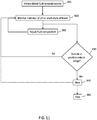
- the depicted use includes initiating a blood fluid removal session ( 801 ) and monitoring an indicator pH or electrolyte concentration of blood ( 810 ); e.g. detecting pH or electrolytes in blood or in fluid from which pH or electrolyte levels in blood can be derived.
- the pH or electrolyte composition or concentration of fluid used in the blood fluid removal session may be adjusted ( 860 ). For example, based on one or more of the current value of a monitored ionic species or the rate of change in the monitored ionic species, the fluid composition may be adjusted, e.g. as discussed above.
- continuous, periodic or intermittent determinations may be made as to whether the pH or electrolyte concentration is out of range ( 830 ) based on data acquired during the monitoring ( 810 ). For example, a determination ( 830 ) may be made as to whether pH or electrolyte levels crossed a threshold (e.g., a ceiling or floor). If the pH or electrolytes are determined to be within range, monitoring ( 810 ) may continue. If the pH or electrolytes are determined to be out of range (e.g., cross a threshold), an alert ( 840 ) may be issued to notify the patient or a healthcare provider of the situation.
- a threshold e.g., a ceiling or floor
- the situation may warrant stopping ( 890 ) of the blood fluid removal session; e.g., if the detected pH or electrolytes are too far out of range or cross a heightened threshold. In other cases, it may be suitable to continue with the blood fluid removal session with heightened awareness of a situation for which increased attention may be warranted.
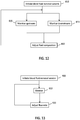
- the depicted use includes initiating a blood fluid removal session ( 801 ) and monitoring an indicator pH or electrolyte concentration upstream ( 815 ) and downstream ( 813 ) of blood fluid removal. Data acquired from upstream and downstream sensors may be compared to determine how to adjust ( 860 ) the fluid composition, e.g. as described above.
- the depicted use shows a use where blood electrolyte concentration or pH is adjusted by altering the flow rate of dialysate or blood.
- the use includes initiating a blood fluid removal session ( 900 ), such as a hemodialysis session, and monitoring an indicator of pH or electrolyte ( 910 ), which can be in the patient, upstream of the device, downstream of the device, within the device, or the like. Based on the monitored data ( 910 ), adjustments to the flow of dialysate or blood may be made ( 920 ) to adjust the electrolyte concentration or pH in the blood that gets returned to the patient.
- a blood fluid removal session such as a hemodialysis session
- an indicator of pH or electrolyte 910
- adjustments to the flow of dialysate or blood may be made ( 920 ) to adjust the electrolyte concentration or pH in the blood that gets returned to the patient.
- the uses described herein, including the uses depicted in FIGS. 11-13 may be carried out by sensor devices, blood fluid removal devices, or other devices in communication with sensor devices or blood fluid removal devices. These uses may be algorithms or instructions programmed into memory of such devices, which may be carried out by processors or other control electronics of the devices. Preferably, the processor is in communication with appropriate control elements of the devices and is configured to control such elements in a manner such that the programmed instructions are carried out by the appropriate device. It will be understood that a computer readable medium programmed with instructions that cause a sensor device, blood fluid removal device, or other suitable device to carry out a use, or a portion thereof, as described herein are contemplated. The computer readable medium may be non-transitory, i.e. lasting for more than a fleeting instant or seconds. The medium may be memory, such as RAM or ROM, a cd or dvd, flash memory, or the like.
Description
- This application claims priority to
U.S. Utility Application No. 13/424,479 filed March 20, 2012 U.S. Provisional Application No. 61/480,539 U.S. Provisional Application No. 61/480,544 U.S. Provisional Application No. 61/480,541 U.S. Provisional Application No. 61/480,535 U.S. Provisional Application No. 61/480,532 U.S. Provisional Application No. 61/480,530 U.S. Provisional Application No. 61/480,528 - The present disclosure relates generally to devices and systems for monitoring indicators of electrolytes or pH in patients for which blood cleaning or fluid removal is indicated, such as patients suffering from kidney disease or heart failure.
- Patients who undergo hemodialysis or other procedures that remove solutes and fluid from the blood often die of cardiac complications. Many factors may contribute to such death, including stress placed on the heart due to the increased blood fluid volume in these patients. Increased fluid concentrations and inability to remove waste products from the blood, in some cases, can also contribute to electrolyte and pH imbalance that can affect cardiac contractility and efficiency. Further, rapid changes in fluid volume or pH or electrolyte concentration of the blood during hemodialysis or other fluid removal processes may place additional stress on the heart and may contribute to the high rate of morbidity for patients who undergo blood fluid removal procedures.
- When a patient reaches a point where routine blood fluid removal procedures are prescribed, the patient undergoes periodic examinations that allow a healthcare provider to set various parameters of the blood fluid removal procedures, such as the profile of fluid removal, the composition of dialysate or replacement fluid employed, and the like. These examinations typically occur once a month in accordance with current standards of care.
- Hemodialysis or similar procedures may occur three to four times a week. Thus, the patient may undergo 10 to 15 or more blood fluid removal sessions before the prescription or parameters are changed. It is possible, for example, that a prescription with regard to a dialysate electrolyte and pH buffer composition will not be appropriate for a patient several days or weeks after the prescription is set. Accordingly, it may be desirable to more frequently determine whether the electrolyte or pH concentration of a fluid used in blood fluid removal sessions is appropriate, In addition, it may be desirable to adjust the concentration or composition of the fluid during a blood fluid removal session in a manner that may improve patient health and reduce morbidity.
-
- This disclosure, among other things, describes devices, systems and uses for monitoring indicators of pH or electrolytes in patients for which blood fluid removal sessions are indicated. The monitoring may occur during a blood fluid removal session, and the concentration or composition of buffer or electrolytes may be adjusted based on monitored data acquired during the blood fluid removal session. By monitoring pH or electrolytes, the dialysate of replacement fluid may be adjusted during a session to enhance patient safety. The invention is a system as defined by
claim 1. - Also described is a use including initiating a blood fluid removal procedure for a patient in need thereof. The procedure includes use of a fluid selected from a dialysate fluid or a replacement fluid. The fluid has an initial pH buffer composition or electrolyte composition. The use further includes monitoring an indicator of blood electrolyte concentration or blood pH of the patient during the blood fluid removal session, and adjusting the pH buffer composition or the electrolyte composition of the fluid based on a value of the monitored indicator. The monitoring may be of blood before or after the blood has passed through the blood fluid removal device, or may be of fluid removed from the blood. In some embodiments, data acquired from monitoring performed on blood before and after passing through the blood fluid removal device is compared to data acquired from fluid (e.g., dialysate) before and after passing through blood fluid removal media of the device, and based on the comparison, the pH buffer composition or the electrolyte composition of the fluid is adjusted.
- One or more embodiments of the systems, devices and uses described herein may provide one or more advantages over prior systems, devices and uses for blood fluid removal in patients. Such advantages will be apparent to those skilled in the art upon reading the following detailed description.
- The accompanying drawings, which are incorporated into and form a part of the specification, illustrate several embodiments of the present disclosure and, together with the description, serve to explain the principles of the disclosure. The drawings are only for the purpose of illustrating embodiments of the disclosure and are not to be construed as limiting the disclosure.
-
FIGS. 1-3 are schematic block diagrams showing interaction of blood fluid removal devices with a patient showing flow of blood (dashed arrows) and fluid (solid arrows), which blood fluid removal devices may be used in various embodiments described herein. -
FIG. 4 is a schematic block diagram showing some selected components of an embodiment of a sensor device. -
FIGS. 5-6 are schematic block diagrams showing sensors and blood flow between patients and a blood fluid removal devices. -
FIGS. 7-8 are schematic block diagrams showing flow paths and some control mechanisms (closed loop:FIG. 7 ; open loop:FIG. 8 ) for controlling flow of concentrate into fluid for use in a blood fluid removal process based on monitored pH or electrolytes. -
FIGS. 9-10 are schematic block diagrams of some components of blood fluid removal devices that are configured to adjust pH or electrolyte concentrations of fluids in response to data regarding monitored pH or electrolyte levels in blood. -
FIGS. 11-13 are flow diagrams illustrating overviews of general uses in accordance with embodiments described herein. - The schematic drawings presented herein are not necessarily to scale. Like numbers used in the figures refer to like components, steps and the like. However, it will be understood that the use of a number to refer to a component in a given figure is not intended to limit the component in another figure labeled with the same number. In addition, the use of different numbers to refer to components is not intended to indicate that the different numbered components cannot be the same or similar.
- In the following detailed description, reference is made to the accompanying drawings that form a part hereof, and in which are shown by way of illustration several embodiments of devices, systems and uses. It is to be understood that other embodiments are contemplated and may be made without departing from the scope of the present invention as defined by the claims. The following detailed description, therefore, is not to be taken in a limiting sense.
- All scientific and technical terms used herein have meanings commonly used in the art unless otherwise specified. The definitions provided herein are to facilitate understanding of certain terms used frequently herein and are not meant to limit the scope of the present disclosure.
- As used in this specification and the appended claims, the singular forms "a", "an", and "the" encompass embodiments having plural referents, unless the content clearly dictates otherwise.
- As used in this specification and the appended claims, the term "or" is generally employed in its sense including "and/or" unless the content clearly dictates otherwise.
- As used herein, "have", "having", "include", "including", "comprise", "comprising" or the like are used in their open ended sense, and generally mean "including, but not limited to."
- As used herein, a "patient for which a blood fluid removal session is indicated" is a patient that has undergone, is undergoing, or is likely to undergo at least one blood fluid removal session. In general, such patients are fluid overloaded patients, such as patients suffering from heart failure, chronic kidney disease, or acute kidney failure. Often such patients are
stage 3 to stage 5 chronic kidney disease patients, are unresponsive or under-responsive to diuretics, or the like. - As used herein, a "blood fluid removal process," or the like, refers to a process from which fluid is removed from blood of a patient and the blood is returned to the patient. In most cases, the blood is also cleaned; i.e., waste products are removed from the blood and cleaned blood is returned to the patient. Examples of blood fluid removal processes include ultrafiltration, hemofiltration, hemodialysis, hemodiafiltration, peritoneal dialysis, and the like. Any patient for which blood fluid removal is indicated may benefit from the devices, systems and uses described herein.
- This disclosure relates to, among other things, systems and uses for monitoring indicators of pH or electrolyte concentrations in patients for which a blood fluid removal process is indicated. In embodiments, the sensors are configured and positioned to monitor pH or electrolytes in one or more of (i) blood of the patient before the blood enters a fluid removal or cleaning medium of the blood fluid removal device; (ii) blood of the patient before after blood exits the medium before being returned to the patient; (iii) fluid removed from the blood of the patient after passing through the medium; (iv) fluid, such as dialysate, before entering the medium; (v) fluid upstream or downstream of the addition of a concentrate for use in altering the composition of the fluid (e.g., dialysate or replacement fluid); (vi) or the like. Additional discussion with regard to sensor placement and use of such sensors will follow. First, however, a brief discussion of blood fluid removal devices or systems that may be used in accordance with the teachings presented herein is presented.
- Any suitable device or system for removing fluid, or fluid and contaminants, from blood may be used in accordance with the teachings presented herein. The devices, or components thereof, may be traditional large counsel-type, wearable, or implantable.
- Block diagrams of some example devices and systems are shown in
FIGS. 1-3 . As shown inFIG. 1 , blood may be removed from apatient 10 and fluid may be removed via a bloodfluid removal device 100 and returned to thepatient 10. Removed fluid may be diverted. In some embodiments where the bloodfluid removal device 100 or system, or components thereof, are implanted, the removed fluid may be diverted to the patient's bladder. Examples of bloodfluid removal devices 100 that may operate as depicted inFIG. 1 are ultrafiltration and hemofiltration devices. Examples of such devices and components thereof that may be employed in accordance with the teachings presented herein are well known in the art. It will be understood that peritoneal dialysis, where dialysate is introduced into the peritoneal cavity, may also be employed. - With some of such devices, replacement fluid may be introduced into the patient's blood if fluid is removed from the blood by the
device 100 at too great a rate or amount. The replacement fluid may be added to the original blood before fluid removal or may be added to the blood after initial fluid removal and prior to return to the patient's cardiovascular system. Preferably, the replacement fluid is added after initial fluid removal. The pH and electrolyte concentration of the replacement fluid may be set or adjusted, e.g. as described in more detail below, based on monitoring of pH or electrolytes of the patient. - As shown in the embodiment depicted in
FIG. 2 , the bloodfluid removal device 100 may employ dialysate to assist in removal of contaminants from the patient's blood and in maintaining proper pH and electrolyte balance. The pH or electrolyte concentration of the dialysate may be set or adjusted, e.g. as described in more detail below, based on monitoring of pH or electrolytes. Used dialysate and fluid removed from the blood may be diverted. In some embodiments, particularly where the bloodfluid removal device 100 or system or components thereof are wearable or implantable, the used dialysate and removed fluid, or a portion thereof, may be regenerated (indicated by dashed lined regeneration system 150) to produce fresh dialysate for re-use in the blood fluid removal process. One system for regeneration of dialysate is the REDY system, such as described in Roberts, M, "The regenerative dialysis (REDY) sorbent system," Nephrology 4:275-278, 1998, which system may be employed or readily modified for use in embodiments described herein. As shown inFIG. 2 , a concentrate may be added to the regenerated dialysate to adjust the pH and electrolytes of the regenerated dialysate to an amount suitable for re-use as fresh dialysate. - Regardless of whether the dialysate is regenerated, systems and devices that operate in a manner shown in the embodiment of
FIG. 2 include hemodialysis and hemodiafiltration systems. Examples of such devices and components thereof that may be employed in accordance with the teachings presented herein are well known in the art. It will be understood that peritoneal dialysis, where the dialysate is introduced into peritoneal cavity may also be employed. - As shown in
FIG. 3 , in cases where the bloodfluid removal device 100 ofFIG. 2 removes fluid from the blood at too high a rate, replacement fluid may be introduced into the patient's blood, upstream or downstream of fluid removal, e.g. as described above with regard toFIG. 1 . - Regardless of the device or blood fluid removal process employed, it is important to ensure that the blood pH and electrolyte concentrations are within suitable ranges. If blood electrolyte concentrations are not within suitable ranges, problems with cardiac contractility, efficiency and the like may occur. If the pH is not within a suitable range, acidosis may result, which can result in disruption of cell membranes and denaturation of proteins. In either case, if ranges of blood electrolytes and pH are not properly controlled, the patient's health may be at risk. For example, sudden and cardiac death (including death from congestive heart failure, myocardial infarction, and sudden death) are common in hemodialysis patients. See Bleyer et al, "Sudden and cardiac death rated in hemodialysis patients," Kidney International, (1999), 55:1552-1559.
- Accordingly, one goal of hemodialysis, ultrafiltration, and the like is to ensure that the patient's blood pH and electrolyte concentrations are within acceptable ranges. Typical ranges of pH and blood electrolyte concentration that are desired during or following a blood fluid removal session are provided in Table 1 below. As indicated in Table 1, concentrations of various acids or bases (or salts or hydrates thereof) are often important in determining the pH of blood. Accordingly, some typical target concentrations of such acids, bases are presented in Table 1.
Table 1: Typical target ranges for pH and electrolytes (ref. Medical Surgical Nursing, 7th Ed., 2007) Target Range pH 7.35 - 7.45 Phosphate 2.8 - 4.5 mg/dL Bicarbonate 22 - 26 mEq/L Cl- 96 - 106 mEq/L Mg2+ 1.5 - 2.5 mEq/L Na+ 135 - 145 mEq/L K+ 3.5 - 5.0 mEq/L Ca2+ 4.5 - 5.5 mEq/L - However, it will be understood that the target for a particular patient may be different from the values presented in Table 1 for one or more electrolyte or pH. It will also be understood that buffers are typically employed to maintain proper blood pH.
- Some suitable buffers that may be used in fluid, such as replacement fluid or dialysate, include bicarbonate, acetate, citrate, lactate, amino acid and protein buffers. The concentration and composition of the buffers and components thereof may be adjusted based on monitored pH of the patient's blood. Similarly, the concentration of electrolytes such as sodium, potassium, calcium, and chloride in replacement fluid or dialysate may be set or altered based the monitored levels of electrolytes.
- Any suitable sensor may be employed to monitor pH or electrolytes. For example and referring to
FIG. 4 , a block diagram showing some components that asensing device 200 may include is depicted. Thesensing device 200 is shown as a stand-alone device inFIG. 4 , but it will be understood that the device, or one or more components thereof, may be incorporated into other devices, such as a blood fluid cleaning device. Thesensor 200 depicted inFIG. 4 has a housing 299 (which can be shared with another device if the sensor, or portion thereof, is incorporated into the other device) for containing variouselectronic components Sensing circuitry 296, such as analog-to-digital convertor, band-pass filter, or the like, is operably coupled to power supply 297(which, again may be shared) and control electronics 295 (which may be shared), which include aprocessor 294 and amemory 293 for storing sensed data and processor instructions.Sensing circuitry 296 is also operably coupled totransducer 205, such as an ion selective electrode, vialead 207. In some embodiments (not shown), thedevice 200 is leadless, and thetransducer 205 or ion selective electrode is exposed throughhousing 299.Control electronics 295 are operably coupled topower supply 297 and tocommunication circuitry 289 for communicating with another device external. In cases where thesensor 200 is a stand-alone device, communication circuitry may be used to communicate with a blood fluid removal device or a device in communication with a blood fluid removal device to transmit data acquired from the sensor to the blood fluid removal device. - Any suitable transducer may be employed to detect pH or electrolytes. In embodiments, the transducer is an ion selective electrode configured to detect H+ ions, K+ ions, Na+ ions, Ca2+ ions, Cl- ions, phosphate ions, magnesium ions, acetate ions, amino acids ions, or the like. Such electrodes, and components of sensors employing such electrodes, are known in the art and may be employed, or modified to be employed, for use in the monitoring described herein. One example of a pH sensor is Medtronic, Inc.'s Bravo® pH sensor. One example of a potassium selective electrode is the Thermo Scientific Potassium Ionplus®. Other examples of ion-selective electrodes are contained in the CCX Stat Profile® produced by Nova Biomedical.
- In some embodiments, one or more sensors are employed to detect one or more ions to gauge pH or electrolytes in the blood. In some embodiments, a sensor may have more than one transducer, even if leadless, that may monitor more than one ionic species. By measuring more than one ionic species, a more detailed understanding of the levels of various electrolytes or blood components may be had. For example, in some patients in some situations, one electrolyte may be at elevated levels while another may be at reduced levels. In some embodiments, more than one sensor for the same ion is employed for purposes of result confirmation and redundancy, which can improve reliability and accuracy. In some embodiments, sensors for the same ion may be configured to accurately detect different ranges of concentrations of the ion. In embodiments, more than one transducer is present in a single unit. This allows for convenient data collection and circuitry, as all the data may be collected in one place at the same time. Further, the multiple transducers may share the same fluid collection mechanism (e.g., a microdialyzer in the case of an implant), and if needed or desired, may share the same data processing and memory storage components.
- A sensor (or transducer) may be placed at any suitable location for purposes of monitoring electrolytes or pH. For example, and with reference to
FIG. 5 , an example of a blood fluid removal system and sensors is depicted. One or more ofsensors FIG. 5 , a pH orelectrolyte sensor 200A may be located external to thepatient 10 and configured to monitor pH or electrolyte levels in the blood before the blood enters the blood fluid removal device 100 (or before entering blood fluid removal medium, as will be discussed below in more detail). For example,sensor 200A may be positioned such that a transducer is placed within a catheter carrying blood from the patient 10 to the bloodfluid removal device 100 or blood fluid removal media. - Data acquired from a
sensor 200A upstream of thefluid delivery device 100 or blood fluid removal media provides an indication of the actual status of thepatient 10. As a blood fluid cleaning session progresses, data acquired from asensor 200A upstream of thefluid delivery device 100 or medium can be used to determine whether blood pH and electrolytes are approaching target ranges or to determine the rate at which pH and electrolytes are changing in the patient as a result of the blood fluid removal process. While not intending to be bound by theory, it is possible that too rapid of a change in pH or electrolyte concentrations can lead to patient hypotension or sudden death that is seen in patient populations that undergo blood fluid removal processes. By monitoring and controlling the rate of change of pH or electrolyte changes in the blood of a patient during the blood fluid removal session, perhaps the incidence of crashing or sudden death can be reduced. - In some embodiments, a
sensor 200B is located external to thepatient 10 and configured to monitor pH or electrolyte levels in the blood after the blood exits the blood fluid removal device 100 (or after exiting the blood fluid removal medium) and before being returned to thepatient 10. For example,sensor 200B may be positioned such that a transducer is placed within a catheter carrying blood from the blood fluid removal device 100 (or medium) to thepatient 10. Such adownstream sensor 200B may be used to ensure that pH and electrolyte levels of blood to be returned to the patient are not out of range. If the detected levels are out of range or are tending towards out of range, adjustments to pH and electrolyte concentrations can be made to fluid (dialysate or replacement fluid) to avoid introducing fluid into the patient 10 that may cause or exacerbate a cardiac problem associated with electrolyte or pH levels that are too high or too low. - In some embodiments, the system employs both an
upstream sensor 200A and adownstream sensor 200B. With such systems, the pH or electrolyte levels detected upstream and downstream may be compared, and the compared data may be used to adjust the pH or electrolyte concentration or composition of fluid employed during a blood fluid removal session. The compared data may also be used to determine the rate of change of blood electrolyte concentration or pH. By way of example, prior to a blood fluid removal session or in the early parts of such a session, the patient is typically fluid over-loaded and the concentration of electrolytes may be low (due to the increased fluid volume). It may be appropriate to allow a slightly higher than target concentration electrolyte to be introduced back into the patient when the patient's electrolyte levels are low. However, as the patient's electrolyte levels (as measured byupstream sensor 200A) approach target levels, the electrolyte levels in the returned blood (as measured bydownstream sensor 200B) should within target range. Monitoring both upstream and downstream will allow for adjustments and checks on progress that may not be attainable by monitoring only one or the other. - Referring now to
FIG. 6 , asystem employing sensors such sensors FIG. 5 , but are not shown inFIG. 6 . A brief discussion of some possible configurations and uses ofsensors - In embodiments, the system (e.g., the system depicted in
FIG. 6 ) employs twoupstream sensors upstream sensor 200B is positioned to monitor pH or electrolyte levels in the blood after it exits the bloodfluid removal device 100 or medium but before replacement fluid is added. Thesecond sensor 200C is positioned to monitor pH or electrolyte levels of the blood after the replacement fluid is added and before the blood is returned to thepatient 10. Thefirst sensor 200B may be used to determine what adjustments may be needed to pH and electrolyte levels, and thesecond sensor 200C may be used to verify that the appropriate adjustments were made to achieve the desired pH and electrolyte concentrations prior to returning the blood to the patient. - In embodiments, the system employs a
sensor 200E to monitor pH or electrolytes removed from the blood of the patient after exiting the bloodfluid removal device 100 or medium, and may include asensor 200D configured and positioned to monitor pH or electrolytes of fluid (in the depicted case, dialysate) prior to entering theblood fluid device 100 or medium. By monitoring the pH or electrolytes in the fluid as it leaves thedevice 100 or medium (or the differential pH or electrolyte levels from before entering the device or medium and after exiting the device or medium), the pH or levels of electrolytes (or change in pH or electrolytes) exiting thedevice 100 or medium may be used to predict the blood pH and electrolyte levels without having to measure the levels in the blood directly. In cases where pH or electrolytes are detected in fluid other than blood and used to derive or predict pH or electrolyte levels or changes in blood, such detection serves as an "indicator" of blood pH or electrolytes. Of course, direct detection in blood also serves as an indicator of blood pH or electrolytes. - Regardless of which
sensors 200A-E (see,FIGS. 4-6 ) are employed, data acquired from the sensors may be used to adjust the pH or electrolyte concentrations of fluid (e.g. dialysate or replacement fluid) used during the dialysis session. In some embodiments, the concentrations of dialysate or replacement fluid are varied and the patient's response to the varying concentrations, as measured by one or more of sensors, is used to determine how best to proceed with further adjustments. In essence, the system may be configured to learn what works best for theparticular patient 10. For example, dialysate or replacement fluid having different buffer concentrations or compositions or different electrolyte concentrations may be used during an initial blood fluid session or early in a blood fluid session. The patient's response to these different fluids can be monitored via sensors, and the system can learn what works best for the patient. For example, the system can determine whether the use of the different fluids resulted in the patient's blood levels approaching target levels or deviating from target levels, as well as the rate at which the levels approach or deviate from target ranges. Based on the initial sessions or stages, the system may begin to predict how to react to a particular monitored pH or electrolyte level for the patient and adjust the fluid pH and electrolyte concentrations accordingly. - The pH and electrolyte concentration of the fluid (dialysate or replacement fluid) may be adjusted in any suitable manner. For example and with reference to
FIGS. 7-8 , some representative components of an example of a closed-loop system (FIG.7 ) and an open-loop system (FIG. 8 ) for adjusting pH and electrolyte concentrations of fluid are shown. With reference toFIG. 7 , data from one ormore sensor 200 is presented to controlelectronics 495, which are configured to controlflow control elements flow control elements buffer solutions fluid line 440, which may be a catheter for carrying fresh dialysate or a catheter for carrying replacement fluid. The electronically controllableflow control elements control electronics 495, control the rate at which theconcentrates fluid line 440. Theconcentrates bulk fluid 400 to adjust the concentration of electrolytes or the pH of the bulk fluid (and thus the blood). - Referring now to
FIG. 8 , data from one ormore sensor 200 may be processed and appropriate information presented on adisplay 600, which may be a part of the blood fluid removal device, a separate computer, or the like. A healthcare provider may use the information presented on thedisplay 600 to adjust the concentration of electrolytes or pH. This can be done, for example, by transmitting appropriate instructions to the control electronics via aninput device 500. Anysuitable input device 500 may be used. For example,input device 500 may be a keyboard, a computer, a tablet, a personal data assistant, a physician programmer, or the like. In some embodiments, theinput device 500 is thedisplay 600; e.g., where thedisplay 600 is a touch screen device. Regardless of how the instructions are input, thecontrol electronics 495 can controlflow control elements concentrate bulk fluid 400, which is dialysate fluid. - Any number of suitable concentrates may be used. For example, one concentrate may be sufficient with higher amounts being added when the electrolytes are determined to be low in the patient's blood, and smaller amounts being added when the electrolytes are determined to be high in the patient's blood. More than one concentrate may be used when it is desired to, for example, control pH and electrolyte concentration independently or to control concentration of different electrolytes independently. In embodiments, the number of concentrates is the same as the number of ion species (pH and electrolytes) monitored.
-
Control elements FIGS. 7-8 and discussed above, may be any suitable control element, such as electronically controllable valves, electronically controllable pump mechanisms, or the like. - Any suitable system may be configured as depicted in
FIGS. 7-8 to provide control of adjustment of pH or electrolytes based on data acquired from one or more sensors. By way of example, selected components of two example systems are illustrated inFIGS. 9- 10. The system inFIG. 9 illustrates control of flow of a concentrate into replacement fluid and is therefore not part of the invention, and the system inFIG. 10 illustrates control of flow of a concentrate into dialysate. - Referring now to
FIG. 9 , the depicteddevice 100 includes a fluid pathway for adding replacement fluid to blood before it is returned to the patient. Thedevice 100 includes aninlet 110 for receiving blood from the patient and anoutlet 140 for returning blood to the patient. In the flow path between theinlet 110 andoutlet 140 are a bloodflow control element 120 and a medium for removing fluid and contaminants from the blood. The bloodflow control element 120 is operably coupled to controlelectronics 150 which provide instructions to control the rate at which blood is passed throughmedium 130. Fluids and contaminants removed from the blood by the medium 130 may exit viaoutlet 180. - The
device 100 depicted inFIG. 9 also includes aninlet 197 for receiving bulk replacement fluid and a replacement fluidflow control element 195 in communication with the inlet and configured to control the rate at which the replacement fluid is added to the blood. Thecontrol electronics 150 are operably coupled to the replacement fluidflow control element 195 and are configured to control the rate at which replacement fluidflow control element 195 adds fluid to the blood. Thedevice 100 also includes (i) aninlet 401 for receiving a concentrate for adjusting the pH or electrolyte concentration of the bulk replacement fluid, and (ii) a concentrateflow control element 415 in communication with theinlet 401 and configured to control the rate at which the concentrate is added to the replacement fluid or blood before the blood is returned to the patient. Preferably, the concentrate is added to the replacement fluid prior to the replacement fluid being added to the blood (as depicted) so that the concentrate may be mixed or diluted prior to being added to the blood. The device may include a mixer (not shown) to mix the concentrate and bulk replacement fluid prior to adding to the blood. - In the device depicted in
FIG. 9 , thecontrol electronics 150 are operably coupled to the concentrateflow control element 415 and are configured to control the rate at which the concentrateflow control element 415 adds fluid to the replacement fluid or blood based on data received from one ormore sensors 200 that monitor pH or electrolytes levels (e.g., as described above). By controlling the rate at which the concentrate is introduced into replacement fluid or blood, the concentration or pH (or buffering capacity) of the returned blood can be controlled. - Referring now to
FIG. 10 , in which components that are numbered the same as inFIG. 12 refer to the same or similar components, a schematic block diagram of selected components of a bloodfluid removal device 100 is shown. In the embodiment depicted inFIG. 13 , the device has aninlet 110 for receiving blood from a patient, a bloodflow control element 120 in communication with theinlet 110 and configured to control the rate at which blood flows throughmedium 130 for removing fluid and contaminates from the blood. The device also includes anoutlet 140 in communication with the medium 130 for returning blood to the patient. In the depicted embodiment, the medium 130 component has ahousing 139 defining amajor chamber 131. Asemipermeable filter 135, such as a hemodialysis or hemodiafiltration membrane filter, sealingly divides the major chamber into twominor chambers filter 135 from the blood) - In the embodiment depicted in
FIG. 10 , used dialysate is regenerated by passing throughdialysate regeneration medium 402 or components, such REDY regeneration medium and components, or the like, to regenerate bulk dialysate. The device also has anoutlet 180 in communication with the medium 130 for diverting fluid removed from the blood out of the device. Aflow regulator element 700, such as a valve, is operably coupled to controlelectronics 150 and is disposed in the flow path between the medium 130 and theoutlet 180 to control the amount of fluid that exits the device (as a portion of the fluid is regenerated). Often, the regeneration media or components (402) remove much of the pH buffer or electrolytes from the dialysate. Accordingly, a concentrate containing concentrated electrolytes and pH buffers is added to the regenerated dialysate before the dialysate re-enters the medium 130. In some embodiments, asensor 299 is positioned downstream of theregeneration medium 402 to monitor a level of a component of the regenerated dialysate. Thesensor 299 may be a pH or electrolyte sensor and data acquired fromsensor 299 may be used in determining how much concentrate to add to the regenerated fluid (which data may be provided to control electronics 150). Thesensor 299 may be a sensor that monitors a blood waste product, such as urea, to determine whether theregeneration media 402 is properly functioning. Increased or detectable levels of a waste product may indicate that theregeneration media 402 or components may need replacement or regeneration. - In the depicted embodiment, the
concentrate 410 is stored in areservoir 410, having aninlet 401 that allows the concentrate supply in thereservoir 410 to be replenished from time to time. The rate at which the concentrate is added to the regenerated dialysate is controlled by concentrateflow control element 415, which is operably coupled to controlelectronics 150, and is based on data received fromsensor 200 that monitors pH or electrolyte concentrations (e.g., as described above). - The
device 100 inFIG. 10 also has a dialysisflow control element 170 for controlling the rate at which dialysis is introduced into the dialysis flow compartment of the medium 130. - In the depicted embodiment, the
device 100 also includes a negativepressure control element 190 in communication with the dialysate compartment of themedium component 130. The negativepressure control element 190, which may include a pump or the like, may be used to generate or change a pressure differential across the membrane to control the rate at which fluid is removed from blood that passes though themedium component 130. - The
control electronics 150, which may include a processor, memory, etc., are operably coupled to, and configured to control, the bloodflow control element 120, the dialysisflow control element 170, and the negativepressure control element 190. By controlling these elements in a coordinated manner, the rate at which fluid is removed from blood may be controlled. It will be understood that adevice 100 need not have all of the controllable elements (120, 170, 190) depicted inFIG. 10 to effectively control rate of fluid removal from blood. - Any suitable control element may be used for the various control elements (120, 150, 170, 195, 415) depicted in
FIGS. 9-10 . For example, a variable or adjustable rate pump may be employed. Alternatively or in addition, a series of electronically controllable valves may be employed. In some embodiments, the valves are in communication flow paths having differing flow resistances. - While
FIGS. 9-10 depict components as being within a single unit, it will be understood that one or more of the components may be housed in separate units. For example, the control electronics, or a portion thereof, may be housed in a separate device, such as a computer, tablet, physician programmer, or the like. The computer, tablet, etc. may receive input from sensors, determine appropriate action to take, and instruct appropriate components of a blood fluid removal device to take the appropriate action. - It will be understood that the blood fluid removal devices and systems, and components thereof, described herein are presented for purposes of illustration and not limitation. Components, devices and systems other than those described herein, or derivations of the components, devices and systems described herein, may be employed. Further, components of the devices depicted and discussed above may be interchanged, substituted or added to components of alternative embodiments, as appropriate. Further, it will be understood that, while many of the blood fluid removal devices depicted in a variety of the figures, such as
FIGS. 1-3 and 5-6, are shown as external to the patient, the teachings presented herein apply if the device, or components thereof, were implanted in the patient. - The devices and systems described above, or components thereof, may be used to carry out the uses depicted in
FIGS. 11-13 and described below, or portions thereof. Of course, any suitable device or system may be employed to carry out the uses, or portions thereof, described below. It will be understood that various steps of the uses presented with regard to any one ofFIGS. 11-13 below may be interchanged, substituted, or added to steps presented with regard to any other ofFIGS. 11-13 . - Referring now to
FIG. 11 , the depicted use includes initiating a blood fluid removal session (801) and monitoring an indicator pH or electrolyte concentration of blood (810); e.g. detecting pH or electrolytes in blood or in fluid from which pH or electrolyte levels in blood can be derived. Based on the monitored indicator of pH or electrolytes, the pH or electrolyte composition or concentration of fluid (e.g., dialysate or replacement fluid) used in the blood fluid removal session may be adjusted (860). For example, based on one or more of the current value of a monitored ionic species or the rate of change in the monitored ionic species, the fluid composition may be adjusted, e.g. as discussed above. - As shown in
FIG. 11 , continuous, periodic or intermittent determinations may be made as to whether the pH or electrolyte concentration is out of range (830) based on data acquired during the monitoring (810). For example, a determination (830) may be made as to whether pH or electrolyte levels crossed a threshold (e.g., a ceiling or floor). If the pH or electrolytes are determined to be within range, monitoring (810) may continue. If the pH or electrolytes are determined to be out of range (e.g., cross a threshold), an alert (840) may be issued to notify the patient or a healthcare provider of the situation. In some cases, the situation may warrant stopping (890) of the blood fluid removal session; e.g., if the detected pH or electrolytes are too far out of range or cross a heightened threshold. In other cases, it may be suitable to continue with the blood fluid removal session with heightened awareness of a situation for which increased attention may be warranted. - Referring now to
FIG. 12 , the depicted use includes initiating a blood fluid removal session (801) and monitoring an indicator pH or electrolyte concentration upstream (815) and downstream (813) of blood fluid removal. Data acquired from upstream and downstream sensors may be compared to determine how to adjust (860) the fluid composition, e.g. as described above. - Referring now to
FIG. 13 , the depicted use shows a use where blood electrolyte concentration or pH is adjusted by altering the flow rate of dialysate or blood. The use includes initiating a blood fluid removal session (900), such as a hemodialysis session, and monitoring an indicator of pH or electrolyte (910), which can be in the patient, upstream of the device, downstream of the device, within the device, or the like. Based on the monitored data (910), adjustments to the flow of dialysate or blood may be made (920) to adjust the electrolyte concentration or pH in the blood that gets returned to the patient. - The uses described herein, including the uses depicted in
FIGS. 11-13 , may be carried out by sensor devices, blood fluid removal devices, or other devices in communication with sensor devices or blood fluid removal devices. These uses may be algorithms or instructions programmed into memory of such devices, which may be carried out by processors or other control electronics of the devices. Preferably, the processor is in communication with appropriate control elements of the devices and is configured to control such elements in a manner such that the programmed instructions are carried out by the appropriate device. It will be understood that a computer readable medium programmed with instructions that cause a sensor device, blood fluid removal device, or other suitable device to carry out a use, or a portion thereof, as described herein are contemplated. The computer readable medium may be non-transitory, i.e. lasting for more than a fleeting instant or seconds. The medium may be memory, such as RAM or ROM, a cd or dvd, flash memory, or the like.
Claims (6)
- A system comprising:a blood fluid removal device (100) comprising(i) an inlet (110) for receiving blood from a patient,(ii) an outlet for returning blood to the patient,(iii) a medium (130) for removing fluid and contaminants from the blood, the medium being positioned between the inlet and the outlet,(iv) a source (400) of dialysate, and(v) a fluid path carrying the dialysate from the source (400) to the medium;a concentrate source (410, 420, 430) housing a concentrate solution comprising concentrated electrolyte or pH buffer;a concentrate flow control element (415, 425, 435) configured to control the rate at which the concentrate solution enters the fluid path from the concentrate source; characterized by:a first sensor (200A) configured to monitor an indicator of blood electrolyte concentration or blood pH in the blood before the blood enters the medium;a second sensor (200B) configured to monitor an indicator of blood electrolyte concentration or blood pH in the blood after the blood exits the medium; andcontrol electronics (150) in operable communication with the first and second sensors and the concentrate flow control element,wherein the control electronics (150) are configured to compare data acquired from the first sensor (200A) to data acquired from the second sensor (200B) and wherein the control electronics (150) are configured to adjust the rate at which the concentrate solution enters the fluid path based on the comparison of the data acquired from the first sensor (200A) and the second sensor (200B).
- The system of claim 1, wherein a third sensor (200E) is configured to monitor the indicator in the dialysate fluid after the dialysate fluid exits the medium.
- The system of claim 2, wherein the control electronics (150) are configured to derive the blood pH or blood electrolyte concentration based on data acquired from the third sensor (200E).
- The system of claim 2, further comprising a fourth sensor (200D) configured to monitor the indicator in dialysate in the fluid path before the dialysate enters the medium, wherein the control electronics (150) are in operable communication with the fourth sensor and are configured to compare data acquired from the third sensor to data acquired from the fourth sensor, and wherein the control electronics are configured to adjust the rate at which the concentrate solution enters the fluid path based on the comparison of the data acquired from the third sensor and the fourth sensor.
- The system of claim 1, further comprising a computer readable medium, wherein the computer readable medium comprises instructions that cause the control electronics to control the concentrate flow control element to adjust the rate at which the concentrate solution enters the fluid path based on data obtained from the first and second sensors.
- The system of claim 1, wherein said medium (130) comprises:a medium housing defining a major chamber (131);a blood flow removal membrane (135) disposed in the housing and sealingly dividing the major chamber into first and second minor chambers (137,133);a first inlet and a first outlet in fluid communication with the first minor chamber, wherein the system is configured such that blood enters the first minor chamber through the first inlet and exits the first minor chamber through the first outlet;a second inlet and a second outlet in fluid communication with the second minor chamber (137), wherein the system is configured such that dialysate enters the second minor chamber through the second inlet and exits the second minor chamber through the second outlet;a dialysate regeneration medium (402) being the source (400) of dialysate and in fluid communication with and disposed in the dialysate flow path between the second inlet and the second outlet.
Priority Applications (1)
| Application Number | Priority Date | Filing Date | Title |
|---|---|---|---|
| EP19167435.7A EP3527134A1 (en) | 2011-04-29 | 2012-04-19 | Electrolyte and ph monitoring for fluid removal processes |
Applications Claiming Priority (9)
| Application Number | Priority Date | Filing Date | Title |
|---|---|---|---|
| US201161480539P | 2011-04-29 | 2011-04-29 | |
| US201161480541P | 2011-04-29 | 2011-04-29 | |
| US201161480528P | 2011-04-29 | 2011-04-29 | |
| US201161480544P | 2011-04-29 | 2011-04-29 | |
| US201161480530P | 2011-04-29 | 2011-04-29 | |
| US201161480532P | 2011-04-29 | 2011-04-29 | |
| US201161480535P | 2011-04-29 | 2011-04-29 | |
| US13/424,479 US9192707B2 (en) | 2011-04-29 | 2012-03-20 | Electrolyte and pH monitoring for fluid removal processes |
| PCT/US2012/034330 WO2012148786A1 (en) | 2011-04-29 | 2012-04-19 | ELECTROLYTE AND pH MONITORING FOR FLUID REMOVAL PROCESSES |
Related Child Applications (2)
| Application Number | Title | Priority Date | Filing Date |
|---|---|---|---|
| EP19167435.7A Division-Into EP3527134A1 (en) | 2011-04-29 | 2012-04-19 | Electrolyte and ph monitoring for fluid removal processes |
| EP19167435.7A Division EP3527134A1 (en) | 2011-04-29 | 2012-04-19 | Electrolyte and ph monitoring for fluid removal processes |
Publications (2)
| Publication Number | Publication Date |
|---|---|
| EP2701596A1 EP2701596A1 (en) | 2014-03-05 |
| EP2701596B1 true EP2701596B1 (en) | 2019-09-25 |
Family
ID=47067087
Family Applications (10)
| Application Number | Title | Priority Date | Filing Date |
|---|---|---|---|
| EP12717020.7A Active EP2701760B1 (en) | 2011-04-29 | 2012-04-19 | Blood fluid removal system performance monitoring |
| EP12717021.5A Withdrawn EP2701766A1 (en) | 2011-04-29 | 2012-04-19 | Intersession monitoring for blood fluid removal therapy |
| EP12719842.2A Active EP2701764B1 (en) | 2011-04-29 | 2012-04-19 | Adaptive system for blood fluid removal |
| EP12722951.6A Active EP2701596B1 (en) | 2011-04-29 | 2012-04-19 | Electrolyte and ph monitoring for fluid removal processes |
| EP21184573.0A Withdrawn EP3932444A1 (en) | 2011-04-29 | 2012-04-19 | Adaptive system for blood fluid removal |
| EP12719841.4A Active EP2701761B1 (en) | 2011-04-29 | 2012-04-19 | Cardiovascular monitoring for fluid removal processes |
| EP12850737.3A Active EP2701765B1 (en) | 2011-04-29 | 2012-04-19 | Fluid volume monitoring for patients with renal disease |
| EP19167435.7A Pending EP3527134A1 (en) | 2011-04-29 | 2012-04-19 | Electrolyte and ph monitoring for fluid removal processes |
| EP12719170.8A Active EP2701595B1 (en) | 2011-04-29 | 2012-04-19 | Chronic ph or electrolyte monitoring |
| EP12717019.9A Withdrawn EP2701759A2 (en) | 2011-04-29 | 2012-04-19 | Monitoring fluid volume for patients with renal disease |
Family Applications Before (3)
| Application Number | Title | Priority Date | Filing Date |
|---|---|---|---|
| EP12717020.7A Active EP2701760B1 (en) | 2011-04-29 | 2012-04-19 | Blood fluid removal system performance monitoring |
| EP12717021.5A Withdrawn EP2701766A1 (en) | 2011-04-29 | 2012-04-19 | Intersession monitoring for blood fluid removal therapy |
| EP12719842.2A Active EP2701764B1 (en) | 2011-04-29 | 2012-04-19 | Adaptive system for blood fluid removal |
Family Applications After (6)
| Application Number | Title | Priority Date | Filing Date |
|---|---|---|---|
| EP21184573.0A Withdrawn EP3932444A1 (en) | 2011-04-29 | 2012-04-19 | Adaptive system for blood fluid removal |
| EP12719841.4A Active EP2701761B1 (en) | 2011-04-29 | 2012-04-19 | Cardiovascular monitoring for fluid removal processes |
| EP12850737.3A Active EP2701765B1 (en) | 2011-04-29 | 2012-04-19 | Fluid volume monitoring for patients with renal disease |
| EP19167435.7A Pending EP3527134A1 (en) | 2011-04-29 | 2012-04-19 | Electrolyte and ph monitoring for fluid removal processes |
| EP12719170.8A Active EP2701595B1 (en) | 2011-04-29 | 2012-04-19 | Chronic ph or electrolyte monitoring |
| EP12717019.9A Withdrawn EP2701759A2 (en) | 2011-04-29 | 2012-04-19 | Monitoring fluid volume for patients with renal disease |
Country Status (6)
| Country | Link |
|---|---|
| US (17) | US8951219B2 (en) |
| EP (10) | EP2701760B1 (en) |
| JP (11) | JP5837679B2 (en) |
| CN (10) | CN103747816B (en) |
| ES (1) | ES2785107T3 (en) |
| WO (8) | WO2012148789A1 (en) |
Cited By (2)
| Publication number | Priority date | Publication date | Assignee | Title |
|---|---|---|---|---|
| US11491267B2 (en) | 2018-07-27 | 2022-11-08 | Fresenius Medical Care Holdings, Inc. | Method for tailoring dialysis treatment based on sensed potassium concentration in blood serum or dialysate |
| US11850344B2 (en) | 2021-08-11 | 2023-12-26 | Mozarc Medical Us Llc | Gas bubble sensor |
Families Citing this family (284)
| Publication number | Priority date | Publication date | Assignee | Title |
|---|---|---|---|---|
| WO2006086490A1 (en) | 2005-02-07 | 2006-08-17 | Medtronic, Inc. | Ion imbalance detector |
| US9867530B2 (en) | 2006-08-14 | 2018-01-16 | Volcano Corporation | Telescopic side port catheter device with imaging system and method for accessing side branch occlusions |
| WO2009009802A1 (en) | 2007-07-12 | 2009-01-15 | Volcano Corporation | Oct-ivus catheter for concurrent luminal imaging |
| EP2178442B1 (en) | 2007-07-12 | 2017-09-06 | Volcano Corporation | Catheter for in vivo imaging |
| US9596993B2 (en) | 2007-07-12 | 2017-03-21 | Volcano Corporation | Automatic calibration systems and methods of use |
| US9399091B2 (en) | 2009-09-30 | 2016-07-26 | Medtronic, Inc. | System and method to regulate ultrafiltration |
| EP2502115A4 (en) | 2009-11-20 | 2013-11-06 | Pelican Imaging Corp | Capturing and processing of images using monolithic camera array with heterogeneous imagers |
| US11141063B2 (en) | 2010-12-23 | 2021-10-12 | Philips Image Guided Therapy Corporation | Integrated system architectures and methods of use |
| US11040140B2 (en) | 2010-12-31 | 2021-06-22 | Philips Image Guided Therapy Corporation | Deep vein thrombosis therapeutic methods |
| US8951219B2 (en) | 2011-04-29 | 2015-02-10 | Medtronic, Inc. | Fluid volume monitoring for patients with renal disease |
| US9456755B2 (en) | 2011-04-29 | 2016-10-04 | Medtronic, Inc. | Method and device to monitor patients with kidney disease |
| US9132217B2 (en) | 2011-04-29 | 2015-09-15 | Medtronic, Inc. | Multimodal dialysis system |
| US9848778B2 (en) | 2011-04-29 | 2017-12-26 | Medtronic, Inc. | Method and device to monitor patients with kidney disease |
| EP3165245B1 (en) | 2011-08-02 | 2019-02-20 | Medtronic, Inc. | Hemodialysis system having a flow path with a controlled compliant volume |
| EP2744537B1 (en) | 2011-08-16 | 2018-01-24 | Medtronic, Inc. | Modular hemodialysis system |
| WO2013033489A1 (en) | 2011-08-31 | 2013-03-07 | Volcano Corporation | Optical rotary joint and methods of use |
| WO2013043751A1 (en) | 2011-09-19 | 2013-03-28 | Pelican Imaging Corporation | Systems and methods for controlling aliasing in images captured by an array camera for use in super resolution processing using pixel apertures |
| KR102002165B1 (en) | 2011-09-28 | 2019-07-25 | 포토내이션 리미티드 | Systems and methods for encoding and decoding light field image files |
| US9713668B2 (en) | 2012-01-04 | 2017-07-25 | Medtronic, Inc. | Multi-staged filtration system for blood fluid removal |
| EP2817955B1 (en) | 2012-02-21 | 2018-04-11 | FotoNation Cayman Limited | Systems and methods for the manipulation of captured light field image data |
| EP2653178A1 (en) * | 2012-04-16 | 2013-10-23 | Zentrum für biomedizinische Technologie der Donau- Universität Krems | Safety device for extracorporeal blood treatment |
| US11871901B2 (en) | 2012-05-20 | 2024-01-16 | Cilag Gmbh International | Method for situational awareness for surgical network or surgical network connected device capable of adjusting function based on a sensed situation or usage |
| KR20150023907A (en) | 2012-06-28 | 2015-03-05 | 펠리칸 이매징 코포레이션 | Systems and methods for detecting defective camera arrays, optic arrays, and sensors |
| WO2014032020A2 (en) | 2012-08-23 | 2014-02-27 | Pelican Imaging Corporation | Feature based high resolution motion estimation from low resolution images captured using an array source |
| JP2015532536A (en) | 2012-10-05 | 2015-11-09 | デイビッド ウェルフォード, | System and method for amplifying light |
| US9292918B2 (en) | 2012-10-05 | 2016-03-22 | Volcano Corporation | Methods and systems for transforming luminal images |
| US10568586B2 (en) | 2012-10-05 | 2020-02-25 | Volcano Corporation | Systems for indicating parameters in an imaging data set and methods of use |
| US9858668B2 (en) | 2012-10-05 | 2018-01-02 | Volcano Corporation | Guidewire artifact removal in images |
| US9307926B2 (en) | 2012-10-05 | 2016-04-12 | Volcano Corporation | Automatic stent detection |
| US9286673B2 (en) | 2012-10-05 | 2016-03-15 | Volcano Corporation | Systems for correcting distortions in a medical image and methods of use thereof |
| US10070827B2 (en) | 2012-10-05 | 2018-09-11 | Volcano Corporation | Automatic image playback |
| US11272845B2 (en) | 2012-10-05 | 2022-03-15 | Philips Image Guided Therapy Corporation | System and method for instant and automatic border detection |
| US9367965B2 (en) | 2012-10-05 | 2016-06-14 | Volcano Corporation | Systems and methods for generating images of tissue |
| US9324141B2 (en) | 2012-10-05 | 2016-04-26 | Volcano Corporation | Removal of A-scan streaking artifact |
| US9840734B2 (en) | 2012-10-22 | 2017-12-12 | Raindance Technologies, Inc. | Methods for analyzing DNA |
| WO2014078443A1 (en) | 2012-11-13 | 2014-05-22 | Pelican Imaging Corporation | Systems and methods for array camera focal plane control |
| US10905816B2 (en) | 2012-12-10 | 2021-02-02 | Medtronic, Inc. | Sodium management system for hemodialysis |
| EP2931132B1 (en) | 2012-12-13 | 2023-07-05 | Philips Image Guided Therapy Corporation | System for targeted cannulation |
| JP2016506276A (en) | 2012-12-20 | 2016-03-03 | ジェレミー スティガール, | Locate the intravascular image |
| US10939826B2 (en) | 2012-12-20 | 2021-03-09 | Philips Image Guided Therapy Corporation | Aspirating and removing biological material |
| CA2895502A1 (en) | 2012-12-20 | 2014-06-26 | Jeremy Stigall | Smooth transition catheters |
| US9709379B2 (en) | 2012-12-20 | 2017-07-18 | Volcano Corporation | Optical coherence tomography system that is reconfigurable between different imaging modes |
| DE102012025052A1 (en) * | 2012-12-20 | 2014-06-26 | Fresenius Medical Care Deutschland Gmbh | Hämodiafiltrationsverfahren |
| US10942022B2 (en) | 2012-12-20 | 2021-03-09 | Philips Image Guided Therapy Corporation | Manual calibration of imaging system |
| US11406498B2 (en) | 2012-12-20 | 2022-08-09 | Philips Image Guided Therapy Corporation | Implant delivery system and implants |
| WO2014100579A1 (en) * | 2012-12-21 | 2014-06-26 | David Anderson | Functional gain measurement technique and representation |
| US10191220B2 (en) | 2012-12-21 | 2019-01-29 | Volcano Corporation | Power-efficient optical circuit |
| US9612105B2 (en) | 2012-12-21 | 2017-04-04 | Volcano Corporation | Polarization sensitive optical coherence tomography system |
| US10332228B2 (en) | 2012-12-21 | 2019-06-25 | Volcano Corporation | System and method for graphical processing of medical data |
| EP2934280B1 (en) | 2012-12-21 | 2022-10-19 | Mai, Jerome | Ultrasound imaging with variable line density |
| CA2895940A1 (en) | 2012-12-21 | 2014-06-26 | Andrew Hancock | System and method for multipath processing of image signals |
| EP2936626A4 (en) | 2012-12-21 | 2016-08-17 | David Welford | Systems and methods for narrowing a wavelength emission of light |
| US10058284B2 (en) | 2012-12-21 | 2018-08-28 | Volcano Corporation | Simultaneous imaging, monitoring, and therapy |
| WO2014100606A1 (en) | 2012-12-21 | 2014-06-26 | Meyer, Douglas | Rotational ultrasound imaging catheter with extended catheter body telescope |
| US10413317B2 (en) | 2012-12-21 | 2019-09-17 | Volcano Corporation | System and method for catheter steering and operation |
| US9486143B2 (en) | 2012-12-21 | 2016-11-08 | Volcano Corporation | Intravascular forward imaging device |
| US9713666B2 (en) | 2013-01-09 | 2017-07-25 | Medtronic, Inc. | Recirculating dialysate fluid circuit for blood measurement |
| US11154648B2 (en) | 2013-01-09 | 2021-10-26 | Medtronic, Inc. | Fluid circuits for sorbent cartridge with sensors |
| US9707328B2 (en) | 2013-01-09 | 2017-07-18 | Medtronic, Inc. | Sorbent cartridge to measure solute concentrations |
| US11565029B2 (en) | 2013-01-09 | 2023-01-31 | Medtronic, Inc. | Sorbent cartridge with electrodes |
| WO2014121162A1 (en) * | 2013-02-01 | 2014-08-07 | Medtronic, Inc. | Sorbent cartridge to measure solute concentrations |
| US9623164B2 (en) | 2013-02-01 | 2017-04-18 | Medtronic, Inc. | Systems and methods for multifunctional volumetric fluid control |
| US10543052B2 (en) | 2013-02-01 | 2020-01-28 | Medtronic, Inc. | Portable dialysis cabinet |
| US10850016B2 (en) | 2013-02-01 | 2020-12-01 | Medtronic, Inc. | Modular fluid therapy system having jumpered flow paths and systems and methods for cleaning and disinfection |
| US10010663B2 (en) | 2013-02-01 | 2018-07-03 | Medtronic, Inc. | Fluid circuit for delivery of renal replacement therapies |
| US9526822B2 (en) | 2013-02-01 | 2016-12-27 | Medtronic, Inc. | Sodium and buffer source cartridges for use in a modular controlled compliant flow path |
| US9827361B2 (en) | 2013-02-02 | 2017-11-28 | Medtronic, Inc. | pH buffer measurement system for hemodialysis systems |
| US9144640B2 (en) | 2013-02-02 | 2015-09-29 | Medtronic, Inc. | Sorbent cartridge configurations for improved dialysate regeneration |
| WO2014133974A1 (en) | 2013-02-24 | 2014-09-04 | Pelican Imaging Corporation | Thin form computational and modular array cameras |
| WO2014138555A1 (en) | 2013-03-07 | 2014-09-12 | Bernhard Sturm | Multimodal segmentation in intravascular images |
| US10226597B2 (en) | 2013-03-07 | 2019-03-12 | Volcano Corporation | Guidewire with centering mechanism |
| US20140276923A1 (en) | 2013-03-12 | 2014-09-18 | Volcano Corporation | Vibrating catheter and methods of use |
| EP2967391A4 (en) | 2013-03-12 | 2016-11-02 | Donna Collins | Systems and methods for diagnosing coronary microvascular disease |
| US11026591B2 (en) | 2013-03-13 | 2021-06-08 | Philips Image Guided Therapy Corporation | Intravascular pressure sensor calibration |
| US9301687B2 (en) | 2013-03-13 | 2016-04-05 | Volcano Corporation | System and method for OCT depth calibration |
| JP6339170B2 (en) | 2013-03-13 | 2018-06-06 | ジンヒョン パーク | System and method for generating images from a rotating intravascular ultrasound device |
| US10292677B2 (en) | 2013-03-14 | 2019-05-21 | Volcano Corporation | Endoluminal filter having enhanced echogenic properties |
| US10219887B2 (en) | 2013-03-14 | 2019-03-05 | Volcano Corporation | Filters with echogenic characteristics |
| US20160030151A1 (en) | 2013-03-14 | 2016-02-04 | Volcano Corporation | Filters with echogenic characteristics |
| GB201305755D0 (en) | 2013-03-28 | 2013-05-15 | Quanta Fluid Solutions Ltd | Re-Use of a Hemodialysis Cartridge |
| EP2982397B1 (en) * | 2013-04-01 | 2018-05-23 | Terumo Kabushiki Kaisha | Circulation device and method for controlling same |
| EP2799009A1 (en) * | 2013-04-29 | 2014-11-05 | Fraunhofer-Gesellschaft zur Förderung der angewandten Forschung e.V. | Non-invasive method for prediction of opioid-analgesia and opioid-blood-concentrations |
| US20150025449A1 (en) * | 2013-07-22 | 2015-01-22 | Fresenius Medical Care Holdings, Inc. | Activating Peripheral Devices in a Dialysis System |
| DE102013108543A1 (en) * | 2013-08-07 | 2015-02-26 | B. Braun Avitum Ag | Apparatus and method for predicting intradialytic parameters |
| US9898856B2 (en) | 2013-09-27 | 2018-02-20 | Fotonation Cayman Limited | Systems and methods for depth-assisted perspective distortion correction |
| ES2856261T3 (en) * | 2013-10-01 | 2021-09-27 | Fresenius Medical Care Deutschland Gmbh | Method and apparatus for determining a patient's daily iron loss |
| DE102013018284B4 (en) * | 2013-10-31 | 2015-08-27 | Fresenius Medical Care Deutschland Gmbh | Method and device for detecting hemolysis or for determining a correction factor which corrects the influence of hemolysis on a measurement of the hematocrit |
| EP3102107A4 (en) | 2013-11-04 | 2018-02-07 | Medtronic, Inc. | Method and device to manage fluid volumes in the body |
| WO2015074078A1 (en) | 2013-11-18 | 2015-05-21 | Pelican Imaging Corporation | Estimating depth from projected texture using camera arrays |
| US10537875B2 (en) | 2013-11-26 | 2020-01-21 | Medtronic, Inc. | Precision recharging of sorbent materials using patient and session data |
| US9884145B2 (en) | 2013-11-26 | 2018-02-06 | Medtronic, Inc. | Parallel modules for in-line recharging of sorbents using alternate duty cycles |
| WO2015081221A1 (en) | 2013-11-27 | 2015-06-04 | Medtronic, Inc. | Precision dialysis monitoring and synchonization system |
| EP2918297B1 (en) * | 2014-03-13 | 2016-11-16 | Oertli-Instrumente AG | Cartridge module |
| MX2016015466A (en) * | 2014-05-29 | 2017-03-23 | Fresenius Medical Care Holdings Inc | Method for treating dialysate, dialysis system, and method for pre-evaluating dialysis patients for treatment with same. |
| GB201409796D0 (en) | 2014-06-02 | 2014-07-16 | Quanta Fluid Solutions Ltd | Method of heat sanitization of a haemodialysis water circuit using a calculated dose |
| US10357757B2 (en) | 2014-06-24 | 2019-07-23 | Medtronic, Inc. | Stacked sorbent assembly |
| WO2015199766A1 (en) | 2014-06-24 | 2015-12-30 | Medtronic, Inc. | Modular dialysate regeneration assembly |
| DE102014012024B3 (en) * | 2014-08-13 | 2016-02-04 | Fresenius Medical Care Deutschland Gmbh | Apparatus for the determination of peritoneal pressure |
| JP5839212B1 (en) * | 2014-08-20 | 2016-01-06 | 泉工医科工業株式会社 | Blood circulation system |
| CN104174080B (en) * | 2014-09-16 | 2016-02-03 | 王卫国 | A kind of haemodialysis control unit that independently can adjust dialysate concentration |
| KR101517072B1 (en) * | 2014-10-08 | 2015-05-04 | 이의호 | Method to measure glomerular filtration rate of the kidney and device thereof |
| US11504192B2 (en) | 2014-10-30 | 2022-11-22 | Cilag Gmbh International | Method of hub communication with surgical instrument systems |
| US10874787B2 (en) | 2014-12-10 | 2020-12-29 | Medtronic, Inc. | Degassing system for dialysis |
| US9895479B2 (en) | 2014-12-10 | 2018-02-20 | Medtronic, Inc. | Water management system for use in dialysis |
| US10098993B2 (en) | 2014-12-10 | 2018-10-16 | Medtronic, Inc. | Sensing and storage system for fluid balance |
| US9713665B2 (en) | 2014-12-10 | 2017-07-25 | Medtronic, Inc. | Degassing system for dialysis |
| CN104437099B (en) * | 2014-12-19 | 2016-09-07 | 山东中保康医疗器具有限公司 | The detection method of single use filter for removing white blood cell film material water for cleaning |
| US10842926B2 (en) | 2015-01-14 | 2020-11-24 | Fresenius Medical Care Deutschland Gmbh | Medical fluid treatment machines and related systems and methods |
| SG11201706394QA (en) | 2015-02-12 | 2017-09-28 | Foundry Innovation & Res 1 Ltd | Implantable devices and related methods for heart failure monitoring |
| WO2018031714A1 (en) | 2016-08-11 | 2018-02-15 | Foundry Innovation & Research 1, Ltd. | Systems and methods for patient fluid management |
| EP3331426A1 (en) | 2015-08-03 | 2018-06-13 | Foundry Innovation&Research 1, Ltd. | Devices and methods for measurement of vena cava dimensions, pressure, and oxygen saturation |
| US10335534B2 (en) | 2015-11-06 | 2019-07-02 | Medtronic, Inc. | Dialysis prescription optimization for decreased arrhythmias |
| GB2544509B (en) * | 2015-11-19 | 2020-12-09 | Spectrum Medical Ltd | Blood flow rate control apparatus for an extracorporeal perfusion system |
| US10406269B2 (en) | 2015-12-29 | 2019-09-10 | Fresenius Medical Care Holdings, Inc. | Electrical sensor for fluids |
| US10617809B2 (en) | 2015-12-29 | 2020-04-14 | Fresenius Medical Care Holdings, Inc. | Electrical sensor for fluids |
| GB201523104D0 (en) * | 2015-12-30 | 2016-02-10 | Quanta Fluid Solutions Ltd | Dialysis machine |
| US10994064B2 (en) | 2016-08-10 | 2021-05-04 | Medtronic, Inc. | Peritoneal dialysate flow path sensing |
| US10874790B2 (en) | 2016-08-10 | 2020-12-29 | Medtronic, Inc. | Peritoneal dialysis intracycle osmotic agent adjustment |
| CN105999451A (en) * | 2016-06-17 | 2016-10-12 | 中国人民武装警察部队后勤学院附属医院 | Portable blood purifier for field operations |
| US10744253B2 (en) | 2016-08-10 | 2020-08-18 | Medtronic, Inc. | Adaptive peritoneal dialysis intra-session adjustments for overall session optimization |
| US10758659B2 (en) * | 2016-08-10 | 2020-09-01 | Medtronic, Inc. | Peritoneal dialysis filtrate sampling and adaptive prescription |
| US10537673B2 (en) | 2016-08-10 | 2020-01-21 | Medtronic, Inc. | Intersession adaptive peritoneal dialysis fluid removal for multiple session optimization |
| US11206992B2 (en) | 2016-08-11 | 2021-12-28 | Foundry Innovation & Research 1, Ltd. | Wireless resonant circuit and variable inductance vascular monitoring implants and anchoring structures therefore |
| US11701018B2 (en) | 2016-08-11 | 2023-07-18 | Foundry Innovation & Research 1, Ltd. | Wireless resonant circuit and variable inductance vascular monitoring implants and anchoring structures therefore |
| WO2018045102A1 (en) * | 2016-08-30 | 2018-03-08 | Nxstage Medical, Inc. | Parameter monitoring in medical treatment systems |
| CN109803694B (en) * | 2016-09-08 | 2021-09-21 | 爱德芳世株式会社 | Individual difference information management system in dialysis treatment |
| US11013843B2 (en) | 2016-09-09 | 2021-05-25 | Medtronic, Inc. | Peritoneal dialysis fluid testing system |
| JP6716428B2 (en) * | 2016-11-11 | 2020-07-01 | 日機装株式会社 | Blood purification treatment support system |
| EP3705031A1 (en) | 2016-11-29 | 2020-09-09 | Foundry Innovation & Research 1, Ltd. | Wireless resonant circuit and variable inductance vascular implants for monitoring patient vasculature system |
| US10981148B2 (en) | 2016-11-29 | 2021-04-20 | Medtronic, Inc. | Zirconium oxide module conditioning |
| GB201622119D0 (en) | 2016-12-23 | 2017-02-08 | Quanta Dialysis Tech Ltd | Improved valve leak detection system |
| WO2018220146A1 (en) | 2017-05-31 | 2018-12-06 | Foundry Innovation & Research 1, Ltd. | Implantable sensors for vascular monitoring |
| US11944495B2 (en) | 2017-05-31 | 2024-04-02 | Foundry Innovation & Research 1, Ltd. | Implantable ultrasonic vascular sensor |
| US10960381B2 (en) | 2017-06-15 | 2021-03-30 | Medtronic, Inc. | Zirconium phosphate disinfection recharging and conditioning |
| US20200155745A1 (en) * | 2017-06-28 | 2020-05-21 | Gambro Lundia Ab | A system and a method for renal replacement therapy |
| EP3646336B1 (en) * | 2017-06-28 | 2023-06-28 | Gambro Lundia AB | A system and a method for renal replacement therapy |
| US10842924B2 (en) | 2017-06-29 | 2020-11-24 | Fresenius Medical Care Deutschland Gmbh | Therapy control by comprehensive feedback |
| CN107273705A (en) * | 2017-07-25 | 2017-10-20 | 北京品驰医疗设备有限公司 | The determination of human body implantation type medical treatment device parameter, method to set up and equipment |
| US11510741B2 (en) | 2017-10-30 | 2022-11-29 | Cilag Gmbh International | Method for producing a surgical instrument comprising a smart electrical system |
| US11317919B2 (en) | 2017-10-30 | 2022-05-03 | Cilag Gmbh International | Clip applier comprising a clip crimping system |
| US11129636B2 (en) | 2017-10-30 | 2021-09-28 | Cilag Gmbh International | Surgical instruments comprising an articulation drive that provides for high articulation angles |
| US11406390B2 (en) | 2017-10-30 | 2022-08-09 | Cilag Gmbh International | Clip applier comprising interchangeable clip reloads |
| US11229436B2 (en) | 2017-10-30 | 2022-01-25 | Cilag Gmbh International | Surgical system comprising a surgical tool and a surgical hub |
| US11291510B2 (en) | 2017-10-30 | 2022-04-05 | Cilag Gmbh International | Method of hub communication with surgical instrument systems |
| US11911045B2 (en) | 2017-10-30 | 2024-02-27 | Cllag GmbH International | Method for operating a powered articulating multi-clip applier |
| US11564756B2 (en) | 2017-10-30 | 2023-01-31 | Cilag Gmbh International | Method of hub communication with surgical instrument systems |
| US11311342B2 (en) | 2017-10-30 | 2022-04-26 | Cilag Gmbh International | Method for communicating with surgical instrument systems |
| US11801098B2 (en) | 2017-10-30 | 2023-10-31 | Cilag Gmbh International | Method of hub communication with surgical instrument systems |
| US11278654B2 (en) | 2017-12-07 | 2022-03-22 | Medtronic, Inc. | Pneumatic manifold for a dialysis system |
| CN107982621B (en) * | 2017-12-21 | 2023-04-18 | 中国人民解放军总医院 | Sputum suction tube |
| US11857152B2 (en) | 2017-12-28 | 2024-01-02 | Cilag Gmbh International | Surgical hub spatial awareness to determine devices in operating theater |
| US11529187B2 (en) | 2017-12-28 | 2022-12-20 | Cilag Gmbh International | Surgical evacuation sensor arrangements |
| US10695081B2 (en) | 2017-12-28 | 2020-06-30 | Ethicon Llc | Controlling a surgical instrument according to sensed closure parameters |
| US11432885B2 (en) | 2017-12-28 | 2022-09-06 | Cilag Gmbh International | Sensing arrangements for robot-assisted surgical platforms |
| US11234756B2 (en) | 2017-12-28 | 2022-02-01 | Cilag Gmbh International | Powered surgical tool with predefined adjustable control algorithm for controlling end effector parameter |
| US11147607B2 (en) | 2017-12-28 | 2021-10-19 | Cilag Gmbh International | Bipolar combination device that automatically adjusts pressure based on energy modality |
| US10987178B2 (en) | 2017-12-28 | 2021-04-27 | Ethicon Llc | Surgical hub control arrangements |
| US11464559B2 (en) | 2017-12-28 | 2022-10-11 | Cilag Gmbh International | Estimating state of ultrasonic end effector and control system therefor |
| US11540855B2 (en) | 2017-12-28 | 2023-01-03 | Cilag Gmbh International | Controlling activation of an ultrasonic surgical instrument according to the presence of tissue |
| US11559307B2 (en) | 2017-12-28 | 2023-01-24 | Cilag Gmbh International | Method of robotic hub communication, detection, and control |
| US11571234B2 (en) | 2017-12-28 | 2023-02-07 | Cilag Gmbh International | Temperature control of ultrasonic end effector and control system therefor |
| US10892995B2 (en) | 2017-12-28 | 2021-01-12 | Ethicon Llc | Surgical network determination of prioritization of communication, interaction, or processing based on system or device needs |
| US11576677B2 (en) | 2017-12-28 | 2023-02-14 | Cilag Gmbh International | Method of hub communication, processing, display, and cloud analytics |
| US11109866B2 (en) | 2017-12-28 | 2021-09-07 | Cilag Gmbh International | Method for circular stapler control algorithm adjustment based on situational awareness |
| US11324557B2 (en) | 2017-12-28 | 2022-05-10 | Cilag Gmbh International | Surgical instrument with a sensing array |
| US11179208B2 (en) | 2017-12-28 | 2021-11-23 | Cilag Gmbh International | Cloud-based medical analytics for security and authentication trends and reactive measures |
| US11096693B2 (en) | 2017-12-28 | 2021-08-24 | Cilag Gmbh International | Adjustment of staple height of at least one row of staples based on the sensed tissue thickness or force in closing |
| US20190201146A1 (en) | 2017-12-28 | 2019-07-04 | Ethicon Llc | Safety systems for smart powered surgical stapling |
| US11410259B2 (en) | 2017-12-28 | 2022-08-09 | Cilag Gmbh International | Adaptive control program updates for surgical devices |
| US20190201039A1 (en) | 2017-12-28 | 2019-07-04 | Ethicon Llc | Situational awareness of electrosurgical systems |
| US11304699B2 (en) | 2017-12-28 | 2022-04-19 | Cilag Gmbh International | Method for adaptive control schemes for surgical network control and interaction |
| US11744604B2 (en) | 2017-12-28 | 2023-09-05 | Cilag Gmbh International | Surgical instrument with a hardware-only control circuit |
| US11308075B2 (en) | 2017-12-28 | 2022-04-19 | Cilag Gmbh International | Surgical network, instrument, and cloud responses based on validation of received dataset and authentication of its source and integrity |
| US11666331B2 (en) | 2017-12-28 | 2023-06-06 | Cilag Gmbh International | Systems for detecting proximity of surgical end effector to cancerous tissue |
| US11311306B2 (en) | 2017-12-28 | 2022-04-26 | Cilag Gmbh International | Surgical systems for detecting end effector tissue distribution irregularities |
| US11864728B2 (en) | 2017-12-28 | 2024-01-09 | Cilag Gmbh International | Characterization of tissue irregularities through the use of mono-chromatic light refractivity |
| US11291495B2 (en) | 2017-12-28 | 2022-04-05 | Cilag Gmbh International | Interruption of energy due to inadvertent capacitive coupling |
| US11278281B2 (en) | 2017-12-28 | 2022-03-22 | Cilag Gmbh International | Interactive surgical system |
| US11464535B2 (en) | 2017-12-28 | 2022-10-11 | Cilag Gmbh International | Detection of end effector emersion in liquid |
| US11364075B2 (en) | 2017-12-28 | 2022-06-21 | Cilag Gmbh International | Radio frequency energy device for delivering combined electrical signals |
| US11602393B2 (en) | 2017-12-28 | 2023-03-14 | Cilag Gmbh International | Surgical evacuation sensing and generator control |
| US11213359B2 (en) | 2017-12-28 | 2022-01-04 | Cilag Gmbh International | Controllers for robot-assisted surgical platforms |
| US10898622B2 (en) | 2017-12-28 | 2021-01-26 | Ethicon Llc | Surgical evacuation system with a communication circuit for communication between a filter and a smoke evacuation device |
| US20190201087A1 (en) | 2017-12-28 | 2019-07-04 | Ethicon Llc | Smoke evacuation system including a segmented control circuit for interactive surgical platform |
| US11896443B2 (en) | 2017-12-28 | 2024-02-13 | Cilag Gmbh International | Control of a surgical system through a surgical barrier |
| US11166772B2 (en) | 2017-12-28 | 2021-11-09 | Cilag Gmbh International | Surgical hub coordination of control and communication of operating room devices |
| US11026751B2 (en) | 2017-12-28 | 2021-06-08 | Cilag Gmbh International | Display of alignment of staple cartridge to prior linear staple line |
| US11304763B2 (en) | 2017-12-28 | 2022-04-19 | Cilag Gmbh International | Image capturing of the areas outside the abdomen to improve placement and control of a surgical device in use |
| US10758310B2 (en) | 2017-12-28 | 2020-09-01 | Ethicon Llc | Wireless pairing of a surgical device with another device within a sterile surgical field based on the usage and situational awareness of devices |
| US11317937B2 (en) | 2018-03-08 | 2022-05-03 | Cilag Gmbh International | Determining the state of an ultrasonic end effector |
| US10849697B2 (en) | 2017-12-28 | 2020-12-01 | Ethicon Llc | Cloud interface for coupled surgical devices |
| US11132462B2 (en) | 2017-12-28 | 2021-09-28 | Cilag Gmbh International | Data stripping method to interrogate patient records and create anonymized record |
| US10892899B2 (en) | 2017-12-28 | 2021-01-12 | Ethicon Llc | Self describing data packets generated at an issuing instrument |
| US11051876B2 (en) | 2017-12-28 | 2021-07-06 | Cilag Gmbh International | Surgical evacuation flow paths |
| US11678881B2 (en) | 2017-12-28 | 2023-06-20 | Cilag Gmbh International | Spatial awareness of surgical hubs in operating rooms |
| US11633237B2 (en) | 2017-12-28 | 2023-04-25 | Cilag Gmbh International | Usage and technique analysis of surgeon / staff performance against a baseline to optimize device utilization and performance for both current and future procedures |
| US11100631B2 (en) | 2017-12-28 | 2021-08-24 | Cilag Gmbh International | Use of laser light and red-green-blue coloration to determine properties of back scattered light |
| US11423007B2 (en) | 2017-12-28 | 2022-08-23 | Cilag Gmbh International | Adjustment of device control programs based on stratified contextual data in addition to the data |
| US11257589B2 (en) | 2017-12-28 | 2022-02-22 | Cilag Gmbh International | Real-time analysis of comprehensive cost of all instrumentation used in surgery utilizing data fluidity to track instruments through stocking and in-house processes |
| US11253315B2 (en) | 2017-12-28 | 2022-02-22 | Cilag Gmbh International | Increasing radio frequency to create pad-less monopolar loop |
| US11844579B2 (en) | 2017-12-28 | 2023-12-19 | Cilag Gmbh International | Adjustments based on airborne particle properties |
| US11284936B2 (en) | 2017-12-28 | 2022-03-29 | Cilag Gmbh International | Surgical instrument having a flexible electrode |
| US11069012B2 (en) | 2017-12-28 | 2021-07-20 | Cilag Gmbh International | Interactive surgical systems with condition handling of devices and data capabilities |
| US11903601B2 (en) | 2017-12-28 | 2024-02-20 | Cilag Gmbh International | Surgical instrument comprising a plurality of drive systems |
| US11786251B2 (en) | 2017-12-28 | 2023-10-17 | Cilag Gmbh International | Method for adaptive control schemes for surgical network control and interaction |
| US11786245B2 (en) | 2017-12-28 | 2023-10-17 | Cilag Gmbh International | Surgical systems with prioritized data transmission capabilities |
| US20190201113A1 (en) | 2017-12-28 | 2019-07-04 | Ethicon Llc | Controls for robot-assisted surgical platforms |
| US11446052B2 (en) | 2017-12-28 | 2022-09-20 | Cilag Gmbh International | Variation of radio frequency and ultrasonic power level in cooperation with varying clamp arm pressure to achieve predefined heat flux or power applied to tissue |
| US11419667B2 (en) | 2017-12-28 | 2022-08-23 | Cilag Gmbh International | Ultrasonic energy device which varies pressure applied by clamp arm to provide threshold control pressure at a cut progression location |
| US11419630B2 (en) | 2017-12-28 | 2022-08-23 | Cilag Gmbh International | Surgical system distributed processing |
| US11389164B2 (en) | 2017-12-28 | 2022-07-19 | Cilag Gmbh International | Method of using reinforced flexible circuits with multiple sensors to optimize performance of radio frequency devices |
| US20190200981A1 (en) | 2017-12-28 | 2019-07-04 | Ethicon Llc | Method of compressing tissue within a stapling device and simultaneously displaying the location of the tissue within the jaws |
| US11937769B2 (en) | 2017-12-28 | 2024-03-26 | Cilag Gmbh International | Method of hub communication, processing, storage and display |
| US11896322B2 (en) | 2017-12-28 | 2024-02-13 | Cilag Gmbh International | Sensing the patient position and contact utilizing the mono-polar return pad electrode to provide situational awareness to the hub |
| US10932872B2 (en) | 2017-12-28 | 2021-03-02 | Ethicon Llc | Cloud-based medical analytics for linking of local usage trends with the resource acquisition behaviors of larger data set |
| US11273001B2 (en) | 2017-12-28 | 2022-03-15 | Cilag Gmbh International | Surgical hub and modular device response adjustment based on situational awareness |
| US11304720B2 (en) | 2017-12-28 | 2022-04-19 | Cilag Gmbh International | Activation of energy devices |
| US11202570B2 (en) | 2017-12-28 | 2021-12-21 | Cilag Gmbh International | Communication hub and storage device for storing parameters and status of a surgical device to be shared with cloud based analytics systems |
| US11832899B2 (en) | 2017-12-28 | 2023-12-05 | Cilag Gmbh International | Surgical systems with autonomously adjustable control programs |
| US11376002B2 (en) | 2017-12-28 | 2022-07-05 | Cilag Gmbh International | Surgical instrument cartridge sensor assemblies |
| US11559308B2 (en) | 2017-12-28 | 2023-01-24 | Cilag Gmbh International | Method for smart energy device infrastructure |
| US11076921B2 (en) | 2017-12-28 | 2021-08-03 | Cilag Gmbh International | Adaptive control program updates for surgical hubs |
| US10966791B2 (en) | 2017-12-28 | 2021-04-06 | Ethicon Llc | Cloud-based medical analytics for medical facility segmented individualization of instrument function |
| US10944728B2 (en) | 2017-12-28 | 2021-03-09 | Ethicon Llc | Interactive surgical systems with encrypted communication capabilities |
| US11589888B2 (en) | 2017-12-28 | 2023-02-28 | Cilag Gmbh International | Method for controlling smart energy devices |
| US11659023B2 (en) | 2017-12-28 | 2023-05-23 | Cilag Gmbh International | Method of hub communication |
| US11818052B2 (en) | 2017-12-28 | 2023-11-14 | Cilag Gmbh International | Surgical network determination of prioritization of communication, interaction, or processing based on system or device needs |
| US11424027B2 (en) | 2017-12-28 | 2022-08-23 | Cilag Gmbh International | Method for operating surgical instrument systems |
| US11056244B2 (en) | 2017-12-28 | 2021-07-06 | Cilag Gmbh International | Automated data scaling, alignment, and organizing based on predefined parameters within surgical networks |
| US10943454B2 (en) | 2017-12-28 | 2021-03-09 | Ethicon Llc | Detection and escalation of security responses of surgical instruments to increasing severity threats |
| US11832840B2 (en) | 2017-12-28 | 2023-12-05 | Cilag Gmbh International | Surgical instrument having a flexible circuit |
| US11266468B2 (en) | 2017-12-28 | 2022-03-08 | Cilag Gmbh International | Cooperative utilization of data derived from secondary sources by intelligent surgical hubs |
| US20190201042A1 (en) | 2017-12-28 | 2019-07-04 | Ethicon Llc | Determining the state of an ultrasonic electromechanical system according to frequency shift |
| US11160605B2 (en) | 2017-12-28 | 2021-11-02 | Cilag Gmbh International | Surgical evacuation sensing and motor control |
| US11304745B2 (en) * | 2017-12-28 | 2022-04-19 | Cilag Gmbh International | Surgical evacuation sensing and display |
| US10881347B2 (en) | 2017-12-29 | 2021-01-05 | Fresenius Medical Care Holdings, Inc. | Closed loop dialysis treatment using adaptive ultrafiltration rates |
| CN111801124B (en) * | 2018-01-10 | 2023-05-23 | 尼普洛株式会社 | Extracellular fluid volume calculation device and extracellular fluid volume calculation method |
| US11033667B2 (en) | 2018-02-02 | 2021-06-15 | Medtronic, Inc. | Sorbent manifold for a dialysis system |
| US11110215B2 (en) | 2018-02-23 | 2021-09-07 | Medtronic, Inc. | Degasser and vent manifolds for dialysis |
| US11839396B2 (en) | 2018-03-08 | 2023-12-12 | Cilag Gmbh International | Fine dissection mode for tissue classification |
| US11701162B2 (en) | 2018-03-08 | 2023-07-18 | Cilag Gmbh International | Smart blade application for reusable and disposable devices |
| US11259830B2 (en) | 2018-03-08 | 2022-03-01 | Cilag Gmbh International | Methods for controlling temperature in ultrasonic device |
| US11129611B2 (en) | 2018-03-28 | 2021-09-28 | Cilag Gmbh International | Surgical staplers with arrangements for maintaining a firing member thereof in a locked configuration unless a compatible cartridge has been installed therein |
| US11589865B2 (en) | 2018-03-28 | 2023-02-28 | Cilag Gmbh International | Methods for controlling a powered surgical stapler that has separate rotary closure and firing systems |
| US10973520B2 (en) | 2018-03-28 | 2021-04-13 | Ethicon Llc | Surgical staple cartridge with firing member driven camming assembly that has an onboard tissue cutting feature |
| US11207067B2 (en) | 2018-03-28 | 2021-12-28 | Cilag Gmbh International | Surgical stapling device with separate rotary driven closure and firing systems and firing member that engages both jaws while firing |
| US11096688B2 (en) | 2018-03-28 | 2021-08-24 | Cilag Gmbh International | Rotary driven firing members with different anvil and channel engagement features |
| US11471156B2 (en) | 2018-03-28 | 2022-10-18 | Cilag Gmbh International | Surgical stapling devices with improved rotary driven closure systems |
| US11090047B2 (en) | 2018-03-28 | 2021-08-17 | Cilag Gmbh International | Surgical instrument comprising an adaptive control system |
| US11219453B2 (en) | 2018-03-28 | 2022-01-11 | Cilag Gmbh International | Surgical stapling devices with cartridge compatible closure and firing lockout arrangements |
| US11278280B2 (en) | 2018-03-28 | 2022-03-22 | Cilag Gmbh International | Surgical instrument comprising a jaw closure lockout |
| JP7153612B2 (en) | 2018-06-29 | 2022-10-14 | 株式会社アドバンス | Percutaneous terminal for hemodialysis |
| ES2941533T3 (en) | 2018-07-26 | 2023-05-23 | Baxter Int | Peritoneal dialysis system with sensors and configured to diagnose peritonitis |
| US11213616B2 (en) | 2018-08-24 | 2022-01-04 | Medtronic, Inc. | Recharge solution for zirconium phosphate |
| EP3860460A4 (en) * | 2018-10-05 | 2022-07-20 | Pharmacophotonics, Inc. D/B/A Fast Biomedical | Method and apparatus for determining interstitial volume |
| US11806457B2 (en) | 2018-11-16 | 2023-11-07 | Mozarc Medical Us Llc | Peritoneal dialysis adequacy meaurements |
| JP7183006B2 (en) * | 2018-11-22 | 2022-12-05 | 旭化成メディカル株式会社 | Bodily fluid separation system and method of operating the bodily fluid separation system |
| US11806456B2 (en) | 2018-12-10 | 2023-11-07 | Mozarc Medical Us Llc | Precision peritoneal dialysis therapy based on dialysis adequacy measurements |
| CN109394200B (en) * | 2018-12-16 | 2021-10-19 | 冯兴怀 | Microcirculation pulse blood flow monitoring system and method for liquid treatment and volume management |
| US11317915B2 (en) | 2019-02-19 | 2022-05-03 | Cilag Gmbh International | Universal cartridge based key feature that unlocks multiple lockout arrangements in different surgical staplers |
| US11751872B2 (en) | 2019-02-19 | 2023-09-12 | Cilag Gmbh International | Insertable deactivator element for surgical stapler lockouts |
| US11259807B2 (en) | 2019-02-19 | 2022-03-01 | Cilag Gmbh International | Staple cartridges with cam surfaces configured to engage primary and secondary portions of a lockout of a surgical stapling device |
| US11357503B2 (en) | 2019-02-19 | 2022-06-14 | Cilag Gmbh International | Staple cartridge retainers with frangible retention features and methods of using same |
| US11369377B2 (en) | 2019-02-19 | 2022-06-28 | Cilag Gmbh International | Surgical stapling assembly with cartridge based retainer configured to unlock a firing lockout |
| CN110124138B (en) * | 2019-04-19 | 2022-05-10 | 暨南大学 | Dry weight control system in hemodialysis process |
| CN110152087A (en) * | 2019-04-19 | 2019-08-23 | 暨南大学 | A kind of monitoring method of blood dialysis |
| US11160503B2 (en) * | 2019-04-23 | 2021-11-02 | Fresenius Medical Care Holdings, Inc. | Wearable continuous vascular access monitor |
| US11684503B2 (en) * | 2019-05-15 | 2023-06-27 | Syn LLC | Gastric reduction apparatus and related methods |
| US10926019B2 (en) | 2019-06-05 | 2021-02-23 | Choon Kee Lee | Gradient dialysate hemodiafiltration |
| USD952144S1 (en) | 2019-06-25 | 2022-05-17 | Cilag Gmbh International | Surgical staple cartridge retainer with firing system authentication key |
| USD950728S1 (en) | 2019-06-25 | 2022-05-03 | Cilag Gmbh International | Surgical staple cartridge |
| USD964564S1 (en) | 2019-06-25 | 2022-09-20 | Cilag Gmbh International | Surgical staple cartridge retainer with a closure system authentication key |
| US11510614B1 (en) | 2019-12-02 | 2022-11-29 | Express Scripts Strategic Development, Inc. | Wearable devices and systems for prescription adherence |
| EP3834860A1 (en) * | 2019-12-11 | 2021-06-16 | Infomed SA | Device for extracorporeal circulation of blood |
| EP4129356A4 (en) * | 2020-03-31 | 2023-08-23 | Asahi Kasei Medical Co., Ltd. | Blood purification system, controlling method, controlling program, learning device, and learning method |
| CN115348877A (en) * | 2020-03-31 | 2022-11-15 | 旭化成医疗株式会社 | Blood purification system, control method, control program, learning device, and learning method |
| US20220047793A1 (en) * | 2020-08-12 | 2022-02-17 | Medtronic, Inc. | Dialysis catheter including pressure and impedance sensors |
| DE102020128298A1 (en) | 2020-10-28 | 2022-04-28 | Fresenius Medical Care Deutschland Gmbh | Patient monitor system for collecting data from a patient, display device, medical treatment device and method |
| EP4085940A1 (en) * | 2021-05-07 | 2022-11-09 | Imec VZW | A method and a maintenance device for automatic maintenance of an autonomous dialysis system |
| WO2022240488A1 (en) * | 2021-05-14 | 2022-11-17 | Fresenius Medical Care Holdings, Inc. | Extracorporeal device and method for removal of secondary membrane |
| US20220392621A1 (en) * | 2021-06-08 | 2022-12-08 | Medtronic, Inc. | Artificially intelligent smart home assistant for home-based medical therapy |
| US11944733B2 (en) | 2021-11-18 | 2024-04-02 | Mozarc Medical Us Llc | Sodium and bicarbonate control |
| WO2023107591A1 (en) * | 2021-12-08 | 2023-06-15 | Orrum Clinical Analytics, Inc. | Blood volume sensor system |
| CN115998253B (en) * | 2022-12-22 | 2023-08-04 | 北大荒集团总医院 | Monitoring method and monitoring device for peritoneal effusion change condition |
Citations (9)
| Publication number | Priority date | Publication date | Assignee | Title |
|---|---|---|---|---|
| EP0097366A2 (en) | 1982-06-21 | 1984-01-04 | Fresenius AG | Dialysis device with controlled composition of dialysis solution |
| EP0272414A2 (en) * | 1986-11-24 | 1988-06-29 | Fresenius AG | Device to determine the intravasal blood volume during hemodialysis |
| EP0330892A2 (en) * | 1988-03-03 | 1989-09-06 | Gambro Ab | Dialysis system |
| EP1104682A1 (en) | 1998-05-27 | 2001-06-06 | KFH Kuratorium für Dialyse und Nierentransplationen e.V. | Method and device for exchange of fluids and/or dissolved substances, particularly for dialysis |
| US20070007184A1 (en) | 2005-07-07 | 2007-01-11 | Delphi Technologies, Inc. | Specialized sensor-assisted dialysis |
| US20070135750A1 (en) | 2003-08-25 | 2007-06-14 | Fresenius Medical Care Deutschland Gmbh | Blood treatment device |
| WO2008150776A2 (en) | 2007-05-29 | 2008-12-11 | Fresenius Medical Care Holdings, Inc. | Solutions, dialysates, and related methods |
| WO2009064984A2 (en) | 2007-11-16 | 2009-05-22 | Fresenius Medical Care Holdings, Inc. | Dialysis systems and methods |
| WO2009073567A1 (en) | 2007-11-29 | 2009-06-11 | Xcorporeal. Inc. | System and method for conducting hemodialysis and hemofiltration |
Family Cites Families (396)
| Publication number | Priority date | Publication date | Assignee | Title |
|---|---|---|---|---|
| US2002A (en) | 1841-03-12 | Tor and planter for plowing | ||
| US1383728A (en) | 1921-07-05 | new yobk | ||
| GB1189458A (en) | 1967-09-27 | 1970-04-29 | Nat Res Dev | Improvements in or relating to dialysers |
| US3602222A (en) | 1968-09-16 | 1971-08-31 | Honeywell Inc | Rate meter, particularly a beat-by-beat cardiotachometer |
| US3669878A (en) | 1968-12-02 | 1972-06-13 | Health Education And Welfare U | Treatment of dialysate solution for removal of urea |
| GB1280521A (en) | 1969-06-28 | 1972-07-05 | Whitely Lang And Neill Ltd | Peritoneal dialysis apparatus |
| US3669880A (en) | 1969-06-30 | 1972-06-13 | Cci Aerospace Corp | Recirculation dialysate system for use with an artificial kidney machine |
| US3754867A (en) | 1970-12-11 | 1973-08-28 | Bjorksten Res Lab Inc | Carbon dioxide sensing system |
| DE2239254C2 (en) | 1970-12-30 | 1983-08-04 | Organon Teknika Corp., Oklahoma City, Okla. | "Column for regenerating a circulating dialysate solution and using this column". |
| US3850835A (en) | 1971-11-08 | 1974-11-26 | Cci Life Systems Inc | Method of making granular zirconium hydrous oxide ion exchangers, such as zirconium phosphate and hydrous zirconium oxide, particularly for column use |
| US3884808A (en) | 1973-06-20 | 1975-05-20 | Res Dev Systems Inc | Wearable, self-regenerating dialysis appliance |
| US3930181A (en) | 1973-12-28 | 1975-12-30 | Ibm | Lens and deflection unit arrangement for electron beam columns |
| US3990973A (en) | 1974-11-04 | 1976-11-09 | Cobe Laboratories, Inc. | Apparatus for measuring ultrafiltration rate |
| US3989625A (en) | 1975-02-25 | 1976-11-02 | Ma-De Inc. | Detector for air in blood dialysis systems |
| US4060485A (en) | 1975-06-09 | 1977-11-29 | I T L Technology, Inc. | Dialysis apparatus |
| US4581141A (en) | 1978-02-27 | 1986-04-08 | Purdue Research Foundation | Dialysis material and method for removing uremic substances |
| JPS55138462A (en) * | 1979-04-18 | 1980-10-29 | Mediks Kk | Living body installing type hydrogen ion concentration asjusting device |
| US4556063A (en) | 1980-10-07 | 1985-12-03 | Medtronic, Inc. | Telemetry system for a medical device |
| US4374382A (en) | 1981-01-16 | 1983-02-15 | Medtronic, Inc. | Marker channel telemetry system for a medical device |
| US4371385A (en) | 1981-04-28 | 1983-02-01 | Cobe Laboratories, Inc. | Deaerating liquid |
| US4381999A (en) | 1981-04-28 | 1983-05-03 | Cobe Laboratories, Inc. | Automatic ultrafiltration control system |
| US4750494A (en) | 1981-05-12 | 1988-06-14 | Medtronic, Inc. | Automatic implantable fibrillation preventer |
| JPS58155864A (en) * | 1982-03-10 | 1983-09-16 | 株式会社豊田中央研究所 | Blood purifying apparatus |
| DE3224823A1 (en) | 1982-07-02 | 1984-01-05 | Lentia GmbH Chem. u. pharm. Erzeugnisse - Industriebedarf, 8000 München | Process for the preparation of an electrolyte solution, which is optimised for the particular patient, for use in haemodialysis |
| US4460555A (en) | 1983-08-25 | 1984-07-17 | Organon Teknika Corporation | Ammonia scavenger |
| US4650587A (en) | 1982-09-09 | 1987-03-17 | Akzona Incorporated | Ammonia scavenger |
| US4678408A (en) | 1984-01-06 | 1987-07-07 | Pacesetter Infusion, Ltd. | Solenoid drive apparatus for an external infusion pump |
| US4685903A (en) | 1984-01-06 | 1987-08-11 | Pacesetter Infusion, Ltd. | External infusion pump apparatus |
| US4562751A (en) | 1984-01-06 | 1986-01-07 | Nason Clyde K | Solenoid drive apparatus for an external infusion pump |
| US4718891A (en) * | 1984-05-03 | 1988-01-12 | Henry Ford Hospital | Automated hemodialysis control based upon patient blood pressure and heart rate |
| US5643201A (en) | 1984-07-09 | 1997-07-01 | Peabody; Alan M. | Continuous peritoneal dialysis apparatus |
| US4747822A (en) | 1984-07-09 | 1988-05-31 | Peabody Alan M | Continuous flow peritoneal dialysis system and method |
| US4661246A (en) | 1984-10-01 | 1987-04-28 | Ash Medical Systems, Inc. | Dialysis instrument with dialysate side pump for moving body fluids |
| JPS61119276A (en) | 1984-11-14 | 1986-06-06 | 株式会社 ニツシヨ− | Apparatus and method for controlling ultrafiltration amount |
| IT1191613B (en) | 1985-05-15 | 1988-03-23 | Eniricerche Spa | ZIRCONIUM PHOSPHATE AND ITS PREPARATION METHOD |
| US5091094A (en) * | 1985-06-24 | 1992-02-25 | Veech Richard L | Hemodialysis processes & hemodialysis solutions |
| US4772560A (en) | 1985-11-18 | 1988-09-20 | Attar Amir J | Laminated wafer for sensing and monitoring exposure to gases |
| US4976683A (en) | 1986-06-20 | 1990-12-11 | Abbott Laboratories | Peritoneal dialysis method |
| DE3785147T2 (en) | 1986-11-07 | 1996-09-19 | Asahi Chemical Ind | Regenerated cellulose membrane and process for its manufacture. |
| US4799493A (en) | 1987-03-13 | 1989-01-24 | Cardiac Pacemakers, Inc. | Dual channel coherent fibrillation detection system |
| US4828693A (en) | 1987-09-22 | 1989-05-09 | Baxter Travenol Laboratories, Inc. | Water pressure regulator for hemodialysis apparatus |
| GB8722854D0 (en) | 1987-09-29 | 1987-11-04 | Hardy S M | Implantable artificial kidney |
| CA1327838C (en) | 1988-06-13 | 1994-03-15 | Fred Zacouto | Implantable device to prevent blood clotting disorders |
| US5092838A (en) | 1989-11-30 | 1992-03-03 | Baxter International Inc. | Histidine buffered peritoneal dialysis solution |
| EP0402505B1 (en) | 1989-06-15 | 1993-12-15 | Alan M. Peabody | Continuous cyclic peritoneal dialysis system |
| US5127404A (en) | 1990-01-22 | 1992-07-07 | Medtronic, Inc. | Telemetry format for implanted medical device |
| US5141493A (en) | 1990-01-26 | 1992-08-25 | Sarcos Group | Peritoneal dialysis system |
| FR2660866B1 (en) * | 1990-04-13 | 1992-06-12 | Hogamed | PROCESS AND DEVICE FOR PREPARING A SUBSTITUTION LIQUID. |
| US5097122A (en) | 1990-04-16 | 1992-03-17 | Pacesetter Infusion, Ltd. | Medication infusion system having optical motion sensor to detect drive mechanism malfunction |
| US5080653A (en) | 1990-04-16 | 1992-01-14 | Pacesetter Infusion, Ltd. | Infusion pump with dual position syringe locator |
| US5091642A (en) | 1990-05-11 | 1992-02-25 | Mda Scientific, Inc. | Colorimetric detection apparatus |
| US5032265A (en) | 1990-06-20 | 1991-07-16 | Millipore Corporation | Method and system for producing sterile aqueous solutions |
| FR2680976B1 (en) | 1991-09-10 | 1998-12-31 | Hospal Ind | ARTIFICIAL KIDNEY PROVIDED WITH BLOOD CHARACTERISTIC MEANS OF DETERMINATION AND CORRESPONDING DETERMINATION METHOD. |
| FR2680975B1 (en) * | 1991-09-10 | 1998-12-31 | Hospal Ind | ARTIFICIAL KIDNEY WITH MEANS FOR DETERMINING A SUBSTANCE IN BLOOD. |
| JPH0599464A (en) | 1991-10-08 | 1993-04-20 | Nec Corp | Air shower device |
| FR2687307B1 (en) | 1992-02-14 | 1999-06-04 | Lascombes Jean Jacques | DEVICE FOR THE PREPARATION OF A SOLUTION FOR MEDICAL USE. |
| US5284470A (en) | 1992-11-02 | 1994-02-08 | Beltz Alex D | Wearable, portable, light-weight artificial kidney |
| DE4303860C2 (en) | 1993-02-10 | 1995-11-09 | Draegerwerk Ag | Carrier for colorimetric gas detection in composite film construction |
| US5302288A (en) | 1993-03-19 | 1994-04-12 | Zimpro Environmental, Inc. | Treatment of highly colored wastewaters |
| JPH06327767A (en) * | 1993-05-10 | 1994-11-29 | Shinton Chem Ind Corp Ltd | Device and method for conducting dialysis immediately and properly |
| DE4321927C2 (en) | 1993-07-01 | 1998-07-09 | Sartorius Gmbh | Filter unit with degassing device |
| US5364593A (en) | 1993-07-26 | 1994-11-15 | Mihaylov Gueorgui M | Direct-read colorimetric exposimeter |
| US5308315A (en) | 1993-07-27 | 1994-05-03 | Raja N. Khuri | Method for determining the adequacy of dialysis |
| US5507723A (en) * | 1994-05-24 | 1996-04-16 | Baxter International, Inc. | Method and system for optimizing dialysis clearance |
| FR2723002B1 (en) * | 1994-07-26 | 1996-09-06 | Hospal Ind | DEVICE AND METHOD FOR PREPARING A FILTRATION PROCESSING LIQUID |
| US5591344A (en) | 1995-02-13 | 1997-01-07 | Aksys, Ltd. | Hot water disinfection of dialysis machines, including the extracorporeal circuit thereof |
| US5944684A (en) | 1995-08-31 | 1999-08-31 | The Regents Of The University Of California | Wearable peritoneum-based system for continuous renal function replacement and other biomedical applications |
| US6363279B1 (en) | 1996-01-08 | 2002-03-26 | Impulse Dynamics N.V. | Electrical muscle controller |
| US5683432A (en) | 1996-01-11 | 1997-11-04 | Medtronic, Inc. | Adaptive, performance-optimizing communication system for communicating with an implanted medical device |
| US5819007A (en) | 1996-03-15 | 1998-10-06 | Siemens Medical Systems, Inc. | Feature-based expert system classifier |
| JPH09327511A (en) * | 1996-06-12 | 1997-12-22 | A S A Sangyo Kk | Method for recovering and regenerating peritoneal dialysis liquid and treating device and ancillary appliance for this purpose |
| EP0944414B1 (en) | 1996-07-11 | 2005-11-09 | Medtronic, Inc. | Minimally invasive implantable device for monitoring physiologic events |
| US5902336A (en) * | 1996-10-15 | 1999-05-11 | Mirimedical, Inc. | Implantable device and method for removing fluids from the blood of a patient method for implanting such a device and method for treating a patient experiencing renal failure |
| US6048732A (en) | 1996-10-16 | 2000-04-11 | Board Of Regents, The University Of Texas System | Receptor and method for citrate determination |
| AU7722398A (en) | 1997-05-29 | 1998-12-30 | Joseph P. D'angelo | Estimation of active infection by helicobacter pylori |
| US6042721A (en) | 1997-07-23 | 2000-03-28 | Fabco Industries, Inc. | Effluent treatment apparatus |
| CA2211848C (en) | 1997-07-28 | 2002-06-11 | Joseph E. Dadson | Peritoneal dialysis apparatus |
| SE9703600D0 (en) | 1997-10-02 | 1997-10-02 | Pacesetter Ab | Heart stimulator |
| US6088608A (en) | 1997-10-20 | 2000-07-11 | Alfred E. Mann Foundation | Electrochemical sensor and integrity tests therefor |
| DE19747360B8 (en) | 1997-10-27 | 2007-05-16 | Fresenius Medical Care De Gmbh | Method for measuring performance parameters of mass and energy exchange modules |
| SE9703958D0 (en) | 1997-10-29 | 1997-10-29 | Pacesetter Ab | Method and device for determination of concentration |
| US6648845B1 (en) | 1998-01-07 | 2003-11-18 | Fresenius Medical Care North America | Method and apparatus for determining hemodialysis parameters |
| SE520638C2 (en) | 1998-01-21 | 2003-08-05 | Gambro Lundia Ab | Safety device for dialysis machine |
| SE9800407D0 (en) | 1998-02-12 | 1998-02-12 | Pacesetter Ab | Heart stimulator |
| US6074315A (en) | 1998-02-19 | 2000-06-13 | Linda C. Yimoyines | Racquet with visually differentiated grommets and method of stringing thereof |
| US6197197B1 (en) | 1998-04-23 | 2001-03-06 | Dialysis Systems, Inc. | Method for fluid delivery in a dialysis clinic |
| US6058331A (en) | 1998-04-27 | 2000-05-02 | Medtronic, Inc. | Apparatus and method for treating peripheral vascular disease and organ ischemia by electrical stimulation with closed loop feedback control |
| US6561996B1 (en) * | 1998-05-19 | 2003-05-13 | Transvivo, Inc. | Apparatus and method for in vivo hemodialysis |
| US6554798B1 (en) | 1998-08-18 | 2003-04-29 | Medtronic Minimed, Inc. | External infusion device with remote programming, bolus estimator and/or vibration alarm capabilities |
| US7670491B2 (en) | 1998-10-20 | 2010-03-02 | Advanced Renal Technologies | Buffered compositions for dialysis |
| US6726647B1 (en) | 1998-10-23 | 2004-04-27 | Gambro Ab | Method and device for measuring access flow |
| EP1124599B1 (en) | 1998-10-23 | 2013-07-24 | Gambro Lundia AB | Device for measuring access flow by dialysis |
| CA2533850C (en) | 1998-10-29 | 2009-09-01 | Medtronic Minimed, Inc. | Reservoir connector |
| US6248093B1 (en) | 1998-10-29 | 2001-06-19 | Minimed Inc. | Compact pump drive system |
| US7077819B1 (en) | 1998-12-24 | 2006-07-18 | Fresenius Medical Care Deutschland Gmbh | Method for determining the distribution volume of a blood component during an extracorporeal blood treatment and device for carrying out the method |
| US6254567B1 (en) | 1999-02-26 | 2001-07-03 | Nxstage Medical, Inc. | Flow-through peritoneal dialysis systems and methods with on-line dialysis solution regeneration |
| US6274103B1 (en) | 1999-03-26 | 2001-08-14 | Prismedical Corporation | Apparatus and method for preparation of a peritoneal dialysis solution |
| US6230059B1 (en) | 1999-03-17 | 2001-05-08 | Medtronic, Inc. | Implantable monitor |
| SE9901165D0 (en) | 1999-03-30 | 1999-03-30 | Gambro Lundia Ab | Method, apparatus and components of dialysis systems |
| US6780322B1 (en) | 1999-04-30 | 2004-08-24 | Children's Hospital Medical Center | Hemofiltration system |
| US6669663B1 (en) * | 1999-04-30 | 2003-12-30 | Medtronic, Inc. | Closed loop medicament pump |
| US6505075B1 (en) | 1999-05-29 | 2003-01-07 | Richard L. Weiner | Peripheral nerve stimulation method |
| IT1310659B1 (en) * | 1999-07-30 | 2002-02-19 | Hospal Dasco Spa | METHOD OF CONTROL OF A DIALYSIS MACHINE WITH A SEMI-PERMANENT FILTER. |
| DE19938691A1 (en) | 1999-08-14 | 2001-02-15 | Volkswagen Ag | Traffic-guided influencing and/or support of motor vehicles involves detecting objects, including relative speed, using distance measurements to detect traffic situations |
| US6272377B1 (en) | 1999-10-01 | 2001-08-07 | Cardiac Pacemakers, Inc. | Cardiac rhythm management system with arrhythmia prediction and prevention |
| FR2799727B1 (en) | 1999-10-19 | 2001-11-23 | Entpr De Mecanique Et D Outil | APPARATUS FOR DISTRIBUTING TABLETS OR THE LIKE FOR PACKAGING INSTALLATION IN MOVING HAVING SHEETS |
| IT1308861B1 (en) | 1999-11-02 | 2002-01-11 | Gambro Dasco Spa | METHOD OF CONTROL OF A DIALYSIS EQUIPMENT DEDICATED TO THE IMPLEMENTATION OF THE AFBK DIALYTIC TECHNIQUE AND RELATED |
| DE19955578C1 (en) | 1999-11-18 | 2001-09-06 | Fresenius Medical Care De Gmbh | Multi-chamber container, with glucose concentrate compartment and hydrochloric acid concentrate compartment |
| FR2804265B1 (en) | 2000-01-25 | 2003-06-27 | Centre Nat Rech Scient | SYSTEM FOR REMOTE PATIENT MONITORING |
| US6602399B1 (en) | 2000-03-22 | 2003-08-05 | Max-Planck-Gesellschaft Zur Forderung Der Wissenchaften E.V. | Signal recording of a receptor-effector-system by an extracellular planar potential-sensitive electrode |
| US20010041869A1 (en) | 2000-03-23 | 2001-11-15 | Causey James D. | Control tabs for infusion devices and methods of using the same |
| IL136079A0 (en) | 2000-04-19 | 2001-05-20 | Cheetah Medical Inc C O Pepper | Method and apparatus for monitoring the cardiovascular condition, particularly the degree of arteriosclerosis in individuals |
| AU2001259469A1 (en) | 2000-05-05 | 2001-11-20 | Hemocleanse, Inc. | Use of magnetic particles or other particles having relatively high density in afluid for mixing and/or leak detection |
| US6887214B1 (en) | 2000-09-12 | 2005-05-03 | Chf Solutions, Inc. | Blood pump having a disposable blood passage cartridge with integrated pressure sensors |
| US6890315B1 (en) | 2000-05-23 | 2005-05-10 | Chf Solutions, Inc. | Method and apparatus for vein fluid removal in heart failure |
| US20010048637A1 (en) | 2000-05-24 | 2001-12-06 | Weigl Bernhard H. | Microfluidic system and method |
| WO2001095955A1 (en) * | 2000-06-15 | 2001-12-20 | Jms Co., Ltd. | Automatic dialyzer and dialyzing method |
| US6589229B1 (en) | 2000-07-31 | 2003-07-08 | Becton, Dickinson And Company | Wearable, self-contained drug infusion device |
| US6615077B1 (en) | 2000-08-14 | 2003-09-02 | Renal Research Institute, Llc | Device and method for monitoring and controlling physiologic parameters of a dialysis patient using segmental bioimpedence |
| US6689083B1 (en) | 2000-11-27 | 2004-02-10 | Chf Solutions, Inc. | Controller for ultrafiltration blood circuit which prevents hypotension by monitoring osmotic pressure in blood |
| US7033498B2 (en) | 2000-11-28 | 2006-04-25 | Renal Solutions, Inc. | Cartridges useful in cleaning dialysis solutions |
| US6627164B1 (en) | 2000-11-28 | 2003-09-30 | Renal Solutions, Inc. | Sodium zirconium carbonate and zirconium basic carbonate and methods of making the same |
| PT1347823E (en) | 2000-12-12 | 2006-07-31 | Jurag Separation As | METHOD AND EQUIPMENT FOR THE ISOLATION OF IONIC SPECIES FROM A LIQUID |
| ES2432351T3 (en) | 2000-12-20 | 2013-12-02 | Nephros, Inc. | Multi-stage hemodiafiltration / hemofiltration apparatus |
| DE10114283C2 (en) | 2000-12-22 | 2003-04-24 | Fresenius Medical Care De Gmbh | Method for determining the ion concentration of the blood of a patient in citrate-anticoagulated hemodialysis and / or hemofiltration; dialysis machine |
| WO2002053209A1 (en) * | 2000-12-27 | 2002-07-11 | Philips Japan, Ltd. | Biological information and blood treating device information control system, biological information and blood treating device information control device, and biological information and blood treating device information control method |
| US6706007B2 (en) | 2000-12-29 | 2004-03-16 | Chf Solutions, Inc. | Feedback control of ultrafiltration to prevent hypotension |
| SE523860C2 (en) | 2001-01-08 | 2004-05-25 | Gambro Lundia Ab | Coupling device and medical wiring set with such coupling device |
| JP2003010319A (en) * | 2001-07-03 | 2003-01-14 | Nippon Colin Co Ltd | Dialyzer |
| US6544212B2 (en) | 2001-07-31 | 2003-04-08 | Roche Diagnostics Corporation | Diabetes management system |
| US6960179B2 (en) | 2001-11-16 | 2005-11-01 | National Quality Care, Inc | Wearable continuous renal replacement therapy device |
| SE525132C2 (en) | 2001-11-23 | 2004-12-07 | Gambro Lundia Ab | Method of operation of dialysis device |
| US6878283B2 (en) | 2001-11-28 | 2005-04-12 | Renal Solutions, Inc. | Filter cartridge assemblies and methods for filtering fluids |
| US20030114787A1 (en) | 2001-12-13 | 2003-06-19 | Victor Gura | Wearable peritoneal dialysis system |
| US20030113931A1 (en) | 2001-12-14 | 2003-06-19 | Li Pan | Ammonia and ammonium sensors |
| DE10204963A1 (en) | 2002-02-06 | 2003-08-14 | Isco Inc | Photometric probe for investigations on liquids and methods therefor |
| US6711439B1 (en) | 2002-02-14 | 2004-03-23 | Pacesetter, Inc. | Evoked response variability as an indicator of autonomic tone and surrogate for patient condition |
| US7076299B2 (en) | 2002-03-28 | 2006-07-11 | Tran Thong | Method and apparatus for preventing heart tachyarrhythmia |
| US20030199951A1 (en) | 2002-04-22 | 2003-10-23 | Pardo Xavier E. | Implantable lead with improved conductor lumens |
| US7207946B2 (en) | 2002-05-09 | 2007-04-24 | Spiration, Inc. | Automated provision of information related to air evacuation from a chest cavity |
| US20030216677A1 (en) * | 2002-05-15 | 2003-11-20 | Li Pan | Biosensor for dialysis therapy |
| US7153286B2 (en) | 2002-05-24 | 2006-12-26 | Baxter International Inc. | Automated dialysis system |
| US20040001931A1 (en) * | 2002-06-25 | 2004-01-01 | 3M Innovative Properties Company | Linerless printable adhesive tape |
| JP4129866B2 (en) * | 2002-07-18 | 2008-08-06 | 日機装株式会社 | Blood processing equipment |
| JP2004049492A (en) * | 2002-07-18 | 2004-02-19 | Jms Co Ltd | Reference weight computing method and hemodialyzer |
| EP2168612A3 (en) | 2002-07-19 | 2010-07-21 | Baxter International Inc. | Systems and methods for peritoneal dialysis |
| WO2004009158A2 (en) | 2002-07-19 | 2004-01-29 | Baxter International Inc. | Systems and methods for performing peritoneal dialysis |
| US7238164B2 (en) | 2002-07-19 | 2007-07-03 | Baxter International Inc. | Systems, methods and apparatuses for pumping cassette-based therapies |
| EP1523347B1 (en) | 2002-07-19 | 2011-05-18 | Baxter International Inc. | Systems and methods for performing peritoneal dialysis |
| US6609023B1 (en) | 2002-09-20 | 2003-08-19 | Angel Medical Systems, Inc. | System for the detection of cardiac events |
| US7128727B2 (en) | 2002-09-30 | 2006-10-31 | Flaherty J Christopher | Components and methods for patient infusion device |
| US7144384B2 (en) | 2002-09-30 | 2006-12-05 | Insulet Corporation | Dispenser components and methods for patient infusion device |
| US20040099593A1 (en) | 2002-11-25 | 2004-05-27 | Potito De Paolis | Concurrent dialysate purification cartridge |
| US9700663B2 (en) | 2005-01-07 | 2017-07-11 | Nxstage Medical, Inc. | Filtration system for preparation of fluids for medical applications |
| ATE434454T1 (en) | 2003-01-07 | 2009-07-15 | Nxstage Medical Inc | BATCH FILTRATION SYSTEM FOR PRODUCING A STERILE REPLACEMENT LIQUID FOR KIDNEY TREATMENTS |
| US7276042B2 (en) | 2003-01-23 | 2007-10-02 | National Quality Care, Inc. | Low hydraulic resistance cartridge |
| EP1590659A4 (en) | 2003-02-07 | 2010-04-21 | Univ Texas | Multi-shell microspheres with integrated chomatographic and detection layers for use in array sensors |
| AU2003900572A0 (en) | 2003-02-10 | 2003-02-20 | Metal Storm Limited | Electronically selectable kinetic energy projectile |
| US7330750B2 (en) | 2003-04-25 | 2008-02-12 | Instrumentarium Corp. | Estimation of cardiac death risk |
| US7920906B2 (en) | 2005-03-10 | 2011-04-05 | Dexcom, Inc. | System and methods for processing analyte sensor data for sensor calibration |
| US8026729B2 (en) | 2003-09-16 | 2011-09-27 | Cardiomems, Inc. | System and apparatus for in-vivo assessment of relative position of an implant |
| US8086323B2 (en) | 2003-09-23 | 2011-12-27 | Medtronic Minimed, Inc. | Implantable multi-parameter sensing system and method |
| US20050065760A1 (en) | 2003-09-23 | 2005-03-24 | Robert Murtfeldt | Method for advising patients concerning doses of insulin |
| AU2004279280B2 (en) | 2003-10-13 | 2009-11-26 | Fresenius Medical Care Deutschland Gmbh | A device for carrying out a peritoneal dialysis treatment |
| SE0302698L (en) | 2003-10-13 | 2005-04-14 | Gambro Lundia Ab | Device for performing a peritoneal dialysis treatment |
| EP2368589B1 (en) | 2003-10-28 | 2016-08-03 | Baxter International Inc. | Apparatuses for medical fluid systems |
| US8029454B2 (en) | 2003-11-05 | 2011-10-04 | Baxter International Inc. | High convection home hemodialysis/hemofiltration and sorbent system |
| US7651868B2 (en) | 2003-12-11 | 2010-01-26 | The Board Of Regents Of The University Of Texas System | Method and system for the analysis of saliva using a sensor array |
| US7744553B2 (en) | 2003-12-16 | 2010-06-29 | Baxter International Inc. | Medical fluid therapy flow control systems and methods |
| CN1897993B (en) | 2003-12-24 | 2012-02-08 | 凯米卡技术有限公司 | Dialysate regeneration system for portable human dialysis |
| CA2555807A1 (en) * | 2004-02-12 | 2005-08-25 | Biopeak Corporation | Non-invasive method and apparatus for determining a physiological parameter |
| DE102004013814A1 (en) | 2004-03-20 | 2005-10-13 | B. Braun Medizintechnologie Gmbh | A method of allowing operator input on a medical device |
| US20050234354A1 (en) | 2004-04-15 | 2005-10-20 | Rowlandson G I | System and method for assessing a patient's risk of sudden cardiac death |
| US7509159B2 (en) | 2004-04-15 | 2009-03-24 | Ge Medical Systems Information Technologies, Inc. | Method and apparatus for detecting cardiac repolarization abnormality |
| US7247493B2 (en) | 2004-05-18 | 2007-07-24 | Virbac Corporation | Reusable pH sensor device and related methods |
| EP1784248B1 (en) | 2004-06-09 | 2014-07-30 | Renal Solutions, Inc. | Dialysis system |
| ITMO20040191A1 (en) | 2004-07-23 | 2004-10-23 | Gambro Lundia Ab | MACHINE AND METHOD FOR EXTRA-BODY BLOOD TREATMENT. |
| US7373195B2 (en) * | 2004-07-30 | 2008-05-13 | Medtronic, Inc. | Ion sensor for long term use in complex medium |
| US7356366B2 (en) * | 2004-08-02 | 2008-04-08 | Cardiac Pacemakers, Inc. | Device for monitoring fluid status |
| US8202248B2 (en) | 2004-08-18 | 2012-06-19 | Sequana Medical Ag | Dialysis implant and methods of use |
| JP4094600B2 (en) * | 2004-10-06 | 2008-06-04 | 日機装株式会社 | Blood purification equipment |
| CN103357450B (en) | 2004-12-28 | 2016-08-10 | 雷纳尔溶液公司 | The method of synthesizing zirconium phosphate particles |
| US7756572B1 (en) | 2005-01-25 | 2010-07-13 | Pacesetter, Inc. | System and method for efficiently distinguishing among cardiac ischemia, hypoglycemia and hyperglycemia using an implantable medical device and an external system |
| WO2006086490A1 (en) | 2005-02-07 | 2006-08-17 | Medtronic, Inc. | Ion imbalance detector |
| US20060195064A1 (en) | 2005-02-28 | 2006-08-31 | Fresenius Medical Care Holdings, Inc. | Portable apparatus for peritoneal dialysis therapy |
| US7404799B1 (en) | 2005-04-05 | 2008-07-29 | Pacesetter, Inc. | System and method for detection of respiration patterns via integration of intracardiac electrogram signals |
| JP4726045B2 (en) | 2005-04-08 | 2011-07-20 | 日機装株式会社 | Hemodialysis machine |
| US7537569B2 (en) | 2005-04-29 | 2009-05-26 | Medtronic, Inc. | Method and apparatus for detection of tachyarrhythmia using cycle lengths |
| US20060257500A1 (en) * | 2005-05-05 | 2006-11-16 | Duke University | TRPC6 involved in glomerulonephritis |
| WO2006120415A1 (en) | 2005-05-06 | 2006-11-16 | Imi Vision Limited | Dialysis machine |
| US7699833B2 (en) | 2005-05-06 | 2010-04-20 | Moberg Sheldon B | Pump assembly and method for infusion device |
| JP4452660B2 (en) | 2005-06-28 | 2010-04-21 | トヨタ自動車株式会社 | Knocking state determination device |
| US20070031972A1 (en) | 2005-08-05 | 2007-02-08 | Attar Amir J | Detection of poisons in materials such as food using colorimetric detection |
| US7529580B2 (en) | 2005-08-11 | 2009-05-05 | Pacesetter, Inc. | Detection of renal failure by cardiac implantable medical device |
| US7674231B2 (en) | 2005-08-22 | 2010-03-09 | Massachusetts Institute Of Technology | Wearable pulse wave velocity blood pressure sensor and methods of calibration thereof |
| US7775983B2 (en) | 2005-09-16 | 2010-08-17 | Cardiac Pacemakers, Inc. | Rapid shallow breathing detection for use in congestive heart failure status determination |
| US8372025B2 (en) * | 2005-09-22 | 2013-02-12 | Baxter International Inc. | Automation and optimization of CRRT treatment using regional citrate anticoagulation |
| US7658884B2 (en) | 2005-10-05 | 2010-02-09 | Swan Analytische Instrumente Ag | Photometric method and apparatus for measuring a liquid's turbidity, fluorescence, phosphorescence and/or absorption coefficient |
| US20100137693A1 (en) | 2005-11-01 | 2010-06-03 | Fresenius Medical Care Holdings, Inc. | Methods and systems for patient care |
| JP4822258B2 (en) * | 2005-11-11 | 2011-11-24 | 日機装株式会社 | Hemodialysis machine |
| DE102005060866B4 (en) | 2005-12-20 | 2009-01-15 | Bruker Biospin Gmbh | Combined titration and pH electrode for the preparation of liquid samples, especially for NMR spectroscopy |
| JP4994391B2 (en) | 2005-12-29 | 2012-08-08 | フレックスダイアリシス エーピーエス | Home dialysis system |
| US8409864B2 (en) | 2006-01-06 | 2013-04-02 | Renal Solutions, Inc. | Ammonia sensor and system for use |
| US8187250B2 (en) | 2006-01-30 | 2012-05-29 | The Regents Of The University Of California | Peritoneal dialysis methods and apparatus |
| US8246563B2 (en) * | 2006-02-02 | 2012-08-21 | Cardiac Pacemakers, Inc. | Cardiac rhythm management device and sensor-suite for the optimal control of ultrafiltration and renal replacement therapies |
| US7842243B2 (en) | 2006-02-21 | 2010-11-30 | Sergey Sergeyevich Sarkisov | Chemical sensor with an indicator dye |
| US8012118B2 (en) * | 2006-03-08 | 2011-09-06 | Fresenius Medical Care Holdings, Inc. | Artificial kidney dialysis system |
| US7785463B2 (en) | 2006-03-17 | 2010-08-31 | Children's Hospital Medical Center | Extracorporeal renal replacement modeling system |
| JP2007255995A (en) | 2006-03-22 | 2007-10-04 | Nec Corp | Color discrimination device and gas specification device |
| US7610086B1 (en) | 2006-03-31 | 2009-10-27 | Pacesetter, Inc. | System and method for detecting cardiac ischemia in real-time using a pattern classifier implemented within an implanted medical device |
| WO2007115321A2 (en) | 2006-04-04 | 2007-10-11 | Photonic Biosystems, Inc. | Visual, continuous and simultaneous measurement of solution ammonia and hydrogen ion concentration |
| US8366316B2 (en) | 2006-04-14 | 2013-02-05 | Deka Products Limited Partnership | Sensor apparatus systems, devices and methods |
| US20080058697A1 (en) | 2006-04-14 | 2008-03-06 | Deka Products Limited Partnership | Heat exchange systems, devices and methods |
| US20070255125A1 (en) | 2006-04-28 | 2007-11-01 | Moberg Sheldon B | Monitor devices for networked fluid infusion systems |
| US7558622B2 (en) | 2006-05-24 | 2009-07-07 | Bao Tran | Mesh network stroke monitoring appliance |
| US8496809B2 (en) | 2006-06-05 | 2013-07-30 | Baxter International Inc. | Dynamic weight balancing of flow in kidney failure treatment systems |
| CN101460092B (en) * | 2006-06-07 | 2011-06-01 | 甘布罗伦迪亚股份公司 | Prediction of rapid symptomatic blood pressure decrease |
| DE102006028172A1 (en) | 2006-06-16 | 2007-12-20 | Universität Hannover | Elimination of arsenic from water by contacting with ferrous hydroxide, comprises contacting with oxygen and then contacting with ferrous ion in oxygen-free solution |
| US7572232B2 (en) | 2006-07-24 | 2009-08-11 | Cardiac Pacemakers, Inc. | Cardiac signal display and event detection using multiresolution Z-score transform |
| WO2008097268A2 (en) | 2006-07-26 | 2008-08-14 | Detectachem, Llc. | Apparatus and method for detection of trace chemicals |
| SE532971C2 (en) | 2006-08-16 | 2010-05-25 | Triomed Ab | Liquid regeneration system |
| US7887502B2 (en) | 2006-09-15 | 2011-02-15 | University Of Florida Research Foundation, Inc. | Method for using photoplethysmography to optimize fluid removal during renal replacement therapy by hemodialysis or hemofiltration |
| WO2008036011A1 (en) | 2006-09-19 | 2008-03-27 | Gambro Lundia Ab | Estimation of propensity to symptomatic hypotension |
| DE102006045437A1 (en) | 2006-09-26 | 2008-04-03 | Fresenius Medical Care Deutschland Gmbh | Apparatus and method for prescribing a dialysis fluid rate or blood flow rate for extracorporeal blood treatment |
| EP2086632B1 (en) | 2006-10-19 | 2017-05-03 | Second Sight Medical Products, Inc. | Visual prosthesis |
| DE102006050272B4 (en) | 2006-10-23 | 2008-07-24 | Fresenius Medical Care Deutschland Gmbh | Hemodialysis machine, hemodiafiltration device, method of sampling such devices, and sampling set for use with such devices and methods |
| WO2008052358A1 (en) | 2006-11-03 | 2008-05-08 | The Governors Of The University Of Alberta | Microfluidic device having an array of spots |
| US9968266B2 (en) | 2006-12-27 | 2018-05-15 | Cardiac Pacemakers, Inc. | Risk stratification based heart failure detection algorithm |
| US8183046B2 (en) | 2007-01-11 | 2012-05-22 | The Board Of Trustees Of The University Of Illinois | Temperature resistant pH buffers for use at low temperatures |
| US7731689B2 (en) | 2007-02-15 | 2010-06-08 | Baxter International Inc. | Dialysis system having inductive heating |
| US8202241B2 (en) | 2007-02-15 | 2012-06-19 | Asahi Kasei Medical Co., Ltd. | Blood purification system |
| US8042563B2 (en) | 2007-02-27 | 2011-10-25 | Deka Products Limited Partnership | Cassette system integrated apparatus |
| US8409441B2 (en) | 2007-02-27 | 2013-04-02 | Deka Products Limited Partnership | Blood treatment systems and methods |
| EP4309691A2 (en) | 2007-02-27 | 2024-01-24 | DEKA Products Limited Partnership | Hemodialysis systems |
| US8366655B2 (en) | 2007-02-27 | 2013-02-05 | Deka Products Limited Partnership | Peritoneal dialysis sensor apparatus systems, devices and methods |
| US8491184B2 (en) | 2007-02-27 | 2013-07-23 | Deka Products Limited Partnership | Sensor apparatus systems, devices and methods |
| CA2684807A1 (en) | 2007-04-05 | 2008-10-16 | Velomedix, Inc. | Automated therapy system and method |
| US7775986B2 (en) | 2007-04-10 | 2010-08-17 | B. Braun Medizintechnologie Gmbh | Therapy device with a time-variable blood regulation |
| EP2171053B1 (en) | 2007-07-20 | 2014-04-23 | Mayo Foundation for Medical Education and Research | Natriuretic polypeptides |
| US7981082B2 (en) | 2007-08-21 | 2011-07-19 | Hospira, Inc. | System and method for reducing air bubbles in a fluid delivery line |
| DE102007039939B4 (en) | 2007-08-23 | 2013-03-14 | Albutec Gmbh | Device for saving diafiltrate |
| AT505690B1 (en) | 2007-08-31 | 2012-09-15 | Zentrum Fuer Biomedizinische Technologie Der Donau Uni Krems | METHOD OF DETERMINING ION CONCENTRATION IN CITRATE ANTICOAGULATED EXTRACORPORAL BLOOD CLEANING |
| US20090101577A1 (en) | 2007-09-28 | 2009-04-23 | Fulkerson Barry N | Methods and Systems for Controlling Ultrafiltration Using Central Venous Pressure Measurements |
| DE102007052571A1 (en) * | 2007-11-03 | 2009-05-07 | Fresenius Medical Care Deutschland Gmbh | Method and device for monitoring the supply of substitution fluid during extracorporeal blood treatment |
| TWI400062B (en) | 2007-11-08 | 2013-07-01 | 私立中原大學 | Medical devices that record physiological signals |
| US9415150B2 (en) | 2007-11-09 | 2016-08-16 | Baxter Healthcare S.A. | Balanced flow dialysis machine |
| US8889004B2 (en) | 2007-11-16 | 2014-11-18 | Fresenius Medical Care Holdings, Inc. | Dialysis systems and methods |
| US20090149776A1 (en) | 2007-12-05 | 2009-06-11 | Adams Scott C | Optical sensor for detecting infection and other anomalous conditions associated with catheter systems |
| CN101482572B (en) | 2008-01-11 | 2012-07-04 | 株式会社东芝 | Automatic analysis apparatus and automatic analysis method |
| CN102046260B (en) | 2008-01-18 | 2014-09-24 | 弗雷塞尼斯医疗保健控股公司 | Carbon dioxide gas removal from a fluid circuit of a dialysis device |
| CA2712945C (en) | 2008-01-23 | 2017-06-06 | Deka Products Limited Partnership | Pump cassette and methods for use in medical treatment system using a plurality of fluid lines |
| WO2009094035A1 (en) | 2008-01-25 | 2009-07-30 | Fresenius Medical Care Holdings, Inc. | Apparatus and methods for early stage peritonitis detection and for in vivo testing of bodily fluids |
| WO2009094700A1 (en) * | 2008-01-31 | 2009-08-06 | Applied Physiology Pty. Ltd. | Systems, methods and devices for maintenance, guidance and/or control |
| US8019406B2 (en) | 2008-03-10 | 2011-09-13 | Biotronik Crm Patent Ag | Apparatus and method to assess the risk of R-on-T event |
| JP2009247724A (en) * | 2008-04-09 | 2009-10-29 | Jms Co Ltd | Hemodialyzer |
| US20090264776A1 (en) | 2008-04-17 | 2009-10-22 | Terence Vardy | Measurement of physiological characteristics |
| WO2009132839A1 (en) | 2008-04-30 | 2009-11-05 | Gambro Lundia Ab | Hydrophobic deaeration membrane |
| US8882700B2 (en) | 2008-05-02 | 2014-11-11 | Baxter International Inc. | Smart patient transfer set for peritoneal dialysis |
| US8233973B2 (en) | 2008-05-02 | 2012-07-31 | Spacelabs Healthcare, Llc | Methods for detection of cardiac arrhythmias |
| US8449495B2 (en) | 2008-05-28 | 2013-05-28 | Baxter Healthcare Inc. | Dialysis system having automated effluent sampling and peritoneal equilibration test |
| US8220643B2 (en) | 2008-06-06 | 2012-07-17 | Fresenius Medical Care Holdings, Inc. | Urea sorbent |
| ES2821448T3 (en) | 2008-06-23 | 2021-04-26 | Temasek Polytechnic | Sorbent for a dialysis device |
| US9821105B2 (en) | 2008-07-01 | 2017-11-21 | Baxter International Inc. | Nanoclay sorbents for dialysis |
| US9147045B2 (en) | 2008-07-09 | 2015-09-29 | Baxter International Inc. | Peritoneal equilibration test and dialysis system using same |
| US8057679B2 (en) | 2008-07-09 | 2011-11-15 | Baxter International Inc. | Dialysis system having trending and alert generation |
| US8696626B2 (en) | 2008-07-30 | 2014-04-15 | Claudia F. E. Kirsch | Debubbler |
| CN101644667A (en) | 2008-08-05 | 2010-02-10 | 长春吉大·小天鹅仪器有限公司 | Quick detector for quality and safety of tea |
| US20100051552A1 (en) | 2008-08-28 | 2010-03-04 | Baxter International Inc. | In-line sensors for dialysis applications |
| EP2163272B1 (en) * | 2008-09-15 | 2014-06-25 | B. Braun Avitum AG | Device to early predict the Kt/V parameter in kidney substitution treatments |
| JP2012502734A (en) * | 2008-09-19 | 2012-02-02 | カーディアック ペースメイカーズ, インコーポレイテッド | Central venous pressure sensor and method for controlling water or volume overload therapy |
| EP2361035B1 (en) * | 2008-09-19 | 2014-12-31 | Cardiac Pacemakers, Inc. | System for determining a heart failure status |
| WO2010039384A2 (en) | 2008-09-30 | 2010-04-08 | Fresenius Medical Care Holdings, Inc. | Covalently immobilized enzyme and method to make the same |
| US8409444B2 (en) | 2008-09-30 | 2013-04-02 | Fresenius Medical Care Holdings, Inc. | Acid zirconium phosphate and alkaline hydrous zirconium oxide materials for sorbent dialysis |
| AU2009298636B2 (en) | 2008-10-03 | 2013-12-05 | Fresenius Medical Care Holdings, Inc. | Zirconium phosphate particles having improved adsorption capacity and method of synthesizing the same |
| US9883799B2 (en) | 2008-10-16 | 2018-02-06 | Fresenius Medical Care Holdings, Inc. | Method of identifying when a patient undergoing hemodialysis is at increased risk of death |
| JP5551709B2 (en) | 2008-11-03 | 2014-07-16 | フレゼニウス メディカル ケア ホールディングス インコーポレイテッド | Portable peritoneal dialysis system |
| US9370324B2 (en) | 2008-11-05 | 2016-06-21 | Fresenius Medical Care Holdings, Inc. | Hemodialysis patient data acquisition, management and analysis system |
| DE102008061122A1 (en) | 2008-12-09 | 2010-06-17 | Fresenius Medical Care Deutschland Gmbh | Method and device for determining and / or monitoring a physical condition, in particular a cardiovascular size, of a patient based on an amplitude of a pressure signal |
| US8823490B2 (en) | 2008-12-15 | 2014-09-02 | Corventis, Inc. | Patient monitoring systems and methods |
| CN201342127Y (en) | 2008-12-25 | 2009-11-11 | 贺心雅 | Online peritoneum dialysis apparatus |
| EA201170961A1 (en) | 2009-01-23 | 2012-02-28 | Пайонир Хай-Бред Интернэшнл, Инк. | NEW BACILLUS THURINGIENSIS GENE WITH ACTIVITY AGAINST LEPIDOPTERA |
| US8521482B2 (en) | 2009-02-20 | 2013-08-27 | Baxter International Inc. | Simulation of patient drain phase in peritoneal dialysis |
| EP2403554B1 (en) | 2009-03-06 | 2017-07-05 | Baxter International Inc. | Hemodialysis and peritoneal dialysis systems having electrodeionization capabilities |
| US9005440B2 (en) | 2009-03-06 | 2015-04-14 | Baxter International Inc. | Hemodialysis and peritoneal dialysis systems having electrodialysis and electrodeionization capabilities |
| US8480581B2 (en) * | 2009-03-24 | 2013-07-09 | Cardiac Pacemakers, Inc. | Systems and methods for anemia detection, monitoring, and treatment |
| CN102361657B (en) | 2009-03-24 | 2015-12-16 | 甘布罗伦迪亚股份公司 | dialysis machine |
| DE102009018806A1 (en) | 2009-04-24 | 2010-11-25 | Fresenius Medical Care Deutschland Gmbh | A computer system and method for generating at least one machine-readable file for a medical treatment device |
| US20100298670A1 (en) * | 2009-05-20 | 2010-11-25 | Pacesetter, Inc. | Electrolyte monitoring using implanted cardiac rhythm management device |
| US20100312174A1 (en) | 2009-06-06 | 2010-12-09 | Hoffman Josef C A | Peritoneal Dialysis System |
| US20100312172A1 (en) | 2009-06-06 | 2010-12-09 | Hoffman Josef C A | Method of Peritoneal Dialysis |
| EP2445395B1 (en) | 2009-06-26 | 2017-01-11 | Gambro Lundia AB | Devices and method for data extraction |
| AU2010266335A1 (en) | 2009-07-01 | 2012-02-02 | Board Of Regents, The University Of Texas System | Methods of determining the presence and/or concentration of an analyte in a sample |
| US8404091B2 (en) | 2009-08-27 | 2013-03-26 | Baxter International Inc. | Dialysis treatment devices for removing urea |
| EP2292283A1 (en) | 2009-09-04 | 2011-03-09 | B. Braun Avitum AG | Method and device to obtain physiological parameters and detect clinical or subclinical abnormalities during a kidney substitution treatment |
| EP2295097A1 (en) | 2009-09-09 | 2011-03-16 | Fresenius Medical Care Deutschland GmbH | Method and apparatus for evaluating values representing a mass or a concentration of a substance present within the body of a patient |
| US20110066043A1 (en) | 2009-09-14 | 2011-03-17 | Matt Banet | System for measuring vital signs during hemodialysis |
| US8239010B2 (en) | 2009-09-14 | 2012-08-07 | Sotera Wireless, Inc. | System for measuring vital signs during hemodialysis |
| US9399091B2 (en) | 2009-09-30 | 2016-07-26 | Medtronic, Inc. | System and method to regulate ultrafiltration |
| US8518260B2 (en) | 2009-10-01 | 2013-08-27 | Fresenius Medical Care Holdings, Inc. | Method of controlling diffusive sodium transport in dialysis |
| EP2316334A1 (en) | 2009-10-22 | 2011-05-04 | Fresenius Medical Care Deutschland GmbH | A method for assessing a patient's fluid status and /or sensitivity to fluid removal, controller, and devices |
| US20110130666A1 (en) | 2009-11-30 | 2011-06-02 | Yanting Dong | Enhanced reporting of pathological episodes |
| US20110141116A1 (en) | 2009-12-16 | 2011-06-16 | Baxter International Inc. | Methods and apparatus for displaying flow rate graphs and alarms on a dialysis system |
| CN101726465B (en) | 2009-12-25 | 2011-07-06 | 重庆大学 | Mini-array poisonous gas detecting instrument |
| US8845570B2 (en) * | 2010-04-16 | 2014-09-30 | Baxter International Inc. | Therapy prediction and optimization for renal failure blood therapy, especially home hemodialysis |
| US9132219B2 (en) | 2010-04-16 | 2015-09-15 | Baxter International Inc. | Therapy prediction and optimization of serum potassium for renal failure blood therapy, especially home hemodialysis |
| ES2387534T3 (en) | 2010-04-19 | 2012-09-25 | Gambro Lundia Ab | Dialysis machine |
| WO2011140268A2 (en) | 2010-05-04 | 2011-11-10 | C-Tech Biomedical, Inc. | Dual mode hemodialysis machine |
| CN101958264B (en) | 2010-05-06 | 2012-06-20 | 东莞宏威数码机械有限公司 | Dustless vacuum power transfer unit |
| EP2388030B2 (en) | 2010-05-20 | 2022-03-16 | B. Braun Avitum AG | Kidney substitution device to automate blood sampling procedure in a kidney substitution treatment machine |
| DE102010022201A1 (en) | 2010-05-20 | 2011-11-24 | Fresenius Medical Care Deutschland Gmbh | Medical treatment arrangement |
| US9145318B2 (en) | 2010-05-24 | 2015-09-29 | Baxter International Inc. | Systems and methods for removing hydrogen peroxide from water purification systems |
| US20110301447A1 (en) | 2010-06-07 | 2011-12-08 | Sti Medical Systems, Llc | Versatile video interpretation, visualization, and management system |
| JP5876042B2 (en) | 2010-06-23 | 2016-03-02 | ガンブロ・ルンディア・エービーGambro Lundia Ab | Dialysis precursor composition |
| US8395213B2 (en) | 2010-08-27 | 2013-03-12 | Acorn Technologies, Inc. | Strained semiconductor using elastic edge relaxation of a stressor combined with buried insulating layer |
| JP5961168B2 (en) | 2010-09-07 | 2016-08-02 | ネクストテック エルエルシー | System for reading colorimetric tubes visually and electronically |
| WO2012038384A1 (en) * | 2010-09-20 | 2012-03-29 | Gambro Lundia Ab | Obtaining control settings for a dialysis machine |
| ES2498744T3 (en) | 2010-09-27 | 2014-09-25 | Gambro Lundia Ab | Device for extracorporeal blood treatment |
| US8784668B2 (en) | 2010-10-12 | 2014-07-22 | Fresenius Medical Care Holdings, Inc. | Systems and methods for compensation of compliant behavior in regenerative dialysis systems |
| DE102010048771A1 (en) | 2010-10-14 | 2012-05-16 | B. Braun Avitum Ag | Method and device for measuring and correcting system changes in a device for treating blood |
| JP4803318B1 (en) | 2010-12-02 | 2011-10-26 | 横浜ゴム株式会社 | Pneumatic tire |
| EP2654825B1 (en) | 2010-12-20 | 2017-08-02 | Fresenius Medical Care Holdings, Inc. | Medical fluid cassettes and related systems and methods |
| DE102011008185A1 (en) | 2011-01-10 | 2012-07-12 | Fresenius Medical Care Deutschland Gmbh | Production of individual concentrate |
| DE102011003720A1 (en) | 2011-02-07 | 2012-08-09 | Robert Bosch Gmbh | Arrangement and method for detecting hydrogen peroxide |
| EP2678028A2 (en) | 2011-02-25 | 2014-01-01 | Medtronic, Inc. | Systems and methods for therapy of kidney disease and/or heart failure using chimeric natriuretic peptides |
| ITMI20110441A1 (en) | 2011-03-21 | 2012-09-22 | Gambro Lundia Ab | EQUIPMENT FOR EXTRACORPROUS TREATMENT OF BLOOD. |
| CN202048893U (en) | 2011-03-21 | 2011-11-23 | 东华大学 | System for detecting bubbles of spinning solution in real time |
| WO2012129501A2 (en) | 2011-03-23 | 2012-09-27 | Nxstage Medical, Inc. | Peritoneal dialysis systems, devices, and methods |
| US8945936B2 (en) | 2011-04-06 | 2015-02-03 | Fresenius Medical Care Holdings, Inc. | Measuring chemical properties of a sample fluid in dialysis systems |
| US20120258546A1 (en) | 2011-04-08 | 2012-10-11 | Life Technologies Corporation | Automated On-Instrument pH Adjustment |
| US9320842B2 (en) | 2011-04-29 | 2016-04-26 | Medtronic, Inc. | Multimodal dialysis system |
| US9456755B2 (en) | 2011-04-29 | 2016-10-04 | Medtronic, Inc. | Method and device to monitor patients with kidney disease |
| US8951219B2 (en) | 2011-04-29 | 2015-02-10 | Medtronic, Inc. | Fluid volume monitoring for patients with renal disease |
| EP2701580B1 (en) | 2011-04-29 | 2020-12-30 | Medtronic, Inc. | Device to monitor patients with kidney disease |
| US9848778B2 (en) | 2011-04-29 | 2017-12-26 | Medtronic, Inc. | Method and device to monitor patients with kidney disease |
| WO2012148781A1 (en) | 2011-04-29 | 2012-11-01 | Medtronic, Inc. | Multimodal dialysis system |
| US9132217B2 (en) | 2011-04-29 | 2015-09-15 | Medtronic, Inc. | Multimodal dialysis system |
| US20120303079A1 (en) | 2011-05-23 | 2012-11-29 | Deepa Mahajan | Apparatus and method for combined cardiac function management and renal therapies |
| WO2012162515A2 (en) | 2011-05-24 | 2012-11-29 | Deka Products Limited Partnership | Hemodial ysis system |
| ES2562466T3 (en) | 2011-07-29 | 2016-03-04 | Baxter International Inc. | Sodium management for dialysis systems |
| EP3165245B1 (en) | 2011-08-02 | 2019-02-20 | Medtronic, Inc. | Hemodialysis system having a flow path with a controlled compliant volume |
| WO2013022760A1 (en) | 2011-08-05 | 2013-02-14 | Alere San Diego, Inc. | Methods and compositions for monitoring heart failure |
| EP2744537B1 (en) | 2011-08-16 | 2018-01-24 | Medtronic, Inc. | Modular hemodialysis system |
| CN103842004B (en) | 2011-08-22 | 2016-11-23 | 美敦力公司 | Double fluid adsorbent box |
| US8811290B2 (en) | 2011-09-29 | 2014-08-19 | Lg Electronics Inc. | Method and apparatus for transmitting paging message in wireless communication system |
| AU2012336423B2 (en) | 2011-11-08 | 2017-08-03 | Temasek Polytechnic | Sensing system for detecting a substance in a dialysate |
| JP5099464B1 (en) | 2011-12-29 | 2012-12-19 | 富田製薬株式会社 | Bicarbonate ion concentration-variable dialysate preparation device and preparation method, bicarbonate ion concentration-variable dialysate, and bicarbonate ion concentration-variable dialyzing system |
| EP2800591B1 (en) | 2012-01-04 | 2016-01-13 | Fresenius Medical Care Holdings, Inc. | Method and system of enhancing removal of toxic anions and organic solutes in sorbent dialysis |
| US9713668B2 (en) | 2012-01-04 | 2017-07-25 | Medtronic, Inc. | Multi-staged filtration system for blood fluid removal |
| GB201201330D0 (en) | 2012-01-26 | 2012-03-14 | Quanta Fluid Solutions Ltd | Dialysis machine |
| US20140276100A1 (en) | 2012-02-01 | 2014-09-18 | Invoy Technologies | System for measuring breath analytes |
| WO2013114063A1 (en) | 2012-02-02 | 2013-08-08 | Quanta Fluid Solutions Ltd. | Dialysis machine |
| WO2013121162A1 (en) | 2012-02-14 | 2013-08-22 | Quanta Fluid Solutions Ltd | Dialysis machine |
| ES2570804T3 (en) | 2012-03-21 | 2016-05-20 | Gambro Lundia Ab | Supply of treatment solution in an extracorporeal blood treatment apparatus |
| EP3222306B1 (en) | 2012-03-23 | 2018-11-14 | NxStage Medical, Inc. | Peritoneal dialysis systems and devices |
| US9610392B2 (en) | 2012-06-08 | 2017-04-04 | Fresenius Medical Care Holdings, Inc. | Medical fluid cassettes and related systems and methods |
| US9500188B2 (en) | 2012-06-11 | 2016-11-22 | Fresenius Medical Care Holdings, Inc. | Medical fluid cassettes and related systems and methods |
| DE102012014504A1 (en) | 2012-07-20 | 2014-01-23 | Dräger Safety AG & Co. KGaA | Gas Detection System |
| US9231692B2 (en) | 2012-09-04 | 2016-01-05 | Viasat Inc. | Paired-beam transponder satellite communication |
| US9162021B2 (en) | 2012-10-22 | 2015-10-20 | Baxter International Inc. | Integrated water testing system and method for ultra-low total chlorine detection |
| US9138520B2 (en) | 2012-10-22 | 2015-09-22 | Baxter International Inc. | Total chlorine water detection system and method for medical fluid treatments |
| US9523642B2 (en) | 2012-11-09 | 2016-12-20 | Taiwan Semiconductor Manufacturing Company, Ltd. | Integrated electro-microfluidic probe card, system and method for using the same |
| JP2014097224A (en) | 2012-11-15 | 2014-05-29 | Tatsunori Kato | Dialysis unit and method for measuring access recirculation rate |
| US10905816B2 (en) | 2012-12-10 | 2021-02-02 | Medtronic, Inc. | Sodium management system for hemodialysis |
| US20140158588A1 (en) | 2012-12-10 | 2014-06-12 | Medtronic, Inc. | pH AND BUFFER MANAGEMENT SYSTEM FOR HEMODIALYSIS SYSTEMS |
| US9399090B2 (en) | 2012-12-10 | 2016-07-26 | Medtronic, Inc. | Potassium loaded ion-exchange material for use in a dialysate regeneration system |
| CN103901025A (en) | 2012-12-27 | 2014-07-02 | 中国科学院烟台海岸带研究所 | Color detection device and method of portable paper-base micro fluidic chip |
| US9707328B2 (en) | 2013-01-09 | 2017-07-18 | Medtronic, Inc. | Sorbent cartridge to measure solute concentrations |
| US10010663B2 (en) | 2013-02-01 | 2018-07-03 | Medtronic, Inc. | Fluid circuit for delivery of renal replacement therapies |
| US9526822B2 (en) | 2013-02-01 | 2016-12-27 | Medtronic, Inc. | Sodium and buffer source cartridges for use in a modular controlled compliant flow path |
| WO2014121161A1 (en) | 2013-02-01 | 2014-08-07 | Medtronic, Inc. | Recirculating dialysate fluid circuit for blood measurement |
| US9173987B2 (en) | 2013-02-01 | 2015-11-03 | Medtronic, Inc. | Degassing module for a controlled compliant flow path |
| WO2014121162A1 (en) | 2013-02-01 | 2014-08-07 | Medtronic, Inc. | Sorbent cartridge to measure solute concentrations |
| US9827361B2 (en) | 2013-02-02 | 2017-11-28 | Medtronic, Inc. | pH buffer measurement system for hemodialysis systems |
| US9144640B2 (en) | 2013-02-02 | 2015-09-29 | Medtronic, Inc. | Sorbent cartridge configurations for improved dialysate regeneration |
| BR112015022195A8 (en) | 2013-03-14 | 2019-11-26 | Baxter Healthcare Sa | peritoneal dialysis system and method, facility to provide peritoneal dialysis changes, and walk-in facility |
| CN103439230B (en) | 2013-09-13 | 2015-07-01 | 山东省科学院海洋仪器仪表研究所 | Bubble parameter measurement method and device |
| EP3102107A4 (en) | 2013-11-04 | 2018-02-07 | Medtronic, Inc. | Method and device to manage fluid volumes in the body |
| US9884145B2 (en) | 2013-11-26 | 2018-02-06 | Medtronic, Inc. | Parallel modules for in-line recharging of sorbents using alternate duty cycles |
| WO2015081221A1 (en) | 2013-11-27 | 2015-06-04 | Medtronic, Inc. | Precision dialysis monitoring and synchonization system |
| SE538124C2 (en) | 2014-02-28 | 2016-03-08 | Triomed Ab | Apparatus for peritoneal ultrafiltration including control of glucose concentration in the peritoneal cavity |
| WO2015159280A1 (en) | 2014-04-13 | 2015-10-22 | Spectrophon Ltd | Wireless colorimetric sensor |
| MX2016015466A (en) | 2014-05-29 | 2017-03-23 | Fresenius Medical Care Holdings Inc | Method for treating dialysate, dialysis system, and method for pre-evaluating dialysis patients for treatment with same. |
| US9278536B2 (en) | 2014-07-22 | 2016-03-08 | Xyzprinting, Inc. | Printing head module |
| US10576195B2 (en) | 2014-11-21 | 2020-03-03 | Triomed Ab | Apparatus for performing peritoneal ultrafiltration |
| US9895479B2 (en) | 2014-12-10 | 2018-02-20 | Medtronic, Inc. | Water management system for use in dialysis |
| ES2869892T3 (en) | 2014-12-17 | 2021-10-26 | Newsol Tech Inc | System and method for peritoneal dialysis |
| CN104833635B (en) | 2015-04-23 | 2018-03-16 | 东北大学 | A kind of miniature quartz hollow pipe compound fiber structure for detecting concentration of glucose |
| SE539744C2 (en) | 2015-08-27 | 2017-11-14 | Triomed Ab | Apparatus for performing peritoneal ultrafiltration |
| CN105115921B (en) | 2015-09-09 | 2017-10-20 | 浙江大学 | A kind of detection means for being used to detect gas concentration in water |
| CN105692957B (en) | 2016-02-26 | 2018-11-13 | 宁波惠士康健康科技有限公司 | Water purifier with sterilizing function |
| AU2017246829A1 (en) | 2016-04-04 | 2018-11-15 | Medtronic, Inc. | Peritoneal dialysate fluid generation system with integrated cycler |
| US20170281847A1 (en) | 2016-04-04 | 2017-10-05 | Medtronic, Inc. | Regenerative peritoneal dialysis system |
| CN205672288U (en) | 2016-04-08 | 2016-11-09 | 福州东泽医疗器械有限公司 | A kind of automated peritoneal dialysis machine heating and temperature control system |
| US10716886B2 (en) | 2016-05-06 | 2020-07-21 | Gambro Lundia Ab | Systems and methods for peritoneal dialysis having point of use dialysis fluid preparation including testing thereof |
| CN106124491A (en) | 2016-06-15 | 2016-11-16 | 安徽有果信息技术服务有限公司 | A kind of online Concentration Detection of Formaldehyde Production |
| CN109562216A (en) | 2016-08-10 | 2019-04-02 | 美敦力股份有限公司 | Conduit and peritonaeum health monitoring |
-
2012
- 2012-03-20 US US13/424,454 patent/US8951219B2/en active Active
- 2012-03-20 US US13/424,490 patent/US9061099B2/en active Active
- 2012-03-20 US US13/424,517 patent/US9302036B2/en active Active
- 2012-03-20 US US13/424,467 patent/US8926542B2/en active Active
- 2012-03-20 US US13/424,533 patent/US9750862B2/en active Active
- 2012-03-20 US US13/424,479 patent/US9192707B2/en active Active
- 2012-03-20 US US13/424,429 patent/US9561316B2/en active Active
- 2012-03-20 US US13/424,525 patent/US9700661B2/en active Active
- 2012-04-19 WO PCT/US2012/034333 patent/WO2012148789A1/en active Application Filing
- 2012-04-19 EP EP12717020.7A patent/EP2701760B1/en active Active
- 2012-04-19 WO PCT/US2012/034332 patent/WO2012148788A1/en active Application Filing
- 2012-04-19 WO PCT/US2012/034334 patent/WO2012148790A1/en active Application Filing
- 2012-04-19 EP EP12717021.5A patent/EP2701766A1/en not_active Withdrawn
- 2012-04-19 CN CN201280020933.6A patent/CN103747816B/en active Active
- 2012-04-19 EP EP12719842.2A patent/EP2701764B1/en active Active
- 2012-04-19 JP JP2014508436A patent/JP5837679B2/en active Active
- 2012-04-19 EP EP12722951.6A patent/EP2701596B1/en active Active
- 2012-04-19 EP EP21184573.0A patent/EP3932444A1/en not_active Withdrawn
- 2012-04-19 CN CN201510511657.9A patent/CN105169509B/en active Active
- 2012-04-19 WO PCT/US2012/034327 patent/WO2013101292A2/en active Application Filing
- 2012-04-19 CN CN201280020938.9A patent/CN103747731B/en active Active
- 2012-04-19 JP JP2014508435A patent/JP6153923B2/en not_active Expired - Fee Related
- 2012-04-19 CN CN201280020932.1A patent/CN103717132B/en active Active
- 2012-04-19 JP JP2014508434A patent/JP2014518688A/en active Pending
- 2012-04-19 WO PCT/US2012/034331 patent/WO2012148787A1/en active Application Filing
- 2012-04-19 CN CN201280022405.4A patent/CN103717244B/en active Active
- 2012-04-19 JP JP2014508437A patent/JP5841238B2/en active Active
- 2012-04-19 ES ES12717020T patent/ES2785107T3/en active Active
- 2012-04-19 EP EP12719841.4A patent/EP2701761B1/en active Active
- 2012-04-19 WO PCT/US2012/034330 patent/WO2012148786A1/en active Application Filing
- 2012-04-19 JP JP2014508433A patent/JP5705373B2/en active Active
- 2012-04-19 CN CN201510593695.3A patent/CN105286787B/en active Active
- 2012-04-19 CN CN201280022402.0A patent/CN103747819B/en active Active
- 2012-04-19 EP EP12850737.3A patent/EP2701765B1/en active Active
- 2012-04-19 WO PCT/US2012/034329 patent/WO2012148785A2/en active Application Filing
- 2012-04-19 EP EP19167435.7A patent/EP3527134A1/en active Pending
- 2012-04-19 JP JP2014508438A patent/JP6138762B2/en not_active Expired - Fee Related
- 2012-04-19 CN CN201280020937.4A patent/CN103747817B/en active Active
- 2012-04-19 CN CN201280020931.7A patent/CN103717243B/en active Active
- 2012-04-19 CN CN201610315692.8A patent/CN106063701A/en active Pending
- 2012-04-19 EP EP12719170.8A patent/EP2701595B1/en active Active
- 2012-04-19 WO PCT/US2012/034335 patent/WO2012148791A1/en active Application Filing
- 2012-04-19 EP EP12717019.9A patent/EP2701759A2/en not_active Withdrawn
-
2014
- 2014-11-26 US US14/554,272 patent/US9642960B2/en active Active
- 2014-11-26 US US14/554,338 patent/US9968721B2/en active Active
-
2015
- 2015-02-04 US US14/613,725 patent/US9597440B2/en active Active
- 2015-02-24 JP JP2015033800A patent/JP2015134176A/en active Pending
- 2015-08-18 US US14/828,990 patent/US10293092B2/en active Active
- 2015-08-18 US US14/828,979 patent/US10179198B2/en active Active
-
2016
- 2016-03-11 US US15/067,559 patent/US10406268B2/en active Active
- 2016-12-20 US US15/384,912 patent/US10064985B2/en active Active
-
2017
- 2017-05-15 JP JP2017096258A patent/JP2017176847A/en active Pending
- 2017-05-31 JP JP2017107671A patent/JP2017164547A/en active Pending
- 2017-09-01 US US15/693,535 patent/US10967112B2/en active Active
- 2017-09-04 JP JP2017169162A patent/JP2018008091A/en active Pending
-
2019
- 2019-05-21 JP JP2019095089A patent/JP2019150651A/en active Pending
-
2020
- 2020-09-28 US US17/034,250 patent/US11759557B2/en active Active
Patent Citations (9)
| Publication number | Priority date | Publication date | Assignee | Title |
|---|---|---|---|---|
| EP0097366A2 (en) | 1982-06-21 | 1984-01-04 | Fresenius AG | Dialysis device with controlled composition of dialysis solution |
| EP0272414A2 (en) * | 1986-11-24 | 1988-06-29 | Fresenius AG | Device to determine the intravasal blood volume during hemodialysis |
| EP0330892A2 (en) * | 1988-03-03 | 1989-09-06 | Gambro Ab | Dialysis system |
| EP1104682A1 (en) | 1998-05-27 | 2001-06-06 | KFH Kuratorium für Dialyse und Nierentransplationen e.V. | Method and device for exchange of fluids and/or dissolved substances, particularly for dialysis |
| US20070135750A1 (en) | 2003-08-25 | 2007-06-14 | Fresenius Medical Care Deutschland Gmbh | Blood treatment device |
| US20070007184A1 (en) | 2005-07-07 | 2007-01-11 | Delphi Technologies, Inc. | Specialized sensor-assisted dialysis |
| WO2008150776A2 (en) | 2007-05-29 | 2008-12-11 | Fresenius Medical Care Holdings, Inc. | Solutions, dialysates, and related methods |
| WO2009064984A2 (en) | 2007-11-16 | 2009-05-22 | Fresenius Medical Care Holdings, Inc. | Dialysis systems and methods |
| WO2009073567A1 (en) | 2007-11-29 | 2009-06-11 | Xcorporeal. Inc. | System and method for conducting hemodialysis and hemofiltration |
Cited By (4)
| Publication number | Priority date | Publication date | Assignee | Title |
|---|---|---|---|---|
| US11491267B2 (en) | 2018-07-27 | 2022-11-08 | Fresenius Medical Care Holdings, Inc. | Method for tailoring dialysis treatment based on sensed potassium concentration in blood serum or dialysate |
| US11524102B2 (en) | 2018-07-27 | 2022-12-13 | Fresenius Medical Care Holdings, Inc. | System for tailoring dialysis treatment based on sensed potassium concentration, patient data, and population data |
| US11839709B1 (en) | 2018-07-27 | 2023-12-12 | Fresenius Medical Care Holdings, Inc. | System for tailoring dialysis treatment based on sensed potassium concentration, patient data, and population data |
| US11850344B2 (en) | 2021-08-11 | 2023-12-26 | Mozarc Medical Us Llc | Gas bubble sensor |
Also Published As
Similar Documents
| Publication | Publication Date | Title |
|---|---|---|
| EP2701596B1 (en) | Electrolyte and ph monitoring for fluid removal processes | |
| US9320842B2 (en) | Multimodal dialysis system | |
| EP2701758A1 (en) | Multimodal dialysis system | |
| US20170304516A1 (en) | Dialysate potassium control during a dialysis session | |
| CA2574529C (en) | Dialysis machine with arterial pressure monitoring by measuring oxygen saturation | |
| EP3427773A1 (en) | Dialysate potassium control during a dialysis session |
Legal Events
| Date | Code | Title | Description |
|---|---|---|---|
| PUAI | Public reference made under article 153(3) epc to a published international application that has entered the european phase |
Free format text: ORIGINAL CODE: 0009012 |
|
| 17P | Request for examination filed |
Effective date: 20131011 |
|
| AK | Designated contracting states |
Kind code of ref document: A1 Designated state(s): AL AT BE BG CH CY CZ DE DK EE ES FI FR GB GR HR HU IE IS IT LI LT LU LV MC MK MT NL NO PL PT RO RS SE SI SK SM TR |
|
| DAX | Request for extension of the european patent (deleted) | ||
| 17Q | First examination report despatched |
Effective date: 20141211 |
|
| STAA | Information on the status of an ep patent application or granted ep patent |
Free format text: STATUS: EXAMINATION IS IN PROGRESS |
|
| GRAP | Despatch of communication of intention to grant a patent |
Free format text: ORIGINAL CODE: EPIDOSNIGR1 |
|
| STAA | Information on the status of an ep patent application or granted ep patent |
Free format text: STATUS: GRANT OF PATENT IS INTENDED |
|
| INTG | Intention to grant announced |
Effective date: 20190416 |
|
| GRAS | Grant fee paid |
Free format text: ORIGINAL CODE: EPIDOSNIGR3 |
|
| GRAA | (expected) grant |
Free format text: ORIGINAL CODE: 0009210 |
|
| STAA | Information on the status of an ep patent application or granted ep patent |
Free format text: STATUS: THE PATENT HAS BEEN GRANTED |
|
| AK | Designated contracting states |
Kind code of ref document: B1 Designated state(s): AL AT BE BG CH CY CZ DE DK EE ES FI FR GB GR HR HU IE IS IT LI LT LU LV MC MK MT NL NO PL PT RO RS SE SI SK SM TR |
|
| REG | Reference to a national code |
Ref country code: GB Ref legal event code: FG4D |
|
| REG | Reference to a national code |
Ref country code: CH Ref legal event code: EP |
|
| REG | Reference to a national code |
Ref country code: DE Ref legal event code: R096 Ref document number: 602012064309 Country of ref document: DE |
|
| REG | Reference to a national code |
Ref country code: AT Ref legal event code: REF Ref document number: 1183010 Country of ref document: AT Kind code of ref document: T Effective date: 20191015 |
|
| REG | Reference to a national code |
Ref country code: IE Ref legal event code: FG4D |
|
| REG | Reference to a national code |
Ref country code: NL Ref legal event code: MP Effective date: 20190925 |
|
| PG25 | Lapsed in a contracting state [announced via postgrant information from national office to epo] |
Ref country code: FI Free format text: LAPSE BECAUSE OF FAILURE TO SUBMIT A TRANSLATION OF THE DESCRIPTION OR TO PAY THE FEE WITHIN THE PRESCRIBED TIME-LIMIT Effective date: 20190925 Ref country code: NO Free format text: LAPSE BECAUSE OF FAILURE TO SUBMIT A TRANSLATION OF THE DESCRIPTION OR TO PAY THE FEE WITHIN THE PRESCRIBED TIME-LIMIT Effective date: 20191225 Ref country code: LT Free format text: LAPSE BECAUSE OF FAILURE TO SUBMIT A TRANSLATION OF THE DESCRIPTION OR TO PAY THE FEE WITHIN THE PRESCRIBED TIME-LIMIT Effective date: 20190925 Ref country code: HR Free format text: LAPSE BECAUSE OF FAILURE TO SUBMIT A TRANSLATION OF THE DESCRIPTION OR TO PAY THE FEE WITHIN THE PRESCRIBED TIME-LIMIT Effective date: 20190925 Ref country code: SE Free format text: LAPSE BECAUSE OF FAILURE TO SUBMIT A TRANSLATION OF THE DESCRIPTION OR TO PAY THE FEE WITHIN THE PRESCRIBED TIME-LIMIT Effective date: 20190925 Ref country code: BG Free format text: LAPSE BECAUSE OF FAILURE TO SUBMIT A TRANSLATION OF THE DESCRIPTION OR TO PAY THE FEE WITHIN THE PRESCRIBED TIME-LIMIT Effective date: 20191225 |
|
| REG | Reference to a national code |
Ref country code: LT Ref legal event code: MG4D |
|
| PG25 | Lapsed in a contracting state [announced via postgrant information from national office to epo] |
Ref country code: LV Free format text: LAPSE BECAUSE OF FAILURE TO SUBMIT A TRANSLATION OF THE DESCRIPTION OR TO PAY THE FEE WITHIN THE PRESCRIBED TIME-LIMIT Effective date: 20190925 Ref country code: GR Free format text: LAPSE BECAUSE OF FAILURE TO SUBMIT A TRANSLATION OF THE DESCRIPTION OR TO PAY THE FEE WITHIN THE PRESCRIBED TIME-LIMIT Effective date: 20191226 Ref country code: RS Free format text: LAPSE BECAUSE OF FAILURE TO SUBMIT A TRANSLATION OF THE DESCRIPTION OR TO PAY THE FEE WITHIN THE PRESCRIBED TIME-LIMIT Effective date: 20190925 |
|
| REG | Reference to a national code |
Ref country code: AT Ref legal event code: MK05 Ref document number: 1183010 Country of ref document: AT Kind code of ref document: T Effective date: 20190925 |
|
| PG25 | Lapsed in a contracting state [announced via postgrant information from national office to epo] |
Ref country code: IT Free format text: LAPSE BECAUSE OF FAILURE TO SUBMIT A TRANSLATION OF THE DESCRIPTION OR TO PAY THE FEE WITHIN THE PRESCRIBED TIME-LIMIT Effective date: 20190925 Ref country code: RO Free format text: LAPSE BECAUSE OF FAILURE TO SUBMIT A TRANSLATION OF THE DESCRIPTION OR TO PAY THE FEE WITHIN THE PRESCRIBED TIME-LIMIT Effective date: 20190925 Ref country code: PT Free format text: LAPSE BECAUSE OF FAILURE TO SUBMIT A TRANSLATION OF THE DESCRIPTION OR TO PAY THE FEE WITHIN THE PRESCRIBED TIME-LIMIT Effective date: 20200127 Ref country code: AL Free format text: LAPSE BECAUSE OF FAILURE TO SUBMIT A TRANSLATION OF THE DESCRIPTION OR TO PAY THE FEE WITHIN THE PRESCRIBED TIME-LIMIT Effective date: 20190925 Ref country code: AT Free format text: LAPSE BECAUSE OF FAILURE TO SUBMIT A TRANSLATION OF THE DESCRIPTION OR TO PAY THE FEE WITHIN THE PRESCRIBED TIME-LIMIT Effective date: 20190925 Ref country code: PL Free format text: LAPSE BECAUSE OF FAILURE TO SUBMIT A TRANSLATION OF THE DESCRIPTION OR TO PAY THE FEE WITHIN THE PRESCRIBED TIME-LIMIT Effective date: 20190925 Ref country code: NL Free format text: LAPSE BECAUSE OF FAILURE TO SUBMIT A TRANSLATION OF THE DESCRIPTION OR TO PAY THE FEE WITHIN THE PRESCRIBED TIME-LIMIT Effective date: 20190925 Ref country code: ES Free format text: LAPSE BECAUSE OF FAILURE TO SUBMIT A TRANSLATION OF THE DESCRIPTION OR TO PAY THE FEE WITHIN THE PRESCRIBED TIME-LIMIT Effective date: 20190925 Ref country code: EE Free format text: LAPSE BECAUSE OF FAILURE TO SUBMIT A TRANSLATION OF THE DESCRIPTION OR TO PAY THE FEE WITHIN THE PRESCRIBED TIME-LIMIT Effective date: 20190925 |
|
| PG25 | Lapsed in a contracting state [announced via postgrant information from national office to epo] |
Ref country code: IS Free format text: LAPSE BECAUSE OF FAILURE TO SUBMIT A TRANSLATION OF THE DESCRIPTION OR TO PAY THE FEE WITHIN THE PRESCRIBED TIME-LIMIT Effective date: 20200224 Ref country code: CZ Free format text: LAPSE BECAUSE OF FAILURE TO SUBMIT A TRANSLATION OF THE DESCRIPTION OR TO PAY THE FEE WITHIN THE PRESCRIBED TIME-LIMIT Effective date: 20190925 Ref country code: SM Free format text: LAPSE BECAUSE OF FAILURE TO SUBMIT A TRANSLATION OF THE DESCRIPTION OR TO PAY THE FEE WITHIN THE PRESCRIBED TIME-LIMIT Effective date: 20190925 Ref country code: SK Free format text: LAPSE BECAUSE OF FAILURE TO SUBMIT A TRANSLATION OF THE DESCRIPTION OR TO PAY THE FEE WITHIN THE PRESCRIBED TIME-LIMIT Effective date: 20190925 |
|
| REG | Reference to a national code |
Ref country code: DE Ref legal event code: R026 Ref document number: 602012064309 Country of ref document: DE |
|
| PLBI | Opposition filed |
Free format text: ORIGINAL CODE: 0009260 |
|
| PLAX | Notice of opposition and request to file observation + time limit sent |
Free format text: ORIGINAL CODE: EPIDOSNOBS2 |
|
| 26 | Opposition filed |
Opponent name: FRESENIUS MEDICAL CARE AG & CO. KGAA Effective date: 20200625 |
|
| PG2D | Information on lapse in contracting state deleted |
Ref country code: IS |
|
| PG25 | Lapsed in a contracting state [announced via postgrant information from national office to epo] |
Ref country code: DK Free format text: LAPSE BECAUSE OF FAILURE TO SUBMIT A TRANSLATION OF THE DESCRIPTION OR TO PAY THE FEE WITHIN THE PRESCRIBED TIME-LIMIT Effective date: 20190925 Ref country code: IS Free format text: LAPSE BECAUSE OF FAILURE TO SUBMIT A TRANSLATION OF THE DESCRIPTION OR TO PAY THE FEE WITHIN THE PRESCRIBED TIME-LIMIT Effective date: 20200126 |
|
| PLBB | Reply of patent proprietor to notice(s) of opposition received |
Free format text: ORIGINAL CODE: EPIDOSNOBS3 |
|
| PG25 | Lapsed in a contracting state [announced via postgrant information from national office to epo] |
Ref country code: MC Free format text: LAPSE BECAUSE OF FAILURE TO SUBMIT A TRANSLATION OF THE DESCRIPTION OR TO PAY THE FEE WITHIN THE PRESCRIBED TIME-LIMIT Effective date: 20190925 Ref country code: SI Free format text: LAPSE BECAUSE OF FAILURE TO SUBMIT A TRANSLATION OF THE DESCRIPTION OR TO PAY THE FEE WITHIN THE PRESCRIBED TIME-LIMIT Effective date: 20190925 |
|
| REG | Reference to a national code |
Ref country code: CH Ref legal event code: PL |
|
| PG25 | Lapsed in a contracting state [announced via postgrant information from national office to epo] |
Ref country code: LI Free format text: LAPSE BECAUSE OF NON-PAYMENT OF DUE FEES Effective date: 20200430 Ref country code: LU Free format text: LAPSE BECAUSE OF NON-PAYMENT OF DUE FEES Effective date: 20200419 Ref country code: CH Free format text: LAPSE BECAUSE OF NON-PAYMENT OF DUE FEES Effective date: 20200430 |
|
| REG | Reference to a national code |
Ref country code: BE Ref legal event code: MM Effective date: 20200430 |
|
| PG25 | Lapsed in a contracting state [announced via postgrant information from national office to epo] |
Ref country code: BE Free format text: LAPSE BECAUSE OF NON-PAYMENT OF DUE FEES Effective date: 20200430 |
|
| GBPC | Gb: european patent ceased through non-payment of renewal fee |
Effective date: 20200419 |
|
| PG25 | Lapsed in a contracting state [announced via postgrant information from national office to epo] |
Ref country code: GB Free format text: LAPSE BECAUSE OF NON-PAYMENT OF DUE FEES Effective date: 20200419 Ref country code: IE Free format text: LAPSE BECAUSE OF NON-PAYMENT OF DUE FEES Effective date: 20200419 |
|
| PGFP | Annual fee paid to national office [announced via postgrant information from national office to epo] |
Ref country code: FR Payment date: 20210323 Year of fee payment: 10 |
|
| RDAF | Communication despatched that patent is revoked |
Free format text: ORIGINAL CODE: EPIDOSNREV1 |
|
| PG25 | Lapsed in a contracting state [announced via postgrant information from national office to epo] |
Ref country code: TR Free format text: LAPSE BECAUSE OF FAILURE TO SUBMIT A TRANSLATION OF THE DESCRIPTION OR TO PAY THE FEE WITHIN THE PRESCRIBED TIME-LIMIT Effective date: 20190925 Ref country code: MT Free format text: LAPSE BECAUSE OF FAILURE TO SUBMIT A TRANSLATION OF THE DESCRIPTION OR TO PAY THE FEE WITHIN THE PRESCRIBED TIME-LIMIT Effective date: 20190925 Ref country code: CY Free format text: LAPSE BECAUSE OF FAILURE TO SUBMIT A TRANSLATION OF THE DESCRIPTION OR TO PAY THE FEE WITHIN THE PRESCRIBED TIME-LIMIT Effective date: 20190925 |
|
| APBM | Appeal reference recorded |
Free format text: ORIGINAL CODE: EPIDOSNREFNO |
|
| APBP | Date of receipt of notice of appeal recorded |
Free format text: ORIGINAL CODE: EPIDOSNNOA2O |
|
| APAH | Appeal reference modified |
Free format text: ORIGINAL CODE: EPIDOSCREFNO |
|
| PG25 | Lapsed in a contracting state [announced via postgrant information from national office to epo] |
Ref country code: MK Free format text: LAPSE BECAUSE OF FAILURE TO SUBMIT A TRANSLATION OF THE DESCRIPTION OR TO PAY THE FEE WITHIN THE PRESCRIBED TIME-LIMIT Effective date: 20190925 |
|
| APBQ | Date of receipt of statement of grounds of appeal recorded |
Free format text: ORIGINAL CODE: EPIDOSNNOA3O |
|
| PG25 | Lapsed in a contracting state [announced via postgrant information from national office to epo] |
Ref country code: FR Free format text: LAPSE BECAUSE OF NON-PAYMENT OF DUE FEES Effective date: 20220430 |
|
| PGFP | Annual fee paid to national office [announced via postgrant information from national office to epo] |
Ref country code: DE Payment date: 20230321 Year of fee payment: 12 |