EP2701284A1 - Resonance-type non-contact power supply system, power-receiving-side device, and power-transmission-side device - Google Patents
Resonance-type non-contact power supply system, power-receiving-side device, and power-transmission-side device Download PDFInfo
- Publication number
- EP2701284A1 EP2701284A1 EP12774391.2A EP12774391A EP2701284A1 EP 2701284 A1 EP2701284 A1 EP 2701284A1 EP 12774391 A EP12774391 A EP 12774391A EP 2701284 A1 EP2701284 A1 EP 2701284A1
- Authority
- EP
- European Patent Office
- Prior art keywords
- power
- transmission
- receiving
- power supply
- resonance
- Prior art date
- Legal status (The legal status is an assumption and is not a legal conclusion. Google has not performed a legal analysis and makes no representation as to the accuracy of the status listed.)
- Granted
Links
Images





Classifications
-
- H—ELECTRICITY
- H02—GENERATION; CONVERSION OR DISTRIBUTION OF ELECTRIC POWER
- H02J—ELECTRIC POWER NETWORKS; CIRCUIT ARRANGEMENTS OR SYSTEMS FOR SUPPLYING OR DISTRIBUTING ELECTRIC POWER; SYSTEMS FOR STORING ELECTRIC ENERGY
- H02J50/00—Circuit arrangements or systems for wireless supply or distribution of electric power
- H02J50/70—Circuit arrangements or systems for wireless supply or distribution of electric power involving the reduction of electric, magnetic or electromagnetic leakage fields
-
- B—PERFORMING OPERATIONS; TRANSPORTING
- B60—VEHICLES IN GENERAL
- B60L—PROPULSION OF ELECTRICALLY-PROPELLED VEHICLES; SUPPLYING ELECTRIC POWER FOR AUXILIARY EQUIPMENT OF ELECTRICALLY-PROPELLED VEHICLES; ELECTRODYNAMIC BRAKE SYSTEMS FOR VEHICLES IN GENERAL; MAGNETIC SUSPENSION OR LEVITATION FOR VEHICLES; MONITORING OPERATING VARIABLES OF ELECTRICALLY-PROPELLED VEHICLES; ELECTRIC SAFETY DEVICES FOR ELECTRICALLY-PROPELLED VEHICLES
- B60L53/00—Methods of charging batteries, specially adapted for electric vehicles; Charging stations or on-board charging equipment therefor; Exchange of energy storage elements in electric vehicles
- B60L53/10—Methods of charging batteries, specially adapted for electric vehicles; Charging stations or on-board charging equipment therefor; Exchange of energy storage elements in electric vehicles characterised by the energy transfer between the charging station and the vehicle
- B60L53/12—Inductive energy transfer
-
- B—PERFORMING OPERATIONS; TRANSPORTING
- B60—VEHICLES IN GENERAL
- B60L—PROPULSION OF ELECTRICALLY-PROPELLED VEHICLES; SUPPLYING ELECTRIC POWER FOR AUXILIARY EQUIPMENT OF ELECTRICALLY-PROPELLED VEHICLES; ELECTRODYNAMIC BRAKE SYSTEMS FOR VEHICLES IN GENERAL; MAGNETIC SUSPENSION OR LEVITATION FOR VEHICLES; MONITORING OPERATING VARIABLES OF ELECTRICALLY-PROPELLED VEHICLES; ELECTRIC SAFETY DEVICES FOR ELECTRICALLY-PROPELLED VEHICLES
- B60L53/00—Methods of charging batteries, specially adapted for electric vehicles; Charging stations or on-board charging equipment therefor; Exchange of energy storage elements in electric vehicles
- B60L53/10—Methods of charging batteries, specially adapted for electric vehicles; Charging stations or on-board charging equipment therefor; Exchange of energy storage elements in electric vehicles characterised by the energy transfer between the charging station and the vehicle
- B60L53/12—Inductive energy transfer
- B60L53/122—Circuits or methods for driving the primary coil, e.g. supplying electric power to the coil
-
- B—PERFORMING OPERATIONS; TRANSPORTING
- B60—VEHICLES IN GENERAL
- B60L—PROPULSION OF ELECTRICALLY-PROPELLED VEHICLES; SUPPLYING ELECTRIC POWER FOR AUXILIARY EQUIPMENT OF ELECTRICALLY-PROPELLED VEHICLES; ELECTRODYNAMIC BRAKE SYSTEMS FOR VEHICLES IN GENERAL; MAGNETIC SUSPENSION OR LEVITATION FOR VEHICLES; MONITORING OPERATING VARIABLES OF ELECTRICALLY-PROPELLED VEHICLES; ELECTRIC SAFETY DEVICES FOR ELECTRICALLY-PROPELLED VEHICLES
- B60L53/00—Methods of charging batteries, specially adapted for electric vehicles; Charging stations or on-board charging equipment therefor; Exchange of energy storage elements in electric vehicles
- B60L53/30—Constructional details of charging stations
-
- H—ELECTRICITY
- H01—ELECTRIC ELEMENTS
- H01F—MAGNETS; INDUCTANCES; TRANSFORMERS; SELECTION OF MATERIALS FOR THEIR MAGNETIC PROPERTIES
- H01F27/00—Details of transformers or inductances, in general
- H01F27/34—Special means for preventing or reducing unwanted electric or magnetic effects, e.g. no-load losses, reactive currents, harmonics, oscillations, leakage fields
- H01F27/346—Preventing or reducing leakage fields
-
- H—ELECTRICITY
- H01—ELECTRIC ELEMENTS
- H01F—MAGNETS; INDUCTANCES; TRANSFORMERS; SELECTION OF MATERIALS FOR THEIR MAGNETIC PROPERTIES
- H01F38/00—Adaptations of transformers or inductances for specific applications or functions
- H01F38/14—Inductive couplings
-
- H—ELECTRICITY
- H01—ELECTRIC ELEMENTS
- H01M—PROCESSES OR MEANS, e.g. BATTERIES, FOR THE DIRECT CONVERSION OF CHEMICAL ENERGY INTO ELECTRICAL ENERGY
- H01M10/00—Secondary cells; Manufacture thereof
- H01M10/42—Methods or arrangements for servicing or maintenance of secondary cells or secondary half-cells
- H01M10/46—Accumulators structurally combined with charging apparatus
-
- H—ELECTRICITY
- H02—GENERATION; CONVERSION OR DISTRIBUTION OF ELECTRIC POWER
- H02J—ELECTRIC POWER NETWORKS; CIRCUIT ARRANGEMENTS OR SYSTEMS FOR SUPPLYING OR DISTRIBUTING ELECTRIC POWER; SYSTEMS FOR STORING ELECTRIC ENERGY
- H02J50/00—Circuit arrangements or systems for wireless supply or distribution of electric power
- H02J50/10—Circuit arrangements or systems for wireless supply or distribution of electric power using inductive coupling
- H02J50/12—Circuit arrangements or systems for wireless supply or distribution of electric power using inductive coupling of the resonant type
-
- H—ELECTRICITY
- H02—GENERATION; CONVERSION OR DISTRIBUTION OF ELECTRIC POWER
- H02J—ELECTRIC POWER NETWORKS; CIRCUIT ARRANGEMENTS OR SYSTEMS FOR SUPPLYING OR DISTRIBUTING ELECTRIC POWER; SYSTEMS FOR STORING ELECTRIC ENERGY
- H02J50/00—Circuit arrangements or systems for wireless supply or distribution of electric power
- H02J50/90—Circuit arrangements or systems for wireless supply or distribution of electric power involving detection or optimisation of position, e.g. alignment
-
- B—PERFORMING OPERATIONS; TRANSPORTING
- B60—VEHICLES IN GENERAL
- B60L—PROPULSION OF ELECTRICALLY-PROPELLED VEHICLES; SUPPLYING ELECTRIC POWER FOR AUXILIARY EQUIPMENT OF ELECTRICALLY-PROPELLED VEHICLES; ELECTRODYNAMIC BRAKE SYSTEMS FOR VEHICLES IN GENERAL; MAGNETIC SUSPENSION OR LEVITATION FOR VEHICLES; MONITORING OPERATING VARIABLES OF ELECTRICALLY-PROPELLED VEHICLES; ELECTRIC SAFETY DEVICES FOR ELECTRICALLY-PROPELLED VEHICLES
- B60L2270/00—Problem solutions or means not otherwise provided for
- B60L2270/10—Emission reduction
- B60L2270/14—Emission reduction of noise
- B60L2270/147—Emission reduction of noise electro magnetic [EMI]
-
- H—ELECTRICITY
- H02—GENERATION; CONVERSION OR DISTRIBUTION OF ELECTRIC POWER
- H02J—ELECTRIC POWER NETWORKS; CIRCUIT ARRANGEMENTS OR SYSTEMS FOR SUPPLYING OR DISTRIBUTING ELECTRIC POWER; SYSTEMS FOR STORING ELECTRIC ENERGY
- H02J7/00—Circuit arrangements for charging or discharging batteries or for supplying loads from batteries
- H02J7/40—Circuit arrangements for charging or discharging batteries or for supplying loads from batteries characterised by the exchange of charge or discharge related data
- H02J7/42—Circuit arrangements for charging or discharging batteries or for supplying loads from batteries characterised by the exchange of charge or discharge related data with electronic devices having internal batteries, e.g. mobile phones
-
- Y—GENERAL TAGGING OF NEW TECHNOLOGICAL DEVELOPMENTS; GENERAL TAGGING OF CROSS-SECTIONAL TECHNOLOGIES SPANNING OVER SEVERAL SECTIONS OF THE IPC; TECHNICAL SUBJECTS COVERED BY FORMER USPC CROSS-REFERENCE ART COLLECTIONS [XRACs] AND DIGESTS
- Y02—TECHNOLOGIES OR APPLICATIONS FOR MITIGATION OR ADAPTATION AGAINST CLIMATE CHANGE
- Y02E—REDUCTION OF GREENHOUSE GAS [GHG] EMISSIONS, RELATED TO ENERGY GENERATION, TRANSMISSION OR DISTRIBUTION
- Y02E60/00—Enabling technologies; Technologies with a potential or indirect contribution to GHG emissions mitigation
- Y02E60/10—Energy storage using batteries
-
- Y—GENERAL TAGGING OF NEW TECHNOLOGICAL DEVELOPMENTS; GENERAL TAGGING OF CROSS-SECTIONAL TECHNOLOGIES SPANNING OVER SEVERAL SECTIONS OF THE IPC; TECHNICAL SUBJECTS COVERED BY FORMER USPC CROSS-REFERENCE ART COLLECTIONS [XRACs] AND DIGESTS
- Y02—TECHNOLOGIES OR APPLICATIONS FOR MITIGATION OR ADAPTATION AGAINST CLIMATE CHANGE
- Y02T—CLIMATE CHANGE MITIGATION TECHNOLOGIES RELATED TO TRANSPORTATION
- Y02T10/00—Road transport of goods or passengers
- Y02T10/60—Other road transportation technologies with climate change mitigation effect
- Y02T10/70—Energy storage systems for electromobility, e.g. batteries
-
- Y—GENERAL TAGGING OF NEW TECHNOLOGICAL DEVELOPMENTS; GENERAL TAGGING OF CROSS-SECTIONAL TECHNOLOGIES SPANNING OVER SEVERAL SECTIONS OF THE IPC; TECHNICAL SUBJECTS COVERED BY FORMER USPC CROSS-REFERENCE ART COLLECTIONS [XRACs] AND DIGESTS
- Y02—TECHNOLOGIES OR APPLICATIONS FOR MITIGATION OR ADAPTATION AGAINST CLIMATE CHANGE
- Y02T—CLIMATE CHANGE MITIGATION TECHNOLOGIES RELATED TO TRANSPORTATION
- Y02T10/00—Road transport of goods or passengers
- Y02T10/60—Other road transportation technologies with climate change mitigation effect
- Y02T10/7072—Electromobility specific charging systems or methods for batteries, ultracapacitors, supercapacitors or double-layer capacitors
-
- Y—GENERAL TAGGING OF NEW TECHNOLOGICAL DEVELOPMENTS; GENERAL TAGGING OF CROSS-SECTIONAL TECHNOLOGIES SPANNING OVER SEVERAL SECTIONS OF THE IPC; TECHNICAL SUBJECTS COVERED BY FORMER USPC CROSS-REFERENCE ART COLLECTIONS [XRACs] AND DIGESTS
- Y02—TECHNOLOGIES OR APPLICATIONS FOR MITIGATION OR ADAPTATION AGAINST CLIMATE CHANGE
- Y02T—CLIMATE CHANGE MITIGATION TECHNOLOGIES RELATED TO TRANSPORTATION
- Y02T90/00—Enabling technologies or technologies with a potential or indirect contribution to GHG emissions mitigation
- Y02T90/10—Technologies relating to charging of electric vehicles
- Y02T90/12—Electric charging stations
-
- Y—GENERAL TAGGING OF NEW TECHNOLOGICAL DEVELOPMENTS; GENERAL TAGGING OF CROSS-SECTIONAL TECHNOLOGIES SPANNING OVER SEVERAL SECTIONS OF THE IPC; TECHNICAL SUBJECTS COVERED BY FORMER USPC CROSS-REFERENCE ART COLLECTIONS [XRACs] AND DIGESTS
- Y02—TECHNOLOGIES OR APPLICATIONS FOR MITIGATION OR ADAPTATION AGAINST CLIMATE CHANGE
- Y02T—CLIMATE CHANGE MITIGATION TECHNOLOGIES RELATED TO TRANSPORTATION
- Y02T90/00—Enabling technologies or technologies with a potential or indirect contribution to GHG emissions mitigation
- Y02T90/10—Technologies relating to charging of electric vehicles
- Y02T90/14—Plug-in electric vehicles
Definitions
- the present invention relates to a resonance-type non-contact power supply system, and a power-receiving-side device and a power-transmission-side device which are used in the resonance-type non-contact power supply system.
- a technique in which electric power is supplied to a load device by a non-contact system is known.
- the non-contact power supply system is practically used even as a power supply system for electric vehicles, various standards are established, and safety for common use is considered.
- a power supply system for electric vehicles is a resonance-type non-contact power supply system, which is shown in Fig. 1(a) , which greatly attracts attentions and whose basic principle is developed and demonstrated by MIT (Massachusetts Institute of Technology) (for example, refer to a patent document 1).
- the resonance-type non-contact power supply system shown in the includes a resonance system of a high frequency power supply, resonance coils (primary and secondary resonance coils) and a load that transmits electric power non-contactly.
- power-transmission-side (primary side) devices include a high frequency power supply, a primary coil, and a primary resonance coil.
- Power-receiving-side (secondary side) devices include a secondary resonance coil, a secondary coil and a load.
- the power-transmission-side devices and the power-receiving-side devices in the system have an advantage of being able to supply electric power to a place spaced several meters with a high transmission efficiency (sometimes around 50%) by being magnetically coupled (electromagnetically coupled) by resonance.
- the resonance system is assumed to be configured with "a power supply part (the high frequency power supply and the primary coil), a resonance part (the primary resonance coil and the secondary resonance coil), and a load part (the secondary coil and the load)".
- a power supply part the high frequency power supply and the primary coil
- a resonance part the primary resonance coil and the secondary resonance coil
- a load part the secondary coil and the load
- a resonance-type non-contact power supply system 510 that is more specifically configured than in Fig. 1(b) is shown in Fig. 2 .
- coaxial cables a power-transmission-side coaxial cable 60 and a power-receiving-side coaxial cable 70
- FIG. 3(a) and 3(b) An example in which the resonance-type non-contact power supply system 510 is applied to a charging system for electric vehicles or the like is shown in Figs. 3(a) and 3(b) .
- Power-transmission-side (primary side) devises (20, 30 and 35) are arranged underground.
- a vehicle 1 including power-receiving-side (secondary side) devices (50, 40 and 45) is placed above the power-transmission-side devices, non-contact power transmission is enabled. Since it is necessary for the charging system for electric vehicles to transmit electric power in a short time, it is thought that large electric power transmission that exceeds, for example, 1kW is demanded. However, as shown in Fig.
- a radiated electromagnetic field more than a reference value (DA) of ICNIRP human body protection guidelines may occur between the primary resonance coil 35 and the secondary resonance coil 45, that is, between the vehicle and the road surface.
- DA reference value
- a human body M1 and electronic devices may be adversely affected. Therefore, as shown in Fig. 3(b) , in order that a danger zone where the electromagnetic field strength exceeds a reference value of ICNIRP human body protection guidelines may not be entered, measures to surround an area (the danger zone) where the transmission is performed with a shielding such as a fence 2 are considered.
- the invention is made in view of these situations, and the object of the invention is to provide a technique to solve the above problems.
- a power-transmission-side device used in a resonance-type non-contact power supply system, which transmits electric power by a non-contact resonance effect from a power-transmission-side resonance coil part connected to a high frequency power supply by a coaxial cable to a power-receiving-side resonance coil part
- the power-transmission-side device including: a power-transmission-side shield part which is a good conductor and covers from outside to accommodate the power-transmission-side resonance coil part, and which is electrically connected to a housing of the high frequency power supply by an outer conductor of the coaxial cable, and a case connecting part which electrically connects the power-transmission-side shield part to a power-receiving-side shield part which is a good conductor and covers from outside to accommodate the power-receiving-side resonance coil part so that a positional deviation can be absorbed.
- case connecting part may be constructed to connect the power-transmission-side shield part and the power-receiving-side shield part when non-contact power supply is performed, and to be accommodated when the non-contact power supply is not performed.
- a power-receiving-side device used in a resonance-type non-contact power supply system, which transmits electric power by a non-contact resonance effect from a power-transmission-side resonance coil part connected to a high frequency power supply to a power-receiving-side resonance coil part connected to a load device by a coaxial cable
- the power-receiving-side device including: a power-receiving-side shield part which is a good conductor and covers from outside to accommodate the power-receiving-side resonance coil part, and which is electrically connected to a housing of the load device by an outer conductor of the coaxial cable, and a case connecting part which electrically connects the power-receiving-side shield part to a power-transmission-side shield part which is a good conductor and covers from outside to accommodate the power-transmission-side resonance coil part so that a positional deviation can be absorbed.
- case connecting part may be constructed to electrically connect the power-receiving-side shield part and the power-transmission-side shield part when non-contact power supply is performed, and to be accommodated when the non-contact power supply is not performed.
- a resonance-type non-contact power supply system that transmits electric power by a non-contact resonance effect from a power-transmission-side resonance coil part, which is connected to a high frequency power supply by a first coaxial cable, to a power-receiving-side resonance coil part, which is connected to a load device by a second coaxial cable
- the system including: a power-transmission-side shield part which is a good conductor and covers from outside to accommodate the power-transmission-side resonance coil part, and which is electrically connected to a housing of the high frequency power supply by an outer conductor of the first coaxial cable; a power-receiving-side shield part which is a good conductor and covers from outside to accommodate the power-receiving-side resonance coil part, and which is electrically connected to a housing of the load device by an outer conductor of the second coaxial cable, and a case connecting part which electrically connects the power-transmission-side shield part and the power-receiving-side shield part so that
- the power-receiving-side shield part may be provided with the case connecting part which is constructed to electrically connect the power-receiving-side shield part and the power-transmission-side shield part when non-contact power supply is performed, and to be accommodatable when the non-contact power supply is not performed.
- the power-transmission-side shield part may be provided with the case connecting part which is constructed to electrically connect the power-receiving-side shield part and the power-transmission-side shield part when non-contact power supply is performed, and to be accommodatable when the non-contact power supply is not performed.
- a technique to reduce the unnecessary radiated electromagnetic fields in the resonance-type non-contact power supply system can be provided.
- an outline of the present embodiment is as follows.
- areas around a primary and a secondary resonance coil parts are covered with metal cases (metal shields), and the metal cases are electrically connected with the outer conductors of coaxial line cables.
- metal cases metal shields
- the resonance-type non-contact power supply system is provided to a charging system of electric vehicles or the like, areas where the electromagnetic field strength exceeds the reference value of the guidelines at the time of charging is reduced, and safe zones are secured with few sensors as possible.
- the power-transmission-side and the power-receiving-side metal cases are electrically connected, and the potential difference between those two metal cases becomes zero. Furthermore, to secure the arrangement flexibility of a vehicle at the time of charging, a structure to absorb a positional deviation when the metal cases are electrically connected is adopted.
- the resonance-type non-contact power supply system 10 is different from the resonance-type non-contact power supply system 510 of Fig. 2 in that a power-transmission-side metal shield (metal case) 80 and a power-receiving-side metal shield (metal case) 90 are provided.
- a power-transmission-side metal shield (metal case) 80 and a power-receiving-side metal shield (metal case) 90 are provided.
- Other components are the same, and some of the same components are given the same symbols. Because the technique disclosed in the reference document 1 can be used to explain the electric power transmission principle of the resonance-type non-contact power supply system, the detailed description is omitted here.
- the resonance-type non-contact power supply system 10 includes a high frequency power supply 20, a primary coil 30 and a primary resonance coil 35 as power-transmission-side (primary side) devices.
- the resonance-type non-contact power supply system 10 is mounted in electric vehicle charging system, the power-transmission-side (primary side) devices are embedded under a road surface.
- the primary coil 30 is connected to the high frequency power supply 20 by using a power-transmission-side coaxial cable 60.
- the high frequency power supply 20 includes an oscillation source 22 inside a power supply housing 24, and is connected to the primary coil 30 by the power-transmission-side coaxial cable 60.
- the power supply housing 24 is grounded to a ground GND.
- FIG (Frame Ground) lines of AC cables or the like may be used. It is described that the system 10 includes the high frequency power supply 20, but the system may be constructed without the high frequency power supply 20. In this case, the system, 10 may be so constructed that a suitable high frequency electric power supply outside the system 10 is connectable and electric power from the high frequency power supply may be received.
- the resonance-type non-contact power supply system 10 includes the power-transmission-side metal shield 80 to cover the area around the primary coil 30 and the primary resonance coil 35.
- the power-transmission-side metal shield 80 for example, has an opening towards the power receiving side (secondary side; right side in the figure), has a case-like (tube-like) shape, and is made of metal of a good conductor such as steel or copper. That is, a shield side 82 of the power-transmission-side metal shield 80 completely covers the area around the primary coil 30 and the primary resonance coil 35 except the opening.
- a cylindrical shape, a prismatic shape or the like can be suitably adopted as the shape of the power-transmission-side metal shield 80 as long as the function as a shield case can be realized.
- the material of the power-transmission-side metal shield 80 may be suitably chosen as long as the power-transmission-side metal shield 80 is a conductor.
- a shield bottom 84 of the power-transmission-side metal shield 80 is provided with a transmission opening for the transmission path between the high frequency power supply 20 and the primary coil 30, and the power-transmission-side coaxial cable 60 is connected to the transmission opening. More specifically, one end (at the right side in the figure) of a coaxial cable outer conductor 64 of the power-transmission-side coaxial cable 60 is connected to the shield bottom 84 of the power-transmission-side metal shield 80. The other end (at the left side in the figure) of the coaxial cable outer conductor 64 is connected to the power supply housing 24 of the high frequency power supply 20.
- a coaxial cable inner conductor 62 directly connects the oscillation source 22 of the high frequency power supply 20 and the primary coil 30.
- the resonance-type non-contact power supply system 10 includes a load device 50, a secondary coil 40 and a secondary resonance coil 45 as power-receiving-side (secondary side) devices.
- the power-receiving-side (secondary side) devices are carried in a vehicle.
- a load 52 such as batteries is provided inside a load housing 54 of the load device 50.
- the load device 50 and the secondary coil 40 are connected by a power-receiving-side coaxial cable 70.
- the system 10 includes the load device 50, but the system may be constructed without the load device 50. In this case, the system 10 may be so constructed that a suitable load device outside the system 10 is connectable and electric power can be supplied to the load device.
- the resonance-type non-contact power supply system 10 includes a power-receiving-side metal shield 90, like the power-transmission-side metal shield 80 at the power transmission side, to cover the secondary coil 40 system, the secondary resonance coil 45.
- the power-receiving-side metal shield 90 for example, has an opening towards the power transmission side (primary side; left side in the figure), has a case-like (tube-like) shape, and is made of metal of a good conductor such as steel or copper. That is, a shield side 92 of the power-receiving-side metal shield 90 completely covers the area around the secondary coil 40 and the secondary resonance coil 45 except the opening.
- a cylindrical shape, a prismatic shape or the like can be suitably adopted as the shape of the power-receiving-side metal shield 90 as long as the function as a shield case can be realized.
- the material of the power-receiving-side metal shield 90 may be suitably chosen as long as the power-receiving-side metal shield 90 is a conductor.
- a shield bottom 94 of the power-receiving-side metal shield 90 is provided with a transmission opening for the transmission path between the load device 50 and the secondary coil 40, and the power-receiving-side coaxial cable 70 is connected to the transmission opening. More specifically, one end (at the left side in the figure) of a coaxial cable outer conductor 74 of the power-receiving-side coaxial cable 70 is connected to the shield bottom 94 of the power-receiving-side metal shield 90. The other end (at the right side in the figure) of the coaxial cable outer conductor 74 is connected to the load housing 54 of the load device 50. A coaxial cable inner conductor 72 is directly connected to the load 52 in the load housing 54.
- the oscillation source 22 oscillates at a high frequency of, for example, several MHz to several 10MHz, and the oscillation output is supplied to the primary coil 30.
- the primary resonance coil 35 amplifies the electric power of the primary coil 30, and produces an electromagnetic field towards the secondary resonance coil 45.
- the secondary resonance coil 45 is coupled with the electromagnetic field that is produced by the primary resonance coil 35, and produces an induced current to the secondary coil 40. As a result, the electric power is supplied to the load 52.
- the power-receiving-side metal shield 90 covers the area around the power-receiving-side (primary side) resonance part (the secondary coil 40 and the secondary resonance coil 45)
- the power-receiving-side metal shield 90 and the coaxial cable outer conductor 74 of the power-receiving-side coaxial cable 70 are electrically connected, the electric current which flows out to the outside of the coaxial cable outer conductor 74 at the power receiving side can be collected inwards.
- the transmission efficiency can be improved, and the radiated electromagnetic field can be reduced.
- the reduction of the radiated electromagnetic field can be realized by the construction shown in Fig. 4 , because large electric power transmission is assumed in the electric vehicle charging system as described above, further reduction is necessary.
- a potential difference may be produced between the power-transmission-side metal shield 80 and the power-receiving-side metal shield 90.
- an electric field occurs.
- an electromagnetic field may leak from a space S1 between the power-transmission-side metal shield 80 and the power-receiving-side metal shield 90 to the outside.
- the electric field can be greatly reduced as compared to before, it is desirable to bring the electric field close to zero.
- a resonance-type non-contact power supply system 110 of Fig. 6 a detailed embodiment which is applied in an electric vehicle charging system is described.
- the construction of the resonance-type non-contact power supply system 110 is basically the same as that of the above- mentioned resonance-type non-contact power supply system 10.
- the power-transmission-side devices system, the high frequency power supply 20 and the primary resonance coil 35 are embedded under a road surface.
- the primary resonance coil 35 is arranged near the road surface.
- the area around the primary resonance coil 35 is covered by the power-transmission-side metal shield 80 as shown in Figs. 4 and 5 .
- the opening is covered with a cover body 88 of materials such as resin. It is preferable that the material of the cover body 88 does not affect the coupling of electric fields.
- a power-transmission-side case connecting part 14 is provided near the upper distal end of the shield side 82 of the power-transmission-side metal shield 80 as the case connector 12.
- the power-transmission-side case connecting part 14 is a conductor, and has a shape that can be transformed. More specifically, the power-transmission-side case connecting part 14 is a board-like body, is maintained as a usually desired shape when no charging is performed, and can be transformed when in contact with the power-receiving-side metal shield 90 of the vehicle 1 to secure the connection.
- the material of the power-transmission-side case connecting part 14 may be conductive rubber or resin material whose surface is processed to have conductivity.
- the power-transmission-side case connecting part 14 is usually arranged horizontally on the road surface, and is vertically driven by a motor or the like at the time of charging. It is preferable that there are a plurality of power-transmission-side case connecting parts 14 in view of a parking positional tolerance of the vehicle 1 and the variety of the shape of the power-receiving-side metal shield 90.
- the power-receiving-side devices including the load device 50 which is a battery device and the secondary resonance coil 45 are carried in the vehicle 1.
- the secondary resonance coil 45 is arranged near the floor of the vehicle 1.
- the area around the secondary resonance coil 45 is covered by the power-receiving-side metal shield 90 as shown in Figs. 4 and 5 .
- the lower side (the side of the road surface) of the power-receiving-side metal shield 90 in the figure becomes the opening where there is no shield material.
- the opening is covered with a cover body 98 of material such as resin. It is preferable that the material of the cover body 98 does not affect the coupling of electric fields.
- a power-receiving-side case connecting part 13 is provided near the lower distal end of the shield side 92 of the power-receiving-side metal shield 90 as the case connector 12.
- the power-receiving-side case connecting part 13 is a conductor, and has a shape that can be transformed. More specifically, the power-receiving-side case connecting part 13 is a board-like body, is maintained as a usually desired shape when no charging is performed, and can be transformed when in contact with the power-transmission-side metal shield 80 at the charging position to secure the connection.
- the material of the power-receiving-side case connecting part 13 may be conductive rubber or resin material whose surface is processed to have conductivity.
- the power-receiving-side case connecting part 13 is usually arranged horizontally on the floor surface (lower outer surface) of the vehicle 1, and is vertically driven by a motor or the like at the time of charging. It is preferable that there are a plurality of power-receiving-side case connecting parts 13, like the power-transmission-side case case connecting parts 14, in view of a parking positional tolerance of the vehicle 1 and the variety of the shape of the power-transmission-side metal shield 80.
- the resonance-type non-contact power supply system 110 includes both the power-receiving-side case connecting part 13 and the power-transmission-side case connecting part 14, it is also possible that the resonance-type non-contact power supply system 110 includes either of the power-receiving-side case connecting part 13 and the power-transmission-side case connecting part 14.
- the primary resonance coil 35 and the secondary resonance coil 45 face each other.
- the power-receiving-side case connecting part 13 and the power-transmission-side case connecting part 14, as the case connector 12 are driven so that their positions are controlled.
- the power-receiving-side case connecting part 13 is connected to the power-receiving-side metal shield 90
- the power-transmission-side case connecting part 14 is connected to the power-transmission-side metal shield 80.
- the power-receiving-side case connecting part 13 and the power-transmission-side case connecting part 14 are formed to be longer than the distance between the vehicle 1 and the road surface, and by flexing the power-receiving-side case connecting part 13 and the power-transmission-side case connecting part 14 so that they are pressed at the time of connecting, an electrical connection is well maintained.
- a user authentication process is performed by communication with a device which manages the vehicle 1 and the power-transmission-side devices.
- Figs. 7(a) and 7(b) show that the power-receiving-side metal shield 90 of the vehicle 1 is provided with the power-receiving-side case connecting part 13 (13a, 13b), and the power-transmission-side metal shield 80 is not provided with the case connector 12 (the power-transmission-side case connecting part 14).
- the upper end, namely, the end at the road surface side, of the shield side 82 of the power-transmission-side metal shield 80 is provided with a plane-formed shield front part 86 (86a, 86b), which extends outwards a given length beyond the opening end and is formed to face the floor of the vehicles 1.
- the extension length is set by assuming an allowable range in the parking position of the vehicle 1 may deviate.
- the shield front part 86 is not located right below, the power-receiving-side case connecting part 13b is accommodated horizontally. Because the shield front part 86 is a conductor, whether the shield front part 86 is right below can be determined by a known sensing technology.
- Figs. 8(a) and 8(b) show that only the power-transmission-side metal shield 80 is provided with the case connector 12 (power-transmission-side case connecting parts 14a, 14b).
- the lower end, namely, the end at the floor side, of the shield side 92 of the power-receiving-side metal shield 90 is provided with a plane-formed shield front part 96 (96a, 96b), which extends outwards a given length beyond the opening end and is formed to face the road surface.
- the extension length is set by assuming an allowable range in which the parking position of the vehicle 1 may deviate.
- the power-transmission-side case connecting part 14 (14a, 14b) is maintained horizontally (parallel to the floor).
- the power-transmission-side case connecting part 14 is driven to become vertical, and as shown in Fig. 8(b) , the power-transmission-side case connecting part 14a at the right side in the figure is flexed and connected to the shield front part 96a at the right side in the figure.
- the shield front part 86b is not located right above, the power-transmission-side case connecting part 14b is accommodated horizontally. Because the shield front part 96 is a conductor, whether the shield front part 96 is right above can be determined by a known sensing technology.
- Figs. 9(a) and 9(b) show that both the power-transmission-side metal shield 80 and the power-receiving-side metal shield 90 are provided with the case connector 12.
- the power-transmission-side metal shield 80 includes the shield front part 86 and includes the power-transmission-side case connecting part 14.
- the power-receiving-side metal shield 90 includes the shield front part 96 and includes the power-receiving-side case connecting part 13.
- the power-receiving-side case connecting part 13 and the power-transmission-side case case connecting part 14 are driven to become vertical so that the power-transmission-side metal shield 80 and the power-receiving-side metal shield 90 are electrically connected.
- the power-transmission-side case connecting part 14a at the right side and the power-receiving-side case connecting part 13b at the left side in the figure are vertically flexed and connected.
- the power-transmission-side case case connecting part 14b at the left side and the power-receiving-side case case connecting part 13a at the right side in the figure as shown with broken lines, which are not used for connection, are arranged horizontally
- Sensing results of the shield front parts 86, 96 as mentioned above can be used to determine whether any one of the case connectors 12 is driven vertically or arranged horizontally It also can be assumed that both the power-receiving-side case connecting part 13 and the power-transmission-side case connecting part 14 are used for connection. In such a case, if the case connector 12 which is moved with precedence is set beforehand, a smooth operation is enabled.
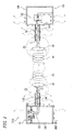
- Fig. 10 shows the system configuration of a measurement system corresponding to the resonance-type non-contact power supply system 10 in which the power-transmission-side metal shield 80 and the power-receiving-side metal shield 90 are not electrically connected with the case connector 12.
- Fig. 11 shows the system configuration of a measurement system corresponding to the resonance-type non-contact power supply system 110 in which the power-transmission-side metal shield 80 and the power-receiving-side metal shield 90 are electrically connected with the case connector 12.
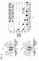
- Figs. 12(a) to 12(c) Measurement results regarding the relationship between the distance from the center of the primary resonance coil 35 and the secondary resonance coil 45 and the electric field strength are shown in Figs. 12(a) to 12(c) .
- the measured electric field is less than 27.5V/m that is a value in ICNIRP human body protection guidelines (referred to as, "guidelines", hereinafter) for the first time at a position P6. This is because the electric field that leaks from the space between the power-transmission-side metal shield 80 and the power-receiving-side metal shield 90 is large, and the danger zone becomes wide.
- the electric field that leaks to the outside is significantly reduced.
- the electric field at a position P2 (about 500mm away) almost becomes the same value as that in the guidelines, and the electric field at a position P3 (about 600mm away) becomes less than the value in the guidelines.
- the danger zone in which the electric field is larger than the value in the guidelines can be significantly reduced.
- the magnetic field occurs as electromagnetically coupled energy between the primary resonance coil 35 and the secondary resonance coil 45 not due to the potential difference between the power-transmission-side metal shield 80 and the power-receiving-side metal shield 90, and the leakage largely depends on the distance between the power-transmission-side metal shield 80 and the power-receiving-side metal shield 90. Therefore, between the distance between the power-transmission-side metal shield 80 and the power-receiving-side metal shield 90 is fixed, the change of the magnetic field is not observed obviously.
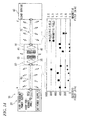
- Figs. 14 and 15 Results of measuring the electromagnetic field strength (electric field and radiated electromagnetic field) around the power-transmission-side and the power-receiving-side coaxial cables 60, 70 are shown in Figs. 14 and 15 .
- Fig. 14 shows the measurement result of the resonance-type non-contact power supply system 10 in which the power-transmission-side metal shield 80 and the power-receiving-side metal shield 90 are not electrically connected by the case connector 12.
- Fig. 15 shows the measurement result of the resonance-type non-contact power supply system 110 in which the power-transmission-side metal shield 80 and the power-receiving-side metal shield 90 are electrically connected by the case connector 12.
- the electric field at the power transmission side is measured to have values of 400-800V/m.
- the electric field at the power receiving side is measured to have values of about 200-400V/m.
- the magnetic field is measured to have values of about 0.2-0.5A/m.
- the measurement results shown in Fig. 15 indicates that both the electric field and the magnetic field have values of approximate 0.
- the resonance-type non-contact power supply system 110 including the case connecting part the radiated electromagnetic field can be significantly reduced.
- the transmission efficiency can be improved and the radiated electromagnetic field can be reduced in a simple and low cost way.
- the weight can be less than that when the whole system is shielded. Therefore, even if the power supply system is carried on a mobile body such as a vehicle, the increase of the energy consumption due to the weight increase can be suppressed.
- the danger zone can be significantly decreased, and measures against entries to the danger zone become easy. That is, devices such as human sensors can be significantly reduced, and operations can be performed simply.
- the primary resonance coil 35 and the secondary resonance coil 45 are loop power-supply type (indirect type) ones for which the primary coil 30 and the secondary coil 40 are used, but the primary resonance coil 35 and the secondary resonance coil 45 may be direct power-supply type ones.
- the transmission outputs may be changed according to the connection number, and the transmission outputs may be reduced when the connection number is below a given number.
- the present invention is useful in the field of resonance-type non-contact power supply systems.
Landscapes
- Engineering & Computer Science (AREA)
- Power Engineering (AREA)
- Computer Networks & Wireless Communication (AREA)
- Transportation (AREA)
- Mechanical Engineering (AREA)
- General Chemical & Material Sciences (AREA)
- Chemical Kinetics & Catalysis (AREA)
- Electrochemistry (AREA)
- Chemical & Material Sciences (AREA)
- Manufacturing & Machinery (AREA)
- Physics & Mathematics (AREA)
- Electromagnetism (AREA)
- Electric Propulsion And Braking For Vehicles (AREA)
- Charge And Discharge Circuits For Batteries Or The Like (AREA)
- Current-Collector Devices For Electrically Propelled Vehicles (AREA)
- Shielding Devices Or Components To Electric Or Magnetic Fields (AREA)
- Secondary Cells (AREA)
Abstract
Description
- The present invention relates to a resonance-type non-contact power supply system, and a power-receiving-side device and a power-transmission-side device which are used in the resonance-type non-contact power supply system.
- A technique in which electric power is supplied to a load device by a non-contact system is known. In recent years, the non-contact power supply system is practically used even as a power supply system for electric vehicles, various standards are established, and safety for common use is considered.
- There are various types of non-contact power supply system. A power supply system for electric vehicles is a resonance-type non-contact power supply system, which is shown in
Fig. 1(a) , which greatly attracts attentions and whose basic principle is developed and demonstrated by MIT (Massachusetts Institute of Technology) (for example, refer to a patent document 1). The resonance-type non-contact power supply system shown in the includes a resonance system of a high frequency power supply, resonance coils (primary and secondary resonance coils) and a load that transmits electric power non-contactly. Specifically, power-transmission-side (primary side) devices include a high frequency power supply, a primary coil, and a primary resonance coil. Power-receiving-side (secondary side) devices include a secondary resonance coil, a secondary coil and a load. The power-transmission-side devices and the power-receiving-side devices in the system have an advantage of being able to supply electric power to a place spaced several meters with a high transmission efficiency (sometimes around 50%) by being magnetically coupled (electromagnetically coupled) by resonance. - In the technique of MIT shown in
Fig. 1(a) , the resonance system is assumed to be configured with "a power supply part (the high frequency power supply and the primary coil), a resonance part (the primary resonance coil and the secondary resonance coil), and a load part (the secondary coil and the load)". However, additional components become necessary when the non-contact power supply system is mounted in an electronic device or an automobile power supply system. A system configuration example where the system ofFig. 1(a) is mounted in a real system is shown inFig. 1(b) . As shown in the figure, in the real system, a transmission path between the power supply and a primary resonance coil part and a transmission path between a secondary resonance coil part and the load are necessary. -
- Patent document 1: Japan Patent Publication No.
2009-501510 - Patent document 2: Japan Patent Publication No.
2010-40699 - Patent document 3: Japan Patent Publication No.
5-344602 - A resonance-type non-contact
power supply system 510 that is more specifically configured than inFig. 1(b) is shown inFig. 2 . As shown in the figure, when coaxial cables (a power-transmission-sidecoaxial cable 60 and a power-receiving-side coaxial cable 70) are used, there are the following problems. - (1) When a coaxial cable is used for the transmission path, an electric current flows through not only the inner side but also the outer side of a coaxial cable
outer conductor 64 of the primary coaxial cable (the power-transmission-side coaxial cable 60), and a radiated electromagnetic field occurs. - (2) Because part of the electromagnetic field from a
primary coil 30 is coupled with the coaxial cableouter conductor 64 and an induced current flows, a radiated electromagnetic field occurs. - (3) Because all of the electromagnetic field from a
secondary resonance coil 45 is not necessarily coupled with asecondary coil 40, part of the electromagnetic field is coupled with a coaxial cableouter conductor 74 of a power-receiving-sidecoaxial cable 70, and an induced current flows, a radiated electromagnetic field occurs. - An example in which the resonance-type non-contact
power supply system 510 is applied to a charging system for electric vehicles or the like is shown inFigs. 3(a) and 3(b) . Power-transmission-side (primary side) devises (20, 30 and 35) are arranged underground. When avehicle 1 including power-receiving-side (secondary side) devices (50, 40 and 45) is placed above the power-transmission-side devices, non-contact power transmission is enabled. Since it is necessary for the charging system for electric vehicles to transmit electric power in a short time, it is thought that large electric power transmission that exceeds, for example, 1kW is demanded. However, as shown inFig. 3(a) , when the large electric power transmission is performed, a radiated electromagnetic field more than a reference value (DA) of ICNIRP human body protection guidelines may occur between theprimary resonance coil 35 and thesecondary resonance coil 45, that is, between the vehicle and the road surface. When the radiated electromagnetic field leaks out in a wide area, a human body M1 and electronic devices may be adversely affected. Therefore, as shown inFig. 3(b) , in order that a danger zone where the electromagnetic field strength exceeds a reference value of ICNIRP human body protection guidelines may not be entered, measures to surround an area (the danger zone) where the transmission is performed with a shielding such as afence 2 are considered. However, if a child M2 or a small animal P2 such as a pet who cannot understand a rule enters the danger zone, an accident may happen. Furthermore, it is considered to construct a system which stops charging immediately when sensors which are arranged in several places and sense whether the danger zone is entered recognize an entry. However, it is difficult to decide criteria for an object that entered the danger zone when the number of the sensors increases. - The invention is made in view of these situations, and the object of the invention is to provide a technique to solve the above problems.
- According to an aspect of the invention, there is provided a power-transmission-side device used in a resonance-type non-contact power supply system, which transmits electric power by a non-contact resonance effect from a power-transmission-side resonance coil part connected to a high frequency power supply by a coaxial cable to a power-receiving-side resonance coil part, the power-transmission-side device including: a power-transmission-side shield part which is a good conductor and covers from outside to accommodate the power-transmission-side resonance coil part, and which is electrically connected to a housing of the high frequency power supply by an outer conductor of the coaxial cable, and a case connecting part which electrically connects the power-transmission-side shield part to a power-receiving-side shield part which is a good conductor and covers from outside to accommodate the power-receiving-side resonance coil part so that a positional deviation can be absorbed.
- Further, the case connecting part may be constructed to connect the power-transmission-side shield part and the power-receiving-side shield part when non-contact power supply is performed, and to be accommodated when the non-contact power supply is not performed.
- According to another aspect of the invention, there is provided a power-receiving-side device used in a resonance-type non-contact power supply system, which transmits electric power by a non-contact resonance effect from a power-transmission-side resonance coil part connected to a high frequency power supply to a power-receiving-side resonance coil part connected to a load device by a coaxial cable, the power-receiving-side device including: a power-receiving-side shield part which is a good conductor and covers from outside to accommodate the power-receiving-side resonance coil part, and which is electrically connected to a housing of the load device by an outer conductor of the coaxial cable, and a case connecting part which electrically connects the power-receiving-side shield part to a power-transmission-side shield part which is a good conductor and covers from outside to accommodate the power-transmission-side resonance coil part so that a positional deviation can be absorbed.
- Further, the case connecting part may be constructed to electrically connect the power-receiving-side shield part and the power-transmission-side shield part when non-contact power supply is performed, and to be accommodated when the non-contact power supply is not performed.
- Further, there is provided a resonance-type non-contact power supply system that transmits electric power by a non-contact resonance effect from a power-transmission-side resonance coil part, which is connected to a high frequency power supply by a first coaxial cable, to a power-receiving-side resonance coil part, which is connected to a load device by a second coaxial cable, the system including: a power-transmission-side shield part which is a good conductor and covers from outside to accommodate the power-transmission-side resonance coil part, and which is electrically connected to a housing of the high frequency power supply by an outer conductor of the first coaxial cable; a power-receiving-side shield part which is a good conductor and covers from outside to accommodate the power-receiving-side resonance coil part, and which is electrically connected to a housing of the load device by an outer conductor of the second coaxial cable, and a case connecting part which electrically connects the power-transmission-side shield part and the power-receiving-side shield part so that a positional deviation can be absorbed.
- The power-receiving-side shield part may be provided with the case connecting part which is constructed to electrically connect the power-receiving-side shield part and the power-transmission-side shield part when non-contact power supply is performed, and to be accommodatable when the non-contact power supply is not performed.
- The power-transmission-side shield part may be provided with the case connecting part which is constructed to electrically connect the power-receiving-side shield part and the power-transmission-side shield part when non-contact power supply is performed, and to be accommodatable when the non-contact power supply is not performed.
- According to the present invention, a technique to reduce the unnecessary radiated electromagnetic fields in the resonance-type non-contact power supply system can be provided.
-
- [
Fig. 1] Figs. 1(a) and 1(b) are figures to describe the principle of a resonance-type non-contact power supply system of the related art. - [
Fig. 2] Fig. 2 is a figure which schematically shows the construction of the resonance-type non-contact power supply system ofFig. 1 of the related art when the resonance-type non-contact power supply system is in a real system. - [
Fig. 3] Figs. 3(a) and 3(b) are figures which show an example in which the resonance-type non-contact power supply system of the related art is applied to a charging for electric vehicles or the like. - [
Fig.4] Fig. 4 is a schematic block diagram which shows the construction of a resonance-type non-contact power supply system including power-transmission-side and power-receiving-side metal shields according to an embodiment of the invention. - [
Fig.5] Fig. 5 is a schematic block diagram which shows the construction of a non-contact power supply system, in which power-transmission-side and power-receiving-side metal shields are connected, according to the embodiment of the invention. - [
Fig. 6] Fig. 6 is a figure which shows an example in which the resonance-type non-contact power supply system, in which the power-transmission-side and power-receiving-side metal shields are connectable, is applied to a charging system for electric vehicles or the like, according to the embodiment of the invention. - [
Fig. 7] Figs. 7(a) and 7(b) are figures which schematically show an example of the power-transmission-side and the power-receiving-side metal shields which are connected by a case connecting part, according to the embodiment of the invention. - [
Fig. 8] Figs. 8(a) and 8(b) are figures which schematically show an example of the power-transmission-side and the power-receiving-side metal shields which are connected by a case connecting part, according to the embodiment of the invention. - [
Fig. 9] Figs. 9(a) and 9(b) are figures which schematically show an example of the power-transmission-side and the power-receiving-side metal shields which are connected by a case connecting part, according to the embodiment of the invention. - [
Fig. 10] Fig. 10 is a figure which shows the construction of a system of measuring the electromagnetic field strength in the related-art resonance-type non-contact power supply system that is a comparative example, according to the embodiment of the invention. - [
Fig. 11] Fig. 11 is a figure which shows the construction of a system of measuring the electromagnetic field strength in the resonance-type non-contact power supply system of the embodiment of the invention, according to the embodiment of the invention. - [
Fig. 12] Figs. 12(a) to 12(c) are figures which show measurement data that show the relationship between distance from a resonance coil center and electric field strength in the resonance-type non-contact power supply system, according to the embodiment of the invention, in whichFig. 12(a) is a figure which shows measurement points from the resonance coil center when the metal cases do not contact each other,Fig. 12(b) is a figure which shows measurement points from the resonance coil center when the metal cases contact each other, andFig. 12(c) shows the measurement data which show the relationship between the distance from the resonance coil center and the electric field strength. - [
Fig. 13] Figs. 13(a) to 13(c) are figures which show measurement data that show the relationship between distance from a resonance coil center and magnetic field strength in the resonance-type non-contact power supply system, according to the embodiment of the invention, in whichFig. 13(a) is a figure which shows measurement points from the resonance coil center when the metal cases do not contact each other,Fig. 13(b) is a which shows measurement points from the resonance coil center when the metal cases contact each other, andFig. 13(c) shows the measurement data which show the relationship between the distance from the resonance coil center and the electric field strength. - [
Fig. 14] Fig. 14 is a figure which shows measurement data of the electromagnetic field strength near the coaxial cables in the related-art resonance-type non-contact power supply system that is the comparative example, according to the embodiment of the invention. - [
Fig. 15] Fig. 15 is a figure which shows measurement data of the electromagnetic field strength near the coaxial cables in the resonance-type non-contact power supply system, according to the embodiment of the invention. - Below, modes for carrying out the invention (hereinafter referred to as "embodiments") are explained with reference to the figures. An outline of the present embodiment is as follows. In the resonance-type non-contact power supply system of the present embodiment, areas around a primary and a secondary resonance coil parts are covered with metal cases (metal shields), and the metal cases are electrically connected with the outer conductors of coaxial line cables. When the resonance-type non-contact power supply system is provided to a charging system of electric vehicles or the like, areas where the electromagnetic field strength exceeds the reference value of the guidelines at the time of charging is reduced, and safe zones are secured with few sensors as possible. For this purpose, at the time of power supply (charging), the power-transmission-side and the power-receiving-side metal cases are electrically connected, and the potential difference between those two metal cases becomes zero. Furthermore, to secure the arrangement flexibility of a vehicle at the time of charging, a structure to absorb a positional deviation when the metal cases are electrically connected is adopted.
- First, a model of a resonance-type non-contact
power supply system 10 which is applied to an electric vehicle charging system is described with reference toFig. 4 . The resonance-type non-contactpower supply system 10 is different from the resonance-type non-contactpower supply system 510 ofFig. 2 in that a power-transmission-side metal shield (metal case) 80 and a power-receiving-side metal shield (metal case) 90 are provided. Other components are the same, and some of the same components are given the same symbols. Because the technique disclosed in thereference document 1 can be used to explain the electric power transmission principle of the resonance-type non-contact power supply system, the detailed description is omitted here. - The resonance-type non-contact
power supply system 10 includes a highfrequency power supply 20, aprimary coil 30 and aprimary resonance coil 35 as power-transmission-side (primary side) devices. When the resonance-type non-contactpower supply system 10 is mounted in electric vehicle charging system, the power-transmission-side (primary side) devices are embedded under a road surface. Theprimary coil 30 is connected to the highfrequency power supply 20 by using a power-transmission-sidecoaxial cable 60. More specifically, the highfrequency power supply 20 includes anoscillation source 22 inside apower supply housing 24, and is connected to theprimary coil 30 by the power-transmission-sidecoaxial cable 60. Thepower supply housing 24 is grounded to a ground GND. To ground thepower supply housing 24, an exclusive ground line may be used, or FIG (Frame Ground) lines of AC cables or the like may be used. It is described that thesystem 10 includes the highfrequency power supply 20, but the system may be constructed without the highfrequency power supply 20. In this case, the system, 10 may be so constructed that a suitable high frequency electric power supply outside thesystem 10 is connectable and electric power from the high frequency power supply may be received. - The resonance-type non-contact
power supply system 10 includes the power-transmission-side metal shield 80 to cover the area around theprimary coil 30 and theprimary resonance coil 35. The power-transmission-side metal shield 80, for example, has an opening towards the power receiving side (secondary side; right side in the figure), has a case-like (tube-like) shape, and is made of metal of a good conductor such as steel or copper. That is, ashield side 82 of the power-transmission-side metal shield 80 completely covers the area around theprimary coil 30 and theprimary resonance coil 35 except the opening. A cylindrical shape, a prismatic shape or the like can be suitably adopted as the shape of the power-transmission-side metal shield 80 as long as the function as a shield case can be realized. The material of the power-transmission-side metal shield 80 may be suitably chosen as long as the power-transmission-side metal shield 80 is a conductor. - A
shield bottom 84 of the power-transmission-side metal shield 80 is provided with a transmission opening for the transmission path between the highfrequency power supply 20 and theprimary coil 30, and the power-transmission-sidecoaxial cable 60 is connected to the transmission opening. More specifically, one end (at the right side in the figure) of a coaxial cableouter conductor 64 of the power-transmission-sidecoaxial cable 60 is connected to theshield bottom 84 of the power-transmission-side metal shield 80. The other end (at the left side in the figure) of the coaxial cableouter conductor 64 is connected to thepower supply housing 24 of the highfrequency power supply 20. A coaxial cableinner conductor 62 directly connects theoscillation source 22 of the highfrequency power supply 20 and theprimary coil 30. - On the other hand, the resonance-type non-contact
power supply system 10 includes aload device 50, asecondary coil 40 and asecondary resonance coil 45 as power-receiving-side (secondary side) devices. When the resonance-type non-contactpower supply system 10 is mounted in an electric vehicle charging system, the power-receiving-side (secondary side) devices are carried in a vehicle. Aload 52 such as batteries is provided inside aload housing 54 of theload device 50. Theload device 50 and thesecondary coil 40 are connected by a power-receiving-sidecoaxial cable 70. It is described that thesystem 10 includes theload device 50, but the system may be constructed without theload device 50. In this case, thesystem 10 may be so constructed that a suitable load device outside thesystem 10 is connectable and electric power can be supplied to the load device. - The resonance-type non-contact
power supply system 10 includes a power-receiving-side metal shield 90, like the power-transmission-side metal shield 80 at the power transmission side, to cover thesecondary coil 40 system, thesecondary resonance coil 45. More specifically, the power-receiving-side metal shield 90, for example, has an opening towards the power transmission side (primary side; left side in the figure), has a case-like (tube-like) shape, and is made of metal of a good conductor such as steel or copper. That is, ashield side 92 of the power-receiving-side metal shield 90 completely covers the area around thesecondary coil 40 and thesecondary resonance coil 45 except the opening. A cylindrical shape, a prismatic shape or the like can be suitably adopted as the shape of the power-receiving-side metal shield 90 as long as the function as a shield case can be realized. The material of the power-receiving-side metal shield 90 may be suitably chosen as long as the power-receiving-side metal shield 90 is a conductor. - A
shield bottom 94 of the power-receiving-side metal shield 90 is provided with a transmission opening for the transmission path between theload device 50 and thesecondary coil 40, and the power-receiving-sidecoaxial cable 70 is connected to the transmission opening. More specifically, one end (at the left side in the figure) of a coaxial cableouter conductor 74 of the power-receiving-sidecoaxial cable 70 is connected to theshield bottom 94 of the power-receiving-side metal shield 90. The other end (at the right side in the figure) of the coaxial cableouter conductor 74 is connected to theload housing 54 of theload device 50. A coaxial cableinner conductor 72 is directly connected to theload 52 in theload housing 54. - In the resonance-type non-contact
power supply system 10 having the above-mentioned construction, while the transmission path from theoscillation source 22 to theprimary coil 30 and the transmission path from theload 52 to thesecondary coil 40 are formed, theoscillation source 22 oscillates at a high frequency of, for example, several MHz to several 10MHz, and the oscillation output is supplied to theprimary coil 30. Theprimary resonance coil 35 amplifies the electric power of theprimary coil 30, and produces an electromagnetic field towards thesecondary resonance coil 45. Thesecondary resonance coil 45 is coupled with the electromagnetic field that is produced by theprimary resonance coil 35, and produces an induced current to thesecondary coil 40. As a result, the electric power is supplied to theload 52. - At this time, because, at the power transmission side of the above described related-art resonance-type non-contact
power supply system 510, an induced current flows to the ground GND through not only the inner side but also the outer side of the coaxial cableouter conductor 64 of the power-transmission-sidecoaxial cable 60, a radiated electromagnetic field occurs around the power-transmission-sidecoaxial cable 60. Because, at the power receiving side of the resonance-type non-contactpower supply system 510, all of the electromagnetic field from thesecondary resonance coil 45 is not coupled with thesecondary coil 40, part of the electromagnetic field is coupled with the coaxial cableouter conductor 74, and an induced current, which becomes a transmission loss, occurs, a radiated electromagnetic field occurs around the power-receiving-sidecoaxial cable 70 as a result. - However, in the present collection of transmission energy inside the power-transmission-side
coaxial cable 60 and the power-receiving-sidecoaxial cable 70 is improved. That is, because the area around the power-transmission-side (primary side) resonance part (theprimary coil 30 and the (primary resonance coil 35) is covered by the power-transmission-side metal shield 80, and the power-transmission-side metal shield 80 and the coaxial cableouter conductor 64 of the power-transmission-sidecoaxial cable 60 are electrically connected, the electric current which flows out to the outside of the coaxial cableouter conductor 64 at the power transmission side can be collected inwards. Similarly, because the area around the power-receiving-side (primary side) resonance part (thesecondary coil 40 and the secondary resonance coil 45) is covered by the power-receiving-side metal shield 90, and the power-receiving-side metal shield 90 and the coaxial cableouter conductor 74 of the power-receiving-sidecoaxial cable 70 are electrically connected, the electric current which flows out to the outside of the coaxial cableouter conductor 74 at the power receiving side can be collected inwards. As a result, the transmission efficiency can be improved, and the radiated electromagnetic field can be reduced. - Although the reduction of the radiated electromagnetic field can be realized by the construction shown in
Fig. 4 , because large electric power transmission is assumed in the electric vehicle charging system as described above, further reduction is necessary. In the above construction, a potential difference may be produced between the power-transmission-side metal shield 80 and the power-receiving-side metal shield 90. When a potential difference occurs, an electric field occurs. Further, an electromagnetic field may leak from a space S1 between the power-transmission-side metal shield 80 and the power-receiving-side metal shield 90 to the outside. Although the electric field can be greatly reduced as compared to before, it is desirable to bring the electric field close to zero. - Thus, as shown in
Fig. 5 , by providing acase connector 12 to electrically connect the power-transmission-side metal shield 80 and the power-receiving-side metal shield 90, the potential difference between the power-transmission-side metal shield 80 and the power-receiving-side metal shield 90 disappears, and the electric field that occurs due to the potential difference can be prevented from occurring. - Then, with reference to a resonance-type non-contact
power supply system 110 ofFig. 6 , a detailed embodiment which is applied in an electric vehicle charging system is described. The construction of the resonance-type non-contactpower supply system 110 is basically the same as that of the above- mentioned resonance-type non-contactpower supply system 10. - As shown in the figure, the power-transmission-side devices system, the high
frequency power supply 20 and theprimary resonance coil 35 are embedded under a road surface. Theprimary resonance coil 35 is arranged near the road surface. The area around theprimary resonance coil 35 is covered by the power-transmission-side metal shield 80 as shown inFigs. 4 and5 . The upper side (the side of the vehicle 1) of the power-transmission-side metal shield 80 in the figure system, the opening where there is no shield material. However, the opening is covered with acover body 88 of materials such as resin. It is preferable that the material of thecover body 88 does not affect the coupling of electric fields. - A power-transmission-side case connecting part 14 is provided near the upper distal end of the
shield side 82 of the power-transmission-side metal shield 80 as thecase connector 12. Although specific examples of the power-transmission-side case connecting part 14 are illustrated inFigs. 7(a) to 9(b) , the power-transmission-side case connecting part 14 is a conductor, and has a shape that can be transformed. More specifically, the power-transmission-side case connecting part 14 is a board-like body, is maintained as a usually desired shape when no charging is performed, and can be transformed when in contact with the power-receiving-side metal shield 90 of thevehicle 1 to secure the connection. For example, the material of the power-transmission-side case connecting part 14 may be conductive rubber or resin material whose surface is processed to have conductivity. The power-transmission-side case connecting part 14 is usually arranged horizontally on the road surface, and is vertically driven by a motor or the like at the time of charging. It is preferable that there are a plurality of power-transmission-side case connecting parts 14 in view of a parking positional tolerance of thevehicle 1 and the variety of the shape of the power-receiving-side metal shield 90. - On the other hand, the power-receiving-side devices including the
load device 50 which is a battery device and thesecondary resonance coil 45 are carried in thevehicle 1. Thesecondary resonance coil 45 is arranged near the floor of thevehicle 1. The area around thesecondary resonance coil 45 is covered by the power-receiving-side metal shield 90 as shown inFigs. 4 and5 . The lower side (the side of the road surface) of the power-receiving-side metal shield 90 in the figure becomes the opening where there is no shield material. However, the opening is covered with acover body 98 of material such as resin. It is preferable that the material of thecover body 98 does not affect the coupling of electric fields. - A power-receiving-side case connecting part 13 is provided near the lower distal end of the
shield side 92 of the power-receiving-side metal shield 90 as thecase connector 12. Although specific examples of the power-receiving-side case connecting part 13 are illustrated inFigs. 7(a) to 9(b) , the power-receiving-side case connecting part 13 is a conductor, and has a shape that can be transformed. More specifically, the power-receiving-side case connecting part 13 is a board-like body, is maintained as a usually desired shape when no charging is performed, and can be transformed when in contact with the power-transmission-side metal shield 80 at the charging position to secure the connection. For example, the material of the power-receiving-side case connecting part 13 may be conductive rubber or resin material whose surface is processed to have conductivity. The power-receiving-side case connecting part 13 is usually arranged horizontally on the floor surface (lower outer surface) of thevehicle 1, and is vertically driven by a motor or the like at the time of charging. It is preferable that there are a plurality of power-receiving-side case connecting parts 13, like the power-transmission-side case case connecting parts 14, in view of a parking positional tolerance of thevehicle 1 and the variety of the shape of the power-transmission-side metal shield 80. - Although it is described that the resonance-type non-contact
power supply system 110 includes both the power-receiving-side case connecting part 13 and the power-transmission-side case connecting part 14, it is also possible that the resonance-type non-contactpower supply system 110 includes either of the power-receiving-side case connecting part 13 and the power-transmission-side case connecting part 14. - when the
vehicle 1 is located on the power-transmission-side devices including theprimary resonance coil 35 for the purpose of charging, theprimary resonance coil 35 and thesecondary resonance coil 45 face each other. Prior to the transmission for charging, the power-receiving-side case connecting part 13 and the power-transmission-side case connecting part 14, as thecase connector 12, are driven so that their positions are controlled. As a result, as shown inFig. 6 , the power-receiving-side case connecting part 13 is connected to the power-receiving-side metal shield 90, and the power-transmission-side case connecting part 14 is connected to the power-transmission-side metal shield 80. At this time, the power-receiving-side case connecting part 13 and the power-transmission-side case connecting part 14 are formed to be longer than the distance between thevehicle 1 and the road surface, and by flexing the power-receiving-side case connecting part 13 and the power-transmission-side case connecting part 14 so that they are pressed at the time of connecting, an electrical connection is well maintained. Generally, it is thought that, prior to the charging, a user authentication process is performed by communication with a device which manages thevehicle 1 and the power-transmission-side devices. By incorporating a determination whether or not the connection of thecase connector 12 is secured in one process of the authentication process, and controlling so that a charging process will not start when the connection is not secured, a safe charging system can be implemented. - Then, construction variations of the power-receiving-side case case connecting part 13 and the power-transmission-side case connecting part 14 are described with reference to
Figs. 7(a) to 9(b) . -
Figs. 7(a) and 7(b) show that the power-receiving-side metal shield 90 of thevehicle 1 is provided with the power-receiving-side case connecting part 13 (13a, 13b), and the power-transmission-side metal shield 80 is not provided with the case connector 12 (the power-transmission-side case connecting part 14). - The upper end, namely, the end at the road surface side, of the
shield side 82 of the power-transmission-side metal shield 80 is provided with a plane-formed shield front part 86 (86a, 86b), which extends outwards a given length beyond the opening end and is formed to face the floor of thevehicles 1. The extension length is set by assuming an allowable range in the parking position of thevehicle 1 may deviate. - When charging is not performed, as shown in
Fig. 7(a) , and the power-receiving-side case connecting part 13 (13a, 13b) is maintained horizontally. When the charging is performed, the power-receiving-side case connecting part 13 is driven to become vertical, and as shown inFig. 7(b) , the power-receiving-side casecase connecting part 13a at the right side in the figure is flexed and connected to the shieldfront part 86a at the right side in the figure. On the other hand, because even if the power-receiving-sidecase connecting part 13b at the left side in the figure is controlled to become vertical, the shield front part 86 is not located right below, the power-receiving-sidecase connecting part 13b is accommodated horizontally. Because the shield front part 86 is a conductor, whether the shield front part 86 is right below can be determined by a known sensing technology. - Contrary to
Figs. 7(a) and 7(b) ,Figs. 8(a) and 8(b) show that only the power-transmission-side metal shield 80 is provided with the case connector 12 (power-transmission-sidecase connecting parts - The lower end, namely, the end at the floor side, of the
shield side 92 of the power-receiving-side metal shield 90 is provided with a plane-formed shield front part 96 (96a, 96b), which extends outwards a given length beyond the opening end and is formed to face the road surface. The extension length is set by assuming an allowable range in which the parking position of thevehicle 1 may deviate. - When charging is not performed, as shown in
Fig. 8(a) , the power-transmission-side case connecting part 14 (14a, 14b) is maintained horizontally (parallel to the floor). When the charging is performed, the power-transmission-side case connecting part 14 is driven to become vertical, and as shown inFig. 8(b) , the power-transmission-sidecase connecting part 14a at the right side in the figure is flexed and connected to the shieldfront part 96a at the right side in the figure. On the other hand, because even if the power-transmission-sidecase connecting part 14b at the left side in the figure is controlled to become vertical, the shieldfront part 86b is not located right above, the power-transmission-sidecase connecting part 14b is accommodated horizontally. Because the shield front part 96 is a conductor, whether the shield front part 96 is right above can be determined by a known sensing technology. -
Figs. 9(a) and 9(b) show that both the power-transmission-side metal shield 80 and the power-receiving-side metal shield 90 are provided with thecase connector 12. The power-transmission-side metal shield 80 includes the shield front part 86 and includes the power-transmission-side case connecting part 14. Similarly, the power-receiving-side metal shield 90 includes the shield front part 96 and includes the power-receiving-side case connecting part 13. When charging is performed, the power-receiving-side case connecting part 13 and the power-transmission-side case case connecting part 14 are driven to become vertical so that the power-transmission-side metal shield 80 and the power-receiving-side metal shield 90 are electrically connected. The power-transmission-sidecase connecting part 14a at the right side and the power-receiving-sidecase connecting part 13b at the left side in the figure are vertically flexed and connected. On the other hand, the power-transmission-side casecase connecting part 14b at the left side and the power-receiving-side casecase connecting part 13a at the right side in the figure as shown with broken lines, which are not used for connection, are arranged horizontally - Sensing results of the shield front parts 86, 96 as mentioned above can be used to determine whether any one of the
case connectors 12 is driven vertically or arranged horizontally It also can be assumed that both the power-receiving-side case connecting part 13 and the power-transmission-side case connecting part 14 are used for connection. In such a case, if thecase connector 12 which is moved with precedence is set beforehand, a smooth operation is enabled. - Next, with reference to
Figs. 10 to 15 , the radiated electromagnetic fields in the resonance-type non-contactpower supply system 110 in which the power-transmission-side metal shield 80 (power-transmission-side case) and the power-receiving-side metal shield 90 (power-receiving-side case) are electrically connected with thecase connector 12 and the resonance-type non-contactpower supply system 10 in which the power-transmission-side metal shield 80 and the power-receiving-side metal shield 90 are not electrically connected with thecase connector 12 are measured. Measurement results are described.Fig. 10 shows the system configuration of a measurement system corresponding to the resonance-type non-contactpower supply system 10 in which the power-transmission-side metal shield 80 and the power-receiving-side metal shield 90 are not electrically connected with thecase connector 12.Fig. 11 shows the system configuration of a measurement system corresponding to the resonance-type non-contactpower supply system 110 in which the power-transmission-side metal shield 80 and the power-receiving-side metal shield 90 are electrically connected with thecase connector 12. - Summaries of the system configurations of the measurement systems of
Figs. 10 and11 are as follows. - (1) The high frequency power supply 20:
- the frequency is 13.56MHZ (+-1MHz), and the output power is 3kW.
- (2) The coaxial cable (the power-transmission-side coaxial cable 60):
- a coaxial cable (3m) is used as a high frequency electric power transmission line and connects the high
frequency power supply 20 and the loop coil (the primary coil 30), and there are 5 electromagnetic field measurement spots (spaced 50cm).
- a coaxial cable (3m) is used as a high frequency electric power transmission line and connects the high
- (3) The coaxial cable (the power-receiving-side coaxial cable 70):
- a coaxial cable (2m) is used as a high frequency electric power transmission line and connects the power-receiving-side loop coil (the secondary coil 40) and the attenuator (load).
- (4) The loop coils (30, 40): the loop coils 30, 40 are made of copper, have a diameter of 150mm, and are made of copper wires of 5mm in diameter, and the power-transmission-side construction is the same as the power-receiving-side construction.
- (5) The resonance coils (35, 45): the resonance coils made of copper, have a diameter of 300mm, an inside diameter of 185mm and a pitch of 5mm and are spiral coils made of copper wires of 5mm in diameter, the power-transmission-side construction is the same as the power-receiving-side construction, and the distance between the coils is 200mm.
- (6) The metal cases (the power-transmission-side and power-receiving-side metal shields 80, 90): the metal cases are connected to the coaxial cable
outer conductors coaxial cables - (7) The load device 50:
- the power-receiving-side high frequency electric power is attenuated a given quantity by the attenuator, and a signal level is measured with a spectrum analyzer.
- (8) The
case connector 12 <Fig. 11 ; only for the present embodiment>:- the power-transmission-side and the power-receiving-side metal shields 80, 90 are connected by the
case connector 12, and the potential difference between the two metal shields becomes zero.
- the power-transmission-side and the power-receiving-side metal shields 80, 90 are connected by the
- Measurement results regarding the relationship between the distance from the center of the
primary resonance coil 35 and thesecondary resonance coil 45 and the electric field strength are shown inFigs. 12(a) to 12(c) . As shown in the figure, when the power-transmission-side metal shield 80 and the power-receiving-side metal shield 90 are not connected by thecase connector 12, the measured electric field is less than 27.5V/m that is a value in ICNIRP human body protection guidelines (referred to as, "guidelines", hereinafter) for the first time at a position P6. This is because the electric field that leaks from the space between the power-transmission-side metal shield 80 and the power-receiving-side metal shield 90 is large, and the danger zone becomes wide. On the other hand, when the power-transmission-side metal shield 80 and the power-receiving-side metal shield 90 are connected by thecase connector 12 and the potential difference becomes zero, the electric field that leaks to the outside is significantly reduced. The electric field at a position P2 (about 500mm away) almost becomes the same value as that in the guidelines, and the electric field at a position P3 (about 600mm away) becomes less than the value in the guidelines. Thus, the danger zone in which the electric field is larger than the value in the guidelines can be significantly reduced. - Measurement results regarding the relationship between the distance from the center of the
primary resonance coil 35 and thesecondary resonance coil 45 and the magnetic field strength are shown inFigs. 13(a) to 13(c) . From the measurement results shown in the figure, it can be seen that the magnetic field strength when the power-transmission-side metal shield 80 and the power-receiving-side metal shield 90 are connected is not significantly different from, but slightly less than that when the power-transmission-side metal shield 80 and the power-receiving-side metal shield 90 are not connected. This is because the magnetic field occurs as electromagnetically coupled energy between theprimary resonance coil 35 and thesecondary resonance coil 45 not due to the potential difference between the power-transmission-side metal shield 80 and the power-receiving-side metal shield 90, and the leakage largely depends on the distance between the power-transmission-side metal shield 80 and the power-receiving-side metal shield 90. Therefore, between the distance between the power-transmission-side metal shield 80 and the power-receiving-side metal shield 90 is fixed, the change of the magnetic field is not observed obviously. - Results of measuring the electromagnetic field strength (electric field and radiated electromagnetic field) around the power-transmission-side and the power-receiving-side
coaxial cables Figs. 14 and15 .Fig. 14 shows the measurement result of the resonance-type non-contactpower supply system 10 in which the power-transmission-side metal shield 80 and the power-receiving-side metal shield 90 are not electrically connected by thecase connector 12.Fig. 15 shows the measurement result of the resonance-type non-contactpower supply system 110 in which the power-transmission-side metal shield 80 and the power-receiving-side metal shield 90 are electrically connected by thecase connector 12. - An outline of the measurement conditions is as follows.
- * Electromagnetic field sensors are installed at measurement points. The vertical distance from the measurement point to the electromagnetic field sensor surface is 50mm.
- * Electric power of a frequency of 13.56MHz and 3KW is output from the high
frequency power supply 20, and the maximum electric field values and the maximum magnetic field values measured by the electromagnetic field sensors are acquired. - First, as shown in
Fig. 14 , in the resonance-type non-contactpower supply system 10 which does not have thecase connector 12, the electric field at the power transmission side is measured to have values of 400-800V/m. The electric field at the power receiving side is measured to have values of about 200-400V/m. The magnetic field is measured to have values of about 0.2-0.5A/m. - On the other hand, for the resonance-type non-contact
power supply system 110 including thecase connector 12, the measurement results shown inFig. 15 indicates that both the electric field and the magnetic field have values of approximate 0. Thus, by adopting the resonance-type non-contactpower supply system 110 including the case connecting part, the radiated electromagnetic field can be significantly reduced. - According to the present embodiment, the transmission efficiency can be improved and the radiated electromagnetic field can be reduced in a simple and low cost way. By placing the metal cases only around the resonance coil parts, the weight can be less than that when the whole system is shielded. Thereby, even if the power supply system is carried on a mobile body such as a vehicle, the increase of the energy consumption due to the weight increase can be suppressed. Furthermore, when charging is performed, the danger zone can be significantly decreased, and measures against entries to the danger zone become easy. That is, devices such as human sensors can be significantly reduced, and operations can be performed simply.
- The present invention is described based on the embodiments as above. The above embodiments are illustrative and it is understood by those skilled in the art that it is possible to make various modifications to those components and their combination and that these modifications are also in the scope of the invention. For example, the
primary resonance coil 35 and thesecondary resonance coil 45 are loop power-supply type (indirect type) ones for which theprimary coil 30 and thesecondary coil 40 are used, but theprimary resonance coil 35 and thesecondary resonance coil 45 may be direct power-supply type ones. Besides, among the provided case connector 12 (the power-receiving-side case connecting part 13 and the power-transmission-side case connecting part 14), the transmission outputs may be changed according to the connection number, and the transmission outputs may be reduced when the connection number is below a given number. - Although the invention is described in detail with reference to specific embodiments, it is apparent that various modifications and amendments may be made by those skilled in the art without departing from the spirit and scope of the invention.
- This application is based on the Japanese patent application (patent application
2011-96362) filed on April 22, 2011 - The present invention is useful in the field of resonance-type non-contact power supply systems.
-
- 10, 110, 510
- resonance-type non-contact power supply system
- 20
- high frequency power supply
- 22
- oscillation source
- 24
- power supply housing
- 30
- primary coil
- 35
- primary resonance coil
- 40
- secondary coil
- 45
- secondary resonance coil
- 50
- load device
- 52
- load
- 54
- load housing
- 60
- power-transmission-side coaxial cable
- 62, 72
- coaxial cable inner conductor
- 64, 74
- coaxial cable outer conductor
- 66
- coaxial male connector
- 88, 98
- cover body
- 70
- power-receiving-side coaxial cable
- 80
- power-transmission-side metal shield
- 82, 92
- shield side
- 84, 94
- shield bottom
- 86, 96
- shield front part
- 90
- power-receiving-side metal shield
Claims (7)
- A power-transmission-side device used in a resonance-type non-contact power supply system, which transmits electric power by a non-contact resonance effect from a power-transmission-side resonance coil part connected to a high frequency power supply by a coaxial cable to a power-receiving-side resonance coil part, the power-transmission-side device comprising:a power-transmission-side shield part which is a good conductor and covers from outside to accommodate the power-transmission-side resonance coil part, and which is electrically connected to a housing of the high frequency power supply by an outer conductor of the coaxial cable, anda case connecting part which electrically connects the power-transmission-side shield part to a power-receiving-side shield part which is a good conductor and covers from outside to accommodate the power-receiving-side resonance coil part so that a positional deviation can be absorbed.
- The power-transmission-side device according to claim 1, wherein the case connecting part is constructed to connect the power-transmission-side shield part and the power-receiving-side shield part when non-contact power supply is performed, and to be accommodated when the non-contact power supply is not performed.
- A power-receiving-side device used in a resonance-type non-contact power supply system, which transmits electric power by a non-contact resonance effect from a power-transmission-side resonance coil part connected to a high frequency power supply to a power-receiving-side resonance coil part connected to a load device by a coaxial cable, the power-receiving-side device comprising:a power-receiving-side shield part which is a good conductor and covers from outside to accommodated the power-receiving-side resonance coil part, and which is electrically connected to a housing of the load device by an outer conductor of the coaxial cable, anda case connecting part which electrically connects the power-receiving-side shield part to a power-transmission-side shield part which is a good conductor and covers from outside to accommodate the power-transmission-side resonance coil part so that a positional deviation can be absorbed.
- The power-receiving-side device according to claim 3, wherein the case connecting part is constructed to electrically connect the power-receiving-side shield part and the power-transmission-side shield part when non-contact power supply is performed, and to be accommodated when the non-contact power supply is not performed.
- A resonance-type non-contact power supply system that transmits electric power by a non-contact resonance effect from a power-transmission-side resonance coil part, which is connected to a high frequency power supply by a first coaxial cable, to a power-receiving-side resonance coil part, which is connected to a load device by a second coaxial cable, the system comprising:a power-transmission-side shield part which is a good conductor and covers from outside to accommodate the power-transmission-side resonance coil part, and which is electrically connected to a housing of the high frequency power supply by an outer conductor of the first coaxial cable;a power-receiving-side shield part which is a good conductor and covers from outside to accommodate the power-receiving-side resonance coil part, and which is electrically connected to a housing of the load device by an outer conductor of the second coaxial cable, anda case connecting part which electrically connects the power-transmission-side shield part and the power-receiving-side shield part so that a positional deviation can be absorbed.
- The resonance-type non-contact power supply system according to claim 5, wherein the power-receiving-side shield part is provided with the case connecting part which is constructed to electrically connect the power-receiving-side shield part and the power-transmission-side shield part when non-contact power supply is performed, and to be accommodatable when the non-contact power supply is not performed.
- The resonance-type non-contact power supply system according to claim 5 or 6, wherein the power-transmission-side shield part is provided with the case connecting part which is constructed to electrically connect the power-receiving-side shield part and the power-transmission-side shield part when non-contact power supply is performed, and to be accommodatable when the non-contact power supply is not performed.
Applications Claiming Priority (2)
| Application Number | Priority Date | Filing Date | Title |
|---|---|---|---|
| JP2011096362A JP5740200B2 (en) | 2011-04-22 | 2011-04-22 | Resonant non-contact power feeding system, power receiving side device, and power transmitting side device |
| PCT/JP2012/060797 WO2012144640A1 (en) | 2011-04-22 | 2012-04-20 | Resonance-type non-contact power supply system, power-receiving-side device, and power-transmission-side device |
Publications (3)
| Publication Number | Publication Date |
|---|---|
| EP2701284A1 true EP2701284A1 (en) | 2014-02-26 |
| EP2701284A4 EP2701284A4 (en) | 2015-09-02 |
| EP2701284B1 EP2701284B1 (en) | 2018-01-10 |
Family
ID=47041736
Family Applications (1)
| Application Number | Title | Priority Date | Filing Date |
|---|---|---|---|
| EP12774391.2A Not-in-force EP2701284B1 (en) | 2011-04-22 | 2012-04-20 | Resonance-type non-contact power supply system, power-receiving-side device, and power-transmission-side device |
Country Status (6)
| Country | Link |
|---|---|
| US (1) | US9299492B2 (en) |
| EP (1) | EP2701284B1 (en) |
| JP (1) | JP5740200B2 (en) |
| KR (1) | KR101469407B1 (en) |
| CN (1) | CN103493335A (en) |
| WO (1) | WO2012144640A1 (en) |
Cited By (1)
| Publication number | Priority date | Publication date | Assignee | Title |
|---|---|---|---|---|
| WO2018019876A1 (en) * | 2016-07-27 | 2018-02-01 | Stephan Eder | Coil assembly |
Families Citing this family (22)
| Publication number | Priority date | Publication date | Assignee | Title |
|---|---|---|---|---|
| KR20140091604A (en) * | 2011-12-13 | 2014-07-21 | 야자키 소교 가부시키가이샤 | Structute for fixing electrical connection section, connector, and method for connecting connector |
| JP5718830B2 (en) * | 2012-01-16 | 2015-05-13 | トヨタ自動車株式会社 | vehicle |
| GB2503484A (en) * | 2012-06-27 | 2014-01-01 | Bombardier Transp Gmbh | Inductive vehicle charging station and method with lateral electromagnetic shielding |
| JP6124085B2 (en) * | 2012-07-05 | 2017-05-10 | パナソニックIpマネジメント株式会社 | Wireless power transmission device, wireless power transmission device and power reception device |
| JP5958217B2 (en) * | 2012-09-14 | 2016-07-27 | 株式会社デンソー | Wireless power supply system |
| JP5688549B2 (en) | 2013-04-10 | 2015-03-25 | パナソニック インテレクチュアル プロパティ コーポレーション オブアメリカPanasonic Intellectual Property Corporation of America | Coil module and electronic device |
| EP2808196A1 (en) * | 2013-05-29 | 2014-12-03 | Brusa Elektronik AG | Transformer element |
| JP2014241673A (en) * | 2013-06-11 | 2014-12-25 | 株式会社東芝 | Electromagnetic wave leakage prevention device |
| CN105431324B (en) | 2013-08-05 | 2017-08-18 | 株式会社Ihi | Screening arrangement and contactless power supply system |
| WO2015025438A1 (en) | 2013-08-23 | 2015-02-26 | 三菱電機エンジニアリング株式会社 | Resonant power transmission device and resonant power multiplexed transmission system |
| WO2015037046A1 (en) * | 2013-09-10 | 2015-03-19 | 中国電力株式会社 | Contactless power feeding system, and contactless power feeding method |
| CN105594096B (en) | 2013-09-27 | 2018-04-06 | 日产自动车株式会社 | Non-contact power supply system |
| JP2015186426A (en) * | 2014-03-26 | 2015-10-22 | 株式会社エクォス・リサーチ | Power reception system |
| CN103997134B (en) * | 2014-05-22 | 2016-01-13 | 中国矿业大学 | A radiation extinguishing wireless power transmission power supply device |
| CN104057842B (en) * | 2014-06-17 | 2017-01-11 | 西南交通大学 | Coaxial cable power supply system of electrified railway |
| JP6497643B2 (en) * | 2014-07-10 | 2019-04-10 | 清水建設株式会社 | Floor panel |
| JP6430304B2 (en) * | 2015-03-18 | 2018-11-28 | 株式会社ベルニクス | Non-contact power feeding device |
| WO2018016023A1 (en) * | 2016-07-20 | 2018-01-25 | 株式会社 ベルニクス | Contactless power supply device |
| WO2018181512A1 (en) * | 2017-03-31 | 2018-10-04 | 日東電工株式会社 | Cell pack, wireless power transmission system, and hearing aid |
| JP6929732B2 (en) * | 2017-03-31 | 2021-09-01 | 日東電工株式会社 | Battery packs, wireless power transfer systems and hearing aids |
| CN110014896B (en) * | 2017-10-20 | 2022-02-08 | 鸿海精密工业股份有限公司 | Wireless charging automobile and wireless charging road |
| CN107813726A (en) * | 2017-11-21 | 2018-03-20 | 扬州工业职业技术学院 | A kind of electric automobile wireless charging automatic aligning and shielding |
Family Cites Families (11)
| Publication number | Priority date | Publication date | Assignee | Title |
|---|---|---|---|---|
| JPH05344602A (en) | 1992-06-11 | 1993-12-24 | Daifuku Co Ltd | Litz wire used for noncontact feeding facilities |
| JP3887976B2 (en) * | 1998-11-25 | 2007-02-28 | 松下電工株式会社 | Electrodeless discharge lamp lighting device |
| US6746277B2 (en) * | 2001-12-05 | 2004-06-08 | Tyco Electronics Corporation | Coaxial cable connector |
| KR101136889B1 (en) | 2005-07-12 | 2012-04-20 | 메사추세츠 인스티튜트 오브 테크놀로지 | Wireless non-radiative energy transfer |
| JP4952269B2 (en) | 2007-01-25 | 2012-06-13 | ミツミ電機株式会社 | Antenna device |
| AU2007349874B2 (en) | 2007-03-27 | 2012-02-16 | Massachusetts Institute Of Technology | Wireless energy transfer |
| KR100819753B1 (en) | 2007-07-13 | 2008-04-08 | 주식회사 한림포스텍 | Contactless charging system for battery pack solution and its control method |
| JP5490385B2 (en) | 2008-08-04 | 2014-05-14 | 昭和飛行機工業株式会社 | Non-contact power feeding device |
| JP4743244B2 (en) * | 2008-09-18 | 2011-08-10 | トヨタ自動車株式会社 | Non-contact power receiving device |
| JP2010098807A (en) * | 2008-10-15 | 2010-04-30 | Toyota Motor Corp | Noncontact power supply system |
| JP2011049825A (en) * | 2009-08-27 | 2011-03-10 | Honda Motor Co Ltd | Receiving equipment for vehicle |
-
2011
- 2011-04-22 JP JP2011096362A patent/JP5740200B2/en not_active Expired - Fee Related
-
2012
- 2012-04-20 CN CN201280019805.XA patent/CN103493335A/en active Pending
- 2012-04-20 WO PCT/JP2012/060797 patent/WO2012144640A1/en not_active Ceased
- 2012-04-20 KR KR1020137027834A patent/KR101469407B1/en not_active Expired - Fee Related
- 2012-04-20 EP EP12774391.2A patent/EP2701284B1/en not_active Not-in-force
-
2013
- 2013-10-04 US US14/046,563 patent/US9299492B2/en active Active
Cited By (3)
| Publication number | Priority date | Publication date | Assignee | Title |
|---|---|---|---|---|
| WO2018019876A1 (en) * | 2016-07-27 | 2018-02-01 | Stephan Eder | Coil assembly |
| CN109564817A (en) * | 2016-07-27 | 2019-04-02 | 埃塔埃姆股份有限公司 | Coil assembly |
| US10930430B2 (en) | 2016-07-27 | 2021-02-23 | etaEM GmbH | Coil assembly |
Also Published As
| Publication number | Publication date |
|---|---|
| JP2012228148A (en) | 2012-11-15 |
| KR101469407B1 (en) | 2014-12-04 |
| JP5740200B2 (en) | 2015-06-24 |
| CN103493335A (en) | 2014-01-01 |
| US20140042823A1 (en) | 2014-02-13 |
| EP2701284A4 (en) | 2015-09-02 |
| KR20130137219A (en) | 2013-12-16 |
| WO2012144640A1 (en) | 2012-10-26 |
| US9299492B2 (en) | 2016-03-29 |
| EP2701284B1 (en) | 2018-01-10 |
Similar Documents
| Publication | Publication Date | Title |
|---|---|---|
| EP2701284B1 (en) | Resonance-type non-contact power supply system, power-receiving-side device, and power-transmission-side device | |
| EP2701282B1 (en) | Resonance-type non-contact power supply system | |
| EP2701283A1 (en) | Resonance-type non-contact power supply system | |
| KR101750149B1 (en) | Vehicle | |
| EP2985877B1 (en) | Electricity supply device and electricity reception device | |
| US9426933B2 (en) | Resonance type non-contact power feeding system, power transmission side apparatus and in-vehicle charging apparatus of resonance type non-contact power feeding system | |
| CN104769811A (en) | Power supply unit, power receiving unit and power supply system | |
| US10018516B2 (en) | Foreign matter detection device | |
| US20160355094A1 (en) | Power receiving system | |
| KR20150006874A (en) | Vehicle | |
| EP2854146B1 (en) | Non-contact power supply transformer | |
| US10177603B2 (en) | Coil unit and power supply system including the same | |
| US9973043B2 (en) | Contactless power supply device and contactless power receiving device | |
| CN111542984B (en) | High-efficiency inductive recharging device for electric vehicles | |
| EP2773015A2 (en) | Power transmission system |
Legal Events
| Date | Code | Title | Description |
|---|---|---|---|
| PUAI | Public reference made under article 153(3) epc to a published international application that has entered the european phase |
Free format text: ORIGINAL CODE: 0009012 |
|
| 17P | Request for examination filed |
Effective date: 20131021 |
|
| AK | Designated contracting states |
Kind code of ref document: A1 Designated state(s): AL AT BE BG CH CY CZ DE DK EE ES FI FR GB GR HR HU IE IS IT LI LT LU LV MC MK MT NL NO PL PT RO RS SE SI SK SM TR |
|
| DAX | Request for extension of the european patent (deleted) | ||
| RIC1 | Information provided on ipc code assigned before grant |
Ipc: B60M 7/00 20060101ALI20150722BHEP Ipc: H05K 9/00 20060101ALI20150722BHEP Ipc: H01F 38/14 20060101ALI20150722BHEP Ipc: H01M 10/46 20060101ALI20150722BHEP Ipc: H02J 7/02 20060101ALI20150722BHEP Ipc: H02J 5/00 20060101ALI20150722BHEP Ipc: H02J 17/00 20060101AFI20150722BHEP Ipc: H02J 7/00 20060101ALI20150722BHEP Ipc: H01F 27/34 20060101ALI20150722BHEP Ipc: B60L 11/18 20060101ALI20150722BHEP |
|
| RA4 | Supplementary search report drawn up and despatched (corrected) |
Effective date: 20150803 |
|
| 17Q | First examination report despatched |
Effective date: 20160503 |
|
| REG | Reference to a national code |
Ref country code: DE Ref legal event code: R079 Ref document number: 602012041970 Country of ref document: DE Free format text: PREVIOUS MAIN CLASS: H02J0017000000 Ipc: B60L0011180000 |
|
| RIC1 | Information provided on ipc code assigned before grant |
Ipc: B60L 11/18 20060101AFI20170629BHEP Ipc: H02J 7/00 20060101ALI20170629BHEP Ipc: H02J 50/12 20160101ALI20170629BHEP Ipc: H02J 7/02 20160101ALI20170629BHEP Ipc: H01F 27/34 20060101ALI20170629BHEP Ipc: H02J 5/00 20160101ALI20170629BHEP Ipc: H01M 10/46 20060101ALI20170629BHEP Ipc: H01F 38/14 20060101ALI20170629BHEP Ipc: H05K 9/00 20060101ALI20170629BHEP |
|
| GRAP | Despatch of communication of intention to grant a patent |
Free format text: ORIGINAL CODE: EPIDOSNIGR1 |
|
| INTG | Intention to grant announced |
Effective date: 20170905 |
|
| GRAS | Grant fee paid |
Free format text: ORIGINAL CODE: EPIDOSNIGR3 |
|
| GRAA | (expected) grant |
Free format text: ORIGINAL CODE: 0009210 |
|
| AK | Designated contracting states |
Kind code of ref document: B1 Designated state(s): AL AT BE BG CH CY CZ DE DK EE ES FI FR GB GR HR HU IE IS IT LI LT LU LV MC MK MT NL NO PL PT RO RS SE SI SK SM TR |
|
| REG | Reference to a national code |
Ref country code: CH Ref legal event code: EP Ref country code: AT Ref legal event code: REF Ref document number: 962004 Country of ref document: AT Kind code of ref document: T Effective date: 20180115 |
|
| REG | Reference to a national code |
Ref country code: IE Ref legal event code: FG4D |
|
| REG | Reference to a national code |
Ref country code: DE Ref legal event code: R096 Ref document number: 602012041970 Country of ref document: DE |
|
| REG | Reference to a national code |
Ref country code: FR Ref legal event code: PLFP Year of fee payment: 7 |
|
| REG | Reference to a national code |
Ref country code: NL Ref legal event code: MP Effective date: 20180110 |
|
| REG | Reference to a national code |
Ref country code: AT Ref legal event code: MK05 Ref document number: 962004 Country of ref document: AT Kind code of ref document: T Effective date: 20180110 |
|
| PG25 | Lapsed in a contracting state [announced via postgrant information from national office to epo] |
Ref country code: NL Free format text: LAPSE BECAUSE OF FAILURE TO SUBMIT A TRANSLATION OF THE DESCRIPTION OR TO PAY THE FEE WITHIN THE PRESCRIBED TIME-LIMIT Effective date: 20180110 |
|
| PG25 | Lapsed in a contracting state [announced via postgrant information from national office to epo] |
Ref country code: LT Free format text: LAPSE BECAUSE OF FAILURE TO SUBMIT A TRANSLATION OF THE DESCRIPTION OR TO PAY THE FEE WITHIN THE PRESCRIBED TIME-LIMIT Effective date: 20180110 Ref country code: FI Free format text: LAPSE BECAUSE OF FAILURE TO SUBMIT A TRANSLATION OF THE DESCRIPTION OR TO PAY THE FEE WITHIN THE PRESCRIBED TIME-LIMIT Effective date: 20180110 Ref country code: HR Free format text: LAPSE BECAUSE OF FAILURE TO SUBMIT A TRANSLATION OF THE DESCRIPTION OR TO PAY THE FEE WITHIN THE PRESCRIBED TIME-LIMIT Effective date: 20180110 Ref country code: NO Free format text: LAPSE BECAUSE OF FAILURE TO SUBMIT A TRANSLATION OF THE DESCRIPTION OR TO PAY THE FEE WITHIN THE PRESCRIBED TIME-LIMIT Effective date: 20180410 Ref country code: ES Free format text: LAPSE BECAUSE OF FAILURE TO SUBMIT A TRANSLATION OF THE DESCRIPTION OR TO PAY THE FEE WITHIN THE PRESCRIBED TIME-LIMIT Effective date: 20180110 Ref country code: CY Free format text: LAPSE BECAUSE OF FAILURE TO SUBMIT A TRANSLATION OF THE DESCRIPTION OR TO PAY THE FEE WITHIN THE PRESCRIBED TIME-LIMIT Effective date: 20180110 |
|
| PG25 | Lapsed in a contracting state [announced via postgrant information from national office to epo] |
Ref country code: PL Free format text: LAPSE BECAUSE OF FAILURE TO SUBMIT A TRANSLATION OF THE DESCRIPTION OR TO PAY THE FEE WITHIN THE PRESCRIBED TIME-LIMIT Effective date: 20180110 Ref country code: BG Free format text: LAPSE BECAUSE OF FAILURE TO SUBMIT A TRANSLATION OF THE DESCRIPTION OR TO PAY THE FEE WITHIN THE PRESCRIBED TIME-LIMIT Effective date: 20180410 Ref country code: RS Free format text: LAPSE BECAUSE OF FAILURE TO SUBMIT A TRANSLATION OF THE DESCRIPTION OR TO PAY THE FEE WITHIN THE PRESCRIBED TIME-LIMIT Effective date: 20180110 Ref country code: LV Free format text: LAPSE BECAUSE OF FAILURE TO SUBMIT A TRANSLATION OF THE DESCRIPTION OR TO PAY THE FEE WITHIN THE PRESCRIBED TIME-LIMIT Effective date: 20180110 Ref country code: SE Free format text: LAPSE BECAUSE OF FAILURE TO SUBMIT A TRANSLATION OF THE DESCRIPTION OR TO PAY THE FEE WITHIN THE PRESCRIBED TIME-LIMIT Effective date: 20180110 Ref country code: GR Free format text: LAPSE BECAUSE OF FAILURE TO SUBMIT A TRANSLATION OF THE DESCRIPTION OR TO PAY THE FEE WITHIN THE PRESCRIBED TIME-LIMIT Effective date: 20180411 Ref country code: IS Free format text: LAPSE BECAUSE OF FAILURE TO SUBMIT A TRANSLATION OF THE DESCRIPTION OR TO PAY THE FEE WITHIN THE PRESCRIBED TIME-LIMIT Effective date: 20180510 Ref country code: AT Free format text: LAPSE BECAUSE OF FAILURE TO SUBMIT A TRANSLATION OF THE DESCRIPTION OR TO PAY THE FEE WITHIN THE PRESCRIBED TIME-LIMIT Effective date: 20180110 |
|
| REG | Reference to a national code |
Ref country code: DE Ref legal event code: R097 Ref document number: 602012041970 Country of ref document: DE |
|
| PG25 | Lapsed in a contracting state [announced via postgrant information from national office to epo] |
Ref country code: AL Free format text: LAPSE BECAUSE OF FAILURE TO SUBMIT A TRANSLATION OF THE DESCRIPTION OR TO PAY THE FEE WITHIN THE PRESCRIBED TIME-LIMIT Effective date: 20180110 Ref country code: EE Free format text: LAPSE BECAUSE OF FAILURE TO SUBMIT A TRANSLATION OF THE DESCRIPTION OR TO PAY THE FEE WITHIN THE PRESCRIBED TIME-LIMIT Effective date: 20180110 Ref country code: IT Free format text: LAPSE BECAUSE OF FAILURE TO SUBMIT A TRANSLATION OF THE DESCRIPTION OR TO PAY THE FEE WITHIN THE PRESCRIBED TIME-LIMIT Effective date: 20180110 Ref country code: RO Free format text: LAPSE BECAUSE OF FAILURE TO SUBMIT A TRANSLATION OF THE DESCRIPTION OR TO PAY THE FEE WITHIN THE PRESCRIBED TIME-LIMIT Effective date: 20180110 |
|
| PLBE | No opposition filed within time limit |
Free format text: ORIGINAL CODE: 0009261 |
|
| STAA | Information on the status of an ep patent application or granted ep patent |
Free format text: STATUS: NO OPPOSITION FILED WITHIN TIME LIMIT |
|
| PG25 | Lapsed in a contracting state [announced via postgrant information from national office to epo] |
Ref country code: CZ Free format text: LAPSE BECAUSE OF FAILURE TO SUBMIT A TRANSLATION OF THE DESCRIPTION OR TO PAY THE FEE WITHIN THE PRESCRIBED TIME-LIMIT Effective date: 20180110 Ref country code: SK Free format text: LAPSE BECAUSE OF FAILURE TO SUBMIT A TRANSLATION OF THE DESCRIPTION OR TO PAY THE FEE WITHIN THE PRESCRIBED TIME-LIMIT Effective date: 20180110 Ref country code: DK Free format text: LAPSE BECAUSE OF FAILURE TO SUBMIT A TRANSLATION OF THE DESCRIPTION OR TO PAY THE FEE WITHIN THE PRESCRIBED TIME-LIMIT Effective date: 20180110 Ref country code: MC Free format text: LAPSE BECAUSE OF FAILURE TO SUBMIT A TRANSLATION OF THE DESCRIPTION OR TO PAY THE FEE WITHIN THE PRESCRIBED TIME-LIMIT Effective date: 20180110 Ref country code: SM Free format text: LAPSE BECAUSE OF FAILURE TO SUBMIT A TRANSLATION OF THE DESCRIPTION OR TO PAY THE FEE WITHIN THE PRESCRIBED TIME-LIMIT Effective date: 20180110 |
|
| REG | Reference to a national code |
Ref country code: CH Ref legal event code: PL |
|
| 26N | No opposition filed |
Effective date: 20181011 |
|
| REG | Reference to a national code |
Ref country code: BE Ref legal event code: MM Effective date: 20180430 |
|
| GBPC | Gb: european patent ceased through non-payment of renewal fee |
Effective date: 20180420 |
|
| REG | Reference to a national code |
Ref country code: DE Ref legal event code: R079 Ref document number: 602012041970 Country of ref document: DE Free format text: PREVIOUS MAIN CLASS: B60L0011180000 Ipc: B60L0050500000 |
|
| REG | Reference to a national code |
Ref country code: IE Ref legal event code: MM4A |
|
| PG25 | Lapsed in a contracting state [announced via postgrant information from national office to epo] |
Ref country code: LU Free format text: LAPSE BECAUSE OF NON-PAYMENT OF DUE FEES Effective date: 20180420 |
|
| PG25 | Lapsed in a contracting state [announced via postgrant information from national office to epo] |
Ref country code: GB Free format text: LAPSE BECAUSE OF NON-PAYMENT OF DUE FEES Effective date: 20180420 Ref country code: SI Free format text: LAPSE BECAUSE OF FAILURE TO SUBMIT A TRANSLATION OF THE DESCRIPTION OR TO PAY THE FEE WITHIN THE PRESCRIBED TIME-LIMIT Effective date: 20180110 Ref country code: CH Free format text: LAPSE BECAUSE OF NON-PAYMENT OF DUE FEES Effective date: 20180430 Ref country code: LI Free format text: LAPSE BECAUSE OF NON-PAYMENT OF DUE FEES Effective date: 20180430 Ref country code: BE Free format text: LAPSE BECAUSE OF NON-PAYMENT OF DUE FEES Effective date: 20180430 |
|
| PG25 | Lapsed in a contracting state [announced via postgrant information from national office to epo] |
Ref country code: IE Free format text: LAPSE BECAUSE OF NON-PAYMENT OF DUE FEES Effective date: 20180420 |
|
| PG25 | Lapsed in a contracting state [announced via postgrant information from national office to epo] |
Ref country code: MT Free format text: LAPSE BECAUSE OF NON-PAYMENT OF DUE FEES Effective date: 20180420 |
|
| PG25 | Lapsed in a contracting state [announced via postgrant information from national office to epo] |
Ref country code: TR Free format text: LAPSE BECAUSE OF FAILURE TO SUBMIT A TRANSLATION OF THE DESCRIPTION OR TO PAY THE FEE WITHIN THE PRESCRIBED TIME-LIMIT Effective date: 20180110 |
|
| PG25 | Lapsed in a contracting state [announced via postgrant information from national office to epo] |
Ref country code: HU Free format text: LAPSE BECAUSE OF FAILURE TO SUBMIT A TRANSLATION OF THE DESCRIPTION OR TO PAY THE FEE WITHIN THE PRESCRIBED TIME-LIMIT; INVALID AB INITIO Effective date: 20120420 Ref country code: PT Free format text: LAPSE BECAUSE OF FAILURE TO SUBMIT A TRANSLATION OF THE DESCRIPTION OR TO PAY THE FEE WITHIN THE PRESCRIBED TIME-LIMIT Effective date: 20180110 |
|
| PG25 | Lapsed in a contracting state [announced via postgrant information from national office to epo] |
Ref country code: MK Free format text: LAPSE BECAUSE OF NON-PAYMENT OF DUE FEES Effective date: 20180110 |
|
| PGFP | Annual fee paid to national office [announced via postgrant information from national office to epo] |
Ref country code: FR Payment date: 20240308 Year of fee payment: 13 |
|
| PGFP | Annual fee paid to national office [announced via postgrant information from national office to epo] |
Ref country code: DE Payment date: 20240227 Year of fee payment: 13 |
|
| REG | Reference to a national code |
Ref country code: DE Ref legal event code: R119 Ref document number: 602012041970 Country of ref document: DE |
|
| PG25 | Lapsed in a contracting state [announced via postgrant information from national office to epo] |
Ref country code: DE Free format text: LAPSE BECAUSE OF NON-PAYMENT OF DUE FEES Effective date: 20251104 |
|
| PG25 | Lapsed in a contracting state [announced via postgrant information from national office to epo] |
Ref country code: FR Free format text: LAPSE BECAUSE OF NON-PAYMENT OF DUE FEES Effective date: 20250430 |