EP2701245A2 - Connector and producing method therefor - Google Patents
Connector and producing method therefor Download PDFInfo
- Publication number
- EP2701245A2 EP2701245A2 EP20130003240 EP13003240A EP2701245A2 EP 2701245 A2 EP2701245 A2 EP 2701245A2 EP 20130003240 EP20130003240 EP 20130003240 EP 13003240 A EP13003240 A EP 13003240A EP 2701245 A2 EP2701245 A2 EP 2701245A2
- Authority
- EP
- European Patent Office
- Prior art keywords
- housing
- terminal
- connector
- wire
- mating
- Prior art date
- Legal status (The legal status is an assumption and is not a legal conclusion. Google has not performed a legal analysis and makes no representation as to the accuracy of the status listed.)
- Withdrawn
Links
- 238000000034 method Methods 0.000 title claims description 10
- 230000013011 mating Effects 0.000 claims abstract description 39
- 238000005452 bending Methods 0.000 claims abstract description 17
- 239000000463 material Substances 0.000 claims abstract description 17
- 239000004020 conductor Substances 0.000 claims description 11
- 230000004308 accommodation Effects 0.000 claims description 9
- 230000002093 peripheral effect Effects 0.000 claims description 7
- 230000005540 biological transmission Effects 0.000 claims description 5
- 238000005192 partition Methods 0.000 claims description 3
- 238000000638 solvent extraction Methods 0.000 claims description 3
- 229910052751 metal Inorganic materials 0.000 abstract description 10
- 239000002184 metal Substances 0.000 abstract description 10
- 238000002788 crimping Methods 0.000 description 18
- 230000008878 coupling Effects 0.000 description 10
- 238000010168 coupling process Methods 0.000 description 10
- 238000005859 coupling reaction Methods 0.000 description 10
- 230000000717 retained effect Effects 0.000 description 5
- 238000003466 welding Methods 0.000 description 3
- XEEYBQQBJWHFJM-UHFFFAOYSA-N Iron Chemical compound [Fe] XEEYBQQBJWHFJM-UHFFFAOYSA-N 0.000 description 2
- 238000005219 brazing Methods 0.000 description 2
- 238000003780 insertion Methods 0.000 description 2
- 230000037431 insertion Effects 0.000 description 2
- 238000005476 soldering Methods 0.000 description 2
- 229910000838 Al alloy Inorganic materials 0.000 description 1
- 229910052782 aluminium Inorganic materials 0.000 description 1
- XAGFODPZIPBFFR-UHFFFAOYSA-N aluminium Chemical compound [Al] XAGFODPZIPBFFR-UHFFFAOYSA-N 0.000 description 1
- 239000011248 coating agent Substances 0.000 description 1
- 238000000576 coating method Methods 0.000 description 1
- 230000001419 dependent effect Effects 0.000 description 1
- 230000000694 effects Effects 0.000 description 1
- 238000009413 insulation Methods 0.000 description 1
- 229910052742 iron Inorganic materials 0.000 description 1
- 238000000465 moulding Methods 0.000 description 1
- 239000012858 resilient material Substances 0.000 description 1
- 238000007789 sealing Methods 0.000 description 1
- 229920003002 synthetic resin Polymers 0.000 description 1
- 239000000057 synthetic resin Substances 0.000 description 1
Images



Classifications
-
- H—ELECTRICITY
- H01—ELECTRIC ELEMENTS
- H01R—ELECTRICALLY-CONDUCTIVE CONNECTIONS; STRUCTURAL ASSOCIATIONS OF A PLURALITY OF MUTUALLY-INSULATED ELECTRICAL CONNECTING ELEMENTS; COUPLING DEVICES; CURRENT COLLECTORS
- H01R13/00—Details of coupling devices of the kinds covered by groups H01R12/70 or H01R24/00 - H01R33/00
- H01R13/46—Bases; Cases
- H01R13/533—Bases, cases made for use in extreme conditions, e.g. high temperature, radiation, vibration, corrosive environment, pressure
-
- H—ELECTRICITY
- H01—ELECTRIC ELEMENTS
- H01R—ELECTRICALLY-CONDUCTIVE CONNECTIONS; STRUCTURAL ASSOCIATIONS OF A PLURALITY OF MUTUALLY-INSULATED ELECTRICAL CONNECTING ELEMENTS; COUPLING DEVICES; CURRENT COLLECTORS
- H01R13/00—Details of coupling devices of the kinds covered by groups H01R12/70 or H01R24/00 - H01R33/00
- H01R13/40—Securing contact members in or to a base or case; Insulating of contact members
-
- H—ELECTRICITY
- H01—ELECTRIC ELEMENTS
- H01R—ELECTRICALLY-CONDUCTIVE CONNECTIONS; STRUCTURAL ASSOCIATIONS OF A PLURALITY OF MUTUALLY-INSULATED ELECTRICAL CONNECTING ELEMENTS; COUPLING DEVICES; CURRENT COLLECTORS
- H01R13/00—Details of coupling devices of the kinds covered by groups H01R12/70 or H01R24/00 - H01R33/00
- H01R13/44—Means for preventing access to live contacts
- H01R13/447—Shutter or cover plate
-
- H—ELECTRICITY
- H01—ELECTRIC ELEMENTS
- H01R—ELECTRICALLY-CONDUCTIVE CONNECTIONS; STRUCTURAL ASSOCIATIONS OF A PLURALITY OF MUTUALLY-INSULATED ELECTRICAL CONNECTING ELEMENTS; COUPLING DEVICES; CURRENT COLLECTORS
- H01R13/00—Details of coupling devices of the kinds covered by groups H01R12/70 or H01R24/00 - H01R33/00
- H01R13/46—Bases; Cases
- H01R13/52—Dustproof, splashproof, drip-proof, waterproof, or flameproof cases
- H01R13/5202—Sealing means between parts of housing or between housing part and a wall, e.g. sealing rings
-
- H—ELECTRICITY
- H01—ELECTRIC ELEMENTS
- H01R—ELECTRICALLY-CONDUCTIVE CONNECTIONS; STRUCTURAL ASSOCIATIONS OF A PLURALITY OF MUTUALLY-INSULATED ELECTRICAL CONNECTING ELEMENTS; COUPLING DEVICES; CURRENT COLLECTORS
- H01R13/00—Details of coupling devices of the kinds covered by groups H01R12/70 or H01R24/00 - H01R33/00
- H01R13/46—Bases; Cases
- H01R13/52—Dustproof, splashproof, drip-proof, waterproof, or flameproof cases
- H01R13/5219—Sealing means between coupling parts, e.g. interfacial seal
-
- H—ELECTRICITY
- H01—ELECTRIC ELEMENTS
- H01R—ELECTRICALLY-CONDUCTIVE CONNECTIONS; STRUCTURAL ASSOCIATIONS OF A PLURALITY OF MUTUALLY-INSULATED ELECTRICAL CONNECTING ELEMENTS; COUPLING DEVICES; CURRENT COLLECTORS
- H01R24/00—Two-part coupling devices, or either of their cooperating parts, characterised by their overall structure
- H01R24/20—Coupling parts carrying sockets, clips or analogous contacts and secured only to wire or cable
-
- H—ELECTRICITY
- H01—ELECTRIC ELEMENTS
- H01R—ELECTRICALLY-CONDUCTIVE CONNECTIONS; STRUCTURAL ASSOCIATIONS OF A PLURALITY OF MUTUALLY-INSULATED ELECTRICAL CONNECTING ELEMENTS; COUPLING DEVICES; CURRENT COLLECTORS
- H01R13/00—Details of coupling devices of the kinds covered by groups H01R12/70 or H01R24/00 - H01R33/00
- H01R13/62—Means for facilitating engagement or disengagement of coupling parts or for holding them in engagement
- H01R13/629—Additional means for facilitating engagement or disengagement of coupling parts, e.g. aligning or guiding means, levers, gas pressure electrical locking indicators, manufacturing tolerances
- H01R13/631—Additional means for facilitating engagement or disengagement of coupling parts, e.g. aligning or guiding means, levers, gas pressure electrical locking indicators, manufacturing tolerances for engagement only
- H01R13/6315—Additional means for facilitating engagement or disengagement of coupling parts, e.g. aligning or guiding means, levers, gas pressure electrical locking indicators, manufacturing tolerances for engagement only allowing relative movement between coupling parts, e.g. floating connection
-
- H—ELECTRICITY
- H01—ELECTRIC ELEMENTS
- H01R—ELECTRICALLY-CONDUCTIVE CONNECTIONS; STRUCTURAL ASSOCIATIONS OF A PLURALITY OF MUTUALLY-INSULATED ELECTRICAL CONNECTING ELEMENTS; COUPLING DEVICES; CURRENT COLLECTORS
- H01R13/00—Details of coupling devices of the kinds covered by groups H01R12/70 or H01R24/00 - H01R33/00
- H01R13/648—Protective earth or shield arrangements on coupling devices, e.g. anti-static shielding
- H01R13/658—High frequency shielding arrangements, e.g. against EMI [Electro-Magnetic Interference] or EMP [Electro-Magnetic Pulse]
- H01R13/6581—Shield structure
-
- H—ELECTRICITY
- H01—ELECTRIC ELEMENTS
- H01R—ELECTRICALLY-CONDUCTIVE CONNECTIONS; STRUCTURAL ASSOCIATIONS OF A PLURALITY OF MUTUALLY-INSULATED ELECTRICAL CONNECTING ELEMENTS; COUPLING DEVICES; CURRENT COLLECTORS
- H01R2103/00—Two poles
Definitions
- the present invention relates to a connector and to a producing method therefor.
- a leaf spring of a spring washer arranged between a connector main body and a bottom plate portion is deflected when a mating connector is inserted, whereby the connector main body pivots according to the position of the mating connector.
- the present invention was completed in view of the above situation and an object thereof is to enable the miniaturization of a connector while absorbing vibration from a body side.
- a connector connectable to a mating connector comprising: a housing connectable to a mating housing of the mating connector; at least one terminal held in the housing and including a terminal connecting portion to be connected to a mating terminal provided in the mating connector and a conductor connecting portion connected to the terminal connecting portion; a flexible outer wire pulled out to outside from the interior of the housing; and an inner conductive member configured to connect the conductor connecting portion and the outer wire in the housing and including a bent intermediate portion formed by bending a conductive plate material, the intermediate portion being fixed to the housing.
- vibration can be blocked by fixing the inner conductive member to the housing while absorbing the vibration by the flexible outer wire.
- the bent intermediate portion is formed by bending a conductive plate material substantially at a right angle.
- a connector connectable to a mating connector comprising a housing connectable to a mating housing of the mating connector; a terminal held in the housing and including a terminal connecting portion to be connected to a mating terminal provided in the mating connector and a conductor connecting portion connected to the terminal connecting portion; a flexible outer wire pulled out to outside from the interior of the housing; and an inner conductive member configured to connect the conductor connecting portion and the outer wire in the housing and including an intermediate portion formed by bending a metal plate material substantially at a right angle, the intermediate portion being fixed to the housing.
- vibration can be blocked by fixing the inner conductive member to the housing while absorbing the vibration by the flexible outer wire.
- the intermediate portion of the inner conductive member is made of the metal plate material, a bending radius can be made smaller and the connector can be miniaturized.
- the present invention is particularly embodied to have the following configurations.
- the inner conductive member may include an inner wire and an L-shaped intermediate terminal connected to the inner wire to form the intermediate portion.
- the intermediate terminal may include an inner wire fixing portion arranged at one side of the intermediate portion to be fixed to the inner wire and an outer wire fixing portion arranged at the other side to be fixed to the outer wire.
- the intermediate portion substantially can be bent, particularly formed into an L-shape, and the structure of the intermediate terminal itself does not become complicated.
- a pair of round terminals and a fastening member for connecting these are necessary.
- a part of the intermediate portion to be fixed to the housing may be arranged to be flush with the outer wire fixing portion.
- the intermediate portion may be fastened to the housing by a screw.
- the intermediate portion is arranged at the side of the outer wire crimping portion susceptible to vibration, the impact of vibration is easily blocked. Further, a fastening direction by the screw is perpendicular to a vibration transmission direction and the impact of vibration is more easily blocked.
- the intermediate portion may be press-fitted into the housing.
- the intermediate portion can be fixed to the housing by an easy press-fit method.
- a terminal block such as by press-fitting a nut into the housing and the housing can be miniaturized.
- the housing may be at least partly covered by a shield shell made of an electrically conductive plate or sheet material.
- the shield shell may comprise a first member and a second member to be assembled with each other, wherein the second member may be formed with at least one mounting portion to be mounted and fixed to the shield case.
- At least one mounting groove in which at least one seal ring is to be mounted may be provided on a wire pullout portion in which the outer wire is pulled out from the housing.
- the connector may further comprise an operation hole to which a cover is to be mounted is formed in correspondence with the terminal fixing portion in the housing.
- the cover may include a seal ring which comes into close contact with the inner peripheral surface of the operation hole to seal the interior of the housing.
- one pair of intermediate terminals may be provided and the respective intermediate terminals at least partly may be accommodated in corresponding accommodation spaces, wherein the pair of adjacent intermediate terminals at least partly are partitioned by at least one partition wall partitioning a pair of adjacent accommodation spaces.
- the intermediate portion may be fixed to the housing in a fastening direction which substantially is perpendicular to a vibration transmission direction.
- a method of producing a connector in particular according to the above aspect of the invention or a particular embodiment thereof, connectable to a mating connector, the method comprising the following steps: providing a housing connectable to a mating housing of the mating connector; holding at least one terminal in the housing, the terminal including a terminal connecting portion to be connected to a mating terminal provided in the mating connector and a conductor connecting portion (52B) connected to the terminal connecting portion; pulling out a flexible outer wire to outside from the interior of the housing; connecting the conductor connecting portion and the outer wire in the housing by an inner conductive member including a bent intermediate portion formed by bending a conductive plate material, and fixing the intermediate portion to the housing.
- a connector 10 of this embodiment is to be mounted on a shield case (not shown) of a device (e.g. inverter, motor or the like of a vehicle such as a hybrid vehicle or an electric vehicle).
- a device-side connector (mating connector) connectable to the connector 10 is arranged at a position substantially facing the connector 10 in a connecting direction in the shield case.
- a vertical direction VD is based on that of FIG. 1 in the following description.
- forward and backward directions FBD are based on lateral directions of FIG. 2 , wherein a leftward direction (connecting direction CD to the device-side connector) is referred to as a forward direction and a rightward direction (separating direction SD from the device-side connector) is referred to as a backward direction.
- the connector 10 includes one or more of the following: a housing 20, one or more inner conductive members 50, a cover 60, outer wires 70, one or more resilient or rubber plugs 80, a resilient or rubber plug presser 90, a lower member 100, an upper member 110, one or more fixing members (particularly fixing screws) 140, a coupling member (particularly coupling screw) 150 and the like.
- a terminal accommodating portion 30 at least partly fittable into the device-side connector is provided in the housing 20.
- the inner conductive member 50 includes a flexible inner wire 51 substantially extending in forward and backward directions FBD, a female terminal 52 (as a particular terminal fitting) connected to (particularly a front end part of) the inner wire 51, an intermediate terminal 53 connected to another part (particularly a rear end part) of the inner wire 51 and the like.
- the female terminal 52 is to be held and retained in the terminal accommodating portion 30.
- One or more, particularly a pair of inner conductive members 50 are provided (particularly substantially side by side in the lateral direction), and the one or more, particularly the pair of adjacent inner conductive members 50 are to be at least partly accommodated in the terminal accommodating portion 30 in a state insulated particularly from each other.
- the female terminal 52 includes a terminal connecting portion 52A (particularly substantially in the form of a rectangular or polygonal tube) to be connected to a male terminal (not shown) provided in the device-side connector and a wire connection portion (particularly comprising at least one barrel portion 52B) connected behind this terminal connecting portion 52A and to be electrically connected (particularly crimped, folded or bent and connected) to (particularly the front end part of) the inner wire 51.
- a terminal connecting portion 52A particularly substantially in the form of a rectangular or polygonal tube
- a wire connection portion particularly comprising at least one barrel portion 52B
- the intermediate terminal 53 is bent at at an angle different from 0° or 180°, preferably substantially normal and/or substantially L-shaped as a whole and includes an inner wire connection portion (particularly comprising an inner wire crimping portion 53A) to be electrically connected (particularly crimped and connected) to the other part (particularly the rear end part) of the inner wire 51, an outer wire connection portion (particularly comprising an outer wire crimping portion 53B) to be connected (particularly crimped and connected) to (particularly an upper or distal end part of) the (particularly substantially vertically extending) outer wire 70, and an intermediate portion 53C connecting the inner and outer wire connection portions (particularly the inner and outer wire crimping portions 53A, 53B).
- This intermediate terminal 53 is formed into an L-shape or bent shape by bending the intermediate portion 53C at least at one position at an angle different from 0° or 180°, preferably substantially at a right angle.
- the inner wire 51 is crimped to the female terminal 52 and the intermediate terminal 53 in this embodiment, there is no limitation to this and the inner wire 51 may be connected to the female terminal 52 and the intermediate terminal 53 by various known connection means such as brazing, soldering and/or welding.
- connection of the intermediate terminal 53 and the outer wire 70 is not limited to crimp connection described above and may be made by various other known connection methods such as welding.
- the outer wire 70 is such a wire that a core (particularly made up of a plurality of conductive or metal strands) is at least partly covered with an insulation coating.
- the outer wire 70 is flexible and deflectable in a direction intersecting with an axial direction. Thus, a part of vibration transmitted from a body is absorbed by the deflection of the outer wire 70 and vibration, which cannot be absorbed by the outer wire 70, is transmitted to the intermediate terminal 53.
- the housing 20 is made e.g. of synthetic resin, particularly substantially L-shaped when viewed sideways and/or configured such that a fitting portion 21 at least partly fittable into a case-side opening of the shield case and a wire pullout portion 22 in which the outer wires 70 are pulled out laterally or downward are arranged in opposite end parts and/or coupled to each other as shown in FIG. 3 .
- a front portion (particularly a substantially front half) of the terminal accommodating portion 30 projects forward (or in the connection direction CD) from the front surface of the fitting portion 21.
- the wire pullout portion 22 includes one or more, particularly a pair of independent accommodation spaces 23 capable of individually accommodating the respective one or more, particularly the pair of outer wires 70.
- the resilient or rubber plugs 80 and the resilient or rubber plug presser 90 are to be at least partly accommodated in the wire pullout portion 22.
- the resilient or rubber plugs 80 are seal members made of a resilient material such as a rubber material for individually making the respective outer wires 70 fluid- or watertight, and sandwiched (particularly substantially over the entire circumference) between the outer peripheral surfaces of the outer wire(s) 70 and the inner peripheral surface of the wire pullout portion 22. Further, the resilient or rubber plug presser 90 is to be held and retained in the wire pullout portion 22. In this way, the resilient or rubber plugs 80 particularly are held in the wire pullout portion 22 by the resilient or rubber plug presser 90 while sealing the accommodation spaces 23 of the wire pullout portion 22.
- the housing 20 particularly is at least partly covered by a shield shell made of an electrically conductive (particularly metal) plate or sheet material.
- This shield shell particularly is made of metal such as iron plate, aluminum or aluminum alloy and formed by at least assembling the lower member 100 (first member) and the upper member 110 (second member) with each other.
- the lower member 100 mainly covers the wire pullout portion 22 and the upper member 110 mainly covers the fitting portion 21.
- the upper member 110 is formed with at least one mounting portion 111 to be mounted and fixed to the shield case.
- a shell coupling portion 27 into which at least one fixing nut 25 is fixed or mounted (particularly press-fitted) is formed on the rear surface of the housing 20.
- the lower member 100 and the upper member 110 particularly are arranged one over the other on the shell coupling portion 27, and the both members 100, 110 are coupled in an electrically connected state, united as the shield shell and fixed to the housing 20 particularly by inserting the at least one coupling screw 150 through screw insertion holes respectively formed in the both members 100, 110 and tightening it into the respective fixing nut(s) 25.
- At least one mounting groove in which at least one seal ring 180 is to be mounted particularly is circumferentially provided on the outer peripheral surface of the wire pullout portion 22. This seal ring 180 is to be sandwiched over the entire circumference between the bottom surface of the mounting groove and the inner surface of the case-side opening when the fitting portion 21 is fitted into the case-side opening. In this way, the interior of the shield case is held in a sealed state.
- At least one mounting groove in which at least one seal ring 181 is to be mounted is circumferentially provided on the outer peripheral surface of the wire pullout portion 22.
- This seal ring 181 is to be sandwiched over the entire circumference between the bottom surface of the mounting groove and the inner surface of the lower member 100 when the lower member 100 of the shield shell is externally fitted to the wire pullout portion 22. In this way, the interior of the lower member 100 is held in a sealed state.
- a terminal fixing portion 24 is arranged in a (particularly substantially right-angled) corner portion coupling the fitting portion 21 and the wire pullout portion 22, and one or more nuts (not shown) particularly are press-fitted into this terminal fixing portion 24.
- the intermediate portion(s) 53C of the intermediate terminal(s) 53 is/are arranged on this/these nut(s) and the one or more fixing screws 140 are inserted through respective round hole(s) formed in the intermediate portion(s) 53C and tightened into the nut(s), whereby the intermediate terminal(s) 53 particularly is/are fixed to the terminal fixing portion 24. In this way, vibration and the like transmitted from the outer wire(s) 70 are blocked by the terminal fixing portion 24 built in the housing 20.
- the inner wire(s) 51 located before the terminal fixing portion 24 particularly is/are deflected to absorb all the remaining vibration and the like, wherefore contact portion(s) of the male terminal(s) and the female terminal(s) 52 is/are not affected.
- the intermediate portion(s) 53C of the intermediate terminal(s) 53 particularly is/are arranged along or adjacent to the corner portion of the terminal fixing portion 24. If it is attempted to bend the outer wire 70 (particularly substantially at a right angle) in the corner portion of the terminal fixing portion 24, a bending angle of the outer wire 70 becomes larger and the outer wire 70 can be no longer accommodated in the housing 20. In that respect, since the intermediate portion 53C made of a conductive (particularly metal) plate material is provided with a (particularly substantially right-angled) bent portion in this embodiment, the bending radius of the intermediate portion 53C can be made as small as possible. This can contribute to the miniaturization of the connector 10.
- an operation hole 62 to which the cover 60 is to be mounted is formed in correspondence with (particularly substantially behind) the terminal fixing portion 24 in the housing 20.
- the cover 60 particularly includes a seal ring 61 which comes into close contact with the inner peripheral surface of the operation hole 62 to seal the interior of the housing 20.
- the one or more, particularly the pair of fixing screws 140 at least partly are exposed to outside through the operation hole 62.
- the fixing screw(s) 140 can be easily tightened by inserting a tool such as a hexagonal wrench through the operation hole 62.
- the cover 60 is mounted to the operation hole 62, whereby the interior of the housing 20 can be held in a sealed state.
- the (particularly two) outer wire(s) 70 is/are at least partly inserted into the housing 20 through the operation hole 62 by being inserted into the accommodation space(s) 23 of the housing 20 from the wire pullout portion 22.
- the female terminal(s) 52 are connected (particularly crimped into connection) to one end side(s) of the inner wire(s) 51 and the intermediate terminal(s) 53 is/are connected (particularly crimped into connection) to the other end side(s) to form the inner conductive member(s) 50.
- the outer wire(s) 70 particularly is/are fixed by being connected (particularly crimped) to the wire connection portion(s) (particularly the outer wire crimping portion(s)) of the intermediate terminal(s) 53. Thereafter, when the female terminal(s) 52 is/are at least partly inserted into the housing 20 through the operation hole 62, inserted into the terminal accommodating portion 30 (particularly substantially from behind) and inserted up to proper position(s) in the terminal accommodating portion 30, it is or they are retained by one or more locking lances formed (particularly substantially in a cantilever manner) in or on the terminal accommodating portion 30.
- the intermediate terminal(s) 53 at least partly is/are inserted into the housing 20 through the operation hole 62 and the intermediate portion(s) 53C is/are arranged substantially along the corner portion of the terminal fixing portion 24. Then, as the fixing screw(s) 140 is/are tightened into screw hole(s) of the nut(s) through the round hole(s) of the intermediate portion(s) 53C with the round hole(s) substantially coaxially aligned with the screw hole(s) of the nut(s), the intermediate terminal(s) 53 is/are fixed to the terminal fixing portion 24.
- the one or more resilient or rubber plugs 80 already fitted on the respective outer wire(s) 70 are fitted through a lower end opening of the lower member 100 and the resilient or rubber plug presser 90 is mounted below the resilient or rubber plug(s) 80 to hold the resilient or rubber plugs 80. Thereafter, the cover 60 particularly is mounted to substantially close the operation hole 62 and the interior of the housing 20 is sealed by the seal ring 61.
- the lower member 100 having the outer wire(s) 70 inserted therethrough particularly is externally mounted on the wire pullout portion 22 of the housing 20.
- the upper member 110 particularly is mounted from the rear side of the housing 20.
- the respective members 100, 110 at least partly are placed one over the other on the shell coupling portion 27 and the coupling screw 150 particularly is tightened into the fixing nut 25 to fix the respective members 100, 110 to the housing 20.
- the both members 100, 110 are united to form the shield shell and the housing 20 at least partly is covered by this shield shell.
- vibration can be absorbed by fixing the inner conductive member(s) 50 to the housing 20 while absorbing the vibration by the flexible outer wire(s) 70.
- the intermediate portion(s) 53C of the inner conductive member(s) 50 is/are made of the conductive (metal) plate material, the bending radius can be made smaller and the connector 10 can be miniaturized.
- the inner conductive member 50 may be composed of the inner wire 51 and the intermediate terminal 53 connected to this inner wire 51 to form the intermediate portion 53C, and this intermediate terminal 53 may include the inner wire connection portion (particularly the inner wire crimping portion 53A) arranged at one side of the intermediate portion 53C to be connected (particularly crimped) to the inner wire 51 and the outer wire connection portion (particularly the outer wire crimping portion 53B) arranged at the other side to be connected (particularly crimped) to the outer wire 70.
- this intermediate terminal 53 may include the inner wire connection portion (particularly the inner wire crimping portion 53A) arranged at one side of the intermediate portion 53C to be connected (particularly crimped) to the inner wire 51 and the outer wire connection portion (particularly the outer wire crimping portion 53B) arranged at the other side to be connected (particularly crimped) to the outer wire 70.
- the intermediate portion 53C can be substantially formed into a bent shape, particularly an L-shape.
- a pair of terminals connected to the respective wires 51, 70 and a fastening member are necessary.
- operability is good.
- a part of the intermediate portion 53C to be fixed to the housing 20 may be arranged to be substantially flush with the outer wire crimping portion 53B and fastened to the housing 20 by the fixing screw 140.
- the intermediate portion 53C is arranged at the side of the outer wire crimping portion 53B susceptible to vibration, the impact of vibration is easily blocked. Further, a fastening direction by the fixing screw 140 particularly substantially is perpendicular to a vibration transmission direction and, hence, the impact of vibration is more easily blocked.
- a connector 10 connectable to a mating connector.
- the connector 10 includes a housing 20 connectable to a mating housing of the mating connector, a female terminal 52 (as a particular terminal) held in the housing 20 and including a terminal connecting portion 52A to be connected to a mating terminal provided in the mating connector and a connection portion (particularly comprising a barrel portion 52B) connected to the terminal connecting portion 52A, a flexible outer wire 70 pulled out to outside from the interior of the housing 20, and an inner conductive member 50 configured to connect the connection portion (particularly the barrel portion 52B) and the outer wire 70 in the housing 20 and including an intermediate (bent) portion 53C formed by bending a conductive (particularly metal) plate material at an angle different from 0° or 180°, preferably substantially at a right angle, the intermediate portion 53C being fixed to the housing 20.
- FIGS. 5 to 12 differs from the first embodiment in that intermediate terminal(s) is/are fixed to a housing by being press-fitted. Configurations, functions and effects similar or common to the first embodiment are not described and the same reference signs as in the first embodiment are used.
- a connector 210 includes one or more of the following: a housing 220, one or more inner conductive members 230, a cover 60, one or more outer wires 70, one or more resilient or rubber plugs 80, a resilient or rubber plug presser 90, one or more fixing screws 140, at least one coupling screw 150, a shield shell 240 and the like.
- a terminal accommodating portion 30 at least partly fittable into a device-side connector is provided in or on the housing 220. The terminal accommodating portion 30 is retained so as not to come out forward by a retainer 40 as shown in FIG. 8 .
- the shield shell 240 is an integral assembly of the lower member 100 and the upper member 110 in the first embodiment and covers the entire housing 220. Note that, in this embodiment, particularly no seal ring 181 is provided between a wire pullout portion 22 and the shield shell 240.
- a shell fixing portion 26 into which a fixing nut 25 is provided (particularly press-fitted) is formed on (particularly the upper surface of) the housing 220.
- the shield shell 240 is placed on this shell fixing portion 26 and the shield shell 240 is to be fixed to the housing 220 by inserting a mounting screw 130 through a screw insertion hole formed in the upper surface of this shield shell 240 and tightening it into the fixing nut 25.
- the shell coupling portion 27 of the first embodiment particularly is not provided.
- the inner conductive member 230 of this embodiment includes a flexible inner wire 51 substantially extending in forward and backward directions FBD, a female terminal 52 connected to (particularly a front end part of) the inner wire 51, an intermediate terminal 231 connected to another part (particularly a rear end part) of the inner wire 51 and the like. As shown in FIG. 8 , the female terminal 52 is held and retained in the terminal accommodating portion 30 by a locking lance 35, particularly substantially formed in a cantilever manner.
- One or more, particularly a pair of inner conductive members 230 are provided (particularly substantially side by side in the lateral direction), and particularly the pair of adjacent inner conductive members 230 are accommodated in the terminal accommodating portion 30 in a state insulated from each other.
- One or more, particularly a pair of intermediate terminals 231 are provided (particularly substantially side by side in the lateral direction) and the respective intermediate terminal(s) 231 at least partly is/are accommodated in corresponding accommodation space(s) 23.
- the pair of adjacent intermediate terminals 231 at least partly are partitioned by at least one partition wall 221 partitioning a pair of adjacent accommodation spaces 23. In this way, a creepage distance (insulating property) between the pair of adjacent intermediate terminals 231 is ensured.
- the intermediate terminal 231 substantially is bent or L-shaped as a whole and includes an inner wire connection portion (particularly comprising an inner wire crimping portion 232) connectable (particularly to be crimped and connected) to (particularly a rear end part of) the inner wire 51, an outer wire connection portion (particularly comprising an outer wire crimping portion 233) connectable (particularly to be crimped and connected) to another part (particularly an upper or distal end part) of the (particularly substantially vertically extending) outer wire 70, and an intermediate portion 234 connecting the inner and outer wire connection portions, particularly the inner and outer wire crimping portions 232, 233.
- This intermediate terminal 231 is bent (particularly substantially formed into an L-shape) by bending the intermediate portion 234 at an angle different from 0° or 180°, preferably substantially at a right angle.
- One or more, particularly a pair of press-fit projections 235 are formed to protrude from at least one lateral part (particularly substantially opposite lateral (left and right) side edges) of a horizontal portion 234A of the intermediate portion 234 particularly substantially flush with the inner wire crimping portion 232.
- one or more, particularly a pair of terminal fixing portions 222 are provided on one or more side walls (particularly at substantially opposite sides) of the intermediate terminal 231 in the housing 220.
- One or more, particularly a plurality of press-fit recesses 223 into which the respective press-fit projection(s) 235 is/are to be press-fitted (particularly substantially from behind) are formed on this/these terminal fixing portion(s) 222.
- a press-fit direction of each press-fit projection particularly substantially is perpendicular to a vibration transmission direction and, hence, the impact of vibration is more easily blocked. Even if all the vibration or the like cannot be blocked by the housing 220, the inner wire(s) 51 located before the terminal fixing portion(s) 222 absorb all the remaining vibration and the like, wherefore contact portion(s) of male terminal(s) and the female terminal(s) 52 are not affected.
- the intermediate terminal(s) 231 particularly can be fixed to the housing 220 by an easy press-fit method.
- a terminal block such as by press-fitting nut(s) into the housing 220 and the housing 220 can be miniaturized.
Landscapes
- Details Of Connecting Devices For Male And Female Coupling (AREA)
- Connector Housings Or Holding Contact Members (AREA)
- Coupling Device And Connection With Printed Circuit (AREA)
Abstract
Description
- The present invention relates to a connector and to a producing method therefor.
- Conventionally, a connector is known which prevents trouble in connector connection due to a dimensional accuracy error or the like (see Japanese Unexamined Patent Publication No.
2000-277217 - In this connector, a leaf spring of a spring washer arranged between a connector main body and a bottom plate portion is deflected when a mating connector is inserted, whereby the connector main body pivots according to the position of the mating connector.
- Since a conductive member is pulled out from the connector main body to a body side and connected to the body in Japanese Unexamined Patent Publication No.
2000-277217 - The present invention was completed in view of the above situation and an object thereof is to enable the miniaturization of a connector while absorbing vibration from a body side.
- This object is solved according to the invention by the features of the independent claims. Particular embodiments of the invention are subject of the dependent claims.
- According to one aspect of the invention, there is provided a connector connectable to a mating connector, comprising: a housing connectable to a mating housing of the mating connector; at least one terminal held in the housing and including a terminal connecting portion to be connected to a mating terminal provided in the mating connector and a conductor connecting portion connected to the terminal connecting portion; a flexible outer wire pulled out to outside from the interior of the housing; and an inner conductive member configured to connect the conductor connecting portion and the outer wire in the housing and including a bent intermediate portion formed by bending a conductive plate material, the intermediate portion being fixed to the housing.
- According to such a configuration, vibration can be blocked by fixing the inner conductive member to the housing while absorbing the vibration by the flexible outer wire.
- According to a particular embodiment, the bent intermediate portion is formed by bending a conductive plate material substantially at a right angle.
- According to a further particular embodiment, there is provided a connector connectable to a mating connector, comprising a housing connectable to a mating housing of the mating connector; a terminal held in the housing and including a terminal connecting portion to be connected to a mating terminal provided in the mating connector and a conductor connecting portion connected to the terminal connecting portion; a flexible outer wire pulled out to outside from the interior of the housing; and an inner conductive member configured to connect the conductor connecting portion and the outer wire in the housing and including an intermediate portion formed by bending a metal plate material substantially at a right angle, the intermediate portion being fixed to the housing.
- According to such a configuration, vibration can be blocked by fixing the inner conductive member to the housing while absorbing the vibration by the flexible outer wire. Further, since the intermediate portion of the inner conductive member is made of the metal plate material, a bending radius can be made smaller and the connector can be miniaturized.
- The present invention is particularly embodied to have the following configurations.
- The inner conductive member may include an inner wire and an L-shaped intermediate terminal connected to the inner wire to form the intermediate portion.
- Particularly, the intermediate terminal may include an inner wire fixing portion arranged at one side of the intermediate portion to be fixed to the inner wire and an outer wire fixing portion arranged at the other side to be fixed to the outer wire.
- According to such a configuration, the intermediate portion substantially can be bent, particularly formed into an L-shape, and the structure of the intermediate terminal itself does not become complicated. For example, in the case of fastening a round terminal connected to the inner wire and a round terminal connected to the outer wire together for connection, a pair of round terminals and a fastening member for connecting these are necessary. However, according to the above configuration, it is sufficient to prepare only the L-shaped intermediate terminal, which leads to a reduction in the number of components.
- A part of the intermediate portion to be fixed to the housing may be arranged to be flush with the outer wire fixing portion.
- Particularly, the intermediate portion may be fastened to the housing by a screw.
- According to such a configuration, since the intermediate portion is arranged at the side of the outer wire crimping portion susceptible to vibration, the impact of vibration is easily blocked. Further, a fastening direction by the screw is perpendicular to a vibration transmission direction and the impact of vibration is more easily blocked.
- The intermediate portion may be press-fitted into the housing.
- According to such a configuration, the intermediate portion can be fixed to the housing by an easy press-fit method. Thus, it is not necessary to provide a terminal block such as by press-fitting a nut into the housing and the housing can be miniaturized.
- The housing may be at least partly covered by a shield shell made of an electrically conductive plate or sheet material.
- The shield shell may comprise a first member and a second member to be assembled with each other, wherein the second member may be formed with at least one mounting portion to be mounted and fixed to the shield case.
- At least one mounting groove in which at least one seal ring is to be mounted may be provided on a wire pullout portion in which the outer wire is pulled out from the housing.
- Particularly, the connector may further comprise an operation hole to which a cover is to be mounted is formed in correspondence with the terminal fixing portion in the housing.
- The cover may include a seal ring which comes into close contact with the inner peripheral surface of the operation hole to seal the interior of the housing.
- At leaast one pair of intermediate terminals may be provided and the respective intermediate terminals at least partly may be accommodated in corresponding accommodation spaces, wherein the pair of adjacent intermediate terminals at least partly are partitioned by at least one partition wall partitioning a pair of adjacent accommodation spaces.
- The intermediate portion may be fixed to the housing in a fastening direction which substantially is perpendicular to a vibration transmission direction.
- According to another aspect of the invention, there is provided a method of producing a connector, in particular according to the above aspect of the invention or a particular embodiment thereof, connectable to a mating connector, the method comprising the following steps: providing a housing connectable to a mating housing of the mating connector; holding at least one terminal in the housing, the terminal including a terminal connecting portion to be connected to a mating terminal provided in the mating connector and a conductor connecting portion (52B) connected to the terminal connecting portion; pulling out a flexible outer wire to outside from the interior of the housing; connecting the conductor connecting portion and the outer wire in the housing by an inner conductive member including a bent intermediate portion formed by bending a conductive plate material, and fixing the intermediate portion to the housing.
- According to the above, it is possible to enable the miniaturization of a connector while absorbing vibration from a body side.
- These and other objects, features and advantages of the present invention will become more apparent upon reading of the following detailed description of preferred embodiments and accompanying drawings. It should be understood that even though embodiments are separately described, single features thereof may be combined to additional embodiments.
-
FIG. 1 is a front view of a connector of a first embodiment, -
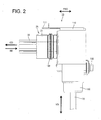
FIG. 2 is a right side view of the connector, -
FIG. 3 is a section along A-A ofFIG. 1 , -
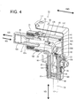
FIG. 4 is a perspective view in section of the internal structure of the connector when viewed obliquely from above, -
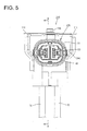
FIG. 5 is a front view of a connector of a second embodiment, -
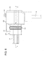
FIG. 6 is a right side view of the connector, -
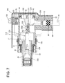
FIG. 7 is a section along B-B ofFIG. 5 , -
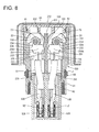
FIG. 8 is a section along C-C ofFIG. 6 , -
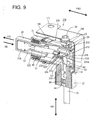
FIG. 9 is a perspective view in section of the internal structure of the connector when viewed obliquely from above, -
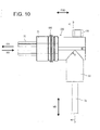
FIG. 10 is a right side view of the connector in a state where a shield shell is removed, -
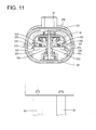
FIG. 11 is a rear view viewed from behind showing a state where a cover of the connector ofFIG. 10 is removed, and -
FIG. 12 is a section along D-D ofFIG. 10 . - A first particular embodiment of the present invention is described with reference to
FIGS. 1 to 4 . Aconnector 10 of this embodiment is to be mounted on a shield case (not shown) of a device (e.g. inverter, motor or the like of a vehicle such as a hybrid vehicle or an electric vehicle). A device-side connector (mating connector) connectable to theconnector 10 is arranged at a position substantially facing theconnector 10 in a connecting direction in the shield case. Note that a vertical direction VD is based on that ofFIG. 1 in the following description. Further, forward and backward directions FBD are based on lateral directions ofFIG. 2 , wherein a leftward direction (connecting direction CD to the device-side connector) is referred to as a forward direction and a rightward direction (separating direction SD from the device-side connector) is referred to as a backward direction. - As shown in
FIG. 4 , theconnector 10 includes one or more of the following: ahousing 20, one or more innerconductive members 50, acover 60,outer wires 70, one or more resilient orrubber plugs 80, a resilient orrubber plug presser 90, alower member 100, anupper member 110, one or more fixing members (particularly fixing screws) 140, a coupling member (particularly coupling screw) 150 and the like. A terminal accommodatingportion 30 at least partly fittable into the device-side connector is provided in thehousing 20. - The inner
conductive member 50 includes a flexibleinner wire 51 substantially extending in forward and backward directions FBD, a female terminal 52 (as a particular terminal fitting) connected to (particularly a front end part of) theinner wire 51, anintermediate terminal 53 connected to another part (particularly a rear end part) of theinner wire 51 and the like. Thefemale terminal 52 is to be held and retained in theterminal accommodating portion 30. One or more, particularly a pair of innerconductive members 50 are provided (particularly substantially side by side in the lateral direction), and the one or more, particularly the pair of adjacent innerconductive members 50 are to be at least partly accommodated in theterminal accommodating portion 30 in a state insulated particularly from each other. - The
female terminal 52 includes a terminal connectingportion 52A (particularly substantially in the form of a rectangular or polygonal tube) to be connected to a male terminal (not shown) provided in the device-side connector and a wire connection portion (particularly comprising at least onebarrel portion 52B) connected behind thisterminal connecting portion 52A and to be electrically connected (particularly crimped, folded or bent and connected) to (particularly the front end part of) theinner wire 51. - On the other hand, the
intermediate terminal 53 is bent at at an angle different from 0° or 180°, preferably substantially normal and/or substantially L-shaped as a whole and includes an inner wire connection portion (particularly comprising an innerwire crimping portion 53A) to be electrically connected (particularly crimped and connected) to the other part (particularly the rear end part) of theinner wire 51, an outer wire connection portion (particularly comprising an outerwire crimping portion 53B) to be connected (particularly crimped and connected) to (particularly an upper or distal end part of) the (particularly substantially vertically extending)outer wire 70, and anintermediate portion 53C connecting the inner and outer wire connection portions (particularly the inner and outerwire crimping portions intermediate terminal 53 is formed into an L-shape or bent shape by bending theintermediate portion 53C at least at one position at an angle different from 0° or 180°, preferably substantially at a right angle. - Note that although the
inner wire 51 is crimped to thefemale terminal 52 and theintermediate terminal 53 in this embodiment, there is no limitation to this and theinner wire 51 may be connected to thefemale terminal 52 and theintermediate terminal 53 by various known connection means such as brazing, soldering and/or welding. Similarly, the connection of theintermediate terminal 53 and theouter wire 70 is not limited to crimp connection described above and may be made by various other known connection methods such as welding. - The
outer wire 70 is such a wire that a core (particularly made up of a plurality of conductive or metal strands) is at least partly covered with an insulation coating. Theouter wire 70 is flexible and deflectable in a direction intersecting with an axial direction. Thus, a part of vibration transmitted from a body is absorbed by the deflection of theouter wire 70 and vibration, which cannot be absorbed by theouter wire 70, is transmitted to theintermediate terminal 53. - The
housing 20 is made e.g. of synthetic resin, particularly substantially L-shaped when viewed sideways and/or configured such that afitting portion 21 at least partly fittable into a case-side opening of the shield case and awire pullout portion 22 in which theouter wires 70 are pulled out laterally or downward are arranged in opposite end parts and/or coupled to each other as shown inFIG. 3 . A front portion (particularly a substantially front half) of theterminal accommodating portion 30 projects forward (or in the connection direction CD) from the front surface of thefitting portion 21. Further, thewire pullout portion 22 includes one or more, particularly a pair ofindependent accommodation spaces 23 capable of individually accommodating the respective one or more, particularly the pair ofouter wires 70. The resilient or rubber plugs 80 and the resilient orrubber plug presser 90 are to be at least partly accommodated in thewire pullout portion 22. - The resilient or rubber plugs 80 are seal members made of a resilient material such as a rubber material for individually making the respective
outer wires 70 fluid- or watertight, and sandwiched (particularly substantially over the entire circumference) between the outer peripheral surfaces of the outer wire(s) 70 and the inner peripheral surface of thewire pullout portion 22. Further, the resilient orrubber plug presser 90 is to be held and retained in thewire pullout portion 22. In this way, the resilient or rubber plugs 80 particularly are held in thewire pullout portion 22 by the resilient orrubber plug presser 90 while sealing theaccommodation spaces 23 of thewire pullout portion 22. - The
housing 20 particularly is at least partly covered by a shield shell made of an electrically conductive (particularly metal) plate or sheet material. This shield shell particularly is made of metal such as iron plate, aluminum or aluminum alloy and formed by at least assembling the lower member 100 (first member) and the upper member 110 (second member) with each other. Thelower member 100 mainly covers thewire pullout portion 22 and theupper member 110 mainly covers thefitting portion 21. Further, theupper member 110 is formed with at least one mountingportion 111 to be mounted and fixed to the shield case. As shown inFIG. 3 , ashell coupling portion 27 into which at least one fixingnut 25 is fixed or mounted (particularly press-fitted) is formed on the rear surface of thehousing 20. - The
lower member 100 and theupper member 110 particularly are arranged one over the other on theshell coupling portion 27, and the bothmembers housing 20 particularly by inserting the at least onecoupling screw 150 through screw insertion holes respectively formed in the bothmembers - At least one mounting groove in which at least one
seal ring 180 is to be mounted particularly is circumferentially provided on the outer peripheral surface of thewire pullout portion 22. Thisseal ring 180 is to be sandwiched over the entire circumference between the bottom surface of the mounting groove and the inner surface of the case-side opening when thefitting portion 21 is fitted into the case-side opening. In this way, the interior of the shield case is held in a sealed state. - Further, at least one mounting groove in which at least one
seal ring 181 is to be mounted is circumferentially provided on the outer peripheral surface of thewire pullout portion 22. Thisseal ring 181 is to be sandwiched over the entire circumference between the bottom surface of the mounting groove and the inner surface of thelower member 100 when thelower member 100 of the shield shell is externally fitted to thewire pullout portion 22. In this way, the interior of thelower member 100 is held in a sealed state. - In the
housing 20, aterminal fixing portion 24 is arranged in a (particularly substantially right-angled) corner portion coupling thefitting portion 21 and thewire pullout portion 22, and one or more nuts (not shown) particularly are press-fitted into thisterminal fixing portion 24. The intermediate portion(s) 53C of the intermediate terminal(s) 53 is/are arranged on this/these nut(s) and the one or more fixing screws 140 are inserted through respective round hole(s) formed in the intermediate portion(s) 53C and tightened into the nut(s), whereby the intermediate terminal(s) 53 particularly is/are fixed to theterminal fixing portion 24. In this way, vibration and the like transmitted from the outer wire(s) 70 are blocked by theterminal fixing portion 24 built in thehousing 20. Even if all the vibration and the like cannot be blocked by thehousing 20, the inner wire(s) 51 located before theterminal fixing portion 24 particularly is/are deflected to absorb all the remaining vibration and the like, wherefore contact portion(s) of the male terminal(s) and the female terminal(s) 52 is/are not affected. - Further, the intermediate portion(s) 53C of the intermediate terminal(s) 53 particularly is/are arranged along or adjacent to the corner portion of the
terminal fixing portion 24. If it is attempted to bend the outer wire 70 (particularly substantially at a right angle) in the corner portion of theterminal fixing portion 24, a bending angle of theouter wire 70 becomes larger and theouter wire 70 can be no longer accommodated in thehousing 20. In that respect, since theintermediate portion 53C made of a conductive (particularly metal) plate material is provided with a (particularly substantially right-angled) bent portion in this embodiment, the bending radius of theintermediate portion 53C can be made as small as possible. This can contribute to the miniaturization of theconnector 10. - As shown in
FIG. 3 , anoperation hole 62 to which thecover 60 is to be mounted is formed in correspondence with (particularly substantially behind) theterminal fixing portion 24 in thehousing 20. Thecover 60 particularly includes aseal ring 61 which comes into close contact with the inner peripheral surface of theoperation hole 62 to seal the interior of thehousing 20. The one or more, particularly the pair of fixingscrews 140 at least partly are exposed to outside through theoperation hole 62. Thus, the fixing screw(s) 140 can be easily tightened by inserting a tool such as a hexagonal wrench through theoperation hole 62. After an operation is finished, thecover 60 is mounted to theoperation hole 62, whereby the interior of thehousing 20 can be held in a sealed state. - Next, functions of this embodiment configured as described above are described. First, after being inserted through the
lower member 100, the (particularly two) outer wire(s) 70 is/are at least partly inserted into thehousing 20 through theoperation hole 62 by being inserted into the accommodation space(s) 23 of thehousing 20 from thewire pullout portion 22. Further, the female terminal(s) 52 are connected (particularly crimped into connection) to one end side(s) of the inner wire(s) 51 and the intermediate terminal(s) 53 is/are connected (particularly crimped into connection) to the other end side(s) to form the inner conductive member(s) 50. Further, the outer wire(s) 70 particularly is/are fixed by being connected (particularly crimped) to the wire connection portion(s) (particularly the outer wire crimping portion(s)) of the intermediate terminal(s) 53. Thereafter, when the female terminal(s) 52 is/are at least partly inserted into thehousing 20 through theoperation hole 62, inserted into the terminal accommodating portion 30 (particularly substantially from behind) and inserted up to proper position(s) in theterminal accommodating portion 30, it is or they are retained by one or more locking lances formed (particularly substantially in a cantilever manner) in or on theterminal accommodating portion 30. Associated with this, the intermediate terminal(s) 53 at least partly is/are inserted into thehousing 20 through theoperation hole 62 and the intermediate portion(s) 53C is/are arranged substantially along the corner portion of theterminal fixing portion 24. Then, as the fixing screw(s) 140 is/are tightened into screw hole(s) of the nut(s) through the round hole(s) of the intermediate portion(s) 53C with the round hole(s) substantially coaxially aligned with the screw hole(s) of the nut(s), the intermediate terminal(s) 53 is/are fixed to theterminal fixing portion 24. - Further, the one or more resilient or rubber plugs 80 already fitted on the respective outer wire(s) 70 are fitted through a lower end opening of the
lower member 100 and the resilient orrubber plug presser 90 is mounted below the resilient or rubber plug(s) 80 to hold the resilient or rubber plugs 80. Thereafter, thecover 60 particularly is mounted to substantially close theoperation hole 62 and the interior of thehousing 20 is sealed by theseal ring 61. - Subsequently, the
lower member 100 having the outer wire(s) 70 inserted therethrough particularly is externally mounted on thewire pullout portion 22 of thehousing 20. Further, theupper member 110 particularly is mounted from the rear side of thehousing 20. Then, therespective members shell coupling portion 27 and thecoupling screw 150 particularly is tightened into the fixingnut 25 to fix therespective members housing 20. In this way, the bothmembers housing 20 at least partly is covered by this shield shell. - As described above, according to this embodiment, vibration can be absorbed by fixing the inner conductive member(s) 50 to the
housing 20 while absorbing the vibration by the flexible outer wire(s) 70. Further, since the intermediate portion(s) 53C of the inner conductive member(s) 50 is/are made of the conductive (metal) plate material, the bending radius can be made smaller and theconnector 10 can be miniaturized. - The inner
conductive member 50 may be composed of theinner wire 51 and theintermediate terminal 53 connected to thisinner wire 51 to form theintermediate portion 53C, and thisintermediate terminal 53 may include the inner wire connection portion (particularly the innerwire crimping portion 53A) arranged at one side of theintermediate portion 53C to be connected (particularly crimped) to theinner wire 51 and the outer wire connection portion (particularly the outerwire crimping portion 53B) arranged at the other side to be connected (particularly crimped) to theouter wire 70. - According to such a configuration, the
intermediate portion 53C can be substantially formed into a bent shape, particularly an L-shape. For example, in the case of fastening a round terminal connected to theinner wire 51 and a round terminal connected to theouter wire 70 together for connection, a pair of terminals connected to therespective wires intermediate terminal 53, which leads to a reduction in the number of components. Further, it is not necessary to fasten the pair of round terminals together by theterminal fixing portion 24, and it is sufficient to insert the fixingscrew 140 through the round hole of theintermediate portion 53C and tighten it into theterminal fixing portion 24. Thus, operability is good. - A part of the
intermediate portion 53C to be fixed to thehousing 20 may be arranged to be substantially flush with the outerwire crimping portion 53B and fastened to thehousing 20 by the fixingscrew 140. - According to such a configuration, since the
intermediate portion 53C is arranged at the side of the outerwire crimping portion 53B susceptible to vibration, the impact of vibration is easily blocked. Further, a fastening direction by the fixingscrew 140 particularly substantially is perpendicular to a vibration transmission direction and, hence, the impact of vibration is more easily blocked. - Accordingly, to enable the miniaturization of a connector while absorbing vibration from a body side, there is provided a
connector 10 connectable to a mating connector. Theconnector 10 includes ahousing 20 connectable to a mating housing of the mating connector, a female terminal 52 (as a particular terminal) held in thehousing 20 and including aterminal connecting portion 52A to be connected to a mating terminal provided in the mating connector and a connection portion (particularly comprising abarrel portion 52B) connected to theterminal connecting portion 52A, a flexibleouter wire 70 pulled out to outside from the interior of thehousing 20, and an innerconductive member 50 configured to connect the connection portion (particularly thebarrel portion 52B) and theouter wire 70 in thehousing 20 and including an intermediate (bent)portion 53C formed by bending a conductive (particularly metal) plate material at an angle different from 0° or 180°, preferably substantially at a right angle, theintermediate portion 53C being fixed to thehousing 20. - Next, a second particular embodiment of the present invention is described with reference to
FIGS. 5 to 12 . This embodiment differs from the first embodiment in that intermediate terminal(s) is/are fixed to a housing by being press-fitted. Configurations, functions and effects similar or common to the first embodiment are not described and the same reference signs as in the first embodiment are used. - As shown in
FIG. 9 , aconnector 210 includes one or more of the following: ahousing 220, one or more innerconductive members 230, acover 60, one or moreouter wires 70, one or more resilient or rubber plugs 80, a resilient orrubber plug presser 90, one or more fixing screws 140, at least onecoupling screw 150, ashield shell 240 and the like. Aterminal accommodating portion 30 at least partly fittable into a device-side connector is provided in or on thehousing 220. Theterminal accommodating portion 30 is retained so as not to come out forward by aretainer 40 as shown inFIG. 8 . - As shown in
FIG. 7 , theshield shell 240 is an integral assembly of thelower member 100 and theupper member 110 in the first embodiment and covers theentire housing 220. Note that, in this embodiment, particularly noseal ring 181 is provided between awire pullout portion 22 and theshield shell 240. - A
shell fixing portion 26 into which a fixingnut 25 is provided (particularly press-fitted) is formed on (particularly the upper surface of) thehousing 220. Theshield shell 240 is placed on thisshell fixing portion 26 and theshield shell 240 is to be fixed to thehousing 220 by inserting a mountingscrew 130 through a screw insertion hole formed in the upper surface of thisshield shell 240 and tightening it into the fixingnut 25. Note that, in this embodiment, theshell coupling portion 27 of the first embodiment particularly is not provided. - The inner
conductive member 230 of this embodiment includes a flexibleinner wire 51 substantially extending in forward and backward directions FBD, afemale terminal 52 connected to (particularly a front end part of) theinner wire 51, anintermediate terminal 231 connected to another part (particularly a rear end part) of theinner wire 51 and the like. As shown inFIG. 8 , thefemale terminal 52 is held and retained in theterminal accommodating portion 30 by a locking lance 35, particularly substantially formed in a cantilever manner. One or more, particularly a pair of innerconductive members 230 are provided (particularly substantially side by side in the lateral direction), and particularly the pair of adjacent innerconductive members 230 are accommodated in theterminal accommodating portion 30 in a state insulated from each other. - One or more, particularly a pair of
intermediate terminals 231 are provided (particularly substantially side by side in the lateral direction) and the respective intermediate terminal(s) 231 at least partly is/are accommodated in corresponding accommodation space(s) 23. Specifically, the pair of adjacentintermediate terminals 231 at least partly are partitioned by at least onepartition wall 221 partitioning a pair ofadjacent accommodation spaces 23. In this way, a creepage distance (insulating property) between the pair of adjacentintermediate terminals 231 is ensured. - As shown in
FIG. 9 , theintermediate terminal 231 substantially is bent or L-shaped as a whole and includes an inner wire connection portion (particularly comprising an inner wire crimping portion 232) connectable (particularly to be crimped and connected) to (particularly a rear end part of) theinner wire 51, an outer wire connection portion (particularly comprising an outer wire crimping portion 233) connectable (particularly to be crimped and connected) to another part (particularly an upper or distal end part) of the (particularly substantially vertically extending)outer wire 70, and anintermediate portion 234 connecting the inner and outer wire connection portions, particularly the inner and outerwire crimping portions intermediate terminal 231 is bent (particularly substantially formed into an L-shape) by bending theintermediate portion 234 at an angle different from 0° or 180°, preferably substantially at a right angle. One or more, particularly a pair of press-fit projections 235 are formed to protrude from at least one lateral part (particularly substantially opposite lateral (left and right) side edges) of ahorizontal portion 234A of theintermediate portion 234 particularly substantially flush with the innerwire crimping portion 232. - On the other hand, as shown in
FIGS. 11 and12 , one or more, particularly a pair of terminal fixingportions 222 are provided on one or more side walls (particularly at substantially opposite sides) of theintermediate terminal 231 in thehousing 220. One or more, particularly a plurality of press-fit recesses 223 into which the respective press-fit projection(s) 235 is/are to be press-fitted (particularly substantially from behind) are formed on this/these terminal fixing portion(s) 222. When the respective press-fit projection(s) 235 is/are press-fitted into the respective press-fit recess(es) 223, the respective intermediate terminal(s) 231 is/are fixed to thehousing 220. - In this way, vibration and the like transmitted from the outer wire(s) 70 are blocked by the terminal fixing portion(s) 222 built in or mounted to the
housing 220. Particularly, a press-fit direction of each press-fit projection particularly substantially is perpendicular to a vibration transmission direction and, hence, the impact of vibration is more easily blocked. Even if all the vibration or the like cannot be blocked by thehousing 220, the inner wire(s) 51 located before the terminal fixing portion(s) 222 absorb all the remaining vibration and the like, wherefore contact portion(s) of male terminal(s) and the female terminal(s) 52 are not affected. - As described above, in this embodiment, the intermediate terminal(s) 231 particularly can be fixed to the
housing 220 by an easy press-fit method. Thus, it is not necessary to provide a terminal block such as by press-fitting nut(s) into thehousing 220 and thehousing 220 can be miniaturized. - The present invention is not limited to the above described and illustrated embodiments. For example, the following embodiments are also included in the technical scope of the present invention.
- (1) Although the substantially L-shaped intermediate terminal in which the inner and outer wire crimping portions are arranged at the opposite sides of the intermediate portion is illustrated in the above embodiment, it is sufficient that the intermediate portion is formed by bending the metal plate material substantially at a right angle and the arrangement of the inner and outer wire crimping portions does not matter according to the present invention.
- (2) Although the
inner wire 51 is connected to one end of the intermediate terminal and thisinner wire 51 is connected to thefemale terminal 52 in the above embodiments, theinner wire 51 may be omitted and thefemale terminal 52 may be directly connected to one end of the intermediate terminal according to the present invention. - (3) Although the intermediate portion of the intermediate terminal is fixed to the housing in the above embodiments, it may be made integral to the housing in advance by insert molding according to the present invention.
- (4) Although the
inner wire 51 and theouter wire 70 are respectively crimped and connected to the respective crimping portions of theintermediate terminal 53 in the above embodiments, they may be directly connected to the intermediate portion, for example, by ultrasonic welding, soldering, brazing or the like according to the present invention. -
- 10
- connector
- 20, 220
- housing
- 24, 222
- terminal fixing portion
- 50, 230
- inner conductive member
- 51
- inner wire
- 52
- female terminal
- 52A
- terminal connecting portion
- 52B
- barrel portion (conductor connecting portion)
- 53, 231
- intermediate terminal
- 53A, 232
- inner wire crimping portion
- 53B, 233
- outer wire crimping portion
- 53C, 234
- intermediate portion
- 70
- outer wire
- 140
- fixing screw
Claims (15)
- A connector (10) connectable to a mating connector, comprising:a housing (20; 220) connectable to a mating housing of the mating connector;at least one terminal (52) held in the housing (20; 220) and including a terminal connecting portion (52A) to be connected to a mating terminal provided in the mating connector and a conductor connecting portion (52B) connected to the terminal connecting portion (52A);a flexible outer wire (70) pulled out to outside from the interior of the housing (20; 220); andan inner conductive member (50; 230) configured to connect the conductor connecting portion (52B) and the outer wire in the housing (20; 220) and including a bent intermediate portion (53C; 234) formed by bending a conductive plate material, the intermediate portion (53C; 234) being fixed to the housing (20; 220).
- A connector according to claim 1, wherein the bent intermediate portion (53C; 234) is formed by bending a conductive plate material substantially at a right angle.
- A connector according to any one of the preceding claims, wherein the inner conductive member (50; 230) includes an inner wire (51) and an intermediate terminal (53; 231) connected to the inner wire (51) to form the intermediate portion (53C; 234).
- A connector according to claim 3, wherein the intermediate terminal (53; 231) includes an inner wire fixing portion (53A; 232) arranged at one side of the intermediate portion (53C; 234) to be fixed to the inner wire (51) and an outer wire fixing portion (53B; 233) arranged at the other side to be fixed to the outer wire (70).
- A connector according to claim 3 or 4, wherein a part of the intermediate portion (53C; 234) to be fixed to the housing (20; 220) is arranged to be flush with the outer wire fixing portion (53B; 233).
- A connector according to any one of the preceding claims, wherein the intermediate portion (53C; 234) is fastened to the housing (20; 220) by a screw.
- A connector according to any one of the preceding claims, wherein the intermediate portion (53C; 234) is press-fitted into the housing (20; 220).
- A connector according to any one of the preceding claims, wherein the housing (20; 220) is at least partly covered by a shield shell made of an electrically conductive plate or sheet material.
- A connector according to claim 8, wherein the shield shell comprises a first member (100) and a second member (110) to be assembled with each other, wherein the second member (110) is formed with at least one mounting portion (111) to be mounted and fixed to the shield case.
- A connector according to any one of the preceding claims, wherein at least one mounting groove in which at least one seal ring (180; 181) is to be mounted is provided on a wire pullout portion (22) in which the outer wire (70) is pulled out from the housing (20; 220).
- A connector according to any one of the preceding claims, further comprising an operation hole (62) to which a cover (60) is to be mounted is formed in correspondence with the terminal fixing portion (24) in the housing (20).
- A connector according to claim 11, wherein the cover (60) includes a seal ring (61) which comes into close contact with the inner peripheral surface of the operation hole (62) to seal the interior of the housing (20).
- A connector according to any one of the preceding claims, wherein at leaast one pair of intermediate terminals (231) are provided and the respective intermediate terminals (231) at least partly are accommodated in corresponding accommodation spaces (23), wherein the pair of adjacent intermediate terminals (231) at least partly are partitioned by at least one partition wall (221) partitioning a pair of adjacent accommodation spaces (23).
- A connector according to any one of the preceding claims, wherein the intermediate portion (53C; 234) is fixed to the housing (20; 220) in a fastening direction which substantially is perpendicular to a vibration transmission direction.
- A method of producing a connector (10) connectable to a mating connector, the method comprising the following steps:providing a housing (20; 220) connectable to a mating housing of the mating connector;holding at least one terminal (52) in the housing (20; 220), the terminal (52) including a terminal connecting portion (52A) to be connected to a mating terminal provided in the mating connector and a conductor connecting portion (52B) connected to the terminal connecting portion (52A);pulling out a flexible outer wire (70) to outside from the interior of the housing (20; 220);connecting the conductor connecting portion (52B) and the outer wire in the housing (20; 220) by an inner conductive member (50; 230) including a bent intermediate portion (53C; 234) formed by bending a conductive plate material, andfixing the intermediate portion (53C; 234) to the housing (20; 220).
Applications Claiming Priority (1)
| Application Number | Priority Date | Filing Date | Title |
|---|---|---|---|
| JP2012181392A JP2014038793A (en) | 2012-08-20 | 2012-08-20 | Connector |
Publications (2)
| Publication Number | Publication Date |
|---|---|
| EP2701245A2 true EP2701245A2 (en) | 2014-02-26 |
| EP2701245A3 EP2701245A3 (en) | 2015-02-18 |
Family
ID=48698878
Family Applications (1)
| Application Number | Title | Priority Date | Filing Date |
|---|---|---|---|
| EP20130003240 Withdrawn EP2701245A3 (en) | 2012-08-20 | 2013-06-25 | Connector and producing method therefor |
Country Status (4)
| Country | Link |
|---|---|
| US (1) | US9124024B2 (en) |
| EP (1) | EP2701245A3 (en) |
| JP (1) | JP2014038793A (en) |
| CN (1) | CN103633466A (en) |
Cited By (3)
| Publication number | Priority date | Publication date | Assignee | Title |
|---|---|---|---|---|
| WO2018011341A1 (en) * | 2016-07-14 | 2018-01-18 | Te Connectivity Germany Gmbh | Vibration-attenuating connector with an oscillation absorber |
| WO2021055776A1 (en) * | 2019-09-20 | 2021-03-25 | Emerson Electric Co. | System and method for enabling waste disposer to be coupled to alternative electric power sources |
| WO2021158557A1 (en) * | 2020-02-03 | 2021-08-12 | Emerson Electric Co. | System and method for enabling waste disposer with permanent magnet motor to be coupled to alternative electric power sources |
Families Citing this family (38)
| Publication number | Priority date | Publication date | Assignee | Title |
|---|---|---|---|---|
| DE102012212274B4 (en) * | 2012-07-13 | 2018-06-07 | Te Connectivity Germany Gmbh | Electric plug with seal and method of making the electrical connector |
| KR101938932B1 (en) * | 2012-10-15 | 2019-01-15 | 앱티브 테크놀러지스 리미티드 | Electrical connector |
| JP6061148B2 (en) * | 2013-11-28 | 2017-01-18 | 住友電装株式会社 | connector |
| JP6135502B2 (en) * | 2013-12-26 | 2017-05-31 | 株式会社オートネットワーク技術研究所 | connector |
| JP2015162327A (en) * | 2014-02-27 | 2015-09-07 | 住友電装株式会社 | waterproof connector |
| JP2015198033A (en) * | 2014-04-02 | 2015-11-09 | 住友電装株式会社 | connector |
| CN107112682B (en) | 2014-10-08 | 2019-10-08 | 株式会社自动网络技术研究所 | Connector |
| JP6344611B2 (en) * | 2015-03-31 | 2018-06-20 | 株式会社オートネットワーク技術研究所 | connector |
| JP6132868B2 (en) * | 2015-03-31 | 2017-05-24 | 矢崎総業株式会社 | connector |
| JP6545529B2 (en) * | 2015-05-26 | 2019-07-17 | 住友電装株式会社 | Waterproof connector |
| JP6601092B2 (en) * | 2015-09-24 | 2019-11-06 | 株式会社オートネットワーク技術研究所 | connector |
| JP6364434B2 (en) * | 2016-03-01 | 2018-07-25 | 矢崎総業株式会社 | Shield connector fixing structure |
| JP6195137B1 (en) * | 2016-04-11 | 2017-09-13 | 株式会社オートネットワーク技術研究所 | connector |
| CN107546550B (en) * | 2016-06-28 | 2020-07-28 | 富士康(昆山)电脑接插件有限公司 | Electric connector and combination thereof |
| CN106450833B (en) * | 2016-11-08 | 2019-01-08 | 四川永贵科技有限公司 | Motor and the curved formula multi-core connector of electric machine controller |
| JP6766605B2 (en) * | 2016-11-10 | 2020-10-14 | 株式会社オートネットワーク技術研究所 | Device connector |
| JP6709513B2 (en) * | 2017-07-04 | 2020-06-17 | 住友電装株式会社 | Terminal block |
| CN108258487A (en) * | 2017-12-01 | 2018-07-06 | 广州市恒吉电子科技有限公司 | A kind of tail portion encapsulating structure of curved formula rectangular insert |
| JP6649937B2 (en) | 2017-12-20 | 2020-02-19 | 矢崎総業株式会社 | Connector and electric wire with connector |
| JP6616815B2 (en) * | 2017-12-20 | 2019-12-04 | 矢崎総業株式会社 | Connector and electric wire with connector |
| US11152833B2 (en) * | 2018-07-23 | 2021-10-19 | Borgwarner Inc. | Electrical device having compact connector assembly suited for high power applications |
| JP7042421B2 (en) * | 2018-11-19 | 2022-03-28 | 株式会社オートネットワーク技術研究所 | Connector and wire harness with connector |
| JP7127507B2 (en) * | 2018-11-20 | 2022-08-30 | 住友電装株式会社 | connector |
| JP7014139B2 (en) * | 2018-11-27 | 2022-02-01 | 住友電装株式会社 | connector |
| JP7206906B2 (en) * | 2018-12-28 | 2023-01-18 | 株式会社オートネットワーク技術研究所 | Terminal modules and connectors |
| DE102019205781B4 (en) | 2019-04-23 | 2025-06-12 | Audi Ag | Drive device comprising an electric motor and an inverter and motor vehicle |
| JP7007332B2 (en) * | 2019-06-14 | 2022-01-24 | 矢崎総業株式会社 | Waterproof connector |
| JP7027011B2 (en) * | 2019-06-25 | 2022-03-01 | 矢崎総業株式会社 | connector |
| CN110239379A (en) * | 2019-07-19 | 2019-09-17 | 四川瑞可达连接系统有限公司 | A DC charging device |
| JP7276077B2 (en) * | 2019-11-01 | 2023-05-18 | 住友電装株式会社 | connector |
| JP7073425B2 (en) * | 2020-02-18 | 2022-05-23 | 矢崎総業株式会社 | connector |
| JP7359034B2 (en) * | 2020-02-26 | 2023-10-11 | 住友電装株式会社 | connector |
| JP7359035B2 (en) * | 2020-02-26 | 2023-10-11 | 住友電装株式会社 | connector |
| JP7460470B2 (en) * | 2020-07-17 | 2024-04-02 | 矢崎総業株式会社 | connector |
| JP2022136779A (en) * | 2021-03-08 | 2022-09-21 | 株式会社オートネットワーク技術研究所 | connector |
| JP7447857B2 (en) * | 2021-03-31 | 2024-03-12 | 住友電装株式会社 | Connectors and wire harnesses |
| JP7518106B2 (en) * | 2022-01-17 | 2024-07-17 | 矢崎総業株式会社 | Terminal connection structure and connector |
| JP2025123012A (en) * | 2024-02-09 | 2025-08-22 | 株式会社オートネットワーク技術研究所 | Connector and connector mounting structure |
Citations (1)
| Publication number | Priority date | Publication date | Assignee | Title |
|---|---|---|---|---|
| JP2000277217A (en) | 1999-03-19 | 2000-10-06 | Smk Corp | Floating connector |
Family Cites Families (9)
| Publication number | Priority date | Publication date | Assignee | Title |
|---|---|---|---|---|
| US3860315A (en) * | 1972-08-14 | 1975-01-14 | Anderson Power Products | Explosion proof connector |
| FR2758214B1 (en) * | 1997-01-08 | 1999-01-29 | Cinch Connecteurs Sa | FEMALE ELECTRIC CONTACT MEMBER |
| FR2783098B1 (en) * | 1998-09-08 | 2000-10-06 | Cinch Connecteurs Sa | FEMALE ELECTRIC CONTACT MEMBER |
| JP2002319455A (en) * | 2001-04-23 | 2002-10-31 | Auto Network Gijutsu Kenkyusho:Kk | Shield connector |
| JP2005019319A (en) * | 2003-06-27 | 2005-01-20 | Auto Network Gijutsu Kenkyusho:Kk | Connector for equipment |
| JP4632320B2 (en) * | 2007-11-09 | 2011-02-16 | 住友電装株式会社 | Connector for equipment |
| JP5467850B2 (en) * | 2009-12-03 | 2014-04-09 | 矢崎総業株式会社 | L-shaped connector |
| JP2014007133A (en) * | 2012-05-28 | 2014-01-16 | Auto Network Gijutsu Kenkyusho:Kk | Connector |
| JP2014022266A (en) * | 2012-07-20 | 2014-02-03 | Sumitomo Wiring Syst Ltd | Connector |
-
2012
- 2012-08-20 JP JP2012181392A patent/JP2014038793A/en not_active Abandoned
-
2013
- 2013-06-25 EP EP20130003240 patent/EP2701245A3/en not_active Withdrawn
- 2013-08-15 US US13/967,416 patent/US9124024B2/en not_active Expired - Fee Related
- 2013-08-19 CN CN201310362146.6A patent/CN103633466A/en active Pending
Patent Citations (1)
| Publication number | Priority date | Publication date | Assignee | Title |
|---|---|---|---|---|
| JP2000277217A (en) | 1999-03-19 | 2000-10-06 | Smk Corp | Floating connector |
Cited By (9)
| Publication number | Priority date | Publication date | Assignee | Title |
|---|---|---|---|---|
| WO2018011341A1 (en) * | 2016-07-14 | 2018-01-18 | Te Connectivity Germany Gmbh | Vibration-attenuating connector with an oscillation absorber |
| US10847928B2 (en) | 2016-07-14 | 2020-11-24 | Te Connectivity Germany Gmbh | Vibration-attentuating connector with an oscillation absorber |
| WO2021055776A1 (en) * | 2019-09-20 | 2021-03-25 | Emerson Electric Co. | System and method for enabling waste disposer to be coupled to alternative electric power sources |
| CN114728289A (en) * | 2019-09-20 | 2022-07-08 | 艾默生电气公司 | System and method for enabling a garbage disposer to be coupled to an alternate power source |
| US12012736B2 (en) | 2019-09-20 | 2024-06-18 | InSinkErator LLC | System and method for enabling waste disposer to be coupled to alternative electric power sources |
| US12595646B2 (en) | 2019-09-20 | 2026-04-07 | InSinkErator LLC | System and method for enabling waste disposer to be coupled to alternative electric power sources |
| WO2021158557A1 (en) * | 2020-02-03 | 2021-08-12 | Emerson Electric Co. | System and method for enabling waste disposer with permanent magnet motor to be coupled to alternative electric power sources |
| CN115038847A (en) * | 2020-02-03 | 2022-09-09 | 艾默生电气公司 | System and method for coupling a waste disposer having a permanent magnet motor to an alternative power source |
| US12110672B2 (en) | 2020-02-03 | 2024-10-08 | InSinkErator LLC | System and method for enabling waste disposer with permanent magnet motor to be coupled to alternative electric power sources |
Also Published As
| Publication number | Publication date |
|---|---|
| US20140051286A1 (en) | 2014-02-20 |
| JP2014038793A (en) | 2014-02-27 |
| US9124024B2 (en) | 2015-09-01 |
| CN103633466A (en) | 2014-03-12 |
| EP2701245A3 (en) | 2015-02-18 |
Similar Documents
| Publication | Publication Date | Title |
|---|---|---|
| EP2701245A2 (en) | Connector and producing method therefor | |
| US9209582B2 (en) | Connector | |
| CN102282732B (en) | Grounding connector and wiring harness including the grounding connector | |
| US7959469B2 (en) | Connector device and connector assembly | |
| CN102474051B (en) | L-shaped connector | |
| US9455525B2 (en) | Connector with flexible conductive member to isolate terminal from vibrations in a wire | |
| US9312626B2 (en) | Shield connector | |
| US20140120763A1 (en) | Connector | |
| CN103843208B (en) | Joint connector | |
| EP2019457A2 (en) | A device connector, connecting method and apparatus therefor | |
| US20120252272A1 (en) | Insulating structure for l-shaped terminal | |
| JP6043577B2 (en) | Shield connector | |
| JP5565946B2 (en) | connector | |
| JP2019220255A (en) | Terminal | |
| JP2002280131A (en) | Shield connector for device connection | |
| JP5170013B2 (en) | Shield connector | |
| CN105706310B (en) | The water proof structure of connector | |
| JP2011165428A (en) | Connector device | |
| US20050037665A1 (en) | Conductive path | |
| JP2015022968A (en) | connector | |
| JP5325698B2 (en) | Wire connection unit | |
| JP6762784B2 (en) | Electrical connector | |
| JP2002246104A (en) | Waterproof connector | |
| JP2007311216A (en) | Connector | |
| JP2017117728A (en) | Terminal connection structure of wiring harness |
Legal Events
| Date | Code | Title | Description |
|---|---|---|---|
| PUAI | Public reference made under article 153(3) epc to a published international application that has entered the european phase |
Free format text: ORIGINAL CODE: 0009012 |
|
| AK | Designated contracting states |
Kind code of ref document: A2 Designated state(s): AL AT BE BG CH CY CZ DE DK EE ES FI FR GB GR HR HU IE IS IT LI LT LU LV MC MK MT NL NO PL PT RO RS SE SI SK SM TR |
|
| AX | Request for extension of the european patent |
Extension state: BA ME |
|
| PUAL | Search report despatched |
Free format text: ORIGINAL CODE: 0009013 |
|
| AK | Designated contracting states |
Kind code of ref document: A3 Designated state(s): AL AT BE BG CH CY CZ DE DK EE ES FI FR GB GR HR HU IE IS IT LI LT LU LV MC MK MT NL NO PL PT RO RS SE SI SK SM TR |
|
| AX | Request for extension of the european patent |
Extension state: BA ME |
|
| RIC1 | Information provided on ipc code assigned before grant |
Ipc: H01R 13/533 20060101AFI20150115BHEP Ipc: H01R 13/52 20060101ALI20150115BHEP Ipc: H01R 13/447 20060101ALI20150115BHEP Ipc: H01R 24/20 20110101ALI20150115BHEP Ipc: H01R 103/00 20060101ALN20150115BHEP Ipc: H01R 13/6581 20110101ALN20150115BHEP Ipc: H01R 13/631 20060101ALN20150115BHEP |
|
| STAA | Information on the status of an ep patent application or granted ep patent |
Free format text: STATUS: THE APPLICATION IS DEEMED TO BE WITHDRAWN |
|
| 18D | Application deemed to be withdrawn |
Effective date: 20150819 |