EP2701170A1 - Bidirectional direct current electrical switching apparatus - Google Patents
Bidirectional direct current electrical switching apparatus Download PDFInfo
- Publication number
- EP2701170A1 EP2701170A1 EP13180655.6A EP13180655A EP2701170A1 EP 2701170 A1 EP2701170 A1 EP 2701170A1 EP 13180655 A EP13180655 A EP 13180655A EP 2701170 A1 EP2701170 A1 EP 2701170A1
- Authority
- EP
- European Patent Office
- Prior art keywords
- arc
- contact
- movable contact
- switching apparatus
- electrical switching
- Prior art date
- Legal status (The legal status is an assumption and is not a legal conclusion. Google has not performed a legal analysis and makes no representation as to the accuracy of the status listed.)
- Withdrawn
Links
- 230000002457 bidirectional effect Effects 0.000 title description 5
- 230000005291 magnetic effect Effects 0.000 claims abstract description 49
- 238000004891 communication Methods 0.000 claims abstract description 8
- 230000007246 mechanism Effects 0.000 claims abstract description 7
- 230000005294 ferromagnetic effect Effects 0.000 claims description 4
- 230000004907 flux Effects 0.000 description 25
- 229910000831 Steel Inorganic materials 0.000 description 17
- 239000010959 steel Substances 0.000 description 17
- 230000009977 dual effect Effects 0.000 description 4
- 230000001012 protector Effects 0.000 description 3
- 235000013290 Sagittaria latifolia Nutrition 0.000 description 2
- 230000008859 change Effects 0.000 description 2
- 235000015246 common arrowhead Nutrition 0.000 description 2
- 239000004020 conductor Substances 0.000 description 2
- XUIMIQQOPSSXEZ-UHFFFAOYSA-N Silicon Chemical compound [Si] XUIMIQQOPSSXEZ-UHFFFAOYSA-N 0.000 description 1
- 238000003491 array Methods 0.000 description 1
- 230000008033 biological extinction Effects 0.000 description 1
- 238000013461 design Methods 0.000 description 1
- 230000006872 improvement Effects 0.000 description 1
- 230000001788 irregular Effects 0.000 description 1
- 230000005415 magnetization Effects 0.000 description 1
- 238000000034 method Methods 0.000 description 1
- 238000012986 modification Methods 0.000 description 1
- 230000004048 modification Effects 0.000 description 1
- 230000008569 process Effects 0.000 description 1
- 238000000926 separation method Methods 0.000 description 1
- 229910052710 silicon Inorganic materials 0.000 description 1
- 239000010703 silicon Substances 0.000 description 1
- 238000012546 transfer Methods 0.000 description 1
Images




Classifications
-
- H—ELECTRICITY
- H01—ELECTRIC ELEMENTS
- H01H—ELECTRIC SWITCHES; RELAYS; SELECTORS; EMERGENCY PROTECTIVE DEVICES
- H01H9/00—Details of switching devices, not covered by groups H01H1/00 - H01H7/00
- H01H9/30—Means for extinguishing or preventing arc between current-carrying parts
- H01H9/34—Stationary parts for restricting or subdividing the arc, e.g. barrier plate
- H01H9/36—Metal parts
-
- H—ELECTRICITY
- H01—ELECTRIC ELEMENTS
- H01H—ELECTRIC SWITCHES; RELAYS; SELECTORS; EMERGENCY PROTECTIVE DEVICES
- H01H9/00—Details of switching devices, not covered by groups H01H1/00 - H01H7/00
- H01H9/30—Means for extinguishing or preventing arc between current-carrying parts
- H01H9/44—Means for extinguishing or preventing arc between current-carrying parts using blow-out magnet
- H01H9/443—Means for extinguishing or preventing arc between current-carrying parts using blow-out magnet using permanent magnets
-
- H—ELECTRICITY
- H01—ELECTRIC ELEMENTS
- H01H—ELECTRIC SWITCHES; RELAYS; SELECTORS; EMERGENCY PROTECTIVE DEVICES
- H01H9/00—Details of switching devices, not covered by groups H01H1/00 - H01H7/00
- H01H9/30—Means for extinguishing or preventing arc between current-carrying parts
- H01H9/46—Means for extinguishing or preventing arc between current-carrying parts using arcing horns
-
- H—ELECTRICITY
- H01—ELECTRIC ELEMENTS
- H01H—ELECTRIC SWITCHES; RELAYS; SELECTORS; EMERGENCY PROTECTIVE DEVICES
- H01H1/00—Contacts
- H01H1/12—Contacts characterised by the manner in which co-operating contacts engage
- H01H1/14—Contacts characterised by the manner in which co-operating contacts engage by abutting
- H01H1/20—Bridging contacts
-
- H—ELECTRICITY
- H01—ELECTRIC ELEMENTS
- H01H—ELECTRIC SWITCHES; RELAYS; SELECTORS; EMERGENCY PROTECTIVE DEVICES
- H01H33/00—High-tension or heavy-current switches with arc-extinguishing or arc-preventing means
- H01H33/02—Details
- H01H33/59—Circuit arrangements not adapted to a particular application of the switch and not otherwise provided for, e.g. for ensuring operation of the switch at a predetermined point in the AC cycle
- H01H33/596—Circuit arrangements not adapted to a particular application of the switch and not otherwise provided for, e.g. for ensuring operation of the switch at a predetermined point in the AC cycle for interrupting DC
-
- H—ELECTRICITY
- H01—ELECTRIC ELEMENTS
- H01H—ELECTRIC SWITCHES; RELAYS; SELECTORS; EMERGENCY PROTECTIVE DEVICES
- H01H83/00—Protective switches, e.g. circuit-breaking switches, or protective relays operated by abnormal electrical conditions otherwise than solely by excess current
- H01H83/08—Protective switches, e.g. circuit-breaking switches, or protective relays operated by abnormal electrical conditions otherwise than solely by excess current operated by reversal of DC
Definitions
- the disclosed concept pertains generally to electrical switching apparatus and, more particularly, to bidirectional direct current electrical switching apparatus, such as, for example, bidirectional direct current relays and circuit breakers.
- Plural parallel strings of series-connected direct current (DC) electrical generating modules can employ a fuse located in the positive conductor of each string.
- the fuse only protects against a reverse over current when the corresponding string shorts and is back fed by the other PV strings which are bussed together at a main DC bus in a combiner box.
- fuses are essentially useless in PV power systems since such fuses are sized at 125% and typically must open at 150% of full load current, while the maximum short circuit current for PV arrays does not significantly exceed 100% of full load current.
- fuses protect conductors, such as wires, from over currents. Over currents can only result from a back feed condition. Forward feed currents for silicon PV modules are typically limited to about 7.5 A by the structure of the PV modules, which cannot produce more than about 7.5 A even when short circuited. Therefore, string fuses are useless for providing protection from a forward feed fault, or bus faults that occur above the string fuses.
- the parallel strings of series-connected DC electrical generating modules supply DC power to the main DC bus in the combiner box.
- a substantial reverse over current can be caused when one of the strings shorts and is back fed by the other PV strings which are bussed together at the main DC bus.
- the reverse over current is the greatest when the short occurs just prior to the last DC electrical generating module in a string.
- arc extinction circuit interruption
- relatively high DC voltages e.g., without limitation, 300 VDC to 1500 VDC
- relatively low forward currents e.g., without limitation, about 1 A to about 10 A
- relatively higher reverse currents e.g., without limitation, up to about 300 A
- a direct current electrical switching apparatus comprises: a first arc runner; a second arc runner; a third arc runner; a fourth arc runner; a first contact in electrical communication with the first and third arc runners; a second contact in electrical communication with the second and fourth arc runners; a movable contact comprising a first portion and a second portion respectively cooperating with the first contact and the second contact to provide a closed contact position in which the movable contact electrically engages the first and second contacts, and an open contact position in which the movable contact is disengaged from the first and second contacts; a first arc chamber comprising a first end, an opposite second end, a first longitudinal axis therebetween, and a plurality of first arc plates between the first end and the opposite second end, the first arc plates having a first width measured in a direction normal to the first longitudinal axis, one of the first arc plates at the first end of the first arc chamber being prox
- number shall mean one or an integer greater than one (i. e., a plurality).
- the disclosed concept is described in association with a relay, although the disclosed concept is applicable to a wide range of electrical switching apparatus, such as circuit breakers.
- a direct current electrical switching apparatus such as the example relay 2 is shown.
- the relay 2 includes a first arc runner 4, a second arc runner 6, a third arc runner 8, and a fourth arc runner 10.
- a first (stationary) contact 12 is in electrical communication with the first and third arc runners 4,8.
- a second (stationary) contact 14 is in electrical communication with the second and fourth arc runners 6,10.
- a U-shaped (partially shown in Figures 4 and 5 ) movable contact 16 includes a first portion 18 (best shown in Figure 4 ) and a second portion 20 (best shown in Figure 5 ) respectively cooperating with the first contact I2 and the second contact 14 to provide a closed contact position (not shown, but see the armature position of points B, C, D and E of Figure 9 ; points C and D represent the closed contact position; points B and E represent the initial contact touch position) in which the movable contact 16 electrically engages the first and second contacts 12,14, and an open contact position (shown in Figures 4 and 5 ) in which the movable contact 16 is disengaged from the first and second contacts 12,14.
- the movable contact 16 bridges between the two sides of the example relay 2.
- the two stationary contacts 12,14 are on the arc runners 4,10 in the arc chambers 22,32, respectively.
- a first arc chamber 22 includes a first end 24, an opposite second end 26, a first longitudinal axis 28 therebetween, and a plurality of first arc plates 30 between the ends 24,26.
- the first arc plates 30 have a first width 31 measured in a direction normal to the first longitudinal axis 28.
- One 30A of the first arc plates 30 at the first end 24 of the first arc chamber 22 is proximate the first arc runner 4.
- Another one 30B of the first arc plates 30 at the opposite second end 26 of the first arc chamber 22 is proximate the second arc runner 6.
- a second arc chamber 32 includes a first end 34, an opposite second end 36, a second longitudinal axis 38 therebetween, and a plurality of second arc plates 40 between the first end 34 and the opposite second end 36 of the second arc chamber 32.
- the second arc plates 40 have a second width 41 measured in a direction normal to the second longitudinal axis 38.
- One 40A of the second arc plates 40 at the first end 34 of the second arc chamber 32 is proximate the third arc runner 8.
- Another one 40B of the second arc plates 40 at the opposite second end 36 of the second arc chamber 32 is proximate the fourth arc runner 10.
- An operating mechanism 42 (best shown in Figure 6 ) cooperates with the movable contact 16 to move the movable contact 16 between the closed contact position and the open contact position.
- a magnet assembly 44 cooperates with the first and second arc chambers 22,32 to establish generally oppositely directed magnetic fields 46 normal to the first and second longitudinal axes 28,38, normal to a first direction of a first arc 48 between the first contact 12 and the first portion 18 of the movable contact 16 as the movable contact 16 moves away from the closed contact position toward the open contact position, and normal to an opposite second direction of a second arc 50 between the second contact 14 and the second portion 20 of the movable contact 16 as the movable contact 16 moves away from the closed contact position toward the open contact position, in order that the generally oppositely directed magnetic fields 46 cause one of the first arc 48 and the second arc 50 to enter one of the first and second arc chambers 22,32, respectively, depending upon a direction of current flow between the first contact 12 and the second contact 14.
- the generally oppositely directed magnetic fields 46 cause one
- the example relay 2 is rated for a first magnitude of first current flowing from the first contact 12 through the movable contact 16 to the second contact 14 and for a second magnitude of opposite second current flowing from the second contact 14 through the movable contact 16 to the first contact 12.
- the second magnitude is greater than the first magnitude.
- the second width 41 is greater than the first width 31.
- a dual arc chamber 52 includes a first relatively narrow portion corresponding to the first arc chamber 22 and a second relatively wider portion corresponding to the second arc chamber 32 as best shown in Figure 2 .
- Each of the first and second arc chambers 22 and 32 comprises the plural, parallel arc plates 30 and 40 disposed between the arc runners 4,6 and 8,10, respectively.
- the arc runners 4,8 are electrically connected to each other and to the first contact 12 and power terminal 56, and the arc runners 6,10 are electrically connected to each other and to the second contact 14 and power terminal 58 as shown in Figures 3-5 .
- the movable contact 16 is carried by a magnetic latching actuator 54 (best shown in Figure 6 ) and includes the first and second portions 18,20 that respectively electrically engage the first and second contacts 12,14 in the closed position to close the relay 2, and that respectively electrically disconnect from the first and second contacts 12,14 to open the relay 2.
- the first power terminal 56 is electrically connected to the positive side of a high voltage DC power supply (not shown), and the second power terminal 58 is electrically connected to the negative side of that DC power supply (not shown).
- the magnetic field 46 across the first arc chamber 32 is directed out of the drawing page of Figure 4 .
- the two arcs 48,50 are respectively drawn between first contact 12 and the first movable contact portion 18 and between the second movable contact portion 20 and second contact 14.
- the two arcs 48,50 tend to expand and the force applied by the generally oppositely directed magnetic fields 46 in the respective arc chambers 22,32 move the first arc 48 rightward (with respect to Figure 4 ) along movable contact 16 toward the surface of opposite arc runner 6.
- the anode end of the first arc 48 moves around a short radius corner of the arc runner 4. Because an anode end of an arc moves more readily than does a cathode end of the arc, it is preferable that the anode end be that which traverses a more irregular surface, while the cathode end move along the flat surface of the movable contact 16.
- first arc 48 While first arc 48 is lengthening and increasing the voltage thereof, the opposite second arc 50 is also moving rightward (with respect to Figure 4 or leftward with respect to Figure 5 ) under the bias of the magnetic field 46 in the opposite arc chamber 32 but within a more confined area.
- first arc 48 attaches to the opposite arc runner 6 within the first arc chamber 22 common to first contact 12, establishes a current path through first arc 48 from the arc runner 4 to the arc runner 6, and therefore from the power terminal 56 to the power terminal 58.
- the arc 60 continues to move along the arc runners 4 and 6 driven by the corresponding permanent magnetic field 46, thereby lengthening and moving in proximity of the splitter plates 30.
- the arc 60 is first separated into intermediate length segments between the adjacent depending ends of arc plates 30C, and between arc plates 30C and 30D, and thereafter is split into smaller lengths as these segments move into the smaller gaps between splitter plates 30E and the adjacent splitter plates 30E, 30D or 30C.
- the increased arc voltage levels drive the arc current to zero to interrupt the DC power circuit.
- the generally oppositely directed magnetic fields 46 cause the first arc 48 to enter the first arc chamber 22 and cause the second arc 50 to avoid the second arc chamber 32.
- the generally oppositely directed magnetic fields 46 cause the first arc 48 to avoid the first arc chamber 22 and cause the second arc 50 to enter the second arc chamber 32.
- the magnet assembly 44 includes a first permanent magnet 66, a second permanent magnet 68, ferromagnetic frames 70, and an insulative case 72 including a first portion 74 holding the first arc chamber 22, and a second portion 76 holding the second arc chamber 32.
- the insulative case 72 partially surrounds the first and second arc chambers 22,32, and then is covered by the ferromagnetic frames 70.
- the first permanent magnet 66 has a magnetic polarity (S) facing the first arc chamber 22, and the second permanent magnet 68 has the same magnetic polarity (S) facing the second arc chamber 32. This results in the generally oppositely directed magnetic fields 46 in each arc chamber 22,32.
- An example voltage between the first and second power terminals 56,58 can be up to about 800 VDC.
- DC solar string and combiner box applications can employ a miniature relay or circuit breaker to replace fuses and provide a tripable/resetable device that can incorporate solar arc fault algorithms.
- a single electrical switching apparatus, such as the relay 2 can address about 600 VDC to about 750 VDC applications, while two such relays 2 in series can address about 1000 VDC to about 1500 VDC applications.
- the forward current through the string is less than about 7.5 A at a forward 600 DC voltage, and hence the string protector is rated at 10 A and 600 VDC forward voltage.
- the reverse short circuit fault current can be much greater and the string protector is rated at 300 A and 600 VDC reverse voltage.
- the first relatively narrow portion of the first arc chamber 22 is provided for the first arc 48 corresponding to interruption of the forward current ( Figures 2 and 4 )
- the second relatively wider portion of the second arc chamber 32 is provided for the second arc 50 (shown in the opposite direction for forward current) corresponding to interruption of the relatively much larger reverse current ( Figures 2 and 5 ).
- the magnitude of the forward current can be about 10 DC amperes, and the magnitude of the opposite reverse current can be about 300 DC amperes.
- the second width 41 is about three times greater than the first width 31.
- the operating mechanism 42 is the example latching magnetic actuator 54.
- the magnetic actuator 54 includes two coils 90,92 and provides magnetic latching.
- the magnetic latching actuator 54 includes a top steel plate 94, two permanent magnets 96,98, a steel tube 100, a bottom steel frame 102, and a steel armature 104 coupled to a non-magnetic pin or screw 106 coupled to the movable contact 16.
- a bobbin 108 carries the two coils 90,92.
- the first coil 90 is turned on and raises the magnetic force from point F to point A (above the contact spring force at point K). Then, the armature 104 moves upward ( Figure 8 ). At point B, the magnetic force on the armature 104 with the first coil 90 turned on is greater than the spring force at M, for example and without limitation, 200 grams to overcome the contact spring force for the movable contact 16. At point C, the first coil 90 is turned off and the upward hold force to latch the relay 2 closed is produced by the magnetic flux from the permanent magnets 96,98 ( Figure 7 ).
- the top curve (A to B to 600) represents the force versus stroke with the first coil 90 (COIL-1) turned on.
- the bottom curve (D to E to -400) represents the force versus stroke with the second coil 92 (COIL-2) turned on.
- the smooth center curve (C to F) represents the force versus stroke with both coils 90,92 turned off.
- the straight segmented center curve (K to L to M to N) represents the contact spring forces in the system.
- Figures 7 and 8 show the magnetic flux from the permanent magnets 96,98 and the magnetic flux from the coil 90 to explain how the armature 104 is latched at the bottom (with respect to Figure 7 ), and how it is un-latched and made to move up to the top (with respect to Figure 8 ).
- the two coils 90,92 are off at point F of Figure 9 .
- the magnetic flux from each permanent magnet 96,98 is shown as a dashed line with an arrow head.
- the armature top air gap 110 receives no permanent magnet flux, while the armature 104 and the bottom air gap ( Figure 7 ) receive two times the permanent magnet flux.
- the armature 104 and the bottom air gap receive twice the permanent magnet flux (upward from the first coil 90 with respect to Figure 8 ) less twice the downward (with respect to Figure 8 ) permanent magnet flux for a net zero magnetic flux.
- the steel armature 104 carries twice the permanent magnet flux in the downward direction in Figure 7 , and a net of twice the permanent magnet flux in the upward direction in Figure 8 .
- the steel parts (top steel plate 94, bottom steel frame 102 and legs 112 of the steel frame 102) carry one permanent magnet flux in the counter-clockwise direction in Figure 7 , and a net of one permanent magnet flux in the clockwise direction in Figure 8 .
- the flux in the permanent magnets 96,98 is constant and does not significantly change.
- the coil amp-turns (NI) causes the permanent magnet flux to transfer from the armature bottom air gap to the top air gap 110, and causes the net magnetic flux in the steel parts to change direction (armature 144, top steel plate 94, bottom steel frame 102, and legs 112 of the steel frame 102). Transferring the permanent magnet flux to a different path requires far less energy than changing the magnetization direction of the permanent magnets.
- a single coil configuration (not shown) employs a power source (not shown) connected "+ to -" for movement in one direction, and connected "- to +" for movement in the opposite direction.
- the two coils 90,92 are employed, one coil at a time.
- the first coil 90 produces magnetic flux upward through the armature 104 to get the armature 104 to move upward (with respect to Figure 7 ).
- the second coil 92 produces magnetic flux downward (with respect to Figure 7 ) through the armature to get the armature 104 to move downward (with respect to Figure 7 ). If the armature 104 pole face area is different at the top and bottom (with respect to Figure 7 ), then the latching force will be different at the top and bottom (with respect to Figure 7 ). Then, the two coils 90,92 could be different to produce different forces in the upward and downward (with respect to Figure 7 ) directions.
- the disclosed concept provides intrinsic bidirectional, relatively low DC switching, with no minimum interruption current.
- the arc runners 4,6,8,10 and arc plates 30,40 arrangement provide effective arc splitting and minimal back-striking.
- the magnetic field design of the dual arc chamber 52 defines a stable final split arc position, with negligible arc flash.
- a circuit breaker can employ the disclosed dual arc chamber 52, fixed contacts 10,12 and arc runners 4,6,8,10.
- a minimized arc chamber 22,32 achieves relatively higher voltage (e.g., without limitation, up to 1500 VDC; 750 VDC for one unit) DC switching in a miniature DC switching device, such as a circuit breaker, the example relay 2, a contactor, or a switch.
Landscapes
- Arc-Extinguishing Devices That Are Switches (AREA)
Abstract
Description
- The disclosed concept pertains generally to electrical switching apparatus and, more particularly, to bidirectional direct current electrical switching apparatus, such as, for example, bidirectional direct current relays and circuit breakers.
- Plural parallel strings of series-connected direct current (DC) electrical generating modules (e.g., without limitation, photovoltaic (PV) or solar generating modules) can employ a fuse located in the positive conductor of each string. The fuse only protects against a reverse over current when the corresponding string shorts and is back fed by the other PV strings which are bussed together at a main DC bus in a combiner box.
- It is known to employ fuses for over current protection in combination with diodes to block reverse current.
- It is believed that fuses are essentially useless in PV power systems since such fuses are sized at 125% and typically must open at 150% of full load current, while the maximum short circuit current for PV arrays does not significantly exceed 100% of full load current. In PV power systems, fuses protect conductors, such as wires, from over currents. Over currents can only result from a back feed condition. Forward feed currents for silicon PV modules are typically limited to about 7.5 A by the structure of the PV modules, which cannot produce more than about 7.5 A even when short circuited. Therefore, string fuses are useless for providing protection from a forward feed fault, or bus faults that occur above the string fuses.
- In a PV generating system, the parallel strings of series-connected DC electrical generating modules supply DC power to the main DC bus in the combiner box. A substantial reverse over current can be caused when one of the strings shorts and is back fed by the other PV strings which are bussed together at the main DC bus. The reverse over current is the greatest when the short occurs just prior to the last DC electrical generating module in a string.
- There is room for improvement in bidirectional electrical switching apparatus.
- There is a desire to provide arc extinction (circuit interruption) at relatively high DC voltages (e.g., without limitation, 300 VDC to 1500 VDC), at relatively low forward currents (e.g., without limitation, about 1 A to about 10 A), and at relatively higher reverse currents (e.g., without limitation, up to about 300 A).
- This need and others are met by embodiments of the disclosed concept in which a direct current electrical switching apparatus comprises: a first arc runner; a second arc runner; a third arc runner; a fourth arc runner; a first contact in electrical communication with the first and third arc runners; a second contact in electrical communication with the second and fourth arc runners; a movable contact comprising a first portion and a second portion respectively cooperating with the first contact and the second contact to provide a closed contact position in which the movable contact electrically engages the first and second contacts, and an open contact position in which the movable contact is disengaged from the first and second contacts; a first arc chamber comprising a first end, an opposite second end, a first longitudinal axis therebetween, and a plurality of first arc plates between the first end and the opposite second end, the first arc plates having a first width measured in a direction normal to the first longitudinal axis, one of the first arc plates at the first end of the first arc chamber being proximate the first arc runner, another one of the first arc plates at the opposite second end of the first arc chamber being proximate the second arc runner; a second arc chamber comprising a first end, an opposite second end, a second longitudinal axis therebetween, and a plurality of second arc plates between the first end and the opposite second end of the second arc chamber, the second arc plates having a second width measured in a direction normal to the second longitudinal axis, one of the second arc plates at the first end of the second arc chamber being proximate the third arc runner, another one of the second arc plates at the opposite second end of the second arc chamber being proximate the fourth arc runner; an operating mechanism cooperating with the movable contact to move the movable contact between the closed contact position and the open contact position; and a magnet assembly cooperating with the first and second arc chambers to establish generally oppositely directed magnetic fields normal to the first and second longitudinal axes, normal to a first direction of a first arc between the first contact and the first portion of the movable contact as the movable contact moves away from the closed contact position toward the open contact position, and normal to an opposite second direction of a second arc between the second contact and the second portion of the movable contact as the movable contact moves away from the closed contact position toward the open contact position, in order that the generally oppositely directed magnetic fields cause one of the first arc and the second arc to enter one of the first and second arc chambers, respectively, depending upon a direction of current flow between the first contact and the second contact, wherein the electrical switching apparatus is rated for a first magnitude of first current flowing from the first contact through the movable contact to the second contact and for a second magnitude of opposite second current flowing from the second contact through the movable contact to the first contact; wherein the second magnitude is greater than the first magnitude; and wherein the second width is greater than the first width.
- A full understanding of the disclosed concept can be gained from the following description of the preferred embodiments when read in conjunction with the accompanying drawings in which:
-
Figure 1 is an isometric view of a relay in accordance with embodiments of the disclosed concept. -
Figure 2 is a bottom isometric view of the relay ofFigure 1 with a bottom portion cut-away to show internal structures. -
Figure 3 is an isometric view of the arc runners and portions of the arc chambers of the relay ofFigure 2 . -
Figure 4 is a front isometric view of the relay ofFigure 1 with a front portion cut-away to show internal structures, -
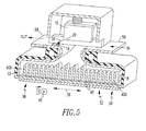
Figure 5 is a rear isometric view of the relay ofFigure 1 with a rear portion cut-away to show internal structures. -
Figure 6 is a cross-sectional isometric view of the latching magnetic actuator of the relay ofFigure 1 . -
Figures 7 and 8 are cross-sectional vertical elevation views of a portion of the latching magnetic actuator ofFigure 6 . -
Figure 9 is a plot of force versus armature stroke for the latching magnetic actuator ofFigure 6 . - As employed herein, the term "number" shall mean one or an integer greater than one (i. e., a plurality).
- As employed herein, the statement that two or more parts are "connected" or "coupled" together shall mean that the parts are joined together either directly or joined through one or more intermediate parts. Further, as employed herein, the statement that two or more parts are "attached" shall mean that the parts are joined together directly.
- The disclosed concept is described in association with a relay, although the disclosed concept is applicable to a wide range of electrical switching apparatus, such as circuit breakers.
- Referring to
Figures 1-5 , a direct current electrical switching apparatus, such as theexample relay 2 is shown. Therelay 2 includes a first arc runner 4, asecond arc runner 6, athird arc runner 8, and afourth arc runner 10. A first (stationary)contact 12 is in electrical communication with the first andthird arc runners 4,8. A second (stationary)contact 14 is in electrical communication with the second andfourth arc runners Figures 4 and5 )movable contact 16 includes a first portion 18 (best shown inFigure 4 ) and a second portion 20 (best shown inFigure 5 ) respectively cooperating with the first contact I2 and thesecond contact 14 to provide a closed contact position (not shown, but see the armature position of points B, C, D and E ofFigure 9 ; points C and D represent the closed contact position; points B and E represent the initial contact touch position) in which themovable contact 16 electrically engages the first andsecond contacts Figures 4 and5 ) in which themovable contact 16 is disengaged from the first andsecond contacts movable contact 16 bridges between the two sides of theexample relay 2. The twostationary contacts arc runners 4,10 in thearc chambers - A
first arc chamber 22 includes afirst end 24, an oppositesecond end 26, a firstlongitudinal axis 28 therebetween, and a plurality offirst arc plates 30 between theends first arc plates 30 have afirst width 31 measured in a direction normal to the firstlongitudinal axis 28. One 30A of thefirst arc plates 30 at thefirst end 24 of thefirst arc chamber 22 is proximate the first arc runner 4. Another one 30B of thefirst arc plates 30 at the oppositesecond end 26 of thefirst arc chamber 22 is proximate thesecond arc runner 6. Asecond arc chamber 32 includes afirst end 34, an oppositesecond end 36, a secondlongitudinal axis 38 therebetween, and a plurality ofsecond arc plates 40 between thefirst end 34 and the oppositesecond end 36 of thesecond arc chamber 32. Thesecond arc plates 40 have asecond width 41 measured in a direction normal to the secondlongitudinal axis 38. One 40A of thesecond arc plates 40 at thefirst end 34 of thesecond arc chamber 32 is proximate thethird arc runner 8. Another one 40B of thesecond arc plates 40 at the oppositesecond end 36 of thesecond arc chamber 32 is proximate thefourth arc runner 10. - An operating mechanism 42 (best shown in
Figure 6 ) cooperates with themovable contact 16 to move themovable contact 16 between the closed contact position and the open contact position. Amagnet assembly 44 cooperates with the first andsecond arc chambers magnetic fields 46 normal to the first and secondlongitudinal axes first arc 48 between thefirst contact 12 and thefirst portion 18 of themovable contact 16 as themovable contact 16 moves away from the closed contact position toward the open contact position, and normal to an opposite second direction of asecond arc 50 between thesecond contact 14 and thesecond portion 20 of themovable contact 16 as themovable contact 16 moves away from the closed contact position toward the open contact position, in order that the generally oppositely directedmagnetic fields 46 cause one of thefirst arc 48 and thesecond arc 50 to enter one of the first andsecond arc chambers first contact 12 and thesecond contact 14. InFigures 4 and5 , the generally oppositely directedmagnetic fields 46 are into or out of the drawing page. - As will be described, the
example relay 2 is rated for a first magnitude of first current flowing from thefirst contact 12 through themovable contact 16 to thesecond contact 14 and for a second magnitude of opposite second current flowing from thesecond contact 14 through themovable contact 16 to thefirst contact 12. The second magnitude is greater than the first magnitude. Thesecond width 41 is greater than thefirst width 31. - A
dual arc chamber 52 includes a first relatively narrow portion corresponding to thefirst arc chamber 22 and a second relatively wider portion corresponding to thesecond arc chamber 32 as best shown inFigure 2 . Each of the first andsecond arc chambers parallel arc plates arc runners arc runners 4,8 are electrically connected to each other and to thefirst contact 12 andpower terminal 56, and thearc runners second contact 14 andpower terminal 58 as shown inFigures 3-5 . Themovable contact 16 is carried by a magnetic latching actuator 54 (best shown inFigure 6 ) and includes the first andsecond portions second contacts relay 2, and that respectively electrically disconnect from the first andsecond contacts relay 2. - The
first power terminal 56 is electrically connected to the positive side of a high voltage DC power supply (not shown), and thesecond power terminal 58 is electrically connected to the negative side of that DC power supply (not shown). Themagnetic field 46 across thefirst arc chamber 32 is directed out of the drawing page ofFigure 4 . Upon separation, the twoarcs first contact 12 and the firstmovable contact portion 18 and between the secondmovable contact portion 20 andsecond contact 14. The twoarcs magnetic fields 46 in therespective arc chambers first arc 48 rightward (with respect toFigure 4 ) alongmovable contact 16 toward the surface ofopposite arc runner 6. The anode end of thefirst arc 48 moves around a short radius corner of the arc runner 4. Because an anode end of an arc moves more readily than does a cathode end of the arc, it is preferable that the anode end be that which traverses a more irregular surface, while the cathode end move along the flat surface of themovable contact 16. - While
first arc 48 is lengthening and increasing the voltage thereof, the oppositesecond arc 50 is also moving rightward (with respect toFigure 4 or leftward with respect toFigure 5 ) under the bias of themagnetic field 46 in theopposite arc chamber 32 but within a more confined area. Within a small interval of time, thefirst arc 48 attaches to theopposite arc runner 6 within thefirst arc chamber 22 common tofirst contact 12, establishes a current path throughfirst arc 48 from the arc runner 4 to thearc runner 6, and therefore from thepower terminal 56 to thepower terminal 58. - Inasmuch as
arc runner 8 in therear arc chamber 32 is common and electrically connected to the arc runner 4 in theforward arc chamber 22 to whichfirst contact 12 is electrically connected, the current path previously extending to themovable contact 16 from arc runner 4 and from themovable contact 16 toarc runner 8 is now eliminated and thesecond arc 50 is eliminated as well. Thereafter, a single arc 60 (Figure 4 ) progresses along the surfaces of the twoarc runners 4,6 within the forward arc chamber 22 (with respect toFigure 4 ) downward (with respect toFigure 4 ) into thearc splitter plates 30. Thearc 60 continues to move along thearc runners 4 and 6 driven by the corresponding permanentmagnetic field 46, thereby lengthening and moving in proximity of thesplitter plates 30. Thearc 60 is first separated into intermediate length segments between the adjacent depending ends ofarc plates 30C, and betweenarc plates splitter plates 30E and theadjacent splitter plates splitter plates - For forward current, the generally oppositely directed
magnetic fields 46 cause thefirst arc 48 to enter thefirst arc chamber 22 and cause thesecond arc 50 to avoid thesecond arc chamber 32. However, when the polarity of the DC current is reversed, the generally oppositely directedmagnetic fields 46 cause thefirst arc 48 to avoid thefirst arc chamber 22 and cause thesecond arc 50 to enter thesecond arc chamber 32. - Referring to
Figures 2-5 , themagnet assembly 44 includes a firstpermanent magnet 66, a secondpermanent magnet 68,ferromagnetic frames 70, and aninsulative case 72 including afirst portion 74 holding thefirst arc chamber 22, and a second portion 76 holding thesecond arc chamber 32. Theinsulative case 72 partially surrounds the first andsecond arc chambers - The first
permanent magnet 66 has a magnetic polarity (S) facing thefirst arc chamber 22, and the secondpermanent magnet 68 has the same magnetic polarity (S) facing thesecond arc chamber 32. This results in the generally oppositely directedmagnetic fields 46 in eacharc chamber - An example voltage between the first and
second power terminals relay 2, can address about 600 VDC to about 750 VDC applications, while twosuch relays 2 in series can address about 1000 VDC to about 1500 VDC applications. - For a 600 VDC solar string protector, such as a relay or miniature circuit breaker, the forward current through the string is less than about 7.5 A at a forward 600 DC voltage, and hence the string protector is rated at 10 A and 600 VDC forward voltage. However, the reverse short circuit fault current can be much greater and the string protector is rated at 300 A and 600 VDC reverse voltage. As a result, the first relatively narrow portion of the
first arc chamber 22 is provided for thefirst arc 48 corresponding to interruption of the forward current (Figures 2 and4 ), and the second relatively wider portion of thesecond arc chamber 32 is provided for the second arc 50 (shown in the opposite direction for forward current) corresponding to interruption of the relatively much larger reverse current (Figures 2 and5 ). - The magnitude of the forward current can be about 10 DC amperes, and the magnitude of the opposite reverse current can be about 300 DC amperes. In that instance, the
second width 41 is about three times greater than thefirst width 31. - The
operating mechanism 42 is the example latchingmagnetic actuator 54. Themagnetic actuator 54 includes twocoils Figures 6-8 , themagnetic latching actuator 54 includes atop steel plate 94, twopermanent magnets steel tube 100, abottom steel frame 102, and asteel armature 104 coupled to a non-magnetic pin or screw 106 coupled to themovable contact 16. Abobbin 108 carries the twocoils - As shown in
Figure 9 , thefirst coil 90 is turned on and raises the magnetic force from point F to point A (above the contact spring force at point K). Then, thearmature 104 moves upward (Figure 8 ). At point B, the magnetic force on thearmature 104 with thefirst coil 90 turned on is greater than the spring force at M, for example and without limitation, 200 grams to overcome the contact spring force for themovable contact 16. At point C, thefirst coil 90 is turned off and the upward hold force to latch therelay 2 closed is produced by the magnetic flux from thepermanent magnets 96,98 (Figure 7 ). The top curve (A to B to 600) represents the force versus stroke with the first coil 90 (COIL-1) turned on. The bottom curve (D to E to -400) represents the force versus stroke with the second coil 92 (COIL-2) turned on. The smooth center curve (C to F) represents the force versus stroke with bothcoils - When the
second coil 92 is turned on, this lowers the net magnetic force to point D (below the contact spring force at point N). As a result, thearmature 104 moves downward. At point E, the net magnetic force is less than the contact spring force at point L (0 grams) (i.e., is in a negative direction, which is downward with respect toFigure 8 ). Finally, thesecond coil 92 is turned off and the downward hold force to latch therelay 2 open is produced by the magnetic flux frompermanent magnets -
Figures 7 and 8 show the magnetic flux from thepermanent magnets coil 90 to explain how thearmature 104 is latched at the bottom (with respect toFigure 7 ), and how it is un-latched and made to move up to the top (with respect toFigure 8 ). Initially, inFigure 7 , the twocoils Figure 9 . The magnetic flux from eachpermanent magnet top air gap 110 receives no permanent magnet flux, while thearmature 104 and the bottom air gap (Figure 7 ) receive two times the permanent magnet flux. - Reversing the process (which is equivalent to holding
Figures 7 and 8 upside down) explains how thearmature 104 is latched at the top (with respect toFigure 7 ), and how it is un-latched and made to move down to the bottom (with respect toFigure 8 ). At point A ofFigure 9 , thefirst coil 90 is on. The magnetic flux from coil 90 (Figure 8 ) is shown as two dashed lines with arrow heads, in the opposite direction to the permanent magnet flux. Thearmature 104 top (with respect toFigure 8 )air gap 110 receives twice the permanent magnet flux from thefirst coil 90 less no permanent magnet flux for a net twice the permanent magnet flux upward (with respect toFigure 8 ). Thearmature 104 and the bottom air gap receive twice the permanent magnet flux (upward from thefirst coil 90 with respect toFigure 8 ) less twice the downward (with respect toFigure 8 ) permanent magnet flux for a net zero magnetic flux. Thesteel armature 104 carries twice the permanent magnet flux in the downward direction inFigure 7 , and a net of twice the permanent magnet flux in the upward direction inFigure 8 . The steel parts (top steel plate 94,bottom steel frame 102 andlegs 112 of the steel frame 102) carry one permanent magnet flux in the counter-clockwise direction inFigure 7 , and a net of one permanent magnet flux in the clockwise direction inFigure 8 . - The flux in the
permanent magnets top air gap 110, and causes the net magnetic flux in the steel parts to change direction (armature 144,top steel plate 94,bottom steel frame 102, andlegs 112 of the steel frame 102). Transferring the permanent magnet flux to a different path requires far less energy than changing the magnetization direction of the permanent magnets. - Alternatively, a single coil configuration (not shown) employs a power source (not shown) connected "+ to -" for movement in one direction, and connected "- to +" for movement in the opposite direction.
- Otherwise, the two
coils first coil 90 produces magnetic flux upward through thearmature 104 to get thearmature 104 to move upward (with respect toFigure 7 ). Thesecond coil 92 produces magnetic flux downward (with respect toFigure 7 ) through the armature to get thearmature 104 to move downward (with respect toFigure 7 ). If thearmature 104 pole face area is different at the top and bottom (with respect toFigure 7 ), then the latching force will be different at the top and bottom (with respect toFigure 7 ). Then, the twocoils Figure 7 ) directions. - The disclosed concept provides intrinsic bidirectional, relatively low DC switching, with no minimum interruption current. The
arc runners arc plates dual arc chamber 52 defines a stable final split arc position, with negligible arc flash. - Although a relay is shown, it will be appreciated that a circuit breaker can employ the disclosed
dual arc chamber 52, fixedcontacts arc runners arc chamber example relay 2, a contactor, or a switch. - While specific embodiments of the disclosed concept have been described in detail, it will be appreciated by those skilled in the art that various modifications and alternatives to those details could be developed in light of the overall teachings of the disclosure. Accordingly, the particular arrangements disclosed are meant to be illustrative only and not limiting as to the scope of the disclosed concept which is to be given the full breadth of the claims appended and any and all equivalents thereof.
-
- 2
- direct current electrical switching apparatus, such as an example relay
- 4
- first arc runner
- 6
- second arc runner
- 8
- third arc runner
- 10
- fourth arc runner
- 12
- first (stationary) contact
- 14
- second (stationary) contact
- 16
- movable contact
- 18
- first portion
- 20
- second portion
- 22
- first arc chamber
- 24
- first end
- 26
- opposite second end
- 28
- first longitudinal axis
- 30
- plurality of first arc plates
- 30A
- arc plate
- 30B
- arc plate
- 30C
- arc plate
- 30D
- arc plate
- 30E
- arc plate
- 31
- first width
- 32
- second arc chamber
- 34
- first end
- 36
- opposite second end
- 38
- second longitudinal axis
- 40
- plurality of second arc plates
- 40A
- arc plate
- 40B
- arc plate
- 41
- second width
- 42
- operating mechanism
- 44
- magnet assembly
- 46
- generally oppositely directed magnetic fields
- 48
- first arc
- 50
- second arc
- 52
- dual arc chamber
- 54
- magnetic latching actuator
- 56
- first power terminal
- 58
- second power terminal
- 60
- single arc
- 66
- first permanent magnet
- 68
- second permanent magnet
- 70
- ferromagnetic frames
- 72
- insulative case
- 74
- first portion
- 76
- second portion
- 90
- first coil
- 92
- second coil
- 94
- top steel plate
- 96
- permanent magnet
- 98
- permanent magnet
- 100
- steel tube
- 102
- bottom steel frame
- 104
- steel armature
- 106
- non-magnetic pin or screw
- 108
- bobbin
- 110
- armature top air gap
- 112
- legs
Claims (10)
- A direct current electrical switching apparatus (2) comprising:a first arc runner (4);a second arc runner (6);a third arc runner (8);a fourth arc runner (10);a first contact (12) in electrical communication with said first and third arc runners;a second contact (14) in electrical communication with said second and fourth arc runners;a movable contact (16) comprising a first portion (18) and a second portion (20) respectively cooperating with said first contact and said second contact to provide a closed contact position in which said movable contact electrically engages said first and second contacts, and an open contact position in which said movable contact is disengaged from said first and second contacts;a first arc chamber (22) comprising a first end (24), an opposite second end (26), a first longitudinal axis (28) therebetween, and a plurality of first arc plates (30) between the first end and the opposite second end, said first arc plates having a first width (31) measured in a direction normal to said first longitudinal axis, one (30A) of the first arc plates at the first end of the first arc chamber being proximate said first arc runner, another one (30B) of the first arc plates at the opposite second end of the first arc chamber being proximate said second arc runner;a second arc chamber (32) comprising a first end (34), an opposite second end (36), a second longitudinal axis (38) therebetween, and a plurality of second arc plates (40) between the first end and the opposite second end of the second arc chamber, said second arc plates having a second width (41) measured in a direction normal to said second longitudinal axis, one (40A) of the second arc plates at the first end of the second arc chamber being proximate said third arc runner, another one (40B) of the second arc plates at the opposite second end of the second arc chamber being proximate said fourth arc runner;an operating mechanism (42) cooperating with said movable contact to move said movable contact between the closed contact position and the open contact position; anda magnet assembly (44) cooperating with said first and second arc chambers to establish generally oppositely directed magnetic fields (46) normal to the first and second longitudinal axes, normal to a first direction of a first arc (48) between said first contact and the first portion of said movable contact as said movable contact moves away from the closed contact position toward the open contact position, and normal to an opposite second direction of a second arc (50) between said second contact and the second portion of said movable contact as said movable contact moves away from the closed contact position toward the open contact position, in order that said generally oppositely directed magnetic fields cause one of the first arc and the second arc to enter one of said first and second arc chambers, respectively, depending upon a direction of current flow between the first contact and the second contact,wherein said electrical switching apparatus is rated for a first magnitude of first current flowing from said first contact through said movable contact to said second contact and for a second magnitude of opposite second current flowing from said second contact through said movable contact to said first contact;wherein said second magnitude is greater than said first magnitude; andwherein said second width is greater than said first width.
- The electrical switching apparatus (2) of Claim 1 wherein said electrical switching apparatus is a relay (2).
- The electrical switching apparatus (2) of Claim 2 wherein said operating mechanism is a latching magnetic actuator (54).
- The electrical switching apparatus (2) of Claim 1 wherein the first magnitude of the first current is about 10 amperes; and wherein the second magnitude of the opposite second current is about 300 amperes.
- The electrical switching apparatus (2) of Claim 1 wherein said second width is about three times greater than said first width.
- The electrical switching apparatus (2) of Claim 1 wherein a voltage of said first arc or said second arc is about 800 VDC.
- The electrical switching apparatus (2) of Claim 1 wherein the first direction of the first arc between the first contact and the first portion of the movable contact as said movable contact moves away from the closed contact position toward the open contact position is from the first contact to the first portion of said movable contact; wherein the opposite second direction of the second arc between the second contact and the second portion of the movable contact as said movable contact moves away from the closed contact position toward the open contact position is from the second portion of said movable contact to the second contact; and wherein said generally oppositely directed magnetic fields cause the first arc to enter the first arc chamber and cause the second arc to avoid the second arc chamber.
- The electrical switching apparatus (2) of Claim 1 wherein said magnet assembly comprises a first permanent magnet (66), a second permanent magnet (68), ferromagnetic frames (70) and an insulative case (72) including a first portion holding said first arc chamber, and a second portion holding said second arc chamber.
- The electrical switching apparatus (2) of Claim 8 wherein the insulative case partially surrounds the first and second arc chambers.
- The electrical switching apparatus (2) of Claim 8 wherein said first permanent magnet has a magnetic polarity facing the first arc chamber; and wherein said second permanent magnet has the same magnetic polarity facing the second arc chamber.
Applications Claiming Priority (1)
| Application Number | Priority Date | Filing Date | Title |
|---|---|---|---|
| US13/593,867 US8368492B1 (en) | 2012-08-24 | 2012-08-24 | Bidirectional direct current electrical switching apparatus |
Publications (1)
| Publication Number | Publication Date |
|---|---|
| EP2701170A1 true EP2701170A1 (en) | 2014-02-26 |
Family
ID=47604593
Family Applications (1)
| Application Number | Title | Priority Date | Filing Date |
|---|---|---|---|
| EP13180655.6A Withdrawn EP2701170A1 (en) | 2012-08-24 | 2013-08-16 | Bidirectional direct current electrical switching apparatus |
Country Status (2)
| Country | Link |
|---|---|
| US (1) | US8368492B1 (en) |
| EP (1) | EP2701170A1 (en) |
Cited By (1)
| Publication number | Priority date | Publication date | Assignee | Title |
|---|---|---|---|---|
| GB2521731A (en) * | 2013-10-30 | 2015-07-01 | Eaton Corp | Bi-directional direct current electrical switching apparatus including small permanent magnets on ferro magnetic side members and one set of arc splitter plat |
Families Citing this family (12)
| Publication number | Priority date | Publication date | Assignee | Title |
|---|---|---|---|---|
| US8866034B2 (en) * | 2011-04-14 | 2014-10-21 | Carling Technologies, Inc. | Arc runner with integrated current path that develops a magnetic field to boost arc movement towards splitter plates |
| US8963038B2 (en) * | 2011-09-19 | 2015-02-24 | Stoss Kommen Pope | High voltage relay non mercury |
| DE102012112202A1 (en) * | 2012-12-13 | 2014-06-18 | Eaton Electrical Ip Gmbh & Co. Kg | Polarity-independent switching device for conducting and separating direct currents |
| DE102013111953A1 (en) * | 2012-12-20 | 2014-06-26 | Eaton Electrical Ip Gmbh & Co. Kg | switchgear |
| US9653237B1 (en) | 2015-12-03 | 2017-05-16 | Eaton Corporation | Electrical switching apparatus and slot motor therefor |
| US9673004B1 (en) * | 2016-03-25 | 2017-06-06 | Eaton Corporation | Electrical switching apparatus, and arc chamber assembly and associated circuit protection method |
| US10128069B1 (en) | 2017-07-18 | 2018-11-13 | Eaton Intelligent Power Limited | Electrical switching apparatus and debris barrier therefor |
| DE102017125685A1 (en) * | 2017-11-03 | 2019-05-09 | Schaltbau Gmbh | Switchgear with arc quenching device and arc guide |
| US10236145B1 (en) * | 2017-11-22 | 2019-03-19 | Carling Technologies, Inc. | High voltage DC circuit breaker with double break contacts |
| FR3095890B1 (en) * | 2019-05-06 | 2021-07-16 | Schneider Electric Ind Sas | Limiter pole for electric switch and DC electric switch comprising such a limiter pole |
| DE102020104258B4 (en) * | 2020-02-18 | 2022-09-29 | Schaltbau Gmbh | Switching device with at least two mutually communicating extinguishing areas |
| FR3126168B1 (en) * | 2021-08-11 | 2023-10-20 | Safran Electrical & Power | BI-DIRECTIONAL DOUBLE CUT-OFF CONTACTOR |
Citations (3)
| Publication number | Priority date | Publication date | Assignee | Title |
|---|---|---|---|---|
| US5004874A (en) * | 1989-11-13 | 1991-04-02 | Eaton Corporation | Direct current switching apparatus |
| DE19715116A1 (en) * | 1997-04-11 | 1998-10-22 | Aeg Niederspannungstech Gmbh | Arc chamber system |
| US20110079583A1 (en) * | 2009-10-05 | 2011-04-07 | Siemens Industry, Inc. | Circuit breaker having dual arc chamber |
Family Cites Families (14)
| Publication number | Priority date | Publication date | Assignee | Title |
|---|---|---|---|---|
| US1963643A (en) * | 1933-02-23 | 1934-06-19 | Westinghouse Electric & Mfg Co | Circuit interrupter |
| US2901579A (en) * | 1957-09-12 | 1959-08-25 | Gen Electric | Electric circuit breaker |
| US3621169A (en) * | 1970-04-20 | 1971-11-16 | Gen Electric | Electric circuit interrupter with novel arc gas discharge muffle assembly |
| SE437312B (en) * | 1983-07-11 | 1985-02-18 | Asea Ab | ELECTROMAGNETIC MANOVATED ELECTRICAL CONNECTOR, EXAMPLE BY CONTACT |
| US4618751A (en) * | 1984-12-21 | 1986-10-21 | Square D Company | Arc extinguishing assembly |
| KR910000071B1 (en) * | 1986-05-30 | 1991-01-19 | 미츠비시 덴키 가부시키가이샤 | switch |
| US5138122A (en) * | 1990-08-29 | 1992-08-11 | Eaton Corporation | Bi-directional direct current switching apparatus having arc extinguishing chambers alternatively used according to polarity applied to said apparatus |
| US5130504A (en) | 1990-08-29 | 1992-07-14 | Eaton Corporation | Bi-directional direct current switching apparatus having bifurcated arc runners extending into separate arc extinguishing chambers |
| US5223681A (en) * | 1991-10-18 | 1993-06-29 | Square D Company | Current limiting circuit breaker with over-molded magnet and metal plates |
| US5418511A (en) * | 1994-05-09 | 1995-05-23 | Eaton Corporation | D.C. electromagnetic contactor |
| US7830232B2 (en) * | 2009-01-06 | 2010-11-09 | Eaton Corporation | Arc runner assembly and electrical switching apparatus and method incorporating same |
| US20110090607A1 (en) | 2009-10-20 | 2011-04-21 | Luebke Charles J | String and system employing direct current electrical generating modules and a number of string protectors |
| US8218274B2 (en) | 2009-12-15 | 2012-07-10 | Eaton Corporation | Direct current arc fault circuit interrupter, direct current arc fault detector, noise blanking circuit for a direct current arc fault circuit interrupter, and method of detecting arc faults |
| US8837097B2 (en) | 2010-06-07 | 2014-09-16 | Eaton Corporation | Protection, monitoring or indication apparatus for a direct current electrical generating apparatus or a plurality of strings |
-
2012
- 2012-08-24 US US13/593,867 patent/US8368492B1/en active Active
-
2013
- 2013-08-16 EP EP13180655.6A patent/EP2701170A1/en not_active Withdrawn
Patent Citations (3)
| Publication number | Priority date | Publication date | Assignee | Title |
|---|---|---|---|---|
| US5004874A (en) * | 1989-11-13 | 1991-04-02 | Eaton Corporation | Direct current switching apparatus |
| DE19715116A1 (en) * | 1997-04-11 | 1998-10-22 | Aeg Niederspannungstech Gmbh | Arc chamber system |
| US20110079583A1 (en) * | 2009-10-05 | 2011-04-07 | Siemens Industry, Inc. | Circuit breaker having dual arc chamber |
Cited By (3)
| Publication number | Priority date | Publication date | Assignee | Title |
|---|---|---|---|---|
| GB2521731A (en) * | 2013-10-30 | 2015-07-01 | Eaton Corp | Bi-directional direct current electrical switching apparatus including small permanent magnets on ferro magnetic side members and one set of arc splitter plat |
| US9343251B2 (en) | 2013-10-30 | 2016-05-17 | Eaton Corporation | Bi-directional direct current electrical switching apparatus including small permanent magnets on ferromagnetic side members and one set of arc splitter plates |
| GB2521731B (en) * | 2013-10-30 | 2021-04-07 | Eaton Intelligent Power Ltd | Bi-directional direct current switch having small permanent magnets on ferromagnetic side plates and one set of arc splitter plates |
Also Published As
| Publication number | Publication date |
|---|---|
| US8368492B1 (en) | 2013-02-05 |
Similar Documents
| Publication | Publication Date | Title |
|---|---|---|
| US8368492B1 (en) | Bidirectional direct current electrical switching apparatus | |
| US8853586B2 (en) | Electrical switching apparatus including magnet assembly and first and second arc chambers | |
| CN102893360B (en) | DC switching device | |
| US8222983B2 (en) | Single direct current arc chamber, and bi-directional direct current electrical switching apparatus employing the same | |
| JP4468941B2 (en) | Composite superconducting fault current limiter | |
| CN101740274B (en) | Switchgear device and installation with photovoltaic cells equipped with such a device | |
| CN101118817A (en) | Switch for direct and alternating current operation | |
| KR101568685B1 (en) | Arc extinguishing mechanism of direct current switch and direct current switch and direct current circuit breaker having arc extinguishing mechanism | |
| US20150014277A1 (en) | Interchangeable switching module and electrical switching apparatus including the same | |
| US11830690B2 (en) | Arc-extinguishing unit structure for direct current air circuit breaker | |
| US20210074499A1 (en) | Disconnecting device for interrupting a direct current of a current path as well as a circuit breaker | |
| US8766130B2 (en) | Arc extinction apparatus and DC switch apparatus | |
| Takeda et al. | Development of a novel hybrid switch device and application to a solid-state transfer switch | |
| KR102933658B1 (en) | High-voltage arc quenching systems and electrical switching devices comprising the same | |
| Schrank et al. | Breaking performance of a circuit breaker influenced by a permanent magnetic field at DC voltages up to 450 V | |
| US12437944B2 (en) | Hybrid circuit breaker with a vacuum interrupter | |
| CN117809995A (en) | toggle switch | |
| CN104813429B (en) | Direct current electric switch | |
| EP4300529B1 (en) | Medium voltage or high voltage switch system with a magnetic system applying a transverse field to a vacuum switch | |
| JP2015079664A (en) | Circuit breaker | |
| RU214912U1 (en) | Magnetic contactor | |
| EP4177916A1 (en) | A system of switching contacts with compensation of holm repulsion and switching device comprising same | |
| CN118694306A (en) | Photovoltaic power generation system, photovoltaic inverter and DC combiner box | |
| KR20170116450A (en) | Magnetic blow out device for direct current breaker | |
| RU2375776C1 (en) | Polarised electromagnetic drive |
Legal Events
| Date | Code | Title | Description |
|---|---|---|---|
| PUAI | Public reference made under article 153(3) epc to a published international application that has entered the european phase |
Free format text: ORIGINAL CODE: 0009012 |
|
| AK | Designated contracting states |
Kind code of ref document: A1 Designated state(s): AL AT BE BG CH CY CZ DE DK EE ES FI FR GB GR HR HU IE IS IT LI LT LU LV MC MK MT NL NO PL PT RO RS SE SI SK SM TR |
|
| AX | Request for extension of the european patent |
Extension state: BA ME |
|
| 17P | Request for examination filed |
Effective date: 20140812 |
|
| GRAP | Despatch of communication of intention to grant a patent |
Free format text: ORIGINAL CODE: EPIDOSNIGR1 |
|
| RBV | Designated contracting states (corrected) |
Designated state(s): AL AT BE BG CH CY CZ DE DK EE ES FI FR GB GR HR HU IE IS IT LI LT LU LV MC MK MT NL NO PL PT RO RS SE SI SK SM TR |
|
| INTG | Intention to grant announced |
Effective date: 20140917 |
|
| STAA | Information on the status of an ep patent application or granted ep patent |
Free format text: STATUS: THE APPLICATION IS DEEMED TO BE WITHDRAWN |
|
| 18D | Application deemed to be withdrawn |
Effective date: 20150128 |