EP2700830A1 - Sucking structure - Google Patents
Sucking structure Download PDFInfo
- Publication number
- EP2700830A1 EP2700830A1 EP13765275.6A EP13765275A EP2700830A1 EP 2700830 A1 EP2700830 A1 EP 2700830A1 EP 13765275 A EP13765275 A EP 13765275A EP 2700830 A1 EP2700830 A1 EP 2700830A1
- Authority
- EP
- European Patent Office
- Prior art keywords
- suction disk
- guiding
- draw bar
- soft rubber
- pin shaft
- Prior art date
- Legal status (The legal status is an assumption and is not a legal conclusion. Google has not performed a legal analysis and makes no representation as to the accuracy of the status listed.)
- Granted
Links
Images






Classifications
-
- A—HUMAN NECESSITIES
- A47—FURNITURE; DOMESTIC ARTICLES OR APPLIANCES; COFFEE MILLS; SPICE MILLS; SUCTION CLEANERS IN GENERAL
- A47G—HOUSEHOLD OR TABLE EQUIPMENT
- A47G29/00—Supports, holders, or containers for household use, not provided for in groups A47G1/00-A47G27/00 or A47G33/00
- A47G29/087—Devices for fastening household utensils, or the like, to tables, walls, or the like
-
- F—MECHANICAL ENGINEERING; LIGHTING; HEATING; WEAPONS; BLASTING
- F16—ENGINEERING ELEMENTS AND UNITS; GENERAL MEASURES FOR PRODUCING AND MAINTAINING EFFECTIVE FUNCTIONING OF MACHINES OR INSTALLATIONS; THERMAL INSULATION IN GENERAL
- F16B—DEVICES FOR FASTENING OR SECURING CONSTRUCTIONAL ELEMENTS OR MACHINE PARTS TOGETHER, e.g. NAILS, BOLTS, CIRCLIPS, CLAMPS, CLIPS OR WEDGES; JOINTS OR JOINTING
- F16B47/00—Suction cups for attaching purposes; Equivalent means using adhesives
-
- A—HUMAN NECESSITIES
- A47—FURNITURE; DOMESTIC ARTICLES OR APPLIANCES; COFFEE MILLS; SPICE MILLS; SUCTION CLEANERS IN GENERAL
- A47G—HOUSEHOLD OR TABLE EQUIPMENT
- A47G1/00—Mirrors; Picture frames or the like, e.g. provided with heating, lighting or ventilating means
- A47G1/16—Devices for hanging or supporting pictures, mirrors, or the like
- A47G1/17—Devices for hanging or supporting pictures, mirrors, or the like using adhesives, suction or magnetism
Definitions
- the present application relates to a field of a suction cup for attaching, and in particular, to a suction disk structure.
- the suction disk in the prior art has a simple structure and low cost, is easy to make, and is widely used in various fields. Especially, in our daily life, it is usually used to hang articles on the wall or the glass.
- One structure includes a soft rubber suction disk with a draw bar, a base provided on the back face of the soft rubber suction disk, and a return spring located between the soft rubber suction disk and the base, it further includes a driving device for driving the draw bar to rise and fall and a shell.
- the driving device is a rotary rise-fall driving device.
- the driving device may be a screw rise-fall driving device, and at this time, the draw bar is a screw.
- the driving device may also be a rotary ladder type rise-fall driving device, for example, the suction disk structures disclosed in Chinese Utility Model Application No. CN201020555276.3 , titled “POWERFUL SUCTION DISK” and Chinese Patent Application No. CN201110006061.5 , titled “VACUUM SEALED SUCTION DISK", at this time, each of the two sides of the draw bar has a pin shaft radially extended, and the pin shaft is driven to rise and fall by a rotary ladder support.
- the technical problem to be solved according to the present application is to provide a suction disk structure which has a strong adsorption force and a long-term stable adsorption effect, and with this structure, it is not easy for the hung articles to fall off, and the operation is more convenient and easy.
- a suction disk structure including: a soft rubber suction disk (1) with a draw bar (11), a base (2) mounted on a back face of the soft rubber suction disk (1) and a return spring (3) located between the soft rubber suction disk (1) and the base (2).
- An end of the draw bar (11) is provided with a pin shaft (12) radially extended towards two sides of the draw bar (11).
- the suction disk further includes a driving device (4) for driving the draw bar (11) to rise and fall by pushing the pin shaft (12), among which:
- each of a front end and a back end of a bottom surface of the pushing switch (41) is formed with a recess (44), an internal wall of each of front and back bottom edges of the driving slide cover (5) is provided with a clasp (51), and the driving slide cover (5) is connected with the pushing switch (41) by self-locking snap fit of the clasp (51) and the recess (44).
- the upper end supporting surface (45) is a concave surface
- the lower end supporting surface (46) is a flat surface
- the supporting member of the driving slide cover (5) is a flat square hook (52) bent upwardly.
- the soft rubber suction disk (1) includes a drawing bottom disk (13) integrally connected with the draw bar (11) and a silica gel suction cushion (14), and the drawing bottom disk (13) is embedded in the silica gel suction cushion (14) to form a suction disk body.
- a through hole is formed on a circumferential edge of the drawing bottom disk (13), and the silica gel suction cushion (14) is passed through the through hole such that the circumferential edge of the drawing bottom disk (13) is embedded in the silica gel suction cushion.
- each of the soft rubber suction disk (1), the base (2), the pushing switch (41) and the driving slide cover (5) has a square shape or has a circular shape.
- annular boss (15) for limiting a position of the return spring (3) is provided on a back surface of the soft rubber suction disk (1) and is around the draw bar (11).
- the driving slide cover (5) is provided with movement direction marks indicating the adsorption or release state, the movement direction mark indicating the adsorption state is the same as the downwardly inclined direction of the inclined step (43), while the movement direction mark indicating the release state is opposite to the downwardly inclined direction of the inclined step (43).
- a notch (47) is formed on a side wall corresponded to the lower end supporting surface (46) of the inclined step (43), to facilitate pushing the pushing pin shaft (12) such that it is mounted in the central guiding hole (21).
- the pushing switch is driven to slide back and forth in the radial direction under the action of the driving slide cover, it is easy for the pin shaft at the end of the draw bar to be pushed up and down by the inclined steps at the center of the suction disk, the pin shaft is moved up and down along the inclined steps and can be stopped on the upper and lower end supporting surfaces of the inclined steps, respectively.
- the draw bar is driven to rise and fall to drive the soft rubber suction disk to be in the adsorption state and the release state. It is easy to push the pushing switch until it is in the self-locking state.
- the base may serve as not only a back support for the soft rubber suction disk, but also as a sliding seat for the pushing switch.
- the base may also serve as a shell of the main body of the suction disk.
- the appearance of the entire suction disk may have various shapes, for example, a square shape, a circular shape, an oval shape or a polygon shape.
- a suction disk includes: a soft rubber suction disk 1 with a draw bar 11, a base 2 mounted on the back face of the soft rubber suction disk 1, and a return spring 3 located between the soft rubber suction disk 1 and the base 2.
- An end of the draw bar 11 is provided with a pin shaft 12 radially extended towards two sides of the draw bar.
- the suction disk further includes a driving device 4 for driving the draw bar 11 to rise and fall by pushing the pin shaft 12.
- the center of the base 2 has a central guiding hole 21 for guiding the draw bar 11 to move axially.
- a guiding column 23 having symmetrical guiding planes 22 at two sides of the guiding column and a pair of symmetrical position-limiting guiding flanges 24 are upwardly protruded around the central guiding hole 21, forming guiding grooves 25 between the guiding planes 22 and the position-limiting guiding flanges 24.
- the guiding column 23 further has a pin shaft rise-fall guiding groove 26 that is perpendicular to the symmetrical guiding planes 22 at two sides of the guiding column and extended along the axial direction. Two ends of the pin shaft 12 are hidden in the pin shaft rise-fall guiding groove 26.
- the driving device 4 includes a pushing switch 41 mounted on the base 2 and a driving slide cover 5 connected with the pushing switch 41 and having a supporting member.
- the center of the pushing switch 41 has an elongate guiding hole 42, and each of two symmetrical sides of the elongate guiding hole 42 is provided with an inclined step 43 with an upper end supporting surface and a lower end supporting surface.
- the pushing switch 41 is sleeved on the guiding column 23 through the elongate guiding hole 42 in a slidable cooperation manner such that the pushing switch 41 is guided in the guiding groove 25.
- the draw bar 11 is extended through the central guiding hole 21 of the base 2 and the center of the pushing switch 41 such that two ends of the pin shaft 12 are simultaneously hidden in the inclined steps 43.
- the pin shaft 12 is moved up and down along the inclined step 43 and can be stopped on the upper and lower end supporting surfaces of the inclined step, respectively, thereby driving the draw bar 11 to rise and fall to drive the soft rubber suction disk 1, to thereby achieving an adsorption state and a release state.
- An annular boss 15 for limiting the position of the return spring 3 is provided on the back surface of the soft rubber suction disk 1 and is around the draw bar 11.
- a notch 47 is formed on the side wall corresponded to the lower end supporting surface of the inclined step 43, to facilitate pushing the pin shaft 12 such that it is mounted in the central guiding hole 21.
- the driving slide cover 5 is provided with movement direction marks indicating the adsorption or release state, and the movement direction mark indicating the adsorption state is the same as the downwardly inclined direction of the inclined step 43, while the movement direction mark indicating the release state is opposite to the downwardly inclined direction of the inclined step 43.
- the pin shaft 12 may be implanted after an end of the draw bar 11 is provided with a pin hole.
- the draw bar 11 may be a circular, square or polygon column, and the center of the base 2 is formed with a corresponding square or polygon central guiding hole 21 to limit the draw bar 11 such that it can only slide in the axial direction, which can reduce the failure caused by the rotation displacement of the draw bar 11 in the process that the pin shaft 12 is moved up and down along the inclined step 43 by the radial back and forth movement of the pushing switch 41.
- the pushing stroke of the pushing switch 41 should meet the requirement of the movement stroke of the pin shaft 12 between the two ends of the inclined step 43.
- the inclination angle of the inclined step 43 should be suitably selected. Generally, it is preferable that the inclination angle is between 14 degree and 18 degree.
- the internal cavity of the base 2 facing to the soft rubber suction disk 1 may be configured into a horn-shaped conical surface which is corresponded to the shape of the back face of the soft rubber suction disk 1 in the adsorption state, to support the back face of the soft rubber suction disk 1 in the adsorption state, thereby stabilizing the fastness of the suction disk.
- one of the preferred embodiments of the present application is that: the front and back ends of the bottom surface of the pushing switch 41 are formed with the same recess 44, the internal wall of each of the front and back bottom edges of the driving slide cover 5 has a clasp 51, and the driving slide cover 5 is connected with the pushing switch 41 by the snap fit self-locking cooperation of the clasp 51 and the recess 44.
- the clasps 51 are a pair of L-shaped outward barbs, and the extending direction of the recess 44 is the same as the sliding directions of the driving slide cover 5 and the pushing switch 41, and it is preferable that the width of the recess 44 and the width of the clasp 51 are configured to be just suitable for the clasp to be hidden in the recess and play a position-limiting action, such that the driving slide cover 5 and the pushing switch 41 are firmly connected.
- the recess may be replaced by a notch.
- a second preferred embodiment of the present application is that: in the upper and lower end supporting surfaces of the inclined step 43, the upper end supporting surface 45 is a concave surface, and the lower end supporting surface 46 is a flat surface.
- the upper end supporting surface 45 is configured to be a concave surface such that the pin shaft 12 will not slip off when it is hidden in the concave surfaces, thereby maintaining a better adsorption force of the suction disk.
- a third preferred embodiment of the present application is that: the supporting member of the driving slide cover 5 is configured as a flat square hook 52 bent upwardly.
- the flat square hook 52 is an upward L-shaped hook, the flat square shape facilitates pushing the driving slide cover 5, and it is more beautiful and generous.
- the soft rubber suction disk 1 includes a drawing bottom disk 13 integrally connected with the draw bar 11 and a silica gel suction cushion 14.
- the drawing bottom disk 13 is embedded in the silica gel suction cushion 14 to form a suction disk body.
- Through holes are formed on the circumferential edge of the drawing bottom disk 13, and the silica gel suction cushion 14 is passed through the through holes such that the circumferential edge of the drawing bottom disk 13 is embedded in the silica gel suction cushion.
- the drawing bottom disk 13 may be made of a plastic material; and the draw bar 11 may be made of a metal or plastic material, and may be injection molded together with the drawing bottom disk 13, and then the silica gel suction cushion 14 is molded by casting such that the drawing bottom disk is embedded therein, forming a suction disk body, which makes the adsorption force of the suction disk more stable.
- each of the soft rubber suction disk 1, the base 2, the pushing switch 41 and the driving slide cover 5 has a square or has a circular shape.
- each of the soft rubber suction disk 1, the base 2, the pushing switch 41 and the driving slide cover 5 has a circular shape.
- each of the soft rubber suction disk 1, the base 2, the pushing switch 41 and the driving slide cover 5 has a square shape.
- the above components may have an oval or a polygon shape, etc..
- a suction disk having all of the above shapes can make a tidy, beautiful and generous installing environment.
- the pushing switch 41 is driven to slide back and forth in the radial direction under the action of the driving slide cover 5, it is easy for the pin shaft 12 at the end of the draw bar 11 to be pushed up and down by the inclined steps 43 at the center of the suction disk, the pin shaft 12 is moved up and down along the inclined steps 43 and can be stopped on the upper and lower end supporting surfaces of the inclined steps, respectively. Thereby the draw bar 11 is driven to rise and fall to drive the soft rubber suction disk 1 to be in the adsorption state and the release state. It is easy to push the pushing switch 41 to the end to be in the self-locking state.
- the base 2 may serve as not only a back support for the soft rubber suction disk but also a sliding seat for the pushing switch 41.
- the base may also serve as a shell of the main body of the suction disk.
- the entire suction disk may have various shapes, for example, a square shape, a circular shape, an oval shape or a polygon shape.
Landscapes
- Engineering & Computer Science (AREA)
- General Engineering & Computer Science (AREA)
- Mechanical Engineering (AREA)
- Hooks, Suction Cups, And Attachment By Adhesive Means (AREA)
- Push-Button Switches (AREA)
- Massaging Devices (AREA)
Abstract
Description
- This application claims the benefit of priority to the following Chinese Patent Applications, the entire disclosures of which are incorporated herein by reference:
- 1) Application No.
201220285179.6 - 2) Application No.
201310044753.8 - The present application relates to a field of a suction cup for attaching, and in particular, to a suction disk structure.
- The suction disk in the prior art has a simple structure and low cost, is easy to make, and is widely used in various fields. Especially, in our daily life, it is usually used to hang articles on the wall or the glass. One structure includes a soft rubber suction disk with a draw bar, a base provided on the back face of the soft rubber suction disk, and a return spring located between the soft rubber suction disk and the base, it further includes a driving device for driving the draw bar to rise and fall and a shell. The driving device is a rotary rise-fall driving device. The driving device may be a screw rise-fall driving device, and at this time, the draw bar is a screw. The driving device may also be a rotary ladder type rise-fall driving device, for example, the suction disk structures disclosed in Chinese Utility Model Application No.
CN201020555276.3 CN201110006061.5 - Based on the above, the technical problem to be solved according to the present application is to provide a suction disk structure which has a strong adsorption force and a long-term stable adsorption effect, and with this structure, it is not easy for the hung articles to fall off, and the operation is more convenient and easy.
- In view of the above, it is provided according to the present application a suction disk structure including: a soft rubber suction disk (1) with a draw bar (11), a base (2) mounted on a back face of the soft rubber suction disk (1) and a return spring (3) located between the soft rubber suction disk (1) and the base (2). An end of the draw bar (11) is provided with a pin shaft (12) radially extended towards two sides of the draw bar (11). The suction disk further includes a driving device (4) for driving the draw bar (11) to rise and fall by pushing the pin shaft (12), among which:
- a center of the base (2) has a central guiding hole (21) for guiding the draw bar (11) to move axially; a guiding column (23) having symmetrical guiding planes (22) at two sides of the guiding column and a pair of symmetrical position-limiting guiding flanges (24) are upwardly protruded around the central guiding hole (21), forming guiding grooves (25) between the guiding planes (22) and the position-limiting guiding flanges (24); the guiding column (23) further has a pin shaft rise-fall guiding groove (26) that is perpendicular to the symmetrical guiding planes (22) at two sides of the guiding column and extended along the axial direction, and two ends of the pin shaft (12) are hidden in the pin shaft rise-fall guiding groove (26);
- the driving device (4) includes a pushing switch (41) mounted on the base (2) and a driving slide cover (5) connected with the pushing switch (41) and having a supporting member; the center of the pushing switch (41) has an elongate guiding hole (42), and each of two symmetrical sides of the elongate guiding hole (42) is provided with an inclined step (43) with an upper end supporting surface and a lower end supporting surface; and the pushing switch (41) is sleeved on the guiding column (23) through the elongate guiding hole (42) in a slidable cooperation manner such that the pushing switch (41) is guided in the guiding groove (25); and
- the draw bar (11) is extended through the central guiding hole (21) of the base (2) and a center of the pushing switch (41) such that two ends of the pin shaft (12) are simultaneously hidden in the inclined steps (43); as the pushing switch (41) is driven by the driving slide cover (5) to slide back and forth in a radial direction, the pin shaft (12) is moved up and down along the inclined step (43) and can be stopped on the upper and lower end supporting surfaces of the inclined step (43), respectively, thereby driving the draw bar (11) to rise and fall to drive the soft rubber suction disk (1), to thereby achieving an adsorption state and a release state.
- Preferably, each of a front end and a back end of a bottom surface of the pushing switch (41) is formed with a recess (44), an internal wall of each of front and back bottom edges of the driving slide cover (5) is provided with a clasp (51), and the driving slide cover (5) is connected with the pushing switch (41) by self-locking snap fit of the clasp (51) and the recess (44).
- Preferably, in the upper and lower end supporting surfaces of the inclined step (43), the upper end supporting surface (45) is a concave surface, and the lower end supporting surface (46) is a flat surface.
- Preferably, the supporting member of the driving slide cover (5) is a flat square hook (52) bent upwardly.
- Preferably, the soft rubber suction disk (1) includes a drawing bottom disk (13) integrally connected with the draw bar (11) and a silica gel suction cushion (14), and the drawing bottom disk (13) is embedded in the silica gel suction cushion (14) to form a suction disk body.
- Preferably, a through hole is formed on a circumferential edge of the drawing bottom disk (13), and the silica gel suction cushion (14) is passed through the through hole such that the circumferential edge of the drawing bottom disk (13) is embedded in the silica gel suction cushion.
- Preferably, each of the soft rubber suction disk (1), the base (2), the pushing switch (41) and the driving slide cover (5) has a square shape or has a circular shape.
- Preferably, an annular boss (15) for limiting a position of the return spring (3) is provided on a back surface of the soft rubber suction disk (1) and is around the draw bar (11).
- Preferably, the driving slide cover (5) is provided with movement direction marks indicating the adsorption or release state, the movement direction mark indicating the adsorption state is the same as the downwardly inclined direction of the inclined step (43), while the movement direction mark indicating the release state is opposite to the downwardly inclined direction of the inclined step (43).
- Preferably, a notch (47) is formed on a side wall corresponded to the lower end supporting surface (46) of the inclined step (43), to facilitate pushing the pushing pin shaft (12) such that it is mounted in the central guiding hole (21).
- Compared with the prior art, in the suction disk structure according to the present application, since an inclined step pushing type driving device is employed, the pushing switch is driven to slide back and forth in the radial direction under the action of the driving slide cover, it is easy for the pin shaft at the end of the draw bar to be pushed up and down by the inclined steps at the center of the suction disk, the pin shaft is moved up and down along the inclined steps and can be stopped on the upper and lower end supporting surfaces of the inclined steps, respectively. Thereby the draw bar is driven to rise and fall to drive the soft rubber suction disk to be in the adsorption state and the release state. It is easy to push the pushing switch until it is in the self-locking state. At the same time, the base may serve as not only a back support for the soft rubber suction disk, but also as a sliding seat for the pushing switch. The base may also serve as a shell of the main body of the suction disk. The appearance of the entire suction disk may have various shapes, for example, a square shape, a circular shape, an oval shape or a polygon shape. Thereby, with such a suction disk, the installation environment becomes tidy, beautiful and generous, the adsorption force is improved, the adsorption effect is stable, the hanging article will not be easily fall off, the operation is more simple and easier, and the structure is simple and beautiful.
-
-
Fig. 1 is a front view of the suction disk according to the present application; -
Fig. 2 is a left view ofFig. 1 ; -
Fig. 3 is a back view ofFig. 1 ; -
Fig. 4 is a top view ofFig. 1 ; -
Fig. 5 is a sectional view along the direction A-A ofFig. 1 ; -
Fig. 6 is a sectional view along the direction B-B ofFig. 1 ; -
Fig. 7 is a front view of the suction disk according to the present application, with the soft rubber suction disk being in a release state; -
Fig. 8 is a front view showing the relationship between the pushing switch and the pin shaft when the soft rubber suction disk of the suction disk according to the present application is in a release state; -
Fig. 9 is a sectional view along the direction C-C ofFig. 8 ; -
Fig. 10 is a front view of the suction disk according to the present application, with the soft rubber suction disk being in an adsorption state; -
Fig. 11 is a front view showing the relationship between the pushing switch and the pin shaft when the soft rubber suction disk of the suction disk according to the present application is in an adsorption state; -
Fig. 12 is a sectional view along the direction D-D ofFig. 11 ; -
Fig. 13 is a front view of the pushing switch of the suction disk according to the present application; -
Fig. 14 is a left view ofFig. 13 ; -
Fig. 15 is a top view ofFig. 13 ; -
Fig. 16 is a sectional view along the direction E-E ofFig. 15 ; -
Fig. 17 is a bottom view ofFig. 13 ; -
Fig. 18 is a perspective view of the pushing switch of the suction disk according to the present application; -
Fig. 19 is a front view of the base of the suction disk according to the present application; -
Fig. 20 is a left view ofFig. 19 ; -
Fig. 21 is a top view ofFig. 19 ; -
Fig. 22 is a sectional view along the direction F-F ofFig. 21 ; -
Fig. 23 is a sectional view along the direction G-G ofFig. 21 ; -
Fig. 24 is a perspective view of the base in the suction disk according to the present application; -
Fig. 25 is a front view of the soft rubber suction disk in the suction disk according to the present application; -
Fig. 26 is a left view ofFig. 25 ; -
Fig. 27 is a top view ofFig. 25 ; -
Fig. 28 is a sectional view along the direction H-H ofFig. 27 ; -
Fig. 29 is a sectional view along the direction I-I ofFig. 27 ; -
Fig. 30 is a perspective view of the soft rubber suction disk in the suction disk according to the present application; -
Fig. 31 is a front view of the driving slide cover in the suction disk according to the present application; -
Fig. 32 is a left view ofFig. 31 ; -
Fig. 33 is a top view ofFig. 31 ; -
Fig. 34 is a sectional view along the direction J-J ofFig. 33 ; -
Fig. 35 is a sectional view along the direction K-K ofFig. 33 ; -
Fig. 36 is a bottom view ofFig. 31 ; -
Fig. 37 is a perspective view of the driving slide cover in the suction disk according to the present application; -
Fig. 38 is a perspective view of the suction disk of the present application; -
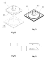
Fig. 39 is an exploded view of the installing structure of the suction disk according to the present application; -
Fig. 40 is a front view showing that the shape of the suction disk according to the present application is square; -
Fig. 41 is a left view ofFig. 40 ; -
Fig. 42 is a back view ofFig. 40 ; -
Fig. 43 is a bottom view ofFig. 40 ; -
Fig. 44 is a top view ofFig. 40 ; -
Fig. 45 is a sectional view along the direction L-L ofFig. 44 ; -
Fig. 46 is a sectional view along the direction M-M ofFig. 44 ; -
Fig. 47 is a front view showing the release state of the soft rubber suction disk when the shape of the suction disk according to the present application is square; -
Fig. 48 is a front view showing the relationship between the pushing switch and the pin shaft in the release state of the soft rubber suction disk when the shape of the suction disk according to the present application is square; -
Fig. 49 is a sectional view along the direction N-N ofFig. 48 ; -
Fig. 50 is a front view showing the adsorption state of the soft rubber suction disk when the shape of the suction disk according to the present application is square; -
Fig. 51 is a front view showing the relationship between the pushing switch and the pin shaft in the adsorption state of the soft rubber suction disk when the shape of the suction disk according to the present application is square; -
Fig. 52 is a sectional view along the direction O-O ofFig. 51 ; -
Fig. 53 is a front view of the pushing switch when the shape of the suction disk according to the present application is square; -
Fig. 54 is a left view ofFig. 53 ; -
Fig. 55 is a top view ofFig. 53 ; -
Fig. 56 is a sectional view along the direction P-P ofFig. 55 ; -
Fig. 57 is a bottom view ofFig. 53 ; -
Fig. 58 is a perspective view of the pushing switch when the shape of the suction disk according to the present application is square; -
Fig. 59 is a front view of the base when the shape of the suction disk according to the present application is square; -
Fig. 60 is a left view ofFig. 59 ; -
Fig. 60 is a top view ofFig. 59 ; -
Fig. 62 is a sectional view along the direction Q-Q ofFig. 61 ; -
Fig. 63 is a sectional view along the direction R-R ofFig. 61 ; -
Fig. 64 is a bottom view ofFig. 59 ; -
Fig. 65 is a perspective view of the base when the shape of the suction disk according to the present application is square; -
Fig. 66 is a front view of the soft rubber suction disk when the shape of the suction disk according to the present application is square; -
Fig. 67 is a left view ofFig. 66 ; -
Fig. 68 is a top view ofFig. 66 ; -
Fig. 69 is a sectional view along the direction S-S ofFig. 68 ; -
Fig. 70 is a sectional view along the direction T-T ofFig. 68 ; -
Fig. 71 is a bottom view ofFig. 66 ; -
Fig. 72 is an exploded view of the installing structure of the soft rubber suction disk when the shape of the suction disk according to the present application is square; -
Fig. 73 is a perspective view of the soft rubber suction disk when the shape of the suction disk according to the present application is square; -
Fig. 74 is a front view of the driving slide cover when the shape of the suction disk according to the present application is square; -
Fig. 75 is a left view ofFig. 74 ; -
Fig. 76 is a top view ofFig. 74 ; -
Fig. 77 is a sectional view along the direction U-U ofFig. 76 ; -
Fig. 78 is a sectional view along the direction V-V ofFig.76 ; -
Fig. 79 is a bottom view ofFig. 74 ; -
Fig. 80 is a perspective view of the driving slide cover when the shape of the suction disk according to the present application is square; -
Fig. 81 is a perspective view when the shape of the suction disk according to the present application is square; and -
Fig. 82 is an exploded view of the installing structure when the shape of the suction disk according to the present application is square. - In order that technical solutions according to the present application can be better understood by those skilled in the art, hereinafter, the technical solutions will be described in conjunction with embodiments.
- As shown in
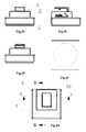
Figs.1 to 82 , a suction disk according to an embodiment of the present application includes: a softrubber suction disk 1 with adraw bar 11, abase 2 mounted on the back face of the softrubber suction disk 1, and areturn spring 3 located between the softrubber suction disk 1 and thebase 2. An end of thedraw bar 11 is provided with apin shaft 12 radially extended towards two sides of the draw bar. The suction disk further includes adriving device 4 for driving thedraw bar 11 to rise and fall by pushing thepin shaft 12. The center of thebase 2 has acentral guiding hole 21 for guiding thedraw bar 11 to move axially. A guidingcolumn 23 having symmetrical guidingplanes 22 at two sides of the guiding column and a pair of symmetrical position-limitingguiding flanges 24 are upwardly protruded around thecentral guiding hole 21, forming guidinggrooves 25 between the guidingplanes 22 and the position-limitingguiding flanges 24. The guidingcolumn 23 further has a pin shaft rise-fall guiding groove 26 that is perpendicular to thesymmetrical guiding planes 22 at two sides of the guiding column and extended along the axial direction. Two ends of thepin shaft 12 are hidden in the pin shaft rise-fall guiding groove 26. The drivingdevice 4 includes a pushingswitch 41 mounted on thebase 2 and a drivingslide cover 5 connected with the pushingswitch 41 and having a supporting member. The center of the pushingswitch 41 has an elongate guidinghole 42, and each of two symmetrical sides of the elongate guidinghole 42 is provided with aninclined step 43 with an upper end supporting surface and a lower end supporting surface. The pushingswitch 41 is sleeved on the guidingcolumn 23 through the elongate guidinghole 42 in a slidable cooperation manner such that the pushingswitch 41 is guided in the guidinggroove 25. Thedraw bar 11 is extended through thecentral guiding hole 21 of thebase 2 and the center of the pushingswitch 41 such that two ends of thepin shaft 12 are simultaneously hidden in the inclined steps 43. As the pushingswitch 41 is driven by the drivingslide cover 5 to slide back and forth in a radial direction, thepin shaft 12 is moved up and down along theinclined step 43 and can be stopped on the upper and lower end supporting surfaces of the inclined step, respectively, thereby driving thedraw bar 11 to rise and fall to drive the softrubber suction disk 1, to thereby achieving an adsorption state and a release state. - An
annular boss 15 for limiting the position of thereturn spring 3 is provided on the back surface of the softrubber suction disk 1 and is around thedraw bar 11. - A
notch 47 is formed on the side wall corresponded to the lower end supporting surface of theinclined step 43, to facilitate pushing thepin shaft 12 such that it is mounted in thecentral guiding hole 21. - The driving
slide cover 5 is provided with movement direction marks indicating the adsorption or release state, and the movement direction mark indicating the adsorption state is the same as the downwardly inclined direction of theinclined step 43, while the movement direction mark indicating the release state is opposite to the downwardly inclined direction of theinclined step 43. - In the present embodiment, the
pin shaft 12 may be implanted after an end of thedraw bar 11 is provided with a pin hole. Thedraw bar 11 may be a circular, square or polygon column, and the center of thebase 2 is formed with a corresponding square or polygoncentral guiding hole 21 to limit thedraw bar 11 such that it can only slide in the axial direction, which can reduce the failure caused by the rotation displacement of thedraw bar 11 in the process that thepin shaft 12 is moved up and down along theinclined step 43 by the radial back and forth movement of the pushingswitch 41. The pushing stroke of the pushingswitch 41 should meet the requirement of the movement stroke of thepin shaft 12 between the two ends of theinclined step 43. While heights of the two end supporting surfaces of theinclined step 43 and height difference between the two end supporting surfaces should simultaneously meet that the softrubber suction disk 1 has the largest adsorption force and thedraw bar 11 has the largest rise-fall stroke. The gentle theinclined step 43 is, the longer the stoke of the pushingswitch 41 is, and thus less effort is taken, however, thebase 2 would become larger. Therefore the inclination angle of theinclined step 43 should be suitably selected. Generally, it is preferable that the inclination angle is between 14 degree and 18 degree. The internal cavity of thebase 2 facing to the softrubber suction disk 1 may be configured into a horn-shaped conical surface which is corresponded to the shape of the back face of the softrubber suction disk 1 in the adsorption state, to support the back face of the softrubber suction disk 1 in the adsorption state, thereby stabilizing the fastness of the suction disk. - As shown in
Figs. 5-6 ,13-18 ,31-36 ,45-46 ,53-58 and74-79 , one of the preferred embodiments of the present application is that: the front and back ends of the bottom surface of the pushingswitch 41 are formed with thesame recess 44, the internal wall of each of the front and back bottom edges of the drivingslide cover 5 has aclasp 51, and the drivingslide cover 5 is connected with the pushingswitch 41 by the snap fit self-locking cooperation of theclasp 51 and therecess 44. In the present embodiment, theclasps 51 are a pair of L-shaped outward barbs, and the extending direction of therecess 44 is the same as the sliding directions of the drivingslide cover 5 and the pushingswitch 41, and it is preferable that the width of therecess 44 and the width of theclasp 51 are configured to be just suitable for the clasp to be hidden in the recess and play a position-limiting action, such that the drivingslide cover 5 and the pushingswitch 41 are firmly connected. Alternatively, the recess may be replaced by a notch. - As shown in
Figs. 16-18 and56-58 , a second preferred embodiment of the present application is that: in the upper and lower end supporting surfaces of theinclined step 43, the upperend supporting surface 45 is a concave surface, and the lowerend supporting surface 46 is a flat surface. In the present embodiment, the upperend supporting surface 45 is configured to be a concave surface such that thepin shaft 12 will not slip off when it is hidden in the concave surfaces, thereby maintaining a better adsorption force of the suction disk. - As shown in
Figs. 1-7 ,31-37 ,41-47 and74-80 , a third preferred embodiment of the present application is that: the supporting member of the drivingslide cover 5 is configured as a flatsquare hook 52 bent upwardly. In the present embodiment, the flatsquare hook 52 is an upward L-shaped hook, the flat square shape facilitates pushing the drivingslide cover 5, and it is more beautiful and generous. - As shown in
Figs. 66-73 , a fourth preferred embodiment of the present application is that: the softrubber suction disk 1 includes a drawingbottom disk 13 integrally connected with thedraw bar 11 and a silicagel suction cushion 14. The drawingbottom disk 13 is embedded in the silicagel suction cushion 14 to form a suction disk body. Through holes are formed on the circumferential edge of the drawingbottom disk 13, and the silicagel suction cushion 14 is passed through the through holes such that the circumferential edge of the drawingbottom disk 13 is embedded in the silica gel suction cushion. In the present embodiment, the drawingbottom disk 13 may be made of a plastic material; and thedraw bar 11 may be made of a metal or plastic material, and may be injection molded together with the drawingbottom disk 13, and then the silicagel suction cushion 14 is molded by casting such that the drawing bottom disk is embedded therein, forming a suction disk body, which makes the adsorption force of the suction disk more stable. - A fifth preferred embodiment of the present application is that: each of the soft
rubber suction disk 1, thebase 2, the pushingswitch 41 and the drivingslide cover 5 has a square or has a circular shape. In the present embodiment, as shown inFigs. 1-39 , each of the softrubber suction disk 1, thebase 2, the pushingswitch 41 and the drivingslide cover 5 has a circular shape. As shown inFigs. 40-82 , each of the softrubber suction disk 1, thebase 2, the pushingswitch 41 and the drivingslide cover 5 has a square shape. The above components may have an oval or a polygon shape, etc.. A suction disk having all of the above shapes can make a tidy, beautiful and generous installing environment. - In the present application, with an inclined step pushing type driving device, the pushing
switch 41 is driven to slide back and forth in the radial direction under the action of the drivingslide cover 5, it is easy for thepin shaft 12 at the end of thedraw bar 11 to be pushed up and down by theinclined steps 43 at the center of the suction disk, thepin shaft 12 is moved up and down along theinclined steps 43 and can be stopped on the upper and lower end supporting surfaces of the inclined steps, respectively. Thereby thedraw bar 11 is driven to rise and fall to drive the softrubber suction disk 1 to be in the adsorption state and the release state. It is easy to push the pushingswitch 41 to the end to be in the self-locking state. At the same time, thebase 2 may serve as not only a back support for the soft rubber suction disk but also a sliding seat for the pushingswitch 41. The base may also serve as a shell of the main body of the suction disk. The entire suction disk may have various shapes, for example, a square shape, a circular shape, an oval shape or a polygon shape. Thereby, with such a suction disk, the installation environment becomes tidy, beautiful and generous, the adsorption force is improved, the adsorption effect is stable, the hanging article will not be easily fall off, the operation is more simple and easier, and the structure is simple and beautiful. - The person skilled in the art can achieve or implement the present application based on the above description of the embodiments. It is apparent for the person skilled in the art to make many modifications to the embodiments. The general principle defined herein may be achieved in other embodiments without departing from the spirit or scope of the present application. Therefore, the present application is not limited to the embodiments illustrated herein, but should be defined by the broadest scope consistent with the principle and novel features disclosed herein.
Claims (10)
- A suction disk structure, comprising: a soft rubber suction disk (1) with a draw bar (11), a base (2) mounted on a back face of the soft rubber suction disk (1) and a return spring (3) located between the soft rubber suction disk (1) and the base (2), an end of the draw bar (11) is provided with a pin shaft (12) radially extended towards two sides of the draw bar (11), and the suction disk further comprises a driving device (4) for driving the draw bar (11) to rise and fall by pushing the pin shaft (12), wherein
a center of the base (2) has a central guiding hole (21) for guiding the draw bar (11) to move axially; a guiding column (23) having symmetrical guiding planes (22) at two sides of the guiding column and a pair of symmetrical position-limiting guiding flanges (24) are upwardly protruded around the central guiding hole (21), forming guiding grooves (25) between the guiding planes (22) and the position-limiting guiding flanges (24); the guiding column (23) further has a pin shaft rise-fall guiding groove (26) that is perpendicular to the symmetrical guiding planes (22) at two sides of the guiding column and extended along the axial direction, and two ends of the pin shaft (12) are hidden in the pin shaft rise-fall guiding groove (26);
the driving device (4) comprises a pushing switch (41) mounted on the base (2) and a driving slide cover (5) connected with the pushing switch (41) and having a supporting member; the center of the pushing switch (41) has an elongate guiding hole (42), and each of two symmetrical sides of the elongate guiding hole (42) is provided with an inclined step (43) with an upper end supporting surface and a lower end supporting surface; and the pushing switch (41) is sleeved on the guiding column (23) through the elongate guiding hole (42) in a slidable cooperation manner such that the pushing switch (41) is guided in the guiding groove (25); and
the draw bar (11) is extended through the central guiding hole (21) of the base (2) and a center of the pushing switch (41) such that two ends of the pin shaft (12) are simultaneously hidden in the inclined steps (43); as the pushing switch (41) is driven by the driving slide cover (5) to slide back and forth in a radial direction, the pin shaft (12) is moved up and down along the inclined step (43) and can be stopped on the upper and lower end supporting surfaces of the inclined step (43), respectively, thereby driving the draw bar (11) to rise and fall to drive the soft rubber suction disk (1), to thereby achieving an adsorption state and a release state. - The suction disk structure according to claim 1, wherein each of a front end and a back end of a bottom surface of the pushing switch (41) is formed with a recess (44), an internal wall of each of front and back bottom edges of the driving slide cover (5) is provided with a clasp (51), and the driving slide cover (5) is connected with the pushing switch (41) by self-locking snap fit of the clasp (51) and the recess (44).
- The suction disk structure according to claim 1, wherein in the upper and lower end supporting surfaces of the inclined step (43), the upper end supporting surface (45) is a concave surface, and the lower end supporting surface (46) is a flat surface.
- The suction disk structure according to claim 1, wherein the supporting member of the driving slide cover (5) is a flat square hook (52) bent upwardly.
- The suction disk structure according to claim 1, wherein the soft rubber suction disk (1) comprises a drawing bottom disk (13) integrally connected with the draw bar (11) and a silica gel suction cushion (14), and the drawing bottom disk (13) is embedded in the silica gel suction cushion (14) to form a suction disk body.
- The suction disk structure according to claim 5, wherein a through hole is formed on a circumferential edge of the drawing bottom disk (13), and the silica gel suction cushion (14) is passed through the through hole such that the circumferential edge of the drawing bottom disk (13) is embedded in the silica gel suction cushion.
- The suction disk structure according to claim 1, wherein each of the soft rubber suction disk (1), the base (2), the pushing switch (41) and the driving slide cover (5) has a square shape or has a circular shape.
- The suction disk structure according to claim 1, wherein an annular boss (15) for limiting a position of the return spring (3) is provided on a back surface of the soft rubber suction disk (1) and is around the draw bar (11).
- The suction disk structure according to claim 1, wherein the driving slide cover (5) is provided with movement direction marks indicating the adsorption or release state, and wherein the movement direction mark indicating the adsorption state is the same as the downwardly inclined direction of the inclined step (43), while the movement direction mark indicating the release state is opposite to the downwardly inclined direction of the inclined step (43).
- The suction disk structure according to claim 1, wherein a notch (47) is formed on a side wall corresponded to the lower end supporting surface (46) of the inclined step (43), to facilitate pushing the pushing pin shaft (12) such that it is mounted in the central guiding hole (21).
Priority Applications (1)
| Application Number | Priority Date | Filing Date | Title |
|---|---|---|---|
| PL13765275T PL2700830T3 (en) | 2012-06-15 | 2013-03-04 | Sucking structure |
Applications Claiming Priority (3)
| Application Number | Priority Date | Filing Date | Title |
|---|---|---|---|
| CN 201220285179 CN202756403U (en) | 2012-06-15 | 2012-06-15 | Sucking disc structure |
| CN201310044753.8A CN103256291B (en) | 2013-02-04 | 2013-02-04 | A kind of sucker structure |
| PCT/CN2013/072120 WO2013185493A1 (en) | 2012-06-15 | 2013-03-04 | Sucking structure |
Publications (3)
| Publication Number | Publication Date |
|---|---|
| EP2700830A1 true EP2700830A1 (en) | 2014-02-26 |
| EP2700830A4 EP2700830A4 (en) | 2014-08-06 |
| EP2700830B1 EP2700830B1 (en) | 2016-03-02 |
Family
ID=49757485
Family Applications (1)
| Application Number | Title | Priority Date | Filing Date |
|---|---|---|---|
| EP13765275.6A Active EP2700830B1 (en) | 2012-06-15 | 2013-03-04 | Sucking structure |
Country Status (16)
| Country | Link |
|---|---|
| US (1) | US9091294B2 (en) |
| EP (1) | EP2700830B1 (en) |
| JP (1) | JP5642906B2 (en) |
| KR (1) | KR101510363B1 (en) |
| AU (1) | AU2013224645B2 (en) |
| BR (1) | BR112014016669B1 (en) |
| CA (1) | CA2828164C (en) |
| CH (1) | CH708489B1 (en) |
| CL (1) | CL2014003109A1 (en) |
| ES (1) | ES2566138T3 (en) |
| IL (1) | IL235310B (en) |
| NO (1) | NO341428B1 (en) |
| PL (1) | PL2700830T3 (en) |
| RU (1) | RU2543459C1 (en) |
| WO (1) | WO2013185493A1 (en) |
| ZA (1) | ZA201407679B (en) |
Cited By (5)
| Publication number | Priority date | Publication date | Assignee | Title |
|---|---|---|---|---|
| EP2878836A1 (en) * | 2014-09-01 | 2015-06-03 | Cheng-Chien Hsu | Suction cup |
| CN105526235A (en) * | 2014-09-30 | 2016-04-27 | 富鼎电子科技(嘉善)有限公司 | Suction cup mechanism and taking and placing device comprising same |
| CN106640922A (en) * | 2016-08-30 | 2017-05-10 | 杨海波 | Hanging component |
| EP3382218A4 (en) * | 2015-11-26 | 2019-07-10 | Anho Houseware Co., Ltd. Jiangmen | VACUUM AND VACUUM SUCTION COMPRISING |
| CN112660731A (en) * | 2020-04-15 | 2021-04-16 | 盐城佳华塑料制品有限公司 | Artificial intelligence handling device that stationarity is high |
Families Citing this family (13)
| Publication number | Priority date | Publication date | Assignee | Title |
|---|---|---|---|---|
| AU354316S (en) * | 2013-01-30 | 2014-03-17 | Anho Houseware Co | Square-shaped suction cup |
| US20150369276A1 (en) * | 2014-06-23 | 2015-12-24 | Daymen Us, Inc. | High Stiffness Suction Cup Device |
| AU357784S (en) * | 2014-07-26 | 2014-09-25 | Anho Houseware Co | Square-shaped suction cup |
| USD756754S1 (en) * | 2014-09-17 | 2016-05-24 | Beaconmedaes Llc | Hook plate |
| JP6489575B2 (en) * | 2014-09-25 | 2019-03-27 | 株式会社貝印刃物開発センター | Suction cup device |
| US10435173B2 (en) * | 2017-01-16 | 2019-10-08 | The Boeing Company | Remote optical control surface indication system |
| CN106763105A (en) * | 2017-01-17 | 2017-05-31 | 宁波市峰铭日用品制造有限公司 | A kind of vacuum cup |
| US10610062B2 (en) * | 2018-08-31 | 2020-04-07 | Jeffery Alan Mieldon | Washcloth identification system |
| CN109147567A (en) * | 2018-11-07 | 2019-01-04 | 深圳市中银科技有限公司 | A kind of anti-down vertical advertising machine |
| CN110742429B (en) * | 2019-10-12 | 2022-10-18 | 上海慧晗实业有限公司 | Intelligence sucking disc folding chair |
| CN116174928B (en) * | 2022-12-12 | 2025-12-30 | 苏州德龙激光股份有限公司 | An automated FPC cutting and waste removal device |
| KR200499362Y1 (en) * | 2023-11-28 | 2025-07-11 | 팬 이글 | Multiple adsorption fixed device |
| CN119786379B (en) * | 2024-11-29 | 2025-08-22 | 浙江东瓷科技有限公司 | A laminating device for packaging shell base deformation consistency |
Family Cites Families (25)
| Publication number | Priority date | Publication date | Assignee | Title |
|---|---|---|---|---|
| JPS4830777Y1 (en) * | 1969-10-20 | 1973-09-19 | ||
| SU735837A1 (en) | 1978-07-04 | 1980-05-25 | За витель . -- « -лчад ;°;Т ннчйё ш| 735837 04 | Suction devivce |
| US5104077A (en) * | 1990-09-07 | 1992-04-14 | Hung Mei Brush Co., Ltd. | Suction cup |
| RU2105908C1 (en) * | 1995-05-23 | 1998-02-27 | Московское авиационное производственное объединение "МИГ" (государственное предприятие) | Hold-down used in bonding parts |
| GB2330363B (en) * | 1997-10-16 | 2002-03-27 | Michael Ritson | Portable wringer |
| CN1417495A (en) * | 2001-11-08 | 2003-05-14 | 邹德骏 | Fast linked suction cup seat |
| US6666420B1 (en) | 2003-02-25 | 2003-12-23 | Jeffrey D. Carnevali | Suction cup having compact axial installation and release mechanism |
| US7607622B2 (en) | 2006-03-08 | 2009-10-27 | Carnevali Jeffrey D | Suction cup having compact axial installation and release mechanism |
| KR200420964Y1 (en) | 2006-04-24 | 2006-07-07 | 우철석 | Multipurpose Vacuum Adsorption Apparatus |
| FR2902474A3 (en) | 2006-06-20 | 2007-12-21 | Northstar Systems Corp | Suction disc forming device for fixing e.g. cellular phone, on smooth surface, has rod including rectangular slot hole, and control element pivoted with projecting part of body via pivot shaft that passes through hole |
| US7455269B1 (en) * | 2007-07-09 | 2008-11-25 | Li-Sheng Chien | Suction device |
| KR20090017950A (en) | 2007-08-16 | 2009-02-19 | (주)용성엔지니어링 | Vacuum adsorber |
| CN201125930Y (en) * | 2007-12-12 | 2008-10-01 | 深圳市泉春达电子制品厂 | Sucking disc |
| CN101265939A (en) * | 2008-04-28 | 2008-09-17 | 中国第十七冶金建设有限公司 | Multifunctional suction disc equipment |
| KR20100108176A (en) * | 2009-03-27 | 2010-10-06 | 최민우 | Onetouch suction |
| TWI403646B (en) | 2009-04-02 | 2013-08-01 | Primax Electronics Ltd | Suction cup assembly and fastening device including the same |
| KR20110020955A (en) | 2009-08-24 | 2011-03-04 | (주)굿센스 | Springy vacuum fixer |
| TWM387925U (en) | 2010-02-26 | 2010-09-01 | Wistron Neweb Corp | Suction device |
| JP3163069U (en) * | 2010-07-05 | 2010-09-30 | 鐵▲たん▼企業有限公司 | Suction cup structure |
| CN101881367B (en) | 2010-07-13 | 2013-05-22 | 广东铁将军防盗设备有限公司 | scaffold coordination structure |
| CN201802741U (en) * | 2010-10-05 | 2011-04-20 | 高德海 | Strong sucker |
| CN102072242A (en) * | 2011-01-11 | 2011-05-25 | 洪振斌 | Vacuum seal sucking disk |
| WO2012163411A1 (en) * | 2011-05-31 | 2012-12-06 | Valeo Schalter Und Sensoren Gmbh | A holding means for an electronic device |
| CN202203267U (en) * | 2011-09-15 | 2012-04-25 | 上海松越贸易有限公司 | Multipurpose sucker type pendant |
| CN202756403U (en) * | 2012-06-15 | 2013-02-27 | 江门市安豪贸易有限公司 | Sucking disc structure |
-
2013
- 2013-03-04 ES ES13765275.6T patent/ES2566138T3/en active Active
- 2013-03-04 WO PCT/CN2013/072120 patent/WO2013185493A1/en not_active Ceased
- 2013-03-04 EP EP13765275.6A patent/EP2700830B1/en active Active
- 2013-03-04 US US14/007,964 patent/US9091294B2/en active Active
- 2013-03-04 JP JP2014520531A patent/JP5642906B2/en active Active
- 2013-03-04 PL PL13765275T patent/PL2700830T3/en unknown
- 2013-03-04 BR BR112014016669-2A patent/BR112014016669B1/en active IP Right Grant
- 2013-03-04 RU RU2013145506/12A patent/RU2543459C1/en active
- 2013-03-04 CH CH01677/14A patent/CH708489B1/en unknown
- 2013-03-04 CA CA2828164A patent/CA2828164C/en active Active
- 2013-03-04 KR KR1020137025812A patent/KR101510363B1/en active Active
- 2013-03-04 AU AU2013224645A patent/AU2013224645B2/en not_active Ceased
-
2014
- 2014-10-22 ZA ZA2014/07679A patent/ZA201407679B/en unknown
- 2014-10-23 IL IL235310A patent/IL235310B/en active IP Right Grant
- 2014-11-14 NO NO20141368A patent/NO341428B1/en unknown
- 2014-11-14 CL CL2014003109A patent/CL2014003109A1/en unknown
Cited By (6)
| Publication number | Priority date | Publication date | Assignee | Title |
|---|---|---|---|---|
| EP2878836A1 (en) * | 2014-09-01 | 2015-06-03 | Cheng-Chien Hsu | Suction cup |
| CN105526235A (en) * | 2014-09-30 | 2016-04-27 | 富鼎电子科技(嘉善)有限公司 | Suction cup mechanism and taking and placing device comprising same |
| CN105526235B (en) * | 2014-09-30 | 2018-12-21 | 富鼎电子科技(嘉善)有限公司 | Sucking disc mechanism and fetching device with the sucking disc mechanism |
| EP3382218A4 (en) * | 2015-11-26 | 2019-07-10 | Anho Houseware Co., Ltd. Jiangmen | VACUUM AND VACUUM SUCTION COMPRISING |
| CN106640922A (en) * | 2016-08-30 | 2017-05-10 | 杨海波 | Hanging component |
| CN112660731A (en) * | 2020-04-15 | 2021-04-16 | 盐城佳华塑料制品有限公司 | Artificial intelligence handling device that stationarity is high |
Also Published As
| Publication number | Publication date |
|---|---|
| PL2700830T3 (en) | 2016-07-29 |
| RU2543459C1 (en) | 2015-02-27 |
| CH708489B1 (en) | 2016-10-31 |
| US9091294B2 (en) | 2015-07-28 |
| NO341428B1 (en) | 2017-11-13 |
| CA2828164A1 (en) | 2013-12-15 |
| BR112014016669B1 (en) | 2020-11-17 |
| AU2013224645B2 (en) | 2015-07-16 |
| NO20141368A1 (en) | 2014-12-11 |
| BR112014016669A2 (en) | 2017-06-27 |
| EP2700830A4 (en) | 2014-08-06 |
| IL235310B (en) | 2018-07-31 |
| JP2014522470A (en) | 2014-09-04 |
| ES2566138T3 (en) | 2016-04-11 |
| CL2014003109A1 (en) | 2015-01-16 |
| JP5642906B2 (en) | 2014-12-17 |
| AU2013224645A1 (en) | 2014-01-16 |
| EP2700830B1 (en) | 2016-03-02 |
| WO2013185493A1 (en) | 2013-12-19 |
| ZA201407679B (en) | 2016-10-26 |
| CA2828164C (en) | 2016-06-28 |
| US20140306083A1 (en) | 2014-10-16 |
| KR101510363B1 (en) | 2015-04-14 |
| KR20140047035A (en) | 2014-04-21 |
Similar Documents
| Publication | Publication Date | Title |
|---|---|---|
| AU2013224645B2 (en) | Suction disk structure | |
| AU2013383535B2 (en) | Vacuum absorber | |
| US9220372B2 (en) | Glass bowl assembly for bowl lift mixer | |
| CN214274214U (en) | Structure of suction cup | |
| WO2015200309A2 (en) | High stiffness suction cup device | |
| CN202756403U (en) | Sucking disc structure | |
| CN103256291B (en) | A kind of sucker structure | |
| CN218528423U (en) | Suction cup type hook | |
| CN212267127U (en) | Wheel decorative cover with decorative supporting angle | |
| CN204555102U (en) | Air-conditioner outdoor unit and handle installing structure thereof | |
| CN209621814U (en) | A kind of front cabin cover plate installation buckle | |
| CN207814203U (en) | A sucker device | |
| CN208875072U (en) | A kind of drawer-type structure for pet nest | |
| CN222303809U (en) | Bottle hanging bracket | |
| CN222122011U (en) | Suction cup device and suction cup hook | |
| CN215127030U (en) | Sucker rod hanging device | |
| CN222502382U (en) | Suction cup device and hook with suction cup device | |
| CN205493752U (en) | A dish washer that is used for saucer of dish washer and has it | |
| CN219932700U (en) | Easy-to-detach sucker fixing piece | |
| CN221180098U (en) | Detachable hanging decoration connecting structure | |
| CN217626948U (en) | Supporting structure and plastic wrap cutterbar | |
| CN112971486B (en) | Quilt fixer | |
| USD899265S1 (en) | Vial | |
| CN206525995U (en) | Main suction pipe assembly | |
| JP2009273525A (en) | Curtain suspender |
Legal Events
| Date | Code | Title | Description |
|---|---|---|---|
| PUAI | Public reference made under article 153(3) epc to a published international application that has entered the european phase |
Free format text: ORIGINAL CODE: 0009012 |
|
| 17P | Request for examination filed |
Effective date: 20130927 |
|
| AK | Designated contracting states |
Kind code of ref document: A1 Designated state(s): AL AT BE BG CH CY CZ DE DK EE ES FI FR GB GR HR HU IE IS IT LI LT LU LV MC MK MT NL NO PL PT RO RS SE SI SK SM TR |
|
| A4 | Supplementary search report drawn up and despatched |
Effective date: 20140703 |
|
| RIC1 | Information provided on ipc code assigned before grant |
Ipc: F16B 47/00 20060101AFI20140629BHEP Ipc: A47G 29/087 20060101ALI20140629BHEP |
|
| GRAP | Despatch of communication of intention to grant a patent |
Free format text: ORIGINAL CODE: EPIDOSNIGR1 |
|
| DAX | Request for extension of the european patent (deleted) | ||
| INTG | Intention to grant announced |
Effective date: 20150825 |
|
| GRAS | Grant fee paid |
Free format text: ORIGINAL CODE: EPIDOSNIGR3 |
|
| RIN1 | Information on inventor provided before grant (corrected) |
Inventor name: ZHANG, DECAI |
|
| RAP1 | Party data changed (applicant data changed or rights of an application transferred) |
Owner name: ANHO HOUSEWARE CO., LTD. JIANGMEN |
|
| GRAA | (expected) grant |
Free format text: ORIGINAL CODE: 0009210 |
|
| AK | Designated contracting states |
Kind code of ref document: B1 Designated state(s): AL AT BE BG CH CY CZ DE DK EE ES FI FR GB GR HR HU IE IS IT LI LT LU LV MC MK MT NL NO PL PT RO RS SE SI SK SM TR |
|
| REG | Reference to a national code |
Ref country code: GB Ref legal event code: FG4D |
|
| REG | Reference to a national code |
Ref country code: FR Ref legal event code: PLFP Year of fee payment: 4 |
|
| REG | Reference to a national code |
Ref country code: AT Ref legal event code: REF Ref document number: 778262 Country of ref document: AT Kind code of ref document: T Effective date: 20160315 Ref country code: CH Ref legal event code: EP Ref country code: CH Ref legal event code: NV Representative=s name: ISLER AND PEDRAZZINI AG, CH |
|
| REG | Reference to a national code |
Ref country code: IE Ref legal event code: FG4D |
|
| REG | Reference to a national code |
Ref country code: ES Ref legal event code: FG2A Ref document number: 2566138 Country of ref document: ES Kind code of ref document: T3 Effective date: 20160411 |
|
| REG | Reference to a national code |
Ref country code: DE Ref legal event code: R096 Ref document number: 602013005291 Country of ref document: DE |
|
| REG | Reference to a national code |
Ref country code: NL Ref legal event code: MP Effective date: 20160302 |
|
| REG | Reference to a national code |
Ref country code: LT Ref legal event code: MG4D |
|
| REG | Reference to a national code |
Ref country code: AT Ref legal event code: MK05 Ref document number: 778262 Country of ref document: AT Kind code of ref document: T Effective date: 20160302 |
|
| REG | Reference to a national code |
Ref country code: NO Ref legal event code: T2 Effective date: 20160302 |
|
| PG25 | Lapsed in a contracting state [announced via postgrant information from national office to epo] |
Ref country code: GR Free format text: LAPSE BECAUSE OF FAILURE TO SUBMIT A TRANSLATION OF THE DESCRIPTION OR TO PAY THE FEE WITHIN THE PRESCRIBED TIME-LIMIT Effective date: 20160603 Ref country code: HR Free format text: LAPSE BECAUSE OF FAILURE TO SUBMIT A TRANSLATION OF THE DESCRIPTION OR TO PAY THE FEE WITHIN THE PRESCRIBED TIME-LIMIT Effective date: 20160302 |
|
| PG25 | Lapsed in a contracting state [announced via postgrant information from national office to epo] |
Ref country code: LT Free format text: LAPSE BECAUSE OF FAILURE TO SUBMIT A TRANSLATION OF THE DESCRIPTION OR TO PAY THE FEE WITHIN THE PRESCRIBED TIME-LIMIT Effective date: 20160302 Ref country code: LV Free format text: LAPSE BECAUSE OF FAILURE TO SUBMIT A TRANSLATION OF THE DESCRIPTION OR TO PAY THE FEE WITHIN THE PRESCRIBED TIME-LIMIT Effective date: 20160302 Ref country code: SE Free format text: LAPSE BECAUSE OF FAILURE TO SUBMIT A TRANSLATION OF THE DESCRIPTION OR TO PAY THE FEE WITHIN THE PRESCRIBED TIME-LIMIT Effective date: 20160302 Ref country code: AT Free format text: LAPSE BECAUSE OF FAILURE TO SUBMIT A TRANSLATION OF THE DESCRIPTION OR TO PAY THE FEE WITHIN THE PRESCRIBED TIME-LIMIT Effective date: 20160302 Ref country code: NL Free format text: LAPSE BECAUSE OF FAILURE TO SUBMIT A TRANSLATION OF THE DESCRIPTION OR TO PAY THE FEE WITHIN THE PRESCRIBED TIME-LIMIT Effective date: 20160302 Ref country code: BE Free format text: LAPSE BECAUSE OF NON-PAYMENT OF DUE FEES Effective date: 20160331 Ref country code: RS Free format text: LAPSE BECAUSE OF FAILURE TO SUBMIT A TRANSLATION OF THE DESCRIPTION OR TO PAY THE FEE WITHIN THE PRESCRIBED TIME-LIMIT Effective date: 20160302 |
|
| PG25 | Lapsed in a contracting state [announced via postgrant information from national office to epo] |
Ref country code: EE Free format text: LAPSE BECAUSE OF FAILURE TO SUBMIT A TRANSLATION OF THE DESCRIPTION OR TO PAY THE FEE WITHIN THE PRESCRIBED TIME-LIMIT Effective date: 20160302 Ref country code: IS Free format text: LAPSE BECAUSE OF FAILURE TO SUBMIT A TRANSLATION OF THE DESCRIPTION OR TO PAY THE FEE WITHIN THE PRESCRIBED TIME-LIMIT Effective date: 20160702 |
|
| PG25 | Lapsed in a contracting state [announced via postgrant information from national office to epo] |
Ref country code: CZ Free format text: LAPSE BECAUSE OF FAILURE TO SUBMIT A TRANSLATION OF THE DESCRIPTION OR TO PAY THE FEE WITHIN THE PRESCRIBED TIME-LIMIT Effective date: 20160302 Ref country code: SM Free format text: LAPSE BECAUSE OF FAILURE TO SUBMIT A TRANSLATION OF THE DESCRIPTION OR TO PAY THE FEE WITHIN THE PRESCRIBED TIME-LIMIT Effective date: 20160302 Ref country code: RO Free format text: LAPSE BECAUSE OF FAILURE TO SUBMIT A TRANSLATION OF THE DESCRIPTION OR TO PAY THE FEE WITHIN THE PRESCRIBED TIME-LIMIT Effective date: 20160302 Ref country code: SK Free format text: LAPSE BECAUSE OF FAILURE TO SUBMIT A TRANSLATION OF THE DESCRIPTION OR TO PAY THE FEE WITHIN THE PRESCRIBED TIME-LIMIT Effective date: 20160302 Ref country code: PT Free format text: LAPSE BECAUSE OF FAILURE TO SUBMIT A TRANSLATION OF THE DESCRIPTION OR TO PAY THE FEE WITHIN THE PRESCRIBED TIME-LIMIT Effective date: 20160704 |
|
| REG | Reference to a national code |
Ref country code: DE Ref legal event code: R097 Ref document number: 602013005291 Country of ref document: DE |
|
| REG | Reference to a national code |
Ref country code: IE Ref legal event code: MM4A |
|
| PG25 | Lapsed in a contracting state [announced via postgrant information from national office to epo] |
Ref country code: BE Free format text: LAPSE BECAUSE OF FAILURE TO SUBMIT A TRANSLATION OF THE DESCRIPTION OR TO PAY THE FEE WITHIN THE PRESCRIBED TIME-LIMIT Effective date: 20160302 |
|
| PLBE | No opposition filed within time limit |
Free format text: ORIGINAL CODE: 0009261 |
|
| STAA | Information on the status of an ep patent application or granted ep patent |
Free format text: STATUS: NO OPPOSITION FILED WITHIN TIME LIMIT |
|
| PG25 | Lapsed in a contracting state [announced via postgrant information from national office to epo] |
Ref country code: DK Free format text: LAPSE BECAUSE OF FAILURE TO SUBMIT A TRANSLATION OF THE DESCRIPTION OR TO PAY THE FEE WITHIN THE PRESCRIBED TIME-LIMIT Effective date: 20160302 Ref country code: IE Free format text: LAPSE BECAUSE OF NON-PAYMENT OF DUE FEES Effective date: 20160304 |
|
| 26N | No opposition filed |
Effective date: 20161205 |
|
| PG25 | Lapsed in a contracting state [announced via postgrant information from national office to epo] |
Ref country code: BG Free format text: LAPSE BECAUSE OF FAILURE TO SUBMIT A TRANSLATION OF THE DESCRIPTION OR TO PAY THE FEE WITHIN THE PRESCRIBED TIME-LIMIT Effective date: 20160602 Ref country code: SI Free format text: LAPSE BECAUSE OF FAILURE TO SUBMIT A TRANSLATION OF THE DESCRIPTION OR TO PAY THE FEE WITHIN THE PRESCRIBED TIME-LIMIT Effective date: 20160302 |
|
| REG | Reference to a national code |
Ref country code: FR Ref legal event code: PLFP Year of fee payment: 5 |
|
| PG25 | Lapsed in a contracting state [announced via postgrant information from national office to epo] |
Ref country code: MT Free format text: LAPSE BECAUSE OF FAILURE TO SUBMIT A TRANSLATION OF THE DESCRIPTION OR TO PAY THE FEE WITHIN THE PRESCRIBED TIME-LIMIT Effective date: 20160302 |
|
| REG | Reference to a national code |
Ref country code: FR Ref legal event code: PLFP Year of fee payment: 6 |
|
| PG25 | Lapsed in a contracting state [announced via postgrant information from national office to epo] |
Ref country code: HU Free format text: LAPSE BECAUSE OF FAILURE TO SUBMIT A TRANSLATION OF THE DESCRIPTION OR TO PAY THE FEE WITHIN THE PRESCRIBED TIME-LIMIT; INVALID AB INITIO Effective date: 20130304 Ref country code: CY Free format text: LAPSE BECAUSE OF FAILURE TO SUBMIT A TRANSLATION OF THE DESCRIPTION OR TO PAY THE FEE WITHIN THE PRESCRIBED TIME-LIMIT Effective date: 20160302 |
|
| PG25 | Lapsed in a contracting state [announced via postgrant information from national office to epo] |
Ref country code: MC Free format text: LAPSE BECAUSE OF FAILURE TO SUBMIT A TRANSLATION OF THE DESCRIPTION OR TO PAY THE FEE WITHIN THE PRESCRIBED TIME-LIMIT Effective date: 20160302 Ref country code: MT Free format text: LAPSE BECAUSE OF FAILURE TO SUBMIT A TRANSLATION OF THE DESCRIPTION OR TO PAY THE FEE WITHIN THE PRESCRIBED TIME-LIMIT Effective date: 20160331 Ref country code: MK Free format text: LAPSE BECAUSE OF FAILURE TO SUBMIT A TRANSLATION OF THE DESCRIPTION OR TO PAY THE FEE WITHIN THE PRESCRIBED TIME-LIMIT Effective date: 20160302 Ref country code: LU Free format text: LAPSE BECAUSE OF NON-PAYMENT OF DUE FEES Effective date: 20160304 |
|
| PG25 | Lapsed in a contracting state [announced via postgrant information from national office to epo] |
Ref country code: AL Free format text: LAPSE BECAUSE OF FAILURE TO SUBMIT A TRANSLATION OF THE DESCRIPTION OR TO PAY THE FEE WITHIN THE PRESCRIBED TIME-LIMIT Effective date: 20160302 |
|
| PGFP | Annual fee paid to national office [announced via postgrant information from national office to epo] |
Ref country code: PL Payment date: 20230328 Year of fee payment: 11 |
|
| PGFP | Annual fee paid to national office [announced via postgrant information from national office to epo] |
Ref country code: DE Payment date: 20240403 Year of fee payment: 12 |
|
| PGFP | Annual fee paid to national office [announced via postgrant information from national office to epo] |
Ref country code: FI Payment date: 20250321 Year of fee payment: 13 |
|
| PGFP | Annual fee paid to national office [announced via postgrant information from national office to epo] |
Ref country code: NO Payment date: 20250324 Year of fee payment: 13 |
|
| PGFP | Annual fee paid to national office [announced via postgrant information from national office to epo] |
Ref country code: GB Payment date: 20250317 Year of fee payment: 13 |
|
| PGFP | Annual fee paid to national office [announced via postgrant information from national office to epo] |
Ref country code: ES Payment date: 20250502 Year of fee payment: 13 |
|
| PGFP | Annual fee paid to national office [announced via postgrant information from national office to epo] |
Ref country code: IT Payment date: 20250321 Year of fee payment: 13 |
|
| PGFP | Annual fee paid to national office [announced via postgrant information from national office to epo] |
Ref country code: FR Payment date: 20250428 Year of fee payment: 13 |
|
| PGFP | Annual fee paid to national office [announced via postgrant information from national office to epo] |
Ref country code: CH Payment date: 20250401 Year of fee payment: 13 |
|
| PGFP | Annual fee paid to national office [announced via postgrant information from national office to epo] |
Ref country code: TR Payment date: 20250416 Year of fee payment: 13 |
|
| REG | Reference to a national code |
Ref country code: DE Ref legal event code: R119 Ref document number: 602013005291 Country of ref document: DE |
|
| PG25 | Lapsed in a contracting state [announced via postgrant information from national office to epo] |
Ref country code: DE Free format text: LAPSE BECAUSE OF NON-PAYMENT OF DUE FEES Effective date: 20251001 |
|
| REG | Reference to a national code |
Ref country code: CH Ref legal event code: U11 Free format text: ST27 STATUS EVENT CODE: U-0-0-U10-U11 (AS PROVIDED BY THE NATIONAL OFFICE) Effective date: 20260401 |