EP2700586A1 - Reagent container - Google Patents
Reagent container Download PDFInfo
- Publication number
- EP2700586A1 EP2700586A1 EP12773868.0A EP12773868A EP2700586A1 EP 2700586 A1 EP2700586 A1 EP 2700586A1 EP 12773868 A EP12773868 A EP 12773868A EP 2700586 A1 EP2700586 A1 EP 2700586A1
- Authority
- EP
- European Patent Office
- Prior art keywords
- band
- container body
- reagent
- reagent container
- container according
- Prior art date
- Legal status (The legal status is an assumption and is not a legal conclusion. Google has not performed a legal analysis and makes no representation as to the accuracy of the status listed.)
- Granted
Links
- 239000003153 chemical reaction reagent Substances 0.000 title claims abstract description 145
- 230000001681 protective effect Effects 0.000 claims abstract description 89
- 239000007788 liquid Substances 0.000 claims abstract description 27
- 239000000463 material Substances 0.000 claims description 34
- 239000003085 diluting agent Substances 0.000 claims description 14
- 210000000601 blood cell Anatomy 0.000 claims description 12
- 229920005989 resin Polymers 0.000 claims description 10
- 239000011347 resin Substances 0.000 claims description 10
- 210000002700 urine Anatomy 0.000 claims description 8
- 239000000853 adhesive Substances 0.000 claims description 7
- 230000001070 adhesive effect Effects 0.000 claims description 7
- 239000003599 detergent Substances 0.000 claims description 7
- 238000005187 foaming Methods 0.000 claims description 6
- 230000004048 modification Effects 0.000 description 10
- 238000012986 modification Methods 0.000 description 10
- -1 polyethylene Polymers 0.000 description 9
- 239000004698 Polyethylene Substances 0.000 description 8
- 229920000573 polyethylene Polymers 0.000 description 8
- 239000002131 composite material Substances 0.000 description 5
- 230000032258 transport Effects 0.000 description 5
- 238000004458 analytical method Methods 0.000 description 4
- 238000000034 method Methods 0.000 description 4
- 210000004027 cell Anatomy 0.000 description 3
- 239000006185 dispersion Substances 0.000 description 3
- 229920005673 polypropylene based resin Polymers 0.000 description 3
- 230000004888 barrier function Effects 0.000 description 2
- 230000007423 decrease Effects 0.000 description 2
- 230000035939 shock Effects 0.000 description 2
- 229920003002 synthetic resin Polymers 0.000 description 2
- 239000000057 synthetic resin Substances 0.000 description 2
- 239000004743 Polypropylene Substances 0.000 description 1
- 238000004140 cleaning Methods 0.000 description 1
- 230000008602 contraction Effects 0.000 description 1
- 238000010586 diagram Methods 0.000 description 1
- 230000000694 effects Effects 0.000 description 1
- 238000000684 flow cytometry Methods 0.000 description 1
- 239000012530 fluid Substances 0.000 description 1
- 238000007689 inspection Methods 0.000 description 1
- 238000005259 measurement Methods 0.000 description 1
- 229920001155 polypropylene Polymers 0.000 description 1
- 238000009877 rendering Methods 0.000 description 1
Images




Classifications
-
- B—PERFORMING OPERATIONS; TRANSPORTING
- B65—CONVEYING; PACKING; STORING; HANDLING THIN OR FILAMENTARY MATERIAL
- B65D—CONTAINERS FOR STORAGE OR TRANSPORT OF ARTICLES OR MATERIALS, e.g. BAGS, BARRELS, BOTTLES, BOXES, CANS, CARTONS, CRATES, DRUMS, JARS, TANKS, HOPPERS, FORWARDING CONTAINERS; ACCESSORIES, CLOSURES, OR FITTINGS THEREFOR; PACKAGING ELEMENTS; PACKAGES
- B65D5/00—Rigid or semi-rigid containers of polygonal cross-section, e.g. boxes, cartons or trays, formed by folding or erecting one or more blanks made of paper
- B65D5/02—Rigid or semi-rigid containers of polygonal cross-section, e.g. boxes, cartons or trays, formed by folding or erecting one or more blanks made of paper by folding or erecting a single blank to form a tubular body with or without subsequent folding operations, or the addition of separate elements, to close the ends of the body
- B65D5/06—Rigid or semi-rigid containers of polygonal cross-section, e.g. boxes, cartons or trays, formed by folding or erecting one or more blanks made of paper by folding or erecting a single blank to form a tubular body with or without subsequent folding operations, or the addition of separate elements, to close the ends of the body with end-closing or contents-supporting elements formed by folding inwardly a wall extending from, and continuously around, an end of the tubular body
- B65D5/064—Rectangular containers having a body with gusset-flaps folded outwardly or adhered to the side or the top of the container
-
- B—PERFORMING OPERATIONS; TRANSPORTING
- B01—PHYSICAL OR CHEMICAL PROCESSES OR APPARATUS IN GENERAL
- B01L—CHEMICAL OR PHYSICAL LABORATORY APPARATUS FOR GENERAL USE
- B01L3/00—Containers or dishes for laboratory use, e.g. laboratory glassware; Droppers
- B01L3/52—Containers specially adapted for storing or dispensing a reagent
-
- B—PERFORMING OPERATIONS; TRANSPORTING
- B65—CONVEYING; PACKING; STORING; HANDLING THIN OR FILAMENTARY MATERIAL
- B65D—CONTAINERS FOR STORAGE OR TRANSPORT OF ARTICLES OR MATERIALS, e.g. BAGS, BARRELS, BOTTLES, BOXES, CANS, CARTONS, CRATES, DRUMS, JARS, TANKS, HOPPERS, FORWARDING CONTAINERS; ACCESSORIES, CLOSURES, OR FITTINGS THEREFOR; PACKAGING ELEMENTS; PACKAGES
- B65D5/00—Rigid or semi-rigid containers of polygonal cross-section, e.g. boxes, cartons or trays, formed by folding or erecting one or more blanks made of paper
- B65D5/42—Details of containers or of foldable or erectable container blanks
- B65D5/44—Integral, inserted or attached portions forming internal or external fittings
- B65D5/46—Handles
- B65D5/46008—Handles formed separately from the container body
- B65D5/46016—Straps used as handles fixed to the container by glueing, stapling, heat-sealing
-
- B—PERFORMING OPERATIONS; TRANSPORTING
- B65—CONVEYING; PACKING; STORING; HANDLING THIN OR FILAMENTARY MATERIAL
- B65D—CONTAINERS FOR STORAGE OR TRANSPORT OF ARTICLES OR MATERIALS, e.g. BAGS, BARRELS, BOTTLES, BOXES, CANS, CARTONS, CRATES, DRUMS, JARS, TANKS, HOPPERS, FORWARDING CONTAINERS; ACCESSORIES, CLOSURES, OR FITTINGS THEREFOR; PACKAGING ELEMENTS; PACKAGES
- B65D5/00—Rigid or semi-rigid containers of polygonal cross-section, e.g. boxes, cartons or trays, formed by folding or erecting one or more blanks made of paper
- B65D5/42—Details of containers or of foldable or erectable container blanks
- B65D5/72—Contents-dispensing means
- B65D5/74—Spouts
- B65D5/746—Spouts formed separately from the container
Definitions
- the present invention relates to a reagent container, and more particularly, it relates to a reagent container for storing a liquid reagent employed for an analyzer.
- liquid reagents are used in an analyzer.
- Such a container enlarges both in weight and volume, and hence handling such as transportation has been inconvenient.
- a container described in Japanese Patent Laid-Open No. 6-345077 is known as a technique of improving handling of such a large-sized liquid container.
- a container having a tapelike handle is disclosed in the aforementioned Japanese Patent Laid-Open No. 6-345077 .
- This container has a rectangular parallelepiped shape, and has a volume of at least 3 to 5 liters.
- the tapelike handle is made of synthetic resin, and both ends of the tapelike handle are stuck to portions close to upper end portions of a pair of opposed side surfaces of the container.
- the tapelike handle is provided to extend over the upper surface of the container, and it is possible for the user to carry the reagent container in a suspending manner by grasping the handle.
- Patent Document 1 Japanese Patent Laid-Open No. 6-345077
- the present invention has been proposed in order to solve the aforementioned problem, and one object of the present invention is to provide a reagent container easily transportable also in a case where the same is heavy with a large content weight.
- a reagent container includes a container body for storing a liquid reagent employed for an analyzer and a band-like grasp portion mounted on the container body so that the user grasps the container body in a suspended state, while the grasp portion includes a band-like member whose first and second end sides are mounted on the container body and a protective member provided on the band-like member to project from an edge portion of the band-like member.
- the grasp portion is provided with the band-like member whose first and second end sides are mounted on the container body and the protective member provided on the band-like member to project from the edge portion of the band-like member so that the user can transport the reagent container by grasping both of the band-like member and the protective member, whereby biting of the grasp portion into fingers of the user is suppressed by the protective member and the user can be inhibited from feeling a pain.
- the protective member projects from the edge portion of the band-like member, whereby the protective member can be reliably interposed between the edge portion of the band-like member and the fingers of the user.
- the edge portion of the band-like member can be inhibited from hurting the fingers of the user.
- the reagent container can be easily transported according to the present invention, also in a case where the reagent container is heavy with a large content weight.
- the protective member is so formed that the width thereof in the short-side direction of the band-like member is larger than the width in the short-side direction of the band-like member, and the protective member is provided to project from both edge portions on the longitudinal side of the band-like member respectively.
- the protective member can be reliably interposed between the fingers of the user and both edge portions of the band-like member respectively, whereby the edge portions of the band-like member can be effectively inhibited from hurting the fingers of the user.
- the protective member is at least provided on a prescribed region in the vicinity of a central portion in the longitudinal direction of the band-like member.
- the protective member is provided on the central portion of the band-like member having a high possibility of being grasped by the user, whereby the user can be made to easily grasp the region where the protective member is formed when the user grasps the grasp portion.
- the band-like member has a first surface opposed to the upper surface of the container body and a second surface which is the other side of the first surface, and the protective member is provided on the first surface of the band-like member.
- the protective member is arranged on the surface on which the weight of the reagent container is applied when the user grasps the grasp portion, whereby biting of the grasp portion into the fingers of the user can be more effectively suppressed.
- the protective member is provided substantially on the whole of the first surface of the band-like member except for a mounted region of the band-like member onto the container body.
- the grasp portion can be reliably inhibited by the protective member from biting into the fingers of the user, regardless of a grasped position of the grasp portion.
- the protective member has elasticity, and is provided in the form of a sheet.
- the sheetlike protective member can be easily provided on the band-like member, while a load applied to the fingers of the user can be relaxed due to the elasticity of the protective member.
- the band-like member is made of synthetic paper.
- the grasp portion can be rendered lightweight. Further, material consumption can be reduced as compared with a case of forming the grasp portion by a resin-molded member or the like, whereby a load on the environment can be reduced.
- the protective member is made of a foaming resin material.
- a protective member lightweight and excellent in elasticity shock absorptivity
- a spongy foaming resin material for example.
- the container body is made of a sheetlike material including a paper material.
- the reagent container can be easily rendered lightweight.
- the container body has a fold for changing the shape in disposal.
- the container body can be folded and compactified in disposal of the reagent container. Consequently, the volume in disposal decreases, whereby the load on the environment can be reduced also by this.
- the container body is made of the sheetlike material including a paper material
- the container body has a side surface portion over which the sheetlike material is folded, and the first and second end sides of the band-like member are mounted on the side surface portion of the container body.
- the side surface portion over which the sheetlike material is folded is so resistant against deformation that deformation of the container body can be suppressed also in a case where the user suspends the container body by grasping the grasp portion.
- the grasp portion is mounted on the container body to be arcuate from the first end toward the second end of the band-like member.
- a clearance can be ensured between the grasp portion and the upper surface of the container, whereby the user can easily insert his/her hand into this clearance. Therefore, the reagent container can be easily handled.
- the grasp portion is mounted to be separable from the container body.
- the grasp portion and the container body can be separately disposed by separating the grasp portion in disposal, also when the container body and the grasp portion are made of different materials.
- the band-like member is mounted on a side surface of the container body with an adhesive, and so bonded that bond strength in a direction parallel to a bonded surface is larger than bond strength in a direction orthogonal to the bonded surface.
- the grasp portion does not come off the container body when the user transports the reagent container by grasping the grasp portion, while he/she can easily separate the grasp portion by pulling off the same in the direction orthogonal to the bonded surface when separating the grasp portion from the container body.
- the length of the bonded surface with respect to the container body in the longitudinal direction of the band-like member is larger than the width in the short-side direction of the band-like member.
- the bond strength of the bonded surface in the longitudinal direction of the band-like member can be enlarged.
- the longitudinal direction of the band-like member is the direction parallel to the bonded surface and a direction in which force acts in a case where the container body is suspended through the grasp portion, whereby the grasp portion can be effectively inhibited from coming off the container body in transportation.
- the container body has a connecting port for fluidly connecting the container body and the analyzer with each other.
- the container body and the analyzer can be connected with each other as such also in a case where the reagent container is heavy with a large content weight, whereby the reagent container can be easily handled.
- the connecting port is arranged on the upper surface of the container body on a position not overlapping the grasp portion in plan view.
- the grasp portion does not hinder when the user connects the connecting port to the side of the analyzer, whereby workability at the time of connecting the connecting port to the analyzer can be improved.
- the container body has an outer shape substantially in the form of a rectangular parallelepiped.
- reagent containers can be lined up with no clearance in transportation, whereby transportation efficiency is excellent and a load on the environment can be reduced.
- the liquid reagent is a reagent for a blood cell counter or a reagent for a urine visible component analyzer.
- Reagents employed for a blood cell counter include a diluent, a hemolyzer, a detergent and the like.
- reagents employed for a urine visible component analyzer include a diluent, a detergent and the like.
- Each of these analyzers such as the blood cell counter and the urine visible component analyzer, classifying ⁇ counting cells in a liquid, dilutes a vital sample to a prescribed magnification with the diluent or the hemolyzer, or executes a cleaning operation of a fluid system of the analyzer by employing the diluent or the detergent.
- a sheath liquid to be fed along with a sample liquid in order to form a laminar flow of a sample liquid containing cells in a flow cell is also employed. Therefore, the quantity of the reagent used in each analysis increases.
- the frequency of analysis in one analyzer may exceed several 100 times a day depending on the scale of medical facilities using the analyzer, and hence a container of a magnitude capable of storing reagents employed for analysis of several 100 to several 1000 times may be employed in order to reduce frequency of performing reagent exchange operations. Due to such circumstances, a container storing a reagent for a blood cell counter or a reagent for a urine visible component analyzer tends to be large-sized.
- the present invention is particularly effective in a case where the same is applied to a reagent container for such a reagent for a blood cell counter or a reagent for a urine visible component analyzer, and transportation or handling of the reagent container by an inspection engineer using the blood cell counter or the urine visible component analyzer becomes easy.
- the liquid reagent is a diluent, a hemolyzer or a detergent.
- a relatively large quantity of the diluent or the hemolyzer is used in the analyzer as hereinabove described, and hence the present invention is particularly effective in a case where the same is applied to a reagent container for a diluent, a hemolyzer or a detergent.
- a reagent container 1 according to the embodiment of the present invention is described with reference to Figs. 1 to 8 .
- the reagent container 1 stores a liquid reagent employed for an analyzer performing sample analysis.
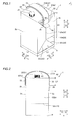
- the reagent container 1 includes a container body 2 storing the liquid reagent and a band-like grasp portion 3 to be grasped by the user in a state suspending the container body 2, as shown in Fig. 1 .
- the liquid reagent such as a diluent or a hemolyzer for a blood cell counter, which is an example of the analyzer, for example, is stored in the container body 2.
- the container body 2 has the shape of a rectangular parallelepiped with a width as well as a depth L1 and a height H1.
- the container body 2 is configured to be capable of storing the liquid reagent of about 4 liters.
- the container body 2 is made of a sheetlike material including a paper material, and formed by a sheetlike composite in which polyethylene, paper and a barrier film etc. are stacked, for example.
- the container body 2 has an upper surface 2a, a front surface 2b, side surfaces 2c and 2d, a back surface 2e and a bottom surface 2f, as shown in Figs. 1 to 4 .
- the container body 2 is provided in the form of the substantially rectangular parallelepiped shown in Fig. 1 by bringing the same into the shape of a substantially rectangular parallelepiped having an opened upper end, thereafter bringing the same into a closed structure by bonding the upper end (the open end) on bonded portions 2g, folding remaining extensional portions 2h toward the sides of both side surfaces 2c and 2d respectively and bonding the same.
- Various types of prints such as the type and the product name of the stored liquid reagent are applied to the respective side surfaces (the front surface 2b and the side surfaces 2c and 2d).
- a connecting port 21 for fluidly connecting the analyzer (not shown) and the container body 2 with each other is provided on the upper surface 2a of the container body 2.
- the connecting port 21 is formed to protrude upward (in a Z1 direction) from the upper surface 2a, and mounted with a cap 22 for opening/closing.
- the connecting port 21 is arranged on a position deviating toward the side of the front surface 2b (the side of a Y2 direction) from the center of the upper surface 2a in plan view, and the connecting port 21 is arranged on a position not overlapping the grasp portion 3 in the vertical direction (a Z direction).
- a connector 50 of the analyzer is connected to the connecting port 21 after the cap 22 (see Fig. 1 ) is detached from the connecting port 21, as shown in Fig. 5 .
- the connector 50 communicates with a tube 51 and has a suction tube (not shown) connected to the connector 50 to extend downward in the container body 2, so that the suction tube is inserted into the container body 2 when the user connects the connector 50 to the connecting port 21.
- the reagent in the container body 2 is sucked into the analyzer through the suction tube in the container body 2, the connector 50 and the tube 51.
- 2005/0191211 can be employed as such a suction tube and the connector.
- the connector 50 is connected to the connecting port 21 in order to use the analyzer, the same is used in the connected state until the reagent in the reagent container 1 is used and the user exchanges the reagent container 1 next.
- the container body 2 is provided with folds 23 for folding the container body 2 and changing the shape in disposal. More specifically, folds 23a vertically extending centers in a Y direction up to prescribed positions as well as folds 23b and 23c obliquely extending from both corner portions on the side of the bottom surface 2f up to lower ends of the folds 23a respectively are formed on both side surfaces 2c and 2d, as shown in Figs. 1 and 4 . Further, a fold 23d extending toward the side of the back surface 2e from joint portions of the folds 23a to 23c to connect both side surfaces 2c and 2d with each other across the back surface 2e (see Fig. 2 ) is formed on the container body 2.
- the grasp portion 3 includes a band-like member 30 and a protective member 40 provided to project from both edge portions 34 on the longitudinal side of the band-like member 30 respectively. Both ends of the band-like member 30 are so bonded to the side surfaces 2c and 2d of the container body 2 that the grasp portion 3 is mounted on the container body 2.
- the grasp portion 3 is configured to be separable from the container body 2 by removing the band-like member 30 in disposal.
- the grasp portion 3 is so provided that the band-like member 30 is in the form of an arc extending over the upper surface 2a of the container body 2 from a first end side (the side of the side surface 2c) to a second end side (the side of the side surface 2d). Therefore, the grasp portion 3 separates from the upper surface 2a of the container body 2 by the maximum height H2 at the center in the longitudinal direction.
- the height H2 is set to such a magnitude that the user easily inserts his/her hand between the grasp portion 3 and the upper surface 2a when grasping the grasp portion 3.
- the grasp portion 3 is arranged on a central portion of the container body 2 in the anteroposterior direction (the Y direction).
- the band-like member 30 has a length (the length in the longitudinal direction) L2, a width (the length in the short-side direction) W1 and a thickness t1.
- An adhesive is applied to the band-like member 30 over the whole of one surface (a lower surface 31). Therefore, the lower surface 31 of the band-like member 30 serves as an adhesive surface, and the band-like member 30 is bonded to both side surfaces 2c and 2d of the container body 2 on the side of this lower surface 31. No adhesive is applied to an upper surface 32 of the band-like member 30.
- the band-like member 30 regions of a length L3 on both ends serve as bonded regions 33 with respect to the container body 2.
- the length L3 of the bonded regions 33 is larger than the width W1 of the band-like member 30.
- the band-like member 30 is so configured that bond strength in directions (the Z direction and the Y direction) parallel to bonded surfaces is larger than bond strength in a normal direction (an X direction) orthogonal to the bonded surfaces (the side surfaces 2c and 2d).
- the band-like member 30 is bonded with bond strength capable of sufficiently supporting the weight of the container body 2 acting in the Z direction in a case where the user suspends the reagent container 1 by grasping the grasp portion 3.
- the bonded regions 33 are examples of the "mounted region” and the "bonded surface with respect to the container body" in the present invention.
- the band-like member 30 is so formed that the width W1 thereof is larger than the width Wg of the bonded portions 2g of the container body 2, and the band-like member 30 is bonded to partially overlap the bonded portions 2g in regions wider than the bonded portions 2g on both side surfaces 2c and 2d (the extensional portions 2h).
- the extensional portions 2h configured to overlap the side surface 2c (2d), are portions resistant against deformation in the container body 2. Therefore, the band-like member 30 is so bonded to the extensional portions 2h that the container body 2 can be inhibited from remarkably deforming when the user grasps the band-like member 30 to grasp the reagent container 1 in a suspended state.
- the protective member 40 is provided in order to protect fingers of the user when he/she grasps the grasp portion 3. As shown in Figs. 6 and 7 , the protective member 40 has a length (the length in the longitudinal direction) L4 and a width (the length in the short-side direction) W2, and is provided in the form of a sheet having a thickness t2.
- the protective member 40 is provided to project from both edge portions 34 on the longitudinal side of the band-like member 30 by a length Ld respectively. More specifically, the protective member 40 is so formed that the width W2 thereof is larger than the width W1 of the band-like member.
- waviness is frequently caused on a cut surface in either the longitudinal direction or the short-side direction. This waviness influences dimensional accuracy by expansion and contraction in the waviness direction. Therefore, the protective member 40 is so formed that waviness in the short-side direction appears on end surfaces 41. Thus, dimensional dispersion in the longitudinal direction of the protective member 40 is suppressed.
- the protective member 40 may simply project in the short-side direction from the edge portions 34 of the band-like member 30 in consideration of functions of the protective member 40 while the width W2 is sufficiently small as compared with the length L4, and hence there is hardly influence by dimensional dispersion resulting from waviness in the short-side direction of the protective member 40. Also in consideration of dimensional dispersion on the short side (in the width direction) resulting from waviness, the length Ld of the projecting portions of the protective member 40 is set to be at least about 1 mm and to be about several mm.
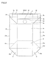
- FIG. 1 A folding procedure in disposal of the reagent container 1 is now described with reference to Figs. 1 to 3 and 8 .
- the user raises the extensional portions 2h while removing the same from both side surfaces 2c and 2d (see Fig. 2 ) respectively, in the state of Fig. 1 .
- the user raises the bonded portions 2g from the upper surface 2a, and thereafter flatly folds the upper portion of the container body 2 to match two corners of the upper surface 2a on the side of the front surface 2b and two corners on the side of the back surface 2e (see Fig. 3 ) with each other.
- the user mountain-folds centers of both side surfaces 2c and 2d in the Y direction along the folds 23a in the vertical direction, from the flattened upper portion toward the lower portion.
- the user doubles both side surfaces 2c and 2d along the folds 23a so that the front surface 2b and the back surface 2e coincide with each other.
- the user folds triangular side surface portions A surrounded by the obliquely extending folds 23b and 23c up to the bottom surface 2f (a set surface) outwardly in the X direction.
- the bottom portion of the reagent container 1 gets hexagonal (see Fig. 8 ) on the bottom surface 2f and the triangular side surface portions A on both sides of the bottom surface 2f in the X direction.
- the user folds halves of the hexagonal portions formed by the side surface portions A and the bottom surface 2f on the side of the back surface 2e along the folds 23d.
- the reagent container 1 is deformed into a flat folded state shown in Fig. 8 .
- the grasp portion 3 may be separated by removing the band-like member 30 before deforming the reagent container 1 or after deforming the same.
- the grasp portion 3 is provided with the band-like member 30 whose first and second end sides are mounted on the container body 2 and the protective member 40 provided on the band-like member 30 to project from the edge portions 34 on the longitudinal side of the band-like member 30, whereby the user can transport the reagent container 1 by grasping both of the band-like member 30 and the protective member 40.
- the protective member 40 projects from the edge portions 34 on the longitudinal side of the band-like member 30, whereby the protective member 40 can be reliably interposed between the edge portions 34 of the band-like member 30 and the fingers of the user.
- the edge portions 34 of the band-like member 30 can be inhibited from hurting the fingers of the user. From the above, the user can easily transport the reagent container 1 also in a case where the reagent container 1 is heavy with a large content weight in the reagent container 1 according to this embodiment.
- the protective member 40 is so formed that the width W2 thereof is larger than the width W1 of the band-like member 30 while the protective member 40 is provided to project from both edge portions 34 on the longitudinal side of the band-like member 30 respectively, whereby the protective member 40 can be reliably interposed between the fingers of the user and both edge portions 34 of the band-like member 30.
- the fingers of the user can be prevented from being cut or the like by the edge portions 34 of the thin band-like member 30, whereby the fingers of the user can be more effectively be inhibited from being hurt when grasping the grasp portion 3.
- the protective member 40 is so provided on the lower surface 31 of the band-like member 30 that the protective member 40 is arranged on the surface onto which the weight of the reagent container 1 is applied when the user grasps the grasp portion 3, whereby biting of the grasp portion 3 into the fingers of the user can be more effectively suppressed.
- the protective member 40 is provided substantially on the whole of the lower surface 31 of the band-like member 30 excluding the bonded regions 33 of the band-like member 30 to the container body 2, whereby the grasp portion 3 can be reliably inhibited by the protective member 40 from biting into the fingers of the user, regardless of a grasped position of the grasp portion 3.
- the protective member 40 is provided in the form of a sheet made of expanded polyethylene having elasticity, whereby the sheetlike protective member 40 can be easily provided on the band-like member 30. Further, a load applied to the fingers of the user can be relaxed due to the elasticity of the protective member 40.
- the protective member 40 is so made of the expanded polyethylene that a protective member lightweight and excellent in elasticity (shock absorptivity) can be provided on the grasp portion 3.
- a protective member lightweight and excellent in elasticity shock absorptivity
- the band-like member 30 made of synthetic paper mainly made of the polypropylene-based resin material is so provided that the grasp portion 3 can be rendered lightweight. Further, material consumption can be reduced as compared with a case of forming the grasp portion 3 by a resin-molded member or the like, whereby a load on the environment can be reduced.
- the container body 2 made of a sheetlike composite including a paper material is so provided that the reagent container 1 can be easily rendered lightweight.
- the folds 23 (23a to 23d) for changing the shape in disposal are so provided on the container body 2 that the container body 2 can be folded and compactified in disposal of the reagent container 1. Consequently, the volume in disposal decreases, whereby the load on the environment can be reduced also by this.
- the extensional portions 2h in which the sheetlike composite is folded over the side surface 2c (2d) are provided on the container body 2, and the band-like member 30 is mounted on the extensional portions 2h of the container body 2.
- the extensional portions 2h over which the sheetlike composite is folded are resistant against deformation, whereby deformation of the container body 2 can be suppressed also in a case where the user suspends the container body 2 by grasping the grasp portion 3.
- the grasp portion 3 is provided on the container body 2 to be arcuate from the first end toward the second end of the band-like member 30, whereby a clearance can be ensured between the grasp portion 3 and the upper surface 2a of the container body 2 by the height H2.
- the user can easily insert his/her hand into this clearance, whereby he/she can easily handle the reagent container 1.
- the grasp portion 3 is mounted to be separable from the container body 2 in disposal, whereby the grasp portion 3 and the container body 2 can be separately disposed by separating the grasp portion 3 in disposal, also when the container body 2 and the grasp portion 3 are made of different materials.
- the band-like member 30 is mounted on the side surfaces 2c and 2d of the container body 2 with the adhesive and so bonded that the bond strength in the directions (the Y direction and the Z direction) parallel to the bonded surfaces is larger than the bond strength in the normal direction (the X direction) orthogonal to the bonded surfaces, whereby the grasp portion 3 can be easily separated from the container body 2. Also in this case, the user can transport the reagent container 1 without detaching the grasp portion 3 from the container body 2 when transporting the same by grasping the grasp portion 3.
- the length L3 of the bonded regions 33 to the container body 2 in the longitudinal direction of the band-like member 30 is rendered larger than the width W1 in the short-side direction of the band-like member 30.
- the longitudinal direction of the band-like member 30 is the direction parallel to the bonded surfaces and the direction in which force acts in a case where the container body 2 is suspended through the grasp portion 3, whereby the grasp portion 3 can be effectively inhibited from coming off the container body 2 in transportation.
- the connecting port 21 for fluidly connecting the container body 2 and the analyzer with each other is provided on the container body 2, whereby the container body 2 and the analyzer can be connected with each other as such also in a case where the reagent container 1 is heavy with a large content weight. Therefore, the user can easily handle the reagent container 1 without requiring an operation of exchanging the liquid reagent or the like.
- the connecting port 21 is arranged on the position not overlapping the grasp portion 3 on the upper surface 2a of the container body 2 in plan view so that the grasp portion 3 does not hinder when the user connects the connecting port 21 to the side of the analyzer, whereby workability at the time of connecting the connecting port 21 to the side of the analyzer can be improved.
- the container body 2 substantially in the form of a rectangular parallelepiped is so provided that reagent containers 1 can be lined up with no clearance in transportation.
- transportation efficiency for the reagent containers 1 increases, whereby a load on the environment can be reduced.
- the example in which the present invention is applied to the reagent container storing the liquid reagent (a diluent or a hemolyzer) for a blood cell counter has been shown.
- the reagent container 1 used for the blood cell counter employing a relatively large quantity of reagent becomes easy.
- the diluent or the hemolyzer is generally used in a relatively large quantity in the blood cell counter, and hence the reagent container 1 according to this embodiment is particularly effective as a reagent container for a diluent or a hemolyzer.
- the present invention is not restricted to this.
- the present invention may be applied to a reagent container for a liquid reagent employed for a urine visible component analyzer.
- a reagent other than the diluent or the hemolyzer may be stored as the liquid reagent.
- the liquid reagent may be a detergent or a sheath liquid.
- the present invention is not restricted to this.
- a resin-molded container such as the so-called poly-container or a flexible baglike container made of resin may be employed as the container body.
- the container body may be made of a material other than the resin.
- the band-like member may be made of synthetic resin mainly made of a resin material other than the polypropylene-based material or a paper material other than the synthetic paper. Further, the band-like member may be made of a material other than these. A thin, lightweight and strong material is preferable for the band-like member in points of material consumption and easiness of transportation. Also in a case of employing such a thin and strong band-like member, it is possible to protect the fingers of the user with the protective member according to the present invention.
- the protective member may be made of a foaming resin material other than the expanded polyethylene or a resin material such as a rubber sheet other than the foaming resin material. Further, the protective member may be made of a material other than these.
- a protective member 40 may be provided on the side of an upper surface 32 of a band-like member 30, as in a grasp portion 3a according to a first modification shown in Fig. 9 . Also when configuring the reagent container 1 in this manner, the protective member 40 can be interposed between edge portions 34 of the band-like member 30 and the fingers of the user to protect the fingers when the user grasps the grasp portion.
- two protective members 140 may be provided to project from both edge portions 34 of a band-like member 30 respectively, as in a grasp portion 3b according to a second modification shown in Fig. 10 .
- a protective member may be so provided that the protective member projects from only an edge portion on one side of a band-like member.
- the band-like member 30 can be prevented from being creased in the width direction and narrowed in the case where the user grasps the grasp portion 3, whereby a load can be inhibited from concentrating on the fingers of the user.
- protective members 240 may be provided to project from edge portions 34 on both sides of an upper surface 32 and a lower surface 31 of a band-like member 30 to wrap the edge portions 34 of the band-like member 30, as in a grasp portion 3c according to a third modification shown in Fig. 11 .
- a protective member 340 may be provided only on a prescribed region in the vicinity of a central portion in the longitudinal direction (an X direction) of a band-like member 30, as in a grasp portion 3d according to a fourth modification shown in Fig. 12 .
- the protective member 340 When providing the protective member 340 at least on the prescribed region in the vicinity of the central portion in the longitudinal direction of the band-like member 30 as in this fourth modification, the protective member 340 is provided on the central portion of the band-like member 30 having a high possibility of being grasped by the user, whereby the user can be easily made to grasp a region where the protective member 340 is formed when the user grasps the grasp portion 3d.
- the protective member may be provided on a portion other than the central portion in the longitudinal direction of the band-like member.
- the container body may be provided in the form of a cylinder or a cube other than the rectangular parallelepiped.
- the grasp portion may be integrally formed on the container body, for example, not to be separable. Description of Reference Signs
Landscapes
- Engineering & Computer Science (AREA)
- Mechanical Engineering (AREA)
- Health & Medical Sciences (AREA)
- Chemical & Material Sciences (AREA)
- Medicinal Chemistry (AREA)
- Clinical Laboratory Science (AREA)
- Chemical Kinetics & Catalysis (AREA)
- Details Of Rigid Or Semi-Rigid Containers (AREA)
- Investigating Or Analysing Biological Materials (AREA)
- Packages (AREA)
- Automatic Analysis And Handling Materials Therefor (AREA)
- Cartons (AREA)
Abstract
Description
- The present invention relates to a reagent container, and more particularly, it relates to a reagent container for storing a liquid reagent employed for an analyzer.
- In general, various types of liquid reagents are used in an analyzer. Depending on measurement items of the analyzer or the throughput of the analyzer, a reagent container storing a liquid reagent of a somewhat large quantity of about 5 liters, for example, may be employed. Such a container enlarges both in weight and volume, and hence handling such as transportation has been inconvenient. A container described in Japanese Patent Laid-Open No.
6-345077 - A container having a tapelike handle is disclosed in the aforementioned Japanese Patent Laid-Open No.
6-345077 - Patent Document 1: Japanese Patent Laid-Open No.
6-345077 - According to the technique described in the aforementioned Japanese Patent Laid-Open No.
6-345077 - The present invention has been proposed in order to solve the aforementioned problem, and one object of the present invention is to provide a reagent container easily transportable also in a case where the same is heavy with a large content weight.
- In order to attain the aforementioned object, a reagent container according to one aspect of the present invention includes a container body for storing a liquid reagent employed for an analyzer and a band-like grasp portion mounted on the container body so that the user grasps the container body in a suspended state, while the grasp portion includes a band-like member whose first and second end sides are mounted on the container body and a protective member provided on the band-like member to project from an edge portion of the band-like member.
- In the reagent container according to the aspect of the present invention, as hereinabove described, the grasp portion is provided with the band-like member whose first and second end sides are mounted on the container body and the protective member provided on the band-like member to project from the edge portion of the band-like member so that the user can transport the reagent container by grasping both of the band-like member and the protective member, whereby biting of the grasp portion into fingers of the user is suppressed by the protective member and the user can be inhibited from feeling a pain. Further, the protective member projects from the edge portion of the band-like member, whereby the protective member can be reliably interposed between the edge portion of the band-like member and the fingers of the user. Consequently, the edge portion of the band-like member can be inhibited from hurting the fingers of the user. From the above, the reagent container can be easily transported according to the present invention, also in a case where the reagent container is heavy with a large content weight.
- Preferably in the reagent container according to the aforementioned aspect, the protective member is so formed that the width thereof in the short-side direction of the band-like member is larger than the width in the short-side direction of the band-like member, and the protective member is provided to project from both edge portions on the longitudinal side of the band-like member respectively. When constituted in this manner, the protective member can be reliably interposed between the fingers of the user and both edge portions of the band-like member respectively, whereby the edge portions of the band-like member can be effectively inhibited from hurting the fingers of the user.
- Preferably in the reagent container according to the aforementioned aspect, the protective member is at least provided on a prescribed region in the vicinity of a central portion in the longitudinal direction of the band-like member. When constituted in this manner, the protective member is provided on the central portion of the band-like member having a high possibility of being grasped by the user, whereby the user can be made to easily grasp the region where the protective member is formed when the user grasps the grasp portion.
- Preferably in the reagent container according to the aforementioned aspect, the band-like member has a first surface opposed to the upper surface of the container body and a second surface which is the other side of the first surface, and the protective member is provided on the first surface of the band-like member. When constituted in this manner, the protective member is arranged on the surface on which the weight of the reagent container is applied when the user grasps the grasp portion, whereby biting of the grasp portion into the fingers of the user can be more effectively suppressed.
- Preferably in this case, the protective member is provided substantially on the whole of the first surface of the band-like member except for a mounted region of the band-like member onto the container body. When constituted in this manner, the grasp portion can be reliably inhibited by the protective member from biting into the fingers of the user, regardless of a grasped position of the grasp portion.
- Preferably in the reagent container according to the aforementioned aspect, the protective member has elasticity, and is provided in the form of a sheet. When constituted in this manner, the sheetlike protective member can be easily provided on the band-like member, while a load applied to the fingers of the user can be relaxed due to the elasticity of the protective member.
- Preferably in the reagent container according to the aforementioned aspect, the band-like member is made of synthetic paper. When constituted in this manner, the grasp portion can be rendered lightweight. Further, material consumption can be reduced as compared with a case of forming the grasp portion by a resin-molded member or the like, whereby a load on the environment can be reduced.
- Preferably in the reagent container according to the aforementioned aspect, the protective member is made of a foaming resin material. When constituted in this manner, a protective member lightweight and excellent in elasticity (shock absorptivity) can be provided on the grasp portion by employing a spongy foaming resin material, for example. Thus, biting of the grasp portion into the fingers of the user is effectively suppressed by the protective member made of the foaming resin material, whereby the user can be effectively inhibited from feeling a pain when transporting the reagent container by grasping the grasp portion.
- Preferably in the reagent container according to the aforementioned aspect, the container body is made of a sheetlike material including a paper material. When constituted in this manner, the reagent container can be easily rendered lightweight.
- Preferably in this case, the container body has a fold for changing the shape in disposal. When constituted in this manner, the container body can be folded and compactified in disposal of the reagent container. Consequently, the volume in disposal decreases, whereby the load on the environment can be reduced also by this.
- Preferably in the aforementioned structure in which the container body is made of the sheetlike material including a paper material, the container body has a side surface portion over which the sheetlike material is folded, and the first and second end sides of the band-like member are mounted on the side surface portion of the container body. When constituted in this manner, the side surface portion over which the sheetlike material is folded is so resistant against deformation that deformation of the container body can be suppressed also in a case where the user suspends the container body by grasping the grasp portion.
- Preferably in the reagent container according to the aforementioned aspect, the grasp portion is mounted on the container body to be arcuate from the first end toward the second end of the band-like member. When constituted in this manner, a clearance can be ensured between the grasp portion and the upper surface of the container, whereby the user can easily insert his/her hand into this clearance. Therefore, the reagent container can be easily handled.
- Preferably in the reagent container according to the aforementioned aspect, the grasp portion is mounted to be separable from the container body. When constituted in this manner, the grasp portion and the container body can be separately disposed by separating the grasp portion in disposal, also when the container body and the grasp portion are made of different materials.
- Preferably in this case, the band-like member is mounted on a side surface of the container body with an adhesive, and so bonded that bond strength in a direction parallel to a bonded surface is larger than bond strength in a direction orthogonal to the bonded surface. When constituted in this manner, the grasp portion does not come off the container body when the user transports the reagent container by grasping the grasp portion, while he/she can easily separate the grasp portion by pulling off the same in the direction orthogonal to the bonded surface when separating the grasp portion from the container body.
- Preferably in the aforementioned structure in which the band-like member is mounted on the side surface of the container body with the adhesive, the length of the bonded surface with respect to the container body in the longitudinal direction of the band-like member is larger than the width in the short-side direction of the band-like member. When constituted in this manner, the bond strength of the bonded surface in the longitudinal direction of the band-like member can be enlarged. The longitudinal direction of the band-like member is the direction parallel to the bonded surface and a direction in which force acts in a case where the container body is suspended through the grasp portion, whereby the grasp portion can be effectively inhibited from coming off the container body in transportation.
- Preferably in the reagent container according to the aforementioned aspect, the container body has a connecting port for fluidly connecting the container body and the analyzer with each other. When constituted in this manner, the container body and the analyzer can be connected with each other as such also in a case where the reagent container is heavy with a large content weight, whereby the reagent container can be easily handled.
- Preferably in this case, the connecting port is arranged on the upper surface of the container body on a position not overlapping the grasp portion in plan view. When constituted in this manner, the grasp portion does not hinder when the user connects the connecting port to the side of the analyzer, whereby workability at the time of connecting the connecting port to the analyzer can be improved.
- Preferably in the reagent container according to the aforementioned aspect, the container body has an outer shape substantially in the form of a rectangular parallelepiped. When constituted in this manner, reagent containers can be lined up with no clearance in transportation, whereby transportation efficiency is excellent and a load on the environment can be reduced.
- Preferably in the reagent container according to the aforementioned aspect, the liquid reagent is a reagent for a blood cell counter or a reagent for a urine visible component analyzer. Reagents employed for a blood cell counter include a diluent, a hemolyzer, a detergent and the like. On the other hand, reagents employed for a urine visible component analyzer include a diluent, a detergent and the like. Each of these analyzers such as the blood cell counter and the urine visible component analyzer, classifying·counting cells in a liquid, dilutes a vital sample to a prescribed magnification with the diluent or the hemolyzer, or executes a cleaning operation of a fluid system of the analyzer by employing the diluent or the detergent. In an analyzer utilizing flow cytometry, a sheath liquid to be fed along with a sample liquid in order to form a laminar flow of a sample liquid containing cells in a flow cell is also employed. Therefore, the quantity of the reagent used in each analysis increases. Further, the frequency of analysis in one analyzer may exceed several 100 times a day depending on the scale of medical facilities using the analyzer, and hence a container of a magnitude capable of storing reagents employed for analysis of several 100 to several 1000 times may be employed in order to reduce frequency of performing reagent exchange operations. Due to such circumstances, a container storing a reagent for a blood cell counter or a reagent for a urine visible component analyzer tends to be large-sized. Therefore, the present invention is particularly effective in a case where the same is applied to a reagent container for such a reagent for a blood cell counter or a reagent for a urine visible component analyzer, and transportation or handling of the reagent container by an inspection engineer using the blood cell counter or the urine visible component analyzer becomes easy.
- Preferably in this case, the liquid reagent is a diluent, a hemolyzer or a detergent. A relatively large quantity of the diluent or the hemolyzer is used in the analyzer as hereinabove described, and hence the present invention is particularly effective in a case where the same is applied to a reagent container for a diluent, a hemolyzer or a detergent.
-
- [
Fig. 1 ] A perspective view showing the appearance of a reagent container according to an embodiment of the present invention. - [
Fig. 2 ] A front elevational view of the reagent container according to the embodiment shown inFig. 1 . - [
Fig. 3 ] A top plan view of the reagent container according to the embodiment shown inFig. 1 . - [
Fig. 4 ] A side elevational view of the reagent container according to the embodiment shown inFig. 1 . - [
Fig. 5 ] A perspective view showing a state where the reagent container shown inFig. 1 is connected with an analyzer. - [
Fig. 6 ] A bottom plan view showing a grasp portion of the reagent container according to the embodiment shown inFig. 1 . - [
Fig. 7 ] An enlarged sectional view showing the grasp portion of the reagent container according to the embodiment shown inFig. 1 . - [
Fig. 8 ] A diagram showing a state of folding the reagent container shown inFig. 1 when disposing the same. - [
Fig. 9 ] An enlarged sectional view showing a grasp portion in a first modification of the reagent container according to the embodiment of the present invention. - [
Fig. 10 ] An enlarged sectional view showing a grasp portion in a second modification of the reagent container according to the embodiment of the present invention. - [
Fig. 11 ] An enlarged sectional view showing a grasp portion in a third modification of the reagent container according to the embodiment of the present invention. - [
Fig. 12 ] A perspective view for illustrating a grasp portion in a fourth modification of the reagent container according to the embodiment of the present invention. - An embodiment materializing the present invention is now described on the basis of the drawings. The dimensions and the content weight of a reagent container disclosed in the following embodiment are mere examples, and the present invention is not restricted to these.
- First, the overall structure of a
reagent container 1 according to the embodiment of the present invention is described with reference toFigs. 1 to 8 . - The
reagent container 1 according to this embodiment stores a liquid reagent employed for an analyzer performing sample analysis. Thereagent container 1 includes acontainer body 2 storing the liquid reagent and a band-like grasp portion 3 to be grasped by the user in a state suspending thecontainer body 2, as shown inFig. 1 . The liquid reagent such as a diluent or a hemolyzer for a blood cell counter, which is an example of the analyzer, for example, is stored in thecontainer body 2. - The
container body 2 has the shape of a rectangular parallelepiped with a width as well as a depth L1 and a height H1. Thecontainer body 2 is configured to be capable of storing the liquid reagent of about 4 liters. Thecontainer body 2 is made of a sheetlike material including a paper material, and formed by a sheetlike composite in which polyethylene, paper and a barrier film etc. are stacked, for example. Thecontainer body 2 has anupper surface 2a, afront surface 2b, side surfaces 2c and 2d, aback surface 2e and abottom surface 2f, as shown inFigs. 1 to 4 . - The
container body 2 is provided in the form of the substantially rectangular parallelepiped shown inFig. 1 by bringing the same into the shape of a substantially rectangular parallelepiped having an opened upper end, thereafter bringing the same into a closed structure by bonding the upper end (the open end) on bondedportions 2g, folding remainingextensional portions 2h toward the sides of bothside surfaces front surface 2b and the side surfaces 2c and 2d). - A connecting
port 21 for fluidly connecting the analyzer (not shown) and thecontainer body 2 with each other is provided on theupper surface 2a of thecontainer body 2. The connectingport 21 is formed to protrude upward (in a Z1 direction) from theupper surface 2a, and mounted with acap 22 for opening/closing. As shown inFig. 3 , the connectingport 21 is arranged on a position deviating toward the side of thefront surface 2b (the side of a Y2 direction) from the center of theupper surface 2a in plan view, and the connectingport 21 is arranged on a position not overlapping thegrasp portion 3 in the vertical direction (a Z direction). In use of thereagent container 1, aconnector 50 of the analyzer is connected to the connectingport 21 after the cap 22 (seeFig. 1 ) is detached from the connectingport 21, as shown inFig. 5 . Theconnector 50 communicates with atube 51 and has a suction tube (not shown) connected to theconnector 50 to extend downward in thecontainer body 2, so that the suction tube is inserted into thecontainer body 2 when the user connects theconnector 50 to the connectingport 21. In use of the analyzer, the reagent in thecontainer body 2 is sucked into the analyzer through the suction tube in thecontainer body 2, theconnector 50 and thetube 51. Those having structures disclosed in Japanese Patent Laid-Open No.9-297146 U.S. Patent Application Publication No. 2005/0191211 , for example, can be employed as such a suction tube and the connector. Once theconnector 50 is connected to the connectingport 21 in order to use the analyzer, the same is used in the connected state until the reagent in thereagent container 1 is used and the user exchanges thereagent container 1 next. - The
container body 2 is provided withfolds 23 for folding thecontainer body 2 and changing the shape in disposal. More specifically, folds 23a vertically extending centers in a Y direction up to prescribed positions as well asfolds bottom surface 2f up to lower ends of thefolds 23a respectively are formed on bothside surfaces Figs. 1 and4 . Further, afold 23d extending toward the side of theback surface 2e from joint portions of thefolds 23a to 23c to connect bothside surfaces back surface 2e (seeFig. 2 ) is formed on thecontainer body 2. - As shown in
Figs. 1 to 4 , thegrasp portion 3 includes a band-like member 30 and aprotective member 40 provided to project from bothedge portions 34 on the longitudinal side of the band-like member 30 respectively. Both ends of the band-like member 30 are so bonded to the side surfaces 2c and 2d of thecontainer body 2 that thegrasp portion 3 is mounted on thecontainer body 2. Thegrasp portion 3 is configured to be separable from thecontainer body 2 by removing the band-like member 30 in disposal. - As shown in
Fig. 2 , thegrasp portion 3 is so provided that the band-like member 30 is in the form of an arc extending over theupper surface 2a of thecontainer body 2 from a first end side (the side of theside surface 2c) to a second end side (the side of theside surface 2d). Therefore, thegrasp portion 3 separates from theupper surface 2a of thecontainer body 2 by the maximum height H2 at the center in the longitudinal direction. The height H2 is set to such a magnitude that the user easily inserts his/her hand between thegrasp portion 3 and theupper surface 2a when grasping thegrasp portion 3. As shown inFig. 3 , thegrasp portion 3 is arranged on a central portion of thecontainer body 2 in the anteroposterior direction (the Y direction). - As shown in
Figs. 6 and 7 , the band-like member 30 has a length (the length in the longitudinal direction) L2, a width (the length in the short-side direction) W1 and a thickness t1. The band-like member 30 is made of synthetic paper, having a thickness (t1 =) of about 0.1 mm, mainly made of a polypropylene-based resin material. An adhesive is applied to the band-like member 30 over the whole of one surface (a lower surface 31). Therefore, thelower surface 31 of the band-like member 30 serves as an adhesive surface, and the band-like member 30 is bonded to bothside surfaces container body 2 on the side of thislower surface 31. No adhesive is applied to anupper surface 32 of the band-like member 30. - In the band-
like member 30, regions of a length L3 on both ends serve as bondedregions 33 with respect to thecontainer body 2. The length L3 of the bondedregions 33 is larger than the width W1 of the band-like member 30. As shown inFig. 2 , the band-like member 30 is so configured that bond strength in directions (the Z direction and the Y direction) parallel to bonded surfaces is larger than bond strength in a normal direction (an X direction) orthogonal to the bonded surfaces (the side surfaces 2c and 2d). The band-like member 30 is bonded with bond strength capable of sufficiently supporting the weight of thecontainer body 2 acting in the Z direction in a case where the user suspends thereagent container 1 by grasping thegrasp portion 3. When the user disposes thereagent container 1, on the other hand, it is possible to easily separate thegrasp portion 3 from thecontainer body 2 by pulling off the band-like member 30 in the normal direction (the X direction) orthogonal to the bonded surfaces (the side surfaces 2c and 2d). The bondedregions 33 are examples of the "mounted region" and the "bonded surface with respect to the container body" in the present invention. - As shown in
Figs. 1 and4 , the band-like member 30 is so formed that the width W1 thereof is larger than the width Wg of the bondedportions 2g of thecontainer body 2, and the band-like member 30 is bonded to partially overlap the bondedportions 2g in regions wider than the bondedportions 2g on bothside surfaces extensional portions 2h). Theextensional portions 2h, configured to overlap theside surface 2c (2d), are portions resistant against deformation in thecontainer body 2. Therefore, the band-like member 30 is so bonded to theextensional portions 2h that thecontainer body 2 can be inhibited from remarkably deforming when the user grasps the band-like member 30 to grasp thereagent container 1 in a suspended state. - The
protective member 40 is provided in order to protect fingers of the user when he/she grasps thegrasp portion 3. As shown inFigs. 6 and 7 , theprotective member 40 has a length (the length in the longitudinal direction) L4 and a width (the length in the short-side direction) W2, and is provided in the form of a sheet having a thickness t2. Theprotective member 40 is made of expanded polyethylene of a thickness (t2 =) of about 2 mm having elasticity. - The
protective member 40 is bonded to thelower surface 31 of the band-like member 30 opposed to theupper surface 2a of thecontainer body 2, and fixed to the band-like member 30. More specifically, theprotective member 40 is stuck to a bonded region of the length L4 (L4 = L2 - (2 x L3)) at the center of the band-like member 30. In other words, theprotective member 40 is provided substantially on the whole of thelower surface 31 excluding the bondedregions 33 of the band-like member 30 to thecontainer body 2. - According to this embodiment, the
protective member 40 is provided to project from bothedge portions 34 on the longitudinal side of the band-like member 30 by a length Ld respectively. More specifically, theprotective member 40 is so formed that the width W2 thereof is larger than the width W1 of the band-like member. Theprotective member 40 is bonded to the band-like member 30 in a state of matching the center in the width direction (the short-side direction) with the band-like member 30. Therefore, theprotective member 40 projects in the short-side direction by the length Ld (Ld = (W2 - W1)/2) responsive to the difference between the width W2 and the width W1. - When forming (cutting) a sheetlike member such as the
protective member 40 in prescribed dimensions, waviness is frequently caused on a cut surface in either the longitudinal direction or the short-side direction. This waviness influences dimensional accuracy by expansion and contraction in the waviness direction. Therefore, theprotective member 40 is so formed that waviness in the short-side direction appears on end surfaces 41. Thus, dimensional dispersion in the longitudinal direction of theprotective member 40 is suppressed. Theprotective member 40 may simply project in the short-side direction from theedge portions 34 of the band-like member 30 in consideration of functions of theprotective member 40 while the width W2 is sufficiently small as compared with the length L4, and hence there is hardly influence by dimensional dispersion resulting from waviness in the short-side direction of theprotective member 40. Also in consideration of dimensional dispersion on the short side (in the width direction) resulting from waviness, the length Ld of the projecting portions of theprotective member 40 is set to be at least about 1 mm and to be about several mm. - A folding procedure in disposal of the
reagent container 1 is now described with reference toFigs. 1 to 3 and8 . - First, the user raises the
extensional portions 2h while removing the same from bothside surfaces Fig. 2 ) respectively, in the state ofFig. 1 . Then, the user raises the bondedportions 2g from theupper surface 2a, and thereafter flatly folds the upper portion of thecontainer body 2 to match two corners of theupper surface 2a on the side of thefront surface 2b and two corners on the side of theback surface 2e (seeFig. 3 ) with each other. Then, the user mountain-folds centers of bothside surfaces folds 23a in the vertical direction, from the flattened upper portion toward the lower portion. In other words, the user doubles bothside surfaces folds 23a so that thefront surface 2b and theback surface 2e coincide with each other. - Further, the user folds triangular side surface portions A surrounded by the obliquely extending
folds bottom surface 2f (a set surface) outwardly in the X direction. At this time, the bottom portion of thereagent container 1 gets hexagonal (seeFig. 8 ) on thebottom surface 2f and the triangular side surface portions A on both sides of thebottom surface 2f in the X direction. - Finally, the user folds halves of the hexagonal portions formed by the side surface portions A and the
bottom surface 2f on the side of theback surface 2e along thefolds 23d. Thus, thereagent container 1 is deformed into a flat folded state shown inFig. 8 . While thereagent container 1 is folded in a state leaving thegrasp portion 3 inFig. 8 in order to facilitate easy understanding of the positional relation between the respective portions, thegrasp portion 3 may be separated by removing the band-like member 30 before deforming thereagent container 1 or after deforming the same. - According to this embodiment, as hereinabove described, the
grasp portion 3 is provided with the band-like member 30 whose first and second end sides are mounted on thecontainer body 2 and theprotective member 40 provided on the band-like member 30 to project from theedge portions 34 on the longitudinal side of the band-like member 30, whereby the user can transport thereagent container 1 by grasping both of the band-like member 30 and theprotective member 40. Thus, biting of thegrasp portion 3 into the fingers of the user is suppressed by theprotective member 40 and the user can be inhibited from feeling a pain. Further, theprotective member 40 projects from theedge portions 34 on the longitudinal side of the band-like member 30, whereby theprotective member 40 can be reliably interposed between theedge portions 34 of the band-like member 30 and the fingers of the user. Consequently, theedge portions 34 of the band-like member 30 can be inhibited from hurting the fingers of the user. From the above, the user can easily transport thereagent container 1 also in a case where thereagent container 1 is heavy with a large content weight in thereagent container 1 according to this embodiment. - According to this embodiment, as hereinabove described, the
protective member 40 is so formed that the width W2 thereof is larger than the width W1 of the band-like member 30 while theprotective member 40 is provided to project from bothedge portions 34 on the longitudinal side of the band-like member 30 respectively, whereby theprotective member 40 can be reliably interposed between the fingers of the user and bothedge portions 34 of the band-like member 30. Thus, the fingers of the user can be prevented from being cut or the like by theedge portions 34 of the thin band-like member 30, whereby the fingers of the user can be more effectively be inhibited from being hurt when grasping thegrasp portion 3. - According to this embodiment, as hereinabove described, the
protective member 40 is so provided on thelower surface 31 of the band-like member 30 that theprotective member 40 is arranged on the surface onto which the weight of thereagent container 1 is applied when the user grasps thegrasp portion 3, whereby biting of thegrasp portion 3 into the fingers of the user can be more effectively suppressed. - According to this embodiment, as hereinabove described, the
protective member 40 is provided substantially on the whole of thelower surface 31 of the band-like member 30 excluding the bondedregions 33 of the band-like member 30 to thecontainer body 2, whereby thegrasp portion 3 can be reliably inhibited by theprotective member 40 from biting into the fingers of the user, regardless of a grasped position of thegrasp portion 3. - According to this embodiment, as hereinabove described, the
protective member 40 is provided in the form of a sheet made of expanded polyethylene having elasticity, whereby the sheetlikeprotective member 40 can be easily provided on the band-like member 30. Further, a load applied to the fingers of the user can be relaxed due to the elasticity of theprotective member 40. In addition, theprotective member 40 is so made of the expanded polyethylene that a protective member lightweight and excellent in elasticity (shock absorptivity) can be provided on thegrasp portion 3. Thus, biting of thegrasp portion 3 into the fingers of the user is effectively suppressed by theprotective member 40 made of the expanded polyethylene, whereby the user can be more effectively inhibited from feeling a pain when transporting thereagent container 1 by grasping thegrasp portion 3. - According to this embodiment, as hereinabove described, the band-
like member 30 made of synthetic paper mainly made of the polypropylene-based resin material is so provided that thegrasp portion 3 can be rendered lightweight. Further, material consumption can be reduced as compared with a case of forming thegrasp portion 3 by a resin-molded member or the like, whereby a load on the environment can be reduced. - According to this embodiment, as hereinabove described, the
container body 2 made of a sheetlike composite including a paper material is so provided that thereagent container 1 can be easily rendered lightweight. - According to this embodiment, as hereinabove described, the folds 23 (23a to 23d) for changing the shape in disposal are so provided on the
container body 2 that thecontainer body 2 can be folded and compactified in disposal of thereagent container 1. Consequently, the volume in disposal decreases, whereby the load on the environment can be reduced also by this. - According to this embodiment, as hereinabove described, the
extensional portions 2h in which the sheetlike composite is folded over theside surface 2c (2d) are provided on thecontainer body 2, and the band-like member 30 is mounted on theextensional portions 2h of thecontainer body 2. Thus, theextensional portions 2h over which the sheetlike composite is folded are resistant against deformation, whereby deformation of thecontainer body 2 can be suppressed also in a case where the user suspends thecontainer body 2 by grasping thegrasp portion 3. - According to this embodiment, as hereinabove described, the
grasp portion 3 is provided on thecontainer body 2 to be arcuate from the first end toward the second end of the band-like member 30, whereby a clearance can be ensured between thegrasp portion 3 and theupper surface 2a of thecontainer body 2 by the height H2. Thus, the user can easily insert his/her hand into this clearance, whereby he/she can easily handle thereagent container 1. - According to this embodiment, as hereinabove described, the
grasp portion 3 is mounted to be separable from thecontainer body 2 in disposal, whereby thegrasp portion 3 and thecontainer body 2 can be separately disposed by separating thegrasp portion 3 in disposal, also when thecontainer body 2 and thegrasp portion 3 are made of different materials. - According to this embodiment, as hereinabove described, the band-
like member 30 is mounted on the side surfaces 2c and 2d of thecontainer body 2 with the adhesive and so bonded that the bond strength in the directions (the Y direction and the Z direction) parallel to the bonded surfaces is larger than the bond strength in the normal direction (the X direction) orthogonal to the bonded surfaces, whereby thegrasp portion 3 can be easily separated from thecontainer body 2. Also in this case, the user can transport thereagent container 1 without detaching thegrasp portion 3 from thecontainer body 2 when transporting the same by grasping thegrasp portion 3. - According to this embodiment, as hereinabove described, the length L3 of the bonded
regions 33 to thecontainer body 2 in the longitudinal direction of the band-like member 30 is rendered larger than the width W1 in the short-side direction of the band-like member 30. Thus, the bond strength of the bonded surfaces to the longitudinal direction (the Z direction inFig. 1 ) of the band-like member 30 can be increased. The longitudinal direction of the band-like member 30 is the direction parallel to the bonded surfaces and the direction in which force acts in a case where thecontainer body 2 is suspended through thegrasp portion 3, whereby thegrasp portion 3 can be effectively inhibited from coming off thecontainer body 2 in transportation. - According to this embodiment, as hereinabove described, the connecting
port 21 for fluidly connecting thecontainer body 2 and the analyzer with each other is provided on thecontainer body 2, whereby thecontainer body 2 and the analyzer can be connected with each other as such also in a case where thereagent container 1 is heavy with a large content weight. Therefore, the user can easily handle thereagent container 1 without requiring an operation of exchanging the liquid reagent or the like. - According to this embodiment, as hereinabove described, the connecting
port 21 is arranged on the position not overlapping thegrasp portion 3 on theupper surface 2a of thecontainer body 2 in plan view so that thegrasp portion 3 does not hinder when the user connects the connectingport 21 to the side of the analyzer, whereby workability at the time of connecting the connectingport 21 to the side of the analyzer can be improved. - According to this embodiment, as hereinabove described, the
container body 2 substantially in the form of a rectangular parallelepiped is so provided thatreagent containers 1 can be lined up with no clearance in transportation. Thus, transportation efficiency for thereagent containers 1 increases, whereby a load on the environment can be reduced. - In this embodiment, as hereinabove described, the example in which the present invention is applied to the reagent container storing the liquid reagent (a diluent or a hemolyzer) for a blood cell counter has been shown. Thus, transportation or handling of the
reagent container 1 used for the blood cell counter employing a relatively large quantity of reagent becomes easy. Further, the diluent or the hemolyzer is generally used in a relatively large quantity in the blood cell counter, and hence thereagent container 1 according to this embodiment is particularly effective as a reagent container for a diluent or a hemolyzer. - The embodiment disclosed this time must be considered as illustrative in all points and not restrictive. The range of the present invention is shown not by the above description of the embodiment but by the scope of claims for patent, and all modifications within the meaning and range equivalent to the scope of claims for patent are included.
- For example, while the example of applying the present invention to the reagent container storing the liquid reagent (a diluent or a hemolyzer) for the blood cell counter has been shown in the aforementioned embodiment, the present invention is not restricted to this. For example, the present invention may be applied to a reagent container for a liquid reagent employed for a urine visible component analyzer. Further, a reagent other than the diluent or the hemolyzer may be stored as the liquid reagent. For example, the liquid reagent may be a detergent or a sheath liquid.
- While the example of forming the container body by the composite in which polyethylene, paper and a barrier film etc. are stacked has been shown in the aforementioned embodiment, the present invention is not restricted to this. According to the present invention, a resin-molded container such as the so-called poly-container or a flexible baglike container made of resin may be employed as the container body. In addition, the container body may be made of a material other than the resin.
- While the example of forming the band-like member of the grasp portion by the synthetic paper mainly made of the polypropylene-based resin material has been shown in the aforementioned embodiment, the present invention is not restricted to this. According to the present invention, the band-like member may be made of synthetic resin mainly made of a resin material other than the polypropylene-based material or a paper material other than the synthetic paper. Further, the band-like member may be made of a material other than these. A thin, lightweight and strong material is preferable for the band-like member in points of material consumption and easiness of transportation. Also in a case of employing such a thin and strong band-like member, it is possible to protect the fingers of the user with the protective member according to the present invention.
- While the example of forming the protective member of the grasp portion by the expanded polyethylene has been shown in the aforementioned embodiment, the present invention is not restricted to this. According to the present invention, the protective member may be made of a foaming resin material other than the expanded polyethylene or a resin material such as a rubber sheet other than the foaming resin material. Further, the protective member may be made of a material other than these.
- While the example of providing the protective member on the lower surface of the band-like member opposed to the upper surface of the container body has been shown in the aforementioned embodiment, the present invention is not restricted to this. According to the present invention, a
protective member 40 may be provided on the side of anupper surface 32 of a band-like member 30, as in agrasp portion 3a according to a first modification shown inFig. 9 . Also when configuring thereagent container 1 in this manner, theprotective member 40 can be interposed betweenedge portions 34 of the band-like member 30 and the fingers of the user to protect the fingers when the user grasps the grasp portion. - While the example of rendering the width W2 of the protective member larger than the width W1 of the band-like member so that the protective member projects from both edge portions of the band-like member respectively has been shown in the aforementioned embodiment, the present invention is not restricted to this. According to the present invention, two
protective members 140 may be provided to project from bothedge portions 34 of a band-like member 30 respectively, as in agrasp portion 3b according to a second modification shown inFig. 10 . Alternatively, a protective member may be so provided that the protective member projects from only an edge portion on one side of a band-like member. In the case of providing theprotective member 40 wider than the band-like member 30 over the whole width of the band-like member 30 as in the aforementioned embodiment, however, the band-like member 30 can be prevented from being creased in the width direction and narrowed in the case where the user grasps thegrasp portion 3, whereby a load can be inhibited from concentrating on the fingers of the user. - While the example of making the protective member to project from the edge portions on the side of the lower surface of the band-like member has been shown in the aforementioned embodiment, the present invention is not restricted to this. According to the present invention,
protective members 240 may be provided to project fromedge portions 34 on both sides of anupper surface 32 and alower surface 31 of a band-like member 30 to wrap theedge portions 34 of the band-like member 30, as in agrasp portion 3c according to a third modification shown inFig. 11 . - While the example of providing the protective member substantially on the whole surface excluding the bonded regions on the side of the lower surface of the band-like member has been shown in the aforementioned embodiment, the present invention is not restricted to this. According to the present invention, a
protective member 340 may be provided only on a prescribed region in the vicinity of a central portion in the longitudinal direction (an X direction) of a band-like member 30, as in agrasp portion 3d according to a fourth modification shown inFig. 12 . When providing theprotective member 340 at least on the prescribed region in the vicinity of the central portion in the longitudinal direction of the band-like member 30 as in this fourth modification, theprotective member 340 is provided on the central portion of the band-like member 30 having a high possibility of being grasped by the user, whereby the user can be easily made to grasp a region where theprotective member 340 is formed when the user grasps thegrasp portion 3d. According to the present invention, the protective member may be provided on a portion other than the central portion in the longitudinal direction of the band-like member. - While the example of providing the folds for deforming the reagent container in disposal on the container body has been shown in the aforementioned embodiment, the present invention is not restricted to this. According to the present invention, no folds may be provided on the container body.
- While the example of providing the container body in the form of a rectangular parallelepiped has been shown in the aforementioned embodiment, the present invention is not restricted to this. According to the present invention, the container body may be provided in the form of a cylinder or a cube other than the rectangular parallelepiped.
- While the example of configuring the grasp portion to be separable in disposal by bonding the same to the side surfaces of the container body has been shown in the aforementioned embodiment, the present invention is not restricted to this. According to the present invention, the grasp portion may be integrally formed on the container body, for example, not to be separable. Description of Reference Signs
- 1
- reagent container
- 2
- container body
- 2a
- upper surface
- 2c, 2d
- side surface
- 3, 3a, 3b, 3c, 3d
- grasp portion
- 21
- connecting port
- 23 (23a, 23b, 23c, 23d)
- fold
- 30
- band-like member
- 31
- lower surface (first surface)
- 32
- upper surface (second surface)
- 33
- bonded region (mounted region)
- 34
- edge portion
- 40 140 240 340
- protective member
Claims (20)
- A reagent container comprising:a container body for storing a liquid reagent employed for an analyzer; anda band-like grasp portion mounted on the container body so that the user grasps the container body in a suspended state, whereinthe grasp portion includes a band-like member whose first and second end sides are mounted on the container body and a protective member provided on the band-like member to project from an edge portion of the band-like member.
- The reagent container according to claim 1, wherein
the protective member is so formed that the width thereof in the short-side direction of the band-like member is larger than the width in the short-side direction of the band-like member, and
the protective member is provided to project from both edge portions on the longitudinal side of the band-like member respectively. - The reagent container according to claim 1, wherein
the protective member is at least provided on a prescribed region in the vicinity of a central portion in the longitudinal direction of the band-like member. - The reagent container according to claim 1, wherein
the band-like member comprises a first surface opposed to the upper surface of the container body and a second surface which is the other side of the first surface, and
the protective member is provided on the first surface of the band-like member. - The reagent container according to claim 4, wherein
the protective member is provided substantially on the whole of the first surface of the band-like member except for a mounted region of the band-like member onto the container body. - The reagent container according to claim 1, wherein
the protective member has elasticity, and is provided in the form of a sheet. - The reagent container according to claim 1, wherein
the band-like member is made of synthetic paper. - The reagent container according to any one of claims 1 to 7, wherein
the protective member is made of a foaming resin material. - The reagent container according to claim 1, wherein
the container body is made of a sheetlike material including a paper material. - The reagent container according to claim 9, wherein
the container body comprises a fold for changing the shape in disposal. - The reagent container according to claim 9, wherein
the container body comprises a side surface portion over which the sheetlike material is folded, and
the first and second end sides of the band-like member are mounted on the side surface portion of the container body. - The reagent container according to claim 1, wherein
the grasp portion is mounted on the container body to be arcuate from the first end toward the second end of the band-like member. - The reagent container according to claim 1, wherein
the grasp portion is mounted to be separable from the container body. - The reagent container according to claim 13, wherein
the band-like member is mounted on a side surface of the container body with an adhesive, and so bonded that bond strength in a direction parallel to a bonded surface is larger than bond strength in a direction orthogonal to the bonded surface. - The reagent container according to claim 14, wherein
the length of the bonded surface with respect to the container body in the longitudinal direction of the band-like member is larger than the width in the short-side direction of the band-like member. - The reagent container according to claim 1, wherein
the container body has a connecting port for fluidly connecting the container body and the analyzer with each other. - The reagent container according to claim 16, wherein
the connecting port is arranged on the upper surface of the container body on a position not overlapping the grasp portion in plan view. - The reagent container according to claim 1, wherein
the container body has an outer shape substantially in the form of a rectangular parallelepiped. - The reagent container according to claim 1, wherein
the liquid reagent is a reagent for a blood cell counter or a reagent for a urine visible component analyzer. - The reagent container according to claim 19, wherein
the liquid reagent is a diluent, a hemolyzer or a detergent.
Applications Claiming Priority (2)
| Application Number | Priority Date | Filing Date | Title |
|---|---|---|---|
| JP2011096374A JP5789404B2 (en) | 2011-04-22 | 2011-04-22 | Reagent container |
| PCT/JP2012/059387 WO2012144333A1 (en) | 2011-04-22 | 2012-04-05 | Reagent container |
Publications (3)
| Publication Number | Publication Date |
|---|---|
| EP2700586A1 true EP2700586A1 (en) | 2014-02-26 |
| EP2700586A4 EP2700586A4 (en) | 2014-10-29 |
| EP2700586B1 EP2700586B1 (en) | 2015-12-09 |
Family
ID=47025974
Family Applications (1)
| Application Number | Title | Priority Date | Filing Date |
|---|---|---|---|
| EP12773868.0A Not-in-force EP2700586B1 (en) | 2011-04-22 | 2012-04-05 | Reagent container |
Country Status (9)
| Country | Link |
|---|---|
| US (1) | US20140044611A1 (en) |
| EP (1) | EP2700586B1 (en) |
| JP (1) | JP5789404B2 (en) |
| KR (1) | KR101577126B1 (en) |
| CN (2) | CN202784046U (en) |
| BR (1) | BR112013026708A2 (en) |
| HU (1) | HUE026585T2 (en) |
| SG (1) | SG194454A1 (en) |
| WO (1) | WO2012144333A1 (en) |
Cited By (1)
| Publication number | Priority date | Publication date | Assignee | Title |
|---|---|---|---|---|
| GB2542757A (en) * | 2015-08-13 | 2017-04-05 | Acquascience Ltd | A Method for Supplying Histology Reagents |
Families Citing this family (5)
| Publication number | Priority date | Publication date | Assignee | Title |
|---|---|---|---|---|
| CN103482199A (en) * | 2012-12-07 | 2014-01-01 | 上海艾录纸包装有限公司 | Packaging bag lifting handle and valve bag |
| JP6358875B2 (en) * | 2014-06-27 | 2018-07-18 | サニー・ケミカルス株式会社 | Handle tape |
| WO2016130962A1 (en) | 2015-02-13 | 2016-08-18 | Abbott Laboratories | Automated storage modules for diagnostic analyzer liquids and related systems and methods |
| JP6643891B2 (en) * | 2015-12-15 | 2020-02-12 | サニー・ケミカルス株式会社 | Tape body and bottle with handle |
| CN107187692A (en) * | 2017-05-12 | 2017-09-22 | 上海普丽盛包装股份有限公司 | A kind of hydraulic seal packing container |
Family Cites Families (13)
| Publication number | Priority date | Publication date | Assignee | Title |
|---|---|---|---|---|
| US3030002A (en) * | 1960-03-16 | 1962-04-17 | Diamond National Corp | Handle for large carton |
| FR1512737A (en) * | 1966-03-01 | 1968-02-09 | Nordisk Plaster Ind As | Handles for transporting objects |
| FR2180225A7 (en) * | 1972-04-13 | 1973-11-23 | Cerbere Sovarec | |
| US5467915A (en) * | 1992-10-21 | 1995-11-21 | Roberts Systems, Inc. | Lift-up handle |
| JP3248542B2 (en) * | 1993-06-11 | 2002-01-21 | 凸版印刷株式会社 | Container with tape for carrying |
| JPH09297146A (en) | 1996-05-02 | 1997-11-18 | Toa Medical Electronics Co Ltd | Liquid suction device |
| US5951076A (en) * | 1998-01-28 | 1999-09-14 | Illinois Tool Works Inc. | Adhesive handle for enabling handling of a container, such as a bottle |
| JP2002080028A (en) * | 2000-09-12 | 2002-03-19 | Nipro Corp | Liquid reagent paper container |
| JP3997464B2 (en) * | 2001-10-30 | 2007-10-24 | 平紐工業株式会社 | Adhesive handle |
| EP1543877B1 (en) | 2003-12-16 | 2010-03-17 | Sysmex Corporation | Analyzer and reagent container |
| DE102006056476A1 (en) * | 2006-11-28 | 2008-05-29 | Henkel Kgaa | Strap, especially for detergent packages |
| US8032986B2 (en) * | 2007-06-07 | 2011-10-11 | Patricia Lawrence | Self enclosed disposable carry handle |
| US8814034B2 (en) * | 2008-12-01 | 2014-08-26 | 2224568 Ontario Inc. | Collapsible paperboard container and a blank for constructing the same |
-
2011
- 2011-04-22 JP JP2011096374A patent/JP5789404B2/en active Active
-
2012
- 2012-04-05 SG SG2013075676A patent/SG194454A1/en unknown
- 2012-04-05 EP EP12773868.0A patent/EP2700586B1/en not_active Not-in-force
- 2012-04-05 KR KR1020137030549A patent/KR101577126B1/en not_active Expired - Fee Related
- 2012-04-05 BR BR112013026708A patent/BR112013026708A2/en not_active Application Discontinuation
- 2012-04-05 HU HUE12773868A patent/HUE026585T2/en unknown
- 2012-04-05 WO PCT/JP2012/059387 patent/WO2012144333A1/en not_active Ceased
- 2012-04-20 CN CN2012201696539U patent/CN202784046U/en not_active Expired - Lifetime
- 2012-04-20 CN CN201210117350.7A patent/CN102745377B/en not_active Expired - Fee Related
-
2013
- 2013-10-21 US US14/058,480 patent/US20140044611A1/en not_active Abandoned
Cited By (1)
| Publication number | Priority date | Publication date | Assignee | Title |
|---|---|---|---|---|
| GB2542757A (en) * | 2015-08-13 | 2017-04-05 | Acquascience Ltd | A Method for Supplying Histology Reagents |
Also Published As
| Publication number | Publication date |
|---|---|
| KR101577126B1 (en) | 2015-12-11 |
| CN102745377B (en) | 2016-01-13 |
| EP2700586B1 (en) | 2015-12-09 |
| WO2012144333A1 (en) | 2012-10-26 |
| SG194454A1 (en) | 2013-12-30 |
| BR112013026708A2 (en) | 2017-09-12 |
| KR20130140202A (en) | 2013-12-23 |
| CN202784046U (en) | 2013-03-13 |
| US20140044611A1 (en) | 2014-02-13 |
| JP2012224391A (en) | 2012-11-15 |
| CN102745377A (en) | 2012-10-24 |
| EP2700586A4 (en) | 2014-10-29 |
| HUE026585T2 (en) | 2016-06-28 |
| JP5789404B2 (en) | 2015-10-07 |
Similar Documents
| Publication | Publication Date | Title |
|---|---|---|
| EP2700586B1 (en) | Reagent container | |
| US20070210096A1 (en) | High-volume package dispenser | |
| JP2002514987A (en) | Lifting handle | |
| US20080116206A1 (en) | Liquid-in-box container | |
| US20120189228A1 (en) | Integrated bag and envelope system | |
| US20100124386A1 (en) | Article for Holding Product and Methods | |
| CN205169251U (en) | Disposable sealed package | |
| US20090294517A1 (en) | Collapsible box and method for manufacturing and filling collapsible boxes | |
| US9771186B1 (en) | Shipping bag with non-registering handle | |
| AU2012247704B2 (en) | Package, method for manufacturing a package, and use of such package | |
| JP2000085789A (en) | Synthetic resin bag with assist board | |
| JP6359936B2 (en) | Box-shaped containers and products packed in box-shaped containers | |
| JP2014118172A (en) | Packaging bag for home delivery or for mailing | |
| JP3218045U (en) | Packaging box with contents holder | |
| JP3954565B2 (en) | container | |
| US20240417137A1 (en) | Packaging container and folding methods for packaging container | |
| CN217199558U (en) | Convenient handle structure for paper packaging box | |
| JP6406945B2 (en) | Packaging bags and products | |
| JP2011178445A (en) | Bag body | |
| CN211767448U (en) | Environment-friendly portable packaging bag | |
| JP4590501B2 (en) | Beverage container | |
| JP3073252U (en) | Packaging bag | |
| JP2000062762A (en) | Container | |
| RU51596U1 (en) | CONSUMER PACKAGING | |
| JP3027203U (en) | Box |
Legal Events
| Date | Code | Title | Description |
|---|---|---|---|
| PUAI | Public reference made under article 153(3) epc to a published international application that has entered the european phase |
Free format text: ORIGINAL CODE: 0009012 |
|
| 17P | Request for examination filed |
Effective date: 20131113 |
|
| AK | Designated contracting states |
Kind code of ref document: A1 Designated state(s): AL AT BE BG CH CY CZ DE DK EE ES FI FR GB GR HR HU IE IS IT LI LT LU LV MC MK MT NL NO PL PT RO RS SE SI SK SM TR |
|
| DAX | Request for extension of the european patent (deleted) | ||
| A4 | Supplementary search report drawn up and despatched |
Effective date: 20141001 |
|
| RIC1 | Information provided on ipc code assigned before grant |
Ipc: B65D 5/472 20060101ALI20140926BHEP Ipc: B65D 5/465 20060101ALI20140926BHEP Ipc: B65D 25/28 20060101AFI20140926BHEP Ipc: B65D 5/475 20060101ALI20140926BHEP |
|
| GRAP | Despatch of communication of intention to grant a patent |
Free format text: ORIGINAL CODE: EPIDOSNIGR1 |
|
| INTG | Intention to grant announced |
Effective date: 20150624 |
|
| GRAS | Grant fee paid |
Free format text: ORIGINAL CODE: EPIDOSNIGR3 |
|
| GRAA | (expected) grant |
Free format text: ORIGINAL CODE: 0009210 |
|
| AK | Designated contracting states |
Kind code of ref document: B1 Designated state(s): AL AT BE BG CH CY CZ DE DK EE ES FI FR GB GR HR HU IE IS IT LI LT LU LV MC MK MT NL NO PL PT RO RS SE SI SK SM TR |
|
| REG | Reference to a national code |
Ref country code: GB Ref legal event code: FG4D |
|
| REG | Reference to a national code |
Ref country code: AT Ref legal event code: REF Ref document number: 764469 Country of ref document: AT Kind code of ref document: T Effective date: 20151215 Ref country code: CH Ref legal event code: EP |
|
| REG | Reference to a national code |
Ref country code: IE Ref legal event code: FG4D |
|
| REG | Reference to a national code |
Ref country code: DE Ref legal event code: R096 Ref document number: 602012012980 Country of ref document: DE |
|
| REG | Reference to a national code |
Ref country code: FR Ref legal event code: PLFP Year of fee payment: 5 |
|
| REG | Reference to a national code |
Ref country code: LT Ref legal event code: MG4D |
|
| REG | Reference to a national code |
Ref country code: NL Ref legal event code: MP Effective date: 20151209 |
|
| PG25 | Lapsed in a contracting state [announced via postgrant information from national office to epo] |
Ref country code: ES Free format text: LAPSE BECAUSE OF FAILURE TO SUBMIT A TRANSLATION OF THE DESCRIPTION OR TO PAY THE FEE WITHIN THE PRESCRIBED TIME-LIMIT Effective date: 20151209 Ref country code: LT Free format text: LAPSE BECAUSE OF FAILURE TO SUBMIT A TRANSLATION OF THE DESCRIPTION OR TO PAY THE FEE WITHIN THE PRESCRIBED TIME-LIMIT Effective date: 20151209 Ref country code: NO Free format text: LAPSE BECAUSE OF FAILURE TO SUBMIT A TRANSLATION OF THE DESCRIPTION OR TO PAY THE FEE WITHIN THE PRESCRIBED TIME-LIMIT Effective date: 20160309 |
|
| REG | Reference to a national code |
Ref country code: AT Ref legal event code: MK05 Ref document number: 764469 Country of ref document: AT Kind code of ref document: T Effective date: 20151209 |
|
| PG25 | Lapsed in a contracting state [announced via postgrant information from national office to epo] |
Ref country code: LV Free format text: LAPSE BECAUSE OF FAILURE TO SUBMIT A TRANSLATION OF THE DESCRIPTION OR TO PAY THE FEE WITHIN THE PRESCRIBED TIME-LIMIT Effective date: 20151209 Ref country code: NL Free format text: LAPSE BECAUSE OF FAILURE TO SUBMIT A TRANSLATION OF THE DESCRIPTION OR TO PAY THE FEE WITHIN THE PRESCRIBED TIME-LIMIT Effective date: 20151209 Ref country code: GR Free format text: LAPSE BECAUSE OF FAILURE TO SUBMIT A TRANSLATION OF THE DESCRIPTION OR TO PAY THE FEE WITHIN THE PRESCRIBED TIME-LIMIT Effective date: 20160310 Ref country code: RS Free format text: LAPSE BECAUSE OF FAILURE TO SUBMIT A TRANSLATION OF THE DESCRIPTION OR TO PAY THE FEE WITHIN THE PRESCRIBED TIME-LIMIT Effective date: 20151209 Ref country code: SE Free format text: LAPSE BECAUSE OF FAILURE TO SUBMIT A TRANSLATION OF THE DESCRIPTION OR TO PAY THE FEE WITHIN THE PRESCRIBED TIME-LIMIT Effective date: 20151209 Ref country code: FI Free format text: LAPSE BECAUSE OF FAILURE TO SUBMIT A TRANSLATION OF THE DESCRIPTION OR TO PAY THE FEE WITHIN THE PRESCRIBED TIME-LIMIT Effective date: 20151209 |
|
| REG | Reference to a national code |
Ref country code: HU Ref legal event code: AG4A Ref document number: E026585 Country of ref document: HU |
|
| PG25 | Lapsed in a contracting state [announced via postgrant information from national office to epo] |
Ref country code: IS Free format text: LAPSE BECAUSE OF FAILURE TO SUBMIT A TRANSLATION OF THE DESCRIPTION OR TO PAY THE FEE WITHIN THE PRESCRIBED TIME-LIMIT Effective date: 20151209 |
|
| PG25 | Lapsed in a contracting state [announced via postgrant information from national office to epo] |
Ref country code: CZ Free format text: LAPSE BECAUSE OF FAILURE TO SUBMIT A TRANSLATION OF THE DESCRIPTION OR TO PAY THE FEE WITHIN THE PRESCRIBED TIME-LIMIT Effective date: 20151209 |
|
| PG25 | Lapsed in a contracting state [announced via postgrant information from national office to epo] |
Ref country code: EE Free format text: LAPSE BECAUSE OF FAILURE TO SUBMIT A TRANSLATION OF THE DESCRIPTION OR TO PAY THE FEE WITHIN THE PRESCRIBED TIME-LIMIT Effective date: 20151209 Ref country code: RO Free format text: LAPSE BECAUSE OF FAILURE TO SUBMIT A TRANSLATION OF THE DESCRIPTION OR TO PAY THE FEE WITHIN THE PRESCRIBED TIME-LIMIT Effective date: 20151209 Ref country code: PT Free format text: LAPSE BECAUSE OF FAILURE TO SUBMIT A TRANSLATION OF THE DESCRIPTION OR TO PAY THE FEE WITHIN THE PRESCRIBED TIME-LIMIT Effective date: 20160411 Ref country code: SM Free format text: LAPSE BECAUSE OF FAILURE TO SUBMIT A TRANSLATION OF THE DESCRIPTION OR TO PAY THE FEE WITHIN THE PRESCRIBED TIME-LIMIT Effective date: 20151209 Ref country code: AT Free format text: LAPSE BECAUSE OF FAILURE TO SUBMIT A TRANSLATION OF THE DESCRIPTION OR TO PAY THE FEE WITHIN THE PRESCRIBED TIME-LIMIT Effective date: 20151209 Ref country code: IS Free format text: LAPSE BECAUSE OF FAILURE TO SUBMIT A TRANSLATION OF THE DESCRIPTION OR TO PAY THE FEE WITHIN THE PRESCRIBED TIME-LIMIT Effective date: 20160409 Ref country code: BE Free format text: LAPSE BECAUSE OF NON-PAYMENT OF DUE FEES Effective date: 20160430 Ref country code: SK Free format text: LAPSE BECAUSE OF FAILURE TO SUBMIT A TRANSLATION OF THE DESCRIPTION OR TO PAY THE FEE WITHIN THE PRESCRIBED TIME-LIMIT Effective date: 20151209 |
|
| REG | Reference to a national code |
Ref country code: DE Ref legal event code: R097 Ref document number: 602012012980 Country of ref document: DE |
|
| PLBE | No opposition filed within time limit |
Free format text: ORIGINAL CODE: 0009261 |
|
| STAA | Information on the status of an ep patent application or granted ep patent |
Free format text: STATUS: NO OPPOSITION FILED WITHIN TIME LIMIT |
|
| PG25 | Lapsed in a contracting state [announced via postgrant information from national office to epo] |
Ref country code: PL Free format text: LAPSE BECAUSE OF FAILURE TO SUBMIT A TRANSLATION OF THE DESCRIPTION OR TO PAY THE FEE WITHIN THE PRESCRIBED TIME-LIMIT Effective date: 20151209 Ref country code: DK Free format text: LAPSE BECAUSE OF FAILURE TO SUBMIT A TRANSLATION OF THE DESCRIPTION OR TO PAY THE FEE WITHIN THE PRESCRIBED TIME-LIMIT Effective date: 20151209 |
|
| 26N | No opposition filed |
Effective date: 20160912 |
|
| PG25 | Lapsed in a contracting state [announced via postgrant information from national office to epo] |
Ref country code: SI Free format text: LAPSE BECAUSE OF FAILURE TO SUBMIT A TRANSLATION OF THE DESCRIPTION OR TO PAY THE FEE WITHIN THE PRESCRIBED TIME-LIMIT Effective date: 20151209 |
|
| REG | Reference to a national code |
Ref country code: CH Ref legal event code: PL |
|
| PG25 | Lapsed in a contracting state [announced via postgrant information from national office to epo] |
Ref country code: BE Free format text: LAPSE BECAUSE OF FAILURE TO SUBMIT A TRANSLATION OF THE DESCRIPTION OR TO PAY THE FEE WITHIN THE PRESCRIBED TIME-LIMIT Effective date: 20151209 Ref country code: LU Free format text: LAPSE BECAUSE OF FAILURE TO SUBMIT A TRANSLATION OF THE DESCRIPTION OR TO PAY THE FEE WITHIN THE PRESCRIBED TIME-LIMIT Effective date: 20160405 |
|
| REG | Reference to a national code |
Ref country code: IE Ref legal event code: MM4A |
|
| PG25 | Lapsed in a contracting state [announced via postgrant information from national office to epo] |
Ref country code: CH Free format text: LAPSE BECAUSE OF NON-PAYMENT OF DUE FEES Effective date: 20160430 Ref country code: LI Free format text: LAPSE BECAUSE OF NON-PAYMENT OF DUE FEES Effective date: 20160430 |
|
| REG | Reference to a national code |
Ref country code: FR Ref legal event code: PLFP Year of fee payment: 6 |
|
| PG25 | Lapsed in a contracting state [announced via postgrant information from national office to epo] |
Ref country code: IE Free format text: LAPSE BECAUSE OF NON-PAYMENT OF DUE FEES Effective date: 20160405 |
|
| REG | Reference to a national code |
Ref country code: FR Ref legal event code: PLFP Year of fee payment: 7 |
|
| PGFP | Annual fee paid to national office [announced via postgrant information from national office to epo] |
Ref country code: GB Payment date: 20180329 Year of fee payment: 7 |
|
| PG25 | Lapsed in a contracting state [announced via postgrant information from national office to epo] |
Ref country code: CY Free format text: LAPSE BECAUSE OF FAILURE TO SUBMIT A TRANSLATION OF THE DESCRIPTION OR TO PAY THE FEE WITHIN THE PRESCRIBED TIME-LIMIT Effective date: 20151209 |
|
| PGFP | Annual fee paid to national office [announced via postgrant information from national office to epo] |
Ref country code: FR Payment date: 20180315 Year of fee payment: 7 |
|
| PG25 | Lapsed in a contracting state [announced via postgrant information from national office to epo] |
Ref country code: TR Free format text: LAPSE BECAUSE OF FAILURE TO SUBMIT A TRANSLATION OF THE DESCRIPTION OR TO PAY THE FEE WITHIN THE PRESCRIBED TIME-LIMIT Effective date: 20151209 Ref country code: MK Free format text: LAPSE BECAUSE OF FAILURE TO SUBMIT A TRANSLATION OF THE DESCRIPTION OR TO PAY THE FEE WITHIN THE PRESCRIBED TIME-LIMIT Effective date: 20151209 Ref country code: MT Free format text: LAPSE BECAUSE OF NON-PAYMENT OF DUE FEES Effective date: 20160430 Ref country code: HR Free format text: LAPSE BECAUSE OF FAILURE TO SUBMIT A TRANSLATION OF THE DESCRIPTION OR TO PAY THE FEE WITHIN THE PRESCRIBED TIME-LIMIT Effective date: 20151209 Ref country code: MC Free format text: LAPSE BECAUSE OF FAILURE TO SUBMIT A TRANSLATION OF THE DESCRIPTION OR TO PAY THE FEE WITHIN THE PRESCRIBED TIME-LIMIT Effective date: 20151209 |
|
| PG25 | Lapsed in a contracting state [announced via postgrant information from national office to epo] |
Ref country code: BG Free format text: LAPSE BECAUSE OF FAILURE TO SUBMIT A TRANSLATION OF THE DESCRIPTION OR TO PAY THE FEE WITHIN THE PRESCRIBED TIME-LIMIT Effective date: 20151209 |
|
| PGFP | Annual fee paid to national office [announced via postgrant information from national office to epo] |
Ref country code: DE Payment date: 20180320 Year of fee payment: 7 |
|
| PGFP | Annual fee paid to national office [announced via postgrant information from national office to epo] |
Ref country code: IT Payment date: 20180420 Year of fee payment: 7 |
|
| PGFP | Annual fee paid to national office [announced via postgrant information from national office to epo] |
Ref country code: HU Payment date: 20180322 Year of fee payment: 7 |
|
| PG25 | Lapsed in a contracting state [announced via postgrant information from national office to epo] |
Ref country code: AL Free format text: LAPSE BECAUSE OF FAILURE TO SUBMIT A TRANSLATION OF THE DESCRIPTION OR TO PAY THE FEE WITHIN THE PRESCRIBED TIME-LIMIT Effective date: 20151209 |
|
| REG | Reference to a national code |
Ref country code: DE Ref legal event code: R119 Ref document number: 602012012980 Country of ref document: DE |
|
| GBPC | Gb: european patent ceased through non-payment of renewal fee |
Effective date: 20190405 |
|
| PG25 | Lapsed in a contracting state [announced via postgrant information from national office to epo] |
Ref country code: DE Free format text: LAPSE BECAUSE OF NON-PAYMENT OF DUE FEES Effective date: 20191101 Ref country code: GB Free format text: LAPSE BECAUSE OF NON-PAYMENT OF DUE FEES Effective date: 20190405 Ref country code: HU Free format text: LAPSE BECAUSE OF NON-PAYMENT OF DUE FEES Effective date: 20190406 |
|
| PG25 | Lapsed in a contracting state [announced via postgrant information from national office to epo] |
Ref country code: IT Free format text: LAPSE BECAUSE OF NON-PAYMENT OF DUE FEES Effective date: 20190405 |
|
| PG25 | Lapsed in a contracting state [announced via postgrant information from national office to epo] |
Ref country code: FR Free format text: LAPSE BECAUSE OF NON-PAYMENT OF DUE FEES Effective date: 20190430 |