EP2700492A1 - Infusion method and structure for infusion method - Google Patents
Infusion method and structure for infusion method Download PDFInfo
- Publication number
- EP2700492A1 EP2700492A1 EP12181596.3A EP12181596A EP2700492A1 EP 2700492 A1 EP2700492 A1 EP 2700492A1 EP 12181596 A EP12181596 A EP 12181596A EP 2700492 A1 EP2700492 A1 EP 2700492A1
- Authority
- EP
- European Patent Office
- Prior art keywords
- component
- flow
- flow front
- construction
- suction device
- Prior art date
- Legal status (The legal status is an assumption and is not a legal conclusion. Google has not performed a legal analysis and makes no representation as to the accuracy of the status listed.)
- Granted
Links
- 238000001802 infusion Methods 0.000 title claims abstract description 32
- 238000000034 method Methods 0.000 title claims abstract description 29
- 239000002131 composite material Substances 0.000 claims abstract description 46
- 239000011159 matrix material Substances 0.000 claims abstract description 38
- 238000004519 manufacturing process Methods 0.000 claims abstract description 10
- 238000010276 construction Methods 0.000 claims description 90
- 239000004744 fabric Substances 0.000 claims description 39
- 238000009826 distribution Methods 0.000 claims description 36
- 239000012528 membrane Substances 0.000 claims description 26
- 229920006395 saturated elastomer Polymers 0.000 claims description 12
- 239000000853 adhesive Substances 0.000 claims description 4
- 230000001070 adhesive effect Effects 0.000 claims description 4
- 238000009792 diffusion process Methods 0.000 claims description 4
- 238000009738 saturating Methods 0.000 claims description 2
- 239000011347 resin Substances 0.000 description 35
- 229920005989 resin Polymers 0.000 description 35
- 210000004379 membrane Anatomy 0.000 description 25
- 230000008569 process Effects 0.000 description 8
- 239000007789 gas Substances 0.000 description 5
- 239000000126 substance Substances 0.000 description 5
- 239000000463 material Substances 0.000 description 4
- 238000000465 moulding Methods 0.000 description 4
- 230000004888 barrier function Effects 0.000 description 3
- 239000011888 foil Substances 0.000 description 3
- 230000035699 permeability Effects 0.000 description 3
- 239000012815 thermoplastic material Substances 0.000 description 3
- 230000015572 biosynthetic process Effects 0.000 description 2
- 239000000835 fiber Substances 0.000 description 2
- 238000010438 heat treatment Methods 0.000 description 2
- 239000004033 plastic Substances 0.000 description 2
- 239000007787 solid Substances 0.000 description 2
- 229920001169 thermoplastic Polymers 0.000 description 2
- 239000004416 thermosoftening plastic Substances 0.000 description 2
- 239000002759 woven fabric Substances 0.000 description 2
- OKTJSMMVPCPJKN-UHFFFAOYSA-N Carbon Chemical compound [C] OKTJSMMVPCPJKN-UHFFFAOYSA-N 0.000 description 1
- 239000004952 Polyamide Substances 0.000 description 1
- 229910052799 carbon Inorganic materials 0.000 description 1
- 230000008859 change Effects 0.000 description 1
- 230000001419 dependent effect Effects 0.000 description 1
- 210000003717 douglas' pouch Anatomy 0.000 description 1
- 230000000694 effects Effects 0.000 description 1
- 239000003365 glass fiber Substances 0.000 description 1
- 239000008187 granular material Substances 0.000 description 1
- 238000003475 lamination Methods 0.000 description 1
- 238000002844 melting Methods 0.000 description 1
- 230000008018 melting Effects 0.000 description 1
- 230000000149 penetrating effect Effects 0.000 description 1
- 229920002647 polyamide Polymers 0.000 description 1
- 229920006149 polyester-amide block copolymer Polymers 0.000 description 1
- 239000000047 product Substances 0.000 description 1
- 230000005855 radiation Effects 0.000 description 1
- 238000009745 resin transfer moulding Methods 0.000 description 1
- 238000007789 sealing Methods 0.000 description 1
- 239000011265 semifinished product Substances 0.000 description 1
- 230000007480 spreading Effects 0.000 description 1
- 238000003892 spreading Methods 0.000 description 1
- 239000004753 textile Substances 0.000 description 1
- 229920001187 thermosetting polymer Polymers 0.000 description 1
- 239000004634 thermosetting polymer Substances 0.000 description 1
- 238000009755 vacuum infusion Methods 0.000 description 1
- 238000009423 ventilation Methods 0.000 description 1
Images


Classifications
-
- F—MECHANICAL ENGINEERING; LIGHTING; HEATING; WEAPONS; BLASTING
- F15—FLUID-PRESSURE ACTUATORS; HYDRAULICS OR PNEUMATICS IN GENERAL
- F15D—FLUID DYNAMICS, i.e. METHODS OR MEANS FOR INFLUENCING THE FLOW OF GASES OR LIQUIDS
- F15D1/00—Influencing flow of fluids
- F15D1/02—Influencing flow of fluids in pipes or conduits
-
- B—PERFORMING OPERATIONS; TRANSPORTING
- B29—WORKING OF PLASTICS; WORKING OF SUBSTANCES IN A PLASTIC STATE IN GENERAL
- B29C—SHAPING OR JOINING OF PLASTICS; SHAPING OF MATERIAL IN A PLASTIC STATE, NOT OTHERWISE PROVIDED FOR; AFTER-TREATMENT OF THE SHAPED PRODUCTS, e.g. REPAIRING
- B29C70/00—Shaping composites, i.e. plastics material comprising reinforcements, fillers or preformed parts, e.g. inserts
- B29C70/04—Shaping composites, i.e. plastics material comprising reinforcements, fillers or preformed parts, e.g. inserts comprising reinforcements only, e.g. self-reinforcing plastics
- B29C70/28—Shaping operations therefor
- B29C70/40—Shaping or impregnating by compression not applied
- B29C70/42—Shaping or impregnating by compression not applied for producing articles of definite length, i.e. discrete articles
- B29C70/44—Shaping or impregnating by compression not applied for producing articles of definite length, i.e. discrete articles using isostatic pressure, e.g. pressure difference-moulding, vacuum bag-moulding, autoclave-moulding or expanding rubber-moulding
- B29C70/443—Shaping or impregnating by compression not applied for producing articles of definite length, i.e. discrete articles using isostatic pressure, e.g. pressure difference-moulding, vacuum bag-moulding, autoclave-moulding or expanding rubber-moulding and impregnating by vacuum or injection
-
- B—PERFORMING OPERATIONS; TRANSPORTING
- B29—WORKING OF PLASTICS; WORKING OF SUBSTANCES IN A PLASTIC STATE IN GENERAL
- B29C—SHAPING OR JOINING OF PLASTICS; SHAPING OF MATERIAL IN A PLASTIC STATE, NOT OTHERWISE PROVIDED FOR; AFTER-TREATMENT OF THE SHAPED PRODUCTS, e.g. REPAIRING
- B29C45/00—Injection moulding, i.e. forcing the required volume of moulding material through a nozzle into a closed mould; Apparatus therefor
- B29C45/0046—Details relating to the filling pattern or flow paths or flow characteristics of moulding material in the mould cavity
-
- B—PERFORMING OPERATIONS; TRANSPORTING
- B29—WORKING OF PLASTICS; WORKING OF SUBSTANCES IN A PLASTIC STATE IN GENERAL
- B29C—SHAPING OR JOINING OF PLASTICS; SHAPING OF MATERIAL IN A PLASTIC STATE, NOT OTHERWISE PROVIDED FOR; AFTER-TREATMENT OF THE SHAPED PRODUCTS, e.g. REPAIRING
- B29C70/00—Shaping composites, i.e. plastics material comprising reinforcements, fillers or preformed parts, e.g. inserts
- B29C70/04—Shaping composites, i.e. plastics material comprising reinforcements, fillers or preformed parts, e.g. inserts comprising reinforcements only, e.g. self-reinforcing plastics
- B29C70/28—Shaping operations therefor
- B29C70/54—Component parts, details or accessories; Auxiliary operations, e.g. feeding or storage of prepregs or SMC after impregnation or during ageing
- B29C70/546—Measures for feeding or distributing the matrix material in the reinforcing structure
- B29C70/547—Measures for feeding or distributing the matrix material in the reinforcing structure using channels or porous distribution layers incorporated in or associated with the product
Definitions
- the invention relates to an infusion method for producing a fibre-reinforced composite component from at least two construction components, which form at least one overlapping area, according to the preamble of claim 1, and a structure for performing such an infusion method according to the preamble of claim 6.
- a schematic structure of such infusion or vacuum infusion methods is shown in figures 1 to 3 .
- a component 2 comprising a base laminate 4 and an additional laminate 6 that is to be infused with a resin is placed on a moulding tool 8 and covered with a distribution fabric 10.
- Laminates 4, 6 are composed of dry, fibre-reinforced semi-finished goods and have the form of mats, knitted fabrics, woven fabrics and the like.
- Distribution fabric 10 serves to ensure that the resin is distributed evenly in the lengthwise and crosswise directions of component 2 and may be for example a fabric or lattice of polyester or polyamide.
- Component 2 and distribution fabric 10 are packed in a vacuum bag (not shown) which is supported in sealing manner by moulding tool 8 and is evacuated via a suction device which is also not shown.
- the resin is fed to distribution fabric 10 via a sprue that is not shown.
- the sprue is located in an area on the left side of the component and the suction device is located in an area on the right side of the component.
- a flow front 12 is formed and saturates base laminate 4 in a thickness direction from left to right, the resin that is closer to distribution fabric 10 advancing more quickly than the resin that is closer to moulding tool 8, so that flow front 12 is sloped in the thickness direction.
- a component and a change in the laminate thickness is present in the area of additional laminate 6 and, as shown in figure 2 , has the effect of preventing the resin from spreading evenly over the entire cross section of component 2, causing it to spread more slowly in base laminate 4 that is farther from the distribution fabric than in additional laminate 6 that is closer to the distribution fabric, so that a deflection 14 of sorts is formed in flow front 12.
- the distribution fabric may be furnished with sections that function as a temporary barrier for the resin, and dissolve after the adjacent resin has been prevented from advancing for certain time, so that the resin is able to continue to spread unobstructed within the distribution fabric.
- Document EP 2 149 441 A1 discloses a method for influencing the flow front of the resin by changing the flowability or the flow resistance of the resin. It is claimed that this is possible for example by altering the quantity of resin along a direction of lamination.
- WO 2007/040797 A1 it is known to lift sections of a vacuum bag away from the component to be saturated so that the flow velocity is increased by allowing the resin to flow freely over the component.
- a solid outer housing is provided and is positioned over the vacuum bag, and a vacuum cavity for lifting the vacuum bag away from the component is defined between the housing wall and the vacuum bag.
- the object of the invention is to provide an infusion method for manufacturing a fibre-reinforced composite component by which porous areas such as air bubbles are prevented from forming in the composite component or in the construction components thereof.
- the composite component is evacuated and at least two separated flow fronts of matrix material are spread out in the composite component.
- at least one of the flow fronts is decelerated and/or guided in respect to its flow directing relative to the other flow front by a control element that is incorporated in a component area of the composite component.
- the control element in the at least one component area functions as a constriction for the faster flow front and/or as guiding element for the faster flow front. Both measures, which can also be combined with each other, prevents that the rapid matrix material (rapid/fast flow front) "overtakes" the slow matrix material (slow flow front) in respect to a suction device, so that the formation of porous areas such as air bubbles in the composite component are prevented as well if the flow fronts are merged. If both flow fronts have mainly the same flow velocities, for example, the control element in the at least one component area can function as a guiding element for one flow front to guide this flow front along a long path relative to a flow path of the other flow front. This measure prevents that the matrix material running the short path "overtakes" the matrix material in respect to a suction device, so that the formation of porous areas such as air bubbles in the composite component are prevented as well if the flow fronts are merged.
- At least two construction components form at least one overlapping area as component area, wherein the control element is arranged between the construction components, and wherein the at least two flow fronts have different flow velocities in the construction components, and wherein the evacuation is performed via the construction component that is saturated with the slow flow material front.
- the at least two flow fronts have the same flow velocity in the construction components, wherein one of the flow front is guided along a long path relative to the path of the other flow front, and wherein the evacuation is performed via the construction component that is saturated with the flow front guided along the long path.
- the membrane functions as a constriction for the rapid flow front, only a partial flow of the flow front can infiltrate the construction component closer to the suction device such that a flow rate of the rapid flow front will be reduced relative to the slow flow front in the overlapping area.
- the rapid flow front will be decelerated when reaching the control element and the slow flow front can "overtake”.
- the control element functions as a guiding element, the rapid flow front and one of the flow fronts, respectively, can be guided along a long path, so that the slow flow front and the other flow front, respectively, can "overtake" the flow front guided along the long path.
- one flow front runs a long path and one flow front runs a short path.
- a matrix flow front is divided into two flow fronts having the same flow velocity. After one of the flow fronts is guided along a long path relative to the other flow front the flow fronts are merged.
- the rapid flow front is totally prevented from saturating the construction component in which the slow flow front is spread out.
- This embodiment requires an apparatus that is less complex than an apparatus for just decelerating the rapid flow front, as the flow fronts are not merged and which has to be observed actually.
- an adhesive bond based on inter-diffusion between the membrane and the matrix material is established.
- the inter-diffusion of the matrix material with the softened membrane leads to inter-penetrating or semi-inter-penetrating meshes, which establish an adhesive bond having high cohesion forces.
- This can be realised by using a membrane based on thermoplastic material and a matrix material based on thermoset resin, for example, assumed that material compatibility is given.
- a second sprue may be positioned between the at least one overlapping area close to the suction device and the suction device, which sprue may be activated as soon as a flow front of the matrix material from the first sprue reaches it.
- a structure/arrangement according to the invention for performing an infusion method for manufacturing a fibre-reinforced composite component has in at least one component area an incorporated control element for decelerating at least one flow front and/or guiding a flow front in respect to its flow directing relative to another flow front through the composite component.
- the fibre-reinforced composite component has at least two construction components forming at least one overlapping area as component area, wherein at least one suction device for evacuating the composite component is positioned on the construction component in which a slow flow front compared to a flow front in the other construction component can be spread out or wherein in one component a flow front can be guided along a long path relative to the path of the flow front in the other construction component and wherein in the at least one overlapping area the control element defines at least a passage between the constriction components that is at least gas-permeable.
- the control element is a membrane that is at least highly permeable to gas-phase substances such as air.
- the control element itself is gas-permeable, it can have the same cross section as the overlapping area.
- the control element is completely impermeable to gas-phase substances.
- the control element has a reduced cross section compared to the cross section of the overlapping area. Due to the reduced cross sections of the control element the at least one passage is build lateral to the control element.
- the guiding element is permeable to gas-phase substances and has a reduced cross section compared to the overlapping area.
- the control element or the membrane, respectively is made from a thermoplastic material.
- control element is permeable to the matrix material.
- control element is a perforated foil or layer, f.i. a micro perforated foil.
- the holes can be implemented easily und enable a precise adjustment of the amount of matrix material that passes the control element.
- control element is permeable to gases but impermeable to the matrix material.
- Such a control element enables a total blockage of the rapid flow front.
- a merging of the separated flow fronts in the overlapping area is totally eliminated.
- a distribution fabric in operative connection with the sprue may be positioned on the outer periphery of the construction component farther from the suction device.
- control element may be arranged in the overlapping area closest to the suction device in each case.
- the overlapping areas closest to the suction device are the rear overlapping areas considered in the direction of flow of the matrix material, through which the at least one construction component farther from the suction device is evacuated. In this way, the matrix material is able to flow as far as the respective control element, and gas inclusions are prevented in the at least one upper construction component.
- control elements may also be arranged in the overlapping areas farther from the suction device.
- the respective front control element may be created so as to be permeable to the matrix material.
- the control elements in the overlapping areas farthest from the suction device are provided with a hole pattern or a plurality of meshes to allow the matrix material to pass through with little or no obstruction.
- At least one further sprue may be included, which may be activated independently of the first sprue and is located in the area of the construction component in which the slow flow front is established.
- the position of this at least second sprue may be alternated between an overlapping area closer to and farther away from the suction device, in the area of the construction component in which the slow flow front is established.
- the at least one additional sprue may be positioned directly opposite the suction device, or between an overlapping area closest to the suction device and the suction device itself.
- the second sprue may be in operative connection with a second distribution fabric which extends in the direction of suction.
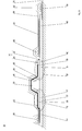
- Fig. 4 shows a first embodiment of a structure (arrangement) 18 according to the invention for producing a fibre-reinforced composite component 20.
- Composite component 20 is saturated in a single production step by resin infusion.
- Exemplary infusion techniques are resin transfer moulding (RTM), vacuum-assisted process (VAP) and vacuum resin infusion (VARI).
- Composite component 20 has two construction components 22, 24, which are embedded in a shared plastic matrix.
- Construction components or component laminates 22, 24 are dry, semi-finished textile products, made for example from carbon or glass fibres, which have been aligned appropriately for a mat, a knitted fabric, a woven fabric or similar.
- the plastic matrix consists of a matrix material or resin, which is preferably a thermosetting plastic. Of course, however, thermoplastic materials may also be used as the matrix material or resin.
- composite component 20 is the skin of an aeroplane fuselage with integrated longitudinal stiffening elements.
- lower construction component 22 represents the skin section and upper construction component 24 represents the stiffening elements.
- upper construction component 24 represents the stiffening elements.
- the composite component may also be a side shell of a tailfin, a wing shell or similar.
- composite component 20 may also be a component that is not associated with the aircraft.
- the construction component 22 that forms the skin section is in the form of a panel and is deposited on a moulded surface 26.
- Moulded surface 26 has a contour that matches an outer contour of the skin section to be formed. For purposes of clarity, moulded surface 26 is shown as being flat in design.
- the upper construction component 24 that forms the stiffening element is for example an omega stringer with two foot sections 28, 30 for securing it to lower construction component 22.
- Foot sections 28, 30 each form an overlapping area 36, 38 with the opposite body sections 32, 34.
- Control elements 40, 42 are arranged in the respective overlapping areas 36, 38 between foot sections 28, 30 and the associated body sections 32, 34. In the shown embodiment both control elements 40, 42 have the same cross section as the overlapping areas 36, 28. Upper construction component 24 is thus deposited on lower construction component 22 over membranes 40, 42.
- the control element 40 is the rear control element from the point of view of the flow direction. Its function is to decelerate a rapid front in the upper construction component 24 relative to a slow flow front in the lower construction component 22 in the overlapping area 36.
- the control element 40 is permeable to gases and therefore a membrane.
- the membrane 40 is made from a thermoplastic substance.
- the thermoplastic substance inter-diffuses with the matrix material, such that a (semi-) inter penetrating mesh (SIPN and SIPN-meshes) are established.
- SIPN and SIPN-meshes inter penetrating mesh
- a structure weakness of the composite component in the overlapping areas thus does not occur. It is permeable to gases but has only a limited permeability for the matrix material or is entirely impermeable to the matrix materialFor instance; the rear membrane 40 is a micro perforated foil.
- the control element 42 is in front with respect to the direction of flow and in one embodiment is constructed in exactly the same way and has exactly the same material characteristics as rear membrane 40. But according to another embodiment, the front control element/membrane 42 may also be highly resin-permeable. For this purpose, it may be provided with a hole pattern or a plurality of meshes through which the matrix material is able to pass with little or no resistance.
- Upper construction component 24 is positioned on lower construction component 22 in such manner that lower construction component 22 has a border area 44, 46 on each side of the overlapping areas 36, 38 that is not covered by upper construction component 24.
- the side of the upper construction component 24 facing away from lower construction component 22 is provided with an upper distribution fabric 48, which extends from a sprue 50 towards an suction device 52.
- Distribution fabric 48 is connected directly to sprue 50 and covers outer periphery of upper construction component 24 entirely or almost entirely. Starting from sprue 50, distribution fabric 48 is laid over front border area 44 of lower construction component 22 and onto front foot section 28 of upper construction component 24. It ends on rear foot section 30 and thus before rear border area 46.
- a lower distribution fabric 54 is disposed below lower construction component 22 in the area of rear border area 46, between moulded surface 26 and construction component 24, and this extends as far as suction device 52 and is this in direct operative connection therewith.
- Sprue 50 and suction device 52 are arranged on the side of composite component 20, so that this component and construction components 22, 24 are saturated transversely. They extend longitudinally with respect to construction components 22, 24 ensure that resin is supplied over the entire length thereof.
- a support core 56 is provided in order to stabilise the shape of upper construction component 24 during the resin infusion process and the subsequent autoclaving process.
- Support core 50 is inserted in a trapezoidal cavity 58 formed by construction components 22, 24 between overlapping areas 36, 38. It has a cross sectional surface that matches cavity 58 and may be a dimensionally stable solid body core, an inflatable core tube, a core tube filled with granulate or similar.
- a pressure element 60 is provided on the outer periphery to stabilise the shape and has an outer contour that replicates that of upper construction component 24 and supported on upper distribution fabric 48.
- Vacuum bag 62 is bonded in gas-tight manner to moulded surface 26, defining a vacuum chamber - without reference number - for construction components 22, 24.
- a peel ply 64 is disposed directly on top of construction components 22, 24, and the upper distribution fabric 48 is laid on top of this. Additional aids such as ventilation films may also be provided as well as peel ply 64.
- Construction components 22, 24 are arranged according to the structure 18 explained in the preceding.
- Construction components 22, 24 are evacuated via suction device 52 in the area of lower construction component 22. Then, a resin is introduced to construction components 22, 24 through the sprue 50 and the upper distribution fabric 48. A resin front is established that saturates front border area 44 of lower construction component 22. The resin front is divided into two flow fronts close to overlapping area 36, which is at the front and close to the inflow point and thus at a distance from the suction point. One flow front is formed and saturates upper construction component 24, and another flow front is formed that saturates lower construction component 22.
- front membrane 42 is only gas-permeable, and thus impermeable to resin, the resin in lower construction component 22 is only transported as far as front border area 44. But if front membrane 42 is permeable to resin, front membrane 42 does not represent a resin barrier, and the resin is conveyed to lower construction component 22 not only through front border area 44 but also via front foot section 28. In this way, the resin infusion of lower construction component 22 and thus the entire infusion process proceeds more quickly than in the process variant with a resin-impermeable front membrane 42 described in the preceding.
- upper distribution fabric 48 that is laid over upper construction component 24 means that the upper flow front has a faster flow speed than the lower flow front that must pass through lower construction component 22.
- the upper rapid flow front outstrips the lower slow flow front in the direction of flow.
- the resin-impermeable properties of membrane 40 in overlapping area 38 in the rear and close to the suction device mean that although upper construction component 24 is also evacuated through suction device 54, rear membrane 40 poses an impassable barrier for the upper flow front.
- Upper construction component 24 thus forms a cul-de-sac for the upper flowfront.
- the upper flow front cannot flow into lower construction component 22 after it has saturated upper construction component 24, so it cannot "overtake” the lower flow front, and gas inclusions in lower construction component 22 are effectively precluded.
- the upper flow front will be merged as partial flows with the lower flow front.
- the rear border area 46 After passing the rear overlapping area 38 or the overlapping area close to the suction device 52, respectively, the rear border area 46 will be saturated by the merged matrix material front.
- the structure 18 undergoes a heating process.
- energy is applied to the construction components 22, 24 in such a way that temperatures in the construction components 22, 24 are generated that are preferably higher than a melting temperature of the membranes 40, 42.
- the membranes 40, 42 and the surrounding matrix material form an adhesive bond based on inter diffusion material and do not form separating layers between construction components 22, 24 in the cured composite component 20.
- Figure 5 shows a second embodiment of the structure 18 according to the invention.
- this structure 18 has a second sprue 66 and a second upper distribution fabric 68.
- Second sprue 66 and second distribution fabric 68 are used to advantageously to the extent that the composite component 20 to be produced according to figure 5 has a more extensive rear border area 48 than the composite component as represented in figure 4 .
- the second sprue 66 and the second upper distribution fabric 68 thus serve to accelerate the resin infusion in the area of border area 46.
- Second sprue 66 is arranged downstream from rear overlapping area 38, which is close to the suction device.
- Second distribution fabric 68 is extended over the larger border area 46 and at the same time is offset laterally from rear overlapping area 38 and suction device 52. As is shown in figure 5 , second upper distribution fabric 68 preferably extends as far as a lower distribution fabric 54 in the area of suction device 52.
- Second sprue 66 is controllable and switchable independently of first sprue 50. Second sprue 66 is preferably activated as soon as the flow front flowing through the lower construction component 22 from first sprue 50 or in the case that the rear membrane 40 is limited permeable the merged matrix material front reaches it.
- the application discloses an infusion method for manufacturing a fibre-reinforced composite component, the composite component is evacuated and at least two separated flow fronts of matrix material are spread out in the composite component, wherein at least one of the flow fronts is decelerated and/or guided in respect to its flow directing relative to the other flow front by a control element that is incorporated in a component area of the composite component.
- the application also discloses a structure for performing such infusion method wherein the control element is arranged between the construction components, wherein in at least one component area a control element is incorporated in the composite component for decelerating at least one flow front and/or guiding a flow front in respect to its flow directing relative to another flow front through the composite component.
Landscapes
- Engineering & Computer Science (AREA)
- Mechanical Engineering (AREA)
- Chemical & Material Sciences (AREA)
- Composite Materials (AREA)
- Physics & Mathematics (AREA)
- Fluid Mechanics (AREA)
- General Engineering & Computer Science (AREA)
- Manufacturing & Machinery (AREA)
- Casting Or Compression Moulding Of Plastics Or The Like (AREA)
- Moulds For Moulding Plastics Or The Like (AREA)
Abstract
Description
- The invention relates to an infusion method for producing a fibre-reinforced composite component from at least two construction components, which form at least one overlapping area, according to the preamble of claim 1, and a structure for performing such an infusion method according to the preamble of
claim 6. - A schematic structure of such infusion or vacuum infusion methods is shown in
figures 1 to 3 . Acomponent 2 comprising abase laminate 4 and anadditional laminate 6 that is to be infused with a resin is placed on amoulding tool 8 and covered with adistribution fabric 10.Laminates Distribution fabric 10 serves to ensure that the resin is distributed evenly in the lengthwise and crosswise directions ofcomponent 2 and may be for example a fabric or lattice of polyester or polyamide.Component 2 anddistribution fabric 10 are packed in a vacuum bag (not shown) which is supported in sealing manner by mouldingtool 8 and is evacuated via a suction device which is also not shown. The resin is fed todistribution fabric 10 via a sprue that is not shown. According to the flow direction of the resin, indicated by the arrow, the sprue is located in an area on the left side of the component and the suction device is located in an area on the right side of the component. - When the resin is added, a
flow front 12 is formed and saturatesbase laminate 4 in a thickness direction from left to right, the resin that is closer todistribution fabric 10 advancing more quickly than the resin that is closer to mouldingtool 8, so thatflow front 12 is sloped in the thickness direction. A component and a change in the laminate thickness is present in the area ofadditional laminate 6 and, as shown infigure 2 , has the effect of preventing the resin from spreading evenly over the entire cross section ofcomponent 2, causing it to spread more slowly inbase laminate 4 that is farther from the distribution fabric than inadditional laminate 6 that is closer to the distribution fabric, so that adeflection 14 of sorts is formed inflow front 12. As a result, there is a danger that aporous area 16 may be created belowflow front 12 inbase laminate 4 afteradditional laminate 6 has been saturated, as shown infigure 3 . This is also the case when fibre semi-finished products having different permeabilities are used or geometric variations such as stringer performs, etc. are co-infused. - From the applicant's
patent application DE 10 2009 060 699 A1 , for example, it is known to alter the flow speed of the resin at least in sections within the distribution fabric. For this purpose, the distribution fabric may be furnished with sections that function as a temporary barrier for the resin, and dissolve after the adjacent resin has been prevented from advancing for certain time, so that the resin is able to continue to spread unobstructed within the distribution fabric. - It is known from US patent application
US 2003/211194 A1 to position a second distribution fabric in the area where components become thicker, via which the flow velocity is slowed in the region where the component is thicker. -
Document EP 2 149 441 A1 discloses a method for influencing the flow front of the resin by changing the flowability or the flow resistance of the resin. It is claimed that this is possible for example by altering the quantity of resin along a direction of lamination. - From
WO 2007/040797 A1 it is known to lift sections of a vacuum bag away from the component to be saturated so that the flow velocity is increased by allowing the resin to flow freely over the component. For this purpose, a solid outer housing is provided and is positioned over the vacuum bag, and a vacuum cavity for lifting the vacuum bag away from the component is defined between the housing wall and the vacuum bag. - From
EP 1 484 165 A2 it is known to monitor the progress of the flow front. For this purpose, the resin is exposed to photothermal radiation in such manner that laminate layers below the resin are thermally stimulated, so that it should be possible to determine the advance of the flow front, particularly its speed. At the same time, it is claimed, it is possible to detect air bubbles and the like. - Besides the use of distinct or separate distribution fabrics, which are placed on the component or the semi-finished goods therefor, it is also known from the applicant's
patent application DE 10 2007 013 987 A1 to integrate a distribution fabric in the surface of the mould. - The object of the invention is to provide an infusion method for manufacturing a fibre-reinforced composite component by which porous areas such as air bubbles are prevented from forming in the composite component or in the construction components thereof.
- This object is solved with an infusion method having the features of patent claim 1 and with a structure having the features of
patent claim 6. - In an infusion method according to the invention for manufacturing a fibre-reinforced composite component, the composite component is evacuated and at least two separated flow fronts of matrix material are spread out in the composite component. According to the invention at least one of the flow fronts is decelerated and/or guided in respect to its flow directing relative to the other flow front by a control element that is incorporated in a component area of the composite component.
- The control element in the at least one component area functions as a constriction for the faster flow front and/or as guiding element for the faster flow front. Both measures, which can also be combined with each other, prevents that the rapid matrix material (rapid/fast flow front) "overtakes" the slow matrix material (slow flow front) in respect to a suction device, so that the formation of porous areas such as air bubbles in the composite component are prevented as well if the flow fronts are merged. If both flow fronts have mainly the same flow velocities, for example, the control element in the at least one component area can function as a guiding element for one flow front to guide this flow front along a long path relative to a flow path of the other flow front. This measure prevents that the matrix material running the short path "overtakes" the matrix material in respect to a suction device, so that the formation of porous areas such as air bubbles in the composite component are prevented as well if the flow fronts are merged.
- In an preferred embodiment at least two construction components form at least one overlapping area as component area, wherein the control element is arranged between the construction components, and wherein the at least two flow fronts have different flow velocities in the construction components, and wherein the evacuation is performed via the construction component that is saturated with the slow flow material front. Alternatively, the at least two flow fronts have the same flow velocity in the construction components, wherein one of the flow front is guided along a long path relative to the path of the other flow front, and wherein the evacuation is performed via the construction component that is saturated with the flow front guided along the long path. If the membrane functions as a constriction for the rapid flow front, only a partial flow of the flow front can infiltrate the construction component closer to the suction device such that a flow rate of the rapid flow front will be reduced relative to the slow flow front in the overlapping area. The rapid flow front will be decelerated when reaching the control element and the slow flow front can "overtake". If the control element functions as a guiding element, the rapid flow front and one of the flow fronts, respectively, can be guided along a long path, so that the slow flow front and the other flow front, respectively, can "overtake" the flow front guided along the long path. Thus, one flow front runs a long path and one flow front runs a short path. For example, a matrix flow front is divided into two flow fronts having the same flow velocity. After one of the flow fronts is guided along a long path relative to the other flow front the flow fronts are merged.
- In one embodiment, the rapid flow front is totally prevented from saturating the construction component in which the slow flow front is spread out. This embodiment requires an apparatus that is less complex than an apparatus for just decelerating the rapid flow front, as the flow fronts are not merged and which has to be observed actually.
- Preferably an adhesive bond based on inter-diffusion between the membrane and the matrix material is established. This prevents the membrane from acting as a separating layer between the construction components. The inter-diffusion of the matrix material with the softened membrane leads to inter-penetrating or semi-inter-penetrating meshes, which establish an adhesive bond having high cohesion forces. This can be realised by using a membrane based on thermoplastic material and a matrix material based on thermoset resin, for example, assumed that material compatibility is given.
- In order to accelerate the infusion, a second sprue may be positioned between the at least one overlapping area close to the suction device and the suction device, which sprue may be activated as soon as a flow front of the matrix material from the first sprue reaches it.
- A structure/arrangement according to the invention for performing an infusion method for manufacturing a fibre-reinforced composite component has in at least one component area an incorporated control element for decelerating at least one flow front and/or guiding a flow front in respect to its flow directing relative to another flow front through the composite component.
- In a preferred embodiment the fibre-reinforced composite component has at least two construction components forming at least one overlapping area as component area, wherein at least one suction device for evacuating the composite component is positioned on the construction component in which a slow flow front compared to a flow front in the other construction component can be spread out or wherein in one component a flow front can be guided along a long path relative to the path of the flow front in the other construction component and wherein in the at least one overlapping area the control element defines at least a passage between the constriction components that is at least gas-permeable.
- For defining at least a passage that is at least gas-permeable, in a first variant the control element is a membrane that is at least highly permeable to gas-phase substances such as air. As the control element itself is gas-permeable, it can have the same cross section as the overlapping area. In a second variant, the control element is completely impermeable to gas-phase substances. In order to define the at least gas-permeable passage, in the second variant the control element has a reduced cross section compared to the cross section of the overlapping area. Due to the reduced cross sections of the control element the at least one passage is build lateral to the control element. In a third variant, the guiding element is permeable to gas-phase substances and has a reduced cross section compared to the overlapping area. Preferably, the control element or the membrane, respectively, is made from a thermoplastic material.
- In one embodiment, the control element is permeable to the matrix material. For example, the control element is a perforated foil or layer, f.i. a micro perforated foil. The holes can be implemented easily und enable a precise adjustment of the amount of matrix material that passes the control element.
- In another embodiment, the control element is permeable to gases but impermeable to the matrix material. Such a control element enables a total blockage of the rapid flow front. Thus, a merging of the separated flow fronts in the overlapping area is totally eliminated.
- In order to ensure that the slow flow front is established in the construction component close to the suction device, a distribution fabric in operative connection with the sprue may be positioned on the outer periphery of the construction component farther from the suction device.
- If multiple overlapping areas exist, the control element may be arranged in the overlapping area closest to the suction device in each case. The overlapping areas closest to the suction device are the rear overlapping areas considered in the direction of flow of the matrix material, through which the at least one construction component farther from the suction device is evacuated. In this way, the matrix material is able to flow as far as the respective control element, and gas inclusions are prevented in the at least one upper construction component.
- In order to ensure that the construction components are bonded evenly in the overlapping areas, in the case of multiple overlapping areas control elements may also be arranged in the overlapping areas farther from the suction device.
- Since, in contrast to the control element in the area closest to the suction device or the front overlapping area, the control element in the respective area farthest from the suction device or the front overlapping area does not have to perform a control function (decelerating or guiding) with regard to the construction components in which the rapid flow front is established, the respective front control element may be created so as to be permeable to the matrix material. For example, the control elements in the overlapping areas farthest from the suction device are provided with a hole pattern or a plurality of meshes to allow the matrix material to pass through with little or no obstruction.
- In order to accelerate the infusion, at least one further sprue may be included, which may be activated independently of the first sprue and is located in the area of the construction component in which the slow flow front is established. The position of this at least second sprue may be alternated between an overlapping area closer to and farther away from the suction device, in the area of the construction component in which the slow flow front is established. Alternatively or additionally, the at least one additional sprue may be positioned directly opposite the suction device, or between an overlapping area closest to the suction device and the suction device itself.
- In order to accelerate the infusion further, the second sprue may be in operative connection with a second distribution fabric which extends in the direction of suction.
- Further advantageous embodiments of the invention are the object of the additional dependent claims.
- In the following, preferred embodiments of the invention will be explained in greater detail with reference to diagrammatic representations. These show:
- Fig. 1 to Fig. 3
- a know structure and process steps in a known infusion process,
- Fig. 4
- a first embodiment of a structure according to the invention for an infusion process according to the invention, and
- Fig. 5
- a second embodiment of the structure according to the invention.
- In
figures 4 and5 , the same elements are designated by the same reference numbers. -
Fig. 4 shows a first embodiment of a structure (arrangement) 18 according to the invention for producing a fibre-reinforcedcomposite component 20.Composite component 20 is saturated in a single production step by resin infusion. Exemplary infusion techniques are resin transfer moulding (RTM), vacuum-assisted process (VAP) and vacuum resin infusion (VARI).Composite component 20 has twoconstruction components component laminates - For example,
composite component 20 is the skin of an aeroplane fuselage with integrated longitudinal stiffening elements. As shown infigure 3 ,lower construction component 22 represents the skin section andupper construction component 24 represents the stiffening elements. For the sake of easier understanding, only one stiffening element is shown and thus only oneupper construction component 24. Of course the composite component may also be a side shell of a tailfin, a wing shell or similar. In particular,composite component 20 may also be a component that is not associated with the aircraft. - The
construction component 22 that forms the skin section is in the form of a panel and is deposited on a mouldedsurface 26. Mouldedsurface 26 has a contour that matches an outer contour of the skin section to be formed. For purposes of clarity, mouldedsurface 26 is shown as being flat in design. - The
upper construction component 24 that forms the stiffening element is for example an omega stringer with twofoot sections construction component 22.Foot sections area opposite body sections -
Control elements areas foot sections body sections control elements areas Upper construction component 24 is thus deposited onlower construction component 22 overmembranes - The
control element 40 is the rear control element from the point of view of the flow direction. Its function is to decelerate a rapid front in theupper construction component 24 relative to a slow flow front in thelower construction component 22 in the overlappingarea 36. Thecontrol element 40 is permeable to gases and therefore a membrane. Preferable themembrane 40 is made from a thermoplastic substance. The thermoplastic substance inter-diffuses with the matrix material, such that a (semi-) inter penetrating mesh (SIPN and SIPN-meshes) are established. A structure weakness of the composite component in the overlapping areas thus does not occur. It is permeable to gases but has only a limited permeability for the matrix material or is entirely impermeable to the matrix materialFor instance; therear membrane 40 is a micro perforated foil. - The
control element 42 is in front with respect to the direction of flow and in one embodiment is constructed in exactly the same way and has exactly the same material characteristics asrear membrane 40. But according to another embodiment, the front control element/membrane 42 may also be highly resin-permeable. For this purpose, it may be provided with a hole pattern or a plurality of meshes through which the matrix material is able to pass with little or no resistance. -
Upper construction component 24 is positioned onlower construction component 22 in such manner thatlower construction component 22 has aborder area areas upper construction component 24. - The side of the
upper construction component 24 facing away fromlower construction component 22 is provided with anupper distribution fabric 48, which extends from asprue 50 towards ansuction device 52.Distribution fabric 48 is connected directly tosprue 50 and covers outer periphery ofupper construction component 24 entirely or almost entirely. Starting fromsprue 50,distribution fabric 48 is laid overfront border area 44 oflower construction component 22 and ontofront foot section 28 ofupper construction component 24. It ends onrear foot section 30 and thus beforerear border area 46. However, alower distribution fabric 54 is disposed belowlower construction component 22 in the area ofrear border area 46, between mouldedsurface 26 andconstruction component 24, and this extends as far assuction device 52 and is this in direct operative connection therewith. -
Sprue 50 andsuction device 52 are arranged on the side ofcomposite component 20, so that this component andconstruction components construction components - A
support core 56 is provided in order to stabilise the shape ofupper construction component 24 during the resin infusion process and the subsequent autoclaving process.Support core 50 is inserted in atrapezoidal cavity 58 formed byconstruction components areas cavity 58 and may be a dimensionally stable solid body core, an inflatable core tube, a core tube filled with granulate or similar. Apressure element 60 is provided on the outer periphery to stabilise the shape and has an outer contour that replicates that ofupper construction component 24 and supported onupper distribution fabric 48. - The
entire structure 18 is packed in avacuum bag 62.Vacuum bag 62 is bonded in gas-tight manner to mouldedsurface 26, defining a vacuum chamber - without reference number - forconstruction components - In order to prevent
upper distribution fabric 48 andvacuum bag 62 from becoming stuck during the resin infusion and the autoclaving process, apeel ply 64 is disposed directly on top ofconstruction components upper distribution fabric 48 is laid on top of this. Additional aids such as ventilation films may also be provided as well as peel ply 64. - In the following, a method according to the invention for manufacturing a
composite fibre component 20 having at least twoconstruction components Construction components structure 18 explained in the preceding. -
Construction components suction device 52 in the area oflower construction component 22. Then, a resin is introduced toconstruction components sprue 50 and theupper distribution fabric 48. A resin front is established that saturatesfront border area 44 oflower construction component 22. The resin front is divided into two flow fronts close to overlappingarea 36, which is at the front and close to the inflow point and thus at a distance from the suction point. One flow front is formed and saturatesupper construction component 24, and another flow front is formed that saturateslower construction component 22. - If
front membrane 42 is only gas-permeable, and thus impermeable to resin, the resin inlower construction component 22 is only transported as far asfront border area 44. But iffront membrane 42 is permeable to resin,front membrane 42 does not represent a resin barrier, and the resin is conveyed tolower construction component 22 not only throughfront border area 44 but also viafront foot section 28. In this way, the resin infusion oflower construction component 22 and thus the entire infusion process proceeds more quickly than in the process variant with a resin-impermeable front membrane 42 described in the preceding. - The application of
upper distribution fabric 48 that is laid overupper construction component 24 means that the upper flow front has a faster flow speed than the lower flow front that must pass throughlower construction component 22. As a result, the upper rapid flow front outstrips the lower slow flow front in the direction of flow. However, according to this embodiment, the resin-impermeable properties ofmembrane 40 in overlappingarea 38 in the rear and close to the suction device mean that althoughupper construction component 24 is also evacuated throughsuction device 54,rear membrane 40 poses an impassable barrier for the upper flow front.Upper construction component 24 thus forms a cul-de-sac for the upper flowfront. The upper flow front cannot flow intolower construction component 22 after it has saturatedupper construction component 24, so it cannot "overtake" the lower flow front, and gas inclusions inlower construction component 22 are effectively precluded. - When the
rear membrane 40 has only a limited permeability to the matrix material, the upper flow front will be merged as partial flows with the lower flow front. After passing the rear overlappingarea 38 or the overlapping area close to thesuction device 52, respectively, therear border area 46 will be saturated by the merged matrix material front. - After passing rear overlapping
area 38 close to the suction device, the lower flow front saturatesrear border area 46. - After
construction components structure 18 undergoes a heating process. In the heating process, energy is applied to theconstruction components construction components membranes membranes construction components composite component 20. -
Figure 5 shows a second embodiment of thestructure 18 according to the invention. Unlike the first structure as shown infigure 4 , thisstructure 18 has asecond sprue 66 and a secondupper distribution fabric 68.Second sprue 66 andsecond distribution fabric 68 are used to advantageously to the extent that thecomposite component 20 to be produced according tofigure 5 has a more extensiverear border area 48 than the composite component as represented infigure 4 . Thesecond sprue 66 and the secondupper distribution fabric 68 thus serve to accelerate the resin infusion in the area ofborder area 46.Second sprue 66 is arranged downstream from rear overlappingarea 38, which is close to the suction device.Second distribution fabric 68 is extended over thelarger border area 46 and at the same time is offset laterally from rear overlappingarea 38 andsuction device 52. As is shown infigure 5 , secondupper distribution fabric 68 preferably extends as far as alower distribution fabric 54 in the area ofsuction device 52. -
Second sprue 66 is controllable and switchable independently offirst sprue 50.Second sprue 66 is preferably activated as soon as the flow front flowing through thelower construction component 22 fromfirst sprue 50 or in the case that therear membrane 40 is limited permeable the merged matrix material front reaches it. - The application discloses an infusion method for manufacturing a fibre-reinforced composite component, the composite component is evacuated and at least two separated flow fronts of matrix material are spread out in the composite component, wherein at least one of the flow fronts is decelerated and/or guided in respect to its flow directing relative to the other flow front by a control element that is incorporated in a component area of the composite component. The application also discloses a structure for performing such infusion method wherein the control element is arranged between the construction components, wherein in at least one component area a control element is incorporated in the composite component for decelerating at least one flow front and/or guiding a flow front in respect to its flow directing relative to another flow front through the composite component.
-
- 2
- Component
- 4
- Base laminate
- 6
- Additional laminate
- 8
- Moulding tool
- 10
- Distribution fabric
- 12
- Flow front
- 14
- Deflection
- 16
- Porous area
- 18
- Structure/Arrangement
- 20
- Composite component
- 22
- Construction component
- 24
- Construction component
- 26
- Moulded surface
- 28
- Foot section
- 30
- Foot section
- 32
- Body section
- 34
- Body section
- 36
- Overlapping area
- 38
- Overlapping area
- 40
- Control element (rear membrane)
- 42
- Control element (front membrane)
- 44
- Border area
- 46
- Border area
- 48
- Upper distribution fabric
- 50
- Sprue
- 52
- Suction device
- 54
- Lower distribution fabric
- 56
- Support core
- 58
- Cavity
- 60
- Pressure element
- 62
- Vacuum bag
- 64
- Peel ply
- 66
- Second sprue
- 68
- Second distribution fabric
Claims (15)
- An infusion method for manufacturing a fibre-reinforced composite component (20), wherein the composite component (20) is evacuated and at least two separated flow fronts of matrix material are spread out in the composite component (20) characterized in that at least one of the flow fronts is decelerated and/or guided in respect to its flow directing relative to the other flow front by a control element (40, 42) that is incorporated in a component area (36, 38) of the composite component (20).
- An infusion method according to claim 1, wherein the composite component (20) is formed from at least two construction components (22, 24), which form at least one overlapping area as component area (36, 38), and the at least two flow fronts have different flow velocities in the construction components, and wherein the evacuation is performed via the construction component (22) that is saturated with the slow flow front or the at least two flow fronts have the same flow velocity in the construction components, wherein one of the flow front is guided along a long path relative to the path of the other flow front, and wherein the evacuation is performed via the construction component that is saturated with the flow front guided along the long path.
- The infusion method according to claim 2, wherein the rapid flow front is totally prevented from saturating the construction component (22) in which the slow flow front is spread out.
- The infusion method according to claim 2 or 3, wherein an adhesive bond based on inter-diffusion between the membrane (40, 42) and the matrix material is established.
- The infusion method according to claim 2, 3 or 4, wherein a second sprue (66) is positioned between the overlapping area (38) close to the suction device and the suction device (52) itself, which sprue is activated as soon as it is reached by a matrix material flow front from the first sprue (50).
- A structure (18) for performing an infusion method for manufacturing a fibre-reinforced composite component (20), characterized in that in at least in one component area (34, 36) a control element (40, 42) is incorporated in the composite component (20) for decelerating at least one flow front and/or guiding a flow front in respect to its flow directing relative to another flow front through the composite component (20).
- A structure (18) according to claim 6, whereby the fibre-reinforced composite component (20) has at least two construction components (22, 24) that form at least one overlapping area as a component area (36, 38), wherein at least one suction device (52) for evacuating the composite component (20) is provided, wherein in one component (36, 38) a slow flow front compared to a flow front in the other construction component (38, 36) can be spread out or wherein in one component (36, 38) a flow front can be guided along a long path relative to the path of the flow front in the other construction component (38, 36), and wherein in the at least one overlapping area the control element (40) defines at least one passage between the constriction components that is at least gas-permeable.
- The structure according to claim 6 or 7, wherein the control element (40) is permeable to the matrix material.
- The structure according to claim 6 or 7, wherein the control element (40) is impermeable to the matrix material.
- The structure according to any of the claims 6 to 9, wherein the outer periphery of the at least one construction component (24) farthest from the suction device is covered with a distribution fabric (48) that is in operative connection with an sprue (50).
- The structure according to any of the claims 6 to 10, wherein in the case of multiple overlapping areas (36, 38) the control element (40) is arranged in the overlapping area (38) close to the suction device in each case.
- The structure according to claim 11, wherein control elements (42) are arranged in overlapping areas (36) distant from the suction device.
- The structure according to claim 12, wherein the control elements (42) in the overlapping areas (36) distant from the suction device are permeable to the matrix material.
- The structure according to any of claims 6 to 13, wherein at least one further sprue (66) is provided and can be activated independently from the first sprue (50) and is arranged in the area of the construction component (22, 24) that is saturated more slowly by the matrix material.
- The structure according to claim 14, wherein the second sprue (66) is in effective connection with a second distribution fabric, which extends towards the suction device (52).
Priority Applications (2)
| Application Number | Priority Date | Filing Date | Title |
|---|---|---|---|
| EP12181596.3A EP2700492B1 (en) | 2012-08-23 | 2012-08-23 | Infusion method and structure for infusion method |
| US13/968,029 US20140053936A1 (en) | 2012-08-23 | 2013-08-15 | Infusion method and structure for infusion method |
Applications Claiming Priority (1)
| Application Number | Priority Date | Filing Date | Title |
|---|---|---|---|
| EP12181596.3A EP2700492B1 (en) | 2012-08-23 | 2012-08-23 | Infusion method and structure for infusion method |
Publications (2)
| Publication Number | Publication Date |
|---|---|
| EP2700492A1 true EP2700492A1 (en) | 2014-02-26 |
| EP2700492B1 EP2700492B1 (en) | 2017-02-01 |
Family
ID=46750229
Family Applications (1)
| Application Number | Title | Priority Date | Filing Date |
|---|---|---|---|
| EP12181596.3A Not-in-force EP2700492B1 (en) | 2012-08-23 | 2012-08-23 | Infusion method and structure for infusion method |
Country Status (2)
| Country | Link |
|---|---|
| US (1) | US20140053936A1 (en) |
| EP (1) | EP2700492B1 (en) |
Families Citing this family (2)
| Publication number | Priority date | Publication date | Assignee | Title |
|---|---|---|---|---|
| EP3521002B1 (en) * | 2016-09-29 | 2023-11-01 | Subaru Corporation | Composite material structure and method for manufacturing composite material structure |
| CN116619781B (en) * | 2023-07-25 | 2023-10-31 | 北京理工大学 | Three-vacuum-bag filling forming device and forming method |
Citations (8)
| Publication number | Priority date | Publication date | Assignee | Title |
|---|---|---|---|---|
| US20030211194A1 (en) | 2002-04-23 | 2003-11-13 | Michael Louderback | High-performance infusion system for VARTM fabrication |
| EP1484165A2 (en) | 2003-06-02 | 2004-12-08 | Deutsches Zentrum für Luft- und Raumfahrt e.V. | Method for monitoring the manufacture of a fibre reinforced moulded part |
| WO2007040797A2 (en) | 2005-09-22 | 2007-04-12 | University Of Delaware | Vacuum assisted resin transfer molding techniques with flow flooding chamber |
| DE102007013987A1 (en) | 2006-08-17 | 2008-02-21 | Airbus Deutschland Gmbh | Molding surface used when making fibrous composite components in aerospace industry, includes diversity of groove types for supply of impregnation material to fibrous blank |
| WO2009003477A1 (en) * | 2007-06-29 | 2009-01-08 | Lm Glasfiber A/S | A method for producing a composite structure and a composite structure |
| EP2149441A1 (en) | 2007-03-20 | 2010-02-03 | Mitsubishi Heavy Industries, Ltd. | Method of vacuum-assisted rtm |
| DE102009060699A1 (en) | 2009-12-29 | 2011-06-30 | Airbus Operations GmbH, 21129 | Infusion method and flow aid |
| WO2012026980A2 (en) * | 2010-08-23 | 2012-03-01 | Materia, Inc. | Vartm flow modifications for low viscosity resin systems |
Family Cites Families (16)
| Publication number | Priority date | Publication date | Assignee | Title |
|---|---|---|---|---|
| US2913036A (en) * | 1956-08-10 | 1959-11-17 | Anthony Bros Fibre Glass Pool | Process and apparatus for molding large plastic structures |
| FR2605929B1 (en) * | 1986-11-05 | 1989-03-31 | Brochier Sa | TEXTILE MATERIAL FOR PRODUCING LAMINATED ARTICLES REINFORCED BY INJECTION MOLDING |
| US4942013A (en) * | 1989-03-27 | 1990-07-17 | Mcdonnell Douglas Corporation | Vacuum resin impregnation process |
| US6048488A (en) * | 1997-04-04 | 2000-04-11 | The United States Of America As Represented By The Secretary Of The Army | One-step resin transfer molding of multifunctional composites consisting of multiple resins |
| US6818159B2 (en) * | 2000-03-17 | 2004-11-16 | Deutsches Zentrum Fuer Luft-Und Raumfahrt E.V. | Process for the production of a composite consisting of a fiber reinforced material |
| DE10013409C1 (en) * | 2000-03-17 | 2000-11-23 | Daimler Chrysler Ag | Vacuum injection process for manufacturing fiber reinforced composite products involves evacuating second chamber causing resin to flow into preform in adjacent evacuated first chamber |
| GB0229094D0 (en) * | 2002-12-13 | 2003-01-15 | Hexcel Composites Ltd | Improvements in or relating to the preparation of fibre-reinforced composites |
| US20040219855A1 (en) * | 2003-05-02 | 2004-11-04 | Tsotsis Thomas K. | Highly porous interlayers to toughen liquid-molded fabric-based composites |
| US20050037678A1 (en) * | 2003-08-11 | 2005-02-17 | Mack Patrick E. | Open grid fabric resin infusion media and reinforcing composite lamina |
| DK176150B1 (en) * | 2004-11-30 | 2006-10-16 | Lm Glasfiber As | Method and apparatus for preparing fiber composite blanks by vacuum infusion |
| WO2006121961A1 (en) * | 2005-05-09 | 2006-11-16 | Cytec Technology Corp. | Resin-soluble thermoplastic veil for composite materials |
| US7595112B1 (en) * | 2006-07-31 | 2009-09-29 | The United States Of America As Represented By The Administrator Of The National Aeronautics And Space Administration | Resin infusion of layered metal/composite hybrid and resulting metal/composite hybrid laminate |
| GB0702781D0 (en) * | 2007-02-13 | 2007-03-21 | Airbus Uk Ltd | Method of processing a composite material |
| US8945450B2 (en) * | 2009-11-04 | 2015-02-03 | Mitsubishi Heavy Industries, Ltd. | Apparatus and method for manufacturing fiber reinforced plastic structure |
| US9132591B2 (en) * | 2010-07-02 | 2015-09-15 | Hexcel Holding Gmbh | Fibre reinforced composite moulding |
| JP5533743B2 (en) * | 2010-09-24 | 2014-06-25 | 東レ株式会社 | Manufacturing method of fiber reinforced plastic |
-
2012
- 2012-08-23 EP EP12181596.3A patent/EP2700492B1/en not_active Not-in-force
-
2013
- 2013-08-15 US US13/968,029 patent/US20140053936A1/en not_active Abandoned
Patent Citations (8)
| Publication number | Priority date | Publication date | Assignee | Title |
|---|---|---|---|---|
| US20030211194A1 (en) | 2002-04-23 | 2003-11-13 | Michael Louderback | High-performance infusion system for VARTM fabrication |
| EP1484165A2 (en) | 2003-06-02 | 2004-12-08 | Deutsches Zentrum für Luft- und Raumfahrt e.V. | Method for monitoring the manufacture of a fibre reinforced moulded part |
| WO2007040797A2 (en) | 2005-09-22 | 2007-04-12 | University Of Delaware | Vacuum assisted resin transfer molding techniques with flow flooding chamber |
| DE102007013987A1 (en) | 2006-08-17 | 2008-02-21 | Airbus Deutschland Gmbh | Molding surface used when making fibrous composite components in aerospace industry, includes diversity of groove types for supply of impregnation material to fibrous blank |
| EP2149441A1 (en) | 2007-03-20 | 2010-02-03 | Mitsubishi Heavy Industries, Ltd. | Method of vacuum-assisted rtm |
| WO2009003477A1 (en) * | 2007-06-29 | 2009-01-08 | Lm Glasfiber A/S | A method for producing a composite structure and a composite structure |
| DE102009060699A1 (en) | 2009-12-29 | 2011-06-30 | Airbus Operations GmbH, 21129 | Infusion method and flow aid |
| WO2012026980A2 (en) * | 2010-08-23 | 2012-03-01 | Materia, Inc. | Vartm flow modifications for low viscosity resin systems |
Non-Patent Citations (1)
| Title |
|---|
| MIRACLE & S L DONALDSON D B ED - MIRACLE & S L DONALDSON D B: "Composites, Vacuum Infusion", 1 December 2001, ASM HANDBOOK / PREPARED UNDER THE DIRECTION OF THE ASM INTERNATIONAL HANDBOOK COMMITTEE, ASM INTERNATIONAL, MATERIALS PARK, OHIO ,USA, PAGE(S) 501 - 511, ISBN: 978-0-87170-703-1, XP002619563 * |
Also Published As
| Publication number | Publication date |
|---|---|
| EP2700492B1 (en) | 2017-02-01 |
| US20140053936A1 (en) | 2014-02-27 |
Similar Documents
| Publication | Publication Date | Title |
|---|---|---|
| CN101394990B (en) | Method and apparatus for providing polymers for vacuum infusion | |
| DK2647492T3 (en) | Resinstrømelement to a vacuum assisted resinoverførselsstøbeproces | |
| EP2222453B1 (en) | A method of manufacturing a composite part from resin-preimpregnated fibres | |
| CN100553955C (en) | Vacuum impregnation using semi-permeable membranes | |
| CN103963316B (en) | Pressure Sensitive Flow Dispense Media for VARTM | |
| US9156208B2 (en) | Infusion method and flow aid | |
| JP2009528195A5 (en) | ||
| US20160136905A1 (en) | Flow aid for infusion structure, infusion structure comprising a flow aid and method for infiltrating fibre material with resin | |
| EP2535171B1 (en) | Method of manufacturing an oblong shell part and such shell part | |
| JP6758385B2 (en) | Manufacturing method of fiber reinforced plastic molded products | |
| EP2700492B1 (en) | Infusion method and structure for infusion method | |
| CN107791541B (en) | Method for locally influencing the resin permeability of a dry preform | |
| CN107645984B (en) | Actuating surface element | |
| EP3266595B1 (en) | Method and system for resin infusing a composite preform | |
| KR102090632B1 (en) | Molding device of fiber-reinforced composite material by VARTM process and molding method of fiber-reinforced composite material thereby | |
| WO2012082778A2 (en) | Composite article and method of manufacture |
Legal Events
| Date | Code | Title | Description |
|---|---|---|---|
| PUAI | Public reference made under article 153(3) epc to a published international application that has entered the european phase |
Free format text: ORIGINAL CODE: 0009012 |
|
| AK | Designated contracting states |
Kind code of ref document: A1 Designated state(s): AL AT BE BG CH CY CZ DE DK EE ES FI FR GB GR HR HU IE IS IT LI LT LU LV MC MK MT NL NO PL PT RO RS SE SI SK SM TR |
|
| AX | Request for extension of the european patent |
Extension state: BA ME |
|
| 17P | Request for examination filed |
Effective date: 20140825 |
|
| RBV | Designated contracting states (corrected) |
Designated state(s): AL AT BE BG CH CY CZ DE DK EE ES FI FR GB GR HR HU IE IS IT LI LT LU LV MC MK MT NL NO PL PT RO RS SE SI SK SM TR |
|
| 17Q | First examination report despatched |
Effective date: 20151021 |
|
| GRAP | Despatch of communication of intention to grant a patent |
Free format text: ORIGINAL CODE: EPIDOSNIGR1 |
|
| INTG | Intention to grant announced |
Effective date: 20161013 |
|
| GRAS | Grant fee paid |
Free format text: ORIGINAL CODE: EPIDOSNIGR3 |
|
| STAA | Information on the status of an ep patent application or granted ep patent |
Free format text: STATUS: GRANT OF PATENT IS INTENDED |
|
| GRAA | (expected) grant |
Free format text: ORIGINAL CODE: 0009210 |
|
| STAA | Information on the status of an ep patent application or granted ep patent |
Free format text: STATUS: THE PATENT HAS BEEN GRANTED |
|
| AK | Designated contracting states |
Kind code of ref document: B1 Designated state(s): AL AT BE BG CH CY CZ DE DK EE ES FI FR GB GR HR HU IE IS IT LI LT LU LV MC MK MT NL NO PL PT RO RS SE SI SK SM TR |
|
| REG | Reference to a national code |
Ref country code: GB Ref legal event code: FG4D |
|
| REG | Reference to a national code |
Ref country code: CH Ref legal event code: EP Ref country code: AT Ref legal event code: REF Ref document number: 865196 Country of ref document: AT Kind code of ref document: T Effective date: 20170215 |
|
| REG | Reference to a national code |
Ref country code: IE Ref legal event code: FG4D |
|
| REG | Reference to a national code |
Ref country code: DE Ref legal event code: R096 Ref document number: 602012028181 Country of ref document: DE |
|
| REG | Reference to a national code |
Ref country code: NL Ref legal event code: MP Effective date: 20170201 |
|
| REG | Reference to a national code |
Ref country code: LT Ref legal event code: MG4D |
|
| REG | Reference to a national code |
Ref country code: AT Ref legal event code: MK05 Ref document number: 865196 Country of ref document: AT Kind code of ref document: T Effective date: 20170201 |
|
| PG25 | Lapsed in a contracting state [announced via postgrant information from national office to epo] |
Ref country code: FI Free format text: LAPSE BECAUSE OF FAILURE TO SUBMIT A TRANSLATION OF THE DESCRIPTION OR TO PAY THE FEE WITHIN THE PRESCRIBED TIME-LIMIT Effective date: 20170201 Ref country code: GR Free format text: LAPSE BECAUSE OF FAILURE TO SUBMIT A TRANSLATION OF THE DESCRIPTION OR TO PAY THE FEE WITHIN THE PRESCRIBED TIME-LIMIT Effective date: 20170502 Ref country code: HR Free format text: LAPSE BECAUSE OF FAILURE TO SUBMIT A TRANSLATION OF THE DESCRIPTION OR TO PAY THE FEE WITHIN THE PRESCRIBED TIME-LIMIT Effective date: 20170201 Ref country code: LT Free format text: LAPSE BECAUSE OF FAILURE TO SUBMIT A TRANSLATION OF THE DESCRIPTION OR TO PAY THE FEE WITHIN THE PRESCRIBED TIME-LIMIT Effective date: 20170201 Ref country code: IS Free format text: LAPSE BECAUSE OF FAILURE TO SUBMIT A TRANSLATION OF THE DESCRIPTION OR TO PAY THE FEE WITHIN THE PRESCRIBED TIME-LIMIT Effective date: 20170601 Ref country code: NO Free format text: LAPSE BECAUSE OF FAILURE TO SUBMIT A TRANSLATION OF THE DESCRIPTION OR TO PAY THE FEE WITHIN THE PRESCRIBED TIME-LIMIT Effective date: 20170501 |
|
| REG | Reference to a national code |
Ref country code: FR Ref legal event code: PLFP Year of fee payment: 6 |
|
| PG25 | Lapsed in a contracting state [announced via postgrant information from national office to epo] |
Ref country code: NL Free format text: LAPSE BECAUSE OF FAILURE TO SUBMIT A TRANSLATION OF THE DESCRIPTION OR TO PAY THE FEE WITHIN THE PRESCRIBED TIME-LIMIT Effective date: 20170201 Ref country code: PL Free format text: LAPSE BECAUSE OF FAILURE TO SUBMIT A TRANSLATION OF THE DESCRIPTION OR TO PAY THE FEE WITHIN THE PRESCRIBED TIME-LIMIT Effective date: 20170201 Ref country code: SE Free format text: LAPSE BECAUSE OF FAILURE TO SUBMIT A TRANSLATION OF THE DESCRIPTION OR TO PAY THE FEE WITHIN THE PRESCRIBED TIME-LIMIT Effective date: 20170201 Ref country code: LV Free format text: LAPSE BECAUSE OF FAILURE TO SUBMIT A TRANSLATION OF THE DESCRIPTION OR TO PAY THE FEE WITHIN THE PRESCRIBED TIME-LIMIT Effective date: 20170201 Ref country code: PT Free format text: LAPSE BECAUSE OF FAILURE TO SUBMIT A TRANSLATION OF THE DESCRIPTION OR TO PAY THE FEE WITHIN THE PRESCRIBED TIME-LIMIT Effective date: 20170601 Ref country code: AT Free format text: LAPSE BECAUSE OF FAILURE TO SUBMIT A TRANSLATION OF THE DESCRIPTION OR TO PAY THE FEE WITHIN THE PRESCRIBED TIME-LIMIT Effective date: 20170201 Ref country code: BG Free format text: LAPSE BECAUSE OF FAILURE TO SUBMIT A TRANSLATION OF THE DESCRIPTION OR TO PAY THE FEE WITHIN THE PRESCRIBED TIME-LIMIT Effective date: 20170501 Ref country code: RS Free format text: LAPSE BECAUSE OF FAILURE TO SUBMIT A TRANSLATION OF THE DESCRIPTION OR TO PAY THE FEE WITHIN THE PRESCRIBED TIME-LIMIT Effective date: 20170201 Ref country code: ES Free format text: LAPSE BECAUSE OF FAILURE TO SUBMIT A TRANSLATION OF THE DESCRIPTION OR TO PAY THE FEE WITHIN THE PRESCRIBED TIME-LIMIT Effective date: 20170201 |
|
| PG25 | Lapsed in a contracting state [announced via postgrant information from national office to epo] |
Ref country code: RO Free format text: LAPSE BECAUSE OF FAILURE TO SUBMIT A TRANSLATION OF THE DESCRIPTION OR TO PAY THE FEE WITHIN THE PRESCRIBED TIME-LIMIT Effective date: 20170201 Ref country code: SK Free format text: LAPSE BECAUSE OF FAILURE TO SUBMIT A TRANSLATION OF THE DESCRIPTION OR TO PAY THE FEE WITHIN THE PRESCRIBED TIME-LIMIT Effective date: 20170201 Ref country code: CZ Free format text: LAPSE BECAUSE OF FAILURE TO SUBMIT A TRANSLATION OF THE DESCRIPTION OR TO PAY THE FEE WITHIN THE PRESCRIBED TIME-LIMIT Effective date: 20170201 Ref country code: EE Free format text: LAPSE BECAUSE OF FAILURE TO SUBMIT A TRANSLATION OF THE DESCRIPTION OR TO PAY THE FEE WITHIN THE PRESCRIBED TIME-LIMIT Effective date: 20170201 Ref country code: IT Free format text: LAPSE BECAUSE OF FAILURE TO SUBMIT A TRANSLATION OF THE DESCRIPTION OR TO PAY THE FEE WITHIN THE PRESCRIBED TIME-LIMIT Effective date: 20170201 |
|
| REG | Reference to a national code |
Ref country code: DE Ref legal event code: R097 Ref document number: 602012028181 Country of ref document: DE |
|
| PG25 | Lapsed in a contracting state [announced via postgrant information from national office to epo] |
Ref country code: SM Free format text: LAPSE BECAUSE OF FAILURE TO SUBMIT A TRANSLATION OF THE DESCRIPTION OR TO PAY THE FEE WITHIN THE PRESCRIBED TIME-LIMIT Effective date: 20170201 Ref country code: DK Free format text: LAPSE BECAUSE OF FAILURE TO SUBMIT A TRANSLATION OF THE DESCRIPTION OR TO PAY THE FEE WITHIN THE PRESCRIBED TIME-LIMIT Effective date: 20170201 |
|
| PLBE | No opposition filed within time limit |
Free format text: ORIGINAL CODE: 0009261 |
|
| STAA | Information on the status of an ep patent application or granted ep patent |
Free format text: STATUS: NO OPPOSITION FILED WITHIN TIME LIMIT |
|
| 26N | No opposition filed |
Effective date: 20171103 |
|
| PG25 | Lapsed in a contracting state [announced via postgrant information from national office to epo] |
Ref country code: SI Free format text: LAPSE BECAUSE OF FAILURE TO SUBMIT A TRANSLATION OF THE DESCRIPTION OR TO PAY THE FEE WITHIN THE PRESCRIBED TIME-LIMIT Effective date: 20170201 |
|
| REG | Reference to a national code |
Ref country code: CH Ref legal event code: PL |
|
| PG25 | Lapsed in a contracting state [announced via postgrant information from national office to epo] |
Ref country code: MC Free format text: LAPSE BECAUSE OF FAILURE TO SUBMIT A TRANSLATION OF THE DESCRIPTION OR TO PAY THE FEE WITHIN THE PRESCRIBED TIME-LIMIT Effective date: 20170201 |
|
| GBPC | Gb: european patent ceased through non-payment of renewal fee |
Effective date: 20170823 |
|
| PG25 | Lapsed in a contracting state [announced via postgrant information from national office to epo] |
Ref country code: CH Free format text: LAPSE BECAUSE OF NON-PAYMENT OF DUE FEES Effective date: 20170831 Ref country code: LI Free format text: LAPSE BECAUSE OF NON-PAYMENT OF DUE FEES Effective date: 20170831 |
|
| REG | Reference to a national code |
Ref country code: IE Ref legal event code: MM4A |
|
| REG | Reference to a national code |
Ref country code: BE Ref legal event code: MM Effective date: 20170831 |
|
| PG25 | Lapsed in a contracting state [announced via postgrant information from national office to epo] |
Ref country code: LU Free format text: LAPSE BECAUSE OF NON-PAYMENT OF DUE FEES Effective date: 20170823 |
|
| PG25 | Lapsed in a contracting state [announced via postgrant information from national office to epo] |
Ref country code: IE Free format text: LAPSE BECAUSE OF NON-PAYMENT OF DUE FEES Effective date: 20170823 Ref country code: GB Free format text: LAPSE BECAUSE OF NON-PAYMENT OF DUE FEES Effective date: 20170823 |
|
| REG | Reference to a national code |
Ref country code: FR Ref legal event code: PLFP Year of fee payment: 7 |
|
| PG25 | Lapsed in a contracting state [announced via postgrant information from national office to epo] |
Ref country code: BE Free format text: LAPSE BECAUSE OF NON-PAYMENT OF DUE FEES Effective date: 20170831 |
|
| PG25 | Lapsed in a contracting state [announced via postgrant information from national office to epo] |
Ref country code: MT Free format text: LAPSE BECAUSE OF NON-PAYMENT OF DUE FEES Effective date: 20170823 |
|
| PG25 | Lapsed in a contracting state [announced via postgrant information from national office to epo] |
Ref country code: HU Free format text: LAPSE BECAUSE OF FAILURE TO SUBMIT A TRANSLATION OF THE DESCRIPTION OR TO PAY THE FEE WITHIN THE PRESCRIBED TIME-LIMIT; INVALID AB INITIO Effective date: 20120823 |
|
| PG25 | Lapsed in a contracting state [announced via postgrant information from national office to epo] |
Ref country code: CY Free format text: LAPSE BECAUSE OF NON-PAYMENT OF DUE FEES Effective date: 20170201 |
|
| PGFP | Annual fee paid to national office [announced via postgrant information from national office to epo] |
Ref country code: FR Payment date: 20190822 Year of fee payment: 8 |
|
| PG25 | Lapsed in a contracting state [announced via postgrant information from national office to epo] |
Ref country code: MK Free format text: LAPSE BECAUSE OF FAILURE TO SUBMIT A TRANSLATION OF THE DESCRIPTION OR TO PAY THE FEE WITHIN THE PRESCRIBED TIME-LIMIT Effective date: 20170201 |
|
| PG25 | Lapsed in a contracting state [announced via postgrant information from national office to epo] |
Ref country code: TR Free format text: LAPSE BECAUSE OF FAILURE TO SUBMIT A TRANSLATION OF THE DESCRIPTION OR TO PAY THE FEE WITHIN THE PRESCRIBED TIME-LIMIT Effective date: 20170201 |
|
| PG25 | Lapsed in a contracting state [announced via postgrant information from national office to epo] |
Ref country code: AL Free format text: LAPSE BECAUSE OF FAILURE TO SUBMIT A TRANSLATION OF THE DESCRIPTION OR TO PAY THE FEE WITHIN THE PRESCRIBED TIME-LIMIT Effective date: 20170201 |
|
| PG25 | Lapsed in a contracting state [announced via postgrant information from national office to epo] |
Ref country code: FR Free format text: LAPSE BECAUSE OF NON-PAYMENT OF DUE FEES Effective date: 20200831 |
|
| PGFP | Annual fee paid to national office [announced via postgrant information from national office to epo] |
Ref country code: DE Payment date: 20210819 Year of fee payment: 10 |
|
| REG | Reference to a national code |
Ref country code: DE Ref legal event code: R119 Ref document number: 602012028181 Country of ref document: DE |
|
| PG25 | Lapsed in a contracting state [announced via postgrant information from national office to epo] |
Ref country code: DE Free format text: LAPSE BECAUSE OF NON-PAYMENT OF DUE FEES Effective date: 20230301 |