EP2699177B1 - Apparatus for sizing a connecting element for positioning along a bone structure - Google Patents
Apparatus for sizing a connecting element for positioning along a bone structure Download PDFInfo
- Publication number
- EP2699177B1 EP2699177B1 EP12774055.3A EP12774055A EP2699177B1 EP 2699177 B1 EP2699177 B1 EP 2699177B1 EP 12774055 A EP12774055 A EP 12774055A EP 2699177 B1 EP2699177 B1 EP 2699177B1
- Authority
- EP
- European Patent Office
- Prior art keywords
- arm
- bone
- bone screw
- graduated scale
- engaged
- Prior art date
- Legal status (The legal status is an assumption and is not a legal conclusion. Google has not performed a legal analysis and makes no representation as to the accuracy of the status listed.)
- Active
Links
Images



Classifications
-
- A—HUMAN NECESSITIES
- A61—MEDICAL OR VETERINARY SCIENCE; HYGIENE
- A61B—DIAGNOSIS; SURGERY; IDENTIFICATION
- A61B90/00—Instruments, implements or accessories specially adapted for surgery or diagnosis and not covered by any of the groups A61B1/00 - A61B50/00, e.g. for luxation treatment or for protecting wound edges
- A61B90/06—Measuring instruments not otherwise provided for
-
- A—HUMAN NECESSITIES
- A61—MEDICAL OR VETERINARY SCIENCE; HYGIENE
- A61B—DIAGNOSIS; SURGERY; IDENTIFICATION
- A61B17/00—Surgical instruments, devices or methods
- A61B17/56—Surgical instruments or methods for treatment of bones or joints; Devices specially adapted therefor
- A61B17/58—Surgical instruments or methods for treatment of bones or joints; Devices specially adapted therefor for osteosynthesis, e.g. bone plates, screws or setting implements
- A61B17/68—Internal fixation devices, including fasteners and spinal fixators, even if a part thereof projects from the skin
- A61B17/70—Spinal positioners or stabilisers, e.g. stabilisers comprising fluid filler in an implant
- A61B17/7074—Tools specially adapted for spinal fixation operations other than for bone removal or filler handling
- A61B17/7076—Tools specially adapted for spinal fixation operations other than for bone removal or filler handling for driving, positioning or assembling spinal clamps or bone anchors specially adapted for spinal fixation
- A61B17/7077—Tools specially adapted for spinal fixation operations other than for bone removal or filler handling for driving, positioning or assembling spinal clamps or bone anchors specially adapted for spinal fixation for moving bone anchors attached to vertebrae, thereby displacing the vertebrae
- A61B17/708—Tools specially adapted for spinal fixation operations other than for bone removal or filler handling for driving, positioning or assembling spinal clamps or bone anchors specially adapted for spinal fixation for moving bone anchors attached to vertebrae, thereby displacing the vertebrae with tubular extensions coaxially mounted on the bone anchors
-
- A—HUMAN NECESSITIES
- A61—MEDICAL OR VETERINARY SCIENCE; HYGIENE
- A61B—DIAGNOSIS; SURGERY; IDENTIFICATION
- A61B90/00—Instruments, implements or accessories specially adapted for surgery or diagnosis and not covered by any of the groups A61B1/00 - A61B50/00, e.g. for luxation treatment or for protecting wound edges
- A61B90/06—Measuring instruments not otherwise provided for
- A61B2090/061—Measuring instruments not otherwise provided for for measuring dimensions, e.g. length
-
- A—HUMAN NECESSITIES
- A61—MEDICAL OR VETERINARY SCIENCE; HYGIENE
- A61B—DIAGNOSIS; SURGERY; IDENTIFICATION
- A61B90/00—Instruments, implements or accessories specially adapted for surgery or diagnosis and not covered by any of the groups A61B1/00 - A61B50/00, e.g. for luxation treatment or for protecting wound edges
- A61B90/06—Measuring instruments not otherwise provided for
- A61B2090/067—Measuring instruments not otherwise provided for for measuring angles
-
- A—HUMAN NECESSITIES
- A61—MEDICAL OR VETERINARY SCIENCE; HYGIENE
- A61F—FILTERS IMPLANTABLE INTO BLOOD VESSELS; PROSTHESES; DEVICES PROVIDING PATENCY TO, OR PREVENTING COLLAPSING OF, TUBULAR STRUCTURES OF THE BODY, e.g. STENTS; ORTHOPAEDIC, NURSING OR CONTRACEPTIVE DEVICES; FOMENTATION; TREATMENT OR PROTECTION OF EYES OR EARS; BANDAGES, DRESSINGS OR ABSORBENT PADS; FIRST-AID KITS
- A61F2/00—Filters implantable into blood vessels; Prostheses, i.e. artificial substitutes or replacements for parts of the body; Appliances for connecting them with the body; Devices providing patency to, or preventing collapsing of, tubular structures of the body, e.g. stents
- A61F2/02—Prostheses implantable into the body
- A61F2/30—Joints
- A61F2/46—Special tools for implanting artificial joints
- A61F2/4657—Measuring instruments used for implanting artificial joints
- A61F2002/4658—Measuring instruments used for implanting artificial joints for measuring dimensions, e.g. length
Definitions
- the fracture of an elongated bone such as a femur or humerus
- a plate to the fractured bone across the fracture.
- the plate extends across the fractured area and thus stabilizes the fractured components of the bones relative to one another in a desired position.
- the plate can be removed or left in place, depending on the type of plate that is used.
- Another type of stabilization technique uses one or more elongated rods extending between components of a bone structure and secured to the bone structure to stabilize the components relative to one another.
- the components of the bone structure are exposed and one or more bone engaging fasteners are placed into each component.
- the elongated rod is then secured to the bone engaging fasteners in order to stabilize the components of the bone structure.
- One problem associated with the above described stabilization structures is that the skin and tissue surrounding the surgical site must be cut, removed, and/or repositioned in order for the surgeon to access the location where the stabilization device is to be installed. This prepositioning of tissue causes trauma, damage, and scarring to the tissue. There are also risks that the tissue will become infected and that a long recovery time will be required after surgery for the tissue to heal.
- Minimally invasive surgical techniques are particularly desirable in, for example, spinal and neurosurgical applications because of the need for access to locations within the body and the potential trauma to vital intervening tissues.
- the development of percutaneous minimally invasive spinal procedures has yielded a major improvement in reducing trauma, recovery time and post-operative pain.
- the benefits of minimally invasive techniques have also found application in surgeries for other locations in the body where it is desirable to minimize tissue disruption.
- US 2008/200919 A1 discloses a tool for determining the length of a connecting element needed to bridge between first and second fasteners mounted to first and second vertebral bodies of a vertebral body segment includes first and second engagement means mounted for translation and pivoting relative to one another.
- Indicia mounted relative to the first and second engagement means are each defined by a locus of points corresponding to a particular connecting element length and each point corresponds to one of a plurality of relative translated and angular positions of the first and second engagement means for the particular connecting element length such that the indicia and pointer indicate the connecting element length for a plurality of combinations of relative translated and angular positions of the first and second engagement means.
- an apparatus comprises a first arm having a distal end adapted to engage a first bone screw extender, and a proximal end comprising a graduated scale.
- a single pivot pin is operably engaged with the first arm between the distal end and the proximal end thereof.
- the apparatus also comprises a second arm operably engaged with the first arm via the single pivot pin.
- the second arm has a distal end adapted to engage the second bone screw extender, and a proximal end comprising an indicator segment slidably engaged with the graduated scale. Therefore, a position of the indicator segment relative to the graduated scale may be indicative of a spacing between the first and second bone screws.
- a system for percutaneous implantation of spinal instrumentation comprising a first bone screw extender adapted to implant a first bone screw at a first bone structure and a second bone screw extender adapted to implant a second bone screw at a second bone structure.
- a caliper is also provided for measuring spacing between first and second bone screws engaged with first and second bone structures, wherein the caliper comprises a first arm having a distal end adapted to engage the first bone screw extender, and a proximal end comprising a graduated scale extending therefrom.
- the caliper also comprises a single pivot pin operably engaged with the first arm between the distal end and the proximal end thereof, and a second arm operably engaged with the first arm via the single pivot pin, the second arm having a distal end adapted to engage the second bone screw extender, and a proximal end comprising an indicator segment slidably engaged with the graduated scale of the first arm.
- a position of the indicator segment relative to the graduated scale may therefore be indicative of the spacing between the first and second bone screws, allowing a surgeon to accurately determine a length of spinal rod to be inserted to connect the first and second bone screws.
- a method for measuring spacing between first and second bone screws engaged with first and second bone structures is described.
- the method comprises engaging a first bone screw extender with the first bone screw, engaging a second bone screw extender with the second bone screw, and pivoting a first arm and a second arm of a caliper relative to one another about a single pivot pin operably engaged with the first and second arms, such that the first and second arms of the caliper are insertable into the first and second bone screw extenders.
- the method further comprises inserting the first arm of the caliper into the first bone screw extender, wherein the first arm has a distal end configured to engage the first bone screw extender, and a proximal end comprising a graduated scale extending therefrom.
- the method further comprises inserting the second arm of the caliper in the second bone screw extender, wherein the second arm has a distal end configured to engage the second bone screw extender, and a proximal end comprising an indicator segment slidably engaged with the graduated scale of the first arm. Therefore, a position of the indicator segment relative to the graduated scale may be indicative of a spacing between the first and second bone screws.
- apparatus and an exemplary method is provided for measuring spacing between first and second bone screws P1, P2 engaged with first and second bone structures V1, V2.
- an apparatus such as a caliper 1
- a surgeon may wish to accurately measure and/or estimate the spacing S between adjacent first and second bone screws P1, P2 in a spinal surgery such that a spinal rod R having an appropriate length may be chosen from a plurality of spinal rod R sizes to connect adjacent first and second bone screws P1, P2.
- a surgeon may seek to estimate the length of spinal rod R that should be implanted using a minimally-invasive rod insertion technique such as that offered by the CD Horizon® LongitudeTM Multi-level Percutaneous Fixation System developed by Medtronic Spinal and Biologics, of Memphis Tennessee.
- the various embodiments described herein provide exemplary caliper 1 apparatus for accurately measuring the spacing S between adjacent first and second bone screws P1, P2 engaged with bone screw extenders 40, 50 such that a surgeon may be better informed when selecting spinal rod R components when performing spinal procedures.
- exemplary caliper 1 apparatus and related methods described herein may include a caliper 1 that is sized and/or calibrated to measure spacing S between adjacent bone screws P1, P2 without the use of intervening bone screw extenders 40, 50 (such as in "open” or non-percutaneous surgical procedures).
- a caliper 1 may comprise a first arm 10 having a distal end 12 adapted to engage the first bone screw P1 (according to the present invention, via the bone screw extender 40, as shown in Figure 4 ).
- the first arm 10 also comprises a proximal end 16 comprising a graduated scale 15 extending therefrom.
- the caliper 1 further comprises a single pivot pin 30 operably engaged with the first arm 10 between the distal end 12 and the proximal end 16 thereof.
- the caliper 1 further comprises a second arm 20 operably engaged with the first arm 10 via the single pivot pin 30.
- the second arm 20 also has a distal end 22 adapted to engage the second bone screw P2 (according to the present invention, via the bone screw extender 50, as shown in Figure 4 ), and a proximal end 26 comprising an indicator segment 25 slidably engaged with the graduated scale 15 such that a position of the indicator segment 25 relative to the graduated scale 15 is indicative of a spacing S between the first and second bone screws P1, P2 (see Figure 3 , for example, where the spacing S is shown between distal ends 41, 51 of the bone screw extenders 40, 50, respectively).
- the distal ends of the first and second arms 10, 20 comprise cylindrical elements 12, 22 configured to be insertable into a first bone screw extender 40 and a second bone screw extender 50 (see Figure 3 , for example) extending respectively from the first and second bone screws P1, P2 (see Figure 5 , for example).
- the distal ends of the first and second arms 10, 20 also comprise stop elements 11,21 formed thereon that may ensure that the cylindrical elements 12, 22 extend only a selected distance into a complementary set of cylindrical bores defined in the bone screw extenders 40, 50.
- the extreme distal ends of the cylindrical elements 12, 22 may also be formed with a conical and/or tapered shape so as to ease the insertion of the cylindrical elements 12, 22 into the screw extenders 40, 50.
- the distal and proximal ends 12, 16 of the first arm 10 may be assembled and/or formed to be substantially parallel.
- the first arm 10 may be substantially straight along its length.
- the first arm 10 comprises an offset member 14 configured to place the distal end 12 of the caliper 1 in a common plane of movement with the corresponding distal end 22 of the second arm 20 of the caliper 1 such that each of the first and second arms 10, 20 may be engaged with a corresponding pair of bone screw extenders 40, 50 in a manner that yields a spacing S measurement that is accurately readable on the graduated scale 15 of the caliper 1.
- the graduated scale 15 may comprise an arcuate member extending from the proximal end 16 of the first arm 10.
- the second arm 20 comprises a proximal end 26 comprising an indicator segment 25 slidably engaged with the graduated scale 15 such that a position of the indicator segment 25 relative to the graduated scale 15 is indicative of a spacing S between the first and second bone screws P1, P2.
- the caliper 1 comprises a plurality of markings 17 disposed on the graduated scale 15.
- the plurality of markings 17 are configured to account for a length of the first and second bone screw extenders 40, 50 such that a position of the indicator segment 25 relative to the graduated scale 15 is indicative of a screw spacing S between the first bone screw P1 and the second bone screw P2 operably engaged with distal ends 41, 51 of the first and second bone screw extenders 40, 50.
- the indicator segment 25 may define a window or other aperture through which the markings 17 of the graduated scale 15 may be visible to a surgeon, wherein the markings 17 are indicative of a length or other spacing S measurement between adjacent bone screws P1, P2 as indicated by the relative positions of the distal ends 12, 22 of the arms 10, 20 of the caliper 1.
- the markings 17 may be printed, etched, cut or otherwise made visible on the graduated scale and may be calibrated to adjust for variations in the geometry of the arms 10, 20, the position of the pivot pin 30.
- the surgeon may then select a spinal rod R (see Figure 5 , for example) having an appropriate length to connect adjacent bone screws P1, P2 implanted in bone structures V1, V2.
- the surgeon may implant the spinal rod R using a number of different available surgical techniques, including but not limited to those associated with the CD HorizonTM Longitude® system available from Medtronic Spinal and Biologics of Memphis, Tennessee as shown generally in Figure 5 .
- the calipers 1 disclosed herein may be formed and/or constructed with a number of bends, angles and other geometric features that allow for the spacing S to be accurately reflected in the position of the indicator segment 25 relative to the graduated scale 15 when the distal ends 12, 22 of the caliper 1 are engaged with a first bone screw P1 and a second bone screw P2 (in some instances, with first and second bone screw extenders 40, 50 disposed therebetween).
- the second arm 20 of the caliper 1 may comprise a transverse member 24 disposed between the distal end 22 and the proximal end 26 of the second arm 20.
- the length and/or position of the transverse member 24 may be selected to account for differences in the length of the arms 10, 20, length of the bone screw extenders 40, 50 and/or other measurements associated with a particular surgical technique or spinal instrumentation that may be used with the caliper 1, such that the reading indicated by the position of the indicator segment 25 relative to the graduated scale 15 may accurately reflect the spacing S between adjacent bone screws P1, P2.
- the distal and proximal ends 22, 26 of the second arm 20 may be substantially parallel.
- the transverse member 24 may extend at a first obtuse angle A1 relative to the distal end 22 of the second arm 20.
- the transverse member 24 may also extend at a second obtuse angle A2 relative to the proximal end 26 of the second arm 20.
- the first and second obtuse angles A1, A2 may be equal.
- Such geometric features may be utilized to accurately shape and size the caliper 1 components such that the graduated scale 15 (and the position of the indicator segment 25 relative to the graduated scale 15) accurately reflects a spacing S measured between the distal ends 12, 22 of the caliper 1.
- the described features of the caliper 1 may be adjusted and/or modified as will be appreciated by one of skill in the art to allow for the accommodation of varying bone screw extenders 40, 50 having lengths L (see Figure 3 ).
- the embodiments comprise a complete system for percutaneous implantation of spinal instrumentation comprising a caliper 1, a caliper-compatible first bone screw extender 40 adapted to implant a first bone screw P1 at a first bone structure V1 and a caliper-compatible second bone screw extender 50 adapted to implant a second bone screw P2 at a second bone structure V2 (see also, Figure 5 showing the extenders 40, 50 and bone screws P1, P2 placed relative to bone structures V1, V2.
- Such system embodiments also comprise a caliper 1 as described herein having suitable geometric configuration for measuring spacing S between adjacent bone screws P1, P2 engaged with distal ends 41, 51 of the extenders 40, 50 provided as part of the system (see Figure 3 ).
- the caliper 1 comprises a first arm 10 having a distal end 12 adapted to engage the first bone screw extender 40, and a proximal end 16 comprising a graduated scale 15 extending therefrom.
- the caliper 1 comprises a single pivot pin 30 operably engaged with the first arm 10 between the distal end 12 and the proximal end 16 thereof, and a second arm 20 operably engaged with the first arm 10 via the single pivot pin 30.
- the second arm 20 comprises a distal end 22 adapted to engage the second bone screw extender 50 and a proximal end 26 comprising an indicator segment 25 slidably engaged with the graduated scale 15 such that a position of the indicator segment 25 relative to the graduated scale 15 (and/or relative to markings 17 thereon, as shown in Figure 4 ) is indicative of a spacing S between the first and second bone screws P1, P2.
- a surgeon may also use a rod introducer device 70 configured for operably engaging a spinal rod R between the first and second bone screws P1, P2, wherein a length of the spinal rod R is determined at least in part by the spacing S indicated by the graduated scale 15 of the caliper 1.
- Such an exemplary method comprises engaging a first bone screw extender 40 with the first bone screw P1, engaging a second bone screw extender 50 with the second bone screw. Engaging the first bone screw P1 and the first bone screw extender 40 with the first bone structure, and engaging the second bone screw P2 and the second bone screw extender 50 with the second bone structure V2 (see Figure 5 ).
- Such exemplary methods further comprise pivoting a first arm 10 and a second arm 20 of a caliper 1 (see Figure 1 ) relative to one another about a single pivot pin 30 operably engaged with the first and second arms 10, 20, such that the first and second arms 10, 20 of the caliper 1 are insertable into the first and second bone screw extenders 40, 50, respectively.
- the exemplary method further comprises inserting the first arm 10 of the caliper 1 into the first bone screw extender 40, wherein the first arm 10 has a distal end 12 configured to engage the first bone screw extender 40.
- the distal end 12 comprises a cylindrical element configured to fit within a complementary cylindrical channel defined in the bone screw extenders 40, 50.
- the first arm 10 also includes a proximal end 16 comprising a graduated scale 15 extending therefrom.
- the exemplary method further comprises inserting the second arm 20 of the caliper 1 in the second bone screw extender 50.
- the second arm 20 may be provided with a distal end 12 (which may comprise a cylindrical element as shown in Figures 1 and 2 ) configured to engage the second bone screw extender 50, and a proximal end 26 comprising an indicator segment 25 slidably engaged with the graduated scale 15 of the first arm 10 such that a position of the indicator segment 25 relative to the graduated scale 15 is indicative of a spacing S between the first and second bone screws P1, P2 (see Figure 5 , for reference).
- a distal end 12 which may comprise a cylindrical element as shown in Figures 1 and 2
- a proximal end 26 comprising an indicator segment 25 slidably engaged with the graduated scale 15 of the first arm 10 such that a position of the indicator segment 25 relative to the graduated scale 15 is indicative of a spacing S between the first and second bone screws P1, P2 (see Figure 5 , for reference).
- Various exemplary methods may further comprise removing the first and second arms 10, 20 of the caliper 1 from the first and second bone screw extenders 40, 50 and selecting a spinal rod R having a length compatible with the indicated spacing S between the first and second bone screws P1, P2 (see Figure 5 , for example).
- the measurement of the spacing S is then employed to select a connecting element (such as a spinal rod R) of the desired length, or used to modify the length of an existing spinal rod R or other connecting element, to fit the space S between bone screws P1, P2.
- the caliper 1 may be used multiple times in a single procedure to determine an overall length of spinal rod R (or other connector) that may be used to connect multi-level spinal instrumentation.
- the caliper 1 may be used to determine an overall length of spinal rod R to connect a series of four bone screws (attached to four bone screw extenders as shown generally in Figure 5 ) by: first measuring the spacing S between the first and second bone screw extenders 40, 50; then measuring the spacing S between the second and third bone screw extenders 50, 80; then measuring the spacing S between the third and fourth bone screw extenders 80, 90; and finally adding the three spacing S measurements to determine an overall linear length of spinal rod R to connect the instrumentation.
- the exemplary method may also comprise connecting the first and second bone screws P1, P2 using the spinal rod R by operably engaging the spinal rod R with a head portion of the first and second bone screws P1, P2.
- This step may be accomplished, for example, using a rod-introduction device 70 as shown generally in Figure 5 .
- the selected connecting element (such as a spinal rod R) can be delivered to one or more vertebrae V1, V2 in an anterior approach, a posterior approach, a lateral approach, postero-lateral approach, a transforaminal approach, or an anterior-oblique approach, for example.
- Vertebrae V1, V2 can comprise all or a portion of the cervical, thoracic, lumbar and sacral vertebrae of the spinal column.
- other spinal repair procedures can be performed as an additional procedure, including procedures to fuse vertebrae with one or more implants or bone graft, to replace one or more vertebral bodies, to repair annulus tissue, or to insert artificial disc components, for example. Applications in non-spinal procedures are also contemplated.
- the spinal rod R is rigid in one example to prevent motion between the bone structures V1, V2 to which it is attached via the bone screws P1, P2.
- spinal rod R is fabricated from one or more components that are flexible or exhibit at least some flexibility or non-rigidity to permit motion of the stabilized vertebral level or levels. Some examples include extruded components, machined components, molded components, formed components, and milled components.
- connecting element may include any one or more of sheets, tethers, cords, planar members, bands, wires, cables, rods, bars, woven structures, or any other component capable of forming or being formed into the implant body.
- connecting element is resilient and/or elastic in whole or in part so it can assume various shapes during and after insertion and attachment while exhibiting a tendency to return to its natural form.
- connecting element is substantially inelastic so that the shape achieved upon insertion or deformation is maintained.
- Connecting element and/or spinal rod R can be made from any biocompatible material, material of synthetic or natural origin, and material of a resorbable or non-resorbable nature.
- implant material include autograft, allograft or xenograft; tissue materials including soft tissues, connective tissues, demineralized bone matrix and combinations thereof; resorbable materials including polylactide, polyglycolide, tyrosinederived polycarbonate, polyanhydride, polyorthoester, polyphosphazene, calcium phosphate, hydroxyapatite, bioactive glass, collagen, albumin, fibrinogen and combinations thereof; and non-resorbable materials including polyethylene, polyester, polyvinyl alcohol, polyacrylonitrile, polyamide, polytetrafluorethylene, polyparaphenylene terephthalamide, cellulose, carbon-reinforced polymer composites, PEEK, shape memory alloys, titanium, titanium alloys, cobalt chrome alloys, stainless steel, and combinations thereof.
- a suitable bone screw P1, P2 usable in the various embodiments described herein is a multi-axial screw such as described in U.S. Pat. Nos. 5,797,911 and 5,879,350 .
- Other examples for bone screws P1, P2 include uni-axial screws, bolts, specialty pedicle screws, and pins, for example.
- one or more of the bone screws P1, P2 can include a multi-axial head and one or more of the other anchors include a uni-axial head.
- the bone screws P1, P2 can be cannulated to facilitate placement over a guidewire and into the vertebra in minimally invasive procedures, or can be non-cannulated.
- Cannulated bone screws P1, P2 can further include one or more fenestrations or openings for placement of bone cement or other material therethrough.
- Pre-operative planning and image guided navigation of anchor placement and installation of the connecting element and/or spinal rod R are also contemplated.
- the surgical techniques can employ any type of known imaging system to determine and locate optimum placement and orientation of the anchors in the bony structure and, if necessary, to locate skin locations for percutaneous puncture entry of the anchors and connecting element.
- Bone screw P1, P2 insertion can be monitored using any known viewing instrument or apparatus, and performed under any known surgical technique.
- bone screws P1, P2 can be placed through a cannula or sleeve inserted through the skin that forms a working channel to a location over the target bone structures V1, V2.
- Bone screw placement into the bone structure can be monitored endoscopically, microscopically, fluoroscopically, radiographically and/or with naked eye visualization through the cannula. Bone screw placement can also be performed through micro-incisions, or through open incisions in which the skin and tissue is retracted to expose the bony structure.
- a guidewire of sufficient length is inserted percutaneously and anchored to the bony structure, such as a pedicle of the vertebra (V1, V2, for example).
- the guidewire is coupled to a trackable instrument that is tracked via an image guided surgical system that generates a display on a computer monitor.
- various instruments for preparing and inserting the bone screw into the bone structure can be guided by the guidewire.
- the preparation and insertion can be monitored via a tracking instrument coupled to the various preparation and insertion instruments, and anchor extensions (such as bone screw extenders 40, 50) are mounted to the engaged bone screw P1, P2.
- the length of the connecting element (such as spinal rod R) between the engaged bone screws P1, P2 is then determined with caliper 1 mounted to the proximal ends of the bone screw extenders 40, 50 and manipulated as discussed herein.
- Bone screws P1, P2 can be engaged on both sides of a midline of the spine, and along one or more levels of the spine.
- the bone screws P1, P2 can be engaged to stabilize adjacent vertebra in conjunction with any minimally invasive or open surgical techniques for placement of one or more implants into a disc space.
- one or more interbody fusion devices or intervertebral spacers may be inserted into the disc space via an anterior, anterior oblique, lateral, postero-lateral, or transforaminal approach, and a connecting element (including, but not limited to spinal rod R) can be positioned and engaged to the spinal column segment from a posterior approach (see FIG. 5 , for example).
- connecting element such as spinal rod R
- connecting element can be used to stabilize adjacent vertebrae, or any other bony structure, without placement of implants between structures comprising bony segment.
Landscapes
- Health & Medical Sciences (AREA)
- Life Sciences & Earth Sciences (AREA)
- Neurology (AREA)
- Orthopedic Medicine & Surgery (AREA)
- Surgery (AREA)
- Heart & Thoracic Surgery (AREA)
- Engineering & Computer Science (AREA)
- Biomedical Technology (AREA)
- Nuclear Medicine, Radiotherapy & Molecular Imaging (AREA)
- Medical Informatics (AREA)
- Molecular Biology (AREA)
- Animal Behavior & Ethology (AREA)
- General Health & Medical Sciences (AREA)
- Public Health (AREA)
- Veterinary Medicine (AREA)
- Oral & Maxillofacial Surgery (AREA)
- Pathology (AREA)
- Surgical Instruments (AREA)
Description
- Various devices and methods for stabilizing bone structures have been used for many years. For example, the fracture of an elongated bone, such as a femur or humerus, can be stabilized by securing a plate to the fractured bone across the fracture. The plate extends across the fractured area and thus stabilizes the fractured components of the bones relative to one another in a desired position. When the fracture heals, the plate can be removed or left in place, depending on the type of plate that is used.
- Another type of stabilization technique uses one or more elongated rods extending between components of a bone structure and secured to the bone structure to stabilize the components relative to one another. The components of the bone structure are exposed and one or more bone engaging fasteners are placed into each component. The elongated rod is then secured to the bone engaging fasteners in order to stabilize the components of the bone structure.
- One problem associated with the above described stabilization structures is that the skin and tissue surrounding the surgical site must be cut, removed, and/or repositioned in order for the surgeon to access the location where the stabilization device is to be installed. This prepositioning of tissue causes trauma, damage, and scarring to the tissue. There are also risks that the tissue will become infected and that a long recovery time will be required after surgery for the tissue to heal.
- Minimally invasive surgical techniques are particularly desirable in, for example, spinal and neurosurgical applications because of the need for access to locations within the body and the potential trauma to vital intervening tissues. The development of percutaneous minimally invasive spinal procedures has yielded a major improvement in reducing trauma, recovery time and post-operative pain. The benefits of minimally invasive techniques have also found application in surgeries for other locations in the body where it is desirable to minimize tissue disruption.
- One potential disadvantage associated with minimally invasive techniques is that the tissue can obstruct access and visualization of the implantation location for an implant in the body of the patient. Accordingly, the optimally sized implant for implantation between anchors or other structures in the patient may not be readily determinable. While minimally invasive techniques have yielded benefits, there remains a need for instruments and methods that facilitate application of minimally invasive procedures during surgery. In this respect, US patent application publication
US 2008/039841 A1 describes a distance measuring instrument for pedicle screws which detects the spacing between two pedicle screws with the ends of two crossing limbs and displays it on a crossbar fixedly connected to one of the limbs at a scale. Further, US patent application publicationUS 2008/0255575 A1 discloses an instrument for determining the spacing between locations in an animal subject to size a connecting element to secure along a bony segment in the animal subject. -
US 2008/200919 A1 discloses a tool for determining the length of a connecting element needed to bridge between first and second fasteners mounted to first and second vertebral bodies of a vertebral body segment includes first and second engagement means mounted for translation and pivoting relative to one another. Indicia mounted relative to the first and second engagement means are each defined by a locus of points corresponding to a particular connecting element length and each point corresponds to one of a plurality of relative translated and angular positions of the first and second engagement means for the particular connecting element length such that the indicia and pointer indicate the connecting element length for a plurality of combinations of relative translated and angular positions of the first and second engagement means. - The invention provides a system according to
claim 1. Further embodiments are described in the dependent claims. According to one aspect described to facilitate understanding the invention, an apparatus comprises a first arm having a distal end adapted to engage a first bone screw extender, and a proximal end comprising a graduated scale. A single pivot pin is operably engaged with the first arm between the distal end and the proximal end thereof. The apparatus also comprises a second arm operably engaged with the first arm via the single pivot pin. As described herein, the second arm has a distal end adapted to engage the second bone screw extender, and a proximal end comprising an indicator segment slidably engaged with the graduated scale. Therefore, a position of the indicator segment relative to the graduated scale may be indicative of a spacing between the first and second bone screws. - According to the invention, a system for percutaneous implantation of spinal instrumentation is provided, the system comprising a first bone screw extender adapted to implant a first bone screw at a first bone structure and a second bone screw extender adapted to implant a second bone screw at a second bone structure. A caliper is also provided for measuring spacing between first and second bone screws engaged with first and second bone structures, wherein the caliper comprises a first arm having a distal end adapted to engage the first bone screw extender, and a proximal end comprising a graduated scale extending therefrom. The caliper also comprises a single pivot pin operably engaged with the first arm between the distal end and the proximal end thereof, and a second arm operably engaged with the first arm via the single pivot pin, the second arm having a distal end adapted to engage the second bone screw extender, and a proximal end comprising an indicator segment slidably engaged with the graduated scale of the first arm. A position of the indicator segment relative to the graduated scale may therefore be indicative of the spacing between the first
and second bone screws, allowing a surgeon to accurately determine a length of spinal rod to be inserted to connect the first and second bone screws. - To facilitate understanding the invention, a method is for measuring spacing between first and second bone screws engaged with first and second bone structures is described. In one aspect, the method comprises engaging a first bone screw extender with the first bone screw, engaging a second bone screw extender with the second bone screw, and pivoting a first arm and a second arm of a caliper relative to one another about a single pivot pin operably engaged with the first and second arms, such that the first and second arms of the caliper are insertable into the first and second bone screw extenders. The method further comprises inserting the first arm of the caliper into the first bone screw extender, wherein the first arm has a distal end configured to engage the first bone screw extender, and a proximal end comprising a graduated scale extending therefrom. The method further comprises inserting the second arm of the caliper in the second bone screw extender, wherein the second arm has a distal end configured to engage the second bone screw extender, and a proximal end comprising an indicator segment slidably engaged with the graduated scale of the first arm. Therefore, a position of the indicator segment relative to the graduated scale may be indicative of a spacing between the first and second bone screws.
- Related features, aspects, embodiments, objects and advantages of the disclosed apparatuses and methods will be apparent from the following description.
-
-
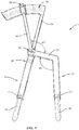
FIG. 1 is a perspective view of an apparatus for measuring spacing between first and second bone screws engaged with first and second bone structures, according to one embodiment. -
FIG. 2 is an exploded perspective view of the apparatus ofFIG. 1 . -
FIG. 3 is a perspective view of the apparatus ofFIG. 1 engaged with first and second bone screw extenders. -
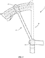
Fig. 4 is a perspective view of a proximal portion of an apparatus for measuring spacing between first and second bone screws engaged with first and second bone structures, according to one embodiment. -
Fig. 5 is a perspective view of bone screws and associated screw extenders engaged with first and second bone structures as part of a percutaneous fixation procedure, and a percutaneous rod inserter device suitable for engaging a spinal rod with the bone screws. - For the purposes of promoting an understanding of the principles of the invention, reference will now be made to the embodiments illustrated in the drawings and specific language will be used to describe the same. It will nevertheless be understood that no limitation of the scope of the invention is thereby intended. Any such alterations and further modifications in the illustrated devices, and such further applications of the principles of the invention as illustrated herein are contemplated as would normally occur to one skilled in the art to which the invention relates.
- Referring generally to
Figure 5 , apparatus and an exemplary method is provided for measuring spacing between first and second bone screws P1, P2 engaged with first and second bone structures V1, V2. As shown inFigure 3 , an apparatus, such as acaliper 1, may be inserted intobone screw extenders Figure 5 , a surgeon may wish to accurately measure and/or estimate the spacing S between adjacent first and second bone screws P1, P2 in a spinal surgery such that a spinal rod R having an appropriate length may be chosen from a plurality of spinal rod R sizes to connect adjacent first and second bone screws P1, P2. For example, as shown inFigure 5 , a surgeon may seek to estimate the length of spinal rod R that should be implanted using a minimally-invasive rod insertion technique such as that offered by the CD Horizon® Longitude™ Multi-level Percutaneous Fixation System developed by Medtronic Spinal and Biologics, of Memphis Tennessee. The various embodiments described herein provideexemplary caliper 1 apparatus for accurately measuring the spacing S between adjacent first and second bone screws P1, P2 engaged withbone screw extenders exemplary caliper 1 apparatus and related methods described herein may include acaliper 1 that is sized and/or calibrated to measure spacing S between adjacent bone screws P1, P2 without the use of interveningbone screw extenders 40, 50 (such as in "open" or non-percutaneous surgical procedures). - Referring to
Figure 1 , acaliper 1, may comprise afirst arm 10 having adistal end 12 adapted to engage the first bone screw P1 (according to the present invention, via thebone screw extender 40, as shown inFigure 4 ). Thefirst arm 10 also comprises aproximal end 16 comprising a graduatedscale 15 extending therefrom. Thecaliper 1 further comprises asingle pivot pin 30 operably engaged with thefirst arm 10 between thedistal end 12 and theproximal end 16 thereof. Thecaliper 1 further comprises asecond arm 20 operably engaged with thefirst arm 10 via thesingle pivot pin 30. Thesecond arm 20 also has adistal end 22 adapted to engage the second bone screw P2 (according to the present invention, via thebone screw extender 50, as shown inFigure 4 ), and aproximal end 26 comprising anindicator segment 25 slidably engaged with the graduatedscale 15 such that a position of theindicator segment 25 relative to the graduatedscale 15 is indicative of a spacing S between the first and second bone screws P1, P2 (seeFigure 3 , for example, where the spacing S is shown betweendistal ends bone screw extenders - Referring again to
Figure 1 , the distal ends of the first andsecond arms cylindrical elements bone screw extender 40 and a second bone screw extender 50 (seeFigure 3 , for example) extending respectively from the first and second bone screws P1, P2 (seeFigure 5 , for example). The distal ends of the first andsecond arms stop elements cylindrical elements bone screw extenders cylindrical elements cylindrical elements screw extenders - Referring again to the
first arm 10, shown generally inFigures 1-3 , the distal andproximal ends first arm 10 may be assembled and/or formed to be substantially parallel. In some examples not part of the present invention, thefirst arm 10 may be substantially straight along its length. In the embodiments, thefirst arm 10 comprises an offsetmember 14 configured to place thedistal end 12 of thecaliper 1 in a common plane of movement with the correspondingdistal end 22 of thesecond arm 20 of thecaliper 1 such that each of the first andsecond arms bone screw extenders scale 15 of thecaliper 1. - As shown in
Figure 1 , the graduatedscale 15 may comprise an arcuate member extending from theproximal end 16 of thefirst arm 10. Furthermore, thesecond arm 20 comprises aproximal end 26 comprising anindicator segment 25 slidably engaged with the graduatedscale 15 such that a position of theindicator segment 25 relative to the graduatedscale 15 is indicative of a spacing S between the first and second bone screws P1, P2. In some such embodiments, as shown generally inFigure 4 , thecaliper 1 comprises a plurality ofmarkings 17 disposed on the graduatedscale 15. In such embodiments, the plurality ofmarkings 17 are configured to account for a length of the first and secondbone screw extenders indicator segment 25 relative to the graduatedscale 15 is indicative of a screw spacing S between the first bone screw P1 and the second bone screw P2 operably engaged withdistal ends bone screw extenders Figure 4 , theindicator segment 25 may define a window or other aperture through which themarkings 17 of the graduatedscale 15 may be visible to a surgeon, wherein themarkings 17 are indicative of a length or other spacing S measurement between adjacent bone screws P1, P2 as indicated by the relative positions of the distal ends 12, 22 of thearms caliper 1. Themarkings 17 may be printed, etched, cut or otherwise made visible on the graduated scale and may be calibrated to adjust for variations in the geometry of thearms pivot pin 30. The surgeon may then select a spinal rod R (seeFigure 5 , for example) having an appropriate length to connect adjacent bone screws P1, P2 implanted in bone structures V1, V2. The surgeon may implant the spinal rod R using a number of different available surgical techniques, including but not limited to those associated with the CD Horizon™ Longitude® system available from Medtronic Spinal and Biologics of Memphis, Tennessee as shown generally inFigure 5 . - As shown in
Figures 1 and2 , thecalipers 1 disclosed herein may be formed and/or constructed with a number of bends, angles and other geometric features that allow for the spacing S to be accurately reflected in the position of theindicator segment 25 relative to the graduatedscale 15 when the distal ends 12, 22 of thecaliper 1 are engaged with a first bone screw P1 and a second bone screw P2 (in some instances, with first and secondbone screw extenders Figure 1 , thesecond arm 20 of thecaliper 1 may comprise atransverse member 24 disposed between thedistal end 22 and theproximal end 26 of thesecond arm 20. It will be appreciated that the length and/or position of thetransverse member 24 may be selected to account for differences in the length of thearms bone screw extenders caliper 1, such that the reading indicated by the position of theindicator segment 25 relative to the graduatedscale 15 may accurately reflect the spacing S between adjacent bone screws P1, P2. - Other geometric features of the
caliper 1 may also be selected to provide accurate measurements of the spacing S between adjacent bone screws P1, P2. For example, in some embodiments, the distal and proximal ends 22, 26 of thesecond arm 20 may be substantially parallel. Furthermore, thetransverse member 24 may extend at a first obtuse angle A1 relative to thedistal end 22 of thesecond arm 20. Thetransverse member 24 may also extend at a second obtuse angle A2 relative to theproximal end 26 of thesecond arm 20. In some embodiments, the first and second obtuse angles A1, A2 may be equal. Such geometric features may be utilized to accurately shape and size thecaliper 1 components such that the graduated scale 15 (and the position of theindicator segment 25 relative to the graduated scale 15) accurately reflects a spacing S measured between the distal ends 12, 22 of thecaliper 1. The described features of thecaliper 1 may be adjusted and/or modified as will be appreciated by one of skill in the art to allow for the accommodation of varyingbone screw extenders Figure 3 ). - Referring again to
Figure 3 , the embodiments comprise a complete system for percutaneous implantation of spinal instrumentation comprising acaliper 1, a caliper-compatible firstbone screw extender 40 adapted to implant a first bone screw P1 at a first bone structure V1 and a caliper-compatible secondbone screw extender 50 adapted to implant a second bone screw P2 at a second bone structure V2 (see also,Figure 5 showing theextenders caliper 1 as described herein having suitable geometric configuration for measuring spacing S between adjacent bone screws P1, P2 engaged withdistal ends extenders Figure 3 ). As depicted generally inFigure 3 , thecaliper 1 comprises afirst arm 10 having adistal end 12 adapted to engage the firstbone screw extender 40, and aproximal end 16 comprising a graduatedscale 15 extending therefrom. Thecaliper 1 comprises asingle pivot pin 30 operably engaged with thefirst arm 10 between thedistal end 12 and theproximal end 16 thereof, and asecond arm 20 operably engaged with thefirst arm 10 via thesingle pivot pin 30. Thesecond arm 20 comprises adistal end 22 adapted to engage the secondbone screw extender 50 and aproximal end 26 comprising anindicator segment 25 slidably engaged with the graduatedscale 15 such that a position of theindicator segment 25 relative to the graduated scale 15 (and/or relative tomarkings 17 thereon, as shown inFigure 4 ) is indicative of a spacing S between the first and second bone screws P1, P2. As shown inFigure 5 , once the spacing S is determined using thecaliper 1, a surgeon may also use arod introducer device 70 configured for operably engaging a spinal rod R between the first and second bone screws P1, P2, wherein a length of the spinal rod R is determined at least in part by the spacing S indicated by the graduatedscale 15 of thecaliper 1. - Various exemplary methods are also provided for measuring spacing S between first and second bone screws P1, P2 engaged with first and second bone structures V1, V2. Such an exemplary method comprises engaging a first
bone screw extender 40 with the first bone screw P1, engaging a secondbone screw extender 50 with the second bone screw. Engaging the first bone screw P1 and the firstbone screw extender 40 with the first bone structure, and engaging the second bone screw P2 and the secondbone screw extender 50 with the second bone structure V2 (seeFigure 5 ). Such exemplary methods further comprise pivoting afirst arm 10 and asecond arm 20 of a caliper 1 (seeFigure 1 ) relative to one another about asingle pivot pin 30 operably engaged with the first andsecond arms second arms caliper 1 are insertable into the first and secondbone screw extenders - The exemplary method further comprises inserting the
first arm 10 of thecaliper 1 into the firstbone screw extender 40, wherein thefirst arm 10 has adistal end 12 configured to engage the firstbone screw extender 40. For example, thedistal end 12 comprises a cylindrical element configured to fit within a complementary cylindrical channel defined in thebone screw extenders first arm 10 also includes aproximal end 16 comprising a graduatedscale 15 extending therefrom. The exemplary method further comprises inserting thesecond arm 20 of thecaliper 1 in the secondbone screw extender 50. As described herein, thesecond arm 20 may be provided with a distal end 12 (which may comprise a cylindrical element as shown inFigures 1 and2 ) configured to engage the secondbone screw extender 50, and aproximal end 26 comprising anindicator segment 25 slidably engaged with the graduatedscale 15 of thefirst arm 10 such that a position of theindicator segment 25 relative to the graduatedscale 15 is indicative of a spacing S between the first and second bone screws P1, P2 (seeFigure 5 , for reference). - Various exemplary methods may further comprise removing the first and
second arms caliper 1 from the first and secondbone screw extenders Figure 5 , for example). The measurement of the spacing S is then employed to select a connecting element (such as a spinal rod R) of the desired length, or used to modify the length of an existing spinal rod R or other connecting element, to fit the space S between bone screws P1, P2. - In some examples, the
caliper 1 may be used multiple times in a single procedure to determine an overall length of spinal rod R (or other connector) that may be used to connect multi-level spinal instrumentation. For example, thecaliper 1 may be used to determine an overall length of spinal rod R to connect a series of four bone screws (attached to four bone screw extenders as shown generally inFigure 5 ) by: first measuring the spacing S between the first and secondbone screw extenders bone screw extenders bone screw extenders - As shown generally in
Figure 5 , the exemplary method may also comprise connecting the first and second bone screws P1, P2 using the spinal rod R by operably engaging the spinal rod R with a head portion of the first and second bone screws P1, P2. This step may be accomplished, for example, using a rod-introduction device 70 as shown generally inFigure 5 . In spinal surgical procedures, the selected connecting element (such as a spinal rod R) can be delivered to one or more vertebrae V1, V2 in an anterior approach, a posterior approach, a lateral approach, postero-lateral approach, a transforaminal approach, or an anterior-oblique approach, for example. Vertebrae V1, V2 can comprise all or a portion of the cervical, thoracic, lumbar and sacral vertebrae of the spinal column. In addition to stabilization of one or more spinal motion segments with spinal rod R, other spinal repair procedures can be performed as an additional procedure, including procedures to fuse vertebrae with one or more implants or bone graft, to replace one or more vertebral bodies, to repair annulus tissue, or to insert artificial disc components, for example. Applications in non-spinal procedures are also contemplated. - The spinal rod R is rigid in one example to prevent motion between the bone structures V1, V2 to which it is attached via the bone screws P1, P2. In another example spinal rod R is fabricated from one or more components that are flexible or exhibit at least some flexibility or non-rigidity to permit motion of the stabilized vertebral level or levels. Some examples include extruded components, machined components, molded components, formed components, and milled components.
- The various embodiments described herein may also be used to measure spacing S for a number of different types of connecting element that may include any one or more of sheets, tethers, cords, planar members, bands, wires, cables, rods, bars, woven structures, or any other component capable of forming or being formed into the implant body. In a further form, such connecting element is resilient and/or elastic in whole or in part so it can assume various shapes during and after insertion and attachment while exhibiting a tendency to return to its natural form. In yet another form, connecting element is substantially inelastic so that the shape achieved upon insertion or deformation is maintained.
- Connecting element and/or spinal rod R can be made from any biocompatible material, material of synthetic or natural origin, and material of a resorbable or non-resorbable nature. Suitable examples of implant material include autograft, allograft or xenograft; tissue materials including soft tissues, connective tissues, demineralized bone matrix and combinations thereof; resorbable materials including polylactide, polyglycolide, tyrosinederived polycarbonate, polyanhydride, polyorthoester, polyphosphazene, calcium phosphate, hydroxyapatite, bioactive glass, collagen, albumin, fibrinogen and combinations thereof; and non-resorbable materials including polyethylene, polyester, polyvinyl alcohol, polyacrylonitrile, polyamide, polytetrafluorethylene, polyparaphenylene terephthalamide, cellulose, carbon-reinforced polymer composites, PEEK, shape memory alloys, titanium, titanium alloys, cobalt chrome alloys, stainless steel, and combinations thereof.
- One specific example of a suitable bone screw P1, P2 usable in the various embodiments described herein is a multi-axial screw such as described in
U.S. Pat. Nos. 5,797,911 and5,879,350 . Other examples for bone screws P1, P2 include uni-axial screws, bolts, specialty pedicle screws, and pins, for example. It is further contemplated that one or more of the bone screws P1, P2 can include a multi-axial head and one or more of the other anchors include a uni-axial head. The bone screws P1, P2 can be cannulated to facilitate placement over a guidewire and into the vertebra in minimally invasive procedures, or can be non-cannulated. Cannulated bone screws P1, P2 can further include one or more fenestrations or openings for placement of bone cement or other material therethrough. - Pre-operative planning and image guided navigation of anchor placement and installation of the connecting element and/or spinal rod R are also contemplated. The surgical techniques can employ any type of known imaging system to determine and locate optimum placement and orientation of the anchors in the bony structure and, if necessary, to locate skin locations for percutaneous puncture entry of the anchors and connecting element.
- Bone screw P1, P2 insertion can be monitored using any known viewing instrument or apparatus, and performed under any known surgical technique. For example, bone screws P1, P2 can be placed through a cannula or sleeve inserted through the skin that forms a working channel to a location over the target bone structures V1, V2. Bone screw placement into the bone structure can be monitored endoscopically, microscopically, fluoroscopically, radiographically and/or with naked eye visualization through the cannula. Bone screw placement can also be performed through micro-incisions, or through open incisions in which the skin and tissue is retracted to expose the bony structure.
- In one specific technique for placing bone screws P1, P2, a guidewire of sufficient length is inserted percutaneously and anchored to the bony structure, such as a pedicle of the vertebra (V1, V2, for example). The guidewire is coupled to a trackable instrument that is tracked via an image guided surgical system that generates a display on a computer monitor. With the guidewire secured at the appropriate location on the bone structure, various instruments for preparing and inserting the bone screw into the bone structure can be guided by the guidewire. The preparation and insertion can be monitored via a tracking instrument coupled to the various preparation and insertion instruments, and anchor extensions (such as
bone screw extenders 40, 50) are mounted to the engaged bone screw P1, P2. The length of the connecting element (such as spinal rod R) between the engaged bone screws P1, P2 is then determined withcaliper 1 mounted to the proximal ends of thebone screw extenders - Bone screws P1, P2 can be engaged on both sides of a midline of the spine, and along one or more levels of the spine. The bone screws P1, P2 can be engaged to stabilize adjacent vertebra in conjunction with any minimally invasive or open surgical techniques for placement of one or more implants into a disc space. For example, one or more interbody fusion devices or intervertebral spacers may be inserted into the disc space via an anterior, anterior oblique, lateral, postero-lateral, or transforaminal approach, and a connecting element (including, but not limited to spinal rod R) can be positioned and engaged to the spinal column segment from a posterior approach (see
FIG. 5 , for example). Further, connecting element (such as spinal rod R) can be used to stabilize adjacent vertebrae, or any other bony structure, without placement of implants between structures comprising bony segment.
Claims (6)
- A system for percutaneous implementation of spinal instrumentation comprising:an apparatus for measuring spacing between first (P1) and second (P2) bone screws engaged with first (V1) and second (V2) bone structures, comprising:a first arm (10) having a distal end (12) adapted to engage a first bone screw extender (40), and a proximal end (16) comprising a graduated scale (15) extending therefrom;a single pivot pin (30) operably engaged with the first arm (10) between the distal end (12) and the proximal end (16) thereof; anda second arm (20) operably engaged with the first arm (10) via the single pivot pin (30), the second arm (20) having a distal end (22) adapted to engage a second bone screw extender (50), and a proximal end (26) comprising an indicator segment (25) slidably engaged with the graduated scale (15) such that a position of the indicator segment (15) relative to the graduated scale (15) is indicative of a spacing between the first and second bone screws (P1, P2), wherein the first arm (10) comprises an offset member (14) configured to place the distal end (12) of the first arm (10) in a common plane of movement with the distal end (22) of the second arm (20) and out of a plane of movement of the proximal end (16) of the first arm (10),wherein the distal ends (12, 22) of the first and second arms (10, 20) comprise cylindrical elements configured to be insertable into the first bone screw extender (40) and the second bone screw extender (50) extending respectively from the first (P1) and second (P2) bone screws, andwherein the distal ends (12, 22) of the first and second arms (10, 20) comprise stop elements (11, 21) formed thereon that ensure that the cylindrical elements extend only a selected distance into a complementary set of cylindrical bores defined in the first and second bone screw extenders (40, 50), the system further comprisingthe first bone screw extender (40) adapted to be engaged with the first bone screw (P1) at the first bone structure (V1),the second bone screw extender (50) adapted to be engaged with the second bone screw (P2) at the second bone structure (V2), anda plurality of markings (17) disposed on the graduated scale (15), the plurality of markings (17) being configured to account for a length of the first (40) and second bone screw extenders (50) such that a position of the indicator segment (25) relative to the graduated scale (15) is indicative of a screw spacing between the first bone screw (P1) and the second bone screw (P2) operably engaged with distal ends (41, 51) of the first and second bone screw extenders (40, 50).
- The system of claim 1, wherein distal (12) and proximal ends (16) of the first arm (10) are substantially parallel.
- The system of claim 1, wherein the graduated scale (15) comprises an arcuate member extending from the proximal end (16) of the first arm (10).
- The system of claim 1, wherein the second arm (20) comprises a transverse member (24) disposed between the distal and proximal ends (22, 26) thereof.
- The system of claim 4, wherein the distal and proximal ends (22, 26) of the second arm (20) are substantially parallel and wherein the transverse member (24) extends at a first obtuse angle (A1) relative to the distal end (22) of the second arm (20) and at a second obtuse angle (A2) relative to the proximal end (26) of the second arm (20).
- The system of claim 5, wherein the first and second obtuse angles (A1, A2) are equal.
Applications Claiming Priority (2)
| Application Number | Priority Date | Filing Date | Title |
|---|---|---|---|
| US13/088,941 US9345547B2 (en) | 2011-04-18 | 2011-04-18 | Apparatus and method for sizing a connecting element for positioning along a bone structure |
| PCT/US2012/033646 WO2012145253A1 (en) | 2011-04-18 | 2012-04-13 | Apparatus and method for sizing a connecting element for positioning along a bone structure |
Publications (3)
| Publication Number | Publication Date |
|---|---|
| EP2699177A1 EP2699177A1 (en) | 2014-02-26 |
| EP2699177A4 EP2699177A4 (en) | 2014-08-20 |
| EP2699177B1 true EP2699177B1 (en) | 2017-12-20 |
Family
ID=47006977
Family Applications (1)
| Application Number | Title | Priority Date | Filing Date |
|---|---|---|---|
| EP12774055.3A Active EP2699177B1 (en) | 2011-04-18 | 2012-04-13 | Apparatus for sizing a connecting element for positioning along a bone structure |
Country Status (4)
| Country | Link |
|---|---|
| US (2) | US9345547B2 (en) |
| EP (1) | EP2699177B1 (en) |
| AU (1) | AU2012245700B2 (en) |
| WO (1) | WO2012145253A1 (en) |
Families Citing this family (17)
| Publication number | Priority date | Publication date | Assignee | Title |
|---|---|---|---|---|
| US20130317557A1 (en) * | 2012-05-26 | 2013-11-28 | Custom Spine, Inc. | Mis rod insertion device and method |
| US9005205B2 (en) | 2013-03-04 | 2015-04-14 | Degen Medical, Inc. | Rod insertion tools, rods and methods |
| US9655659B2 (en) | 2013-04-20 | 2017-05-23 | Degen Medical, Inc. | Anchor tower |
| US9453526B2 (en) | 2013-04-30 | 2016-09-27 | Degen Medical, Inc. | Bottom-loading anchor assembly |
| US9452026B2 (en) | 2013-05-15 | 2016-09-27 | Ebi, Llc | Apparatus and method for measuring a length between implanted bone anchors |
| GB201322577D0 (en) * | 2013-12-19 | 2014-02-05 | Univ Nottingham | Surgical device |
| DE102015120955A1 (en) * | 2015-12-02 | 2017-06-08 | Aesculap Ag | Medical instrument and medical instrument |
| US10013886B2 (en) | 2016-03-08 | 2018-07-03 | International Business Machines Corporation | Drone carrier |
| US9852642B2 (en) | 2016-03-08 | 2017-12-26 | International Business Machines Corporation | Drone air traffic control and flight plan management |
| US10417917B2 (en) | 2016-03-08 | 2019-09-17 | International Business Machines Corporation | Drone management data structure |
| US10062292B2 (en) | 2016-03-08 | 2018-08-28 | International Business Machines Corporation | Programming language for execution by drone |
| US9950791B2 (en) | 2016-03-08 | 2018-04-24 | International Business Machines Corporation | Drone receiver |
| CN108225142B (en) * | 2016-12-12 | 2023-12-12 | 创生医疗器械(中国)有限公司 | Measuring ruler |
| EP3517062B1 (en) * | 2018-01-26 | 2021-03-17 | Aesculap AG | Spinal repositioning instrument and spinal repositioning system |
| US11617602B2 (en) * | 2020-04-16 | 2023-04-04 | Medtronic, Inc. | Systems, methods of use and surgical instruments employing a secure slide lock to fasten a head |
| US11439442B2 (en) * | 2020-04-16 | 2022-09-13 | Warsaw Orthopedic, Inc. | Modular screw system with head locker and derotator |
| CN113456202A (en) * | 2021-03-23 | 2021-10-01 | 上海长征医院 | Accurate measurement matching device before spinal titanium rod is implanted |
Citations (1)
| Publication number | Priority date | Publication date | Assignee | Title |
|---|---|---|---|---|
| US20080200919A1 (en) * | 2007-02-19 | 2008-08-21 | Lanx Medical, Inc. | Tool to dissect or compress and measure a vertebral body segment |
Family Cites Families (21)
| Publication number | Priority date | Publication date | Assignee | Title |
|---|---|---|---|---|
| US2045298A (en) * | 1932-10-06 | 1936-06-23 | Eagle Pencil Co | Drafting compass |
| US4226025A (en) * | 1979-03-05 | 1980-10-07 | Wheeler Michael R | Surgical caliper |
| US4335715A (en) * | 1980-06-20 | 1982-06-22 | Kirkley William H | Osteotomy guide |
| US5797911A (en) | 1996-09-24 | 1998-08-25 | Sdgi Holdings, Inc. | Multi-axial bone screw assembly |
| US5879350A (en) | 1996-09-24 | 1999-03-09 | Sdgi Holdings, Inc. | Multi-axial bone screw assembly |
| WO2003024344A1 (en) * | 2001-09-14 | 2003-03-27 | The Regents Of The University Of California | System and method for fusing spinal vertebrae |
| EP1442714A1 (en) * | 2003-02-03 | 2004-08-04 | Centerpulse Orthopedics Ltd. | Aiming aid for vertebrae |
| EP1470792B1 (en) * | 2003-04-24 | 2005-09-14 | Zimmer GmbH | Distance measurement instrument for pedical screws |
| US20050203532A1 (en) * | 2004-03-12 | 2005-09-15 | Sdgi Holdings, Inc. | Technique and instrumentation for intervertebral prosthesis implantation using independent landmarks |
| US7465306B2 (en) * | 2004-08-13 | 2008-12-16 | Warsaw Orthopedic, Inc. | System and method for positioning a connecting member adjacent the spinal column in minimally invasive procedures |
| US20070173745A1 (en) * | 2004-11-16 | 2007-07-26 | Jennifer Diederich | Rod length measuring instrument |
| US7811288B2 (en) * | 2004-12-02 | 2010-10-12 | Zimmer Spine, Inc. | Instruments and methods for adjusting separation distance of vertebral bodies with a minimally invasive spinal stabilization procedure |
| US7618424B2 (en) * | 2005-04-29 | 2009-11-17 | Warsaw Orthopedic, Inc. | Orthopedic instrument |
| US20080147078A1 (en) * | 2006-12-14 | 2008-06-19 | Francis Thomas J | Method and Device for Determining Appropriate Spinal Rod Length |
| US8734452B2 (en) * | 2006-12-15 | 2014-05-27 | Spinefrontier, Inc | Guidance system,tools and devices for spinal fixation |
| US7981115B2 (en) * | 2007-04-11 | 2011-07-19 | Warsaw Orthopedic, Inc. | Instruments and methods for sizing a connecting element for positioning along a bony segment |
| US8162951B2 (en) * | 2008-01-31 | 2012-04-24 | Innomed, Inc. | Femoral tibial spreader with tensor measurement |
| EP2742885B1 (en) * | 2008-10-23 | 2018-11-21 | Alphatec Spine, Inc. | Systems for spinal fixation |
| US8496661B2 (en) | 2008-11-03 | 2013-07-30 | Omni Surgical LLC | System and method for micro-invasive transfacet lumbar interbody fusion |
| USD638322S1 (en) * | 2009-11-24 | 2011-05-24 | Nobuhisa Teramoto | Jaw portion of calipers |
| US8834485B2 (en) * | 2010-08-06 | 2014-09-16 | Warsaw Orthopedic, Inc. | Measuring instrument for sizing an elongate stabilization element |
-
2011
- 2011-04-18 US US13/088,941 patent/US9345547B2/en active Active
-
2012
- 2012-04-13 EP EP12774055.3A patent/EP2699177B1/en active Active
- 2012-04-13 WO PCT/US2012/033646 patent/WO2012145253A1/en not_active Ceased
- 2012-04-13 AU AU2012245700A patent/AU2012245700B2/en not_active Ceased
-
2016
- 2016-04-21 US US15/135,300 patent/US10575918B2/en active Active
Patent Citations (1)
| Publication number | Priority date | Publication date | Assignee | Title |
|---|---|---|---|---|
| US20080200919A1 (en) * | 2007-02-19 | 2008-08-21 | Lanx Medical, Inc. | Tool to dissect or compress and measure a vertebral body segment |
Also Published As
| Publication number | Publication date |
|---|---|
| AU2012245700B2 (en) | 2016-05-19 |
| EP2699177A4 (en) | 2014-08-20 |
| US9345547B2 (en) | 2016-05-24 |
| EP2699177A1 (en) | 2014-02-26 |
| US10575918B2 (en) | 2020-03-03 |
| US20120265212A1 (en) | 2012-10-18 |
| WO2012145253A1 (en) | 2012-10-26 |
| US20160235499A1 (en) | 2016-08-18 |
| AU2012245700A1 (en) | 2013-10-17 |
Similar Documents
| Publication | Publication Date | Title |
|---|---|---|
| US10575918B2 (en) | Apparatus and method for sizing a connecting element for positioning along a bone structure | |
| US7981115B2 (en) | Instruments and methods for sizing a connecting element for positioning along a bony segment | |
| EP3406226B1 (en) | Spinal implant system | |
| US20220280203A1 (en) | Anterior cervical instrumentation systems, methods and devices | |
| US7822465B2 (en) | Device and method for image-based device performance measurement | |
| US20110166610A1 (en) | Systems and methods for stabilization of bone structures, including thorocolumbar stabilization systems and methods | |
| US20080255615A1 (en) | Treatments for Correcting Spinal Deformities | |
| US20260076685A1 (en) | Surgical implant system and methods of use | |
| US8147529B2 (en) | Anterior cervical instrumentation systems, methods and devices | |
| US20080249531A1 (en) | Instruments and methods for minimally invasive insertion of dynamic implants | |
| CN113710179A (en) | Surgical system and method | |
| US10172719B2 (en) | Surgical system and method of use | |
| EP4027953B1 (en) | Spinal implant system | |
| HK40078351B (en) | Interlaminar lumbar interbody fusion system and associated robotic systems |
Legal Events
| Date | Code | Title | Description |
|---|---|---|---|
| PUAI | Public reference made under article 153(3) epc to a published international application that has entered the european phase |
Free format text: ORIGINAL CODE: 0009012 |
|
| 17P | Request for examination filed |
Effective date: 20130924 |
|
| AK | Designated contracting states |
Kind code of ref document: A1 Designated state(s): AL AT BE BG CH CY CZ DE DK EE ES FI FR GB GR HR HU IE IS IT LI LT LU LV MC MK MT NL NO PL PT RO RS SE SI SK SM TR |
|
| DAX | Request for extension of the european patent (deleted) | ||
| A4 | Supplementary search report drawn up and despatched |
Effective date: 20140721 |
|
| RIC1 | Information provided on ipc code assigned before grant |
Ipc: A61B 17/58 20060101AFI20140715BHEP Ipc: A61B 5/103 20060101ALN20140715BHEP Ipc: A61B 19/00 20060101ALN20140715BHEP Ipc: A61B 17/70 20060101ALI20140715BHEP |
|
| 17Q | First examination report despatched |
Effective date: 20150528 |
|
| REG | Reference to a national code |
Ref country code: DE Ref legal event code: R079 Ref document number: 602012041140 Country of ref document: DE Free format text: PREVIOUS MAIN CLASS: A61B0017560000 Ipc: A61B0017700000 |
|
| RIC1 | Information provided on ipc code assigned before grant |
Ipc: A61B 17/70 20060101AFI20170519BHEP Ipc: A61B 90/00 20160101ALI20170519BHEP |
|
| GRAP | Despatch of communication of intention to grant a patent |
Free format text: ORIGINAL CODE: EPIDOSNIGR1 |
|
| INTG | Intention to grant announced |
Effective date: 20170711 |
|
| GRAS | Grant fee paid |
Free format text: ORIGINAL CODE: EPIDOSNIGR3 |
|
| GRAA | (expected) grant |
Free format text: ORIGINAL CODE: 0009210 |
|
| AK | Designated contracting states |
Kind code of ref document: B1 Designated state(s): AL AT BE BG CH CY CZ DE DK EE ES FI FR GB GR HR HU IE IS IT LI LT LU LV MC MK MT NL NO PL PT RO RS SE SI SK SM TR |
|
| REG | Reference to a national code |
Ref country code: GB Ref legal event code: FG4D |
|
| REG | Reference to a national code |
Ref country code: CH Ref legal event code: EP |
|
| REG | Reference to a national code |
Ref country code: IE Ref legal event code: FG4D |
|
| REG | Reference to a national code |
Ref country code: AT Ref legal event code: REF Ref document number: 955642 Country of ref document: AT Kind code of ref document: T Effective date: 20180115 |
|
| REG | Reference to a national code |
Ref country code: DE Ref legal event code: R096 Ref document number: 602012041140 Country of ref document: DE |
|
| REG | Reference to a national code |
Ref country code: FR Ref legal event code: PLFP Year of fee payment: 7 |
|
| REG | Reference to a national code |
Ref country code: NL Ref legal event code: MP Effective date: 20171220 |
|
| PG25 | Lapsed in a contracting state [announced via postgrant information from national office to epo] |
Ref country code: LT Free format text: LAPSE BECAUSE OF FAILURE TO SUBMIT A TRANSLATION OF THE DESCRIPTION OR TO PAY THE FEE WITHIN THE PRESCRIBED TIME-LIMIT Effective date: 20171220 Ref country code: SE Free format text: LAPSE BECAUSE OF FAILURE TO SUBMIT A TRANSLATION OF THE DESCRIPTION OR TO PAY THE FEE WITHIN THE PRESCRIBED TIME-LIMIT Effective date: 20171220 Ref country code: FI Free format text: LAPSE BECAUSE OF FAILURE TO SUBMIT A TRANSLATION OF THE DESCRIPTION OR TO PAY THE FEE WITHIN THE PRESCRIBED TIME-LIMIT Effective date: 20171220 Ref country code: NO Free format text: LAPSE BECAUSE OF FAILURE TO SUBMIT A TRANSLATION OF THE DESCRIPTION OR TO PAY THE FEE WITHIN THE PRESCRIBED TIME-LIMIT Effective date: 20180320 |
|
| REG | Reference to a national code |
Ref country code: LT Ref legal event code: MG4D |
|
| REG | Reference to a national code |
Ref country code: AT Ref legal event code: MK05 Ref document number: 955642 Country of ref document: AT Kind code of ref document: T Effective date: 20171220 |
|
| PG25 | Lapsed in a contracting state [announced via postgrant information from national office to epo] |
Ref country code: GR Free format text: LAPSE BECAUSE OF FAILURE TO SUBMIT A TRANSLATION OF THE DESCRIPTION OR TO PAY THE FEE WITHIN THE PRESCRIBED TIME-LIMIT Effective date: 20180321 Ref country code: HR Free format text: LAPSE BECAUSE OF FAILURE TO SUBMIT A TRANSLATION OF THE DESCRIPTION OR TO PAY THE FEE WITHIN THE PRESCRIBED TIME-LIMIT Effective date: 20171220 Ref country code: LV Free format text: LAPSE BECAUSE OF FAILURE TO SUBMIT A TRANSLATION OF THE DESCRIPTION OR TO PAY THE FEE WITHIN THE PRESCRIBED TIME-LIMIT Effective date: 20171220 Ref country code: RS Free format text: LAPSE BECAUSE OF FAILURE TO SUBMIT A TRANSLATION OF THE DESCRIPTION OR TO PAY THE FEE WITHIN THE PRESCRIBED TIME-LIMIT Effective date: 20171220 Ref country code: BG Free format text: LAPSE BECAUSE OF FAILURE TO SUBMIT A TRANSLATION OF THE DESCRIPTION OR TO PAY THE FEE WITHIN THE PRESCRIBED TIME-LIMIT Effective date: 20180320 |
|
| PG25 | Lapsed in a contracting state [announced via postgrant information from national office to epo] |
Ref country code: NL Free format text: LAPSE BECAUSE OF FAILURE TO SUBMIT A TRANSLATION OF THE DESCRIPTION OR TO PAY THE FEE WITHIN THE PRESCRIBED TIME-LIMIT Effective date: 20171220 |
|
| PG25 | Lapsed in a contracting state [announced via postgrant information from national office to epo] |
Ref country code: EE Free format text: LAPSE BECAUSE OF FAILURE TO SUBMIT A TRANSLATION OF THE DESCRIPTION OR TO PAY THE FEE WITHIN THE PRESCRIBED TIME-LIMIT Effective date: 20171220 Ref country code: CY Free format text: LAPSE BECAUSE OF FAILURE TO SUBMIT A TRANSLATION OF THE DESCRIPTION OR TO PAY THE FEE WITHIN THE PRESCRIBED TIME-LIMIT Effective date: 20171220 Ref country code: CZ Free format text: LAPSE BECAUSE OF FAILURE TO SUBMIT A TRANSLATION OF THE DESCRIPTION OR TO PAY THE FEE WITHIN THE PRESCRIBED TIME-LIMIT Effective date: 20171220 Ref country code: ES Free format text: LAPSE BECAUSE OF FAILURE TO SUBMIT A TRANSLATION OF THE DESCRIPTION OR TO PAY THE FEE WITHIN THE PRESCRIBED TIME-LIMIT Effective date: 20171220 Ref country code: SK Free format text: LAPSE BECAUSE OF FAILURE TO SUBMIT A TRANSLATION OF THE DESCRIPTION OR TO PAY THE FEE WITHIN THE PRESCRIBED TIME-LIMIT Effective date: 20171220 |
|
| PG25 | Lapsed in a contracting state [announced via postgrant information from national office to epo] |
Ref country code: PL Free format text: LAPSE BECAUSE OF FAILURE TO SUBMIT A TRANSLATION OF THE DESCRIPTION OR TO PAY THE FEE WITHIN THE PRESCRIBED TIME-LIMIT Effective date: 20171220 Ref country code: AT Free format text: LAPSE BECAUSE OF FAILURE TO SUBMIT A TRANSLATION OF THE DESCRIPTION OR TO PAY THE FEE WITHIN THE PRESCRIBED TIME-LIMIT Effective date: 20171220 Ref country code: SM Free format text: LAPSE BECAUSE OF FAILURE TO SUBMIT A TRANSLATION OF THE DESCRIPTION OR TO PAY THE FEE WITHIN THE PRESCRIBED TIME-LIMIT Effective date: 20171220 Ref country code: IS Free format text: LAPSE BECAUSE OF FAILURE TO SUBMIT A TRANSLATION OF THE DESCRIPTION OR TO PAY THE FEE WITHIN THE PRESCRIBED TIME-LIMIT Effective date: 20180420 Ref country code: RO Free format text: LAPSE BECAUSE OF FAILURE TO SUBMIT A TRANSLATION OF THE DESCRIPTION OR TO PAY THE FEE WITHIN THE PRESCRIBED TIME-LIMIT Effective date: 20171220 Ref country code: IT Free format text: LAPSE BECAUSE OF FAILURE TO SUBMIT A TRANSLATION OF THE DESCRIPTION OR TO PAY THE FEE WITHIN THE PRESCRIBED TIME-LIMIT Effective date: 20171220 |
|
| REG | Reference to a national code |
Ref country code: DE Ref legal event code: R097 Ref document number: 602012041140 Country of ref document: DE |
|
| PLBE | No opposition filed within time limit |
Free format text: ORIGINAL CODE: 0009261 |
|
| STAA | Information on the status of an ep patent application or granted ep patent |
Free format text: STATUS: NO OPPOSITION FILED WITHIN TIME LIMIT |
|
| 26N | No opposition filed |
Effective date: 20180921 |
|
| PG25 | Lapsed in a contracting state [announced via postgrant information from national office to epo] |
Ref country code: DK Free format text: LAPSE BECAUSE OF FAILURE TO SUBMIT A TRANSLATION OF THE DESCRIPTION OR TO PAY THE FEE WITHIN THE PRESCRIBED TIME-LIMIT Effective date: 20171220 Ref country code: MC Free format text: LAPSE BECAUSE OF FAILURE TO SUBMIT A TRANSLATION OF THE DESCRIPTION OR TO PAY THE FEE WITHIN THE PRESCRIBED TIME-LIMIT Effective date: 20171220 |
|
| REG | Reference to a national code |
Ref country code: CH Ref legal event code: PL |
|
| REG | Reference to a national code |
Ref country code: BE Ref legal event code: MM Effective date: 20180430 |
|
| GBPC | Gb: european patent ceased through non-payment of renewal fee |
Effective date: 20180413 |
|
| REG | Reference to a national code |
Ref country code: IE Ref legal event code: MM4A |
|
| PG25 | Lapsed in a contracting state [announced via postgrant information from national office to epo] |
Ref country code: LU Free format text: LAPSE BECAUSE OF NON-PAYMENT OF DUE FEES Effective date: 20180413 |
|
| PG25 | Lapsed in a contracting state [announced via postgrant information from national office to epo] |
Ref country code: SI Free format text: LAPSE BECAUSE OF FAILURE TO SUBMIT A TRANSLATION OF THE DESCRIPTION OR TO PAY THE FEE WITHIN THE PRESCRIBED TIME-LIMIT Effective date: 20171220 Ref country code: GB Free format text: LAPSE BECAUSE OF NON-PAYMENT OF DUE FEES Effective date: 20180413 Ref country code: CH Free format text: LAPSE BECAUSE OF NON-PAYMENT OF DUE FEES Effective date: 20180430 Ref country code: BE Free format text: LAPSE BECAUSE OF NON-PAYMENT OF DUE FEES Effective date: 20180430 Ref country code: LI Free format text: LAPSE BECAUSE OF NON-PAYMENT OF DUE FEES Effective date: 20180430 |
|
| PG25 | Lapsed in a contracting state [announced via postgrant information from national office to epo] |
Ref country code: IE Free format text: LAPSE BECAUSE OF NON-PAYMENT OF DUE FEES Effective date: 20180413 |
|
| PG25 | Lapsed in a contracting state [announced via postgrant information from national office to epo] |
Ref country code: MT Free format text: LAPSE BECAUSE OF NON-PAYMENT OF DUE FEES Effective date: 20180413 |
|
| PG25 | Lapsed in a contracting state [announced via postgrant information from national office to epo] |
Ref country code: TR Free format text: LAPSE BECAUSE OF FAILURE TO SUBMIT A TRANSLATION OF THE DESCRIPTION OR TO PAY THE FEE WITHIN THE PRESCRIBED TIME-LIMIT Effective date: 20171220 |
|
| PG25 | Lapsed in a contracting state [announced via postgrant information from national office to epo] |
Ref country code: HU Free format text: LAPSE BECAUSE OF FAILURE TO SUBMIT A TRANSLATION OF THE DESCRIPTION OR TO PAY THE FEE WITHIN THE PRESCRIBED TIME-LIMIT; INVALID AB INITIO Effective date: 20120413 Ref country code: PT Free format text: LAPSE BECAUSE OF FAILURE TO SUBMIT A TRANSLATION OF THE DESCRIPTION OR TO PAY THE FEE WITHIN THE PRESCRIBED TIME-LIMIT Effective date: 20171220 |
|
| PG25 | Lapsed in a contracting state [announced via postgrant information from national office to epo] |
Ref country code: MK Free format text: LAPSE BECAUSE OF NON-PAYMENT OF DUE FEES Effective date: 20171220 |
|
| PG25 | Lapsed in a contracting state [announced via postgrant information from national office to epo] |
Ref country code: AL Free format text: LAPSE BECAUSE OF FAILURE TO SUBMIT A TRANSLATION OF THE DESCRIPTION OR TO PAY THE FEE WITHIN THE PRESCRIBED TIME-LIMIT Effective date: 20171220 |
|
| PGFP | Annual fee paid to national office [announced via postgrant information from national office to epo] |
Ref country code: DE Payment date: 20220322 Year of fee payment: 11 |
|
| REG | Reference to a national code |
Ref country code: DE Ref legal event code: R119 Ref document number: 602012041140 Country of ref document: DE |
|
| PG25 | Lapsed in a contracting state [announced via postgrant information from national office to epo] |
Ref country code: DE Free format text: LAPSE BECAUSE OF NON-PAYMENT OF DUE FEES Effective date: 20231103 |
|
| PGFP | Annual fee paid to national office [announced via postgrant information from national office to epo] |
Ref country code: FR Payment date: 20260320 Year of fee payment: 15 |