EP2698569B1 - Regulation valve - Google Patents
Regulation valve Download PDFInfo
- Publication number
- EP2698569B1 EP2698569B1 EP12180371.2A EP12180371A EP2698569B1 EP 2698569 B1 EP2698569 B1 EP 2698569B1 EP 12180371 A EP12180371 A EP 12180371A EP 2698569 B1 EP2698569 B1 EP 2698569B1
- Authority
- EP
- European Patent Office
- Prior art keywords
- valve
- liquid medium
- regulation
- chamber
- mounting support
- Prior art date
- Legal status (The legal status is an assumption and is not a legal conclusion. Google has not performed a legal analysis and makes no representation as to the accuracy of the status listed.)
- Active
Links
Images



Classifications
-
- F—MECHANICAL ENGINEERING; LIGHTING; HEATING; WEAPONS; BLASTING
- F16—ENGINEERING ELEMENTS AND UNITS; GENERAL MEASURES FOR PRODUCING AND MAINTAINING EFFECTIVE FUNCTIONING OF MACHINES OR INSTALLATIONS; THERMAL INSULATION IN GENERAL
- F16K—VALVES; TAPS; COCKS; ACTUATING-FLOATS; DEVICES FOR VENTING OR AERATING
- F16K31/00—Actuating devices; Operating means; Releasing devices
- F16K31/002—Actuating devices; Operating means; Releasing devices actuated by temperature variation
Definitions
- the invention relates to a regulation valve for a liquid like water, especially to a drinking water regulation valve for a drinking water circulation system.
- a drinking water regulation valve used in such a drinking water circulation system needs to provide an accurate regulation of the flow rate of the drinking water through the drinking water regulation valve depending on the temperature of the drinking water, especially at relative low temperatures of the drinking water at which an accurate relative low flow rate of the drinking water through the regulation valve has to be provided. Similar requirements have to be fulfilled by regulation valves for circulation systems of other liquid mediums.
- a novel regulation valve which provides an accurate regulation of the flow rate of the liquid medium through the regulation valve depending on the temperature of the liquid medium, especially at relative low temperatures of the liquid medium at which an accurate relative low flow rate of the liquid medium through the regulation valve has to be provided.
- a regulation valve according to the present invention is defined in claim 1.
- the invention provides a regulation valve providing an accurate regulation of the flow rate of the liquid medium through the regulation valve depending on the temperature of the liquid medium, especially at relative low temperatures of the liquid medium at which an accurate relative low flow rate of the liquid medium through the regulation valve has to be provided.
- the valve body of the valve insert does not move during operation of the regulation valve so that there is no risk that the same becomes blocked by containments of the liquid medium.
- the entire valve insert can easily be removed from the valve housing for service or replacement purposes.
- thermo element acts together with the valve plunger and the first spring element in such a way that at relative low temperatures of the liquid medium the regulation valve is closed by the first spring force being larger than the thermo element force thereby providing a low high flow rate of the liquid medium, and that at relative high temperatures of the liquid medium the regulation valve is opened by the thermo element force being larger than the first spring force thereby providing a relative high flow rate of the liquid medium.
- the invention relates to a regulation valve for a liquid medium like water, especially to a drinking water regulation valve for a drinking water circulation system.
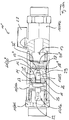
- Figures 1a , 1b each show a cross sectional view of a regulation valve 10 according to a first preferred embodiment of the invention, wherein Figure 1 a shows the regulation valve in a closed status, wherein Figure 1b shows the regulation valve in an opened status and wherein Figure 1c shows a detail of said regulation valve 10.
- the regulation valve 10 comprises a valve housing 11.
- the valve housing 11 provides a valve inlet chamber 12 for the liquid medium and a valve outlet chamber 13 for the liquid medium.
- the valve housing 11 shown in the embodiment of Figure 1 comprises a middle main section 11a and lateral connecting sections 11b, 11c being mounted together.
- the middle main section 11a of the valve housing 11 has a first end to which a first lateral connecting section 11b is mounted, preferably screwed, and a second end to which a second lateral connection section 11c carrying a shut-off element 27 is mounted, preferably screwed.
- the valve inlet chamber 12 is provided by the main section 11a and the first connecting section 11b.
- the valve outlet chamber 13 is provided by the main section 11a and the second connecting section 11b.
- the regulation valve 10 is connectable to a circulation system through the connecting sections 11b, 11c.
- the regulation valve 10 comprises a valve insert being positioned within said valve housing 11, namely with the main section 11a of the valve housing 11.
- Said valve insert comprise a valve body 18, a valve plunger 19 and a first spring element 20.
- the first spring element 20 is positioned between the valve body 18 and the valve plunger 19 and acts on the valve body 18 and the valve plunger 19.
- Said valve body 18 separates the second inlet chamber 12 from the outlet chamber 13 and provides a valve seat 21 for a corresponding sealing surface 30 of said valve plunger 19.
- Said first spring element 20 provides a first spring force which tends close the regulation valve by bringing the sealing surface 30 of said valve plunger 19 in contact with said valve seat 21.
- the regulation valve 10 further comprises a thermo element 22 being positioned directly in the flow of the liquid medium, namely in the embodiment of Figure 1 directly within the valve inlet chamber 12 of the regulation valve 10.
- Said thermo element 22 provides a thermo element force depending on the temperature of the liquid medium within the valve housing 11, namely in the embodiment of Figure 1 within the valve inlet chamber 12.
- thermo element 22 is carrying said valve plunger 19 and is acting on the valve plunger 19.
- Said thermo element force provided by said thermo element 22 is acting against the first spring force provided by said first spring element 20 and thereby tends to open the regulation valve 10 by bringing the sealing surface 30 of said valve plunger 19 out of contact with said valve seat 21.
- Said thermo element 22 acts together with the valve plunger 19 and the first spring element 20 in such a way that at relative low temperatures of the liquid medium the regulation valve 10 is or becomes closed, thereby providing a relative low flow rate of the liquid medium through the regulation valve 10. At relative high temperatures of the liquid medium the regulation valve 10 is or becomes opened, thereby providing a relative high flow rate of the liquid medium through the regulation valve 10. The relative low flow rate is also often called minimum flow rate.
- the thermo element 22 is positioned directly in the flow of the liquid medium. This allows a quick and accurate reaction on a changing temperature of the liquid medium and therefore an accurate regulation of the flow rate of the liquid medium through the regulation valve 10 depending on the temperature of the liquid medium.
- Said valve body 10 provides at least one relative large opening 23 which is opened when the regulation vale is opened at relative high temperatures of the liquid medium thereby providing the relative high flow rate.
- the or each relative large opening 23 is closed when the regulation vale is opened at relative low temperatures of the liquid medium thereby providing the relative low flow rate.
- the or each relative large opening 23 of the valve body 18 is completely closed when the sealing surface 30 of the valve plunger 19 is in contact with the valve seat 21 of the valve body 18.
- the relative low flow rate or minimum flow rate through the regulation valve is provided by at least one additional, relative small opening 24 within the valve body 18.
- the or each additional, relative small opening 24 within the valve body 18 is opened when the sealing surface 30 of the valve plunger 19 is in contact with the valve seat 21 of the valve body 18 thereby providing a highly accurate relative low flow rate at relative low temperatures of the liquid medium.
- the or each additional, relative small opening 24 can be manufactured very precisely and the flow through the same does not depend on any other tolerances of the regulation valve 10.
- the regulation valve 10 further comprises a mounting support 14 carrying said thermo element 22, wherein a subassembly comprising said mounting support 14, said thermo element 22 and said valve plunger 19 is mounted within an opening 15 of said valve housing 11, namely of the main section 11b of the valve housing 11.
- the mounting support 14 separates the valve inlet chamber 12 into two sub-chambers, namely into a first inlet sub-chamber 12a and a second inlet sub-chamber 12b.
- the second valve inlet sub-chamber 12b in positioned between the first valve inlet sub-chamber 12a and the valve outlet chamber 13.
- the mounting support 14 allows a precise pre-assembling of a subassembly comprising said mounting support 14, said thermo element 22 and said valve plunger 19 outside the valve housing 11.
- the subassembly comprising said mounting support 14, said thermo element 22 and said valve plunger 19 can be easily installed into the valve housing 11. Further on, the subassembly can easily be easily removed from the valve housing 11 after the lateral connection section 11b has been unscrewed from the middle main section 11a.
- Said mounting support 14 is provided by a disc-like or plate like element having a central opening 16 carrying a section of said thermo element 22, said disc-like or plate like element having an outer surface 17 that allows a flow of said liquid medium across said mounting support 14, namely from the first valve inlet sub-chamber 12a into the second valve inlet sub-chamber 12b.
- the central opening 16 of said mounting support 14 carries a section of said thermo element 22.
- Another section of said thermo element 22 carries said valve plunger 19.
- a jacket 29 preferably made from a rubber material surrounds another section of said thermo element 22 extending between said mounting support 14 and said valve plunger 19.
- the regulation valve 10 further comprises a second spring element 25 being positioned in the first valve inlet sub-chamber 12a.
- the second spring element 25 acts on the mounting support 14 in such a way that the second spring element 25 provides a second spring force which presses the mounting support 14 against a stroke 26 provided by the valve housing 11, namely in the opening 15 of the main section 11a of the main housing 11.
- a first end of the second spring element 25 contacts the mounting support 14 and a second end of the second spring element 25 contacts a section of the valve housing 11.
- the second end of the second spring element 25 contacts the first connecting section 11b of the valve housing 11.
- the second spring force provided by the second spring element 25 presses the mounting support 14 against the stroke 26 provided by the main section 11a of the main housing 11 independently from the temperature of the liquid medium.
- the valve body 18 of the valve insert is pressed against an additional stroke 28 provided by the by the main section 11a of the main housing 11 independently from the temperature of the liquid medium. Neither the mounting support 14 nor the valve body 18 move during operation of the regulation valve 10 so that there is no risk that the same become blocked by containments of the liquid medium.
- the second spring element 25 is positioned in the first valve inlet sub-chamber 12a and that the second spring element 25 acts on the mounting support 14 in such a way that the second spring element 25 provides a second spring force which tends to press the mounting support 14 against the stroke 26 provided by the valve housing 11, the operating pressure of the regulation valve 10 needs not to be taken in consideration for sizing the second spring element 25.
- the second spring element does not need to act on the valve body against the thermo element force and the operating pressure. This makes it possible to use an inexpensive second spring element 25 having a large tolerance with respect to the second spring force provided by the same.
- valve body 18, the first spring element 20, the second spring element 25 and the subassembly comprising the mounting support 14, the thermo element 22 and the valve plunger 19 of the can easily be positioned in and removed from the valve housing 11, namely from the main section 11a of the main housing 11 when the first connection section 11b from valve housing 11 is disassembled from the main section 11a.
- the valve body 18 of the valve insert is preferably made from a plastics material. This has the advantage that the same is resistant to corrosion which may be caused by cavitations in the liquid medium.
- Figures 2a , 2b each show a cross sectional view of a regulation valve 10' according to a second preferred embodiment of the invention, wherein Figure 2a shows the regulation valve in a closed status, wherein Figure 2b shows the regulation valve 10' in an opened status and wherein Figures 2c, 2d shows a detail of said regulation valve 10'.
- the regulation valve 10' according to Figures 2a to 2d differs from the regulation valve 10 according to Figures 1a to 1c only by the design of the valve plunger 19, 19'.
- identical reference signs are used for identical parts of the two regulation valves 10, 10'.
- the regulation valve 10' only the differences of the valve plunger 19' will be described below. For all other details reference is made to above description of the regulation valve 10.
- the regulation valve 10 according to Figures 1a to 1c comprises a valve plunger 19 having a symmetric design relative to a longitudinal axis 31 of the same running in parallel to the moving direction of the valve plunger 19.
- the regulation valve 10' according to Figures 2a to 2d comprises a valve plunger 19' having a symmetric design relative to a longitudinal axis 31' of the same running in parallel to the moving direction of the valve plunger 19'.
- the liquid medium flows non-uniformly around or across the valve plunger 19' through the opening 23 when the regulation valve 10' is opened.
- the design of the valve plunger 19' is preferred because the same provides a better flow characteristic at relative low flow rates when the regulation valve 10' becomes opened by bringing the sealing surface 30' out of contact with the valve seat 21.
- Figures 3a , 3b each show a cross sectional view of a comparative regulation valve 10" not covered by the invention, wherein Figure 3a shows the regulation valve 10" in a closed status, wherein Figure 3b shows the regulation valve 10" in an opened status.
- the regulation valve 10" according to Figures 3a and 3b differs from the regulation valve 10 according to Figures 1a to 1c by the design of the valve body 18", the valve plunger 19", the first spring element 20". Identical reference signs are used for identical parts of the two regulation valves 10, 10". For the regulation valve 10" only the differences of the valve body 18", the valve plunger 19" and the first spring element 20" will be described below. For all other details reference is made to above description of the regulation valve 10.
- the valve body 18" of the regulation valve 10" comprises only the relative large opening 23 but not the relative small opening 24.
- the minimum flow rate through the regulation valve 10" is zero when the regulation valve 10" is closed by pressing the sealing surface 30" of the valve plunger 19" against the valve seat 21 provided by the valve body 18".
- the valve body 18" also comprises a relative small opening 24 to provide a minimum flow rate greater than zero.
- valve body 18" of the regulation valve 10" is kept in position by locking ring 33".
- locking ring 33 In the embodiments of Figures 1 a to 1c and 2a to 2d such a locking ring is superfluous because of the position of the first spring elements 22 acting on the respective valve body 18.
- the first spring element 20" of the regulation valve 10" is positioned between the valve plunger 19" and a supporting element 32" within the valve outlet chamber 13.
- the first spring element 20" contacts with a first end the valve plunger 19". With a second end the first spring element 20" contacts the supporting element 32".
- the design of Figures 1a to 1c is preferred because the same provides an easier assembly of the regulation valve.
Landscapes
- Engineering & Computer Science (AREA)
- General Engineering & Computer Science (AREA)
- Mechanical Engineering (AREA)
- Temperature-Responsive Valves (AREA)
Description
- The invention relates to a regulation valve for a liquid like water, especially to a drinking water regulation valve for a drinking water circulation system.
- In drinking water circulation systems it is necessary to provide a defined temperature of the drinking water circulated by the drinking water circulation system. A drinking water regulation valve used in such a drinking water circulation system needs to provide an accurate regulation of the flow rate of the drinking water through the drinking water regulation valve depending on the temperature of the drinking water, especially at relative low temperatures of the drinking water at which an accurate relative low flow rate of the drinking water through the regulation valve has to be provided. Similar requirements have to be fulfilled by regulation valves for circulation systems of other liquid mediums.
- A regulation valve according to the prior art is disclosed by
US 2007/075152 A1 . - Against this background, a novel regulation valve is provided which provides an accurate regulation of the flow rate of the liquid medium through the regulation valve depending on the temperature of the liquid medium, especially at relative low temperatures of the liquid medium at which an accurate relative low flow rate of the liquid medium through the regulation valve has to be provided.
- A regulation valve according to the present invention is defined in claim 1.
- The invention provides a regulation valve providing an accurate regulation of the flow rate of the liquid medium through the regulation valve depending on the temperature of the liquid medium, especially at relative low temperatures of the liquid medium at which an accurate relative low flow rate of the liquid medium through the regulation valve has to be provided. The valve body of the valve insert does not move during operation of the regulation valve so that there is no risk that the same becomes blocked by containments of the liquid medium. The entire valve insert can easily be removed from the valve housing for service or replacement purposes. The thermo element acts together with the valve plunger and the first spring element in such a way that at relative low temperatures of the liquid medium the regulation valve is closed by the first spring force being larger than the thermo element force thereby providing a low high flow rate of the liquid medium, and that at relative high temperatures of the liquid medium the regulation valve is opened by the thermo element force being larger than the first spring force thereby providing a relative high flow rate of the liquid medium.
- Preferred developments of the invention are provided by the dependent claims and the description which follows. Exemplary embodiments are explained in more detail on the basis of the drawing, in which:
- Figures 1a to 1c
- show details of a regulation valve according to a first embodiment of the invention;
- Figures 2a to 2d
- show details of a regulation valve according to a second embodiment of the invention;
- Figures 3a to 3b
- show details of a comparative regulation valve.
- The invention relates to a regulation valve for a liquid medium like water, especially to a drinking water regulation valve for a drinking water circulation system.
-
Figures 1a ,1b each show a cross sectional view of aregulation valve 10 according to a first preferred embodiment of the invention, whereinFigure 1 a shows the regulation valve in a closed status, whereinFigure 1b shows the regulation valve in an opened status and whereinFigure 1c shows a detail of saidregulation valve 10. - The
regulation valve 10 comprises avalve housing 11. Thevalve housing 11 provides avalve inlet chamber 12 for the liquid medium and avalve outlet chamber 13 for the liquid medium. Thevalve housing 11 shown in the embodiment ofFigure 1 comprises a middlemain section 11a and lateral connecting sections 11b, 11c being mounted together. The middlemain section 11a of thevalve housing 11 has a first end to which a first lateral connecting section 11b is mounted, preferably screwed, and a second end to which a second lateral connection section 11c carrying a shut-offelement 27 is mounted, preferably screwed. - The
valve inlet chamber 12 is provided by themain section 11a and the first connecting section 11b. Thevalve outlet chamber 13 is provided by themain section 11a and the second connecting section 11b. Theregulation valve 10 is connectable to a circulation system through the connecting sections 11b, 11c. - The
regulation valve 10 comprises a valve insert being positioned within saidvalve housing 11, namely with themain section 11a of thevalve housing 11. Said valve insert comprise avalve body 18, avalve plunger 19 and afirst spring element 20. Thefirst spring element 20 is positioned between thevalve body 18 and thevalve plunger 19 and acts on thevalve body 18 and thevalve plunger 19. - Said
valve body 18 separates thesecond inlet chamber 12 from theoutlet chamber 13 and provides avalve seat 21 for acorresponding sealing surface 30 of saidvalve plunger 19. Saidfirst spring element 20 provides a first spring force which tends close the regulation valve by bringing the sealingsurface 30 of saidvalve plunger 19 in contact with saidvalve seat 21. - The
regulation valve 10 further comprises athermo element 22 being positioned directly in the flow of the liquid medium, namely in the embodiment ofFigure 1 directly within thevalve inlet chamber 12 of theregulation valve 10. Saidthermo element 22 provides a thermo element force depending on the temperature of the liquid medium within thevalve housing 11, namely in the embodiment ofFigure 1 within thevalve inlet chamber 12. - Said
thermo element 22 is carrying saidvalve plunger 19 and is acting on thevalve plunger 19. Said thermo element force provided by saidthermo element 22 is acting against the first spring force provided by saidfirst spring element 20 and thereby tends to open theregulation valve 10 by bringing the sealingsurface 30 of saidvalve plunger 19 out of contact with saidvalve seat 21. Saidthermo element 22 acts together with thevalve plunger 19 and thefirst spring element 20 in such a way that at relative low temperatures of the liquid medium theregulation valve 10 is or becomes closed, thereby providing a relative low flow rate of the liquid medium through theregulation valve 10. At relative high temperatures of the liquid medium theregulation valve 10 is or becomes opened, thereby providing a relative high flow rate of the liquid medium through theregulation valve 10. The relative low flow rate is also often called minimum flow rate. Thethermo element 22 is positioned directly in the flow of the liquid medium. This allows a quick and accurate reaction on a changing temperature of the liquid medium and therefore an accurate regulation of the flow rate of the liquid medium through theregulation valve 10 depending on the temperature of the liquid medium. - Said
valve body 10 provides at least one relativelarge opening 23 which is opened when the regulation vale is opened at relative high temperatures of the liquid medium thereby providing the relative high flow rate. The or each relativelarge opening 23 is closed when the regulation vale is opened at relative low temperatures of the liquid medium thereby providing the relative low flow rate. - The or each relative
large opening 23 of thevalve body 18 is completely closed when thesealing surface 30 of thevalve plunger 19 is in contact with thevalve seat 21 of thevalve body 18. The relative low flow rate or minimum flow rate through the regulation valve is provided by at least one additional, relativesmall opening 24 within thevalve body 18. The or each additional, relativesmall opening 24 within thevalve body 18 is opened when thesealing surface 30 of thevalve plunger 19 is in contact with thevalve seat 21 of thevalve body 18 thereby providing a highly accurate relative low flow rate at relative low temperatures of the liquid medium. The or each additional, relativesmall opening 24 can be manufactured very precisely and the flow through the same does not depend on any other tolerances of theregulation valve 10. - The
regulation valve 10 further comprises amounting support 14 carrying saidthermo element 22, wherein a subassembly comprising saidmounting support 14, saidthermo element 22 and saidvalve plunger 19 is mounted within anopening 15 of saidvalve housing 11, namely of the main section 11b of thevalve housing 11. Themounting support 14 separates thevalve inlet chamber 12 into two sub-chambers, namely into afirst inlet sub-chamber 12a and a second inlet sub-chamber 12b. The second valve inlet sub-chamber 12b in positioned between the firstvalve inlet sub-chamber 12a and thevalve outlet chamber 13. - The
mounting support 14 allows a precise pre-assembling of a subassembly comprising saidmounting support 14, saidthermo element 22 and said valve plunger 19 outside thevalve housing 11. The subassembly comprising saidmounting support 14, saidthermo element 22 and saidvalve plunger 19 can be easily installed into thevalve housing 11. Further on, the subassembly can easily be easily removed from thevalve housing 11 after the lateral connection section 11b has been unscrewed from the middlemain section 11a. - Said mounting
support 14 is provided by a disc-like or plate like element having acentral opening 16 carrying a section of saidthermo element 22, said disc-like or plate like element having anouter surface 17 that allows a flow of said liquid medium across saidmounting support 14, namely from the firstvalve inlet sub-chamber 12a into the second valve inlet sub-chamber 12b. - The
central opening 16 of saidmounting support 14 carries a section of saidthermo element 22. Another section of saidthermo element 22 carries saidvalve plunger 19. Ajacket 29 preferably made from a rubber material surrounds another section of saidthermo element 22 extending between saidmounting support 14 and saidvalve plunger 19. - The
regulation valve 10 further comprises asecond spring element 25 being positioned in the firstvalve inlet sub-chamber 12a. Thesecond spring element 25 acts on themounting support 14 in such a way that thesecond spring element 25 provides a second spring force which presses themounting support 14 against astroke 26 provided by thevalve housing 11, namely in theopening 15 of themain section 11a of themain housing 11. - A first end of the
second spring element 25 contacts themounting support 14 and a second end of thesecond spring element 25 contacts a section of thevalve housing 11. The second end of thesecond spring element 25 contacts the first connecting section 11b of thevalve housing 11. The second spring force provided by thesecond spring element 25 presses themounting support 14 against thestroke 26 provided by themain section 11a of themain housing 11 independently from the temperature of the liquid medium. In addition, thevalve body 18 of the valve insert is pressed against anadditional stroke 28 provided by the by themain section 11a of themain housing 11 independently from the temperature of the liquid medium. Neither the mounting support 14 nor thevalve body 18 move during operation of theregulation valve 10 so that there is no risk that the same become blocked by containments of the liquid medium. - Due to the features that the
second spring element 25 is positioned in the firstvalve inlet sub-chamber 12a and that thesecond spring element 25 acts on the mountingsupport 14 in such a way that thesecond spring element 25 provides a second spring force which tends to press the mountingsupport 14 against thestroke 26 provided by thevalve housing 11, the operating pressure of theregulation valve 10 needs not to be taken in consideration for sizing thesecond spring element 25. The second spring element does not need to act on the valve body against the thermo element force and the operating pressure. This makes it possible to use an inexpensivesecond spring element 25 having a large tolerance with respect to the second spring force provided by the same. - A further advantage is that the
valve body 18, thefirst spring element 20, thesecond spring element 25 and the subassembly comprising the mountingsupport 14, thethermo element 22 and thevalve plunger 19 of the can easily be positioned in and removed from thevalve housing 11, namely from themain section 11a of themain housing 11 when the first connection section 11b fromvalve housing 11 is disassembled from themain section 11a. - The
valve body 18 of the valve insert is preferably made from a plastics material. This has the advantage that the same is resistant to corrosion which may be caused by cavitations in the liquid medium. -
Figures 2a ,2b each show a cross sectional view of a regulation valve 10' according to a second preferred embodiment of the invention, whereinFigure 2a shows the regulation valve in a closed status, whereinFigure 2b shows the regulation valve 10' in an opened status and whereinFigures 2c, 2d shows a detail of said regulation valve 10'. The regulation valve 10' according toFigures 2a to 2d differs from theregulation valve 10 according toFigures 1a to 1c only by the design of thevalve plunger 19, 19'. For that, identical reference signs are used for identical parts of the tworegulation valves 10, 10'. For the regulation valve 10' only the differences of the valve plunger 19' will be described below. For all other details reference is made to above description of theregulation valve 10. Theregulation valve 10 according toFigures 1a to 1c comprises avalve plunger 19 having a symmetric design relative to a longitudinal axis 31 of the same running in parallel to the moving direction of thevalve plunger 19. The regulation valve 10' according toFigures 2a to 2d comprises a valve plunger 19' having a symmetric design relative to a longitudinal axis 31' of the same running in parallel to the moving direction of the valve plunger 19'. As a consequence, in the embodiment ofFigures 1 a to 1c the liquid medium flows uniformly around or across thevalve plunger 19 through theopening 23 when theregulation valve 10 is opened. In the embodiment ofFigures 2a to 2d the liquid medium flows non-uniformly around or across the valve plunger 19' through theopening 23 when the regulation valve 10' is opened. The design of the valve plunger 19' is preferred because the same provides a better flow characteristic at relative low flow rates when the regulation valve 10' becomes opened by bringing the sealing surface 30' out of contact with thevalve seat 21. -
Figures 3a ,3b each show a cross sectional view of acomparative regulation valve 10" not covered by the invention, whereinFigure 3a shows theregulation valve 10" in a closed status, whereinFigure 3b shows theregulation valve 10" in an opened status. Theregulation valve 10" according toFigures 3a and3b differs from theregulation valve 10 according toFigures 1a to 1c by the design of thevalve body 18", thevalve plunger 19", thefirst spring element 20". Identical reference signs are used for identical parts of the tworegulation valves regulation valve 10" only the differences of thevalve body 18", thevalve plunger 19" and thefirst spring element 20" will be described below. For all other details reference is made to above description of theregulation valve 10. - The
valve body 18" of theregulation valve 10" according toFigures 3a and3b comprises only the relativelarge opening 23 but not the relativesmall opening 24. For that, the minimum flow rate through theregulation valve 10" is zero when theregulation valve 10" is closed by pressing the sealingsurface 30" of thevalve plunger 19" against thevalve seat 21 provided by thevalve body 18". However, preferably thevalve body 18" also comprises a relativesmall opening 24 to provide a minimum flow rate greater than zero. - The
valve body 18" of theregulation valve 10" according toFigures 3a and3b is kept in position by locking ring 33". In the embodiments ofFigures 1 a to 1c and 2a to 2d such a locking ring is superfluous because of the position of thefirst spring elements 22 acting on therespective valve body 18. - The
first spring element 20" of theregulation valve 10" according toFigures 3a and3b is positioned between thevalve plunger 19" and a supportingelement 32" within thevalve outlet chamber 13. Thefirst spring element 20" contacts with a first end thevalve plunger 19". With a second end thefirst spring element 20" contacts the supportingelement 32". The design ofFigures 1a to 1c is preferred because the same provides an easier assembly of the regulation valve. -
- 10
- regulation valve
- 10'
- regulation valve
- 10"
- regulation valve
- 11
- valve housing
- 11a
- main section of valve housing
- 11b
- first connecting section of valve housing
- 11c
- second connecting section of valve housing
- 12
- valve inlet chamber
- 12a
- first valve inlet sub-chamber
- 12b
- second valve inlet sub-chamber
- 13
- valve outlet chamber
- 14
- mounting support
- 15
- opening
- 16
- opening
- 17
- surface
- 18
- valve body
- 18"
- valve body
- 19
- valve plunger
- 19'
- valve plunger
- 19"
- valve plunger
- 20
- first spring element
- 20"
- first spring element
- 21
- valve seat
- 22
- thermo element
- 23
- relative large opening within the valve body
- 24
- relative small opening within the valve body
- 25
- second spring element
- 26
- stroke
- 27
- shut-off element
- 28
- stroke
- 29
- jacket
- 30
- sealing surface
- 30'
- sealing surface
- 31
- longitudinal axis
- 31'
- longitudinal axis
- 32"
- supporting element
- 33"
- locking ring
Claims (4)
- Regulation valve for a liquid medium, especially for drinking water, comprising:a valve housing (11) providing a valve inlet chamber (12) and a valve outlet chamber (13);a valve insert being positioned within the valve housing (11), the valve insert comprising a valve plunger (19, 19') and a first spring element (20);a thermo element (22) being positioned directly in the flow of the liquid medium and carrying the valve plunger (19, 19'), the thermo element (22) provides a thermo element force acting on the valve plunger (19, 19',) depending on the temperature of the liquid medium within the valve housing (11), wherein the thermo element force provided by the thermo element (22) is acting against the first spring force provided by the first spring element (20);a mounting support (14) for the thermo element (22), the mounting support (14) dividing the valve inlet chamber (12) of the valve housing (11) in a first valve inlet sub-chamber (12a) and a second valve inlet sub-chamber (12b), wherein the second valve inlet sub-chamber (12b) is positioned between the first valve inlet sub-chamber (12a) and the valve outlet chamber (13);a second spring element (25) being positioned in the first valve inlet sub-chamber (12a) and acting on the mounting support (14) in such a way that the second spring element (25) provides a second spring force which presses the mounting support against a stroke (26) provided by the valve housing (11),characterized in thatthe thermo element force provided by the thermo element (22) is acting against the first spring force provided by the first spring element (20) in such a way that an increasing temperature of the liquid medium tends to open the regulation valve and that a decreasing temperature of the liquid medium tends to close the regulation valve;the valve insert further comprises a valve body (18),the valve body (18) provides at least one relative large opening (23) which is completely closed at relative low temperatures of the liquid medium and which is opened at relative high temperatures of the liquid medium;the valve body (18) provides at least one additional, relative small opening (24) which is open when the at least one relative large opening (23) is completely closed and when the at least one relative large opening (23) is opened.
- Regulation valve as claimed in claim 1, characterized in that the first spring element (20) is positioned between the valve body (18) and the valve plunger (19, 19') within the second valve inlet sub-chamber (12b).
- Regulation valve as claimed in claim 1 or 2, characterized in that the mounting support (14) is provided by a disc-like or plate-like element having a central opening (16) carrying a section of the thermo element (22), wherein the mounting support (14), the thermo element (22) and the valve plunger (19) provide a sub-assembly being positioned within the valve housing (11), and wherein the mounting support (14) has an outer surface (17) allowing a flow of the liquid medium across the mounting support (14) from the first valve inlet sub-chamber (12a) into the second valve inlet sub-chamber (12b).
- Regulation valve as claimed in one of claim 1 to 3, characterized in that the thermo element (22) acts together with the valve plunger (19, 19') and the first spring element (20) in such a way that at relative low temperatures of the liquid medium the regulation valve is closed by the first spring force being larger than the thermo element force thereby providing a low flow rate of the liquid medium, and that at relative high temperatures of the liquid medium the regulation valve is opened by the thermo element force being larger than the first spring force thereby providing a relative high flow rate of the liquid medium.
Priority Applications (1)
| Application Number | Priority Date | Filing Date | Title |
|---|---|---|---|
| EP12180371.2A EP2698569B1 (en) | 2012-08-14 | 2012-08-14 | Regulation valve |
Applications Claiming Priority (1)
| Application Number | Priority Date | Filing Date | Title |
|---|---|---|---|
| EP12180371.2A EP2698569B1 (en) | 2012-08-14 | 2012-08-14 | Regulation valve |
Publications (2)
| Publication Number | Publication Date |
|---|---|
| EP2698569A1 EP2698569A1 (en) | 2014-02-19 |
| EP2698569B1 true EP2698569B1 (en) | 2017-10-11 |
Family
ID=46727116
Family Applications (1)
| Application Number | Title | Priority Date | Filing Date |
|---|---|---|---|
| EP12180371.2A Active EP2698569B1 (en) | 2012-08-14 | 2012-08-14 | Regulation valve |
Country Status (1)
| Country | Link |
|---|---|
| EP (1) | EP2698569B1 (en) |
Families Citing this family (1)
| Publication number | Priority date | Publication date | Assignee | Title |
|---|---|---|---|---|
| DE102014225560B4 (en) * | 2014-12-11 | 2019-05-09 | Eagleburgmann Germany Gmbh & Co. Kg | Flow check valve |
Family Cites Families (6)
| Publication number | Priority date | Publication date | Assignee | Title |
|---|---|---|---|---|
| GB0210829D0 (en) * | 2002-05-11 | 2002-06-19 | Nizinkiewicz Rudi | Hot water control valve |
| US7681804B2 (en) * | 2005-01-14 | 2010-03-23 | Showerstart, Llc | Methods and apparatus for an automatic temperature-controlled valve |
| US7407113B2 (en) * | 2005-09-30 | 2008-08-05 | American Valve, Inc. | Products and process that act as a safety valve to prevent scalding |
| ITMI20060775A1 (en) * | 2006-04-19 | 2007-10-20 | Sar Societa Semplice | THERMOSTATIC DEVICE FOR WATER AND ENERGY SAVING |
| DE102006034982A1 (en) * | 2006-07-28 | 2008-01-31 | Gustav Wahler Gmbh U. Co. Kg | Thermostat valve for internal-combustion engine, has operating element, valve disk and valve housing diagonally adjustable into diagonal position during opening actuation under enlargement of flow cross-section on side of element and disk |
| DE102009055936B4 (en) * | 2009-11-26 | 2024-11-28 | IMI Hydronic Engineering Deutschland GmbH | Two-way return temperature control valve for cooling systems |
-
2012
- 2012-08-14 EP EP12180371.2A patent/EP2698569B1/en active Active
Non-Patent Citations (1)
| Title |
|---|
| None * |
Also Published As
| Publication number | Publication date |
|---|---|
| EP2698569A1 (en) | 2014-02-19 |
Similar Documents
| Publication | Publication Date | Title |
|---|---|---|
| EP2401662B1 (en) | In-line pressure regulators | |
| EP2449442B1 (en) | Balanced valve cartridge | |
| US8870160B2 (en) | Solenoid valve with shaped spring | |
| EP3027941B1 (en) | A flow control system and control valve having closure assistance | |
| CA2868042C (en) | Fluid regulator having improved flow stability | |
| EP2884135A1 (en) | Thermoregulator and thermoregulator component | |
| EP3147594B1 (en) | Valve for a refrigeration system | |
| EP3309643B1 (en) | Pressure independent control valve | |
| US9347577B2 (en) | Combined thermal management unit | |
| US20080223316A1 (en) | Engine thermostat having bypass pressure-dampening fluid passage | |
| CN104685278B (en) | Fluid control actuator | |
| EP2770396A2 (en) | Flow regulating device | |
| EP2628984B1 (en) | Improved three-way diverter valve | |
| CN105683853B (en) | Valve with interchangeable cylinder | |
| EP2633211B1 (en) | Balancing valve | |
| EP2698569A1 (en) | Regulation valve | |
| RU2335792C2 (en) | Valve unit for heating system | |
| US9441743B2 (en) | Bistable fluid valve | |
| EP2602684B1 (en) | Regulation valve | |
| EP3223105B1 (en) | Flow regulation valve | |
| KR102629406B1 (en) | diaphragm valve | |
| EP2523065B1 (en) | Regulation valve and method for calibrating such a regulation valve | |
| JP2011008381A (en) | Pressure reducing valve | |
| EP2418408B1 (en) | Regulation valve | |
| JP6161356B2 (en) | Pressure reducing valve |
Legal Events
| Date | Code | Title | Description |
|---|---|---|---|
| AK | Designated contracting states |
Kind code of ref document: A1 Designated state(s): AL AT BE BG CH CY CZ DE DK EE ES FI FR GB GR HR HU IE IS IT LI LT LU LV MC MK MT NL NO PL PT RO RS SE SI SK SM TR |
|
| AX | Request for extension of the european patent |
Extension state: BA ME |
|
| PUAI | Public reference made under article 153(3) epc to a published international application that has entered the european phase |
Free format text: ORIGINAL CODE: 0009012 |
|
| 17P | Request for examination filed |
Effective date: 20140819 |
|
| RBV | Designated contracting states (corrected) |
Designated state(s): AL AT BE BG CH CY CZ DE DK EE ES FI FR GB GR HR HU IE IS IT LI LT LU LV MC MK MT NL NO PL PT RO RS SE SI SK SM TR |
|
| 17Q | First examination report despatched |
Effective date: 20161221 |
|
| GRAP | Despatch of communication of intention to grant a patent |
Free format text: ORIGINAL CODE: EPIDOSNIGR1 |
|
| INTG | Intention to grant announced |
Effective date: 20170322 |
|
| GRAS | Grant fee paid |
Free format text: ORIGINAL CODE: EPIDOSNIGR3 |
|
| GRAJ | Information related to disapproval of communication of intention to grant by the applicant or resumption of examination proceedings by the epo deleted |
Free format text: ORIGINAL CODE: EPIDOSDIGR1 |
|
| GRAL | Information related to payment of fee for publishing/printing deleted |
Free format text: ORIGINAL CODE: EPIDOSDIGR3 |
|
| GRAP | Despatch of communication of intention to grant a patent |
Free format text: ORIGINAL CODE: EPIDOSNIGR1 |
|
| INTC | Intention to grant announced (deleted) | ||
| GRAA | (expected) grant |
Free format text: ORIGINAL CODE: 0009210 |
|
| INTG | Intention to grant announced |
Effective date: 20170814 |
|
| AK | Designated contracting states |
Kind code of ref document: B1 Designated state(s): AL AT BE BG CH CY CZ DE DK EE ES FI FR GB GR HR HU IE IS IT LI LT LU LV MC MK MT NL NO PL PT RO RS SE SI SK SM TR |
|
| REG | Reference to a national code |
Ref country code: GB Ref legal event code: FG4D |
|
| REG | Reference to a national code |
Ref country code: CH Ref legal event code: EP |
|
| REG | Reference to a national code |
Ref country code: IE Ref legal event code: FG4D |
|
| REG | Reference to a national code |
Ref country code: AT Ref legal event code: REF Ref document number: 936365 Country of ref document: AT Kind code of ref document: T Effective date: 20171115 |
|
| REG | Reference to a national code |
Ref country code: DE Ref legal event code: R096 Ref document number: 602012038327 Country of ref document: DE |
|
| REG | Reference to a national code |
Ref country code: NL Ref legal event code: MP Effective date: 20171011 |
|
| REG | Reference to a national code |
Ref country code: LT Ref legal event code: MG4D |
|
| REG | Reference to a national code |
Ref country code: AT Ref legal event code: MK05 Ref document number: 936365 Country of ref document: AT Kind code of ref document: T Effective date: 20171011 |
|
| PG25 | Lapsed in a contracting state [announced via postgrant information from national office to epo] |
Ref country code: NL Free format text: LAPSE BECAUSE OF FAILURE TO SUBMIT A TRANSLATION OF THE DESCRIPTION OR TO PAY THE FEE WITHIN THE PRESCRIBED TIME-LIMIT Effective date: 20171011 |
|
| PG25 | Lapsed in a contracting state [announced via postgrant information from national office to epo] |
Ref country code: LT Free format text: LAPSE BECAUSE OF FAILURE TO SUBMIT A TRANSLATION OF THE DESCRIPTION OR TO PAY THE FEE WITHIN THE PRESCRIBED TIME-LIMIT Effective date: 20171011 Ref country code: ES Free format text: LAPSE BECAUSE OF FAILURE TO SUBMIT A TRANSLATION OF THE DESCRIPTION OR TO PAY THE FEE WITHIN THE PRESCRIBED TIME-LIMIT Effective date: 20171011 Ref country code: NO Free format text: LAPSE BECAUSE OF FAILURE TO SUBMIT A TRANSLATION OF THE DESCRIPTION OR TO PAY THE FEE WITHIN THE PRESCRIBED TIME-LIMIT Effective date: 20180111 Ref country code: FI Free format text: LAPSE BECAUSE OF FAILURE TO SUBMIT A TRANSLATION OF THE DESCRIPTION OR TO PAY THE FEE WITHIN THE PRESCRIBED TIME-LIMIT Effective date: 20171011 Ref country code: SE Free format text: LAPSE BECAUSE OF FAILURE TO SUBMIT A TRANSLATION OF THE DESCRIPTION OR TO PAY THE FEE WITHIN THE PRESCRIBED TIME-LIMIT Effective date: 20171011 |
|
| PG25 | Lapsed in a contracting state [announced via postgrant information from national office to epo] |
Ref country code: RS Free format text: LAPSE BECAUSE OF FAILURE TO SUBMIT A TRANSLATION OF THE DESCRIPTION OR TO PAY THE FEE WITHIN THE PRESCRIBED TIME-LIMIT Effective date: 20171011 Ref country code: IS Free format text: LAPSE BECAUSE OF FAILURE TO SUBMIT A TRANSLATION OF THE DESCRIPTION OR TO PAY THE FEE WITHIN THE PRESCRIBED TIME-LIMIT Effective date: 20180211 Ref country code: GR Free format text: LAPSE BECAUSE OF FAILURE TO SUBMIT A TRANSLATION OF THE DESCRIPTION OR TO PAY THE FEE WITHIN THE PRESCRIBED TIME-LIMIT Effective date: 20180112 Ref country code: HR Free format text: LAPSE BECAUSE OF FAILURE TO SUBMIT A TRANSLATION OF THE DESCRIPTION OR TO PAY THE FEE WITHIN THE PRESCRIBED TIME-LIMIT Effective date: 20171011 Ref country code: BG Free format text: LAPSE BECAUSE OF FAILURE TO SUBMIT A TRANSLATION OF THE DESCRIPTION OR TO PAY THE FEE WITHIN THE PRESCRIBED TIME-LIMIT Effective date: 20180111 Ref country code: AT Free format text: LAPSE BECAUSE OF FAILURE TO SUBMIT A TRANSLATION OF THE DESCRIPTION OR TO PAY THE FEE WITHIN THE PRESCRIBED TIME-LIMIT Effective date: 20171011 Ref country code: LV Free format text: LAPSE BECAUSE OF FAILURE TO SUBMIT A TRANSLATION OF THE DESCRIPTION OR TO PAY THE FEE WITHIN THE PRESCRIBED TIME-LIMIT Effective date: 20171011 |
|
| REG | Reference to a national code |
Ref country code: DE Ref legal event code: R097 Ref document number: 602012038327 Country of ref document: DE |
|
| PG25 | Lapsed in a contracting state [announced via postgrant information from national office to epo] |
Ref country code: CZ Free format text: LAPSE BECAUSE OF FAILURE TO SUBMIT A TRANSLATION OF THE DESCRIPTION OR TO PAY THE FEE WITHIN THE PRESCRIBED TIME-LIMIT Effective date: 20171011 Ref country code: SK Free format text: LAPSE BECAUSE OF FAILURE TO SUBMIT A TRANSLATION OF THE DESCRIPTION OR TO PAY THE FEE WITHIN THE PRESCRIBED TIME-LIMIT Effective date: 20171011 Ref country code: EE Free format text: LAPSE BECAUSE OF FAILURE TO SUBMIT A TRANSLATION OF THE DESCRIPTION OR TO PAY THE FEE WITHIN THE PRESCRIBED TIME-LIMIT Effective date: 20171011 Ref country code: DK Free format text: LAPSE BECAUSE OF FAILURE TO SUBMIT A TRANSLATION OF THE DESCRIPTION OR TO PAY THE FEE WITHIN THE PRESCRIBED TIME-LIMIT Effective date: 20171011 |
|
| PLBE | No opposition filed within time limit |
Free format text: ORIGINAL CODE: 0009261 |
|
| STAA | Information on the status of an ep patent application or granted ep patent |
Free format text: STATUS: NO OPPOSITION FILED WITHIN TIME LIMIT |
|
| REG | Reference to a national code |
Ref country code: FR Ref legal event code: PLFP Year of fee payment: 7 |
|
| PG25 | Lapsed in a contracting state [announced via postgrant information from national office to epo] |
Ref country code: RO Free format text: LAPSE BECAUSE OF FAILURE TO SUBMIT A TRANSLATION OF THE DESCRIPTION OR TO PAY THE FEE WITHIN THE PRESCRIBED TIME-LIMIT Effective date: 20171011 Ref country code: IT Free format text: LAPSE BECAUSE OF FAILURE TO SUBMIT A TRANSLATION OF THE DESCRIPTION OR TO PAY THE FEE WITHIN THE PRESCRIBED TIME-LIMIT Effective date: 20171011 Ref country code: PL Free format text: LAPSE BECAUSE OF FAILURE TO SUBMIT A TRANSLATION OF THE DESCRIPTION OR TO PAY THE FEE WITHIN THE PRESCRIBED TIME-LIMIT Effective date: 20171011 Ref country code: SM Free format text: LAPSE BECAUSE OF FAILURE TO SUBMIT A TRANSLATION OF THE DESCRIPTION OR TO PAY THE FEE WITHIN THE PRESCRIBED TIME-LIMIT Effective date: 20171011 |
|
| 26N | No opposition filed |
Effective date: 20180712 |
|
| PG25 | Lapsed in a contracting state [announced via postgrant information from national office to epo] |
Ref country code: SI Free format text: LAPSE BECAUSE OF FAILURE TO SUBMIT A TRANSLATION OF THE DESCRIPTION OR TO PAY THE FEE WITHIN THE PRESCRIBED TIME-LIMIT Effective date: 20171011 |
|
| PG25 | Lapsed in a contracting state [announced via postgrant information from national office to epo] |
Ref country code: MC Free format text: LAPSE BECAUSE OF FAILURE TO SUBMIT A TRANSLATION OF THE DESCRIPTION OR TO PAY THE FEE WITHIN THE PRESCRIBED TIME-LIMIT Effective date: 20171011 |
|
| REG | Reference to a national code |
Ref country code: CH Ref legal event code: PL |
|
| PG25 | Lapsed in a contracting state [announced via postgrant information from national office to epo] |
Ref country code: CH Free format text: LAPSE BECAUSE OF NON-PAYMENT OF DUE FEES Effective date: 20180831 Ref country code: LU Free format text: LAPSE BECAUSE OF NON-PAYMENT OF DUE FEES Effective date: 20180814 Ref country code: LI Free format text: LAPSE BECAUSE OF NON-PAYMENT OF DUE FEES Effective date: 20180831 |
|
| REG | Reference to a national code |
Ref country code: BE Ref legal event code: MM Effective date: 20180831 |
|
| REG | Reference to a national code |
Ref country code: IE Ref legal event code: MM4A |
|
| PG25 | Lapsed in a contracting state [announced via postgrant information from national office to epo] |
Ref country code: IE Free format text: LAPSE BECAUSE OF NON-PAYMENT OF DUE FEES Effective date: 20180814 |
|
| PG25 | Lapsed in a contracting state [announced via postgrant information from national office to epo] |
Ref country code: BE Free format text: LAPSE BECAUSE OF NON-PAYMENT OF DUE FEES Effective date: 20180831 |
|
| PG25 | Lapsed in a contracting state [announced via postgrant information from national office to epo] |
Ref country code: MT Free format text: LAPSE BECAUSE OF NON-PAYMENT OF DUE FEES Effective date: 20180814 |
|
| PG25 | Lapsed in a contracting state [announced via postgrant information from national office to epo] |
Ref country code: TR Free format text: LAPSE BECAUSE OF FAILURE TO SUBMIT A TRANSLATION OF THE DESCRIPTION OR TO PAY THE FEE WITHIN THE PRESCRIBED TIME-LIMIT Effective date: 20171011 |
|
| PG25 | Lapsed in a contracting state [announced via postgrant information from national office to epo] |
Ref country code: HU Free format text: LAPSE BECAUSE OF FAILURE TO SUBMIT A TRANSLATION OF THE DESCRIPTION OR TO PAY THE FEE WITHIN THE PRESCRIBED TIME-LIMIT; INVALID AB INITIO Effective date: 20120814 Ref country code: PT Free format text: LAPSE BECAUSE OF FAILURE TO SUBMIT A TRANSLATION OF THE DESCRIPTION OR TO PAY THE FEE WITHIN THE PRESCRIBED TIME-LIMIT Effective date: 20171011 |
|
| PG25 | Lapsed in a contracting state [announced via postgrant information from national office to epo] |
Ref country code: MK Free format text: LAPSE BECAUSE OF NON-PAYMENT OF DUE FEES Effective date: 20171011 Ref country code: CY Free format text: LAPSE BECAUSE OF FAILURE TO SUBMIT A TRANSLATION OF THE DESCRIPTION OR TO PAY THE FEE WITHIN THE PRESCRIBED TIME-LIMIT Effective date: 20171011 |
|
| PG25 | Lapsed in a contracting state [announced via postgrant information from national office to epo] |
Ref country code: AL Free format text: LAPSE BECAUSE OF FAILURE TO SUBMIT A TRANSLATION OF THE DESCRIPTION OR TO PAY THE FEE WITHIN THE PRESCRIBED TIME-LIMIT Effective date: 20171011 |
|
| REG | Reference to a national code |
Ref country code: DE Ref legal event code: R081 Ref document number: 602012038327 Country of ref document: DE Owner name: PITTWAY SARL, CH Free format text: FORMER OWNER: HONEYWELL TECHNOLOGIES SARL, ROLLE, CH |
|
| REG | Reference to a national code |
Ref country code: GB Ref legal event code: 732E Free format text: REGISTERED BETWEEN 20220505 AND 20220512 |
|
| P01 | Opt-out of the competence of the unified patent court (upc) registered |
Effective date: 20230827 |
|
| PGFP | Annual fee paid to national office [announced via postgrant information from national office to epo] |
Ref country code: DE Payment date: 20250826 Year of fee payment: 14 |
|
| PGFP | Annual fee paid to national office [announced via postgrant information from national office to epo] |
Ref country code: GB Payment date: 20250826 Year of fee payment: 14 |
|
| PGFP | Annual fee paid to national office [announced via postgrant information from national office to epo] |
Ref country code: FR Payment date: 20250825 Year of fee payment: 14 |