EP2698286A1 - Mobiles Unterhaltungssystem - Google Patents
Mobiles Unterhaltungssystem Download PDFInfo
- Publication number
- EP2698286A1 EP2698286A1 EP20130182344 EP13182344A EP2698286A1 EP 2698286 A1 EP2698286 A1 EP 2698286A1 EP 20130182344 EP20130182344 EP 20130182344 EP 13182344 A EP13182344 A EP 13182344A EP 2698286 A1 EP2698286 A1 EP 2698286A1
- Authority
- EP
- European Patent Office
- Prior art keywords
- docking station
- video
- video system
- media
- display
- Prior art date
- Legal status (The legal status is an assumption and is not a legal conclusion. Google has not performed a legal analysis and makes no representation as to the accuracy of the status listed.)
- Granted
Links
Images


Classifications
-
- B—PERFORMING OPERATIONS; TRANSPORTING
- B60—VEHICLES IN GENERAL
- B60R—VEHICLES, VEHICLE FITTINGS, OR VEHICLE PARTS, NOT OTHERWISE PROVIDED FOR
- B60R13/00—Elements for body-finishing, identifying, or decorating; Arrangements or adaptations for advertising purposes
- B60R13/02—Internal Trim mouldings ; Internal Ledges; Wall liners for passenger compartments; Roof liners
- B60R13/0237—Side or rear panels
- B60R13/025—Pillars; Roof rails
-
- B—PERFORMING OPERATIONS; TRANSPORTING
- B60—VEHICLES IN GENERAL
- B60N—SEATS SPECIALLY ADAPTED FOR VEHICLES; VEHICLE PASSENGER ACCOMMODATION NOT OTHERWISE PROVIDED FOR
- B60N2/00—Seats specially adapted for vehicles; Arrangement or mounting of seats in vehicles
- B60N2/64—Back-rests or cushions
-
- B—PERFORMING OPERATIONS; TRANSPORTING
- B60—VEHICLES IN GENERAL
- B60N—SEATS SPECIALLY ADAPTED FOR VEHICLES; VEHICLE PASSENGER ACCOMMODATION NOT OTHERWISE PROVIDED FOR
- B60N2/00—Seats specially adapted for vehicles; Arrangement or mounting of seats in vehicles
- B60N2/80—Head-rests
- B60N2/879—Head-rests with additional features not related to head-rest positioning, e.g. heating or cooling devices or loudspeakers
-
- B—PERFORMING OPERATIONS; TRANSPORTING
- B60—VEHICLES IN GENERAL
- B60R—VEHICLES, VEHICLE FITTINGS, OR VEHICLE PARTS, NOT OTHERWISE PROVIDED FOR
- B60R11/00—Arrangements for holding or mounting articles, not otherwise provided for
- B60R11/02—Arrangements for holding or mounting articles, not otherwise provided for for radio sets, television sets, telephones, or the like; Arrangement of controls thereof
- B60R11/0211—Arrangements for holding or mounting articles, not otherwise provided for for radio sets, television sets, telephones, or the like; Arrangement of controls thereof for record carriers apparatus, e.g. video recorders, tape players or CD players
-
- B—PERFORMING OPERATIONS; TRANSPORTING
- B60—VEHICLES IN GENERAL
- B60R—VEHICLES, VEHICLE FITTINGS, OR VEHICLE PARTS, NOT OTHERWISE PROVIDED FOR
- B60R11/00—Arrangements for holding or mounting articles, not otherwise provided for
- B60R11/02—Arrangements for holding or mounting articles, not otherwise provided for for radio sets, television sets, telephones, or the like; Arrangement of controls thereof
- B60R11/0229—Arrangements for holding or mounting articles, not otherwise provided for for radio sets, television sets, telephones, or the like; Arrangement of controls thereof for displays, e.g. cathodic tubes
- B60R11/0235—Arrangements for holding or mounting articles, not otherwise provided for for radio sets, television sets, telephones, or the like; Arrangement of controls thereof for displays, e.g. cathodic tubes of flat type, e.g. LCD
-
- B—PERFORMING OPERATIONS; TRANSPORTING
- B60—VEHICLES IN GENERAL
- B60R—VEHICLES, VEHICLE FITTINGS, OR VEHICLE PARTS, NOT OTHERWISE PROVIDED FOR
- B60R11/00—Arrangements for holding or mounting articles, not otherwise provided for
- B60R11/02—Arrangements for holding or mounting articles, not otherwise provided for for radio sets, television sets, telephones, or the like; Arrangement of controls thereof
- B60R11/0258—Arrangements for holding or mounting articles, not otherwise provided for for radio sets, television sets, telephones, or the like; Arrangement of controls thereof for navigation systems
-
- B—PERFORMING OPERATIONS; TRANSPORTING
- B60—VEHICLES IN GENERAL
- B60R—VEHICLES, VEHICLE FITTINGS, OR VEHICLE PARTS, NOT OTHERWISE PROVIDED FOR
- B60R13/00—Elements for body-finishing, identifying, or decorating; Arrangements or adaptations for advertising purposes
- B60R13/02—Internal Trim mouldings ; Internal Ledges; Wall liners for passenger compartments; Roof liners
- B60R13/0212—Roof or head liners
- B60R13/0225—Roof or head liners self supporting head liners
-
- B—PERFORMING OPERATIONS; TRANSPORTING
- B60—VEHICLES IN GENERAL
- B60R—VEHICLES, VEHICLE FITTINGS, OR VEHICLE PARTS, NOT OTHERWISE PROVIDED FOR
- B60R13/00—Elements for body-finishing, identifying, or decorating; Arrangements or adaptations for advertising purposes
- B60R13/02—Internal Trim mouldings ; Internal Ledges; Wall liners for passenger compartments; Roof liners
- B60R13/0275—Internal Trim mouldings ; Internal Ledges; Wall liners for passenger compartments; Roof liners comprising removable or hinged parts
-
- B—PERFORMING OPERATIONS; TRANSPORTING
- B60—VEHICLES IN GENERAL
- B60R—VEHICLES, VEHICLE FITTINGS, OR VEHICLE PARTS, NOT OTHERWISE PROVIDED FOR
- B60R11/00—Arrangements for holding or mounting articles, not otherwise provided for
- B60R2011/0001—Arrangements for holding or mounting articles, not otherwise provided for characterised by position
- B60R2011/0003—Arrangements for holding or mounting articles, not otherwise provided for characterised by position inside the vehicle
- B60R2011/0012—Seats or parts thereof
- B60R2011/0015—Back-rests
-
- B—PERFORMING OPERATIONS; TRANSPORTING
- B60—VEHICLES IN GENERAL
- B60R—VEHICLES, VEHICLE FITTINGS, OR VEHICLE PARTS, NOT OTHERWISE PROVIDED FOR
- B60R11/00—Arrangements for holding or mounting articles, not otherwise provided for
- B60R2011/0001—Arrangements for holding or mounting articles, not otherwise provided for characterised by position
- B60R2011/0003—Arrangements for holding or mounting articles, not otherwise provided for characterised by position inside the vehicle
- B60R2011/0012—Seats or parts thereof
- B60R2011/0017—Head-rests
-
- B—PERFORMING OPERATIONS; TRANSPORTING
- B60—VEHICLES IN GENERAL
- B60R—VEHICLES, VEHICLE FITTINGS, OR VEHICLE PARTS, NOT OTHERWISE PROVIDED FOR
- B60R11/00—Arrangements for holding or mounting articles, not otherwise provided for
- B60R2011/0042—Arrangements for holding or mounting articles, not otherwise provided for characterised by mounting means
- B60R2011/0049—Arrangements for holding or mounting articles, not otherwise provided for characterised by mounting means for non integrated articles
- B60R2011/0064—Connection with the article
- B60R2011/0071—Connection with the article using latches, clips, clamps, straps or the like
-
- B—PERFORMING OPERATIONS; TRANSPORTING
- B60—VEHICLES IN GENERAL
- B60R—VEHICLES, VEHICLE FITTINGS, OR VEHICLE PARTS, NOT OTHERWISE PROVIDED FOR
- B60R11/00—Arrangements for holding or mounting articles, not otherwise provided for
- B60R2011/0042—Arrangements for holding or mounting articles, not otherwise provided for characterised by mounting means
- B60R2011/0049—Arrangements for holding or mounting articles, not otherwise provided for characterised by mounting means for non integrated articles
- B60R2011/0064—Connection with the article
- B60R2011/0073—Connection with the article using key-type connections
-
- B—PERFORMING OPERATIONS; TRANSPORTING
- B60—VEHICLES IN GENERAL
- B60R—VEHICLES, VEHICLE FITTINGS, OR VEHICLE PARTS, NOT OTHERWISE PROVIDED FOR
- B60R13/00—Elements for body-finishing, identifying, or decorating; Arrangements or adaptations for advertising purposes
- B60R13/02—Internal Trim mouldings ; Internal Ledges; Wall liners for passenger compartments; Roof liners
- B60R2013/0287—Internal Trim mouldings ; Internal Ledges; Wall liners for passenger compartments; Roof liners integrating other functions or accessories
Definitions
- the present disclosure relates to a mobile entertainment system, and more particularly to a mobile entertainment system for providing audio and video programming.
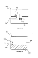
- video screens 101 have been mounted in the headrests 102 of vehicles, facilitating video entertainment on the road. These video screens are connected to video players located, for example, in the glove box of the vehicle.
- a video display system comprises a base portion, a first hinge coupled to the base portion, an arm including a first end coupled to the first hinge, wherein the arm is movable about the first hinge, a second hinge coupled to a second end of the arm; and a display panel coupled to the second hinge, wherein the display is movable about the second hinge, the display panel comprising a display.
- the display panel may be latchable to the base portion, preventing movement of the display and arm.
- the display may face towards or away from the base portion in a latched position.
- the video display system may further comprise a docking station for securing the base portion.
- the docking station may comprise a control for releasing the display from a latched position, a control for releasing the base portion from the docking station, a door hinged along a side of the docking station for selectively concealing the video display system.
- the docking station may secure the base portion to a vehicle headrest.
- the video display system may further comprise a media player for receiving a media comprising data to be displayed by the display, and a bracket for securing the base portion to a surface, the bracket comprising a hinge coupled to a first point of the base portion and a latch for selectively securing a second point of the base portion.
- the first hinge may be positioned along an edge of the base portion and the second hinge positioned at a point between two opposing edges of the display panel.
- a video system comprises a base portion mounted in a vehicle seat headrest, and a door pivotally attached to the base portion, wherein the door includes a display and a media player mounted to the door.
- the media player may be a slot-type device or a clamshell-type device.
- the base portion may be coupled to an internal headrest support structure or attached directly to the body of the headrest.
- the video system may further comprise a port for connecting to an external device, and a wireless transmitter for transmitting wireless signals on more than one channel, wherein the wireless signals include at least one of audio signals and video signals.
- the display may be mounted on a front side of the door and the media player may be mounted on a backside of the door.
- the door may pivot in a range of angles including approximately 0° to 180° with respect to the base portion.
- the door may be pivotally attached to the base portion with a hinge.
- the display and the media player may be capable of operating when the door is in a closed position, and a data storage medium may be inserted into the media player when the door is in an open position.
- the vehicle seat headrest may include at least one vent for dissipating heat.
- the media player may include at least one of a DVD player, a CD-ROM player, a video game player, a videocassette player, a television tuner, a radio tuner, and a device capable of playing at least one of computerized video files and computerized audio files.
- a video system comprises a base portion mounted in a vehicle seat headrest, wherein the base portion includes a media player mounted in the base portion, and a door pivotally attached to the base portion, wherein the door includes a display mounted to the door.
- an entertainment system comprises a media source, and a housing for supporting the media source, wherein the housing is coupled to an inner portion of a seat of a vehicle, and the media source is capable of being selectively connected to and disconnected from the housing.
- the media source may include at least one of a DVD player, a CD-ROM player, a video game player, a videocassette player, a television tuner, a radio tuner, an MP3 player, and a digital video recorder.
- the housing may be mounted in one of a headrest and a main body of the seat and may include a cavity for receiving the media source.
- the media source may include a port for connecting to an external device, and a wireless transmitter for transmitting wireless signals, wherein the wireless signals include at least one of audio signals and video signals.
- the entertainment system may further comprise a display operatively coupled to the media source, wherein the display is one of handheld, mounted to the housing and mounted at a location in the vehicle away from the housing.
- the display may be operatively coupled to the media source via at least one of a direct connection, a connection through the housing or a wireless connection.
- the media source may be electrically coupled to the housing using a pin array.
- the entertainment system may further comprise a door pivotally attached to the housing with a hinge, wherein the hinge is positioned at a top, bottom or side portion of the door.
- a display may be mounted on the door.
- the seat of the vehicle includes may include an opening in line with a slot in the media source for receiving a data media to be inserted in the slot.
- the media source may include a storage device capable of storing at least one of a plurality of audio files and a plurality of video files.
- a docking station for supporting a removable video system comprises a connector for electrically coupling the docking station to the removable video system, and at least one port for connecting a media source to the docking station, wherein data from the media source is provided to the docking station via the at least one port and to the removable video system via the connector.
- the at least one port may be one of a universal serial bus port, an audio input port, a video input port and an audio/video input port.
- the data may include at least one of audio data and video data.
- the media source may be one of an MPEG player, a card reader, a DVD player, a CD-ROM player, a video game player, a videocassette player, or a digital video recorder.
- the docking station may receive a media storage medium and data from the media storage medium may be provided to the removable video system via the connector.
- the docking station may further comprise a television tuner, wherein a program received by the television tuner is provided to the removable video system via the connector.
- the docking station may be mounted in an interior portion of a vehicle, to one of a ceiling, a wall or a piece of furniture, or the docking station may be free standing.
- the docking station may further comprise a stationary portion and a swinging portion attached to the stationary portion, wherein the removable video system is secured to the swinging portion.
- the docking station may be connectable to a battery and/or may include a port for connecting to an adapter for a power supply.
- the removable video system may include a display capable of displaying video data received from the docking station.
- the removable video system may also include a media player capable of playing media stored on at least one of a digital video disc, a compact disc, a video compact disc, a flash card, a secure digital card, a smart media card and a memory stick card.
- the removable video system may be capable of operating when remote from the docking station, and/or capable of connecting to at least one of a battery and an adapter for a power supply.
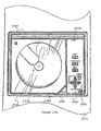
- the portable video system can be embodied as a slot-type video system 301 comprising a slot 302 that receives a data media into a mechanism for accessing data stored on the medium, such as a digital videodisk (DVD) player, MPEG player 3 (MP3) disk, or video game disk.
- the video system 301 is secured to a docking station 303.
- the video system 301 comprises a hinge 304. The hinge connects a video screen portion of the video system to a base portion of the video system.
- the docking station 303 is secured in the headrest 102, and more particularly to an internal headrest support structure 305.
- the docking station 303 can be secured by, for example, a catch 401 as shown in Figure 4A and/or a screw 402 as shown in Figure 4B .
- a catch 401 as shown in Figure 4A
- a screw 402 as shown in Figure 4B .
- One of ordinary skill in the art would recognize that other means of securing the docking station can be used, for example, an adhesive compound.
- the docking station 303 secures a base portion of the video system 301, and allows a video screen portion 306 to pivot away from the base portion.
- the slot 302 is exposed for receiving a data media when the video screen portion 306 is in a pivoted position away from the base portion of the video system 301.
- the video system 301 can be disconnected from the docking station 303 (cut away view).
- the video system 301 can be operated autonomously. That is, when decoupled from the docking station 303, the video system 301 can access a data media to play, for example, a movie.
- the video system can operate on power supplied by an optional battery or a connection to an external power supply, such as an AC or DC current.
- the connection can be to the base portion 307 of the video system 301.
- a headrest 308 can comprise an opening 309 for receiving a data media into the video system 301.
- the video system 301 can be a permanently installed or portable video system.
- the headrest opening 309 aligns with the slot 302 of the video system 301 to allow data media, such as a DVD or MP3 disk to be inserted from the side, top, or bottom of the headrest 308.
- the headrest 308 further comprises vents 310 for dissipating heat.
- a cooling fan 311 for increasing airflow can also be added within the headrest.
- the cooling fan 311 can be located in the headrest 308 and behind the vent 310, such that the cooling fan 311 is concealed.
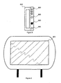
- a portable video system 501 of a clamshell-type is secured to a docking station.
- the portable video system 501 comprises a door 502 and a base portion 503 connected by a hinge 504.
- the door 502 pivots away from the base portion 503 on the hinge 504.
- the hinge 504 can be positioned on any side of the door 502.
- the door 502 comprises a video screen 505, controls 506A, and an infrared (IR) transmitter and/or receiver 507.
- the video system 501 receives a data media 508 comprising data to be accessed. When the door 502 is closed the data media 505 is secured.
- the door 502 can be opened by, for example, depressing a button releasing the door 503 from the base portion 503 or pulling the door 502 away from the base 503 wherein the hinge 504 is a friction fitting.
- a media player 509 is concealed by cover 510.
- the cover 510 can be opened by, for example, depressing a button 511.
- the video system 501 is removable, such that the video system can be disconnected from the docking station 303.
- the base 503 comprises a control panel 506B.
- the control panel 506B comprises a plurality of controls for controlling the functions of the media player, for example, volume control, previous, next, pause, eject and play, and a power on/off button.
- the controls 506A and 506B can be, for example, buttons, switches, a touch sensitive liquid crystal display, and the like.
- the docking station 303 comprises a pin array 601 for connecting to a pin array 602 of a video system 603.
- the video system 603 can be a slot-type device, a clamshell-type device, or any other device that is capable of being secured in the docking station 303.
- the pin array 601 and video system pin array 602 transfer data to and from the video player 603.
- the video player can be connected to external devices through the docking station 303.
- the external devices include, for example, a slave video display unit installed in another headrest, a security system, and a vehicle sound system.
- the docking station can be omitted, and a connection to the vehicle's power supply and/or data bus can be directly coupled to the video system 603 through, for example, an electrical harness.
- the docking station 303 is coupled to a vehicle's electrical system.
- the docking station 303 is connected to a vehicle's power supply, e.g., 12 Volts, through a wiring harness. Power can be supplied to the video system 603 through the pin arrays 601 and 602.
- the docking station 303 can be connected to a vehicle's data communication bus.
- the data communications bus can carry data to and from the external devices.
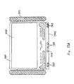
- the docking station 303 comprises a quick release mechanism for securing and releasing the video system 701.
- the quick release mechanism can include a button 702 for releasing a latch 703, which is secured to the video system 701 by pressing the video system 701 securely into the docking station 303.
- a latch mechanism comprises a latch 703 that passes into a bottom portion of the video system 701. The latch 703 is momentarily displaced as the video system 701 is coupled with the docking station 303.
- a spring 704 secures the latch 703 in the bottom portion of the video system 701.
- the button 702 can be pressed, aligning the latch 703 with an opening in the bottom portion of the video system 701, and the video system 701 can be pulled away from the docking station 303.
- a rear portion 705 of the video system 701 can be secured by a convex portion 706 that fits within a concave portion 707 in the docking station 303.
- a wall of the docking station 708 flexes away from the rear portion of the video player until the convex portion 706 is aligned with the concave portion 707.
- the convex portion 706 and the concave portion 707 cooperate to secure the video system 701 to the docking station 303.
- a wall of the docking station 708 can be formed of, for example, a flexible thermoplastic rubber.
- Other means of securing the video system 701 to the docking station 303 are contemplated, such as, snaps, locks, latches, and the like.
- the video system 801 comprises input and output ports.
- other port types can be provided, for example, a USB port or RCA jack for connecting to a game controller.
- the video system 801 comprises a wireless transmitter for transmitting, for example, an audio radio frequency, Bluetooth®, or Whitefire® signal to wireless headphones.
- the video system 801 further comprises an infrared (IR) port 805 for transmitting and/or receiving, for example, remote control signals.
- IR infrared
- the ports can be positioned at any convenient location on the video system 801, for example, on a bottom portion of the base of the video system, a front portion of the base of the video system, or a side portion.
- a cover 901 can conceal a portion of the docking station, as shown in Figure 9 .
- the cover 901 is manufactured from a material such as, plastic, wood, leather, and/or aluminum.
- the cover 901 can be secured by the same mechanisms as the video system, such as those shown in Figure 7A and 7B .
- the cover 901 and the video player can have one or more features in common, such as openings for receiving latches and the like.
- a portable video system is easily removable from and can be operated outside of a vehicle, for example, in home or office environments.
- the video system can be permanently connected to the headrest support structure by, for example, screws, catches, and adhesives.
- a video system 1001 and a video slave unit 1002 are connected to a power supply 1003.
- the video slave unit receives data to be displayed from the video system 1001 through a data bus 1004.
- the data bus 1004 can be connected to other devices 1005, such as a vehicle's sound system or a vehicle's navigation system.
- the connections between the video system 1001 and the external device(s) 1005 can be a wireless connection (not shown).
- the connection between the video system 1001 and the video system slave device 1002 can be a wireless connection (not shown).
- video system has been described in terms of a clamshell-type device and a slot-type device, the video system can be embodied in other configurations, for example, as a draw-type device comprising a draw and a spindle for securing the data media in place.
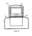
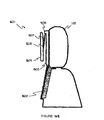
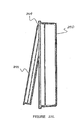
- a video system according to an embodiment of the present invention is a tablet-type device comprising a swivel-hinge connecting a video screen to a base portion as shown in Figures 11A and 11B .
- the swivel-hinge 1101 allows a door 1102 comprising a screen to move about two axes such that the screen 1102 can be swiveled about the swivel-hinge 1001 while in an open position, pivoted away from the base 1103.
- the screen can be turned to face the base portion 1103 when in a fully closed position (e.g., Figure 11B ) or turned to face away from the base portion 1103 in a closed viewing position (e.g., 11A). In both the fully closed position and the closed viewing position, the door 1102 is substantially parallel to the base portion 1103.
- the swivel-hinge 1101 can be implemented in a slot-type device or a clamshell-type device.
- an entertainment system 1200 includes a docking station 1203 and video system 1201 mounted to the docking station 1203.
- the docking station 1203 is preferably mounted in a vehicle to the vehicle ceiling 1250 and includes stationary and swinging portions 1207 and 1209.
- the docking station 1203 also may be mounted in another portion of a vehicle, such as to a wall or to a seat in the vehicle.
- the docking station 1203 can be mounted outside of a vehicle, such as under a kitchen cabinet or to a wall or ceiling in a home or office.
- the docking station includes holes 1208 and 1210 in the stationary portion 1207 through which screws 402 pass into a surface to which the docking station 1203 is mounted.
- the docking station 1203 may be mounted to a surface using clips 401, screws 402, brackets, adhesive, nails, rivets or any suitable mounting mechanism known to one of ordinary skill in the art.
- the docking station 1203 includes lights 1212 which can be turned on or off by user or wired to operate like standard overhead lighting when the docking station 1203 is mounted in a vehicle, such that the lights can be switched on or off and turn on automatically when a door of the vehicle is ajar.
- the function of the lights 1212 is controlled with a switch 1216.
- the video system 1201 mounts to the swinging portion 1209 of the docking station 1203 using, for example, a quick release mechanism or concave/convex portions the same or similar to those described in connection with Figures 7A and 7B .
- Other means of securing the video system 1201 in the docking station 1203 are contemplated, such as, snaps, locks, latches, and the like.
- an electrical connection between the video system 1201 and the docking station 1203 is provided through pin arrays 601 and 602.
- a pin array 602 of the video system 1201 is located on a rear portion ofthe video system housing. Data to and from the video system 1201, such as video and audio signals, is transferred through the pin arrays 601 and 602.
- power from the vehicle can be transmitted to the video system 1201 through the pin arrays 601 and 602.
- An electrical connection between the video system 1201 and the docking station 1203 may be provided through connectors other than pin arrays known to those of skill in the art for transferring audio and video signals and power.
- the swinging portion 1209 is coupled to the stationary portion 1209 with a hinge mechanism 1213 that allows the swinging portion 1209 to rotate about a horizontal axis between the stationary and swinging portions 1207 and 1209.
- the hinge mechanism 1213 allows the swinging portion 1209 to rotate approximately 180° and to lock in different positions at desired viewing angles of the screen 1220 of the video system 1201.
- a hinge mechanism allowing a more limited range of motion, for example, from about 0° to 90° may be used.
- the swinging portion 1209 closes against the stationary portion 1207 so as to conceal the video system 1201 and occupy less space when not in use.
- the swinging portion 1207 preferably locks in place with a latch mechanism that can be released by depressing a button 1214.
- the video system 1201 has the capability of playing video programs received through the docking station 1203.
- the docking station 1203 includes a TV tuner that receives television signals for broadcast by a video system mounted therein.
- a channel display 1260 and channel selector buttons 1261 for selecting a television channel are positioned on a side panel the docking station 1203, but may be positioned on other convenient portions of the docking station 1203.
- the docking station may include a radio tuner (not shown).
- the docking station 1203 also includes ports for connecting to external media devices, such as a universal serial bus (USB) port 1262 and input/output ports 1263.
- the ports 1262 and 1263 are used to connect devices, such as an MPEG player, a card reader, a DVD player, a CD-ROM player, a video game player, a videocassette player, and a digital video recorder.
- audio input ports include XLR and RCA jacks and video input ports include S-video connections, RCA connections, F-connections, and component video.
- the input/output ports 1263 also can include, for example, a headphone port and a power port.
- the docking station 1203 includes slots 1264 and 1265 of different sizes for receiving DVDs, CDs, flash cards, secure digital (SD) cards, smart media (SM) cards and memory stick (MS) cards. Accordingly, the docking station 1203 is capable of reading various types of media storage mediums and transferring audio and video data from the media storage medium to a video system 1201 connected thereto for broadcast on the video system 1201.
- media storage mediums can also be inserted into the docking station using a clamshell type design.
- a drawer type design may also be implemented whereby a holder for a media storage medium slides out of the docking station (like a drawer) to permit insertion of a media storage device in the holder.
- the docking station 1203 also includes a control switch 1218 for turning a display 1220 of the video system 1201 on and off and selector buttons 1219 for selecting a program from a desired media source for display. For example, a user may depress the selector buttons 1219 to select a program from an MPEG player to be displayed on the video system 1201.
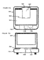
- a video system 1201 is connected to a tabletop docking station 1303.
- the docking station 1303 is free standing and may be placed on a desk, table or counter, for example.
- a quick release mechanism or concave/convex portions the same or similar to those described in connection with Figures 7A and 7B or other means, such as snaps, locks, latches, and the like, can be used to secure the video system 1201 to the docking station 1303.
- an electrical connection between the video system 1201 and the docking station 1303 for providing data and power between the docking station 1203 and the video system 1201 is provided through pin arrays 601 and 602 located on the docking station 1303 and the video system 1201, respectively.
- An electrical connection between the video system 1201 and the docking station 1303 may be provided through connectors other than pin arrays known to those of skill in the art for transferring audio and video signals and power.
- the docking station 1303 includes a USB port 1362 and various input/output ports 1363 for connecting to outside media devices, headphones and/or a power supply.
- the docking station 1303 includes a power port for connecting to a power supply through an AC/DC adapter.
- the docking station 1303 also may connect to a battery pack (not shown) similar to the battery pack 1501 shown in Figure 15 for powering the docking station 1303 and a video system 1201 connected thereto.
- the docking station 1303 includes slots 1364 and 1365 of different sizes for receiving media storage mediums such as DVDs, CDs, flash cards, secure digital (SD) cards, smart media (SM) cards and memory stick (MS) cards. Like the docking station 1203, clamshell and drawer type designs also may be used for insertion of media storage mediums in the docking station.
- the docking station 1303 is capable of reading various types of media storage mediums and transferring audio and video data from the media storage medium to a video system 1201 connected thereto for broadcast on the video system 1201.
- the ports 1362, 1363 and slots 1364, 1365 can be located on the front, side or rear of the docking station 1303.
- the docking station 1303 also includes speakers 1312 for broadcasting audio programs or audio associated with a video program.
- the docking station 1303 may include TV and radio tuners, a control switch 1318 for turning a display 1220 of the video system 1201 on and off and selector buttons 1319 for selecting a program from a desired media source for display. For example, a user may depress the selector buttons 1319 to select a program from an MPEG player to be displayed on the video system 1201.
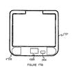
- the video system 1201 capable of being connected to a docking station 1203/1303 is shown.
- the video system 1201 includes a display 1220, which is preferably a liquid crystal display (LCD).
- the display 1220 can be.a cathode ray tube (CRT), gas plasma or organic electro-luminescent display (OELD) device.
- the size of the display is approximately 7 inches to approximately 12 inches.
- the video system includes ports for external media players, headphones or power and slots for receiving media storage mediums.
- the video system 1201 includes a USB port 1282 and input/output ports 1283.
- a control switch 1287 is set to IN or OUT controlling whether the ports are input or output ports. For example, if the control switch is set to IN, a device, such as a portable DVD player, can be connected to the video system 1201 via audio and video IN ports to allow for display of a video program from the portable DVD player on the video system 1201.
- the video system 1201 includes a power port for connecting to a power supply through an AC/DC adapter. Further, as shown in Figure 15 , the video system 1201 also may connect to a battery pack 1501 for powering the video system 1201. The connection between the video system 1201 and the battery pack 1501 is provided through respective pin arrays 1295 and 1595 located on the video system 1201 and battery pack 1501. The position of the pin array 1295 on the video system 1201 may vary depending on the number and location of ports and slots incorporated into the video system 1201. Connectors other than pin arrays known to those skilled in the art may also be used.
- the slots 1284 and 1285 are different sizes for receiving a variety of media storage mediums such as DVDs, CDs, video CDs (VCDs), flash cards, secure digital (SD) cards, smart media (SM) cards and memory stick (MS) cards.
- media storage mediums such as DVDs, CDs, video CDs (VCDs), flash cards, secure digital (SD) cards, smart media (SM) cards and memory stick (MS) cards.
- VCDs video CDs
- SD secure digital
- SM smart media cards
- MS memory stick
- clamshell and drawer type designs also may be used for insertion of media storage mediums in the video system 1201.
- the video system 1201 is capable of reading the various types of media storage mediums inserted therein for broadcast on the video system 1201.
- the ports 1282, 1283 and slots 1284, 1285 can be located on the front, side or rear ofthe video system 1201.
- the video system 1201 is capable of operating independent of the docking stations 1203/1303, relying on power supplied through a connection to a standard power supply (e.g., an adapter connected to a household outlet) or through the battery pack 1501.
- a standard power supply e.g., an adapter connected to a household outlet
- Media players such as a DVD player, are built into the video system 1201 or can connect to the video system 1201 via the ports 1282 and 1283.
- the video system 1201 When connected to a docking station 1203/1303, the video system 1201 is capable of receiving video and audio programs through the docking station 1203/1303 from media players connected to the docking station 1203/1303. Alternatively, the video system 1201 can broadcast video programs received from media players built into the video system 1201 or directly connected to the video system 1201 via ports 1282 and 1283. It should also be understood that a video display device, not having any media sources built into the video display device or connected thereto, can be connected to the docking station 1203/1303 and receive the video programs for broadcast through media players connected to the docking station 1203/1303.
- the video system 1201 includes speakers 1232 for broadcasting audio programs or audio associated with a video program. Like the docking stations 1203/1303, the video system 1201 may include TV and radio tuners.
- the video system 1201 includes a variety of control buttons 1290 controlling power, source, screen mode, picture selection and functions of a media source, such as stop, pause, previous, play and next.
- the control buttons 1290 enable a user to control display characteristics and which programs from which sources are displayed. Additional control buttons can include volume control and channel selection.
- a portable video system can be coupled to a vehicle headrest.
- the portable video system receives a data media comprising data to be displayed.
- the video system is secured to a docking station.
- the docking station can be mounted, for example, in a headrest of an automobile's seat or under a kitchen cabinet.
- the video system is removable, such that the video system can be disconnected from the docking station.
- a video system 1601 is mounted in a headrest 102.
- a door 1602 can protect the video system 1601.
- the door 1602 swings away from the headrest 102 to reveal the video system 1601.
- the door 1602 is coupled to the docking station by a hinge 1603 or other retaining means.
- the door 1602 can be closed to conceal the docking station.
- the video system 1601 comprises a video display panel 1604.
- the video display panel 1604 is coupled to a video system base portion 1605 by a hinge. More than one hinge can be provided.
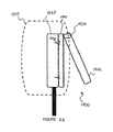
- a first hinge 1606 is provided to movably couple the video system base portion 1605 to an arm 1607.
- the arm 1607 is in turn movably coupled to the video display panel 1604 by a second hinge 1608.
- the first hinge 1606 is positioned along an edge of the base portion 1605.
- the second hinge 1608 is connected to the display panel 1604 a point between two opposing edges of the display panel, such that the display panel 1604 can be positioned against the base portion 1605 facing towards the base portion or away from the base portion 1605.
- the first hinge 1606 and second hinge 1608 operate in a plane perpendicular to the video system base portion 1605 allowing the display panel 1604 to move in an arc around the first hinge 1606.
- the display panel 1604 is simultaneously moveable on an arc about a first point of the base portion and a plurality of second points defined along the arc, wherein the arc is on a plane perpendicular to the base portion
- a hinge may provide movement in more than one axis.
- the second hinge 1608 may allow movement in the plane perpendicular to the video system base portion 1605 and in a left/right pan movement.
- a hinge may be a ball and socket type hinge allowing the display panel 1604 to be positioned in any of a plurality of planes.
- the video system 1601 can be permanently mounted or coupled to a docking station 1609 of the headrest 102.
- the docking station 1609 is secured in the headrest 102, and more particularly to an internal headrest support structure 1610.
- the docking station 1609 can be secured by, for example, a catch 401 as shown in Figure 4A and/or a screw 402 as shown in Figure 4B .
- a catch 401 as shown in Figure 4A
- a screw 402 as shown in Figure 4B
- the docking station 1609 secures a base portion 1605 of the video system 1601, and allows a video screen portion 1604 to move away from the base portion 1605.
- the video system 1601 can be disconnected from the docking station 1609 (cut away view).
- the video system 1601 can be operated autonomously. That is, when decoupled from the docking station 1609, the video system 1601 can access a data media to play, for example, a movie.
- the video system 1601 can operate on power supplied by an optional battery or a connection to an external power supply, such as an AC or DC current.
- the connection can be to the base portion 1605 of the video system 1601.
- a video system 1601 and docking station 1701 are shown.
- the video system 1601 is removable, such that the video system can be disconnected from the docking station 1701.
- the video system 1601 comprises a base portion 1605 and a display panel 1604.
- a base portion ofthe video system 1605 comprises a control panel 1702.
- the control panel 1702 comprises a plurality of controls for controlling the functions of the media player, for example, volume control, previous, next, pause, eject and play, and a power on/off button.
- the controls can be, for example, buttons, switches, a touch sensitive liquid crystal display, and the like.
- the base portion comprises a door 1703 concealing a media player, e.g., a DVD or CD-ROM player.
- the docking station 1701 comprises a control 1704 for releasing the video system 1601 and a control 1705 for releasing the display panel 1604 independent of the base portion 1605, such that the display panel 1604 may be opened while the video system 1601 is docked.
- the control 1705 for releasing the display panel 1604 operates a latch or other retaining means that retains the display panel 1604 to the base portion 1605.
- the docking station 1701 may also comprise additional elements such as courtesy lights 1706, audio/visual ports, remote control signal receivers, etc.
- the first hinge 1606 and second hinge 1608 are connected to the arm 1607.
- the arm 1607 in combination with the first hinge 1606 and second hinge 1608, couple the display panel 1604 to a base portion of the video system docked in the docking station 1701.
- the display panel 1604 comprises a display 1709 for rendering data.
- the display panel 1604 is closed, e.g., latched to the base portion, the display 1709 may be visible or may be protected by a back portion 1710 of the display panel 1604.
- the display panel 1604 can be latched to the base portion with the display facing towards the base portion for storage or away from the base portion for viewing.
- a docking station 1701 like the docking station 303 shown in Figure 6A , is coupled to a vehicle's electrical system.
- the docking station 1701 is connected to a vehicle's power supply, e.g., 12 Volts, through a wiring harness.
- a vehicle's power supply e.g. 12 Volts
- power can be supplied to the video system 1601 through the pin arrays 601 and 602.
- the docking station 1701 can be connected to a vehicle's data communication bus.
- the data communications bus can carry data to and from the external devices.
- the docking station 1701 comprises a quick release mechanism as shown in Figure 7A , or a concave portion 707 for mating with a convex portion 706, as shown in Figure 7B , for securing and releasing the video system 1601.
- a portable video system is easily removable from and can be operated outside of a vehicle, for example, in home or office environments.
- the video system can be permanently connected to the headrest support structure by, for example, screws, catches, and adhesives.
- a video system 1601 may be installed on a surface, such as under a shelf or on a desk.
- the video system 1601, including the display and base portion, can be coupled to a bracket 1801.
- the bracket 1801 comprises a base portion including a hinge 1802 and a latch 1803, and an arm portion 1804 coupled to the hinge 1802 and able to swing away from the surface 1805 when disconnected from the latch 1803. Coupled to the arm portion 1804, the video system 1601 can swing away from the surface 1805.
- the video system 1601 may be coupled to the bracket by a docking station 1701, facilitating the removal of the video system 1601. Where a docking station 1701 is implemented, the docking station is coupled to the portion of the bracket that is movable away from the surface 1805.
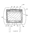
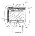
- the video system 1900 mounted in a headrest 1901 includes a door 1902 is connected via a hinge or hinges 1904 to a base portion 1910.
- the door 1902 includes an entertainment unit 1950 and a display 1920 formed on opposite sides thereof.
- the entertainment unit 1950 and other entertainment units described herein may include, for example, a DVD player, a CD-ROM player, a video game player, a videocassette player (VCP), a television or radio tuner, an MP3 player or similar device capable of downloading and playing computerized video and/or audio files, or any combination of the above media sources.
- a connection between the display 1920 and the entertainment unit 1950 may be achieved through appropriately positioned openings in the door 1902.
- the door 1902 may consist of an open center section surrounded by a frame, wherein the display 1920, including the entertainment unit 1950 coupled to its rear, snugly fits into the open center section bordered by the frame.
- the display 1920 and the entertainment unit 1950 can be fixed to the door 1902 by, for example, screws, catches, adhesives, molding, pressure fitting and/or any other means known to those skilled in the art.
- the base portion 1910 can be fixed to the headrest 1901 by, for example, screws 402, catches 401, adhesives, epoxies and/or any other means known to those skilled in the art.
- the base portion is secured in the headrest 1901, and more particularly to an internal headrest support structure 1925.
- the base portion may be attached (e.g., glued or riveted) directly to the body of the headrest.
- the hinge 1904 located at a top portion of the door 1902, allows the door 1902 to pivot away from the base portion 1910 to expose a slot 1952 in the slot-type entertainment device 1950 for receiving a data media 1955, such as a DVD.
- the hinge 1904 may be positioned at top, side or bottom portions of the door 1902, and depending on the location of the hinge 1904, the slot 1952 may be positioned at top, side or bottom portions of the entertainment device 1950.
- the door 1902 may be opened, for example, by pulling a tab 1903 and/or by depressing a button (not shown) releasing the door 1902 from the base portion 1910.
- the door 1902 may be closed by re-engaging the released side of the door 1902 with the base portion 1910. A desired program can be played for viewing while the door 1902 is in the closed position.
- the display 1920 has a thin display screen, preferably an LCD type screen, for displaying video information.
- a control panel 1980 on the display 1920 includes control buttons 1981 for controlling the on screen display characteristics.
- the display 1920 may include input and output ports.
- other port types can be provided, for example, a USB port or RCA jack for connecting to a game controller or headphones.
- the ports can be positioned at any convenient location on the video system 1900, for example, on a bottom portion, a top portion, or a side portion of the video system 1900.
- a speaker (not shown) for presenting audio information in connection with a video program being played can be mounted in the headrest 1901, or to the door 1902, base portion 1910, the display 1920, or the entertainment unit 1950. Alternatively, audio may be provided to vehicle occupants through the existing vehicle audio system.
- the display 1920 may include a wireless transmitter 1995 for transmitting wireless signals to wireless receivers in wireless headphones.
- the wireless signals may include radio frequency signals for use with, for example, Bluetooth® wireless systems or infrared (IR) signals for use with, for example, Whitefire® systems. It is preferred that the wireless transmitter 1995 has the capability to transmit wireless signals over more than one channel operating at a different frequency for each channel. The use of more than one channel, for example, avoids interference between more than one wireless headphone user watching different programs on different displays. Wireless signals also may be encoded to prevent interference between wireless headphones. Such encoding may be based on, for example, spread spectrum technology.
- the wireless transmitter 1995 can include an optical transmitting device (e.g., an LED, a laser, and so forth) and an antenna for wireless transmission of IR signals and RF signals, respectively.
- the video system 1900 can be connected to a vehicle's power supply, e.g., 12 Volts, through a wiring harness.
- the video system 1900 can also be connected to a vehicle's data communication bus, which carries data to and from the external devices.
- the video system 1900 can be connected to external devices including, for example, a slave video display unit installed in another headrest, a security system, and a vehicle sound system.
- Controls 1956 for controlling functions of the entertainment device 1950 may be positioned on the door 1902, display 1920, and/or the entertainment device 1950.
- the controls 1956 can be, for example, buttons, switches, a touch sensitive liquid crystal display and the like.
- Figures 20A-20E show another embodiment of a video system 2000 installed in a headrest 2001, wherein an entertainment unit 2050 is integrated into the headrest 2001 along with the display 2020.
- a door 2002 is connected via a hinge or hinges 2004 to the base portion 2010.
- the door 2002 includes the display 2020 and the entertainment unit 2050 formed on opposites sides thereof, like the door 1902 and the entertainment unit 1950 of the previously described embodiment.
- the display 2020 and the entertainment unit 2050 can be fixed to the door 2002 and the base portion 2010 can be fixed to the headrest 2001 by the same or similar means to those previously described in connection with the headrest 1901.
- the hinge 2004, located at a top portion of the door 2002 allows the door 2002 to pivot 180° away from the base portion 2010 to expose a cover 2052 of a clamshell-type entertainment device 2050 that can be opened to allow insertion of a data media, such as a DVD, into the entertainment device 2050.
- a hinge 2004 that allows the door 2002 to pivot more or less than 180° can be used provided that easy opening of the cover 2052 and subsequent insertion or removal of a data media from the entertainment unit 2050 can be achieved.
- the hinge 2004 may be positioned at top, side or bottom portions of the door 2002.
- the door 2002 may be opened, for example, by pulling a tab 2003.
- a button (not shown) may be depressed releasing the door 2002 from the base portion 2010.
- the cover 2052 may be opened, for example, by pulling a tab (not shown) and/or by depressing a button 2053 releasing the cover 2052 from the entertainment unit 2050.
- the door 2002 may be closed by re-engaging the released side of the door 2002 with the base portion 2010. A desired program can be played for viewing while the door 2002 is in the closed position.
- the display 2020 has a thin display screen, preferably an LCD type screen, and may include a control panel 2080 with control buttons 2081 for controlling the on screen display characteristics.
- a wireless transmitter 2095 and input/output ports 2082-2085 may be positioned at any convenient location on the door 2002, the display 2020 or the base portion 2010.
- audio may be provided to vehicle occupants through the existing vehicle audio system or through a speaker mounted in the headrest 2001 or entertainment unit 2050, or to the door 2002, base portion 2010 or display 2020.
- speakers 2057 are shown mounted in the entertainment unit 2050.
- the video system 2000 also may be connected to a vehicle's power supply and to external devices.
- controls 2056 for controlling functions of the entertainment device 2050 may be positioned on the door 2002, display 2020, and/or the entertainment device 2050.
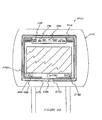
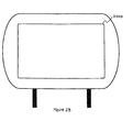
- Figures 21A-21D show another embodiment of a video system 2100 installed in a headrest 2101, wherein an entertainment unit 2150 is integrated into the headrest 2101 along with the display 2120.
- a door 2102 is connected via a hinge or hinges 2104 to the base portion 2110.
- the door 2102 includes the display 2120 formed on a front side thereof.
- the display 2120 can be fixed to the door 2102 by, for example, screws, catches, adhesives, molding, pressure fitting, snugly fitting into an open center section of the door 2102 bordered by a frame and/or any other means known to those skilled in the art.
- the base portion 2110 can be fixed to the headrest 2101 by the same or similar means to those previously described in connection with other embodiments.
- the hinge 2104 located at a top portion of the door 2102, allows the door 2102 to pivot away from the base portion 2110 to expose a clamshell-type entertainment device 2150 positioned in the base portion 2110.
- the entertainment device 2150 can be fixed to the base portion 2110 by any acceptable means known to those skilled in the art, such as by screws, catches, adhesives, molding and pressure fitting.
- the entertainment unit 2150 may also be selectively housed in the base portion 2110 so that it is replaceable with a different entertainment unit operating with the same or a different type of media.
- the entertainment device 2150 includes a cover 2152 that can be opened to allow insertion of a data media, such as a DVD, into the entertainment device 2150.
- the hinge 2104 may be positioned at top, side or bottom portions of the door 2102.
- the door 2102 may be opened, for example, by pulling a tab 2103.
- a button (not shown) may be depressed releasing the door 2102 from the base portion 2110.
- the cover 2152 may be opened, for example, by pulling a tab (not shown) and/or by depressing a button 2153 releasing the cover 2152 from the entertainment unit 2150.
- the door 2102 may be closed by re-engaging the released side of the door 2102 with the base portion 2110. A desired program can be played for viewing while the door 2102 is in the closed position.
- the display 2120 has a thin display screen, preferably an LCD type screen, and may include a control panel 2180 with control buttons 2181 for controlling the on screen display characteristics.
- a wireless transmitter 2195 and input/output ports 2182-2185 may be positioned at any convenient location on the door 2102, the display 2120 or the base portion 2110.
- audio may be provided to vehicle occupants through the existing vehicle audio system or through a speaker mounted in the headrest 2101 or entertainment unit 2150, or to the door 2102, base portion 2110 or display 2120.
- the video system 2100 also may be connected to a vehicle's power supply and to external devices.
- controls 2156 for controlling functions of the entertainment device 2150 may be positioned on the door 2102, display 2120, and/or the entertainment device 2150.
- controls 2156 are shown in Figure 21D positioned on the entertainment device 2150.
- a cover 2300 can conceal the video system, as shown in Figure 23 .
- the cover 2300 is manufactured from a material such as, plastic, wood, leather, vinyl, cloth, and/or aluminum. Depending on the cover material, the cover 2300 can be secured by latches, catches, snaps, Velcro, and/or a zipper.
- the cover 2300 may include openings for receiving latches and the like.
- an entertainment system 2400 is shown, wherein a housing 2402 for a media source 2450 is integrated into a vehicle seat 2401 at, for example, the main body 2403 of the seat 2401.
- an entertainment system 2500 includes a housing 2502 for a media source 2550 that is integrated into the headrest 2505 of a vehicle seat 2501.
- the media sources 2450, 2550 may include, for example, a DVD player, a CD-ROM player, a video game player, a videocassette player (VCP), a television or radio tuner, and an MP3 player, digital video recorder (DVR) or similar device capable of downloading, recording, storing (e.g., on a storage device, such as a hard disk) and/or playing video and/or audio files or programs.
- the media sources 2450, 2550 may also include any combination of the above media sources.
- the media source can be a clamshell-type device, wherein a data media is inserted into the media source through a cover, for example, positioned on the top of the device ( Figure 27D ), a slot-type device, wherein a data media is inserted through a slot in the media source, a drawer-type device including a drawer and a spindle for securing a data media in place, or any other device configured to receive a data media.
- the housings 2402, 2502 can be fixed to the vehicle seats 2401, 2501 by, for example, screws 402, catches 401, adhesives, epoxies and/or any other means known to those skilled in the art.
- the housing 2502 can be secured to an internal support structure 2525 of the headrest 2505.
- the housing 2402 may be secured to internal structures 2425, 2426 of the main body 2403 of the vehicle seat 2401.
- the housings 2402, 2502 may be attached (e.g., glued or riveted) to a portion of the upholstery within the seat body or headrest.
- the media sources 2450, 2550 can be permanently fixed in a cavity or open portion 2410, 2510 of the housings 2402, 2502 by any acceptable means known to those skilled in the art, such as by screws, catches, adhesives, molding and pressure fitting.
- the media sources 2450, 2550 are preferably capable of being selectively inserted and mounted in the cavities 2410, 2510 and removable therefrom.
- the media sources 2450, 2550 may be selectively housed in the cavities 2410, 2510 so that they are replaceable with different media sources operating with the same or different types of media.
- the housings 2402, 2502 may include a quick release mechanism as shown in Figure 7A , or a concave portion 707 for receiving a convex portion 706, as shown in Figure 7B , for securing and releasing the media sources 2450, 2550.
- a wall of the housing 2402, 2502 located in the cavity 2410, 2510 includes a pin array 601 for connecting to a pin array 602 located on the media source 2450, 2550.
- the pin array 601 and media source pin array 602 transfer data to and from the media source 2450, 2550.
- the media source can be connected to external devices through the housing 2402, 2502.
- the external devices include, for example, a slave video display unit installed in another part of the vehicle, a security system, and a vehicle sound system.
- the media source 2450, 2550 may also be connected to the vehicle's power supply through the housing 2402, 2502.
- the housing 2402, 2502 can be coupled to a vehicle's electrical system and connected to a vehicle's power supply, e.g., 12 Volts, through, for example, a wiring harness. Power can be supplied to the media source 2450, 2550 through the pin arrays 601 and 602.
- the housing 2402, 2502 can also be connected to a vehicle's data communication bus, which can carry data to and from the external devices.
- a headrest 308 may include an opening 309 for receiving a data media to be inserted in the media source (e.g., media source 2450 or 2550).
- the media source e.g., media source 2450 or 2550.
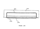
- an entertainment system 2700 is installed in a vehicle seat 2701, wherein a housing 2702 for a media source 2750 is integrated into the vehicle seat 2701, at, for example, the headrest or the main body of the vehicle seat 2701.
- a display 2720 is also attached to the housing 2702.
- the housing 2702 is attached to the seat 2701 and the media source 2750 is mounted in the housing 2702 in the same or similar manner as embodiments shown in Figures 24 and 25 .
- the media source 2750 may also include any of the devices listed above in connection with the media sources 2450 and 2550.
- the housing 2702 may include the pin array 601 for mating with a pin array 602 on the media source 2750 for transfer of power and/or data.
- a door 2730 is connected via a hinge or hinges 2732 to the housing 2702.
- the door 2730 includes the display 2720 formed on a front side thereof.
- the display 2720 can be fixed to the door 2730 by, for example, screws, catches, adhesives, molding, pressure fitting, snugly fitting into an open center section of the door 2730 bordered by a frame and/or any other means known to those skilled in the art.
- the hinge 2732 located at a top portion of the door 2730, allows the door 2730 to pivot away from the housing 2702 to expose a cavity 2710 for receiving and supporting the media source 2750 in the housing 2702.
- the hinge 2732 may be positioned at top, bottom or side portions of the door 2730 as long the door 2730 can be opened to expose the cavity 2710 for receiving the media source 2750.
- the media source 2750 includes a cover 2752 that can be opened to allow insertion of a data media, such as a DVD, into the media source 2750.
- the door 2730 may be opened, for example, by pulling a tab 2734.
- a button (not shown) may be depressed releasing the door 2730 from the housing 2702.
- the cover 2752 may be opened, for example, by pulling a tab (not shown) and/or by depressing a button 2754 releasing the cover 2752 from the entertainment unit 2750.
- the door 2730 may be closed by re-engaging the released side of the door 2730 with the housing 2702. A desired program can be played for viewing while the door 2730 is in the closed position.
- Controls 2760 for controlling functions of the media source 2750, such as, volume, previous, next, pause, eject, play and power on/off, are shown in Figure 27D positioned on the media source 2750.
- the display 2720 has a thin display screen, preferably an LCD type screen. Specifications for the display 2720 may include a TFT color liquid crystal display with a diagonal length of 4-8 inches, and a color TFT active matrix display.
- the display 2720 may include a control panel 2740 with control buttons 2742 for controlling the on screen display characteristics and input and output ports 2743 for items such as external devices or headphones.
- the media source 2750 may also include input and output ports positioned thereon.
- a display such as the display 2720, may also be attached to the housings 2402, 2502, either via a door or directly to the housings using fasteners, screws, catches, molding, snap-fit mechanisms or the like.
- a display may also be handheld, mounted in another portion of the vehicle away from the seat mounted media source, such as to a wall of the vehicle (e.g. the ceiling of the vehicle), on another seat or on a different portion of the same seat as the media source (e.g., on a headrest, while the media source is positioned on the main body of the seat).
- the display can be operatively coupled to the media source directly via wires or some other electrical connectors, or through the housing, via, for example, electrical connectors coupled to the pin array 601.
- Transfer of data may be obtained through the pin arrays 601, 602.
- video data from a DVR media source may be transferred through the pin arrays 601, 602 to a display coupled to the housing for producing a video image on a display screen.
- audio data may be transferred through the pin arrays 601, 602 to a display, speakers and/or headphones coupled to the housing for producing sound associated with a video image.
- audio data may be sent through the display to speakers or headphones via wired or wireless transmission.
- Video and audio data may also be transferred to displays, speakers and/or headphones directly from the media source. Audio and/or video data from any of the above described media sources can be transferred via the pin arrays 601, 602 or through some other physical connection, such as wires or through wireless transmission to displays, speakers and/or headphones.
- the display 2720 or the media source 2750 may include a wireless transmitter 2775 for transmitting wireless signals to wireless receivers in wireless headphones via, for example radio frequency (RF) or infrared (IR) signals, using an antenna or optical transmitting device, respectively.
- the wireless transmitter 2775 can be capable of transmitting wireless signals over more than one channel operating at a different frequency for each channel so that interference between more than one wireless headphone user watching different programs can be avoided. Audio may also be provided to vehicle occupants through the existing vehicle audio system or through a speaker mounted in the seat 2701 or media source 2750.
- a cover can conceal the housing and cavity.
- the cover is manufactured from a material such as, plastic, wood, leather, vinyl, cloth, and/or aluminum. Depending on the cover material, the cover can be secured by the same mechanisms shown in Figures 7A-7B , or with catches, snaps, Velcro, and/or a zipper.
- the cover and the media source can have one or more features in common, such as openings for receiving latches and the like.
- a media source 2450, 2550 and/or 2750 is easily removable from and can be operated outside of a vehicle, for example, in home or office environments.
- Specifications for the displays may include a TFT color liquid crystal display with a diagonal length of 4-8 inches, and a color TFT active matrix display.
- the dimensions of the video systems to be installed in the headrests, including the base portion, may be approximately 150-250mm wide, 125-175mm long and 30-60mm thick.
Applications Claiming Priority (5)
| Application Number | Priority Date | Filing Date | Title |
|---|---|---|---|
| US10/688,611 US7679578B2 (en) | 2003-05-15 | 2003-10-17 | Headrest mountable video system |
| US10/699,334 US6899365B2 (en) | 2003-05-15 | 2003-10-31 | Seat mountable entertainment system |
| US10/749,443 US7149078B2 (en) | 2003-05-15 | 2003-12-31 | Video display system |
| US10/808,659 US7609946B2 (en) | 2003-05-15 | 2004-03-25 | Portable video system |
| EP04795518A EP1682973A4 (de) | 2003-10-17 | 2004-10-14 | Mobiles unterhaltungssystem |
Related Parent Applications (1)
| Application Number | Title | Priority Date | Filing Date |
|---|---|---|---|
| EP04795518A Division EP1682973A4 (de) | 2003-10-17 | 2004-10-14 | Mobiles unterhaltungssystem |
Publications (2)
| Publication Number | Publication Date |
|---|---|
| EP2698286A1 true EP2698286A1 (de) | 2014-02-19 |
| EP2698286B1 EP2698286B1 (de) | 2017-10-11 |
Family
ID=34468498
Family Applications (2)
| Application Number | Title | Priority Date | Filing Date |
|---|---|---|---|
| EP13182344.5A Not-in-force EP2698286B1 (de) | 2003-10-17 | 2004-10-14 | Mobiles Unterhaltungssystem |
| EP04795518A Withdrawn EP1682973A4 (de) | 2003-10-17 | 2004-10-14 | Mobiles unterhaltungssystem |
Family Applications After (1)
| Application Number | Title | Priority Date | Filing Date |
|---|---|---|---|
| EP04795518A Withdrawn EP1682973A4 (de) | 2003-10-17 | 2004-10-14 | Mobiles unterhaltungssystem |
Country Status (3)
| Country | Link |
|---|---|
| EP (2) | EP2698286B1 (de) |
| CA (1) | CA2543034C (de) |
| WO (1) | WO2005038628A2 (de) |
Families Citing this family (9)
| Publication number | Priority date | Publication date | Assignee | Title |
|---|---|---|---|---|
| US7044546B2 (en) | 2002-08-14 | 2006-05-16 | Johnson Safety, Inc. | Headrest-mounted monitor |
| US6871356B2 (en) | 2002-10-28 | 2005-03-22 | Johnson Safety, Inc. | Mobile video system |
| NL1029895C2 (nl) * | 2005-09-07 | 2007-03-08 | Bernardus Nicolaas Van De Laan | Hoofdsteun voor een stoel, en stoel voorzien van een dergelijke hoofdsteun. |
| US7762627B2 (en) | 2005-11-02 | 2010-07-27 | Chung Lung Chang | Headrest-mounted entertainment systems |
| WO2007081737A2 (en) * | 2006-01-04 | 2007-07-19 | Audiovox Corporation | Receiver and distribution unit for vehicle entertainment system |
| US8713613B2 (en) | 2006-01-04 | 2014-04-29 | Voxx International Corporation | Data distribution unit for vehicle entertainment system |
| US8141948B2 (en) * | 2007-05-11 | 2012-03-27 | Audiovox Corporation | Seat back entertainment system |
| DE102009045095C5 (de) | 2009-09-29 | 2019-04-18 | Fresenius Medical Care Deutschland Gmbh | Gehäuse mit Verschlussklappe |
| DE102014221155B3 (de) | 2014-07-10 | 2015-12-24 | Johnson Controls Gmbh | Kopfstütze für ein Fahrzeug |
Citations (6)
| Publication number | Priority date | Publication date | Assignee | Title |
|---|---|---|---|---|
| US5267775A (en) * | 1991-10-03 | 1993-12-07 | B/E Avionics, Inc. | System for mounting a monitor |
| US20020163215A1 (en) * | 2001-03-22 | 2002-11-07 | Emerling David M. | Vehicle console assembly |
| FR2829980A1 (fr) * | 2001-09-26 | 2003-03-28 | Security Vision Concept | Procede de montage d'un boitier sur un coussin muni d'une housse d'habillage, housse d'habillage equipee d'un boitier et le coussin revetu de cette housse |
| US20030137584A1 (en) * | 2001-10-29 | 2003-07-24 | Gene Norvell | Detachable vehicle monitor |
| EP1442936A1 (de) * | 2003-01-28 | 2004-08-04 | Sevic System Ag | Kasten zum Unterbringen einer Audio-Video-Einheit mit einer elektronischen Konsole wie z.B. Videolesegerät oder Spielkonsole und einem zugehörigem nicht integrierten Bildschirm |
| WO2004105373A2 (en) * | 2003-05-15 | 2004-12-02 | Audiovox Corporation | Headrest mountable video system |
Family Cites Families (9)
| Publication number | Priority date | Publication date | Assignee | Title |
|---|---|---|---|---|
| US4982996A (en) * | 1989-02-17 | 1991-01-08 | Fiat Auto S.P.A. | Automotive seating system featuring a television set |
| US5268817A (en) * | 1990-04-27 | 1993-12-07 | Kabushiki Kaisha Toshiba | Portable computer with keyboard and having display with coordinate input tablet rotatably mounted to face either toward or away from keyboard when closed over keyboard |
| KR19980025494A (ko) * | 1996-10-01 | 1998-07-15 | 김광호 | 액정디스플레이 모니터 스탠드 |
| US6266236B1 (en) * | 1997-08-27 | 2001-07-24 | Vadem | Apparatus and method for connecting and articulating display in a portable computer having multiple display orientations |
| EP1144222B1 (de) * | 1998-12-28 | 2004-09-29 | Johnson Controls Technology Company | Videoanzeigegerät für ein kraftfahrzeug |
| US6292236B1 (en) * | 1999-03-26 | 2001-09-18 | Rosen Products Llc | Automotive-ceiling-mounted monitor |
| JP2001255961A (ja) * | 2000-03-01 | 2001-09-21 | Internatl Business Mach Corp <Ibm> | コンピュータ及び冷却ファンの制御方法 |
| US6409242B1 (en) * | 2000-11-14 | 2002-06-25 | Chung L. Chang | Flat thin screen T/V monitor automotive roof mount |
| US6871356B2 (en) * | 2002-10-28 | 2005-03-22 | Johnson Safety, Inc. | Mobile video system |
-
2004
- 2004-10-14 EP EP13182344.5A patent/EP2698286B1/de not_active Not-in-force
- 2004-10-14 WO PCT/US2004/034371 patent/WO2005038628A2/en active Search and Examination
- 2004-10-14 CA CA2543034A patent/CA2543034C/en active Active
- 2004-10-14 EP EP04795518A patent/EP1682973A4/de not_active Withdrawn
Patent Citations (6)
| Publication number | Priority date | Publication date | Assignee | Title |
|---|---|---|---|---|
| US5267775A (en) * | 1991-10-03 | 1993-12-07 | B/E Avionics, Inc. | System for mounting a monitor |
| US20020163215A1 (en) * | 2001-03-22 | 2002-11-07 | Emerling David M. | Vehicle console assembly |
| FR2829980A1 (fr) * | 2001-09-26 | 2003-03-28 | Security Vision Concept | Procede de montage d'un boitier sur un coussin muni d'une housse d'habillage, housse d'habillage equipee d'un boitier et le coussin revetu de cette housse |
| US20030137584A1 (en) * | 2001-10-29 | 2003-07-24 | Gene Norvell | Detachable vehicle monitor |
| EP1442936A1 (de) * | 2003-01-28 | 2004-08-04 | Sevic System Ag | Kasten zum Unterbringen einer Audio-Video-Einheit mit einer elektronischen Konsole wie z.B. Videolesegerät oder Spielkonsole und einem zugehörigem nicht integrierten Bildschirm |
| WO2004105373A2 (en) * | 2003-05-15 | 2004-12-02 | Audiovox Corporation | Headrest mountable video system |
Also Published As
| Publication number | Publication date |
|---|---|
| WO2005038628A2 (en) | 2005-04-28 |
| EP1682973A2 (de) | 2006-07-26 |
| CA2543034C (en) | 2012-12-04 |
| EP1682973A4 (de) | 2011-06-08 |
| WO2005038628A3 (en) | 2007-07-19 |
| CA2543034A1 (en) | 2005-04-28 |
| EP2698286B1 (de) | 2017-10-11 |
Similar Documents
| Publication | Publication Date | Title |
|---|---|---|
| US7609946B2 (en) | Portable video system | |
| CA2525965C (en) | Headrest mountable video system | |
| CA2600461C (en) | Headrest mountable video system | |
| US7679578B2 (en) | Headrest mountable video system | |
| US6899365B2 (en) | Seat mountable entertainment system | |
| CA2584772C (en) | Seat mountable entertainment system | |
| US7149078B2 (en) | Video display system | |
| US6961239B2 (en) | Portable video system | |
| US7604273B2 (en) | Vehicle entertainment system | |
| US20060148576A1 (en) | Automobile entertainment system | |
| EP2698286B1 (de) | Mobiles Unterhaltungssystem | |
| CN100565425C (zh) | 移动娱乐系统 |
Legal Events
| Date | Code | Title | Description |
|---|---|---|---|
| AC | Divisional application: reference to earlier application |
Ref document number: 1682973 Country of ref document: EP Kind code of ref document: P |
|
| AK | Designated contracting states |
Kind code of ref document: A1 Designated state(s): AT BE BG CH CY CZ DE DK EE ES FI FR GB GR HU IE IT LI LU MC NL PL PT RO SE SI SK TR |
|
| PUAI | Public reference made under article 153(3) epc to a published international application that has entered the european phase |
Free format text: ORIGINAL CODE: 0009012 |
|
| 17P | Request for examination filed |
Effective date: 20140819 |
|
| RBV | Designated contracting states (corrected) |
Designated state(s): AT BE BG CH CY CZ DE DK EE ES FI FR GB GR HU IE IT LI LU MC NL PL PT RO SE SI SK TR |
|
| 17Q | First examination report despatched |
Effective date: 20150130 |
|
| GRAP | Despatch of communication of intention to grant a patent |
Free format text: ORIGINAL CODE: EPIDOSNIGR1 |
|
| STAA | Information on the status of an ep patent application or granted ep patent |
Free format text: STATUS: GRANT OF PATENT IS INTENDED |
|
| INTG | Intention to grant announced |
Effective date: 20170509 |
|
| GRAS | Grant fee paid |
Free format text: ORIGINAL CODE: EPIDOSNIGR3 |
|
| GRAA | (expected) grant |
Free format text: ORIGINAL CODE: 0009210 |
|
| STAA | Information on the status of an ep patent application or granted ep patent |
Free format text: STATUS: THE PATENT HAS BEEN GRANTED |
|
| AC | Divisional application: reference to earlier application |
Ref document number: 1682973 Country of ref document: EP Kind code of ref document: P |
|
| AK | Designated contracting states |
Kind code of ref document: B1 Designated state(s): AT BE BG CH CY CZ DE DK EE ES FI FR GB GR HU IE IT LI LU MC NL PL PT RO SE SI SK TR |
|
| REG | Reference to a national code |
Ref country code: GB Ref legal event code: FG4D |
|
| REG | Reference to a national code |
Ref country code: CH Ref legal event code: EP |
|
| REG | Reference to a national code |
Ref country code: FR Ref legal event code: PLFP Year of fee payment: 14 |
|
| REG | Reference to a national code |
Ref country code: IE Ref legal event code: FG4D |
|
| REG | Reference to a national code |
Ref country code: AT Ref legal event code: REF Ref document number: 935708 Country of ref document: AT Kind code of ref document: T Effective date: 20171115 |
|
| REG | Reference to a national code |
Ref country code: DE Ref legal event code: R096 Ref document number: 602004051918 Country of ref document: DE |
|
| REG | Reference to a national code |
Ref country code: NL Ref legal event code: MP Effective date: 20171011 |
|
| REG | Reference to a national code |
Ref country code: AT Ref legal event code: MK05 Ref document number: 935708 Country of ref document: AT Kind code of ref document: T Effective date: 20171011 |
|
| PG25 | Lapsed in a contracting state [announced via postgrant information from national office to epo] |
Ref country code: NL Free format text: LAPSE BECAUSE OF FAILURE TO SUBMIT A TRANSLATION OF THE DESCRIPTION OR TO PAY THE FEE WITHIN THE PRESCRIBED TIME-LIMIT Effective date: 20171011 |
|
| PG25 | Lapsed in a contracting state [announced via postgrant information from national office to epo] |
Ref country code: SE Free format text: LAPSE BECAUSE OF FAILURE TO SUBMIT A TRANSLATION OF THE DESCRIPTION OR TO PAY THE FEE WITHIN THE PRESCRIBED TIME-LIMIT Effective date: 20171011 Ref country code: FI Free format text: LAPSE BECAUSE OF FAILURE TO SUBMIT A TRANSLATION OF THE DESCRIPTION OR TO PAY THE FEE WITHIN THE PRESCRIBED TIME-LIMIT Effective date: 20171011 Ref country code: ES Free format text: LAPSE BECAUSE OF FAILURE TO SUBMIT A TRANSLATION OF THE DESCRIPTION OR TO PAY THE FEE WITHIN THE PRESCRIBED TIME-LIMIT Effective date: 20171011 |
|
| PG25 | Lapsed in a contracting state [announced via postgrant information from national office to epo] |
Ref country code: AT Free format text: LAPSE BECAUSE OF FAILURE TO SUBMIT A TRANSLATION OF THE DESCRIPTION OR TO PAY THE FEE WITHIN THE PRESCRIBED TIME-LIMIT Effective date: 20171011 Ref country code: GR Free format text: LAPSE BECAUSE OF FAILURE TO SUBMIT A TRANSLATION OF THE DESCRIPTION OR TO PAY THE FEE WITHIN THE PRESCRIBED TIME-LIMIT Effective date: 20180112 Ref country code: BG Free format text: LAPSE BECAUSE OF FAILURE TO SUBMIT A TRANSLATION OF THE DESCRIPTION OR TO PAY THE FEE WITHIN THE PRESCRIBED TIME-LIMIT Effective date: 20180111 |
|
| REG | Reference to a national code |
Ref country code: CH Ref legal event code: PL |
|
| REG | Reference to a national code |
Ref country code: DE Ref legal event code: R097 Ref document number: 602004051918 Country of ref document: DE |
|
| REG | Reference to a national code |
Ref country code: IE Ref legal event code: MM4A |
|
| PG25 | Lapsed in a contracting state [announced via postgrant information from national office to epo] |
Ref country code: SK Free format text: LAPSE BECAUSE OF FAILURE TO SUBMIT A TRANSLATION OF THE DESCRIPTION OR TO PAY THE FEE WITHIN THE PRESCRIBED TIME-LIMIT Effective date: 20171011 Ref country code: LU Free format text: LAPSE BECAUSE OF NON-PAYMENT OF DUE FEES Effective date: 20171014 Ref country code: LI Free format text: LAPSE BECAUSE OF NON-PAYMENT OF DUE FEES Effective date: 20171031 Ref country code: MC Free format text: LAPSE BECAUSE OF FAILURE TO SUBMIT A TRANSLATION OF THE DESCRIPTION OR TO PAY THE FEE WITHIN THE PRESCRIBED TIME-LIMIT Effective date: 20171011 Ref country code: CH Free format text: LAPSE BECAUSE OF NON-PAYMENT OF DUE FEES Effective date: 20171031 Ref country code: CZ Free format text: LAPSE BECAUSE OF FAILURE TO SUBMIT A TRANSLATION OF THE DESCRIPTION OR TO PAY THE FEE WITHIN THE PRESCRIBED TIME-LIMIT Effective date: 20171011 Ref country code: DK Free format text: LAPSE BECAUSE OF FAILURE TO SUBMIT A TRANSLATION OF THE DESCRIPTION OR TO PAY THE FEE WITHIN THE PRESCRIBED TIME-LIMIT Effective date: 20171011 Ref country code: EE Free format text: LAPSE BECAUSE OF FAILURE TO SUBMIT A TRANSLATION OF THE DESCRIPTION OR TO PAY THE FEE WITHIN THE PRESCRIBED TIME-LIMIT Effective date: 20171011 |
|
| PLBE | No opposition filed within time limit |
Free format text: ORIGINAL CODE: 0009261 |
|
| STAA | Information on the status of an ep patent application or granted ep patent |
Free format text: STATUS: NO OPPOSITION FILED WITHIN TIME LIMIT |
|
| REG | Reference to a national code |
Ref country code: BE Ref legal event code: MM Effective date: 20171031 |
|
| PG25 | Lapsed in a contracting state [announced via postgrant information from national office to epo] |
Ref country code: PL Free format text: LAPSE BECAUSE OF FAILURE TO SUBMIT A TRANSLATION OF THE DESCRIPTION OR TO PAY THE FEE WITHIN THE PRESCRIBED TIME-LIMIT Effective date: 20171011 Ref country code: BE Free format text: LAPSE BECAUSE OF NON-PAYMENT OF DUE FEES Effective date: 20171031 Ref country code: RO Free format text: LAPSE BECAUSE OF FAILURE TO SUBMIT A TRANSLATION OF THE DESCRIPTION OR TO PAY THE FEE WITHIN THE PRESCRIBED TIME-LIMIT Effective date: 20171011 Ref country code: IT Free format text: LAPSE BECAUSE OF FAILURE TO SUBMIT A TRANSLATION OF THE DESCRIPTION OR TO PAY THE FEE WITHIN THE PRESCRIBED TIME-LIMIT Effective date: 20171011 |
|
| 26N | No opposition filed |
Effective date: 20180712 |
|
| REG | Reference to a national code |
Ref country code: FR Ref legal event code: PLFP Year of fee payment: 15 |
|
| PG25 | Lapsed in a contracting state [announced via postgrant information from national office to epo] |
Ref country code: IE Free format text: LAPSE BECAUSE OF NON-PAYMENT OF DUE FEES Effective date: 20171014 |
|
| PG25 | Lapsed in a contracting state [announced via postgrant information from national office to epo] |
Ref country code: SI Free format text: LAPSE BECAUSE OF FAILURE TO SUBMIT A TRANSLATION OF THE DESCRIPTION OR TO PAY THE FEE WITHIN THE PRESCRIBED TIME-LIMIT Effective date: 20171011 |
|
| PG25 | Lapsed in a contracting state [announced via postgrant information from national office to epo] |
Ref country code: HU Free format text: LAPSE BECAUSE OF FAILURE TO SUBMIT A TRANSLATION OF THE DESCRIPTION OR TO PAY THE FEE WITHIN THE PRESCRIBED TIME-LIMIT; INVALID AB INITIO Effective date: 20041014 |
|
| PG25 | Lapsed in a contracting state [announced via postgrant information from national office to epo] |
Ref country code: CY Free format text: LAPSE BECAUSE OF NON-PAYMENT OF DUE FEES Effective date: 20171011 |
|
| PG25 | Lapsed in a contracting state [announced via postgrant information from national office to epo] |
Ref country code: TR Free format text: LAPSE BECAUSE OF FAILURE TO SUBMIT A TRANSLATION OF THE DESCRIPTION OR TO PAY THE FEE WITHIN THE PRESCRIBED TIME-LIMIT Effective date: 20171011 |
|
| PG25 | Lapsed in a contracting state [announced via postgrant information from national office to epo] |
Ref country code: PT Free format text: LAPSE BECAUSE OF FAILURE TO SUBMIT A TRANSLATION OF THE DESCRIPTION OR TO PAY THE FEE WITHIN THE PRESCRIBED TIME-LIMIT Effective date: 20171011 |
|
| PGFP | Annual fee paid to national office [announced via postgrant information from national office to epo] |
Ref country code: FR Payment date: 20200914 Year of fee payment: 17 |
|
| PGFP | Annual fee paid to national office [announced via postgrant information from national office to epo] |
Ref country code: GB Payment date: 20201007 Year of fee payment: 17 Ref country code: DE Payment date: 20200929 Year of fee payment: 17 |
|
| REG | Reference to a national code |
Ref country code: DE Ref legal event code: R119 Ref document number: 602004051918 Country of ref document: DE |
|
| GBPC | Gb: european patent ceased through non-payment of renewal fee |
Effective date: 20211014 |
|
| PG25 | Lapsed in a contracting state [announced via postgrant information from national office to epo] |
Ref country code: GB Free format text: LAPSE BECAUSE OF NON-PAYMENT OF DUE FEES Effective date: 20211014 Ref country code: DE Free format text: LAPSE BECAUSE OF NON-PAYMENT OF DUE FEES Effective date: 20220503 |
|
| PG25 | Lapsed in a contracting state [announced via postgrant information from national office to epo] |
Ref country code: FR Free format text: LAPSE BECAUSE OF NON-PAYMENT OF DUE FEES Effective date: 20211031 |