EP2697928B1 - Equipement cryptographique mettant en oeuvre les modes rouges et noir de communication - Google Patents
Equipement cryptographique mettant en oeuvre les modes rouges et noir de communication Download PDFInfo
- Publication number
- EP2697928B1 EP2697928B1 EP12713731.3A EP12713731A EP2697928B1 EP 2697928 B1 EP2697928 B1 EP 2697928B1 EP 12713731 A EP12713731 A EP 12713731A EP 2697928 B1 EP2697928 B1 EP 2697928B1
- Authority
- EP
- European Patent Office
- Prior art keywords
- cryptographic
- interface
- module
- link
- equipment
- Prior art date
- Legal status (The legal status is an assumption and is not a legal conclusion. Google has not performed a legal analysis and makes no representation as to the accuracy of the status listed.)
- Active
Links
Images
Classifications
-
- G—PHYSICS
- G06—COMPUTING OR CALCULATING; COUNTING
- G06F—ELECTRIC DIGITAL DATA PROCESSING
- G06F21/00—Security arrangements for protecting computers, components thereof, programs or data against unauthorised activity
- G06F21/60—Protecting data
- G06F21/64—Protecting data integrity, e.g. using checksums, certificates or signatures
-
- G—PHYSICS
- G09—EDUCATION; CRYPTOGRAPHY; DISPLAY; ADVERTISING; SEALS
- G09C—CIPHERING OR DECIPHERING APPARATUS FOR CRYPTOGRAPHIC OR OTHER PURPOSES INVOLVING THE NEED FOR SECRECY
- G09C1/00—Apparatus or methods whereby a given sequence of signs, e.g. an intelligible text, is transformed into an unintelligible sequence of signs by transposing the signs or groups of signs or by replacing them by others according to a predetermined system
- G09C1/06—Apparatus or methods whereby a given sequence of signs, e.g. an intelligible text, is transformed into an unintelligible sequence of signs by transposing the signs or groups of signs or by replacing them by others according to a predetermined system wherein elements corresponding to the signs making up the clear text are operatively connected with elements corresponding to the signs making up the ciphered text, the connections, during operation of the apparatus, being automatically and continuously permuted by a coding or key member
- G09C1/10—Apparatus or methods whereby a given sequence of signs, e.g. an intelligible text, is transformed into an unintelligible sequence of signs by transposing the signs or groups of signs or by replacing them by others according to a predetermined system wherein elements corresponding to the signs making up the clear text are operatively connected with elements corresponding to the signs making up the ciphered text, the connections, during operation of the apparatus, being automatically and continuously permuted by a coding or key member the connections being electrical
-
- H—ELECTRICITY
- H04—ELECTRIC COMMUNICATION TECHNIQUE
- H04L—TRANSMISSION OF DIGITAL INFORMATION, e.g. TELEGRAPHIC COMMUNICATION
- H04L9/00—Cryptographic mechanisms or cryptographic arrangements for secret or secure communications; Network security protocols
- H04L9/08—Key distribution or management, e.g. generation, sharing or updating, of cryptographic keys or passwords
- H04L9/0816—Key establishment, i.e. cryptographic processes or cryptographic protocols whereby a shared secret becomes available to two or more parties, for subsequent use
- H04L9/0819—Key transport or distribution, i.e. key establishment techniques where one party creates or otherwise obtains a secret value, and securely transfers it to the other(s)
- H04L9/0822—Key transport or distribution, i.e. key establishment techniques where one party creates or otherwise obtains a secret value, and securely transfers it to the other(s) using key encryption key
-
- H—ELECTRICITY
- H04—ELECTRIC COMMUNICATION TECHNIQUE
- H04L—TRANSMISSION OF DIGITAL INFORMATION, e.g. TELEGRAPHIC COMMUNICATION
- H04L2209/00—Additional information or applications relating to cryptographic mechanisms or cryptographic arrangements for secret or secure communication H04L9/00
- H04L2209/12—Details relating to cryptographic hardware or logic circuitry
Definitions
- It relates to the design of security equipment and, more particularly, the design of cryptographic equipment, such as tactical radios, dealing with sensitive information.
- Cryptographic equipment has an architecture generally comprising a red host domain and a black host domain physically separated by a cryptographic domain.
- the red host domain processes sensitive information in the clear.
- the black host domain processes non-sensitive information, the disclosure of which does not compromise the security of the information system.
- This non-sensitive information is either clear information, intrinsically non-sensitive, or encrypted information, intrinsically sensitive but desensitized by encryption.
- the cryptographic domain comprises a cryptographic block endowed with cryptographic functions necessary for a protection / un-protection of the sensitive information being placed in cut of the red and black host domains.
- Cryptographic equipment also includes two external interfaces: a first interface or user interface, connected to the red host domain, and a second interface or external interface, connected to the black host domain.
- some cryptographic equipment has a “clear” mode which enables non-sensitive information to be processed.
- the “cipher” mode makes it possible to secure sensitive information by calling on the cryptographic functions of the cryptographic domain, the “clear” mode not calling on the cryptographic functions for the transmission of information.
- the known implementations are based on the establishment within the cryptographic equipment of a transmission channel in clear between the red host domain and the black host domain making it possible not to apply cryptographic protection and allowing the exchange of information. in clear between the two domains. More precisely, the clear transmission channel directly connects the red host domain and the black host domain by crossing the cryptographic block of the cryptographic domain without going through the cryptographic functions of the cryptographic block.
- the untimely activation of the “clear” mode is likely to cause a disclosure of the sensitive information of the user, such as a transmission in line. clear sensitive information, and / or an unavailability of sensitive applications of the user, corresponding to an interruption of the security services offered by the equipment.
- this type of equipment is used in the aeronautical and tactical fields which require a significant availability of the “clear” mode which generally corresponds to a backup function of the cryptographic equipment.
- the aim of the invention is therefore to propose a new architecture of the cryptographic equipment, allowing the implementation of the “clear” mode in all circumstances, without calling into question the overall security of the equipment and without affecting the availability of the device. equipment and associated applications.
- the present invention also relates to cryptographic equipment according to claim 1.
- the cryptographic equipment comprises one or more of the characteristics of claims 2 to 10, taken in isolation or in any technically possible combination.
- the cryptographic equipment 10 constitutes in the example considered a tactical radio station suitable for transmitting and receiving according to two operating modes, namely a “cipher” mode and a “clear” mode depending on whether the information transmitted is protected or not in confidentiality.
- This equipment is characterized by a security architecture divided into three modules.
- a red module 12 also called red host domain
- a cryptographic module 14 also called cryptographic domain
- a black module 20 also called black host domain, is connected to the cryptographic module 14 via two internal downstream links 22, 24.
- the red module 12 is suitable for processing sensitive information in clear.
- the black module 20 is suitable for processing only non-sensitive information, that is to say without compromising security in the event of disclosure.
- This information is either clear information, intrinsically non-sensitive, or encrypted information, intrinsically sensitive but rendered non-sensitive by encryption.
- the cryptographic module 14 is suitable for ensuring the desensitization, respectively the sensitization, of the information passing from the red module to the black module, respectively from the black module to the red module. To this end, it uses algorithms and cryptographic keys to encrypt and decrypt this information.
- the cryptographic equipment 10 comprises an input interface 26, bidirectional, connected to the cryptographic module 14.
- the input interface 26 comprises an external physical interface 28 connected to the cryptographic module 14 by an interface link 30.
- the external interface 28 is intended to transmit information to the cryptographic equipment 10 and to receive information from cryptographic equipment 10.
- the interface 26 also includes an audible or visual indicator 32, such as for example an indicator light with several colors, intended to indicate the current operating mode and connected to the cryptographic module 14 through a link interface 34. It finally comprises a selection means 35 suitable for choosing the desired operating mode, that is to say either the “light” mode or the “number” mode. The latter is connected to the cryptographic module 14 via an interface link 36.
- an audible or visual indicator 32 such as for example an indicator light with several colors
- the cryptographic equipment 10 comprises an output interface 38, bidirectional, connected to the black module 20 through an interface link 40.
- This interface is intended for the exchange of non-sensitive information between the cryptographic equipment 10 and the external environment, for example a network.
- the cryptographic block 42 is able to interact, on the one hand, with the red module 12 through the upstream internal link 16 and, on the other hand, with the black module 20 through the downstream internal link 22.
- the light mode management device 44 is suitable for interacting, on the one hand, with the red module 12 through the upstream internal link 18 and, on the other hand, with the black module 20 through the downstream internal link 24.
- the clear mode management device 44 is able to interact with the input interface 26 through at least one interface link, for example through interface links 30, 34 and 36.
- the block 42 and the device 44 have their own material resources, distinct from each other. For example, they have a specific power supply which is entirely dedicated to them, as well as their own processing circuits.
- the cryptographic equipment 10 meets security standards and recommendations.
- the security recommendations in force on the architecture of cryptographic equipment recommend partitioning the cryptographic functions of the cryptographic module 14 in order to obtain an autonomous cryptographic block 42 as well as a separation between the red module 12 and the module. black 20.
- a security assessment is carried out. to verify the compliance of the cryptographic equipment 10 against the aforementioned security recommendations.
- the cryptographic module 14 implements physical protection mechanisms common to the block 42 and to the device 44, characterized by a given level of protection, making it possible to protect the integrity of the cryptographic block 42 and the management device. 44.
- the module 14 comprises a box made up of a frame and a cover.
- a holographic label is used to seal the chassis and cover. Thus, any attempt to access the internal components of the module 14 is detected.
- the red 12 and black 20 modules also have a given level of physical protection, this level being lower than the level of protection of the cryptographic module 14.
- the cryptographic equipment 10 comprises an additional external physical interface 46 connected to the red module 12 through an interface link 48.
- This interface 46 conveys sensitive information between the cryptographic equipment 10 and the. external environment, such as a network.
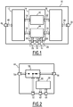
- the figure 2 represents a diagram of the clear mode management device 44 according to one embodiment of the invention.
- the clear mode management device 44 comprises a routing device 50, such as for example a bidirectional switch with one input and two outputs. This switch is suitable for connecting the external physical interface 28 via a port 52, either to the red module 12 through an internal upstream port 54, or to the black module 20 through an internal downstream port 56, exclusively. .
- a routing device 50 such as for example a bidirectional switch with one input and two outputs. This switch is suitable for connecting the external physical interface 28 via a port 52, either to the red module 12 through an internal upstream port 54, or to the black module 20 through an internal downstream port 56, exclusively. .
- the clear mode management device 44 further comprises a control means 58 for the routing device 50, connected to the device 50 through a control link 60 and intended to control the device 50.
- the control means 58 is also connected, on the one hand, to the indicator 32 through an interface port 62 and, on the other hand, to the selector 35 through an interface port 64.
- the red module 12 also called the red domain, contains all the functions and interfaces which process the data in the unencrypted state, that is to say in the clear.
- the functions of the red module 12 perform processing on the unencrypted data before their transfer to the cryptographic functions of the cryptographic module 14.
- the red module 12 comprises a filtering / routing device 66 connected, with a on the one hand, to the interface link 48 and, on the other hand, to the internal upstream link 16.
- the filtering / routing device 66 is also indirectly connected to the internal upstream link 18 through an adapter 68, a sound coding 70 and an analog-to-digital converter 72, successively connected in series.
- the black module 20 also called the black domain, contains all the functions and interfaces which process the data in the encrypted state when it comes from the cryptographic block 42, and in the clear state when it comes from the mode management device. light 44 without passing through the red module 12.
- the functions of the black module 20 perform processing on the data before their transmission to the output interface 38.
- the black module 20 comprises two independent information processing chains between, on the one hand, the downstream internal link 22 and a first internal connection to a radiofrequency adapter 74 and, on the other hand, the downstream internal link 24 and a second internal connection of the radiofrequency adapter 74. Furthermore, the radiofrequency adapter 74 is also connected through a third connection to the interface link 40.
- the first information processing chain intended for processing sensitive information, comprises a digital-to-analog converter 76 connected at the input to the downstream internal link 22 and, at the output, to the input of a modulator / demodulator 78. This the latter is also connected at the output to the first internal connection of the Radiofrequency adapter 74.
- the second information processing chain intended for processing non-sensitive information, comprises an analog-to-digital converter 80, identical to the analog-to-digital converter 72, a sound coding device 82, identical to the sound coding device 70, a digital-to-analog converter 84 and a modulator-demodulator 86 successively connected in series.
- the analog-to-digital converter 80 is connected at input to the downstream internal link 24, the modulator-demodulator 86 being connected at the output to the second internal connection of the radiofrequency adapter 74.
- the cryptographic equipment 10 comprises two exclusive operating modes allowing a bidirectional exchange of information between the input interface 26 and the output interface 38: a first mode, or “cipher” mode, allowing the processing of sensitive data. in a secure manner, and a second mode, or “clear” mode, allowing the processing of non-sensitive data.
- a first mode or “cipher” mode
- a second mode or “clear” mode
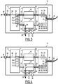
- the figures 3 and 4 illustrate the operation of an example of cryptographic equipment 10, for example a tactical radio station, according to the chosen operating mode.
- the radio station comprises an audio handset connected to the external physical interface 28, thus corresponding to an audio port of the radio station.
- a selection instruction is sent on the link 36 to the control means 58 via the interface port 64, as illustrated on the figure 2 .
- the control means 58 After receiving the selection instruction, the control means 58 sends a control signal over the control link 60 to the routing device 50, in order to create the link corresponding to the chosen operating mode.
- the routing device 50 makes an internal connection 88 or 90 in order to connect the interface port 52, either to the internal port 54 or to the internal port 56.
- the internal connection 88 makes an end-to-end connection 92 visible on the figure 3 .
- the internal connection 90 makes an end-to-end connection 94 visible on the figure 4 .
- control means 58 sends an information signal to the indicator 32 via the interface port 62, in order to supply the indicator 32 as a function of the connection made and therefore of the operating mode. current.
- the user selects the corresponding position on the selection means 35 which then sends a selection instruction on the interface link 36 to the light mode management device 44.
- the light mode management device 44 controls the internal connection 88 between the external physical interface 28 and the red module 12, thus connecting the internal link 18 to the interface link 30.
- a specific information signal is sent by the clear mode management device 44 on the interface link 34 to the indicator 32, in order to trigger its supply in correspondence with the “digit” mode.
- the color red will light up.
- the voice is then converted in the form of a data stream using the analog-digital converter 72.
- This stream is then vocoded by the sound coding device. 70.
- the data then pass through the adapter 68 which performs a conversion of the corresponding signal before the data is transmitted to the filtering / routing device 66.
- the latter then transfers the audio data to the cryptographic block 42 through the link internal upstream 16.
- the digitized and vocoded audio stream is sent to the cryptographic module 14 for encryption. It is then encrypted by the cryptographic functions of the cryptographic block 42 then transmitted over the link 22 to the black module 20, or black domain.
- the data received by the black module 20 are converted into analog form using the digital-to-analog converter 76 of the first information processing chain and then transferred to the associated modulator / demodulator 78 which modulates the corresponding signal.
- the data is then transmitted to the radiofrequency adapter 74 which performs the filtering and signal amplification operations before the data is transmitted over the link 40 to the output interface 38, corresponding for example to an antenna interface.
- the audio data passing from the output interface 38 to the external physical interface 28 follows an identical path to the upstream internal link 16. Then, the audio data is filtered and then routed by the filtering / routing device 66 of the device. red module 12 to the internal upstream link 18 intended for the clear mode management device 44 after having passed through the adapter 68, the sound coding device 70 and the analog-to-digital converter 72 of the module 12 respectively.
- the end-to-end bidirectional connection 92 is established between the external physical interface 28 and the output interface 38, in order to offer a secure voice communication service.
- the sensitive data transmitted on the additional external physical interface 46 through the link 48 are sent directly and only to the filtering / routing device 66 of the red module 12 then transmitted over the internal upstream link 16 to the cryptographic block 42 .
- sensitive data follows an identical path to audio data. Indeed, after encryption, the cryptographic block 42 sends the encrypted data through the downstream internal link 22 to the black module 20.
- the signal in the form of a secure wave, associated with the data is transmitted to the adapter. Radio frequency 74. Then, this signal is transmitted over the interface link 40 to the output interface 38.
- the Radiofrequency signal containing secure data received from the output interface 38, is routed to the downstream internal link 22, thanks to the use of a specific filter for the secure waveform within the Radiofrequency adapter 74, after having been transformed by the demodulator 78 and the digital-to-analog converter 76.
- the data is sent on the internal upstream link 16 to the filtering / routing device 66 of the red module 12 which will make it possible to route the data to the additional external physical interface 46.
- a bidirectional connection 96 is made between the additional external physical interface 46 and the output interface 38, in order to offer a secure data communication service.
- the radio set offers two communication services available in parallel: a secure data communication service, and a secure voice communication service.
- the second mode of operation or "clear" mode of the cryptographic equipment 10 is illustrated on figure 4 .
- a selection instruction is sent to the device for managing the light mode 44.
- the light mode management device 44 On receipt of this instruction, the light mode management device 44 establishes a connection 90, different from connection 88, between the external physical interface 28 and the black module 20, thus connecting the internal link 24 to the interface link 30. After the connection 90 has been established, the light mode management device 44 sends a specific information signal to the indicator 32, such as for example to the indicator light with several colors, thus triggering the lighting of the indicator light by a color corresponding to the “light” mode, for example green.
- the voice data from the audio handset of an analog nature are transmitted on the external physical interface 28 to the management device. 44.
- the information is then routed by the management device 44 to the black module 20 which performs an adaptation of the information received in clear in order to allow their transmission to the external environment via the output interface 38.
- the audio data transmitted on the link 24 are converted within the second information processing chain in the form of a digital signal using the analog-to-digital converter 80
- the sound encoder 82 performs compression of the signal which is then converted back to an analog format in a clear waveform by the digital-to-analog converter 84.
- a modulator / demodulator 86 performs the modulation operation.
- the radiofrequency adapter 74 then adapts the signal into a clean radiofrequency signal to be transmitted to the output interface 38.
- the radiofrequency signal containing unencrypted data received from the antenna interface is routed to link 24 by the black module 20.
- This routing is carried out through the use of a specific filter within the radiofrequency adapter. 74 for distinguishing between a clear waveform signal and a secure waveform signal.
- This signal then undergoes, within the second information processing chain, the various processes of demodulation by the modulator / demodulator 86, of analog-to-digital conversion by the digital-to-analog converter 84, of decompression by the coding device. sound 82 and digital-to-analog conversion by the analog-to-digital converter 80 in order to be transmitted to the clear mode management device 44.
- a specific bidirectional connection 94 different from the bidirectional connection 92, is established between the external physical interface 28 and the output interface 38, making it possible to offer a clear voice communication service.
- the “clear” mode is suitable for also offering a secure data communication service thanks to the establishment of the two-way connection 96 between the additional external physical interface 46 and the output interface 38.
- the radio station offers two communication services available in parallel: a secure data communication service, and a clear voice communication service.
- the cryptographic block 42 and the clear mode management device 44 being physically distinct and autonomous, in the event of failure of the cryptographic block 42, the clear voice communication service remains available since only the management device 44 and the module black 20 are necessary for the establishment of a free audio communication.
- the cryptographic equipment 10 has the advantage of avoiding the unencrypted transmission of sensitive data received on the additional external physical interface 46 through the cryptographic block 42 and not to interrupt the security services offered by the cryptographic equipment 10.
- the activation of the “clear” mode at the level of the management device 44 does not disturb either the execution or the implementation of the operations. cryptographic functions of cryptographic equipment 10.
- the architecture and the particular operation of the cryptographic equipment 10 make it possible to eliminate the need to implement a transmission channel in the clear at the level of the cryptographic block 42.
- cryptographic equipment such as for example a use as a network encryptor, a route encryptor, an encrypting audio handset or an encrypting terminal (encrypting telephone).
- the red module can comprise, for example, one of the following elements: a sound encoding device, a sound reproduction device, an echo cancellation device, an audio gain control device, a detection and correction device errors, an analog-to-digital converter, a digital-to-analog converter, a data packet classification device, a data routing device and a data filtering device.
- the black module may include one of the following elements: sound coding device, a sound reproduction device, an analog-to-digital converter, a modulator / demodulator, a device for detecting and correcting transmission errors, a digital-to-analog converter , an electrical, radio frequency or optical transmitter / receiver, an electrical, radio frequency or optical power amplifier, a data routing device, a data filtering device, and a data packet classification device.
- the output interface can be an audio interface, for example a loudspeaker, a radiofrequency interface, for example an antenna, a wired electrical interface, for example a USB or Ethernet interface, or an optical interface, of the Ethernet type for example. .
- the management device can include at least one of the following elements: an electromechanical component, a discrete electronic component, a programmable logic circuit, and an integrated circuit.
Landscapes
- Engineering & Computer Science (AREA)
- Theoretical Computer Science (AREA)
- Computer Security & Cryptography (AREA)
- Physics & Mathematics (AREA)
- General Physics & Mathematics (AREA)
- Computer Networks & Wireless Communication (AREA)
- Signal Processing (AREA)
- Bioethics (AREA)
- Health & Medical Sciences (AREA)
- General Health & Medical Sciences (AREA)
- Computer Hardware Design (AREA)
- Software Systems (AREA)
- General Engineering & Computer Science (AREA)
- Mobile Radio Communication Systems (AREA)
- Telephonic Communication Services (AREA)
- User Interface Of Digital Computer (AREA)
- Small-Scale Networks (AREA)
- Financial Or Insurance-Related Operations Such As Payment And Settlement (AREA)
Description
- La présente invention concerne un équipement cryptographique comprenant :
- une interface d'entrée, permettant d'interagir avec l'équipement cryptographique et d'échanger des informations sensibles ou non-sensibles de manière séquentielle,
- un module rouge, destiné à traiter des informations sensibles,
- un module cryptographique, relié au module rouge par un premier lien interne amont et propre à appliquer des fonctions cryptographiques,
- un module noir, relié au module cryptographique par un premier lien interne aval et propre à traiter des informations non-sensibles, et
- une interface de sortie, reliée au module noir par un premier lien d'interface et destinée à gérer l'échange d'informations depuis l'équipement cryptographique.
- Elle se situe dans le domaine de la sécurité des systèmes d'informations.
- Elle concerne la conception d'équipements de sécurité et, plus particulièrement, la conception des équipements cryptographiques, comme les postes de radio tactique, traitant d'informations sensibles.
- Les équipements cryptographiques ont une architecture comprenant généralement un domaine hôte rouge et un domaine hôte noir séparés physiquement par un domaine cryptographique. Le domaine hôte rouge traite des informations sensibles en clair. Le domaine hôte noir traite des informations non-sensibles, dont la divulgation n'entraîne pas de compromission de la sécurité du système d'information. Ces informations non-sensibles sont soit des informations en clair, intrinsèquement non-sensibles, soit des informations chiffrées, intrinsèquement sensibles mais désensibilisées par chiffrement.
- Le domaine cryptographique comporte un bloc cryptographique doté de fonctions cryptographiques nécessaires à une protection/dé-protection des informations sensibles se plaçant en coupure des domaines hôtes rouge et noir. Les équipements cryptographiques comprennent également deux interfaces externes : une première interface ou interface utilisateur, reliée au domaine hôte rouge, et une seconde interface ou interface externe, reliée au domaine hôte noir.
- L'équipement cryptographique comprend un mode « chiffre » propre au traitement des informations sensibles. Dans le mode « chiffre » :
- les informations sensibles, entrant sur l'interface utilisateur, sont chiffrées par le domaine cryptographique et sortent sécurisées sur l'interface externe du domaine noir.
- les informations entrant sur l'interface externe sont déchiffrées par le domaine cryptographique et sortent, à l'état clair, sur l'interface utilisateur du domaine rouge.
- En plus du mode « chiffre », certains équipements cryptographiques possèdent un mode « clair » qui permet de traiter des informations non sensibles.
- Ainsi, le mode «chiffre» permet de sécuriser les informations sensibles en faisant appel aux fonctions cryptographiques du domaine cryptographique, le mode «clair» ne faisant pas appel aux fonctions cryptographiques pour la transmission des informations.
- Les implémentations connues s'appuient sur la mise en place au sein des équipements cryptographiques d'un canal de transmission en clair entre le domaine hôte rouge et le domaine hôte noir permettant de ne pas appliquer de protection cryptographique et permettant l'échange d'informations en clair entre les deux domaines. Plus précisément, le canal de transmission en clair relie directement le domaine hôte rouge et le domaine hôte noir en traversant le bloc cryptographique du domaine cryptographique sans passer par les fonctions cryptographiques du bloc cryptographique.
- Or, la mise en oeuvre du mode «clair» au sein d'un équipement cryptographique engendre un risque de sécurité majeur pour la confidentialité des informations sensibles de l'utilisateur.
- En effet, l'activation intempestive du mode «clair», par exemple par une action involontaire de l'utilisateur ou une défaillance de l'équipement cryptographique, est propre à entraîner une divulgation des informations sensibles de l'utilisateur, comme une transmission en clair d'informations sensibles, et/ou une indisponibilité des applications sensibles de l'utilisateur, correspondant à une interruption de services de sécurité offerts par l'équipement.
- D'autre part, ce type d'équipement est utilisé dans les domaines aéronautiques et tactiques qui nécessitent une disponibilité importante du mode «clair» qui correspond généralement à une fonction de secours de l'équipement cryptographique.
- Les documents
US 5 995 628 etFR 2 901 939 - Le but de l'invention est donc de proposer une nouvelle architecture de l'équipement cryptographique, permettant la mise en oeuvre du mode «clair» en toute circonstance, sans remettre en cause la sécurité globale de l'équipement et sans affecter la disponibilité de l'équipement et des applications associées.
- A cet effet, l'invention a pour objet un équipement cryptographique du type précité, caractérisé en ce que le module cryptographique comporte :
- un bloc cryptographique interagissant d'une part avec le module rouge au travers du premier lien interne amont, et d'autre part avec le module noir au travers du premier lien interne aval et propre à traiter les informations sensibles à l'aide des fonctions cryptographiques, et
- un dispositif de gestion, interagissant avec l'interface d'entrée au travers d'au moins un second lien d'interface et avec soit le module rouge au travers d'un second lien interne amont, soit le module noir au travers d'un second lien interne aval à l'exclusion des deux simultanément, et propre à aiguiller les informations sensibles entre l'interface d'entrée et le second lien interne amont, ou les informations non-sensibles entre l'interface d'entrée et le second lien interne aval, sans que les informations non-sensibles ne transitent par le module rouge,
- Suivant d'autres modes de réalisation, l'équipement cryptographique comprend une ou plusieurs des caractéristiques suivantes, prises isolément ou suivant toutes les combinaisons techniquement possibles :
- le bloc cryptographique et le dispositif de gestion ont des ressources matérielles propres ;
- le dispositif de gestion comprend :
- un dispositif d'aiguillage connecté à la fois au second lien interne amont, au second lien interne aval et à au moins un second lien d'interface, le dispositif d'aiguillage étant destiné à relier l'interface d'entrée soit au module rouge, soit au module noir, à l'exclusion des deux simultanément, et
- un moyen de contrôle du dispositif d'aiguillage connecté à la fois :
- au dispositif d'aiguillage afin de commander la liaison à réaliser, et
- à l'interface d'entrée, afin d'une part de recevoir une consigne de sélection de la liaison à réaliser suivant un mode de fonctionnement choisi et, d'autre part, d'informer l'utilisateur du mode de fonctionnement courant ;
- l'interface d'entrée comprend:
- une interface physique externe reliée au dispositif d'aiguillage et destinée à transmettre les informations sensibles ou non-sensibles vers l'équipement cryptographique et à recevoir les informations sensibles ou non-sensibles de l'équipement cryptographique,
- un indicateur relié au moyen de contrôle du dispositif d'aiguillage et destiné à indiquer le mode de fonctionnement courant, et
- un moyen de sélection relié au moyen de contrôle du dispositif d'aiguillage et destiné à fournir la consigne de sélection du mode de fonctionnement choisi ;
- l'équipement cryptographique comprend une interface physique externe supplémentaire reliée au module rouge et destinée à transmettre et à recevoir des informations sensibles, sans transit par le dispositif de gestion ;
- le module rouge comporte un élément du groupe consistant en : un dispositif de codage sonore, un dispositif de restitution sonore, un dispositif d'annulation d'écho, un dispositif de contrôle de gain audio, un dispositif de détection et de correction d'erreurs, un convertisseur analogique-numérique, un convertisseur numérique-analogique, un dispositif de classification de paquets de données, un dispositif de routage de données, et un dispositif de filtrage de données ;
- le module noir comporte un élément du groupe consistant en : un dispositif de codage sonore, un dispositif de restitution sonore, un convertisseur analogique-numérique, un modulateur/démodulateur, un dispositif de détection et de correction d'erreurs de transmission, un convertisseur numérique-analogique, un émetteur/récepteur électrique, radiofréquence ou optique, un amplificateur de puissance électrique, radiofréquence ou optique, un dispositif de routage de données, un dispositif de filtrage de données, et un dispositif de classification de paquets de données ;
- l'interface de sortie est un élément du groupe consistant en : une interface audio, une interface radiofréquence, une interface électrique filaire, et une interface optique ;
- l'équipement cryptographique est un élément du groupe consistant en : un poste de radio, un chiffreur réseau, un chiffreur d'artère, un combiné audio chiffrant, et un terminal chiffrant ;
- le dispositif de gestion comporte au moins un des éléments du groupe consistant en : un composant électromécanique, un composant électronique discret, un circuit logique programmable, et un circuit intégré.
- La présente invention concerne aussi un équipement cryptographique selon la revendication 1.
- Suivant d'autres modes de réalisation, l'équipement cryptographique comprend une ou plusieurs des caractéristiques des revendications 2 à 10, prises isolément ou suivant toutes les combinaisons techniquement possibles.
- L'invention sera mieux comprise à la lecture de la description qui va suivre, donnée uniquement à titre d'exemple et faite en se référant aux dessins annexés, sur lesquels :
- la
figure 1 est une représentation schématique d'un équipement cryptographique selon l'invention, - la
figure 2 est une représentation schématique d'un dispositif de gestion du mode clair selon l'invention, - la
figure 3 est une représentation schématique d'un poste de radio tactique suivant un premier mode de fonctionnement selon l'invention, et - la
figure 4 est une représentation schématique d'un poste de radio tactique suivant un second mode de fonctionnement selon l'invention. - L'équipement cryptographique 10 selon l'invention, illustré sur la
figure 1 , constitue dans l'exemple considéré un poste de radio tactique propre à émettre et recevoir suivant deux modes de fonctionnement, à savoir un mode «chiffre» et un mode «clair» suivant que les informations transmises soient protégées ou non en confidentialité. Cet équipement se caractérise par une architecture de sécurité divisée en trois modules. Un module rouge 12, appelé également domaine hôte rouge, est relié à un module cryptographique 14, appelé également domaine cryptographique, au travers de deux liens amont 16, 18. Un module noir 20, appelé également domaine hôte noir, est connecté au module cryptographique 14 par l'intermédiaire de deux liens internes avales 22, 24. - Le module rouge 12 est propre à traiter des informations sensibles en clair.
- Le module noir 20 est propre à traiter seulement des informations non-sensibles, c'est-à-dire sans compromission de sécurité en cas de divulgation. Ces informations sont soit des informations en clair, intrinsèquement non-sensibles, soit des informations chiffrées, intrinsèquement sensibles mais rendues non-sensibles par chiffrement.
- Le module cryptographique 14 est propre à assurer la désensibilisation, respectivement la sensibilisation, des informations transitant du module rouge vers le module noir, respectivement du module noir vers le module rouge. A cet effet, il met en oeuvre des algorithmes et des clés cryptographiques pour chiffrer et déchiffrer ces informations.
- L'équipement cryptographique 10 comprend une interface d'entrée 26, bidirectionnelle, reliée au module cryptographique 14.
- Par exemple, comme illustré sur la
figure 1 , l'interface d'entrée 26 comporte une interface physique externe 28 reliée au module cryptographique 14 par un lien d'interface 30. L'interface externe 28 est destinée à transmettre des informations vers l'équipement cryptographique 10 et à recevoir des informations de l'équipement cryptographique 10. - L'interface 26 comprend également un indicateur 32 sonore ou visuel, comme par exemple un témoin lumineux à plusieurs couleurs, destiné à indiquer le mode de fonctionnement courant et relié au module cryptographique 14 au travers d'un lien d'interface 34. Elle comprend enfin un moyen de sélection 35 propre à choisir le mode de fonctionnement souhaité, c'est-à-dire soit le mode « clair », soit le mode « chiffre ». Ce dernier est connecté au module cryptographique 14 par l'intermédiaire d'un lien d'interface 36.
- En outre, l'équipement cryptographique 10 comprend une interface de sortie 38, bidirectionnelle, reliée au module noir 20 au travers d'un lien d'interface 40. Cette interface est destinée à l'échange d'informations non-sensibles entre l'équipement cryptographique 10 et l'environnement extérieur, par exemple un réseau.
- Le module cryptographique 14 comporte deux dispositifs autonomes et distincts, physiquement et logiquement :
- un bloc cryptographique 42 destiné à traiter les informations sensibles à l'aide de fonctions cryptographiques, et
- un dispositif de gestion du mode clair 44, propre à aiguiller les informations dans les deux sens entre l'interface d'entrée 26 et l'un des deux modules noir ou rouge 12, 20 suivant le mode de fonctionnement choisi.
- Plus précisément, le bloc cryptographique 42 est propre à interagir, d'une part, avec le module rouge 12 au travers du lien interne amont 16 et, d'autre part, avec le module noir 20 au travers du lien interne aval 22.
- De la même manière, le dispositif de gestion du mode clair 44 est propre à interagir, d'une part, avec le module rouge 12 au travers du lien interne amont 18 et, d'autre part, avec le module noir 20 au travers du lien interne aval 24.
- En outre, le dispositif de gestion du mode clair 44 est propre à interagir avec l'interface d'entrée 26 au travers d'au moins un lien d'interface, par exemple au travers des liens d'interface 30, 34 et 36.
- Le bloc 42 et le dispositif 44 disposent de ressources matérielles propres, distinctes l'une de l'autre. Par exemple, ils disposent d'une alimentation électrique spécifique qui leur est entièrement dédiée, ainsi que des circuits de traitement propres.
- L'équipement cryptographique 10 répond à des normes et des recommandations de sécurité.
- En particulier, les recommandations de sécurité en vigueur sur l'architecture des équipements cryptographiques préconisent un cloisonnement des fonctions cryptographiques du module cryptographique 14 dans le but d'obtenir un bloc cryptographique 42 autonome ainsi qu'une séparation entre le module rouge 12 et le module noir 20.
- Afin d'obtenir un agrément qui autorise le déploiement de l'équipement cryptographique 10 dans une infrastructure cliente, une évaluation de sécurité est menée pour vérifier la conformité de l'équipement cryptographique 10 par rapport aux recommandations de sécurité susmentionnées.
- Ainsi, pour répondre aux exigences des recommandations, le module cryptographique 14 implémente des mécanismes de protection physique communs au bloc 42 et au dispositif 44, caractérisés par un niveau de protection donné, permettant de protéger en intégrité le bloc cryptographique 42 et le dispositif de gestion 44.
- Par exemple, le module 14 comporte un boîtier constitué d'un châssis et d'un capot. Une étiquette holographique est utilisée pour sceller le châssis et le capot. Ainsi, toute tentative d'accès aux composants internes du module 14 est détectée.
- Les modules rouge 12 et noir 20 disposent également d'un niveau de protection physique donné, celui-ci étant inférieur au niveau de protection du module cryptographique 14.
- Selon un mode de réalisation préféré, l'équipement cryptographique 10 comporte une interface physique externe supplémentaire 46 reliée au module rouge 12 au travers d'un lien d'interface 48. Cette interface 46 véhicule des informations sensibles entre l'équipement cryptographique 10 et l'environnement extérieur, comme par exemple un réseau.
- La
figure 2 représente un schéma du dispositif de gestion du mode clair 44 selon un mode de réalisation de l'invention. - Le dispositif de gestion du mode clair 44 comporte un dispositif d'aiguillage 50, comme par exemple un commutateur bidirectionnel à une entrée et deux sorties. Ce commutateur est propre à relier l'interface physique externe 28 via un port 52, soit au module rouge 12 au travers d'un port interne amont 54, soit au module noir 20 au travers d'un port interne aval 56, de manière exclusive.
- Le dispositif de gestion du mode clair 44 comprend, en outre, un moyen de contrôle 58 du dispositif d'aiguillage 50, relié au dispositif 50 au travers d'un lien de commande 60 et destiné à commander le dispositif 50.
- Le moyen de contrôle 58 est également relié, d'une part, à l'indicateur 32 au travers d'un port d'interface 62 et, d'autre part, au sélecteur 35 au travers d'un port d'interface 64.
- Le module rouge 12, également appelé domaine rouge, contient toutes les fonctions et interfaces qui traitent les données à l'état non chiffré, c'est-à-dire en clair. Les fonctions du module rouge 12 effectuent des traitements sur les données non chiffrées avant leur transfert vers les fonctions cryptographiques du module cryptographique 14.
- Plus précisément, en prenant l'exemple d'un poste radio, comme illustré sur la
figure 3 , le module rouge 12 comporte un dispositif de filtrage/routage 66 connecté, d'une part, au lien d'interface 48 et, d'autre part, au lien interne amont 16. Le dispositif de filtrage/routage 66 est également relié indirectement au lien interne amont 18 au travers d'un adaptateur 68, d'un dispositif de codage sonore 70 et d'un convertisseur analogique-numérique 72, reliés successivement en série. - Le module noir 20, également appelé domaine noir, contient toutes les fonctions et interfaces qui traitent les données à l'état chiffré lorsqu'elles proviennent du bloc cryptographique 42, et à l'état clair lorsqu'elles proviennent du dispositif de gestion du mode clair 44 sans transiter par le module rouge 12. Les fonctions du module noir 20 effectuent des traitements sur les données avant leur transmission vers l'interface de sortie 38.
- Plus précisément, le module noir 20 comprend deux chaînes indépendantes de traitement de l'information entre, d'une part, le lien interne aval 22 et une première connexion interne à un adaptateur Radiofréquence 74 et, d'autre part, le lien interne aval 24 et une seconde connexion interne de l'adaptateur Radiofréquence 74. Par ailleurs, l'adaptateur Radiofréquence 74 est également relié au travers d'une troisième connexion au lien d'interface 40.
- La première chaîne de traitement de l'information, destinée au traitement des informations sensibles, comprend un convertisseur numérique-analogique 76 connecté en entrée au lien interne aval 22 et, en sortie, à l'entrée d'un modulateur/démodulateur 78. Ce dernier est également relié en sortie à la première connexion interne de l'adaptateur Radiofréquence 74.
- La seconde chaîne de traitement de l'information, destinée au traitement des informations non-sensibles, comprend un convertisseur analogique-numérique 80, identique au convertisseur analogique-numérique 72, un dispositif de codage sonore 82, identique au dispositif de codage sonore 70, un convertisseur numérique-analogique 84 et un modulateur-démodulateur 86 reliés successivement en série. De plus, le convertisseur analogique-numérique 80 est connecté en entrée au lien interne aval 24, le modulateur-démodulateur 86 étant relié en sortie à la seconde connexion interne de l'adaptateur Radiofréquence 74.
- Le fonctionnement de l'équipement cryptographique 10, tel que représenté sur la
figure 1 , va être à présent décrit. - L'équipement cryptographique 10 comprend deux modes de fonctionnement exclusifs permettant un échange d'informations bidirectionnel entre l'interface d'entrée 26 et l'interface de sortie 38 : un premier mode, ou mode «chiffre», permettant le traitement des données sensibles de manière sécurisée, et un second mode, ou mode «clair», permettant le traitement des données non sensibles.
- Les
figures 3 et 4 illustrent le fonctionnement d'un exemple d'équipement cryptographique 10, par exemple un poste de radio tactique, suivant le mode de fonctionnement choisi. Dans cet exemple, le poste radio comprend un combiné audio raccordé à l'interface physique externe 28, correspondant ainsi à un port audio du poste radio. - Lorsque l'utilisateur sélectionne un mode de fonctionnement « clair » ou « chiffre » grâce au moyen de sélection 35, une consigne de sélection est envoyée sur le lien 36 vers le moyen de contrôle 58 via le port d'interface 64, comme illustré sur la
figure 2 . Après réception de la consigne de sélection, le moyen de contrôle 58 envoie un signal de commande sur le lien de commande 60 vers le dispositif d'aiguillage 50, afin de réaliser la liaison correspondant au mode de fonctionnement choisi. - Plus précisément, suivant le signal de commande reçu, le dispositif d'aiguillage 50 réalise une connexion interne 88 ou 90 afin de relier le port d'interface 52, soit au port interne 54, soit au port interne 56.
- Dans le premier cas, la connexion interne 88 réalise à une connexion de bout en bout 92 visible sur la
figure 3 . Dans le second cas, la connexion interne 90 réalise à une connexion de bout en bout 94 visible sur lafigure 4 . - Une fois la connexion établie, le moyen de contrôle 58 envoie un signal d'information vers l'indicateur 32 via le port d'interface 62, afin d'alimenter l'indicateur 32 en fonction de la connexion réalisée et donc du mode de fonctionnement courant.
- Ainsi, pour choisir le mode « chiffre », illustré sur la
figure 3 , l'utilisateur sélectionne la position correspondante sur le moyen de sélection 35 qui envoie alors une consigne de sélection sur le lien d'interface 36 à destination du dispositif de gestion du mode clair 44. - Sur réception de cette consigne, le dispositif de gestion du mode clair 44 commande la connexion interne 88 entre l'interface physique externe 28 et le module rouge 12, reliant ainsi le lien interne 18 au lien d'interface 30. Une fois la connexion 88 établie, un signal d'information spécifique est envoyé par le dispositif de gestion du mode clair 44 sur le lien d'interface 34 vers l'indicateur 32, afin de déclencher son alimentation en correspondance avec le mode «chiffre». A titre d'exemple, en utilisant un voyant lumineux à plusieurs couleurs, la couleur rouge s'allume.
- Dès lors, toutes les données sensibles transmises sur l'interface physique externe 28 sont redirigées exclusivement vers le module rouge 12.
- Par exemple, dans le cas d'une communication sécurisée de phonie, la voix est alors convertie sous la forme d'un flux de données à l'aide du convertisseur analogique-numérique 72. Ce flux est ensuite vocodé par le dispositif de codage sonore 70. Les données transitent ensuite par l'adaptateur 68 qui effectue une conversion du signal correspondant avant que les données ne soient transmises vers le dispositif de filtrage/routage 66. Celui-ci réalise alors le transfert des données audio vers le bloc cryptographique 42 au travers du lien interne amont 16.
- Le flux audio numérisé et vocodé est envoyé vers le module cryptographique 14 pour chiffrement. Il est alors chiffré par les fonctions cryptographiques du bloc cryptographique 42 puis transmis sur le lien 22 vers le module noir 20, ou domaine noir.
- Les données reçues par le module noir 20 sont converties sous forme analogique à l'aide du convertisseur numérique-analogique 76 de la première chaîne de traitement de l'information puis transférées vers le modulateur/démodulateur 78 associé qui effectue une modulation du signal correspondant. Les données sont ensuite transmises à l'adaptateur Radiofréquence 74 qui réalise les opérations de filtrage et d'amplification du signal avant que les données ne soient transmises sur le lien 40 vers l'interface de sortie 38, correspondant par exemple à une interface antenne.
- Inversement, les données audio transitant de l'interface de sortie 38 vers l'interface physique externe 28 suivent un cheminement identique jusqu'au lien interne amont 16. Ensuite, les données audio sont filtrées puis aiguillées par le dispositif de filtrage/routage 66 du module rouge 12 vers le lien interne amont 18 à destination du dispositif de gestion du mode clair 44 après avoir traversées respectivement l'adaptateur 68, le dispositif de codage sonore 70 et le convertisseur analogique-numérique 72 du module 12.
- Ainsi, en mode «chiffre», la connexion bidirectionnelle de bout en bout 92 est établie entre l'interface physique externe 28 et l'interface de sortie 38, afin d'offrir un service de communication sécurisé de phonie.
- En outre, les données sensibles transmises sur l'interface physique externe supplémentaire 46 au travers du lien 48 sont envoyées directement et uniquement vers le dispositif de filtrage/routage 66 du module rouge 12 puis transmises sur le lien interne amont 16 vers le bloc cryptographique 42.
- Ensuite, les données sensibles suivent un cheminement identique aux données audio. En effet, après chiffrement, le bloc cryptographique 42 effectue un envoi des données chiffrées au travers du lien interne aval 22 vers le module noir 20.
- Puis, après réalisation au sein du module 20 des opérations de conversion par le convertisseur numérique-analogique 76 et de modulation réalisées par le modulateur/démodulateur 78, le signal sous forme d'onde sécurisée, associé aux données, est transmis vers l'adaptateur Radiofréquence 74. Ensuite, ce signal est transmis sur le lien d'interface 40 vers l'interface de sortie 38.
- En sens inverse, le signal Radiofréquence, contenant des données sécurisées reçues de l'interface de sortie 38, est aiguillé vers le lien interne aval 22, grâce à l'utilisation d'un filtre spécifique pour la forme d'onde sécurisée au sein de l'adaptateur Radiofréquence 74, après avoir été transformé par le démodulateur 78 et le convertisseur numérique-analogique 76.
- Ensuite, à l'issue du traitement cryptographique, les données sont émises sur le lien interne amont 16 vers le dispositif de filtrage/routage 66 du module rouge 12 qui va permettre d'aiguiller les données vers l'interface physique externe supplémentaire 46.
- Dès lors, une connexion bidirectionnelle 96, différente de la connexion 92, est réalisée entre l'interface physique externe supplémentaire 46 et l'interface de sortie 38, afin d'offrir un service de communication sécurisé de données.
- Par conséquent, toutes les informations sensibles transitent obligatoirement par le bloc cryptographique 42 et bénéficient donc d'un traitement cryptographique, comme par exemple des opérations de chiffrement quand les informations transitent du module 12 vers le module 20 et de déchiffrement en sens inverse, assurant ainsi la sécurisation des informations.
- Ainsi, en mode «chiffre», le poste radio offre deux services de communication disponibles en parallèle : un service de communication sécurisé de données, et un service de communication sécurisé de phonie.
- Le second mode de fonctionnement ou mode «clair» de l'équipement cryptographique 10 est illustré sur la
figure 4 . - Suivant le même principe que décrit précédemment, dès que la sélection du mode «clair» est choisie par l'utilisateur sur le moyen de sélection 35, une consigne de sélection est envoyée au dispositif de gestion du mode clair 44.
- Sur réception de cette consigne, le dispositif de gestion du mode clair 44 établit une connexion 90, différente de la connexion 88, entre l'interface physique externe 28 et le module noir 20, reliant ainsi le lien interne 24 au lien d'interface 30. Après l'établissement de la connexion 90, le dispositif de gestion du mode clair 44 envoie un signal d'information spécifique vers l'indicateur 32, comme par exemple vers le voyant lumineux à plusieurs couleurs, déclenchant ainsi l'allumage du voyant en une couleur correspondant au mode «clair», par exemple le vert.
- Dès lors, toutes les informations non sensibles transmises sur l'interface physique externe 28 sont aiguillées uniquement vers le module noir 20, sans transiter par le module rouge 12, puis transmises directement vers l'interface de sortie 38.
- Il en va de même en sens inverse de l'interface de sortie 38 vers l'interface physique externe 28.
- De manière plus précise, en prenant l'exemple du poste radio comprenant un combiné audio raccordé à l'interface physique externe 28, les données vocales issues du combiné audio de nature analogique sont transmises sur l'interface physique externe 28 vers le dispositif de gestion 44.
- Les informations sont ensuite aiguillées par le dispositif de gestion 44 vers le module noir 20 qui effectue une adaptation des informations reçues en clair afin de permettre leur transmission vers l'environnement extérieur via l'interface de sortie 38.
- Plus précisément, au sein du module noir 20, les données audio transmises sur le lien 24 sont converties au sein de la seconde chaîne de traitement de l'information sous la forme d'un signal numérique à l'aide du convertisseur analogique-numérique 80. Puis, le dispositif de codage sonore 82 effectue une compression du signal qui est ensuite reconverti en un format analogique sous une forme d'onde claire par le convertisseur numérique-analogique 84. Ensuite, un modulateur/démodulateur 86 effectue l'opération de modulation puis l'adaptateur Radiofréquence 74 adapte alors le signal en un signal Radiofréquence propre à être transmis à l'interface de sortie 38.
- Inversement, le signal Radiofréquence contenant des données non chiffrées reçues de l'interface antenne est aiguillé vers le lien 24 par le module noir 20. Cet aiguillage s'effectue grâce à l'utilisation d'un filtre spécifique au sein de l'adaptateur Radiofréquence 74 permettant de faire la distinction entre un signal de forme d'onde clair et un signal de forme d'onde sécurisé.
- Ce signal subit ensuite, au sein de la seconde chaîne de traitement de l'information, les différents traitements de démodulation par le modulateur/démodulateur 86, de conversion analogique-numérique par le convertisseur numérique-analogique 84, de décompression par le dispositif de codage sonore 82 et de conversion numérique-analogique par le convertisseur analogique-numérique 80 afin d'être transmis au dispositif de gestion du mode clair 44.
- Ainsi, en mode «clair», une connexion bidirectionnelle spécifique 94, différente de la connexion bidirectionnelle 92, est établie entre l'interface physique externe 28 et l'interface de sortie 38, permettant d'offrir un service de communication de phonie claire.
- De plus, le mode «clair» est propre à offrir également un service de communication sécurisé de données grâce à l'établissement de la connexion bidirectionnelle 96 entre l'interface physique externe supplémentaire 46 et l'interface de sortie 38.
- Ainsi, le cheminement des informations non sensibles en mode «clair» est différent du cheminement des informations sensibles en mode «chiffre», les informations non sensibles ne transitant pas par le bloc cryptographique 42.
- Par conséquent, en mode «clair», le poste radio offre deux services de communication disponibles en parallèle : un service de communication sécurisé de données, et un service de communication de phonie claire.
- Dès lors, le bloc cryptographique 42 et le dispositif de gestion du mode clair 44 étant physiquement distincts et autonomes, en cas de panne du bloc cryptographique 42, le service de communication clair de phonie demeure disponible puisque seuls le dispositif de gestion 44 et le module noir 20 sont nécessaires pour l'établissement d'une communication audio en clair.
- De plus, en cas d'activation involontaire du mode «clair», l'équipement cryptographique 10 présente l'avantage d'éviter la transmission en clair de données sensibles reçues sur l'interface physique externe supplémentaire 46 au travers du bloc cryptographique 42 et de ne pas interrompre les services de sécurité offerts par l'équipement cryptographique 10.
- Ainsi, compte tenu de l'indépendance fonctionnelle et physique du dispositif de gestion 44 par rapport au bloc cryptographique 42, l'activation du mode «clair» au niveau du dispositif de gestion 44 ne perturbe ni l'exécution ni la mise en oeuvre des fonctions cryptographiques de l'équipement cryptographique 10.
- D'autre part, l'architecture et le fonctionnement particulier de l'équipement cryptographique 10 permettent de supprimer le besoin d'implémenter un canal de transmission en clair au niveau du bloc cryptographique 42.
- Par conséquent, lors de l'activation du mode «clair», les opérations habituellement effectuées au niveau du bloc cryptographique 42, comme par exemple l'effacement sécurisé des informations sensibles ou la sauvegarde du contexte d'exécution des fonctions cryptographiques, ne sont plus nécessaires.
- Ainsi, le passage en mode «clair» de l'équipement cryptographique 10 selon l'invention est quasiment instantané.
- D'autres applications peuvent être envisagées pour l'équipement cryptographique, comme par exemple une utilisation en tant que chiffreur réseau, chiffreur d'artère, combiné audio chiffrant ou terminal chiffrant (téléphone chiffrant).
- Bien entendu, d'autres modes de réalisation peuvent être envisagés en fonction des applications de l'équipement cryptographique.
- Le module rouge peut comporter, par exemple, un des éléments suivants : un dispositif de codage sonore, un dispositif de restitution sonore, un dispositif d'annulation d'écho, un dispositif de contrôle de gain audio, un dispositif de détection et de correction d'erreurs, un convertisseur analogique-numérique, un convertisseur numérique-analogique, un dispositif de classification de paquets de données, un dispositif de routage de données et un dispositif de filtrage de données.
- Le module noir peut comporter un des éléments suivants : dispositif de codage sonore, un dispositif de restitution sonore, un convertisseur analogique-numérique, un modulateur/démodulateur, un dispositif de détection et de correction d'erreurs de transmission, un convertisseur numérique-analogique, un émetteur/récepteur électrique, radiofréquence ou optique, un amplificateur de puissance électrique, radiofréquence ou optique, un dispositif de routage de données, un dispositif de filtrage de données, et un dispositif de classification de paquets de données.
- L'interface de sortie peut être une interface audio, par exemple un haut-parleur, une interface radiofréquence, par exemple une antenne, une interface électrique filaire, par exemple une interface USB ou Ethernet, ou une interface optique, de type Ethernet par exemple.
- Enfin, le dispositif de gestion peut comporter au moins un des éléments suivants : un composant électromécanique, un composant électronique discret, un circuit logique programmable, et un circuit intégré.
Claims (10)
- Equipement cryptographique (10) comprenant :- une interface d'entrée (26), permettant d'interagir avec l'équipement cryptographique (10) et d'échanger des informations sensibles ou non-sensibles de manière séquentielle,- un module rouge (12), destiné à traiter des informations sensibles,- un module cryptographique (14), relié au module rouge (12) par un premier lien interne amont (16) et propre à appliquer des fonctions cryptographiques,- un module noir (20), relié au module cryptographique (14) par un premier lien interne aval (22) et propre à traiter des informations non-sensibles, et- une interface de sortie (38), reliée au module noir (20) par un premier lien d'interface (40) et destinée à gérer l'échange d'informations depuis l'équipement cryptographique (10),le module cryptographique (14) comportant :- un bloc cryptographique (42) interagissant d'une part avec le module rouge (12) au travers du premier lien interne amont (16), et d'autre part avec le module noir (20) au travers du premier lien interne aval (22) et propre à traiter les informations sensibles à l'aide des fonctions cryptographiques, et- un dispositif de gestion (44), interagissant avec l'interface d'entrée (26) au travers d'au moins un second lien d'interface (30, 34, 36) et avec soit le module rouge (12) au travers d'un second lien interne amont (18), soit le module noir (20) au travers d'un second lien interne aval (24) à l'exclusion des deux simultanément, et propre à aiguiller les informations sensibles entre l'interface d'entrée (26) et le second lien interne amont (18), ou les informations non-sensibles entre l'interface d'entrée (26) et le second lien interne aval (24), sans que les informations non-sensibles ne transitent par le module rouge (12),le bloc cryptographique (42) et le dispositif de gestion (44) étant physiquement et logiquement distincts l'un de l'autre et autonomes, le bloc cryptographique (42) et le dispositif de gestion (44) disposant de moyen de protection identiques, propres à protéger en intégrité le dispositif de gestion (44) afin de détecter toute tentative d'altération, et caractérisé en ce que l'équipement cryptographique (10) comprend une interface physique externe supplémentaire (46) reliée au module rouge (12) au travers d'un lien d'interface (48), l'interface d'entrée (26) étant propre à établir une première connexion bidirectionnelle sécurisée (92) pour l'échange d'informations avec l'interface de sortie (38), l'interface physique externe supplémentaire (46) étant propre à établir une deuxième connexion bidirectionnelle sécurisée (96) pour l'échange d'informations avec l'interface de sortie (38), la première et la deuxième connexion bidirectionnelle étant différentes et disponibles en parallèle.
- Equipement cryptographique (10) selon la revendication 1, caractérisé en ce que le bloc cryptographique (42) et le dispositif de gestion (44) ont des ressources matérielles propres.
- Equipement cryptographique (10) selon la revendication 1 ou 2, caractérisé en ce que le dispositif de gestion (44) comprend :- un dispositif d'aiguillage (50) connecté à la fois au second lien interne amont (18), au second lien interne aval (24) et à au moins un second lien d'interface (30, 34, 36), le dispositif d'aiguillage (50) étant destiné à relier l'interface d'entrée (26) soit au module rouge (12), soit au module noir (20), à l'exclusion des deux simultanément, et- un moyen de contrôle (58) du dispositif d'aiguillage connecté à la fois :- au dispositif d'aiguillage (50) afin de commander la liaison à réaliser, et- à l'interface d'entrée (26), afin d'une part de recevoir une consigne de sélection de la liaison à réaliser suivant un mode de fonctionnement choisi et, d'autre part, d'informer l'utilisateur du mode de fonctionnement courant.
- Equipement cryptographique (10) selon la revendication 3, caractérisé en ce que l'interface d'entrée (26) comprend:- une interface physique externe (28) reliée au dispositif d'aiguillage (50) et destinée à transmettre les informations sensibles ou non-sensibles vers l'équipement cryptographique (10) et à recevoir les informations sensibles ou non-sensibles de l'équipement cryptographique (10),- un indicateur (32) relié au moyen de contrôle (58) du dispositif d'aiguillage et destiné à indiquer le mode de fonctionnement courant, et- un moyen de sélection (35) relié au moyen de contrôle (58) du dispositif d'aiguillage et destiné à fournir la consigne de sélection du mode de fonctionnement choisi.
- Equipement cryptographique (10) selon l'une quelconque des revendications précédentes, caractérisé en ce que l'équipement cryptographique (10) comprend une interface physique externe supplémentaire (46) reliée au module rouge (12) et destinée à transmettre et à recevoir des informations sensibles, sans transit par le dispositif de gestion (44).
- Equipement cryptographique (10) selon l'une quelconque des revendications précédentes, caractérisé en ce que le module rouge (12) comporte un élément du groupe consistant en : un dispositif de codage sonore, un dispositif de restitution sonore, un dispositif d'annulation d'écho, un dispositif de contrôle de gain audio, un dispositif de détection et de correction d'erreurs, un convertisseur analogique-numérique, un convertisseur numérique-analogique, un dispositif de classification de paquets de données, un dispositif de routage de données, et un dispositif de filtrage de données.
- Equipement cryptographique (10) selon l'une quelconque des revendications précédentes, caractérisé en ce que le module noir (20) comporte un élément du groupe consistant en : un dispositif de codage sonore, un dispositif de restitution sonore, un convertisseur analogique-numérique, un modulateur/démodulateur, un dispositif de détection et de correction d'erreurs de transmission, un convertisseur numérique-analogique, un émetteur/récepteur électrique, radiofréquence ou optique, un amplificateur de puissance électrique, radiofréquence ou optique, un dispositif de routage de données, un dispositif de filtrage de données, et un dispositif de classification de paquets de données.
- Equipement cryptographique (10) selon l'une quelconque des revendications précédentes, caractérisé en ce que l'interface de sortie (38) est un élément du groupe consistant en : une interface audio, une interface radiofréquence, une interface électrique filaire, et une interface optique.
- Equipement cryptographique (10) selon l'une quelconque des revendications précédentes, caractérisé en ce que l'équipement cryptographique (10) est un élément du groupe consistant en : un poste de radio, un chiffreur réseau, un chiffreur d'artère, un combiné audio chiffrant, et un terminal chiffrant.
- Equipement cryptographique (10) selon l'une quelconque des revendications précédentes, caractérisé en ce que le dispositif de gestion (44) comporte au moins un des éléments du groupe consistant en : un composant électromécanique, un composant électronique discret, un circuit logique programmable, et un circuit intégré.
Priority Applications (1)
| Application Number | Priority Date | Filing Date | Title |
|---|---|---|---|
| PL12713731T PL2697928T3 (pl) | 2011-04-11 | 2012-04-11 | Sprzęt kryptograficzny realizujący czerwony i czarny tryb komunikacji |
Applications Claiming Priority (2)
| Application Number | Priority Date | Filing Date | Title |
|---|---|---|---|
| FR1101105A FR2973974B1 (fr) | 2011-04-11 | 2011-04-11 | Equipement cryptographique. |
| PCT/EP2012/056571 WO2012140077A1 (fr) | 2011-04-11 | 2012-04-11 | Equipement cryptographique mettat en oeuvre les modes rouges et noir de communication |
Publications (2)
| Publication Number | Publication Date |
|---|---|
| EP2697928A1 EP2697928A1 (fr) | 2014-02-19 |
| EP2697928B1 true EP2697928B1 (fr) | 2021-05-05 |
Family
ID=45952548
Family Applications (1)
| Application Number | Title | Priority Date | Filing Date |
|---|---|---|---|
| EP12713731.3A Active EP2697928B1 (fr) | 2011-04-11 | 2012-04-11 | Equipement cryptographique mettant en oeuvre les modes rouges et noir de communication |
Country Status (8)
| Country | Link |
|---|---|
| US (1) | US9323952B2 (fr) |
| EP (1) | EP2697928B1 (fr) |
| ES (1) | ES2871223T3 (fr) |
| FR (1) | FR2973974B1 (fr) |
| HU (1) | HUE055238T2 (fr) |
| PL (1) | PL2697928T3 (fr) |
| SG (1) | SG194170A1 (fr) |
| WO (1) | WO2012140077A1 (fr) |
Families Citing this family (2)
| Publication number | Priority date | Publication date | Assignee | Title |
|---|---|---|---|---|
| WO2013064717A1 (fr) * | 2011-11-01 | 2013-05-10 | Savox Communications Oy Ab (Ltd) | Equipement de communication pour une communication sécurisée |
| US10891396B2 (en) * | 2016-05-27 | 2021-01-12 | Samsung Electronics Co., Ltd. | Electronic circuit performing encryption/decryption operation to prevent side- channel analysis attack, and electronic device including the same |
Family Cites Families (6)
| Publication number | Priority date | Publication date | Assignee | Title |
|---|---|---|---|---|
| FR2754375B1 (fr) * | 1996-10-07 | 1998-11-20 | Sleever Int | Enveloppe de securite pour objets, notamment pour des recipients a dispositif de fermeture, du type constitue par un manchon en matiere plastique thermoretractable equipe d'un element holographique |
| US5995628A (en) * | 1997-04-07 | 1999-11-30 | Motorola, Inc. | Failsafe security system and method |
| GB0012478D0 (en) * | 2000-05-24 | 2000-07-12 | Ibm | Intrusion detection mechanism for cryptographic cards |
| US7298975B2 (en) * | 2000-07-13 | 2007-11-20 | L-3 Communications Integrated Systems L.P. | Synchronous collapsed ring architecture for real-time signal switching and distribution |
| US7877595B2 (en) * | 2004-03-23 | 2011-01-25 | Harris Corporation | Modular cryptographic device and related methods |
| FR2901939B1 (fr) * | 2006-06-06 | 2012-11-16 | Thales Sa | Architectures de securite ameliorees en deux et trois parties physiquement separees |
-
2011
- 2011-04-11 FR FR1101105A patent/FR2973974B1/fr not_active Expired - Fee Related
-
2012
- 2012-04-11 HU HUE12713731A patent/HUE055238T2/hu unknown
- 2012-04-11 WO PCT/EP2012/056571 patent/WO2012140077A1/fr not_active Ceased
- 2012-04-11 EP EP12713731.3A patent/EP2697928B1/fr active Active
- 2012-04-11 US US14/111,096 patent/US9323952B2/en not_active Expired - Fee Related
- 2012-04-11 PL PL12713731T patent/PL2697928T3/pl unknown
- 2012-04-11 ES ES12713731T patent/ES2871223T3/es active Active
- 2012-04-11 SG SG2013075940A patent/SG194170A1/en unknown
Also Published As
| Publication number | Publication date |
|---|---|
| PL2697928T3 (pl) | 2021-11-08 |
| FR2973974A1 (fr) | 2012-10-12 |
| EP2697928A1 (fr) | 2014-02-19 |
| US20140032931A1 (en) | 2014-01-30 |
| FR2973974B1 (fr) | 2013-09-27 |
| ES2871223T3 (es) | 2021-10-28 |
| US9323952B2 (en) | 2016-04-26 |
| SG194170A1 (en) | 2013-12-30 |
| HUE055238T2 (hu) | 2021-11-29 |
| WO2012140077A1 (fr) | 2012-10-18 |
Similar Documents
| Publication | Publication Date | Title |
|---|---|---|
| EP2215801B1 (fr) | Procede de securisation d'un canal bidirectionnel de communication et dispositif de mise en oeuvre du procede. | |
| EP0721271B1 (fr) | Système de contrôle d'accès à des machines informatiques connectées en réseau privé | |
| EP1792433B1 (fr) | Systeme et procede destines a creer une application de securite pour un module de cryptographie programmable | |
| BR112019020749A2 (pt) | método de transmissão de pacotes de dados de um dispositivo cliente para a nuvem. | |
| US20030061496A1 (en) | Method and apparatus for performing secure communications | |
| TW201701605A (zh) | 安全動態通訊網絡及協定 | |
| Lewis et al. | A Secure Quantum Communications Infrastructure for Europe: Technical background for a policy vision | |
| CN104239808A (zh) | 数据加密传输方法及装置 | |
| WO2012140077A1 (fr) | Equipement cryptographique mettat en oeuvre les modes rouges et noir de communication | |
| EP2192515B1 (fr) | Circuit électronique de sécurisation des échanges de données entre un poste informatique et un réseau | |
| US20170034214A1 (en) | Apparatus and method for cross enclave information control | |
| WO2010046480A1 (fr) | Outil de supervision et/ou d'hypervision centralisee d'un ensemble de systemes de niveaux de securite differents | |
| US20250273914A1 (en) | Plug connector housing having a data diode for electronic data lines | |
| US20240056824A1 (en) | Method in a telecommunication network, and computer system | |
| CN109673013A (zh) | 一种执法记录仪数据传输控制方法 | |
| WO2025029997A2 (fr) | Systèmes, procédés et dispositifs de communication chiffrée | |
| US9781076B2 (en) | Secure communication system | |
| FR3131497A1 (fr) | Dispositif de gestion d’une requête de transfert de données | |
| EP3040873A1 (fr) | Système électronique configurable de transfert de données et procédé de configuration associé | |
| FR2915648A1 (fr) | Procede de securisation d'un flux de donnees | |
| FR2834851A1 (fr) | Module d'interface entre un reseau de communication et des capteurs et/ou actionneurs | |
| FR3003712A1 (fr) | Module de securite materiel | |
| FR2914520A1 (fr) | Encodeur-transmetteur a cle de cryptage symetrique de longueur infinie | |
| WO2007141301A1 (fr) | Procede et dispositif de transmission de donnees en clair a travers une ressource cryptographique sans canal clair | |
| FR2996087A1 (fr) | Procede de securisation d'un canal de transmission de donnees de voix et dispostif de securisation associe |
Legal Events
| Date | Code | Title | Description |
|---|---|---|---|
| PUAI | Public reference made under article 153(3) epc to a published international application that has entered the european phase |
Free format text: ORIGINAL CODE: 0009012 |
|
| 17P | Request for examination filed |
Effective date: 20131010 |
|
| AK | Designated contracting states |
Kind code of ref document: A1 Designated state(s): AL AT BE BG CH CY CZ DE DK EE ES FI FR GB GR HR HU IE IS IT LI LT LU LV MC MK MT NL NO PL PT RO RS SE SI SK SM TR |
|
| DAX | Request for extension of the european patent (deleted) | ||
| RIN1 | Information on inventor provided before grant (corrected) |
Inventor name: DUPUTZ, PATRICK Inventor name: BINESSE, DOMINIQUE Inventor name: MAILLARD, ROMARIC Inventor name: MACE, GAEL |
|
| STAA | Information on the status of an ep patent application or granted ep patent |
Free format text: STATUS: EXAMINATION IS IN PROGRESS |
|
| 17Q | First examination report despatched |
Effective date: 20180503 |
|
| GRAP | Despatch of communication of intention to grant a patent |
Free format text: ORIGINAL CODE: EPIDOSNIGR1 |
|
| STAA | Information on the status of an ep patent application or granted ep patent |
Free format text: STATUS: GRANT OF PATENT IS INTENDED |
|
| INTG | Intention to grant announced |
Effective date: 20201113 |
|
| GRAS | Grant fee paid |
Free format text: ORIGINAL CODE: EPIDOSNIGR3 |
|
| GRAA | (expected) grant |
Free format text: ORIGINAL CODE: 0009210 |
|
| STAA | Information on the status of an ep patent application or granted ep patent |
Free format text: STATUS: THE PATENT HAS BEEN GRANTED |
|
| AK | Designated contracting states |
Kind code of ref document: B1 Designated state(s): AL AT BE BG CH CY CZ DE DK EE ES FI FR GB GR HR HU IE IS IT LI LT LU LV MC MK MT NL NO PL PT RO RS SE SI SK SM TR |
|
| REG | Reference to a national code |
Ref country code: GB Ref legal event code: FG4D Free format text: NOT ENGLISH |
|
| REG | Reference to a national code |
Ref country code: CH Ref legal event code: EP |
|
| REG | Reference to a national code |
Ref country code: AT Ref legal event code: REF Ref document number: 1391192 Country of ref document: AT Kind code of ref document: T Effective date: 20210515 |
|
| REG | Reference to a national code |
Ref country code: DE Ref legal event code: R096 Ref document number: 602012075466 Country of ref document: DE |
|
| REG | Reference to a national code |
Ref country code: IE Ref legal event code: FG4D Free format text: LANGUAGE OF EP DOCUMENT: FRENCH |
|
| REG | Reference to a national code |
Ref country code: NL Ref legal event code: FP |
|
| REG | Reference to a national code |
Ref country code: LT Ref legal event code: MG9D |
|
| REG | Reference to a national code |
Ref country code: AT Ref legal event code: MK05 Ref document number: 1391192 Country of ref document: AT Kind code of ref document: T Effective date: 20210505 |
|
| REG | Reference to a national code |
Ref country code: ES Ref legal event code: FG2A Ref document number: 2871223 Country of ref document: ES Kind code of ref document: T3 Effective date: 20211028 |
|
| PG25 | Lapsed in a contracting state [announced via postgrant information from national office to epo] |
Ref country code: LT Free format text: LAPSE BECAUSE OF FAILURE TO SUBMIT A TRANSLATION OF THE DESCRIPTION OR TO PAY THE FEE WITHIN THE PRESCRIBED TIME-LIMIT Effective date: 20210505 Ref country code: FI Free format text: LAPSE BECAUSE OF FAILURE TO SUBMIT A TRANSLATION OF THE DESCRIPTION OR TO PAY THE FEE WITHIN THE PRESCRIBED TIME-LIMIT Effective date: 20210505 Ref country code: BG Free format text: LAPSE BECAUSE OF FAILURE TO SUBMIT A TRANSLATION OF THE DESCRIPTION OR TO PAY THE FEE WITHIN THE PRESCRIBED TIME-LIMIT Effective date: 20210805 Ref country code: AT Free format text: LAPSE BECAUSE OF FAILURE TO SUBMIT A TRANSLATION OF THE DESCRIPTION OR TO PAY THE FEE WITHIN THE PRESCRIBED TIME-LIMIT Effective date: 20210505 Ref country code: HR Free format text: LAPSE BECAUSE OF FAILURE TO SUBMIT A TRANSLATION OF THE DESCRIPTION OR TO PAY THE FEE WITHIN THE PRESCRIBED TIME-LIMIT Effective date: 20210505 |
|
| REG | Reference to a national code |
Ref country code: HU Ref legal event code: AG4A Ref document number: E055238 Country of ref document: HU |
|
| PG25 | Lapsed in a contracting state [announced via postgrant information from national office to epo] |
Ref country code: IS Free format text: LAPSE BECAUSE OF FAILURE TO SUBMIT A TRANSLATION OF THE DESCRIPTION OR TO PAY THE FEE WITHIN THE PRESCRIBED TIME-LIMIT Effective date: 20210905 Ref country code: LV Free format text: LAPSE BECAUSE OF FAILURE TO SUBMIT A TRANSLATION OF THE DESCRIPTION OR TO PAY THE FEE WITHIN THE PRESCRIBED TIME-LIMIT Effective date: 20210505 Ref country code: GR Free format text: LAPSE BECAUSE OF FAILURE TO SUBMIT A TRANSLATION OF THE DESCRIPTION OR TO PAY THE FEE WITHIN THE PRESCRIBED TIME-LIMIT Effective date: 20210806 Ref country code: SE Free format text: LAPSE BECAUSE OF FAILURE TO SUBMIT A TRANSLATION OF THE DESCRIPTION OR TO PAY THE FEE WITHIN THE PRESCRIBED TIME-LIMIT Effective date: 20210505 Ref country code: RS Free format text: LAPSE BECAUSE OF FAILURE TO SUBMIT A TRANSLATION OF THE DESCRIPTION OR TO PAY THE FEE WITHIN THE PRESCRIBED TIME-LIMIT Effective date: 20210505 Ref country code: NO Free format text: LAPSE BECAUSE OF FAILURE TO SUBMIT A TRANSLATION OF THE DESCRIPTION OR TO PAY THE FEE WITHIN THE PRESCRIBED TIME-LIMIT Effective date: 20210805 Ref country code: PT Free format text: LAPSE BECAUSE OF FAILURE TO SUBMIT A TRANSLATION OF THE DESCRIPTION OR TO PAY THE FEE WITHIN THE PRESCRIBED TIME-LIMIT Effective date: 20210906 |
|
| PG25 | Lapsed in a contracting state [announced via postgrant information from national office to epo] |
Ref country code: SM Free format text: LAPSE BECAUSE OF FAILURE TO SUBMIT A TRANSLATION OF THE DESCRIPTION OR TO PAY THE FEE WITHIN THE PRESCRIBED TIME-LIMIT Effective date: 20210505 Ref country code: SK Free format text: LAPSE BECAUSE OF FAILURE TO SUBMIT A TRANSLATION OF THE DESCRIPTION OR TO PAY THE FEE WITHIN THE PRESCRIBED TIME-LIMIT Effective date: 20210505 Ref country code: CZ Free format text: LAPSE BECAUSE OF FAILURE TO SUBMIT A TRANSLATION OF THE DESCRIPTION OR TO PAY THE FEE WITHIN THE PRESCRIBED TIME-LIMIT Effective date: 20210505 Ref country code: DK Free format text: LAPSE BECAUSE OF FAILURE TO SUBMIT A TRANSLATION OF THE DESCRIPTION OR TO PAY THE FEE WITHIN THE PRESCRIBED TIME-LIMIT Effective date: 20210505 Ref country code: EE Free format text: LAPSE BECAUSE OF FAILURE TO SUBMIT A TRANSLATION OF THE DESCRIPTION OR TO PAY THE FEE WITHIN THE PRESCRIBED TIME-LIMIT Effective date: 20210505 Ref country code: RO Free format text: LAPSE BECAUSE OF FAILURE TO SUBMIT A TRANSLATION OF THE DESCRIPTION OR TO PAY THE FEE WITHIN THE PRESCRIBED TIME-LIMIT Effective date: 20210505 |
|
| REG | Reference to a national code |
Ref country code: DE Ref legal event code: R097 Ref document number: 602012075466 Country of ref document: DE |
|
| PLBE | No opposition filed within time limit |
Free format text: ORIGINAL CODE: 0009261 |
|
| STAA | Information on the status of an ep patent application or granted ep patent |
Free format text: STATUS: NO OPPOSITION FILED WITHIN TIME LIMIT |
|
| 26N | No opposition filed |
Effective date: 20220208 |
|
| PG25 | Lapsed in a contracting state [announced via postgrant information from national office to epo] |
Ref country code: IS Free format text: LAPSE BECAUSE OF FAILURE TO SUBMIT A TRANSLATION OF THE DESCRIPTION OR TO PAY THE FEE WITHIN THE PRESCRIBED TIME-LIMIT Effective date: 20210905 Ref country code: AL Free format text: LAPSE BECAUSE OF FAILURE TO SUBMIT A TRANSLATION OF THE DESCRIPTION OR TO PAY THE FEE WITHIN THE PRESCRIBED TIME-LIMIT Effective date: 20210505 |
|
| REG | Reference to a national code |
Ref country code: CH Ref legal event code: PL |
|
| GBPC | Gb: european patent ceased through non-payment of renewal fee |
Effective date: 20220411 |
|
| PG25 | Lapsed in a contracting state [announced via postgrant information from national office to epo] |
Ref country code: MC Free format text: LAPSE BECAUSE OF FAILURE TO SUBMIT A TRANSLATION OF THE DESCRIPTION OR TO PAY THE FEE WITHIN THE PRESCRIBED TIME-LIMIT Effective date: 20210505 Ref country code: LU Free format text: LAPSE BECAUSE OF NON-PAYMENT OF DUE FEES Effective date: 20220411 Ref country code: LI Free format text: LAPSE BECAUSE OF NON-PAYMENT OF DUE FEES Effective date: 20220430 Ref country code: GB Free format text: LAPSE BECAUSE OF NON-PAYMENT OF DUE FEES Effective date: 20220411 Ref country code: CH Free format text: LAPSE BECAUSE OF NON-PAYMENT OF DUE FEES Effective date: 20220430 |
|
| PG25 | Lapsed in a contracting state [announced via postgrant information from national office to epo] |
Ref country code: IT Free format text: LAPSE BECAUSE OF NON-PAYMENT OF DUE FEES Effective date: 20220411 |
|
| P01 | Opt-out of the competence of the unified patent court (upc) registered |
Effective date: 20230516 |
|
| PG25 | Lapsed in a contracting state [announced via postgrant information from national office to epo] |
Ref country code: IT Free format text: LAPSE BECAUSE OF NON-PAYMENT OF DUE FEES Effective date: 20220411 |
|
| PGRI | Patent reinstated in contracting state [announced from national office to epo] |
Ref country code: IT Effective date: 20220831 |
|
| PG25 | Lapsed in a contracting state [announced via postgrant information from national office to epo] |
Ref country code: MK Free format text: LAPSE BECAUSE OF FAILURE TO SUBMIT A TRANSLATION OF THE DESCRIPTION OR TO PAY THE FEE WITHIN THE PRESCRIBED TIME-LIMIT Effective date: 20210505 Ref country code: CY Free format text: LAPSE BECAUSE OF FAILURE TO SUBMIT A TRANSLATION OF THE DESCRIPTION OR TO PAY THE FEE WITHIN THE PRESCRIBED TIME-LIMIT Effective date: 20210505 |
|
| PG25 | Lapsed in a contracting state [announced via postgrant information from national office to epo] |
Ref country code: MT Free format text: LAPSE BECAUSE OF FAILURE TO SUBMIT A TRANSLATION OF THE DESCRIPTION OR TO PAY THE FEE WITHIN THE PRESCRIBED TIME-LIMIT Effective date: 20210505 |
|
| PGFP | Annual fee paid to national office [announced via postgrant information from national office to epo] |
Ref country code: DE Payment date: 20250411 Year of fee payment: 14 |
|
| PGFP | Annual fee paid to national office [announced via postgrant information from national office to epo] |
Ref country code: ES Payment date: 20250512 Year of fee payment: 14 |
|
| PGFP | Annual fee paid to national office [announced via postgrant information from national office to epo] |
Ref country code: HU Payment date: 20250320 Year of fee payment: 14 |
|
| PGFP | Annual fee paid to national office [announced via postgrant information from national office to epo] |
Ref country code: BE Payment date: 20250423 Year of fee payment: 14 Ref country code: IT Payment date: 20250409 Year of fee payment: 14 |
|
| PGFP | Annual fee paid to national office [announced via postgrant information from national office to epo] |
Ref country code: FR Payment date: 20250429 Year of fee payment: 14 |
|
| PG25 | Lapsed in a contracting state [announced via postgrant information from national office to epo] |
Ref country code: TR Free format text: LAPSE BECAUSE OF FAILURE TO SUBMIT A TRANSLATION OF THE DESCRIPTION OR TO PAY THE FEE WITHIN THE PRESCRIBED TIME-LIMIT Effective date: 20210505 |
|
| PGFP | Annual fee paid to national office [announced via postgrant information from national office to epo] |
Ref country code: IE Payment date: 20260323 Year of fee payment: 15 |
|
| PGFP | Annual fee paid to national office [announced via postgrant information from national office to epo] |
Ref country code: NL Payment date: 20260326 Year of fee payment: 15 |
|
| PGFP | Annual fee paid to national office [announced via postgrant information from national office to epo] |
Ref country code: PL Payment date: 20260320 Year of fee payment: 15 |