EP2697489B1 - Vorrichtung und verfahren zur erwärmung von abgasen einer brennkraftmaschine - Google Patents
Vorrichtung und verfahren zur erwärmung von abgasen einer brennkraftmaschine Download PDFInfo
- Publication number
- EP2697489B1 EP2697489B1 EP12706032.5A EP12706032A EP2697489B1 EP 2697489 B1 EP2697489 B1 EP 2697489B1 EP 12706032 A EP12706032 A EP 12706032A EP 2697489 B1 EP2697489 B1 EP 2697489B1
- Authority
- EP
- European Patent Office
- Prior art keywords
- combustion
- fuel
- combustion chamber
- promoting gas
- pump
- Prior art date
- Legal status (The legal status is an assumption and is not a legal conclusion. Google has not performed a legal analysis and makes no representation as to the accuracy of the status listed.)
- Not-in-force
Links
Images


Classifications
-
- F—MECHANICAL ENGINEERING; LIGHTING; HEATING; WEAPONS; BLASTING
- F01—MACHINES OR ENGINES IN GENERAL; ENGINE PLANTS IN GENERAL; STEAM ENGINES
- F01N—GAS-FLOW SILENCERS OR EXHAUST APPARATUS FOR MACHINES OR ENGINES IN GENERAL; GAS-FLOW SILENCERS OR EXHAUST APPARATUS FOR INTERNAL-COMBUSTION ENGINES
- F01N3/00—Exhaust or silencing apparatus having means for purifying, rendering innocuous, or otherwise treating exhaust
- F01N3/08—Exhaust or silencing apparatus having means for purifying, rendering innocuous, or otherwise treating exhaust for rendering innocuous
- F01N3/10—Exhaust or silencing apparatus having means for purifying, rendering innocuous, or otherwise treating exhaust for rendering innocuous by thermal or catalytic conversion of noxious components of exhaust
- F01N3/24—Exhaust or silencing apparatus having means for purifying, rendering innocuous, or otherwise treating exhaust for rendering innocuous by thermal or catalytic conversion of noxious components of exhaust characterised by constructional aspects of converting apparatus
- F01N3/30—Arrangements for supply of additional air
-
- F—MECHANICAL ENGINEERING; LIGHTING; HEATING; WEAPONS; BLASTING
- F01—MACHINES OR ENGINES IN GENERAL; ENGINE PLANTS IN GENERAL; STEAM ENGINES
- F01N—GAS-FLOW SILENCERS OR EXHAUST APPARATUS FOR MACHINES OR ENGINES IN GENERAL; GAS-FLOW SILENCERS OR EXHAUST APPARATUS FOR INTERNAL-COMBUSTION ENGINES
- F01N3/00—Exhaust or silencing apparatus having means for purifying, rendering innocuous, or otherwise treating exhaust
- F01N3/08—Exhaust or silencing apparatus having means for purifying, rendering innocuous, or otherwise treating exhaust for rendering innocuous
- F01N3/10—Exhaust or silencing apparatus having means for purifying, rendering innocuous, or otherwise treating exhaust for rendering innocuous by thermal or catalytic conversion of noxious components of exhaust
- F01N3/24—Exhaust or silencing apparatus having means for purifying, rendering innocuous, or otherwise treating exhaust for rendering innocuous by thermal or catalytic conversion of noxious components of exhaust characterised by constructional aspects of converting apparatus
- F01N3/36—Arrangements for supply of additional fuel
-
- F—MECHANICAL ENGINEERING; LIGHTING; HEATING; WEAPONS; BLASTING
- F01—MACHINES OR ENGINES IN GENERAL; ENGINE PLANTS IN GENERAL; STEAM ENGINES
- F01N—GAS-FLOW SILENCERS OR EXHAUST APPARATUS FOR MACHINES OR ENGINES IN GENERAL; GAS-FLOW SILENCERS OR EXHAUST APPARATUS FOR INTERNAL-COMBUSTION ENGINES
- F01N9/00—Electrical control of exhaust gas treating apparatus
-
- F—MECHANICAL ENGINEERING; LIGHTING; HEATING; WEAPONS; BLASTING
- F01—MACHINES OR ENGINES IN GENERAL; ENGINE PLANTS IN GENERAL; STEAM ENGINES
- F01N—GAS-FLOW SILENCERS OR EXHAUST APPARATUS FOR MACHINES OR ENGINES IN GENERAL; GAS-FLOW SILENCERS OR EXHAUST APPARATUS FOR INTERNAL-COMBUSTION ENGINES
- F01N2240/00—Combination or association of two or more different exhaust treating devices, or of at least one such device with an auxiliary device, not covered by indexing codes F01N2230/00 or F01N2250/00, one of the devices being
- F01N2240/14—Combination or association of two or more different exhaust treating devices, or of at least one such device with an auxiliary device, not covered by indexing codes F01N2230/00 or F01N2250/00, one of the devices being a fuel burner
-
- Y—GENERAL TAGGING OF NEW TECHNOLOGICAL DEVELOPMENTS; GENERAL TAGGING OF CROSS-SECTIONAL TECHNOLOGIES SPANNING OVER SEVERAL SECTIONS OF THE IPC; TECHNICAL SUBJECTS COVERED BY FORMER USPC CROSS-REFERENCE ART COLLECTIONS [XRACs] AND DIGESTS
- Y02—TECHNOLOGIES OR APPLICATIONS FOR MITIGATION OR ADAPTATION AGAINST CLIMATE CHANGE
- Y02T—CLIMATE CHANGE MITIGATION TECHNOLOGIES RELATED TO TRANSPORTATION
- Y02T10/00—Road transport of goods or passengers
- Y02T10/10—Internal combustion engine [ICE] based vehicles
- Y02T10/12—Improving ICE efficiencies
-
- Y—GENERAL TAGGING OF NEW TECHNOLOGICAL DEVELOPMENTS; GENERAL TAGGING OF CROSS-SECTIONAL TECHNOLOGIES SPANNING OVER SEVERAL SECTIONS OF THE IPC; TECHNICAL SUBJECTS COVERED BY FORMER USPC CROSS-REFERENCE ART COLLECTIONS [XRACs] AND DIGESTS
- Y02—TECHNOLOGIES OR APPLICATIONS FOR MITIGATION OR ADAPTATION AGAINST CLIMATE CHANGE
- Y02T—CLIMATE CHANGE MITIGATION TECHNOLOGIES RELATED TO TRANSPORTATION
- Y02T10/00—Road transport of goods or passengers
- Y02T10/10—Internal combustion engine [ICE] based vehicles
- Y02T10/40—Engine management systems
Definitions
- the invention relates to a device and a method for heating exhaust gases of an internal combustion engine according to the preamble of the independent claims.
- an exhaust system for an internal combustion engine in which upstream of an exhaust gas aftertreatment device a burner for increasing the exhaust gas temperature is arranged, wherein the burner has a fuel supply and a combustion chamber with a pre-oxidation zone and a Nachoxidationszone.
- the pre-oxidation zone has a discharge point for primary air, the post-oxidation zone a supply of secondary air.
- the document US 3,203,168 A describes a device for heating exhaust gases of an internal combustion engine, with a combustion chamber and a pump for supplying a combustion-promoting gas into the combustion chamber.
- two spaced discharge points are provided, which means having a ratio between a first and a second mass flow depending on the amount of supplied fuel.
- the publication EP 2 253 813 A1 concerns a further device for heating exhaust gases of an internal combustion engine.
- the apparatus has a combustion chamber and an air supply device for supplying a combustion-promoting gas. The gas is introduced into the combustion chamber through two inlet points or two separate lines.
- a first and a second Heildosierelement are provided which adjust the ratio between a first mass flow and a second mass flow of the combustion-promoting gas.
- the inventive device and the inventive method for heating exhaust gases of an internal combustion engine having the features of the independent claims have the advantage that means are provided which, depending on the amount of fuel supplied, the ratio between a first mass flow m 1 of the combustion promoting Gas and a second mass flow m 2 of the combustion-promoting gas set a distribution of the mass flows m 1 , m 2 via the two discharge points in the combustion chamber. This makes it possible to match the amount of supplied combustion-promoting gas to the burner output at each load condition of the burner.
- the measures listed in the dependent claims advantageous refinements and improvements of the device or the specified method are possible.
- the combustion chamber has a first region in which open the fuel supply and a first discharge point for the combustion-promoting gas, and a second region into which opens a second discharge point for the combustion-promoting gas.
- the fuel in the first region of the combustion chamber can be pre-oxidized by the combustion-promoting gas with heat release and be completely converted in the second region of the combustion chamber, also with heat release.
- the first region of the combustion chamber of the second region is separated by a gas-permeable structure.
- a gas permeable structure may inhibit liquid fuel permeation into the second region of the combustion chamber such that clean separation of the pre-oxidation zone and post combustion is achieved and no liquid fuel from the fuel supply enters the exhaust passage of the internal combustion engine.
- the supply device includes a pump.
- a pump By a pump, a uniform supply of combustion-promoting gas can be ensured.
- the pump is connected via two separate lines to the two spaced inlet points at the combustion chamber. As a result, a first mass flow m 1 from the pump via a first line to the first introduction point and a second mass flow m 2 from the pump via a second line to the second point of introduction to the combustion chamber are performed.
- the pump or the two separate lines between the pump and the discharge points are assigned the means for dividing the first mass flow m 1 and the second mass flow m 2 of the combustion-promoting gas.
- About such an assignment can be a needs-based distribution of the two mass flows m 1 and m 2 represent the respective discharge points of the combustion chamber.
- determination means are provided which determine the fuel supply to the combustion chamber, wherein the means for dividing the two mass flows divide the two mass flows m 1 and m 2 of the combustion-promoting gas as a function of the supply of the fuel ascertained by the determining means.
- determination means it is easy to determine the demand for the combustion-promoting gas associated with the respective burner output, so that the division can be controlled as required.
- a power of the pump is controlled or regulated as a function of the supply of the fuel ascertained by the determination means. The needs-based regulation of Pump to provide the combustion promoting gas can be easily controlled by the amount of fuel supplied.
- the means for dividing the mass flow m 1, m 2, such a division of the two mass flows m 1, m 2 perform that with increasing supply of the fuel supply of the combustion-promoting gas to the second region of the combustion chamber disproportionately for supplying the combustion-promoting gas to the first region of the combustion chamber increases.
- the means for dividing the mass flow m 1, m 2 perform that with increasing supply of the fuel supply of the combustion-promoting gas to the second region of the combustion chamber disproportionately for supplying the combustion-promoting gas to the first region of the combustion chamber increases.
- the means for dividing the mass flows m 1 , m 2 comprise means for influencing the flow resistance at least in one of the two separate lines.
- the distribution of the two mass flows m 1 , m 2 can be influenced as a function of the performance of the pump, without additional moving components are needed.
- the means for influencing the flow resistance in one line form a laminar flow and in the other line a turbulent flow.
- the flow resistance increases proportionally with the flow velocity
- the flow resistance increases quadratically with the flow velocity. This shifts the division of the total mass flow m g into the two mass flows m 1 , m 2 in favor of the line in which the laminar flow is formed.
- a further advantageous development is that in the two separate lines adjustable throttles for adjusting the ratio between the first mass flow m 1 and the second mass flow m 2 of the combustion-promoting gas are arranged.
- adjustable throttles By means of corresponding adjustable throttles, the cross-section or the flow resistance in the individual lines and, associated therewith, the flow through the respective line can be adjusted.
- throttles are a simple and suitable means for demand-based distribution of the two mass flows m 1 , m 2 to the two discharge points of the combustion chamber.
- the device according to the invention comprises a combustion chamber 10, which is subdivided by a gas-permeable structure 18 into a first region 12 and a second region 14.
- the second region 14 of the combustion chamber opens into an exhaust passage 60 of an internal combustion engine.
- a supply unit 30 is connected via a first line 34 to a first discharge point 13 in the first region 12 of the combustion chamber 10.
- the supply unit 30 is additionally connected via a second line 36 to a second point of introduction 15, which is formed on the second area 14 of the combustion chamber 10.
- a fuel supply 20 is arranged centrally, with which a fuel 22 can be introduced into the combustion chamber 10.
- an ignition device 16 is arranged, via which a mixture of the fuel 22 and a supplied via the discharge point 13, the combustion-promoting gas 32 can be ignited.
- the fuel 22 is introduced through the fuel supply 20 into the first region 12 of the combustion chamber 10.
- a the combustion-promoting gas 32 for example, air or oxygen, supplied by the supply means 30 via the line 34 to the first region 12 of the combustion chamber 10, where the fuel 22 and the combustion-promoting gas 32 mix and are ignited via the igniter 16.
- the ignited gas mixture flows under heat through the gas-permeable structure 18, wherein the gas mixture in the second region 14 of the combustion chamber through the supply device 30 and the second line 36 via the second discharge point 15 again the combustion-promoting gas 32 is supplied.
- the gas mixture of the fuel 22 and the combustion-promoting gas 32 is further oxidized with the release of heat, wherein combustion products of the gas mixture are introduced into the exhaust passage 60 of the internal combustion engine and there downstream of the exhaust aftertreatment device, for example an oxidation catalyst or a particulate filter.
- the exhaust aftertreatment device for example an oxidation catalyst or a particulate filter.
- Fig. 2 an alternative embodiment of a device according to the invention for heating exhaust gases of an internal combustion engine is shown.
- the device has a pump 40, on which a first outlet 42 and a second outlet 44 are formed.
- the first outlet of the pump 40 is connected via the first line 34 to the first discharge point 13 at the first region 10 of the combustion chamber 10, wherein arranged in the first conduit 34 means 37 for influencing the flow resistance in the first conduit 34.
- the second conduit 36 connects the second outlet 44 of the pump 40 to the second discharge point 15 at the second region 14 of the combustion chamber 10, the first region 12 and the second region 14 being separated by a gas-permeable structure 18, for example a metal mesh prevents liquid fuel 22 from entering the second region 14 of the combustion chamber.
- the fuel supply 20, which directs a, preferably liquid, fuel 22 into the first region 12 of the combustion chamber 10, is arranged centrally at the first region 12 of the combustion chamber 10.
- the first introduction point 13 surrounds the fuel supply 20 in a ring shape, whereby the most uniform possible distribution of the combustion-promoting gas 32 fed via the first introduction point 13 into the first region 12 of the combustion chamber 10 is achieved.
- the ignition device 16 is arranged on the first region 12 of the combustion chamber, which ignites the fuel 22 or a mixture of the fuel and the combustion-promoting gas 32.
- the pump 40 means 45 which have a total mass flow m g of the combustion-promoting gas 32 as a function of the amount of fuel supplied 22 in a first mass flow m 1 of the combustion-promoting gas 32 through the first line 34 and a second mass flow m 2 of the combustion-promoting gas 32 split by the second line 36.
- the distribution of the total mass flow m g in the two mass flows m 1 and m 2 takes place without additional, mechanically adjustable elements alone on the flow resistance in the two lines 34 and 36, wherein in the first line 34, a laminar flow proportional to flow rate rising flow resistance is formed, while in the second conduit 36, a turbulent flow with square to the flow velocity increasing flow resistance is formed.
- means 37 for influencing the flow resistance such as turbulence elements or guide vanes, may be arranged in the lines.
- An example of such means 37 in the first conduit 34 is in FIG Fig. 3a shown.
- As a material for such means 37 is suitable due to the requirements for corrosion and temperature resistance, for example, corrugated metal, metal mesh and / or metal mesh.
- the ratio of the supplied, the combustion-promoting gas 32 varies depending on the flow rate, or speed of the pump 40.
- the speed or flow rate of the pump 40 as a function of controlled by the determining means 24 supply of the fuel 22 controlled or regulated.
- the mixing of the fuel 22 and the combustion-promoting gas 32 takes place according to the explanations Fig. 1 ,
- both the fuel supply 20 and the first discharge point 13 can be arranged eccentrically, or the first discharge point 13 can also be arranged at a different point of the first region 12 of the combustion chamber 10.
- means 37 for influencing the flow resistance can also be arranged in the second line 36.
- a pump 40 instead of a pump 40, two pumps may also be used, in which case in each case one pump is connected to the combustion chamber 10 via a line 34, 36, each having a discharge point 13, 15.
- the means 45 which adjust the ratio between the first mass flow m 1 and the second mass flow m 2 , depending on the quantity of the supplied fuel 22, to include an actuator, for example a slide regulator, which controls the air distribution from the pump 40 to the two lines 34, 36 controls.
- the pump 40 may also be connected via a line 34 to the combustion chamber 10, wherein the distribution of the two mass flows m 1 and m 2 on the two discharge points 13, 15 takes place only at the combustion chamber.
- the pump 40 is preferably designed as a claw pump, but alternatively, the pump can also be designed as a centrifugal pump or piston pump.
- a claw pump for example a so-called "Roots blower”
- the use of a claw pump offers the advantage that at low speeds, i. low flow rate of the pump, the flow of the combustion-promoting gas 32 evenly distributed to the two outlets 42, 44, with increasing pump speed, the centrifugal forces increase, whereby the distribution of combustion-promoting gas toward the outlet 44 and the second line 36 shifts.
- the means 45 which, depending on the amount of fuel supplied 22, may adjust the ratio between the first mass flow m 1 and the second mass flow m 2 , as in FIG Fig. 3b shown adjustable aperture 35 in the lines 34, 36 include, with which the ratio of the amount supplied of the combustion-promoting gas 32 to the discharge points 13, 15 can be adjusted.
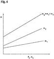
- Fig. 4 is the distribution of the total mass flow mg of the combustion-promoting gas 32 as a function of the burner power P b , and the fuel supply m b shown.
- the ratio shifts from the first mass flow m 1 to the second mass flow m 2 in the direction of the second mass flow m 2 .
- the amount of the combustion-promoting gas 32 introduced at the second introduction point 15 increases disproportionately to the amount of the gas introduced at the first introduction point.
Landscapes
- Engineering & Computer Science (AREA)
- Chemical & Material Sciences (AREA)
- Chemical Kinetics & Catalysis (AREA)
- Combustion & Propulsion (AREA)
- Mechanical Engineering (AREA)
- General Engineering & Computer Science (AREA)
- Health & Medical Sciences (AREA)
- Toxicology (AREA)
- Exhaust Gas After Treatment (AREA)
- Feeding And Controlling Fuel (AREA)
Description
- Die Erfindung betrifft eine Vorrichtung sowie ein Verfahren zur Erwärmung von Abgasen einer Brennkraftmaschine gemäß dem Oberbegriff der unabhängigen Ansprüche.
- Im Zuge der immer schärferen Schadstoffgrenzwerte für Abgase von Brennkraftmaschinen sind zahlreiche Systeme zur Abgasnachbehandlung entwickelt worden. Wird eine Brennkraftmaschine nach längerer Stillstandszeit neu gestartet und haben sich die Komponenten der Brennkraftmaschine sowie des Abgaskanals auf Umgebungstemperatur abgekühlt, benötigen die Systeme zur Abgasnachbehandlung während der sogenannten Kaltstartphase zunächst eine gewisse Zeit, bevor sie ihre Betriebstemperatur erreicht haben und entsprechende Reinigungswirkung in Bezug auf die im Abgas enthaltenen Schadstoffkomponenten erzielen. Die Aufheizung des Abgaskanals erfolgt dabei in der Regel durch das Abgas der Brennkraftmaschine, es sind jedoch auch Vorrichtungen bekannt, um die Kaltstartphase zu verkürzen und die Abgastemperatur in dieser Phase anzuheben. Aus der
DE 10 2006 060 471 ist eine Abgasanlage für eine Brennkraftmaschine bekannt, in der stromauf einer Abgasnachbehandlungseinrichtung ein Brenner zur Erhöhung der Abgastemperatur angeordnet ist, wobei der Brenner eine Brennstoffversorgung sowie eine Brennkammer mit einer Voroxidationszone und einer Nachoxidationszone aufweist. Die Voroxidationszone besitzt dabei eine Einleitstelle für Primärluft, die Nachoxidationszone eine Versorgung mit Sekundärluft. - Das Dokument
US 3,203,168 A beschreibt eine Vorrichtung zur Erwärmung von Abgasen einer Brennkraftmaschine, mit einer Brennkammer sowie einer Pumpe zur Zufuhr eines die Verbrennung fördernden Gases in die Brennkammer. Zudem sind zwei voneinander beabstandete Einleitstellen vorgesehen, welche Mittel aufweisen, die in Abhängigkeit von der Menge des zugeführten Brennstoffs ein Verhältnis zwischen einem ersten und einem zweiten Massenstrom einstellen. Die OffenlegungsschriftEP 2 253 813 A1 betrifft eine weitere Vorrichtung zur Erwärmung von Abgasen einer Brennkraftmaschine. Die Vorrichtung weist eine Brennkammer und eine Luftversorgungseinrichtung zur Zufuhr eines die Verbrennung fördernden Gases auf. Das Gas wird durch zwei Einleitstellen beziehungsweise zwei separate Leitungen in die Brennkammer eingeführt. Zusätzlich sind ein erstes und ein zweites Luftdosierelement vorgesehen, welche das Verhältnis zwischen einem ersten Massenstrom und einem zweiten Massenstrom des die Verbrennung fördernden Gases einstellen. - Die erfindungsgemäße Vorrichtung und das erfindungsgemäße Verfahren zur Erwärmung von Abgasen einer Brennkraftmaschine mit den Merkmalen der unabhängigen Ansprüche haben demgegenüber den Vorteil, dass Mittel vorgesehen sind, die in Abhängigkeit von der Menge des zugeführten Brennstoffs das Verhältnis zwischen einem ersten Massenstrom m1 des die Verbrennung fördernden Gases und einem zweiten Massenstrom m2 des die Verbrennung fördernden Gases eine Aufteilung der Massenströme m1, m2 über die beiden Einleitstellen in die Brennkammer einstellen. Dadurch ist es möglich, bei jedem Lastzustand des Brenners die Menge des zugeführten die Verbrennung fördernden Gases auf die Brennerleistung abzustimmen. Durch die in den Unteransprüchen aufgeführten Maßnahmen sind vorteilhafte Weiterbildungen und Verbesserungen der angegeben Vorrichtung bzw. des angegebenen Verfahrens möglich.
- Eine vorteilhafte Weiterbildung besteht darin, dass die Brennkammer einen ersten Bereich aufweist, in dem die Brennstoffzufuhr sowie eine erste Einleitstelle für des die Verbrennung fördernde Gas münden, und einen zweiten Bereich, in den eine zweite Einleitstelle für das die Verbrennung fördernde Gas mündet. Dadurch kann der Brennstoff in dem ersten Bereich der Brennkammer durch das die Verbrennung fördernde Gas unter Wärmeabgabe voroxidiert werden und in dem zweiten Bereich der Brennkammer, ebenfalls unter Wärmeabgabe vollständig umgesetzt werden. Dabei ist es besonders vorteilhaft, wenn der erste Bereich der Brennkammer von dem zweiten Bereich durch eine gasdurchlässige Struktur getrennt ist. Eine solche gasdurchlässige Struktur kann ein Eindringen von flüssigem Brennstoff in den zweiten Bereich der Brennkammer hemmen, so dass eine saubere Trennung von Voroxidationszone und Nachverbrennung erreicht wird, und kein flüssiger Brennstoff aus der Brennstoffzufuhr in den Abgaskanal der Brennkraftmaschine gelangt. Erfindungsgemäß, fasst die Versorgungseinrichtung eine Pumpe um. Durch eine Pumpe kann eine gleichmäßige Versorgung mit dem die Verbrennung fördernden Gas gewährleistet werden. Erfindungsgemäß ist die Pumpe über zwei separate Leitungen mit den zwei voneinander beabstandeten Einleitstellen an der Brennkammer verbunden. Dadurch kann ein erster Massenstrom m1 von der Pumpe über eine erste Leitung zu der ersten Einleitstelle und ein zweiter Massenstrom m2 von der Pumpe über eine zweite Leitung zu der zweiten Einleitstelle an der Brennkammer geführt werden.
- Dabei sind der Pumpe oder den zwei separaten Leitungen zwischen der Pumpe und den Einleitstellen die Mittel zur Aufteilung des ersten Massenstroms m1 und der zweiten Massenstroms m2 des die Verbrennung fördernden Gases zugeordnet. Über eine solche Zuordnung lässt sich eine bedarfsgerechte Aufteilung der beiden Masseströme m1 und m2 zu den jeweiligen Einleitstellen der Brennkammer darstellen.
- Erfindungsgemäß ist vorgesehen, dass Ermittlungsmittel vorhanden sind, welche die Brennstoffzufuhr zur Brennkammer ermitteln, wobei die Mittel zur Aufteilung der beiden Massenströme die beiden Massenströme m1 und m2 des die Verbrennung fördernden Gases in Abhängigkeit der durch die Ermittlungsmittel festgestellten Zufuhr des Brennstoffs aufteilen. Über solche Ermittlungsmittel lässt sich leicht der zu der jeweiligen Brennerleistung gehörende Bedarf an dem die Verbrennung fördernden Gas ermitteln, so dass die Aufteilung bedarfsgerecht gesteuert werden kann. Erfindungsgemäß ist vorgesehen, dass eine Leistung der Pumpe in Abhängigkeit der durch die Ermittlungsmittel festgestellten Zufuhr des Brennstoffs gesteuert oder geregelt wird. Die bedarfsgerechte Regelung der Pumpe zur Bereitstellung des die Verbrennung fördernden Gases lässt sich dabei einfach über die zugeführte Brennstoffmenge steuern.
- Dabei ist es besonders vorteilhaft, dass die Mittel zur Aufteilung des Massenströme m1, m2 eine derartige Aufteilung der beiden Massenströme m1, m2 durchführen, dass mit steigender Zufuhr des Brennstoffs eine Zufuhr des die Verbrennung fördernden Gases zum zweiten Bereich der Brennkammer überproportional zur Zufuhr des die Verbrennung fördernden Gases zum ersten Bereich der Brennkammer ansteigt. Dadurch wird bei niedrigen Brennerleistungen mehr von dem die Verbrennung fördernden Gas in den ersten Bereich der Brennkammer geleitet, wobei es zu einer stärkeren Voroxidation kommt und bei höheren Brennerleistungen mehr von dem die Verbrennung fördernden Gas in den zweiten Bereich der Brennkammer geleitet, wodurch es zu einer stärkeren Nachoxidation und einer stärkeren Wärmefreisetzung in diesem zweiten Bereich der Brennkammer kommt.
- Eine weitere vorteilhafte Weiterbildung besteht darin, dass die Mittel zur Aufteilung der Massenströme m1, m2 zumindest in einer der beiden separaten Leitungen Mittel zur Beeinflussung des Strömungswiderstandes umfassen. Über die Veränderung des Strömungswiderstandes in den beiden Leitungen lässt sich die Aufteilung der beiden Massenströme m1, m2 in Abhängigkeit der Leistung der Pumpe beeinflussen, ohne dass zusätzliche bewegliche Bauteile benötigt werden.
- Dabei ist es insbesondere vorteilhaft, dass die Mittel zur Beeinflussung des Strömungswiderstandes in einer Leitung eine laminare Strömung und in der anderen Leitung eine turbulente Strömung ausbilden. Bei einer laminaren Strömung steigt der Strömungswiderstand mit der Strömungsgeschwindigkeit proportional an, während bei einer turbulenten Strömung der Strömungswiderstand quadratisch mit der Strömungsgeschwindigkeit steigt. Dadurch verschiebt sich die Aufteilung des Gesamtmassenstroms mg in die beiden Massenströme m1, m2 zugunsten der Leitung, in der die laminare Strömung ausgebildet ist.
- Dabei ist es insbesondere vorteilhaft, wenn die Mittel zur Beeinflussung des Strömungswiderstandes aus Wellblech, Metallgewebe und/oder Metallgestrick gebildet sind. Leitbleche oder Turbulenz erzeugende Elemente aus Wellblech, Metallgewebe und/oder Metallgestrick sind für die in der Nähe des Abgasstrangs herrschenden Umweltbedingungen bzgl. Temperatur und Korrosionswiderstand gut geeignet und lassen sich preisgünstig in die Leitungen integrieren.
- Eine weitere vorteilhafte Weiterbildung besteht darin, dass in den zwei separaten Leitungen verstellbare Drosseln zur Einstellung des Verhältnisses zwischen dem ersten Massenstrom m1 und dem zweiten Massenstrom m2 des die Verbrennung fördernden Gases angeordnet sind. Über entsprechende verstellbare Drosseln kann der Querschnitt bzw. der Strömungswiderstand in den einzelnen Leitungen und damit verbunden der Durchfluss durch die jeweilige Leitung verstellt werden. Somit sind auch Drosseln ein einfaches und geeignetes Mittel zur bedarfsgerechten Aufteilung der beiden Massenströme m1, m2 zu den beiden Einleitstellen der Brennkammer.
- Ausführungsbeispiele der Erfindung sind in den Zeichnungen dargestellt und in der nachfolgenden Beschreibung näher erläutert
- In
Fig. 1 ist ein erstes Ausführungsbeispiel einer erfindungsgemäßen Vorrichtung zur Erwärmung von Abgasen einer Brennkraftmaschine gezeigt. - In
Fig. 2 ist ein weiteres Ausführungsbeispiel einer erfindungsgemäßen Vorrichtung zur Erwärmung von Abgasen einer Brennkraftmaschine gezeigt. - In
Fig. 3a ist ein Schnitt durch eine Leitung der erfindungsgemäßen Vorrichtung gezeigt. - In
Fig. 3b ist ein weiterer Schnitt durch eine Leitung der erfindungsgemäßen Vorrichtung gezeigt. - In
Fig. 4 ist ein Aufteilung eines Gesamtmassenstroms eines die Verbrennung fördenden Gases in zwei Teilmassenströme in Abhängigkeit von der Brennerleistung dargestellt. - Die erfindungsgemäße Vorrichtung umfasst eine Brennkammer 10, welche durch eine gasdurchlässige Struktur 18 in einen ersten Bereich 12 und einen zweiten Bereich 14 unterteilt ist. Der zweite Bereich 14 der Brennkammer mündet in einen Abgaskanal 60 einer Brennkraftmaschine. Eine Versorgungseinheit 30 ist über eine erste Leitung 34 mit einer ersten Einleitstelle 13 in dem ersten Bereich 12 der Brennkammer 10 verbunden. Die Versorgungseinheit 30 ist zusätzlich über eine zweite Leitung 36 mit einer zweiten Einleitstelle 15, welche am zweiten Bereich 14 der Brennkammer 10 ausgebildet ist, verbunden. Am ersten Bereich 12 der Brennkammer 10 ist zentrisch eine Brennstoffzufuhr 20 angeordnet, mit der ein Brennstoff 22 in die Brennkammer 10 eingeleitet werden kann. An dem ersten Bereich 12 der Brennkammer 10 ist eine Zündvorrichtung 16 angeordnet, über welche ein Gemisch aus dem Brennstoff 22 und einem, über die Einleitstelle 13 zugeführten, die Verbrennung fördernden Gas 32 gezündet werden kann.
- Im Betrieb der Vorrichtung wird der Brennstoff 22 durch die Brennstoffzufuhr 20 in den ersten Bereich 12 der Brennkammer 10 eingeleitet. Parallel dazu wird ein die Verbrennung förderndes Gas 32, beispielsweise Luft oder Sauerstoff, durch die Versorgungseinrichtung 30 über die Leitung 34 dem ersten Bereich 12 der Brennkammer 10 zugeführt, wo sich der Brennstoff 22 und das die Verbrennung fördernde Gas 32 vermischen und über die Zündvorrichtung 16 entflammt werden. Das entflammte Gasgemisch strömt unter Wärmeabgabe durch die gasdurchlässige Struktur 18, wobei dem Gasgemisch im zweiten Bereich 14 der Brennkammer durch die Versorgungseinrichtung 30 und die zweite Leitung 36 über die zweite Einleitstelle 15 nochmals das die Verbrennung fördernde Gas 32 zugeführt wird. In dem zweiten Bereich 14 der Brennkammer 10 wird das Gasgemisch aus dem Brennstoff 22 und dem die Verbrennung fördernden Gas 32 nochmals unter Freisetzung von Wärme oxidiert, wobei Verbrennungsprodukte des Gasgemischs in den Abgaskanal 60 der Brennkraftmaschine eingeleitet werden und dort eine in Strömungsrichtung folgende Abgasnachbehandlungseinrichtung, beispielsweise einen Oxidationskatalysator oder einen Partikelfilter, erwärmen.
- In
Fig. 2 ist ein alternatives Ausführungsbeispiels einer erfindungsgemäßen Vorrichtung zu Erwärmung von Abgasen einer Brennkraftmaschine dargestellt. Die Vorrichtung weist als Versorgungseinrichtung 30 eine Pumpe 40 auf, an welcher ein erster Auslass 42 und ein zweiter Auslass 44 ausgebildet sind. Der erste Auslass der Pumpe 40 ist über die erste Leitung 34 mit der ersten Einleitstelle 13 an dem ersten Bereich 10 der Brennkammer 10 verbunden, wobei in der ersten Leitung 34 Mittel 37 zur Beeinflussung des Strömungswiderstandes in der ersten Leitung 34 angeordnet. Die zweite Leitung 36 verbindet den zweiten Auslass 44 der Pumpe 40 mit der zweiten Einleitstelle 15 an dem zweiten Bereich 14 der Brennkammer 10, wobei der erste Bereich 12 und der zweite Bereich 14 durch eine gasdurchlässige Struktur 18, beispielsweise ein Metallgeflecht, getrennt sind, welche ein Eindringen von flüssigem Brennstoff 22 in den zweiten Bereich 14 der Brennkammer hindert. An dem ersten Bereich 12 der Brennkammer 10 ist zentrisch die Brennstoffversorgung 20 angeordnet, welche einen, bevorzugt flüssigen, Brennstoff 22 in den ersten Bereich 12 der Brennkammer 10 leitet. Die erste Einleitstelle 13 umgibt die Brennstoffzufuhr 20 ringförmig, wodurch eine möglichst gleichmäßig Verteilung des über die erste Einleitstelle 13 in den ersten Bereich 12 der Brennkammer 10 zugeführten, die Verbrennung fördernden Gases 32 erreicht wird. Ferner ist an dem ersten Bereich 12 der Brennkammer die Zündvorrichtung 16 angeordnet, welche den Brennstoff 22 bzw. ein Gemisch aus dem Brennstoff und dem die Verbrennung fördernden Gas 32 zündet. An der Brennstoffzufuhr sind Ermittlungsmittel 24 zur Erfassung der zugeführten Menge des Brennstoffs 22 in die Brennkammer 10, beispielsweise ein Durchflussmessgerät, angeordnet. An der Pumpe 40 sind Mittel 45 vorgesehen, die einen Gesamtmassenstrom mg des die Verbrennung fördernden Gases 32 in Abhängigkeit der Menge des zugeführten Brennstoffs 22 in einen ersten Massenstrom m1 des die Verbrennung fördernden Gases 32 durch die erste Leitung 34 und einen zweiten Massenstrom m2 des die Verbrennung fördernden Gases 32 durch die zweite Leitung 36 aufteilen. Im einfachsten Ausführungsbeispiel erfolgt die Aufteilung des Gesamtmassenstroms mg in die beiden Massenströme m1 und m2 ohne zusätzliche, mechanisch verstellbaren Elemente allein über den Strömungswiderstand in den beiden Leitungen 34 und 36, wobei in der ersten Leitung 34 eine laminare Strömung mit proportional zu Strömungsgeschwindigkeit steigendem Strömungswiderstand ausgebildet ist, während in der zweiten Leitung 36 eine turbulente Strömung mit quadratisch zur Strömungsgeschwindigkeit steigendem Strömungswiderstand ausgebildet ist. Dies kann zum einen durch eine entsprechende Wahl von Rauhigkeit und Leitungsquerschnitt in den Leitungen 34, 36 erreicht werden, zusätzlich können aber auch Mittel 37 zur Beeinflussung des Strömungswiderstandes wie Turbulenzelemente oder Leitschaufeln in den Leitungen angeordnet sein. Ein Beispiel für ein solches Mittel 37 in der ersten Leitung 34 ist inFig. 3a dargestellt. Als Material für solche Mittel 37 eignet sich aufgrund der Anfordungen bezüglich Korrosions- und Temperaturfestigkeit beispielsweise Wellblech, Metallgewebe und/oder Metallgestrick. - Durch die unterschiedlich stark steigenden Strömungswiderstände in den Leitungen 34, 36 verändert sich das Verhältnis des zugeführten, die Verbrennung fördernden Gases 32 in Abhängigkeit von der Fördermenge, bzw. Drehzahl der Pumpe 40. Dabei wird die Drehzahl bzw. Fördermenge der Pumpe 40 in Abhängigkeit der durch die Ermittlungsmittel 24 ermittelten Zufuhr des Brennstoffs 22 gesteuert oder geregelt. Die Vermischung des Brennstoffs 22 und des die Verbrennung fördernden Gases 32 erfolgt gemäß den Ausführungen zu
Fig. 1 . - Alternativ kann sowohl die Brennstoffzufuhr 20 als auch die erste Einleitstelle 13 exzentrisch angeordnet sein, bzw. kann die erste Einleitstelle 13 auch an anderer Stelle des ersten Bereichs 12 der Brennkammer 10 angeordnet sein. Alternativ bzw. zusätzlich können auch in der zweiten Leitung 36 Mittel 37 zur Beeinflussung des Strömungswiderstandes angeordnet sein.
- Alternativ können anstelle einer Pumpe 40 auch zwei Pumpen eingesetzt werden, wobei dann jeweils eine Pumpe über eine Leitung 34, 36 mit jeweils einer Einleitstelle 13, 15 an der Brennkammer 10 verbunden ist. Ferner ist es möglich, dass die Mittel 45, die in Abhängigkeit von der Menge des zugeführten Brennstoffs 22 das Verhältnis zwischen dem ersten Massenstrom m1 und dem zweiten Massenstrom m2 einstellen einen Aktuator, beispielsweise einen Schieberegler, umfassen, welcher die Luftverteilung von der Pumpe 40 zu den beiden Leitungen 34, 36 steuert. Alternativ kann die Pumpe 40 auch über eine Leitung 34 mit der Brennkammer 10 verbunden sein, wobei die Aufteilung der beiden Massenströme m1 und m2 auf die beiden Einleitstellen 13, 15 erst an der Brennkammer erfolgt.
- Die Pumpe 40 ist bevorzugt als Klauenpumpe ausgebildet, alternativ kann die Pumpe jedoch auch als Kreiselpumpe oder Kolbenpumpe ausgebildet sein. Die Verwendung einer Klauen-Pumpe, beispielsweise eines sogenannten "Roots-Gebläses", bietet den Vorteil, dass bei niedrigen Drehzahlen, d.h. niedriger Fördermenge der Pumpe, die Strömung des die Verbrennung fördernden Gases 32 gleichmäßig auf die beiden Auslässe 42, 44 verteilt, während mit steigender Pumpendrehzahl die Fliehkräfte zunehmen, wodurch sich die Verteilung des die Verbrennung fördernden Gases in Richtung des Auslasses 44 bzw. der zweiten Leitung 36 verschiebt.
- Alternativ können die Mittel 45, die in Abhängigkeit von der Menge des zugeführten Brennstoffs 22 das Verhältnis zwischen dem ersten Massenstrom m1 und dem zweiten Massenstrom m2 einstellen, wie in
Fig. 3b dargestellt verstellbare Blenden 35 in den Leitungen 34, 36 umfassen, mit denen das Verhältnis der zugeführten Menge des die Verbrennung fördernden Gases 32 zu den Einleitstellen 13, 15 verstellt werden kann. - In
Fig. 4 ist die Aufteilung des Gesamtmassenstroms mg des die Verbrennung fördernden Gases 32 in Abhängigkeit von der Brennerleistung Pb, bzw. der Brennstoffzufuhr mb dargestellt. Mit steigender Brennstoffzufuhr verschiebt sich das Verhältnis von dem ersten Massenstrom m1 zum zweiten Massenstrom m2 in Richtung des zweiten Massenstroms m2. Bei höherer Brennstoffzufuhr steigt also die Menge des an der zweiten Einleitstelle 15 eingeleiteten die Verbrennung fördernden Gases 32 überproportional zu der Menge des an der ersten Einleitstelle eingeleiteten Gases an. Während bei niedriger Brennerleistung etwa 40% des die Verbrennung fördernden Gases 32 an der ersten Einleitstelle 13 und etwa 60% an der zweiten Einleitstelle 15 zugeführt werden, verschiebt sich das Verhältnis mit steigender Brennstoffzufuhr in etwa zu 20% an der ersten Einleitstelle 13 und 80% an der zweiten Einleistelle 15, wobei die Menge des die Verbrennung fördernden Gases 32 an beiden Einleitstellen 13, 15 mit zunehmender Zufuhr des Brennstoffs 22 ansteigt.
Claims (11)
- Vorrichtung zur Erwärmung von Abgasen einer Brennkraftmaschine, mit einer Brennkammer (10), einer Brennstoffversorgung (20) zur Zufuhr eines, vorzugsweise flüssigen, Brennstoffs (22), sowie einer Versorgungseinrichtung (30) zur Zufuhr eines die Verbrennung fördernden Gases (32) in die Brennkammer (10) über zwei voneinander beabstandete Einleitstellen (13, 15), wobei Mittel (45) vorgesehen sind, die in Abhängigkeit von der Menge des zugeführten Brennstoffs (22) das Verhältnis zwischen einem ersten Massenstrom m1 des die Verbrennung fördernden Gases (32) und einem zweiten Massenstrom m2 des die Verbrennung fördernden Gases (32) eine Aufteilung der Massenströme m1, m2 über die beiden Einleitstellen (13, 15) in die Brennkammer (10) einstellen, wobei die Versorgungseinrichtung (30) eine Pumpe (40) umfasst, und wobei die Pumpe (40) über zwei separate Leitungen (34, 36) mit den zwei voneinander beabstandeten Einleitstellen (13, 15) verbunden ist, wobei der Pumpe (40) oder den zwei separaten Leitungen (34 , 36) zwischen der Pumpe (40) und den Einleitstellen (13, 15) die Mittel (45) zur Aufteilung des ersten Massenstroms m1 und des zweiten Massenstroms m2 des die Verbrennung fördernden Gases (32) zugeordnet sind, dadurch gekennzeichnet, dass an der Brennstoffversorgung (20) Ermittlungsmittel (24) angeordnet sind, welche die Brennstoffzufuhr zur Brennkammer (10) ermitteln, wobei die Mittel ( 45) zur Aufteilung des ersten Massenstroms m1 und des zweiten Massenstroms m2 die beiden Massenströme m1, m2 in Abhängigkeit der durch die Ermittlungsmittel (24) festgestellte Zufuhr des Brennstoff (22) aufteilen, und wobei eine Leistung der Pumpe (40) in Abhängigkeit der durch die Ermittlungsmittel (24) festgestellte Zufuhr des Brennstoffs (22) gesteuert oder geregelt wird.
- Vorrichtung nach Anspruch 1, dadurch gekennzeichnet, dass die Brennkammer (10) einen ersten Bereich (12) aufweist, in dem die Brennstoffzufuhr (20) sowie eine erste Einleitstelle (13) für das die Verbrennung fördernde Gas (32) münden, und einen zweiten Bereich (14), in den eine zweite Einleitstelle (15) für das die Verbrennung fördernde Gas (32) mündet.
- Vorrichtung nach Anspruch 2, dadurch gekennzeichnet, dass der erste Bereich (12) der Brennkammer (10) von dem zweiten Bereich (14) durch eine gasdurchlässige Struktur (18) getrennt ist.
- Vorrichtung nach einem der vorhergehenden Ansprüche, dass die Mittel zur Aufteilung eine derartige Aufteilung der Massenströme m1, m2 durchführen, dass mit steigender Zufuhr des Brennstoffs (22) eine Zufuhr des die Verbrennung fördernden Gases (32) zum zweiten Bereich (14) der Brennkammer (10) überproportional zur Zufuhr des die Verbrennung fördernden Gases (32) zum ersten Bereich (12) der Brennkammer (10) ansteigt.
- Vorrichtung nach einem der vorhergehenden Ansprüche, dadurch gekennzeichnet, dass die Mittel (45) zur Aufteilung der Massenströme m1, m2 zumindest in einer der zwei separaten Leitungen (34, 36) Mittel (37) zur Beeinflussung des Strömungswiderstandes umfassen.
- Vorrichtung nach Anspruch 5, dadurch gekennzeichnet, dass die Mittel (37) zur Beeinflussung des Strömungswiderstandes eine laminare Strömung bilden.
- Vorrichtung nach Anspruch 5, dadurch gekennzeichnet, dass die Mittel (37) zur Beeinflussung des Strömungswiderstandes eine turbulente Strömung bilden.
- Vorrichtung nach Anspruch 6 oder 7, dadurch gekennzeichnet, dass die Mittel (37) zur Beeinflussung des Strömungswiderstandes aus Wellblech, Metallgewebe und/oder Metallgestrick gebildet sind.
- Vorrichtung nach einem der vorhergehenden Ansprüche, dadurch gekennzeichnet, dass an oder in den zwei separaten Leitungen (34 , 36) verstellbare Drosseln (35) zur Einstellung des Verhältnisses zwischen dem ersten Massenstrom m1 und dem zweiten Massenstrom m2 des die Verbrennung fördernden Gases (32) angeordnet sind.
- Abgasanlage mit einer Vorrichtung nach einem der Ansprüche 1 bis 9.
- Verfahren zur Erwärmung von Abgasen einer Brennkraftmaschine, wobei ein, vorzugsweise flüssiger, Brennstoff (22) durch eine Brennstoffversorgung ( 20) einer Brennkammer (10) zugeführt wird und wobei der Brennkammer (10) durch eine Versorgungseinrichtung (30) über zwei voneinander beabstandeten Einleitstellen (13, 15) ein die Verbrennung förderndes Gas (32) zugeführt wird, wobei in Abhängigkeit von der Menge des zugeführten Brennstoffs (22) das Verhältnis zwischen einem ersten Massenstrom m1 des die Verbrennung fördernden Gases (32) und einem zweiten Massenstrom m2 des die Verbrennung fördernden Gases (32) zu den zwei voneinander beabstandeten Einleitstellen (13, 15) eingestellt wird, wobei eine Pumpe (40) der Versorgungseinrichtung (30) über zwei separate Leitungen (34 , 36) mit den zwei voneinander beabstandeten Einleitstellen (13, 15) verbunden wird, wobei der Pumpe (40) oder den zwei separaten Leitungen (34, 36) zwischen der Pumpe (40) und den Einleitstellen (13 , 15) Mittel (45) zur Aufteilung des ersten Massenstroms m1 und des zweiten Massenstroms m2 des die Verbrennung fördernden Gases (32) zugeordnet werden, dadurch gekennzeichnet, dass eine Brennstoffzufuhr in die Brennkammer (10) erfasst wird, wobei die beiden Massenströme m1, m2 in Abhängigkeit der festgestellten Zufuhr des Brennstoffs (22) aufgeteilt werden, und wobei eine Leistung der Pumpe (40) in Abhängigkeit der festgestellten Zufuhr des Brennstoffs (22) gesteuert oder geregelt wird.
Applications Claiming Priority (2)
| Application Number | Priority Date | Filing Date | Title |
|---|---|---|---|
| DE102011007461A DE102011007461A1 (de) | 2011-04-15 | 2011-04-15 | Vorrichtung und Verfahren zur Erwärmung von Abgasen einer Brennkraftmaschine |
| PCT/EP2012/053153 WO2012139801A1 (de) | 2011-04-15 | 2012-02-24 | Vorrichtung und verfahren zur erwärmung von abgasen einer brennkraftmaschine |
Publications (2)
| Publication Number | Publication Date |
|---|---|
| EP2697489A1 EP2697489A1 (de) | 2014-02-19 |
| EP2697489B1 true EP2697489B1 (de) | 2017-08-02 |
Family
ID=45768214
Family Applications (1)
| Application Number | Title | Priority Date | Filing Date |
|---|---|---|---|
| EP12706032.5A Not-in-force EP2697489B1 (de) | 2011-04-15 | 2012-02-24 | Vorrichtung und verfahren zur erwärmung von abgasen einer brennkraftmaschine |
Country Status (4)
| Country | Link |
|---|---|
| EP (1) | EP2697489B1 (de) |
| CN (1) | CN103459797B (de) |
| DE (1) | DE102011007461A1 (de) |
| WO (1) | WO2012139801A1 (de) |
Families Citing this family (14)
| Publication number | Priority date | Publication date | Assignee | Title |
|---|---|---|---|---|
| CN107965386A (zh) * | 2017-11-27 | 2018-04-27 | 林晓丽 | 一种发动机蜗轮增压器 |
| IT202000022396A1 (it) | 2020-09-23 | 2022-03-23 | Marelli Europe Spa | Dispositivo riscaldatore per un sistema di scarico di un motore a combustione interna |
| US11674427B2 (en) | 2020-12-23 | 2023-06-13 | Marelli Europe S.P.A. | Heating device for an exhaust system of an internal combustion engine |
| IT202100001892A1 (it) | 2021-01-29 | 2022-07-29 | Marelli Europe Spa | Dispositivo riscaldatore per un sistema di scarico di un motore a combustione interna |
| IT202100001880A1 (it) | 2021-01-29 | 2022-07-29 | Marelli Europe Spa | Dispositivo riscaldatore per un sistema di scarico di un motore a combustione interna |
| IT202100001871A1 (it) | 2021-01-29 | 2022-07-29 | Marelli Europe Spa | Dispositivo riscaldatore per un sistema di scarico di un motore a combustione interna |
| EP4056818B1 (de) | 2021-02-26 | 2023-11-22 | Marelli Europe S.p.A. | Heizvorrichtung für ein auspuffsystem eines verbrennungsmotors |
| IT202100023678A1 (it) | 2021-09-14 | 2023-03-14 | Marelli Europe Spa | Dispositivo riscaldatore per un sistema di scarico di un motore a combustione interna |
| IT202100023672A1 (it) | 2021-09-14 | 2023-03-14 | Marelli Europe Spa | Dispositivo riscaldatore per un sistema di scarico di un motore a combustione interna |
| IT202100029297A1 (it) | 2021-11-19 | 2023-05-19 | Marelli Europe Spa | Metodo di controllo di un dispositivo riscaldatore per un sistema di scarico di un motore a combustione interna |
| EP4202193B1 (de) | 2021-12-21 | 2024-11-20 | Marelli Europe S.p.A. | Heizvorrichtung für ein abgassystem eines verbrennungsmotors und zugehöriges steuerungsverfahren |
| IT202200006179A1 (it) | 2022-03-29 | 2023-09-29 | Marelli Europe Spa | Dispositivo riscaldatore per un sistema di scarico di un motore a combustione interna |
| IT202200024240A1 (it) | 2022-11-24 | 2024-05-24 | Marelli Europe Spa | Dispositivo riscaldatore per un sistema di scarico di un motore a combustione interna |
| IT202300013269A1 (it) | 2023-06-27 | 2024-12-27 | Marelli Europe Spa | Dispositivo riscaldatore per un sistema di scarico di un motore a combustione interna |
Family Cites Families (9)
| Publication number | Priority date | Publication date | Assignee | Title |
|---|---|---|---|---|
| US3203168A (en) * | 1962-05-21 | 1965-08-31 | Oxy Catalyst Inc | Method and apparatus for improving the purification of exhaust gases from an internal combustion engine |
| DE1594710C3 (de) * | 1965-10-28 | 1974-03-07 | Linde, Robert Von, Dipl.-Ing., 8032 Graefelfing | Verfahren zur katalytischen Reinigung sauerstoffhaltig« Abgase |
| JPH0674728B2 (ja) * | 1983-07-15 | 1994-09-21 | 三菱電機株式会社 | デイ−ゼル排出ガス浄化装置におけるバ−ナエア制御システム |
| US7032376B1 (en) * | 2003-08-27 | 2006-04-25 | Southwest Research Institute | Diesel fuel burner for diesel emissions control system |
| DE502005007492D1 (de) * | 2004-10-01 | 2009-07-30 | Eberspaecher J Gmbh & Co | Abgasanlage für eine Brennkraftmaschine und zugehöriges Betriebsverfahren |
| DE102006060471A1 (de) * | 2006-12-19 | 2008-06-26 | J. Eberspächer GmbH & Co. KG | Abgasanlage für eine Brennkraftmaschine |
| KR100866327B1 (ko) * | 2007-07-30 | 2008-10-31 | 한국기계연구원 | 플라즈마 버너 및 매연여과장치 |
| US8257455B2 (en) * | 2007-07-30 | 2012-09-04 | Korea Institute Of Machinery & Materials | Plasma burner and diesel particulate filter trap |
| JP5285296B2 (ja) * | 2008-02-22 | 2013-09-11 | ヤンマー株式会社 | 排気ガス浄化装置 |
-
2011
- 2011-04-15 DE DE102011007461A patent/DE102011007461A1/de not_active Withdrawn
-
2012
- 2012-02-24 WO PCT/EP2012/053153 patent/WO2012139801A1/de not_active Ceased
- 2012-02-24 CN CN201280017894.4A patent/CN103459797B/zh not_active Expired - Fee Related
- 2012-02-24 EP EP12706032.5A patent/EP2697489B1/de not_active Not-in-force
Non-Patent Citations (1)
| Title |
|---|
| None * |
Also Published As
| Publication number | Publication date |
|---|---|
| DE102011007461A1 (de) | 2012-10-18 |
| EP2697489A1 (de) | 2014-02-19 |
| WO2012139801A1 (de) | 2012-10-18 |
| CN103459797A (zh) | 2013-12-18 |
| CN103459797B (zh) | 2017-04-19 |
Similar Documents
| Publication | Publication Date | Title |
|---|---|---|
| EP2697489A1 (de) | Vorrichtung und verfahren zur erwärmung von abgasen einer brennkraftmaschine | |
| DE102015212514B4 (de) | Verfahren zur Abgasnachbehandlung und Vorrichtung zur Reinigung des Abgases einer Brennkraftmaschine | |
| EP2588805B1 (de) | Brenneranordnung | |
| EP0599060B1 (de) | Brennersystem zur Abgasentgiftung bzw. -reinigung einer Brennkraftmaschine | |
| DE102016206394B4 (de) | Verfahren und Vorrichtung zur Abgasnachbehandlung eines Verbrennungsmotors | |
| DE102015207595B3 (de) | Verfahren zum Regenerieren eines NOx-Speicherkatalysators eines eine Zylinderabschaltung aufweisenden Verbrennungsmotors und Vorrichtung zum Durchführen des Verfahrens | |
| DE4025017A1 (de) | Abgasleitung mit einem partikelfilter und einem regenerierungsbrenner | |
| CH698400B1 (de) | Brennstoffdüse. | |
| DE102016214954A1 (de) | Gasförmiger Brennstoff, AGR und Luftmischvorrichtung plus Einsatz | |
| DE102008032601A1 (de) | Verfahren zum Einstellen eines Zustandes eines Abgasstroms einer Brennkraftmaschine eines Kraftfahrzeuges | |
| EP1108862B1 (de) | Verfahren und Vorrichtung zum Reduzieren schädlicher Bestandteile im Abgas einer Brennkraftmaschine | |
| DE102009032022A1 (de) | Verfahren und Vorrichtung zur Regeneration eines im Abgastrakt einer Brennkraftmaschine angeordneten Partikelfilters | |
| DE102011006241A1 (de) | Vorrichtung zum Mischen von Treibstoff und Luft eines Strahltriebwerks | |
| DE102005054733A1 (de) | Brenner zur Katalysatoraufheizung mit gesteuerter oder geregelter Kraftstoffzuführung | |
| CH704827B1 (de) | Abgasnutzturbine, Abwärmerückgewinnungssystem und Verfahren zum Betreiben eines Abwärmerückgewinnungssystems. | |
| WO2006021543A1 (de) | Mischeranordnung | |
| DE2849945C2 (de) | Abgasturbolader für eine Brennkraftmaschine | |
| EP2583033B1 (de) | Turbinenbrenner | |
| EP1255077A2 (de) | Vorrichtung zum Verbrennen eines gasförmigen Brennstoff-Oxidator-Gemischs | |
| EP4314503A1 (de) | Verfahren zum betreiben eines brenners eines kraftfahrzeugs | |
| EP2957831B1 (de) | Brenner und verfahren zum betrieb solch eines brenners | |
| DE102013204401B4 (de) | System zur Abgasnachbehandlung, Verfahren und Brennkraftmaschine | |
| WO2010142560A1 (de) | Mischelement für den ansaugstrom von gasturbinen | |
| DE4303625B4 (de) | Verfahren zur Regeneration von Partikelfiltersystemen | |
| DE102014104454A1 (de) | Turbomaschinensystem mit einfachem Kreisprozess und Kraftstoffkondfitionierungssystem |
Legal Events
| Date | Code | Title | Description |
|---|---|---|---|
| PUAI | Public reference made under article 153(3) epc to a published international application that has entered the european phase |
Free format text: ORIGINAL CODE: 0009012 |
|
| 17P | Request for examination filed |
Effective date: 20131115 |
|
| AK | Designated contracting states |
Kind code of ref document: A1 Designated state(s): AL AT BE BG CH CY CZ DE DK EE ES FI FR GB GR HR HU IE IS IT LI LT LU LV MC MK MT NL NO PL PT RO RS SE SI SK SM TR |
|
| DAX | Request for extension of the european patent (deleted) | ||
| 17Q | First examination report despatched |
Effective date: 20160705 |
|
| GRAP | Despatch of communication of intention to grant a patent |
Free format text: ORIGINAL CODE: EPIDOSNIGR1 |
|
| GRAJ | Information related to disapproval of communication of intention to grant by the applicant or resumption of examination proceedings by the epo deleted |
Free format text: ORIGINAL CODE: EPIDOSDIGR1 |
|
| INTG | Intention to grant announced |
Effective date: 20170321 |
|
| GRAP | Despatch of communication of intention to grant a patent |
Free format text: ORIGINAL CODE: EPIDOSNIGR1 |
|
| INTC | Intention to grant announced (deleted) | ||
| INTG | Intention to grant announced |
Effective date: 20170428 |
|
| GRAS | Grant fee paid |
Free format text: ORIGINAL CODE: EPIDOSNIGR3 |
|
| GRAA | (expected) grant |
Free format text: ORIGINAL CODE: 0009210 |
|
| AK | Designated contracting states |
Kind code of ref document: B1 Designated state(s): AL AT BE BG CH CY CZ DE DK EE ES FI FR GB GR HR HU IE IS IT LI LT LU LV MC MK MT NL NO PL PT RO RS SE SI SK SM TR |
|
| REG | Reference to a national code |
Ref country code: CH Ref legal event code: EP Ref country code: AT Ref legal event code: REF Ref document number: 914745 Country of ref document: AT Kind code of ref document: T Effective date: 20170815 |
|
| REG | Reference to a national code |
Ref country code: IE Ref legal event code: FG4D Free format text: LANGUAGE OF EP DOCUMENT: GERMAN |
|
| REG | Reference to a national code |
Ref country code: DE Ref legal event code: R096 Ref document number: 502012010911 Country of ref document: DE |
|
| REG | Reference to a national code |
Ref country code: NL Ref legal event code: MP Effective date: 20170802 |
|
| REG | Reference to a national code |
Ref country code: LT Ref legal event code: MG4D |
|
| PG25 | Lapsed in a contracting state [announced via postgrant information from national office to epo] |
Ref country code: HR Free format text: LAPSE BECAUSE OF FAILURE TO SUBMIT A TRANSLATION OF THE DESCRIPTION OR TO PAY THE FEE WITHIN THE PRESCRIBED TIME-LIMIT Effective date: 20170802 Ref country code: NO Free format text: LAPSE BECAUSE OF FAILURE TO SUBMIT A TRANSLATION OF THE DESCRIPTION OR TO PAY THE FEE WITHIN THE PRESCRIBED TIME-LIMIT Effective date: 20171102 Ref country code: LT Free format text: LAPSE BECAUSE OF FAILURE TO SUBMIT A TRANSLATION OF THE DESCRIPTION OR TO PAY THE FEE WITHIN THE PRESCRIBED TIME-LIMIT Effective date: 20170802 Ref country code: FI Free format text: LAPSE BECAUSE OF FAILURE TO SUBMIT A TRANSLATION OF THE DESCRIPTION OR TO PAY THE FEE WITHIN THE PRESCRIBED TIME-LIMIT Effective date: 20170802 Ref country code: NL Free format text: LAPSE BECAUSE OF FAILURE TO SUBMIT A TRANSLATION OF THE DESCRIPTION OR TO PAY THE FEE WITHIN THE PRESCRIBED TIME-LIMIT Effective date: 20170802 Ref country code: SE Free format text: LAPSE BECAUSE OF FAILURE TO SUBMIT A TRANSLATION OF THE DESCRIPTION OR TO PAY THE FEE WITHIN THE PRESCRIBED TIME-LIMIT Effective date: 20170802 |
|
| REG | Reference to a national code |
Ref country code: FR Ref legal event code: PLFP Year of fee payment: 7 |
|
| PG25 | Lapsed in a contracting state [announced via postgrant information from national office to epo] |
Ref country code: ES Free format text: LAPSE BECAUSE OF FAILURE TO SUBMIT A TRANSLATION OF THE DESCRIPTION OR TO PAY THE FEE WITHIN THE PRESCRIBED TIME-LIMIT Effective date: 20170802 Ref country code: PL Free format text: LAPSE BECAUSE OF FAILURE TO SUBMIT A TRANSLATION OF THE DESCRIPTION OR TO PAY THE FEE WITHIN THE PRESCRIBED TIME-LIMIT Effective date: 20170802 Ref country code: BG Free format text: LAPSE BECAUSE OF FAILURE TO SUBMIT A TRANSLATION OF THE DESCRIPTION OR TO PAY THE FEE WITHIN THE PRESCRIBED TIME-LIMIT Effective date: 20171102 Ref country code: RS Free format text: LAPSE BECAUSE OF FAILURE TO SUBMIT A TRANSLATION OF THE DESCRIPTION OR TO PAY THE FEE WITHIN THE PRESCRIBED TIME-LIMIT Effective date: 20170802 Ref country code: LV Free format text: LAPSE BECAUSE OF FAILURE TO SUBMIT A TRANSLATION OF THE DESCRIPTION OR TO PAY THE FEE WITHIN THE PRESCRIBED TIME-LIMIT Effective date: 20170802 Ref country code: IS Free format text: LAPSE BECAUSE OF FAILURE TO SUBMIT A TRANSLATION OF THE DESCRIPTION OR TO PAY THE FEE WITHIN THE PRESCRIBED TIME-LIMIT Effective date: 20171202 Ref country code: GR Free format text: LAPSE BECAUSE OF FAILURE TO SUBMIT A TRANSLATION OF THE DESCRIPTION OR TO PAY THE FEE WITHIN THE PRESCRIBED TIME-LIMIT Effective date: 20171103 |
|
| PG25 | Lapsed in a contracting state [announced via postgrant information from national office to epo] |
Ref country code: DK Free format text: LAPSE BECAUSE OF FAILURE TO SUBMIT A TRANSLATION OF THE DESCRIPTION OR TO PAY THE FEE WITHIN THE PRESCRIBED TIME-LIMIT Effective date: 20170802 Ref country code: RO Free format text: LAPSE BECAUSE OF FAILURE TO SUBMIT A TRANSLATION OF THE DESCRIPTION OR TO PAY THE FEE WITHIN THE PRESCRIBED TIME-LIMIT Effective date: 20170802 Ref country code: CZ Free format text: LAPSE BECAUSE OF FAILURE TO SUBMIT A TRANSLATION OF THE DESCRIPTION OR TO PAY THE FEE WITHIN THE PRESCRIBED TIME-LIMIT Effective date: 20170802 |
|
| REG | Reference to a national code |
Ref country code: DE Ref legal event code: R097 Ref document number: 502012010911 Country of ref document: DE |
|
| PG25 | Lapsed in a contracting state [announced via postgrant information from national office to epo] |
Ref country code: SK Free format text: LAPSE BECAUSE OF FAILURE TO SUBMIT A TRANSLATION OF THE DESCRIPTION OR TO PAY THE FEE WITHIN THE PRESCRIBED TIME-LIMIT Effective date: 20170802 Ref country code: SM Free format text: LAPSE BECAUSE OF FAILURE TO SUBMIT A TRANSLATION OF THE DESCRIPTION OR TO PAY THE FEE WITHIN THE PRESCRIBED TIME-LIMIT Effective date: 20170802 Ref country code: EE Free format text: LAPSE BECAUSE OF FAILURE TO SUBMIT A TRANSLATION OF THE DESCRIPTION OR TO PAY THE FEE WITHIN THE PRESCRIBED TIME-LIMIT Effective date: 20170802 Ref country code: IT Free format text: LAPSE BECAUSE OF FAILURE TO SUBMIT A TRANSLATION OF THE DESCRIPTION OR TO PAY THE FEE WITHIN THE PRESCRIBED TIME-LIMIT Effective date: 20170802 |
|
| PGFP | Annual fee paid to national office [announced via postgrant information from national office to epo] |
Ref country code: FR Payment date: 20180222 Year of fee payment: 7 |
|
| PLBE | No opposition filed within time limit |
Free format text: ORIGINAL CODE: 0009261 |
|
| STAA | Information on the status of an ep patent application or granted ep patent |
Free format text: STATUS: NO OPPOSITION FILED WITHIN TIME LIMIT |
|
| 26N | No opposition filed |
Effective date: 20180503 |
|
| PGFP | Annual fee paid to national office [announced via postgrant information from national office to epo] |
Ref country code: DE Payment date: 20180426 Year of fee payment: 7 |
|
| PG25 | Lapsed in a contracting state [announced via postgrant information from national office to epo] |
Ref country code: SI Free format text: LAPSE BECAUSE OF FAILURE TO SUBMIT A TRANSLATION OF THE DESCRIPTION OR TO PAY THE FEE WITHIN THE PRESCRIBED TIME-LIMIT Effective date: 20170802 |
|
| REG | Reference to a national code |
Ref country code: CH Ref legal event code: PL |
|
| PG25 | Lapsed in a contracting state [announced via postgrant information from national office to epo] |
Ref country code: MC Free format text: LAPSE BECAUSE OF FAILURE TO SUBMIT A TRANSLATION OF THE DESCRIPTION OR TO PAY THE FEE WITHIN THE PRESCRIBED TIME-LIMIT Effective date: 20170802 Ref country code: MT Free format text: LAPSE BECAUSE OF FAILURE TO SUBMIT A TRANSLATION OF THE DESCRIPTION OR TO PAY THE FEE WITHIN THE PRESCRIBED TIME-LIMIT Effective date: 20170802 |
|
| GBPC | Gb: european patent ceased through non-payment of renewal fee |
Effective date: 20180224 |
|
| REG | Reference to a national code |
Ref country code: IE Ref legal event code: MM4A |
|
| REG | Reference to a national code |
Ref country code: BE Ref legal event code: MM Effective date: 20180228 |
|
| PG25 | Lapsed in a contracting state [announced via postgrant information from national office to epo] |
Ref country code: LU Free format text: LAPSE BECAUSE OF NON-PAYMENT OF DUE FEES Effective date: 20180224 Ref country code: LI Free format text: LAPSE BECAUSE OF NON-PAYMENT OF DUE FEES Effective date: 20180228 Ref country code: CH Free format text: LAPSE BECAUSE OF NON-PAYMENT OF DUE FEES Effective date: 20180228 |
|
| PG25 | Lapsed in a contracting state [announced via postgrant information from national office to epo] |
Ref country code: IE Free format text: LAPSE BECAUSE OF NON-PAYMENT OF DUE FEES Effective date: 20180224 |
|
| PG25 | Lapsed in a contracting state [announced via postgrant information from national office to epo] |
Ref country code: GB Free format text: LAPSE BECAUSE OF NON-PAYMENT OF DUE FEES Effective date: 20180224 Ref country code: BE Free format text: LAPSE BECAUSE OF NON-PAYMENT OF DUE FEES Effective date: 20180228 |
|
| REG | Reference to a national code |
Ref country code: AT Ref legal event code: MM01 Ref document number: 914745 Country of ref document: AT Kind code of ref document: T Effective date: 20180224 |
|
| PG25 | Lapsed in a contracting state [announced via postgrant information from national office to epo] |
Ref country code: AT Free format text: LAPSE BECAUSE OF NON-PAYMENT OF DUE FEES Effective date: 20180224 |
|
| REG | Reference to a national code |
Ref country code: DE Ref legal event code: R119 Ref document number: 502012010911 Country of ref document: DE |
|
| PG25 | Lapsed in a contracting state [announced via postgrant information from national office to epo] |
Ref country code: DE Free format text: LAPSE BECAUSE OF NON-PAYMENT OF DUE FEES Effective date: 20190903 |
|
| PG25 | Lapsed in a contracting state [announced via postgrant information from national office to epo] |
Ref country code: FR Free format text: LAPSE BECAUSE OF NON-PAYMENT OF DUE FEES Effective date: 20190228 |
|
| PG25 | Lapsed in a contracting state [announced via postgrant information from national office to epo] |
Ref country code: TR Free format text: LAPSE BECAUSE OF FAILURE TO SUBMIT A TRANSLATION OF THE DESCRIPTION OR TO PAY THE FEE WITHIN THE PRESCRIBED TIME-LIMIT Effective date: 20170802 |
|
| PG25 | Lapsed in a contracting state [announced via postgrant information from national office to epo] |
Ref country code: PT Free format text: LAPSE BECAUSE OF FAILURE TO SUBMIT A TRANSLATION OF THE DESCRIPTION OR TO PAY THE FEE WITHIN THE PRESCRIBED TIME-LIMIT Effective date: 20170802 Ref country code: HU Free format text: LAPSE BECAUSE OF FAILURE TO SUBMIT A TRANSLATION OF THE DESCRIPTION OR TO PAY THE FEE WITHIN THE PRESCRIBED TIME-LIMIT; INVALID AB INITIO Effective date: 20120224 |
|
| PG25 | Lapsed in a contracting state [announced via postgrant information from national office to epo] |
Ref country code: CY Free format text: LAPSE BECAUSE OF FAILURE TO SUBMIT A TRANSLATION OF THE DESCRIPTION OR TO PAY THE FEE WITHIN THE PRESCRIBED TIME-LIMIT Effective date: 20170802 Ref country code: MK Free format text: LAPSE BECAUSE OF NON-PAYMENT OF DUE FEES Effective date: 20170802 |
|
| PG25 | Lapsed in a contracting state [announced via postgrant information from national office to epo] |
Ref country code: AL Free format text: LAPSE BECAUSE OF FAILURE TO SUBMIT A TRANSLATION OF THE DESCRIPTION OR TO PAY THE FEE WITHIN THE PRESCRIBED TIME-LIMIT Effective date: 20170802 |