EP2696629A1 - Mobile communication method and wireless terminal - Google Patents
Mobile communication method and wireless terminal Download PDFInfo
- Publication number
- EP2696629A1 EP2696629A1 EP11863072.2A EP11863072A EP2696629A1 EP 2696629 A1 EP2696629 A1 EP 2696629A1 EP 11863072 A EP11863072 A EP 11863072A EP 2696629 A1 EP2696629 A1 EP 2696629A1
- Authority
- EP
- European Patent Office
- Prior art keywords
- drx cycle
- duration
- radio terminal
- radio
- mobile communication
- Prior art date
- Legal status (The legal status is an assumption and is not a legal conclusion. Google has not performed a legal analysis and makes no representation as to the accuracy of the status listed.)
- Withdrawn
Links
Images



Classifications
-
- H—ELECTRICITY
- H04—ELECTRIC COMMUNICATION TECHNIQUE
- H04W—WIRELESS COMMUNICATION NETWORKS
- H04W52/00—Power management, e.g. Transmission Power Control [TPC] or power classes
- H04W52/02—Power saving arrangements
- H04W52/0209—Power saving arrangements in terminal devices
- H04W52/0212—Power saving arrangements in terminal devices managed by the network, e.g. network or access point is leader and terminal is follower
- H04W52/0216—Power saving arrangements in terminal devices managed by the network, e.g. network or access point is leader and terminal is follower using a pre-established activity schedule, e.g. traffic indication frame
-
- H—ELECTRICITY
- H04—ELECTRIC COMMUNICATION TECHNIQUE
- H04W—WIRELESS COMMUNICATION NETWORKS
- H04W52/00—Power management, e.g. Transmission Power Control [TPC] or power classes
- H04W52/02—Power saving arrangements
-
- H—ELECTRICITY
- H04—ELECTRIC COMMUNICATION TECHNIQUE
- H04W—WIRELESS COMMUNICATION NETWORKS
- H04W68/00—User notification, e.g. alerting and paging, for incoming communication, change of service or the like
- H04W68/02—Arrangements for increasing efficiency of notification or paging channel
-
- H—ELECTRICITY
- H04—ELECTRIC COMMUNICATION TECHNIQUE
- H04W—WIRELESS COMMUNICATION NETWORKS
- H04W76/00—Connection management
- H04W76/20—Manipulation of established connections
- H04W76/28—Discontinuous transmission [DTX]; Discontinuous reception [DRX]
-
- H—ELECTRICITY
- H04—ELECTRIC COMMUNICATION TECHNIQUE
- H04W—WIRELESS COMMUNICATION NETWORKS
- H04W24/00—Supervisory, monitoring or testing arrangements
- H04W24/10—Scheduling measurement reports ; Arrangements for measurement reports
-
- H—ELECTRICITY
- H04—ELECTRIC COMMUNICATION TECHNIQUE
- H04W—WIRELESS COMMUNICATION NETWORKS
- H04W68/00—User notification, e.g. alerting and paging, for incoming communication, change of service or the like
- H04W68/02—Arrangements for increasing efficiency of notification or paging channel
- H04W68/025—Indirect paging
-
- Y—GENERAL TAGGING OF NEW TECHNOLOGICAL DEVELOPMENTS; GENERAL TAGGING OF CROSS-SECTIONAL TECHNOLOGIES SPANNING OVER SEVERAL SECTIONS OF THE IPC; TECHNICAL SUBJECTS COVERED BY FORMER USPC CROSS-REFERENCE ART COLLECTIONS [XRACs] AND DIGESTS
- Y02—TECHNOLOGIES OR APPLICATIONS FOR MITIGATION OR ADAPTATION AGAINST CLIMATE CHANGE
- Y02D—CLIMATE CHANGE MITIGATION TECHNOLOGIES IN INFORMATION AND COMMUNICATION TECHNOLOGIES [ICT], I.E. INFORMATION AND COMMUNICATION TECHNOLOGIES AIMING AT THE REDUCTION OF THEIR OWN ENERGY USE
- Y02D30/00—Reducing energy consumption in communication networks
- Y02D30/70—Reducing energy consumption in communication networks in wireless communication networks
Definitions
- the present invention relates to a mobile communication method, which configures a DRX cycle (a discontinuous reception cycle) having an On duration, in which a downlink signal transmitted from a serving cell is to be monitored, and an Off duration other than the On duration, and a radio terminal.
- a DRX cycle a discontinuous reception cycle
- next generation communication system such as LTE (Long Term Evolution)
- LTE Long Term Evolution
- DRX Continuous Reception
- a DRX cycle has an On duration, in which a downlink signal (for example, PDCCH: Physical Downlink Control Channel) transmitted from a serving cell is to be monitored, and an Off duration (Opportunity for DRX) other than the On duration.
- a radio base station transmits a dedicated signal addressed to a radio terminal only in an On duration of the radio terminal.
- the configuration is such that the radio terminal may monitor the downlink signal transmitted from the radio base station, only in the On duration, and may turn off its own receiver in the Off duration.
- the DRX cycle may include two cycles (a short DRX cycle and a long DRX cycle).
- a DRX mode may be configured in the state in which an RRC connection is established between the radio terminal and the radio base station (RRC connected state). That is, it should be noted that the Off duration of the DRX cycle is different from an RRC idle state.
- the long DRX cycle is mandatory and the short DRX cycle is optional.
- the application is configured to periodically transmit and receive a predetermined message such as a keep-alive message or a state update message to/from a communication correspondent such as a server.
- a predetermined message such as a keep-alive message or a state update message
- a communication correspondent such as a server.
- a DRX cycle for example, an extended DRX cycle
- the existing DRX cycle for example, the short DRX cycle and the long DRX cycle
- NPL 2 long DRX cycle
- the length of the extended DRX cycle is several seconds or more and the extended DRX cycle is very long as compared with the short DRX cycle, the long DRX cycle and the like. Therefore, the Off duration of the extended DRX cycle is expected to be very long.
- the present invention is directed to solve the above mentioned problem.
- the purpose of the present invention is to provide a mobile communication method and a radio terminal that can suppress the problem in accordance with prolongation of the Off duration when the DRX cycle such as the extended DRX cycle is configured.
- a mobile communication method of a first feature configures a DRX cycle having an On duration in which a downlink signal transmitted from a serving base station is to be monitored and an Off duration other than the On duration in an RRC connected state where an RRC connection is established between a radio terminal and a radio base station.
- the mobile communication method comprises: a step A of transmitting, from the radio base station to the radio terminal, a paging signal for notifying the radio terminal of an incoming call to the radio terminal at a predetermined timing in the Off duration when the DRX cycle is configured; and a step B of monitoring, at the radio terminal, the paging signal at the predetermined timing in the Off duration when the DRX cycle is configured.
- the mobile communication method comprises: a step C of releasing, at the radio terminal, the DRX cycle in response to reception of the paging signal.
- the step C comprises: a step of releasing the DRX cycle and monitoring the downlink signal continuously, at the radio terminal.
- the step C comprises: a step of releasing the DRX cycle and configuring a DRX cycle shorter than the DRX cycle, at the radio terminal.
- the step C comprises: a step of starting, at the radio terminal, a reestablish procedure for the radio base station in response to reception of the paging signal.
- a radio terminal of a second feature is configured to receive a downlink signal in a mobile communication system, which configures a DRX cycle having an On duration in which the downlink signal transmitted from a serving base station is to be monitored and an Off duration other than the On duration in an RRC connected state where an RRC connection is established between the radio terminal and a radio base station.
- the radio terminal comprises: a control unit configured to monitor a paging signal at a predetermined timing in the Off duration when the DRX cycle is configured.
- drawings are schematic and ratios of dimensions and the like are different from actual ones. Therefore, specific dimensions and the like should be determined in consideration of the following description. Moreover, the drawings also include portions having different dimensional relationships and ratios from each other.
- a mobile communication method of an embodiment configures a DRX cycle having an On duration in which a downlink signal transmitted from a serving base station is to be monitored and an Off duration other than the On duration in an RRC connected state where an RRC connection is established between a radio terminal and a radio base station.
- the mobile communication method comprises: a step A of transmitting, from the radio base station to the radio terminal, a paging signal for notifying the radio terminal of an incoming call to the radio terminal at a predetermined timing in the Off duration when the DRX cycle is configured; and a step B of monitoring, at the radio terminal, the paging signal at a predetermined timing in the Off duration when the DRX cycle is configured.
- the radio base station transmits a paging signal at a predetermined timing even in the Off duration, and the radio terminal monitors the paging signal at a predetermined timing in an Off duration of the DRX cycle configured in the RRC connected state.
- the paging signal is received in the Off duration, so that it is possible to perform an incoming-call process.
- FIG. 1 is a diagram illustrating the mobile communication system 100 according to a first embodiment.
- the mobile communication system 100 includes a radio terminal 10 (hereinafter, referred to as UE 10) and a core network 50. Furthermore, the mobile communication system 100 includes a first communication system and a second communication system.
- UE radio terminal 10
- the mobile communication system 100 includes a first communication system and a second communication system.
- the first communication system for example, is an LTE (Long Term Evolution)-compatible communication system.
- the first communication system for example, includes a radio base station 110 (hereinafter, referred to as eNB 110) and MME 120.
- eNB 110 radio base station 110
- MME 120 MME 120.
- a first RAT EUTRAN; Evolved Universal Terrestrial Access Network
- the second communication system for example, is a WCDMA (Wideband Code Division Multiple Access)-compatible communication system.
- the second communication system for example, includes a radio base station 210, RNC 220, and SGSN 230.
- a second RAT UTRAN; Universal Terrestrial Access Network
- the UE 10 is a device (User Equipment) configured to communicate with the first communication system and the second communication system.
- the UE 10 has a function of performing radio communication with the eNB 110, and a function of performing radio communication with the radio base station 210.
- the eNB 110 having a cell 111, is a device (evolved NodeB) configured to perform radio communication with the UE 10 existing in the cell 111.
- a device evolved NodeB
- the MME 120 is a device (Mobility Management Entity) configured to manage the mobility of the UE 10 which establishes a radio connection with the eNB 110.
- the MME 120 is provided in the core network 50.
- the radio base station 210 having a cell 211, is a device (NodeB) configured to perform radio communication with the UE 10 existing in the cell 211.
- NodeB a device
- the RNC 220 connected to the radio base station 210, is a device (Radio Network Controller) configured to establish a radio connection (RRC Connection) with the UE 10 existing in the cell 211.
- Radio Network Controller configured to establish a radio connection (RRC Connection) with the UE 10 existing in the cell 211.
- the SGSN 230 is a device (Serving GPRS Support Node) configured to perform packet switching in a packet switching domain.
- the SGSN 230 is provided in the core network 50.
- a device MSC; Mobile Switching Center
- MSC Mobile Switching Center
- a cell should be understood as a function of performing radio communication with the UE 10.
- the cell may also be considered as a service area indicating a range communicable with the cell.
- an OFDMA Orthogonal Frequency Division Multiple Access
- SC-FDMA Single-Carrier Frequency Division Multiple Access
- an uplink channel includes an uplink control channel (PUCCH; Physical Uplink Control Channel), an uplink shared channel (PUSCH; Physical Uplink Shared Channel), and the like.
- a downlink channel includes a downlink control channel (PDCCH; Physical Downlink Control Channel), a downlink shared channel (PDSCH; Physical Downlink Shared Channel), and the like.
- the uplink control channel is used to transfer a control signal.
- the control signal for example, includes CQI (Channel Quality Indictor), PMI (Precoding Matrix Indicator), RI (Rank Indicator), SR (Scheduling Request), and ACK/NACK.
- the CQI is a signal for notifying a recommended modulation scheme and a coding rate to be used in downlink transmission.
- the PMI is a signal indicating a precoder matrix which is preferably used in downlink transmission.
- the RI is a signal indicating the number of layers (streams) to be used in downlink transmission.
- the SR is a signal for requesting the assignment of an uplink radio resource (a resource block which will be described later).
- the ACK/NACK is a signal indicating whether a signal transmitted through the downlink channel (for example, the PDSCH) has been successfully received.
- the uplink shared channel is used to transfer a control signal (includes the above-mentioned control signal) and/or a data signal.
- a control signal includes the above-mentioned control signal
- a data signal for example, the uplink radio resource may be assigned only to the data signal, or assigned such that the data signal and the control signal are multiplexed.
- the downlink control channel is used to transfer a control signal.
- the control signal for example, includes Uplink SI (Scheduling Information), Downlink SI (Scheduling Information), and a TPC bit.
- the Uplink SI is a signal indicating the assignment of the uplink radio resource.
- the Downlink SI is a signal indicating the assignment of a downlink radio resource.
- the TPC bit is a signal for instructing increase or decrease in the power of a signal transmitted through the uplink channel.
- the downlink shared channel is used to transfer a control signal and/or a data signal.
- the downlink radio resource may be assigned only to the data signal, or assigned such that the data signal and the control signal are multiplexed.
- a control signal transmitted through the downlink shared channel includes TA (Timing Advance).
- the TA is transmission timing correction information between the UE 10 and the eNB 110, and is measured by the eNB 110 based on an uplink signal transmitted from the UE 10.
- a control signal transmitted through a channel, other than the downlink control channel (the PDCCH) and the downlink shared channel (the PDSCH), includes ACK/NACK.
- the ACK/NACK is a signal indicating whether a signal transmitted through the uplink channel (for example, the PUSCH) has been successfully received.
- Fig. 2 is a diagram illustrating the radio frame in the first communication system.
- one radio frame includes 10 subframes and one subframe includes two slots.
- One slot has a time length of 0.5 msec
- one subframe has a time length of 1 msec
- one radio frame has a time length of 10 msec.
- one slot includes a plurality of OFDM symbols (for example, six OFDM symbols or seven OFDM symbols) in the downward direction.
- one slot includes a plurality of SC-FDMA symbols (for example, six SC-FDMA symbols or seven SC-FDMA symbols) in the upward direction.
- Fig. 3 is a diagram illustrating the radio resource in the first communication system.
- a radio resource is defined by a frequency axis and a time axis.
- a frequency includes a plurality of subcarriers, and a predetermined number of subcarriers (12 subcarriers) are collectively called a resource block (RB).
- RB resource block
- a time has a unit, such as the OFDM symbol (or the SC-FDMA symbol), the slot, the subframe, or the radio frame, as described above.
- the radio resource is assignable to each resource block. Furthermore, on the frequency axis and the time axis, it is possible to divide the radio resources to assign the same to a plurality of users (for example, user #1 to user #5).
- the radio resource is assigned by the eNB 110.
- the eNB 110 assigns the radio resource to each UE 10 based on the CQI, the PMI, the RI and the like.
- a discontinuous reception (DRX) will be described.
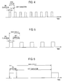
- Fig. 4 to Fig. 6 are diagrams explaining the discontinuous reception.
- the UE 10 In order to reduce power consumption, it is possible for the UE 10 to configure the discontinuous reception.
- a description will be provided for the case where the discontinuous reception is configured in the state in which an RRC connection is established between the UE 10 and the eNB 110 (an RRC connected state).
- a DRX cycle has an On duration, in which a downlink signal transmitted from a serving cell is to be monitored, and an Off duration (Opportunity for DRX) other than the On duration.
- the eNB 110 transmits a dedicated signal addressed to the UE 10 only in an On duration of the UE 10.
- the configuration is such that it suffices to monitor the downlink signal (for example, the PDCCH: Physical Downlink Control Channel), which is transmitted from the eNB 110, only in the On duration, and probably, the UE 10 turns off its own receiver in the Off duration.
- the DRX cycle may include a plurality of types of cycles.
- three DRX cycles (a short DRX cycle, a long DRX cycle, and an extended DRX cycle) will be described.
- the short DRX cycle is a short cycle.
- the length of the short DRX cycle is not particularly limited, and is the order of several milliseconds (for example, 80 msec).
- the short DRX cycle is configured according to a command (DRX command) received from the eNB 110.
- the short DRX cycle is configured when a predetermined period has elapsed after the downlink signal (for example, the PDCCH) is finally received.
- the short DRX cycle is optional, it may not be configured.
- the long DRX cycle is longer than the short DRX cycle.
- the length of the long DRX cycle is not particularly limited, and is the order of several milliseconds (for example, 160 msec).
- a configuration parameter (DRX Config.) is notified from the eNB 110.
- the long DRX cycle is configured when a predetermined period has elapsed after the downlink signal (for example, the PDCCH) is finally received.
- the long DRX cycle is configured when a predetermined period has elapsed after the short DRX cycle is configured.
- the extended DRX cycle is longer than the long DRX cycle.
- the length of the extended DRX cycle is not particularly limited, and is very longer than the short DRX cycle and the long DRX cycle.
- the extended DRX cycle is the order of several seconds.
- the extended DRX cycle is equivalent to a cycle (a Paging Channel Monitoring Cycle), in which a paging signal for notifying that the UE 10 receives an incoming call is monitored, in the state in which the RRC connection has not been established between the UE 10 and the eNB 110 (an RRC idle state).
- the extended DRX cycle is longer than a cycle in which the paging signal for notifying that the UE 10 receives an incoming call is monitored.
- a configuration parameter (DRX Config.) is notified from the eNB 110.
- the extended DRX cycle is configured with the permission of the eNB 110 for a request from the UE 10.
- the extended DRX cycle is configured when a predetermined period has elapsed after the downlink signal (for example, the PDCCH) is finally received.
- the extended DRX cycle is configured when a predetermined period has elapsed after the short DRX cycle or the long DRX cycle is configured.
- the UE 10 may recognize a static configuration parameter in advance, and the extended DRX cycle may also be configured with the permission of the eNB 110 for a request from the UE 10.
- the transition of an RRC state is increased due to an increase in the transmission/reception of a predetermined message. Therefore, since it is estimated that a shortage of a radio resource such as RACH (Random Access Channel) may be caused, the extended DRX cycle is configured in order to suppress the frequent transition of the RRC state in the UE 10 and to suppress the shortage of the network resource.
- the predetermined message includes a message, such as a keep-alive message or a state update message, which is transmitted to a communication correspondent from various applications provided in the UE 10.
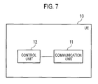
- Fig. 7 is a block diagram illustrating the UE 10 according to the first embodiment. As illustrated in Fig. 7 , the UE 10 includes a communication unit 11 and a control unit 12.
- the communication unit 11 receives a signal from the eNB 110 (or the radio base station 210). Alternatively, the communication unit 11 transmits a signal to the eNB 110 (or the radio base station 210). In addition, the communication unit 11, for example, has an antenna (a plurality of antennas when MIMO is used), a demodulation unit, and a modulation unit.
- the control unit 12 controls the UE 10. For example, when the discontinuous reception (DRX) is configured, the control unit 12 controls the on/off of the communication unit 11. That is, in the On duration in which the downlink signal transmitted from the serving cell is to be monitored, the control unit 12 turns on the communication unit 11 and monitors the downlink signal (for example, the PDCCH) transmitted from the eNB 110. In the Off duration other than the On duration in which the downlink signal transmitted from the serving cell is to be monitored, the control unit 12 turns off the communication unit 11 and does not monitor the downlink signal (for example, the PDCCH) transmitted from the eNB 110.
- the control unit 12 controls the on/off of the communication unit 11. That is, in the On duration in which the downlink signal transmitted from the serving cell is to be monitored, the control unit 12 turns on the communication unit 11 and monitors the downlink signal (for example, the PDCCH) transmitted from the eNB 110.
- the control unit 12 turns off the communication unit 11 and does not monitor the downlink signal (for example, the P
- the control unit 12 monitors the paging signal at a predetermined timing in duration (that is, an Off duration) other than an On duration in which a downlink signal transmitted from a serving cell is to be monitored.
- the predetermined timing may be called PO (Paging Occasion) and includes one or more subframes.
- the control unit 12 since the control unit 12 monitors PDCCH in the On duration of the DRX cycle configured in the RRC connected state, it is of course that it is possible to receive the paging signal.
- the paging signal is not transmitted to the UE 10 in the RRC connected state.
- the eNB 110 transmits the paging signal to the UE 10 at a predetermined timing in the Off duration of the DRX cycle configured in the RRC connected state.
- the control unit 12 may monitor the paging signal in the Off duration. That is, when the short DRX cycle and the long DRX cycle have been configured, the control unit 12 may not monitor the paging signal in the Off duration.
- control unit 12 releases the DRX cycle in response to the reception of the paging signal.
- the control unit 12 may release the DRX cycle and enter a mode for continuously monitoring a downlink signal.
- the control unit 12 may release the DRX cycle (for example, the extended DRX cycle) and configure a DRX cycle (for example, the short DRX cycle and the long DRX cycle) shorter than the DRX cycle.
- the control unit 12 may release the DRX cycle and start a reestablish procedure for the eNB 110.
- Fig. 8 is a sequence diagram illustrating the mobile communication method according to the first embodiment.
- step 10 the UE 10 transmits a connection request (RRC Connection Request) to the eNB 110.
- RRC Connection Request a connection request
- step 20 the eNB 110 transmits a connection setup (RRC Connection Setup) to the UE 10.
- RRC Connection Setup a connection setup
- step 30 the UE 10 transmits a connection complete (RRC Connection Complete) to the eNB 110.
- RRC Connection Complete a connection complete
- step 40 the UE 10 configures DRX.
- the UE 10 configures an extended DRX cycle.
- step 50A to step 50C the UE 10 monitors a paging signal at a predetermined timing in duration (that is, an Off duration) other than an On duration in which a downlink signal transmitted from the serving cell is to be monitored.
- step 60 the UE 10 monitors the downlink signal (for example, PDCCH) in the On duration in which the downlink signal transmitted from the serving cell is to be monitored.
- the downlink signal for example, PDCCH
- step 70 the eNB 110 transmits the paging signal at a predetermined timing in the duration (that is, the Off duration) other than the On duration in which the downlink signal transmitted from the serving cell is to be monitored.
- step 80 the UE 10 monitors the paging signal at a predetermined timing in the On duration in which the downlink signal transmitted from the serving cell is to be monitored. Furthermore, the UE 10 receives the paging signal.
- the UE 10 releases the DRX cycle in response to the reception of the paging signal.
- the UE 10 may release the DRX cycle and enter a mode for continuously monitoring the downlink signal.
- the UE 10 may release the DRX cycle (for example, the extended DRX cycle) and configure a DRX cycle (for example, the short DRX cycle, the long DRX cycle, and continuous reception) shorter than the DRX cycle.
- the UE 10 may release the DRX cycle and start a reestablish procedure for the eNB 110.
- the eNB 110 transmits the paging signal at a predetermined timing in the duration (that is, the Off duration) other than the On duration in which the downlink signal transmitted from the serving cell is to be monitored, and the UE 10 monitors the paging signal at a predetermined timing in the duration (that is, the Off duration) other than the On duration in which the downlink signal transmitted from the serving cell is to be monitored.
- the paging signal is received in the duration (that is, the Off duration) other than the On duration in which the downlink signal transmitted from the serving cell is to be monitored, so that it is possible to perform an incoming-call process.
- an extended DRX cycle having a very long DRX cycle when configured, it is effective to monitor the paging signal at a predetermined timing in the duration (that is, the Off duration) other than the On duration in which the downlink signal transmitted from the serving cell is to be monitored.
- the extended DRX cycle is configured such that frequent transition of the UE 10 to the RRC state is suppressed, preventing a shortage of the network resource will be suppressed.
- the extended DRX cycle is configured such that the power consumption of the UE 10 is reduced.
- the extended DRX cycle is configured such that the power consumption of the UE 10 is reduced.
- the configuration for monitoring the paging signal includes conditions for starting a process for monitoring the paging signal and a monitoring cycle of the paging signal in the duration (that is, the Off duration) other than the On duration in which the downlink signal transmitted from the serving cell is to be monitored.
- the configuration for monitoring the paging signal for example, may be notified to the UE 10 through RRC signaling, or may be notified to the UE 10 through a broadcast channel.
- the broadcast channel is broadcasted from the eNB 110 and transfers MIB (Master Information Block) or SIB (System Information Block).
- a DRX cycle (specifically, an extended DRX cycle)
- a setting request of the DRX cycle is transmitted from the UE 10 to the eNB 110 and setting permission of the DRX cycle is transmitted from the eNB 110 to the UE 10.
- the configuration for monitoring the paging signal is included in the setting permission transmitted from the eNB 110 to the UE 10.
- the PDCCH may be monitored if a monitoring timing of the paging signal overlaps the On duration, and only the paging signal may be monitored if the monitoring timing of the paging signal overlaps the Off duration.
- the present invention can provide the mobile communication method and the radio terminal that can suppress the problem in accordance with prolongation of the Off duration when the DRX cycle such as the extended DRX cycle is configured.
Landscapes
- Engineering & Computer Science (AREA)
- Computer Networks & Wireless Communication (AREA)
- Signal Processing (AREA)
- Mobile Radio Communication Systems (AREA)
Abstract
Description
- The present invention relates to a mobile communication method, which configures a DRX cycle (a discontinuous reception cycle) having an On duration, in which a downlink signal transmitted from a serving cell is to be monitored, and an Off duration other than the On duration, and a radio terminal.
- In the next generation communication system such as LTE (Long Term Evolution), in order to reduce the power consumption of a radio terminal, a technology called DRX (Discontinuous Reception) is employed (for example, NPL 1).
- In the DRX, a DRX cycle has an On duration, in which a downlink signal (for example, PDCCH: Physical Downlink Control Channel) transmitted from a serving cell is to be monitored, and an Off duration (Opportunity for DRX) other than the On duration. A radio base station transmits a dedicated signal addressed to a radio terminal only in an On duration of the radio terminal. As described above, the configuration is such that the radio terminal may monitor the downlink signal transmitted from the radio base station, only in the On duration, and may turn off its own receiver in the Off duration. In addition, the DRX cycle may include two cycles (a short DRX cycle and a long DRX cycle). Furthermore, a DRX mode may be configured in the state in which an RRC connection is established between the radio terminal and the radio base station (RRC connected state). That is, it should be noted that the Off duration of the DRX cycle is different from an RRC idle state. In addition, in the 3GPP standard, the long DRX cycle is mandatory and the short DRX cycle is optional.
- However, in recent years, there have been increased radio terminals having various applications. The application is configured to periodically transmit and receive a predetermined message such as a keep-alive message or a state update message to/from a communication correspondent such as a server. In such a case, , since a control signal is transmitted and received due to the transition toward an RRC state, whenever the predetermined message is transmitted or received, a shortage of a network resource will be caused.
- In this regard, in order to suppress the shortage of the network resource, the provision of a DRX cycle (for example, an extended DRX cycle) longer than the existing DRX cycle (for example, the short DRX cycle and the long DRX cycle) (for example, NPL 2) is under consideration.
-
- NPL 1: TS36.321 V10.0.0
- NPL 1: RP-110454
- However, it is assumed that the length of the extended DRX cycle is several seconds or more and the extended DRX cycle is very long as compared with the short DRX cycle, the long DRX cycle and the like. Therefore, the Off duration of the extended DRX cycle is expected to be very long.
- Therefore, when the extended DRX cycle is configured, various countermeasures are necessary. For example, since it is not possible to perform an incoming-call process in the Off duration, the incoming-call process may be significantly delayed.
- Therefore, the present invention is directed to solve the above mentioned problem. The purpose of the present invention is to provide a mobile communication method and a radio terminal that can suppress the problem in accordance with prolongation of the Off duration when the DRX cycle such as the extended DRX cycle is configured.
- A mobile communication method of a first feature configures a DRX cycle having an On duration in which a downlink signal transmitted from a serving base station is to be monitored and an Off duration other than the On duration in an RRC connected state where an RRC connection is established between a radio terminal and a radio base station. The mobile communication method comprises: a step A of transmitting, from the radio base station to the radio terminal, a paging signal for notifying the radio terminal of an incoming call to the radio terminal at a predetermined timing in the Off duration when the DRX cycle is configured; and a step B of monitoring, at the radio terminal, the paging signal at the predetermined timing in the Off duration when the DRX cycle is configured.
- In the first feature, the mobile communication method according to
claim 1, comprises: a step C of releasing, at the radio terminal, the DRX cycle in response to reception of the paging signal. - In the first feature, the step C comprises: a step of releasing the DRX cycle and monitoring the downlink signal continuously, at the radio terminal.
- In the first feature, the step C comprises: a step of releasing the DRX cycle and configuring a DRX cycle shorter than the DRX cycle, at the radio terminal.
- In the first feature, the step C comprises: a step of starting, at the radio terminal, a reestablish procedure for the radio base station in response to reception of the paging signal.
- A radio terminal of a second feature is configured to receive a downlink signal in a mobile communication system, which configures a DRX cycle having an On duration in which the downlink signal transmitted from a serving base station is to be monitored and an Off duration other than the On duration in an RRC connected state where an RRC connection is established between the radio terminal and a radio base station. The radio terminal comprises: a control unit configured to monitor a paging signal at a predetermined timing in the Off duration when the DRX cycle is configured.
-
- [
Fig. 1] Fig. 1 is a diagram illustrating amobile communication system 100 according to a first embodiment. - [
Fig. 2] Fig. 2 is a diagram illustrating a radio frame according to the first embodiment. - [
Fig. 3] Fig. 3 is a diagram illustrating a radio resource according to the first embodiment. - [
Fig. 4] Fig. 4 is a diagram illustrating a short DRX cycle according to the first embodiment. - [
Fig. 5] Fig. 5 is a diagram illustrating a long DRX cycle according to the first embodiment. - [
Fig. 6] Fig. 6 is a diagram illustrating an extended DRX cycle according to the first embodiment. - [
Fig. 7] Fig. 7 is a block diagram illustrating aUE 10 according to the first embodiment. - [
Fig. 8] Fig. 8 is a sequence diagram illustrating a mobile communication method according to the first embodiment. - A mobile communication system according to an embodiment of the present invention is described below with reference to the drawings. Note that, in the following description of the drawings, same or similar reference signs denote same or similar elements and portions.
- In addition, it should be noted that the drawings are schematic and ratios of dimensions and the like are different from actual ones. Therefore, specific dimensions and the like should be determined in consideration of the following description. Moreover, the drawings also include portions having different dimensional relationships and ratios from each other.
- A mobile communication method of an embodiment configures a DRX cycle having an On duration in which a downlink signal transmitted from a serving base station is to be monitored and an Off duration other than the On duration in an RRC connected state where an RRC connection is established between a radio terminal and a radio base station. The mobile communication method comprises: a step A of transmitting, from the radio base station to the radio terminal, a paging signal for notifying the radio terminal of an incoming call to the radio terminal at a predetermined timing in the Off duration when the DRX cycle is configured; and a step B of monitoring, at the radio terminal, the paging signal at a predetermined timing in the Off duration when the DRX cycle is configured.
- According to the embodiment, when a DRX cycle is configured in an RRC connected state, the radio base station transmits a paging signal at a predetermined timing even in the Off duration, and the radio terminal monitors the paging signal at a predetermined timing in an Off duration of the DRX cycle configured in the RRC connected state.
- Consequently, even when a very long DRX cycle is configured, the paging signal is received in the Off duration, so that it is possible to perform an incoming-call process.
- Hereinafter, a mobile communication system according to a first embodiment will be described.
Fig. 1 is a diagram illustrating themobile communication system 100 according to a first embodiment. - As illustrated in
Fig. 1 , themobile communication system 100 includes a radio terminal 10 (hereinafter, referred to as UE 10) and acore network 50. Furthermore, themobile communication system 100 includes a first communication system and a second communication system. - The first communication system, for example, is an LTE (Long Term Evolution)-compatible communication system. The first communication system, for example, includes a radio base station 110 (hereinafter, referred to as eNB 110) and MME 120. In addition, in the first communication system, a first RAT (EUTRAN; Evolved Universal Terrestrial Access Network) is used.
- The second communication system, for example, is a WCDMA (Wideband Code Division Multiple Access)-compatible communication system. The second communication system, for example, includes a
radio base station 210, RNC 220, and SGSN 230. In addition, in the second communication system, a second RAT (UTRAN; Universal Terrestrial Access Network) is used. - The
UE 10 is a device (User Equipment) configured to communicate with the first communication system and the second communication system. For example, theUE 10 has a function of performing radio communication with theeNB 110, and a function of performing radio communication with theradio base station 210. - The
eNB 110, having acell 111, is a device (evolved NodeB) configured to perform radio communication with theUE 10 existing in thecell 111. - The
MME 120 is a device (Mobility Management Entity) configured to manage the mobility of theUE 10 which establishes a radio connection with theeNB 110. TheMME 120 is provided in thecore network 50. - The
radio base station 210, having acell 211, is a device (NodeB) configured to perform radio communication with theUE 10 existing in thecell 211. - The
RNC 220, connected to theradio base station 210, is a device (Radio Network Controller) configured to establish a radio connection (RRC Connection) with theUE 10 existing in thecell 211. - The
SGSN 230 is a device (Serving GPRS Support Node) configured to perform packet switching in a packet switching domain. TheSGSN 230 is provided in thecore network 50. Although not illustrated inFig. 1 , a device (MSC; Mobile Switching Center) configured to perform circuit switching in a circuit switching domain may be provided in thecore network 50. - Hereinafter, the first communication system will be mainly described. The following description may also be applied to the second communication system. Furthermore, a cell should be understood as a function of performing radio communication with the
UE 10. The cell may also be considered as a service area indicating a range communicable with the cell. - Here, in the first communication system, an OFDMA (Orthogonal Frequency Division Multiple Access) scheme is used as a downlink multiplexing scheme, and an SC-FDMA (Single-Carrier Frequency Division Multiple Access) scheme is used as an uplink multiplexing scheme.
- Furthermore, in the first communication system, an uplink channel includes an uplink control channel (PUCCH; Physical Uplink Control Channel), an uplink shared channel (PUSCH; Physical Uplink Shared Channel), and the like. Furthermore, a downlink channel includes a downlink control channel (PDCCH; Physical Downlink Control Channel), a downlink shared channel (PDSCH; Physical Downlink Shared Channel), and the like.
- The uplink control channel is used to transfer a control signal. The control signal, for example, includes CQI (Channel Quality Indictor), PMI (Precoding Matrix Indicator), RI (Rank Indicator), SR (Scheduling Request), and ACK/NACK.
- The CQI is a signal for notifying a recommended modulation scheme and a coding rate to be used in downlink transmission. The PMI is a signal indicating a precoder matrix which is preferably used in downlink transmission. The RI is a signal indicating the number of layers (streams) to be used in downlink transmission. The SR is a signal for requesting the assignment of an uplink radio resource (a resource block which will be described later). The ACK/NACK is a signal indicating whether a signal transmitted through the downlink channel (for example, the PDSCH) has been successfully received.
- The uplink shared channel is used to transfer a control signal (includes the above-mentioned control signal) and/or a data signal. For example, the uplink radio resource may be assigned only to the data signal, or assigned such that the data signal and the control signal are multiplexed.
- The downlink control channel is used to transfer a control signal. The control signal, for example, includes Uplink SI (Scheduling Information), Downlink SI (Scheduling Information), and a TPC bit.
- The Uplink SI is a signal indicating the assignment of the uplink radio resource. The Downlink SI is a signal indicating the assignment of a downlink radio resource. The TPC bit is a signal for instructing increase or decrease in the power of a signal transmitted through the uplink channel.
- The downlink shared channel is used to transfer a control signal and/or a data signal. For example, the downlink radio resource may be assigned only to the data signal, or assigned such that the data signal and the control signal are multiplexed.
- In addition, a control signal transmitted through the downlink shared channel includes TA (Timing Advance). The TA is transmission timing correction information between the
UE 10 and theeNB 110, and is measured by theeNB 110 based on an uplink signal transmitted from theUE 10. - Furthermore, a control signal transmitted through a channel, other than the downlink control channel (the PDCCH) and the downlink shared channel (the PDSCH), includes ACK/NACK. The ACK/NACK is a signal indicating whether a signal transmitted through the uplink channel (for example, the PUSCH) has been successfully received.
- Hereinafter, a radio frame in the first communication system will be described.
Fig. 2 is a diagram illustrating the radio frame in the first communication system. - As illustrated in
Fig. 2 , one radio frame includes 10 subframes and one subframe includes two slots. One slot has a time length of 0.5 msec, one subframe has a time length of 1 msec, and one radio frame has a time length of 10 msec. - In addition, one slot includes a plurality of OFDM symbols (for example, six OFDM symbols or seven OFDM symbols) in the downward direction. In the same manner, one slot includes a plurality of SC-FDMA symbols (for example, six SC-FDMA symbols or seven SC-FDMA symbols) in the upward direction.
- Hereinafter, a radio resource in the first communication system will be described.
Fig. 3 is a diagram illustrating the radio resource in the first communication system. - As illustrated in
Fig. 3 , a radio resource is defined by a frequency axis and a time axis. A frequency includes a plurality of subcarriers, and a predetermined number of subcarriers (12 subcarriers) are collectively called a resource block (RB). A time has a unit, such as the OFDM symbol (or the SC-FDMA symbol), the slot, the subframe, or the radio frame, as described above. - Here, the radio resource is assignable to each resource block. Furthermore, on the frequency axis and the time axis, it is possible to divide the radio resources to assign the same to a plurality of users (for example,
user # 1 to user #5). - Furthermore, the radio resource is assigned by the
eNB 110. TheeNB 110 assigns the radio resource to eachUE 10 based on the CQI, the PMI, the RI and the like. - Hereinafter, a discontinuous reception (DRX) will be described.
Fig. 4 to Fig. 6 are diagrams explaining the discontinuous reception. In order to reduce power consumption, it is possible for theUE 10 to configure the discontinuous reception. Hereinafter, a description will be provided for the case where the discontinuous reception is configured in the state in which an RRC connection is established between theUE 10 and the eNB 110 (an RRC connected state). - As illustrated in
Fig. 4 to Fig. 6 , according to the discontinuous reception (DRX), a DRX cycle has an On duration, in which a downlink signal transmitted from a serving cell is to be monitored, and an Off duration (Opportunity for DRX) other than the On duration. TheeNB 110 transmits a dedicated signal addressed to theUE 10 only in an On duration of theUE 10. As described above, the configuration is such that it suffices to monitor the downlink signal (for example, the PDCCH: Physical Downlink Control Channel), which is transmitted from theeNB 110, only in the On duration, and probably, theUE 10 turns off its own receiver in the Off duration. - In addition, the DRX cycle may include a plurality of types of cycles. Hereinafter, three DRX cycles (a short DRX cycle, a long DRX cycle, and an extended DRX cycle) will be described.
- As illustrated in
Fig. 4 , the short DRX cycle is a short cycle. The length of the short DRX cycle is not particularly limited, and is the order of several milliseconds (for example, 80 msec). - For example, the short DRX cycle is configured according to a command (DRX command) received from the
eNB 110. Alternatively, the short DRX cycle is configured when a predetermined period has elapsed after the downlink signal (for example, the PDCCH) is finally received. In addition, since the short DRX cycle is optional, it may not be configured. - As illustrated in
Fig. 5 , the long DRX cycle is longer than the short DRX cycle. The length of the long DRX cycle is not particularly limited, and is the order of several milliseconds (for example, 160 msec). - For example, when the long DRX cycle is configured, a configuration parameter (DRX Config.) is notified from the
eNB 110. The long DRX cycle is configured when a predetermined period has elapsed after the downlink signal (for example, the PDCCH) is finally received. Alternatively, the long DRX cycle is configured when a predetermined period has elapsed after the short DRX cycle is configured. - As illustrated in
Fig. 6 , the extended DRX cycle is longer than the long DRX cycle. The length of the extended DRX cycle is not particularly limited, and is very longer than the short DRX cycle and the long DRX cycle. For example, the extended DRX cycle is the order of several seconds. For example, the extended DRX cycle is equivalent to a cycle (a Paging Channel Monitoring Cycle), in which a paging signal for notifying that theUE 10 receives an incoming call is monitored, in the state in which the RRC connection has not been established between theUE 10 and the eNB 110 (an RRC idle state). Alternatively, in the RRC idle state, the extended DRX cycle is longer than a cycle in which the paging signal for notifying that theUE 10 receives an incoming call is monitored. - For example, when the extended DRX cycle is configured, a configuration parameter (DRX Config.) is notified from the
eNB 110. The extended DRX cycle is configured with the permission of theeNB 110 for a request from theUE 10. Alternatively, the extended DRX cycle is configured when a predetermined period has elapsed after the downlink signal (for example, the PDCCH) is finally received. Alternatively, the extended DRX cycle is configured when a predetermined period has elapsed after the short DRX cycle or the long DRX cycle is configured. Furthermore, in other examples, theUE 10 may recognize a static configuration parameter in advance, and the extended DRX cycle may also be configured with the permission of theeNB 110 for a request from theUE 10. - In addition, with an increase in the number of
UEs 10 having various applications, the transition of an RRC state is increased due to an increase in the transmission/reception of a predetermined message. Therefore, since it is estimated that a shortage of a radio resource such as RACH (Random Access Channel) may be caused, the extended DRX cycle is configured in order to suppress the frequent transition of the RRC state in theUE 10 and to suppress the shortage of the network resource. In addition, the predetermined message includes a message, such as a keep-alive message or a state update message, which is transmitted to a communication correspondent from various applications provided in theUE 10. - Hereinafter, a radio terminal in the first embodiment will be described.
Fig. 7 is a block diagram illustrating theUE 10 according to the first embodiment. As illustrated inFig. 7 , theUE 10 includes acommunication unit 11 and acontrol unit 12. - The
communication unit 11 receives a signal from the eNB 110 (or the radio base station 210). Alternatively, thecommunication unit 11 transmits a signal to the eNB 110 (or the radio base station 210). In addition, thecommunication unit 11, for example, has an antenna (a plurality of antennas when MIMO is used), a demodulation unit, and a modulation unit. - The
control unit 12 controls theUE 10. For example, when the discontinuous reception (DRX) is configured, thecontrol unit 12 controls the on/off of thecommunication unit 11. That is, in the On duration in which the downlink signal transmitted from the serving cell is to be monitored, thecontrol unit 12 turns on thecommunication unit 11 and monitors the downlink signal (for example, the PDCCH) transmitted from theeNB 110. In the Off duration other than the On duration in which the downlink signal transmitted from the serving cell is to be monitored, thecontrol unit 12 turns off thecommunication unit 11 and does not monitor the downlink signal (for example, the PDCCH) transmitted from theeNB 110. - Specifically, when the DRX cycle is configured in the RRC connected state, the
control unit 12 monitors the paging signal at a predetermined timing in duration (that is, an Off duration) other than an On duration in which a downlink signal transmitted from a serving cell is to be monitored. In addition, the predetermined timing may be called PO (Paging Occasion) and includes one or more subframes. In addition, since thecontrol unit 12 monitors PDCCH in the On duration of the DRX cycle configured in the RRC connected state, it is of course that it is possible to receive the paging signal. - In addition, in the conventional technology, it should be noted that the paging signal is not transmitted to the
UE 10 in the RRC connected state. In the first embodiment, it should be noted that theeNB 110 transmits the paging signal to theUE 10 at a predetermined timing in the Off duration of the DRX cycle configured in the RRC connected state. - Here, only when the extended DRX cycle is configured, the
control unit 12 may monitor the paging signal in the Off duration. That is, when the short DRX cycle and the long DRX cycle have been configured, thecontrol unit 12 may not monitor the paging signal in the Off duration. - Furthermore, the
control unit 12 releases the DRX cycle in response to the reception of the paging signal. For example, thecontrol unit 12 may release the DRX cycle and enter a mode for continuously monitoring a downlink signal. Alternatively, thecontrol unit 12 may release the DRX cycle (for example, the extended DRX cycle) and configure a DRX cycle (for example, the short DRX cycle and the long DRX cycle) shorter than the DRX cycle. Alternatively, thecontrol unit 12 may release the DRX cycle and start a reestablish procedure for theeNB 110. - Hereinafter, the mobile communication method according to the first embodiment will be described.
Fig. 8 is a sequence diagram illustrating the mobile communication method according to the first embodiment. - As illustrated in
Fig. 8 , instep 10, theUE 10 transmits a connection request (RRC Connection Request) to theeNB 110. - In step 20, the
eNB 110 transmits a connection setup (RRC Connection Setup) to theUE 10. - In
step 30, theUE 10 transmits a connection complete (RRC Connection Complete) to theeNB 110. - In step 40, the
UE 10 configures DRX. For example, theUE 10 configures an extended DRX cycle. - In step 50A to step 50C, the
UE 10 monitors a paging signal at a predetermined timing in duration (that is, an Off duration) other than an On duration in which a downlink signal transmitted from the serving cell is to be monitored. - In step 60, the
UE 10 monitors the downlink signal (for example, PDCCH) in the On duration in which the downlink signal transmitted from the serving cell is to be monitored. - In
step 70, theeNB 110 transmits the paging signal at a predetermined timing in the duration (that is, the Off duration) other than the On duration in which the downlink signal transmitted from the serving cell is to be monitored. - In step 80, the
UE 10 monitors the paging signal at a predetermined timing in the On duration in which the downlink signal transmitted from the serving cell is to be monitored. Furthermore, theUE 10 receives the paging signal. - In
step 90, theUE 10 releases the DRX cycle in response to the reception of the paging signal. For example, theUE 10 may release the DRX cycle and enter a mode for continuously monitoring the downlink signal. Alternatively, theUE 10 may release the DRX cycle (for example, the extended DRX cycle) and configure a DRX cycle (for example, the short DRX cycle, the long DRX cycle, and continuous reception) shorter than the DRX cycle. Alternatively, theUE 10 may release the DRX cycle and start a reestablish procedure for theeNB 110. - According to the embodiment, the
eNB 110 transmits the paging signal at a predetermined timing in the duration (that is, the Off duration) other than the On duration in which the downlink signal transmitted from the serving cell is to be monitored, and theUE 10 monitors the paging signal at a predetermined timing in the duration (that is, the Off duration) other than the On duration in which the downlink signal transmitted from the serving cell is to be monitored. - Consequently, even when a very long DRX cycle is configured, the paging signal is received in the duration (that is, the Off duration) other than the On duration in which the downlink signal transmitted from the serving cell is to be monitored, so that it is possible to perform an incoming-call process.
- Specifically, when an extended DRX cycle having a very long DRX cycle is configured, it is effective to monitor the paging signal at a predetermined timing in the duration (that is, the Off duration) other than the On duration in which the downlink signal transmitted from the serving cell is to be monitored.
- As described above, when the frequency of transmission/reception of a predetermined message is lower than a cycle (a Paging Channel Monitoring Cycle) in which the paging signal is monitored in an RRC idle state, the extended DRX cycle is configured such that frequent transition of the
UE 10 to the RRC state is suppressed, preventing a shortage of the network resource will be suppressed. - The present invention is explained through the above embodiment, but it must not be understood that this invention is limited by the statements and the drawings constituting a part of this disclosure. From this disclosure, a variety of alternate embodiments, examples, and applicable techniques will become apparent to one skilled in the art.
- For example, when the frequency of transmission/reception of a predetermined message is lower than a cycle (a Paging Channel Monitoring Cycle) for monitoring the paging signal in an RRC idle state, the extended DRX cycle is configured such that the power consumption of the
UE 10 is reduced. Alternatively, when power consumption, which is required in the On duration in which the downlink signal transmitted from the serving cell is to be monitored, is higher than power consumption required for monitoring the paging signal, the extended DRX cycle is configured such that the power consumption of theUE 10 is reduced. - Particularly not mentioned in the embodiment, but a configuration (Configuration) for monitoring the paging signal in the duration (that is, the Off duration) other than the On duration, in which the downlink signal transmitted from the serving cell is to be monitored, is transmitted from the
eNB 110 to theUE 10 before the DRX cycle is configured. The configuration for monitoring the paging signal, for example, includes conditions for starting a process for monitoring the paging signal and a monitoring cycle of the paging signal in the duration (that is, the Off duration) other than the On duration in which the downlink signal transmitted from the serving cell is to be monitored. The configuration for monitoring the paging signal, for example, may be notified to theUE 10 through RRC signaling, or may be notified to theUE 10 through a broadcast channel. The broadcast channel is broadcasted from theeNB 110 and transfers MIB (Master Information Block) or SIB (System Information Block). - As an example, when a DRX cycle (specifically, an extended DRX cycle) is configured, there is considered a case in which a setting request of the DRX cycle is transmitted from the
UE 10 to theeNB 110 and setting permission of the DRX cycle is transmitted from theeNB 110 to theUE 10. In such a case, it is considered that the configuration for monitoring the paging signal is included in the setting permission transmitted from theeNB 110 to theUE 10. - Particularly not mentioned in the embodiment, but, when the extended DRX cycle includes a cycle (a Paging Channel Monitoring Cycle) for monitoring the paging signal, the PDCCH may be monitored if a monitoring timing of the paging signal overlaps the On duration, and only the paging signal may be monitored if the monitoring timing of the paging signal overlaps the Off duration.
- In addition, in order to receive the paging signal, it is necessary to receive a dedicated PDCCH. However, in the embodiment, the reception of such a dedicated PDCCH will be omitted.
- The present invention can provide the mobile communication method and the radio terminal that can suppress the problem in accordance with prolongation of the Off duration when the DRX cycle such as the extended DRX cycle is configured.
Claims (6)
- A mobile communication method, which configures a DRX cycle having an On duration in which a downlink signal transmitted from a serving base station is to be monitored and an Off duration other than the On duration in an RRC connected state where an RRC connection is established between a radio terminal and a radio base station, the mobile communication method comprising:a step A of transmitting, from the radio base station to the radio terminal, a paging signal for notifying the radio terminal of an incoming call to the radio terminal at a predetermined timing in the Off duration when the DRX cycle is configured; anda step B of monitoring, at the radio terminal, the paging signal at the predetermined timing in the Off duration when the DRX cycle is configured.
- The mobile communication method according to claim 1, comprising:a step C of releasing, at the radio terminal, the DRX cycle in response to reception of the paging signal.
- The mobile communication method according to claim 1, wherein the step C comprises: a step of releasing the DRX cycle and monitoring the downlink signal continuously, at the radio terminal.
- The mobile communication method according to claim 1, wherein the step C comprises: a step of releasing the DRX cycle and configuring a DRX cycle shorter than the DRX cycle, at the radio terminal.
- The mobile communication method according to claim 1, wherein the step C comprises: a step of starting, at the radio terminal, a reestablish procedure for the radio base station in response to reception of the paging signal.
- A radio terminal configured to receive a downlink signal in a mobile communication system, which configures a DRX cycle having an On duration in which the downlink signal transmitted from a serving base station is to be monitored and an Off duration other than the On duration in an RRC connected state where an RRC connection is established between the radio terminal and a radio base station, the radio terminal comprising:a control unit configured to monitor a paging signal at a predetermined timing in the Off duration when the DRX cycle is configured.
Applications Claiming Priority (1)
| Application Number | Priority Date | Filing Date | Title |
|---|---|---|---|
| PCT/JP2011/058564 WO2012137296A1 (en) | 2011-04-04 | 2011-04-04 | Mobile communication method and wireless terminal |
Publications (2)
| Publication Number | Publication Date |
|---|---|
| EP2696629A1 true EP2696629A1 (en) | 2014-02-12 |
| EP2696629A4 EP2696629A4 (en) | 2014-10-22 |
Family
ID=46968737
Family Applications (1)
| Application Number | Title | Priority Date | Filing Date |
|---|---|---|---|
| EP11863072.2A Withdrawn EP2696629A4 (en) | 2011-04-04 | 2011-04-04 | MOBILE COMMUNICATION METHOD AND WIRELESS TERMINAL |
Country Status (5)
| Country | Link |
|---|---|
| EP (1) | EP2696629A4 (en) |
| JP (1) | JP5786022B2 (en) |
| KR (1) | KR20140003590A (en) |
| CN (1) | CN103460765A (en) |
| WO (1) | WO2012137296A1 (en) |
Cited By (3)
| Publication number | Priority date | Publication date | Assignee | Title |
|---|---|---|---|---|
| WO2014178030A1 (en) * | 2013-05-03 | 2014-11-06 | Telefonaktiebolaget L M Ericsson (Publ) | Improved paging for longer paging cycles |
| DE102015121948A1 (en) * | 2015-12-16 | 2017-06-22 | Intel IP Corporation | User equipment for discontinuous reception and procedure performed by a user equipment |
| US9900928B2 (en) | 2013-04-05 | 2018-02-20 | Telefonaktiebolaget Lm Ericsson (Publ) | User equipment, network node, and methods for managing an extended discontinuous reception cycle mode |
Families Citing this family (7)
| Publication number | Priority date | Publication date | Assignee | Title |
|---|---|---|---|---|
| EP2869648B1 (en) | 2013-10-31 | 2020-07-08 | Alcatel Lucent | Responding to paging requests while waiting to request a connection to a wireless network |
| JP2016123037A (en) * | 2014-12-25 | 2016-07-07 | 京セラ株式会社 | Radio communication device, and operation method for radio communication device |
| JPWO2016140275A1 (en) * | 2015-03-03 | 2017-12-14 | 京セラ株式会社 | Mobile communication method, network device, and base station |
| JP6670294B2 (en) * | 2015-03-03 | 2020-03-18 | 京セラ株式会社 | Network device and base station |
| US20200037247A1 (en) * | 2018-07-25 | 2020-01-30 | Mediatek Inc. | Wake-up signal operation for ue power saving |
| WO2022030022A1 (en) * | 2020-08-07 | 2022-02-10 | 株式会社Nttドコモ | Terminal and communication method |
| CN116074932A (en) * | 2021-11-04 | 2023-05-05 | 华为技术有限公司 | A communication method and communication device |
Family Cites Families (16)
| Publication number | Priority date | Publication date | Assignee | Title |
|---|---|---|---|---|
| JPH10135893A (en) * | 1996-10-30 | 1998-05-22 | Mitsubishi Electric Corp | Intermittent reception method and cellular telephone |
| JP2001086553A (en) * | 1999-09-10 | 2001-03-30 | Munehiro Kimoto | Mobile communication system, mobile communication network and mobile terminal used by this mobile communication system |
| RU2389159C1 (en) * | 2006-04-11 | 2010-05-10 | Самсунг Электроникс Ко., Лтд. | Method and device for discontinous packet reception in mobile communication system |
| US7760676B2 (en) * | 2006-06-20 | 2010-07-20 | Intel Corporation | Adaptive DRX cycle length based on available battery power |
| KR101312876B1 (en) * | 2006-12-13 | 2013-09-30 | 삼성전자주식회사 | Method and apparatus for measurementing in a wireless system |
| US8169957B2 (en) * | 2007-02-05 | 2012-05-01 | Qualcomm Incorporated | Flexible DTX and DRX in a wireless communication system |
| JP4624369B2 (en) * | 2007-02-26 | 2011-02-02 | Necインフロンティア株式会社 | Wireless communication control method and method |
| JP5058629B2 (en) * | 2007-02-27 | 2012-10-24 | 京セラ株式会社 | Wireless communication method, wireless communication system, and wireless communication device |
| US8285346B2 (en) * | 2007-05-23 | 2012-10-09 | Telefonaktiebolaget Lm Ericsson (Publ) | Method and arrangement for reducing battery power consumption of a user equipment |
| RU2441342C2 (en) * | 2007-07-05 | 2012-01-27 | Мицубиси Электрик Корпорейшн | Mobile communication system and mobile terminal |
| WO2009088496A1 (en) * | 2008-01-04 | 2009-07-16 | Nokia Siemens Networks Oy | System and method for efficient half duplex transceiver operation in a packet-based wireless communication system |
| EP2146527B1 (en) * | 2008-07-16 | 2011-10-26 | TELEFONAKTIEBOLAGET LM ERICSSON (publ) | Method for multimedia broadcast and multicast service, MBMS, notification indicator detection, computer program, and user equipment apparatus |
| WO2010078365A1 (en) * | 2008-12-30 | 2010-07-08 | Interdigital Patent Holdings, Inc. | Discontinuous reception for carrier aggregation |
| WO2010126409A1 (en) * | 2009-04-27 | 2010-11-04 | Telefonaktiebolaget Lm Ericsson (Publ) | Notifying user equipment of an upcoming change of system information in a radio communication network |
| US8462736B2 (en) * | 2009-06-19 | 2013-06-11 | Telefonaktiebolaget L M Ericsson (Publ) | Telecommunications method and apparatus for facilitating positioning measurements |
| JP2010226746A (en) * | 2010-05-12 | 2010-10-07 | Ntt Docomo Inc | Mobile station |
-
2011
- 2011-04-04 WO PCT/JP2011/058564 patent/WO2012137296A1/en not_active Ceased
- 2011-04-04 CN CN2011800697922A patent/CN103460765A/en active Pending
- 2011-04-04 JP JP2013508658A patent/JP5786022B2/en not_active Expired - Fee Related
- 2011-04-04 EP EP11863072.2A patent/EP2696629A4/en not_active Withdrawn
- 2011-04-04 KR KR1020137026842A patent/KR20140003590A/en not_active Ceased
Cited By (7)
| Publication number | Priority date | Publication date | Assignee | Title |
|---|---|---|---|---|
| US9900928B2 (en) | 2013-04-05 | 2018-02-20 | Telefonaktiebolaget Lm Ericsson (Publ) | User equipment, network node, and methods for managing an extended discontinuous reception cycle mode |
| WO2014178030A1 (en) * | 2013-05-03 | 2014-11-06 | Telefonaktiebolaget L M Ericsson (Publ) | Improved paging for longer paging cycles |
| US9451587B2 (en) | 2013-05-03 | 2016-09-20 | Telefonaktiebolaget Lm Ericsson (Publ) | Paging for longer paging cycles |
| US10362558B2 (en) | 2013-05-03 | 2019-07-23 | Telefonaktiebolaget Lm Ericsson (Publ) | Paging for longer paging cycles |
| DE102015121948A1 (en) * | 2015-12-16 | 2017-06-22 | Intel IP Corporation | User equipment for discontinuous reception and procedure performed by a user equipment |
| US10292201B2 (en) | 2015-12-16 | 2019-05-14 | Intel IP Corporation | User equipment for discontinuous reception and method performed by a user equipment |
| DE102015121948B4 (en) | 2015-12-16 | 2021-10-28 | Intel Corporation | User equipment for discontinuous reception and procedure performed by user equipment |
Also Published As
| Publication number | Publication date |
|---|---|
| JPWO2012137296A1 (en) | 2014-07-28 |
| JP5786022B2 (en) | 2015-09-30 |
| EP2696629A4 (en) | 2014-10-22 |
| KR20140003590A (en) | 2014-01-09 |
| CN103460765A (en) | 2013-12-18 |
| WO2012137296A1 (en) | 2012-10-11 |
Similar Documents
| Publication | Publication Date | Title |
|---|---|---|
| US9204392B2 (en) | Mobile communication method and radio terminal | |
| US10104613B2 (en) | Mobile communication method and radio terminal | |
| US8837313B2 (en) | Mobile communication method and radio terminal | |
| EP3522615B1 (en) | Mobile communication method and radio terminal | |
| EP2696629A1 (en) | Mobile communication method and wireless terminal | |
| EP2696630A1 (en) | Mobile communication method and wireless terminal | |
| US9749987B2 (en) | Mobile communication method and radio base station | |
| US20160205628A1 (en) | Mobile communication method, radio terminal, and radio base station | |
| US11284471B2 (en) | Prioritizing network access | |
| JP6010666B2 (en) | Communication control method and radio base station | |
| JP2015046884A (en) | Mobile communication method and radio base station | |
| JP5627808B2 (en) | Wireless terminal and apparatus | |
| HK40020828A (en) | Uplink channel quality measurement using a subframe with high-intensity reference signal bursts | |
| HK40020828B (en) | Uplink channel quality measurement using a subframe with high-intensity reference signal bursts |
Legal Events
| Date | Code | Title | Description |
|---|---|---|---|
| PUAI | Public reference made under article 153(3) epc to a published international application that has entered the european phase |
Free format text: ORIGINAL CODE: 0009012 |
|
| 17P | Request for examination filed |
Effective date: 20131023 |
|
| AK | Designated contracting states |
Kind code of ref document: A1 Designated state(s): AL AT BE BG CH CY CZ DE DK EE ES FI FR GB GR HR HU IE IS IT LI LT LU LV MC MK MT NL NO PL PT RO RS SE SI SK SM TR |
|
| DAX | Request for extension of the european patent (deleted) | ||
| A4 | Supplementary search report drawn up and despatched |
Effective date: 20140919 |
|
| RIC1 | Information provided on ipc code assigned before grant |
Ipc: H04W 76/04 20090101ALI20140915BHEP Ipc: H04W 68/02 20090101ALI20140915BHEP Ipc: H04W 52/02 20090101AFI20140915BHEP Ipc: H04W 24/10 20090101ALI20140915BHEP Ipc: H04W 84/02 20090101ALI20140915BHEP |
|
| 17Q | First examination report despatched |
Effective date: 20170922 |
|
| STAA | Information on the status of an ep patent application or granted ep patent |
Free format text: STATUS: THE APPLICATION IS DEEMED TO BE WITHDRAWN |
|
| 18D | Application deemed to be withdrawn |
Effective date: 20180203 |