EP2696609A2 - Electronic device and control device - Google Patents
Electronic device and control device Download PDFInfo
- Publication number
- EP2696609A2 EP2696609A2 EP13178226.0A EP13178226A EP2696609A2 EP 2696609 A2 EP2696609 A2 EP 2696609A2 EP 13178226 A EP13178226 A EP 13178226A EP 2696609 A2 EP2696609 A2 EP 2696609A2
- Authority
- EP
- European Patent Office
- Prior art keywords
- electronic device
- pairing
- electronic devices
- control device
- pairing information
- Prior art date
- Legal status (The legal status is an assumption and is not a legal conclusion. Google has not performed a legal analysis and makes no representation as to the accuracy of the status listed.)
- Withdrawn
Links
Images


Classifications
-
- H—ELECTRICITY
- H04—ELECTRIC COMMUNICATION TECHNIQUE
- H04W—WIRELESS COMMUNICATION NETWORKS
- H04W76/00—Connection management
- H04W76/10—Connection setup
- H04W76/15—Setup of multiple wireless link connections
- H04W76/16—Involving different core network technologies, e.g. a packet-switched [PS] bearer in combination with a circuit-switched [CS] bearer
-
- H—ELECTRICITY
- H04—ELECTRIC COMMUNICATION TECHNIQUE
- H04W—WIRELESS COMMUNICATION NETWORKS
- H04W8/00—Network data management
- H04W8/005—Discovery of network devices, e.g. terminals
-
- H—ELECTRICITY
- H04—ELECTRIC COMMUNICATION TECHNIQUE
- H04W—WIRELESS COMMUNICATION NETWORKS
- H04W76/00—Connection management
- H04W76/10—Connection setup
- H04W76/14—Direct-mode setup
Definitions
- the present invention relates to an electronic device and a control device, e.g., to an electronic device that is connected to another electronic device by a wireless network and a control device that controls the electronic device.
- a wireless network such as a wireless LAN (Local Area Network) and ZigBee
- a wireless network such as a wireless LAN (Local Area Network) and ZigBee
- the electronic devices can transmit and receive data via the wireless network, cables for transmitting and receiving the data may not be placed. Movement of the electronic devices is easy.
- pairing such as sharing of a secret key for encryption and/or setting of addresses
- pairing information including addresses is delivered between the electronic devices.
- Performing delivery of the pairing information between the electronic devices through a remote control is known.
- Infrared data communication is used for transmission and reception of the pairing information between the remote control and the electronic device (e.g. see Patent Documents 1 and 2).
- a main electronic device performs setting of the pairing information, and transmits the pairing information to the remote control. Therefore, the main electronic device has a function for setting and transmitting the pairing information. The size of the main electronic device is enlarged, and the power consumption of the main electronic device becomes large. After the pairing information is transmitted to each electronic device, a pairing button of each electronic device needs to be pushed in order to begin the pairing.
- a control device (10) disclosed herein includes: an acquisition portion (20) configured to acquire, from an information processing apparatus (16), pairing information corresponding to at least one of electronic devices (12, 14) among from a plurality of pieces of pairing information corresponding to the respective electronic devices, the pairing information being used in order that the electronic devices (12, 14) connected to each other via a wireless network (17) perform pairing; and an output portion (24) configured to output the pairing information corresponding to the at least one of the electronic devices to the at least one of the electronic devices by using a non-contact system (15) different from the wireless network. According to the control device, it is possible to reduce the size of the electronic device.
- a control device (10) disclosed herein includes: an output portion (24) configured to output a trigger signal to at least one of electronic devices (12, 14) by using a non-contact system (15) different from a wireless network (17), the trigger signal being used in order that the electronic devices connected to each other via the wireless network begin pairing. According to the control device, it is possible to simplify the beginning of the pairing.
- FIG. 1 is a block diagram illustrating a system including electronic devices and a control device according to a first embodiment.
- a system 100 includes a control device 10, sub electronic devices 12, a main electronic device 14, and an information processing apparatus 16.
- the main electronic device 14 and the sub electronic devices 12 are connected to each other via a wireless network 17.
- a wireless network 17 is a wireless LAN (Local Area Network) (e.g. IEEE802.11) or a ZigBee.
- the control device 10 outputs the pairing information to the main electronic device 14 and the sub electronic devices 12 by using a non-contact system 15 which is a system different from the wireless network 17.
- the non-contact system 15 is an infrared data communication system, such as IrDA (Infrared Data Association), or a wireless system, such as RFID (Radio Frequency Identification), for example.
- the information processing apparatus 16 is a personal computer, a mobile phone, a smart phone or the like.
- An exclusive application is installed in the information processing apparatus 16, and sets the pairing information on each of the electronic devices 12 and 14.
- the pairing information is information for setting connection as a network between the electronic devices 12 and 14, and includes addresses, passwords, and/or a radio channel of each of the electronic devices 12 and 14.
- the sub electronic device 12 is a power strip, for example.
- the sub electronic device 12 measures power consumption, and transmits power supply information including the measured power consumption to the main electronic device 14 via the wireless network 17.
- the main electronic device 14 is a management device for each power strip, for example.
- the main electronic device 14 manages power supply information of each power strip, and transmits and receives information to/from an external device via a network 18.
- the power strip is often installed in a place that does not usually stand out, such as a place under a desk or under a roof.
- the main electronic device 14 transmits and receives the information to/from the sub electronic devices 12 via the wireless network 17, so that the power supply information can be easily managed.
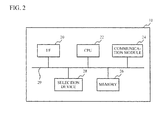
- FIG. 2 is a block diagram of the control device.
- the control device 10 includes an interface (I/F) 20, a CPU (Central Processing Unit) 22, a communication module 24, a memory 26, a selection device 28, and a bus 29.
- the interface 20 acquires the pairing information from the information processing apparatus 16.
- the CPU 22 controls the interface 20, the communication module 24, the memory 26, and the selection device 28 via the bus 29.
- the communication module 24 outputs the pairing information to the electronic devices 12 and 14.
- the memory 26 stores the pairing information corresponding to each of the electronic devices 12 and 14.
- the selection device 28 selects at least one of the electronic devices 12 and 14 to which the pairing information is output.
- FIG. 3 is a block diagram of the electronic device.
- each of the electronic devices 12 and 14 includes a communication module 30, a CPU 32, a memory 36, a main function device 34, and a wireless module 38.
- the communication module 30 acquires the pairing information from the control device 10.
- the CPU 32 controls the communication module 30, the memory 36, the main function device 34, and the wireless module 38 via a bus 39.
- the memory 36 stores the pairing information and so on.
- the main function device 34 performs main functions of the electronic device.
- the main function device 34 is a power strip.
- the main function device 34 is a computer that manages the power supply information.
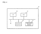
- FIG. 4 is a block diagram of the information processing apparatus.
- the information processing apparatus 16 includes an interface (I/F) 40, a CPU 42, a memory 46, and an input and output device 44.
- the interface 40 outputs the pairing information to the control device 10.
- the CPU 42 controls the interface 40, the CPU 42, the memory 46, and the input and output device 44 via a bus 49.
- the memory 46 stores the pairing information corresponding to each of the electronic devices 12 and 14.
- Each of the interface 20 of the control device 10 and the interface 40 of the information processing apparatus 16 is a reader and writer for RFID (Radio Frequency IDentification), an IrDA (Infrared Data Association) transmitting and receiving device, an interface for RS232C or USB (Universal Serial Bus), or a reader and writer for a SD (Secure Digital) card or CF (Compact Flash) storage card, for example.
- RFID Radio Frequency IDentification
- IrDA Infrared Data Association
- RS232C or USB Universal Serial Bus
- SD Secure Digital
- CF Compact Flash
- FIG. 5 is a sequence diagram of each device.
- the information processing apparatus 16 acquires information on the electronic devices 12 and 14 (step S10).
- the information on the electronic devices 12 and 14 is acquired from the control device 10 via the interface 40 or the input and output device 44, for example.
- the information processing apparatus 16 generates a plurality of pieces of pairing information corresponding to the electronic devices 12 and 14 based on the information on the electronic devices 12 and 14 (step S12).
- the plurality of pieces of generated pairing information are stored into the memory 46.
- the wireless network 17 is first built, for example, the information processing apparatus 16 generates the plurality of pieces of pairing information corresponding to all of the electronic devices 12 and 14.
- the sub electronic device 12 is newly added to wireless network 17, the information processing apparatus 16 generates pairing information corresponding to the sub electronic device 12 to be newly added.
- the interface 40 of the information processing apparatus 16 transmits the pairing information to the interface 20 of the control device 10 (step S14).
- the communication module 24 of the control device 10 transmits the pairing information to the main electronic device 14 (step S16).
- the communication module 24 of the control device 10 transmits the pairing information on the sub electronic device 12 to the main electronic device 14.
- the communication module 24 of the control device 10 transmits the pairing information to the sub electronic device 12 (step S18).
- the communication module 24 of the control device 10 transmits the pairing information on the main electronic device 14 to the sub electronic device 12.
- the main electronic device 14 and the sub electronic device 12 communicate with each other via the wireless network 17 by using the wireless module 38 (step S20).
- FIG. 6 is a flowchart illustrating a process of the control device.
- the CPU 22 causes the interface 20 to acquire the pairing information from the information processing apparatus 16 (step S30).
- the CPU 22 associates the pairing information with the electronic devices 12 and 14, and stores the associated pairing information into the memory 26 (step S32).
- the CPU 22 receives information on the electronic device 12 or 14 for transmitting the pairing information, from the selection device 28.
- the selection device 28 is a selection button, a touch panel, or a selection dial, for example.
- a user moves the control device 10 in the vicinity of the electronic device 12 or 14.
- the user selects the electronic device 12 or 14 for transmitting the pairing information by using the selection device 28 (step S34).
- the selection device 28 may automatically select the electronic device.
- the CPU 22 reads out the pairing information corresponding to the selected electronic device 12 or 14 from the memory 26 (step S36).
- the CPU 22 causes the communication module 24 to transmit the pairing information to the selected electronic device 12 or 14 (step S38).
- the CPU 22 judges whether the transmission of the pairing information on all of the electronic device 12 or 14 which performs the pairing has been completed (step S40). When the answer to the judgment is YES, the process is terminated. When the answer to the judgment is NO, the process proceeds to step S32.
- the control device 10 transmits the pairing information on the main electronic device 14 to all of the sub electronic devices 12.
- the control device 10 transmits the pairing information on all of the sub electronic devices 12 to the main electronic device 14.
- the control device 10 transmits the pairing information corresponding to the sub electronic device 12 to be newly added, to the main electronic device 14.
- the control device 10 transmits the pairing information on the main electronic device 14 to the sub electronic device 12 to be newly added.
- step S16 of FIG. 5 is omitted.
- the control device 10 does not transmit the pairing information corresponding to the main electronic device 14 to the sub electronic device 12, but transmits the pairing information on the sub electronic device 12 to the main electronic device 14.
- step S18 of FIG. 5 is omitted.
- the interface 20 of the control device 10 acquires, from the information processing apparatus, the pairing information corresponding to at least one of the electronic devices 12 and 14 among from the plurality of pieces of pairing information corresponding to the respective electronic devices 12 and 14.
- the communication module 24 (an output portion) outputs the pairing information corresponding to the at least one of the electronic devices 12 and 14 to the at least one of the electronic devices 12 and 14 by using the non-contact system 15 different from the wireless network 17.
- the main electronic device 14 does not need to generate the pairing information. Therefore, logic and memories for generating the pairing information can be reduced.
- the wireless module 30 of the main electronic device 14 does not need to transmit information to the control device 10. Therefore, the main electronic device 14 does not need to use a transmission unit, for example. Thus, the main electronic device 14 can be downsized.
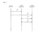
- FIG. 7 is a sequence diagram of each device according to the second embodiment.
- the communication module 24 of the control device 10 transmits a trigger signal to the main electronic device 14 (step S50).
- the communication module 24 of the control device 10 transmits a trigger signal to the sub electronic device 12 (step S52).
- the main electronic device 14 and the sub electronic device 12 receive the trigger signals, respectively, the main electronic device 14 and the sub electronic device 12 perform the pairing (step S54).
- the pairing is completed, the main electronic device 14 and the sub electronic device 12 communicate with each other via the wireless network 17 (step S56).
- FIG. 8 is a flowchart illustrating a process of the electronic device.
- the CPU 32 in the electronic device judges whether the communication module 30 has received the trigger signal from the control device 10 (step S60). When the answer to the judgment is NO, the process returns to step S60.
- the CPU 32 performs the pairing with another electronic device (e.g. the main electronic device) to be paired (step S62). The pairing is performed using the wireless network 17, for example. Then, the CPU 32 communicates with the another electronic device via the wireless module 38 (step S64).
- the communication module 24 of the control device 10 outputs the trigger signal for beginning the pairing to at least one of the electronic devices.
- the communication module 30 (a receiving portion) of the electronic device 12 or 14 receives the trigger signal from the control device 10.
- the CPU 32 a pairing portion
- the CPU 32 begins the pairing with another electronic device.
- the trigger signal is outputted by using the non-contact system 15 which is a system different from the infrared data communication system such as IrDA, or the wireless network 17 such as RFID.
- the user does not need to go to the electronic device in order to depress the button for the pairing. Therefore, even when the power strip is attached to an inconspicuous place such as a place under the roof, the pairing can be performed easily.
- the power strip is explained as the sub electronic device 12, and the management device of the power supply information is explained as the main electronic device 14.
- Each of the main electronic device 14 and the sub electronic device 12 may be an electronic device connected via a wireless network system for performing the pairing. Although an example of a star-type network using the main electronic device 14 and the sub electronic devices 12 is explained as the wireless network 17, another network system may be used. Moreover, the number of each of electronic devices 14 and 12 may be two or more.
Landscapes
- Engineering & Computer Science (AREA)
- Computer Networks & Wireless Communication (AREA)
- Signal Processing (AREA)
- Databases & Information Systems (AREA)
- Selective Calling Equipment (AREA)
- Mobile Radio Communication Systems (AREA)
Abstract
Description
- The present invention relates to an electronic device and a control device, e.g., to an electronic device that is connected to another electronic device by a wireless network and a control device that controls the electronic device.
- Electronic devices which are connected to each other by a wireless network, such as a wireless LAN (Local Area Network) and ZigBee, are used. Since the electronic devices can transmit and receive data via the wireless network, cables for transmitting and receiving the data may not be placed. Movement of the electronic devices is easy. In order to connect the electronic devices to the wireless network, pairing, such as sharing of a secret key for encryption and/or setting of addresses, is performed between the electronic devices. For the pairing, pairing information including addresses is delivered between the electronic devices. Performing delivery of the pairing information between the electronic devices through a remote control is known. Infrared data communication is used for transmission and reception of the pairing information between the remote control and the electronic device (e.g. see Patent Documents 1 and 2).
-
- Patent Document 1: Japanese National Publication of International Patent Application No.
2006-526933 - Patent Document 2: Japanese Laid-open Patent Publication No.
2004-200887 - However, in the above-mentioned method, a main electronic device performs setting of the pairing information, and transmits the pairing information to the remote control. Therefore, the main electronic device has a function for setting and transmitting the pairing information. The size of the main electronic device is enlarged, and the power consumption of the main electronic device becomes large. After the pairing information is transmitted to each electronic device, a pairing button of each electronic device needs to be pushed in order to begin the pairing.
- It is an object of the present invention to provide an electronic device that can simplify the beginning of the pairing, and a control device that can reduce the size of the electronic device or simplify the beginning of the pairing.
- A control device (10) disclosed herein includes: an acquisition portion (20) configured to acquire, from an information processing apparatus (16), pairing information corresponding to at least one of electronic devices (12, 14) among from a plurality of pieces of pairing information corresponding to the respective electronic devices, the pairing information being used in order that the electronic devices (12, 14) connected to each other via a wireless network (17) perform pairing; and an output portion (24) configured to output the pairing information corresponding to the at least one of the electronic devices to the at least one of the electronic devices by using a non-contact system (15) different from the wireless network. According to the control device, it is possible to reduce the size of the electronic device.
- A control device (10) disclosed herein includes: an output portion (24) configured to output a trigger signal to at least one of electronic devices (12, 14) by using a non-contact system (15) different from a wireless network (17), the trigger signal being used in order that the electronic devices connected to each other via the wireless network begin pairing. According to the control device, it is possible to simplify the beginning of the pairing.
- An electronic device (12, 14) disclosed herein connected to another electronic device (12, 14) via a wireless network (17), includes: a reception portion (30) configured to receive a trigger signal for beginning pairing with the another electronic device, from a control device (10) by using a non-contact system (15) different from the wireless network; and a pairing portion (32) configured to begin pairing with the another electronic device when the trigger signal is received. According to the electronic device, it is possible to simplify the beginning of the pairing.
- According to the present invention, it is possible to reduce the size of an electronic device or simplify the beginning of the pairing.
-
-
FIG. 1 is a block diagram illustrating a system including electronic devices and a control device according to a first embodiment; -
FIG. 2 is a block diagram of the control device; -
FIG. 3 is a block diagram of the electronic device; -
FIG. 4 is a block diagram of an information processing apparatus; -
FIG. 5 is a sequence diagram of each device; -
FIG. 6 is a flowchart illustrating a process of the control device; -
FIG. 7 is a sequence diagram of each device according to a second embodiment; and -
FIG. 8 is a flowchart illustrating a process of the electronic device. - Hereinafter, a description will be given of embodiments of the present invention with reference to the drawings.
-
FIG. 1 is a block diagram illustrating a system including electronic devices and a control device according to a first embodiment. As illustrated inFIG. 1 , asystem 100 includes acontrol device 10, subelectronic devices 12, a mainelectronic device 14, and aninformation processing apparatus 16. The mainelectronic device 14 and the subelectronic devices 12 are connected to each other via awireless network 17. Thus, a plurality of electronic devices are connected to each other via the wireless network. The mainelectronic device 14 is connected to an external network such as Ethernet. Thewireless network 17 is a wireless LAN (Local Area Network) (e.g. IEEE802.11) or a ZigBee. - The
control device 10 outputs the pairing information to the mainelectronic device 14 and the subelectronic devices 12 by using anon-contact system 15 which is a system different from thewireless network 17. Thenon-contact system 15 is an infrared data communication system, such as IrDA (Infrared Data Association), or a wireless system, such as RFID (Radio Frequency Identification), for example. - The
information processing apparatus 16 is a personal computer, a mobile phone, a smart phone or the like. An exclusive application is installed in theinformation processing apparatus 16, and sets the pairing information on each of theelectronic devices electronic devices electronic devices - The sub
electronic device 12 is a power strip, for example. The subelectronic device 12 measures power consumption, and transmits power supply information including the measured power consumption to the mainelectronic device 14 via thewireless network 17. The mainelectronic device 14 is a management device for each power strip, for example. The mainelectronic device 14 manages power supply information of each power strip, and transmits and receives information to/from an external device via anetwork 18. The power strip is often installed in a place that does not usually stand out, such as a place under a desk or under a roof. The mainelectronic device 14 transmits and receives the information to/from the subelectronic devices 12 via thewireless network 17, so that the power supply information can be easily managed. -
FIG. 2 is a block diagram of the control device. As illustrated inFIG. 2 , thecontrol device 10 includes an interface (I/F) 20, a CPU (Central Processing Unit) 22, acommunication module 24, amemory 26, aselection device 28, and abus 29. Theinterface 20 acquires the pairing information from theinformation processing apparatus 16. TheCPU 22 controls theinterface 20, thecommunication module 24, thememory 26, and theselection device 28 via thebus 29. Thecommunication module 24 outputs the pairing information to theelectronic devices memory 26 stores the pairing information corresponding to each of theelectronic devices selection device 28 selects at least one of theelectronic devices -
FIG. 3 is a block diagram of the electronic device. As illustrated inFIG. 3 , each of theelectronic devices communication module 30, aCPU 32, amemory 36, amain function device 34, and awireless module 38. Thecommunication module 30 acquires the pairing information from thecontrol device 10. TheCPU 32 controls thecommunication module 30, thememory 36, themain function device 34, and thewireless module 38 via abus 39. Thememory 36 stores the pairing information and so on. Themain function device 34 performs main functions of the electronic device. When an electronic device is the subelectronic device 12, for example, themain function device 34 is a power strip. When an electronic device is the mainelectronic device 14, themain function device 34 is a computer that manages the power supply information. -
FIG. 4 is a block diagram of the information processing apparatus. As illustrated inFIG. 4 , theinformation processing apparatus 16 includes an interface (I/F) 40, aCPU 42, amemory 46, and an input andoutput device 44. Theinterface 40 outputs the pairing information to thecontrol device 10. TheCPU 42 controls theinterface 40, theCPU 42, thememory 46, and the input andoutput device 44 via abus 49. Thememory 46 stores the pairing information corresponding to each of theelectronic devices - Each of the
interface 20 of thecontrol device 10 and theinterface 40 of theinformation processing apparatus 16 is a reader and writer for RFID (Radio Frequency IDentification), an IrDA (Infrared Data Association) transmitting and receiving device, an interface for RS232C or USB (Universal Serial Bus), or a reader and writer for a SD (Secure Digital) card or CF (Compact Flash) storage card, for example. Thus, a wireless system such as the IrDA or the RFID, a wire system such as the RS232C or the USB, or a storage medium such as the SD card or the CF card can be used for the transmission of the pairing information from theinformation processing apparatus 16 to thecontrol device 10. -
FIG. 5 is a sequence diagram of each device. As illustrated inFIG. 5 , theinformation processing apparatus 16 acquires information on theelectronic devices 12 and 14 (step S10). The information on theelectronic devices control device 10 via theinterface 40 or the input andoutput device 44, for example. Next, theinformation processing apparatus 16 generates a plurality of pieces of pairing information corresponding to theelectronic devices electronic devices 12 and 14 (step S12). The plurality of pieces of generated pairing information are stored into thememory 46. When thewireless network 17 is first built, for example, theinformation processing apparatus 16 generates the plurality of pieces of pairing information corresponding to all of theelectronic devices electronic device 12 is newly added towireless network 17, theinformation processing apparatus 16 generates pairing information corresponding to the subelectronic device 12 to be newly added. - Next, the
interface 40 of theinformation processing apparatus 16 transmits the pairing information to theinterface 20 of the control device 10 (step S14). Thecommunication module 24 of thecontrol device 10 transmits the pairing information to the main electronic device 14 (step S16). For example, thecommunication module 24 of thecontrol device 10 transmits the pairing information on the subelectronic device 12 to the mainelectronic device 14. Next, thecommunication module 24 of thecontrol device 10 transmits the pairing information to the sub electronic device 12 (step S18). For example, thecommunication module 24 of thecontrol device 10 transmits the pairing information on the mainelectronic device 14 to the subelectronic device 12. Thereby, the pairing between the mainelectronic device 14 and the subelectronic device 12 is completed. Then, the mainelectronic device 14 and the subelectronic device 12 communicate with each other via thewireless network 17 by using the wireless module 38 (step S20). -
FIG. 6 is a flowchart illustrating a process of the control device. As illustrated inFIG. 6 , theCPU 22 causes theinterface 20 to acquire the pairing information from the information processing apparatus 16 (step S30). TheCPU 22 associates the pairing information with theelectronic devices CPU 22 receives information on theelectronic device selection device 28. Theselection device 28 is a selection button, a touch panel, or a selection dial, for example. A user moves thecontrol device 10 in the vicinity of theelectronic device electronic device selection device 28 may automatically select the electronic device. - The
CPU 22 reads out the pairing information corresponding to the selectedelectronic device CPU 22 causes thecommunication module 24 to transmit the pairing information to the selectedelectronic device 12 or 14 (step S38). TheCPU 22 judges whether the transmission of the pairing information on all of theelectronic device - For example, when the
wireless network 17 is first built, for example, thecontrol device 10 transmits the pairing information on the mainelectronic device 14 to all of the subelectronic devices 12. Thecontrol device 10 transmits the pairing information on all of the subelectronic devices 12 to the mainelectronic device 14. When the subelectronic device 12 is newly added towireless network 17, thecontrol device 10 transmits the pairing information corresponding to the subelectronic device 12 to be newly added, to the mainelectronic device 14. Thecontrol device 10 transmits the pairing information on the mainelectronic device 14 to the subelectronic device 12 to be newly added. For example, when the mainelectronic device 14 includes the pairing information corresponding to the subelectronic device 12 in advance, thecontrol device 10 does not transmit the pairing information corresponding to the subelectronic device 12 to the mainelectronic device 14, but transmits the pairing information on the mainelectronic device 14 to the subelectronic device 12. In this case, step S16 ofFIG. 5 is omitted. For example, when the subelectronic device 12 includes the pairing information corresponding to the mainelectronic device 14 in advance, thecontrol device 10 does not transmit the pairing information corresponding to the mainelectronic device 14 to the subelectronic device 12, but transmits the pairing information on the subelectronic device 12 to the mainelectronic device 14. In this case, step S18 ofFIG. 5 is omitted. - According to the first embodiment, as illustrated in step S30 of
FIG. 6 , theinterface 20 of the control device 10 (an acquisition portion) acquires, from the information processing apparatus, the pairing information corresponding to at least one of theelectronic devices electronic devices electronic devices electronic devices non-contact system 15 different from thewireless network 17. Thereby, the mainelectronic device 14 does not need to generate the pairing information. Therefore, logic and memories for generating the pairing information can be reduced. Thewireless module 30 of the mainelectronic device 14 does not need to transmit information to thecontrol device 10. Therefore, the mainelectronic device 14 does not need to use a transmission unit, for example. Thus, the mainelectronic device 14 can be downsized. - The block diagrams of the system and each device according to a second embodiment are the same as those of the first embodiment, and hence a description thereof is omitted. Here, the system of the second embodiment does not need to be provided with the
information processing apparatus 16. Thecontrol unit 10 does not need to be provided with theinterface 20.FIG. 7 is a sequence diagram of each device according to the second embodiment. As illustrated inFIG. 7 , thecommunication module 24 of thecontrol device 10 transmits a trigger signal to the main electronic device 14 (step S50). Thecommunication module 24 of thecontrol device 10 transmits a trigger signal to the sub electronic device 12 (step S52). When the mainelectronic device 14 and the subelectronic device 12 receive the trigger signals, respectively, the mainelectronic device 14 and the subelectronic device 12 perform the pairing (step S54). When the pairing is completed, the mainelectronic device 14 and the subelectronic device 12 communicate with each other via the wireless network 17 (step S56). -
FIG. 8 is a flowchart illustrating a process of the electronic device. As illustrated inFIG. 8 , theCPU 32 in the electronic device judges whether thecommunication module 30 has received the trigger signal from the control device 10 (step S60). When the answer to the judgment is NO, the process returns to step S60. When the answer to the judgment is YES, theCPU 32 performs the pairing with another electronic device (e.g. the main electronic device) to be paired (step S62). The pairing is performed using thewireless network 17, for example. Then, theCPU 32 communicates with the another electronic device via the wireless module 38 (step S64). - According to the second embodiment, as illustrated in steps S50 and S52 of
FIG. 7 , thecommunication module 24 of thecontrol device 10 outputs the trigger signal for beginning the pairing to at least one of the electronic devices. The communication module 30 (a receiving portion) of theelectronic device control device 10. When the CPU 32 (a pairing portion) has received the trigger signal, theCPU 32 begins the pairing with another electronic device. The trigger signal is outputted by using thenon-contact system 15 which is a system different from the infrared data communication system such as IrDA, or thewireless network 17 such as RFID. Thereby, the user does not need to go to the electronic device in order to depress the button for the pairing. Therefore, even when the power strip is attached to an inconspicuous place such as a place under the roof, the pairing can be performed easily. - In the first and the second embodiments, the power strip is explained as the sub
electronic device 12, and the management device of the power supply information is explained as the mainelectronic device 14. Each of the mainelectronic device 14 and the subelectronic device 12 may be an electronic device connected via a wireless network system for performing the pairing. Although an example of a star-type network using the mainelectronic device 14 and the subelectronic devices 12 is explained as thewireless network 17, another network system may be used. Moreover, the number of each ofelectronic devices - Although the embodiments of the present invention is described in detail, the present invention is not limited to the specifically described embodiments and variations but other embodiments and variations may be made without departing from the scope of the claimed invention.
Claims (7)
- A control device (10) characterized by comprising:an acquisition portion (20) configured to acquire, from an information processing apparatus (16), pairing information corresponding to at least one of electronic devices (12, 14) among from a plurality of pieces of pairing information corresponding to the respective electronic devices, the pairing information being used in order that the electronic devices (12, 14) connected to each other via a wireless network (17) perform pairing; andan output portion (24) configured to output the pairing information corresponding to the at least one of the electronic devices to the at least one of the electronic devices by using a non-contact system (15) different from the wireless network.
- The control device as claimed in claim 1, characterized in that the output portion (24) outputs the pairing information to the at least one of the electronic devices by using infrared data communication.
- The control device as claimed in claim 1 or 2, characterized in that the acquisition portion (20) acquires the pairing information corresponding to the at least one of the electronic devices from the information processing apparatus by using any one of a wireless system, a wire system and a storage medium.
- The control device as claimed in any one of claims 1 to 3, characterized by further comprising:a selection portion (28) configured to select an electronic device to which the pairing information is transmitted, from the electronic devices.
- A control device (10) comprising:an output portion (24) configured to output a trigger signal to at least one of electronic devices (12, 14) by using a non-contact system (15) different from a wireless network (17), the trigger signal being used in order that the electronic devices connected to each other via the wireless network begin pairing.
- The control device as claimed in claim 5, wherein the output portion outputs the trigger signal to the at least one of the electronic devices by using infrared data communication.
- An electronic device (12, 14) connected to another electronic device (12, 14) via a wireless network (17), characterized by comprising:a reception portion (30) configured to receive a trigger signal for beginning pairing with the another electronic device, from a control device (10) by using a non-contact system (15) different from the wireless network; anda pairing portion (32) configured to begin pairing with the another electronic device when the trigger signal is received.
Applications Claiming Priority (1)
| Application Number | Priority Date | Filing Date | Title |
|---|---|---|---|
| JP2012177391A JP5985299B2 (en) | 2012-08-09 | 2012-08-09 | Electronic device, control device and network system |
Publications (2)
| Publication Number | Publication Date |
|---|---|
| EP2696609A2 true EP2696609A2 (en) | 2014-02-12 |
| EP2696609A3 EP2696609A3 (en) | 2016-06-29 |
Family
ID=48900805
Family Applications (1)
| Application Number | Title | Priority Date | Filing Date |
|---|---|---|---|
| EP13178226.0A Withdrawn EP2696609A3 (en) | 2012-08-09 | 2013-07-26 | Electronic device and control device |
Country Status (3)
| Country | Link |
|---|---|
| US (1) | US9554412B2 (en) |
| EP (1) | EP2696609A3 (en) |
| JP (1) | JP5985299B2 (en) |
Cited By (2)
| Publication number | Priority date | Publication date | Assignee | Title |
|---|---|---|---|---|
| EP3010365A4 (en) * | 2014-06-12 | 2017-03-01 | Que Products, LLC | Audio-visual system for multi-compartment traveling |
| EP3220662A1 (en) * | 2016-03-15 | 2017-09-20 | Oticon A/s | An audio assist system for pairing between a hearing aid and audio system |
Families Citing this family (4)
| Publication number | Priority date | Publication date | Assignee | Title |
|---|---|---|---|---|
| KR102216451B1 (en) * | 2014-10-01 | 2021-02-17 | 삼성전자주식회사 | Display apparatus, system and method for display apparatus |
| US20160174272A1 (en) * | 2014-12-16 | 2016-06-16 | Qualcomm Incorporated | Method and system for automating and assisting wi-fi direct connections using mobile-device ir-blaster |
| JP6447920B2 (en) * | 2015-04-10 | 2019-01-09 | パナソニックIpマネジメント株式会社 | Lighting fixture, lighting system, and control method thereof |
| US11533764B2 (en) * | 2018-03-09 | 2022-12-20 | Stryker Corporation | Systems and methods for remotely controlling a surgical instrument of console-based surgical systems |
Citations (2)
| Publication number | Priority date | Publication date | Assignee | Title |
|---|---|---|---|---|
| JP2004200887A (en) | 2002-12-17 | 2004-07-15 | Hitachi Software Eng Co Ltd | Wireless communication apparatus designating method and system |
| JP2006526933A (en) | 2003-06-04 | 2006-11-24 | 松下電器産業株式会社 | Management device, communication device, mediation device, communication device registration method, program, and integrated circuit for registering communication device in wireless network |
Family Cites Families (20)
| Publication number | Priority date | Publication date | Assignee | Title |
|---|---|---|---|---|
| US20030013440A1 (en) * | 2001-03-30 | 2003-01-16 | Sunao Takatori | Wireless lan system and control method and control program of wireless lan system |
| US20040071471A1 (en) * | 2002-10-10 | 2004-04-15 | Interlink Electronics, Inc. | Method and system for pairing a remote control transmitter and receiver |
| US8959187B2 (en) * | 2004-02-23 | 2015-02-17 | Apple Inc. | Method and system for proximity-based information retrieval and exchange in ad hoc networks |
| JP4405309B2 (en) * | 2004-04-07 | 2010-01-27 | 株式会社バッファロー | Access point, wireless LAN connection method, medium recording wireless LAN connection program, and wireless LAN system |
| US20050278462A1 (en) * | 2004-06-14 | 2005-12-15 | Gillespie Vandy L | Wireless home entertainment interconnection and control system and method |
| US8611536B2 (en) * | 2004-09-08 | 2013-12-17 | Qualcomm Incorporated | Bootstrapping authentication using distinguished random challenges |
| US7860038B2 (en) * | 2006-08-04 | 2010-12-28 | Microsoft Corporation | Wireless support for portable media player devices |
| JP4902857B2 (en) * | 2006-12-18 | 2012-03-21 | 三菱電機株式会社 | Communication system, communication terminal, communication method, and communication program |
| DE102007007345A1 (en) * | 2007-02-14 | 2008-08-21 | Siemens Enterprise Communications Gmbh & Co. Kg | Method and device for providing a wireless mesh network |
| US20090067363A1 (en) * | 2007-07-31 | 2009-03-12 | Johnson Controls Technology Company | System and method for communicating information from wireless sources to locations within a building |
| US8947199B2 (en) * | 2008-06-11 | 2015-02-03 | Freescale Semiconductor, Inc. | Method and apparatus for enabling communication between a first device and at least one further device |
| US8736427B2 (en) * | 2008-09-03 | 2014-05-27 | Apple Inc. | Intelligent infrared remote pairing |
| CN101930660A (en) * | 2009-06-25 | 2010-12-29 | 骏升科技(扬州)有限公司 | RF remote control device capable of remotely controlling multiple kinds of IR equipment and remote control method thereof |
| US8907768B2 (en) * | 2009-11-25 | 2014-12-09 | Visa International Service Association | Access using a mobile device with an accelerometer |
| WO2012063187A1 (en) | 2010-11-10 | 2012-05-18 | Koninklijke Philips Electronics N.V. | A method of pairing communicating devices using a linking device |
| US8671311B2 (en) * | 2011-02-15 | 2014-03-11 | International Business Machines Corporation | Multiprocessor switch with selective pairing |
| KR101851532B1 (en) * | 2011-11-23 | 2018-06-11 | 삼성전자주식회사 | Termianl apparatus, remote control apparatus and method for auto pairing thereof |
| US8869240B2 (en) * | 2011-11-28 | 2014-10-21 | Xerox Corporation | Soft method for local secure connection to a device |
| JP5963528B2 (en) * | 2012-05-07 | 2016-08-03 | キヤノン株式会社 | COMMUNICATION DEVICE AND ITS CONTROL METHOD |
| US9900091B2 (en) * | 2014-06-24 | 2018-02-20 | Samsung Electronics Co., Ltd. | Method and apparatus for pairing electronic device and lighting device |
-
2012
- 2012-08-09 JP JP2012177391A patent/JP5985299B2/en not_active Expired - Fee Related
-
2013
- 2013-07-10 US US13/938,464 patent/US9554412B2/en not_active Expired - Fee Related
- 2013-07-26 EP EP13178226.0A patent/EP2696609A3/en not_active Withdrawn
Patent Citations (2)
| Publication number | Priority date | Publication date | Assignee | Title |
|---|---|---|---|---|
| JP2004200887A (en) | 2002-12-17 | 2004-07-15 | Hitachi Software Eng Co Ltd | Wireless communication apparatus designating method and system |
| JP2006526933A (en) | 2003-06-04 | 2006-11-24 | 松下電器産業株式会社 | Management device, communication device, mediation device, communication device registration method, program, and integrated circuit for registering communication device in wireless network |
Cited By (4)
| Publication number | Priority date | Publication date | Assignee | Title |
|---|---|---|---|---|
| EP3010365A4 (en) * | 2014-06-12 | 2017-03-01 | Que Products, LLC | Audio-visual system for multi-compartment traveling |
| EP3220662A1 (en) * | 2016-03-15 | 2017-09-20 | Oticon A/s | An audio assist system for pairing between a hearing aid and audio system |
| CN107277694A (en) * | 2016-03-15 | 2017-10-20 | 奥迪康有限公司 | For the audio accessory system matched between audiphone and audio system |
| US10206050B2 (en) | 2016-03-15 | 2019-02-12 | Oticon A/S | Audio assist system for pairing between a hearing aid and audio system |
Also Published As
| Publication number | Publication date |
|---|---|
| US20140044435A1 (en) | 2014-02-13 |
| US9554412B2 (en) | 2017-01-24 |
| JP2014036376A (en) | 2014-02-24 |
| EP2696609A3 (en) | 2016-06-29 |
| JP5985299B2 (en) | 2016-09-06 |
Similar Documents
| Publication | Publication Date | Title |
|---|---|---|
| EP2696609A2 (en) | Electronic device and control device | |
| CN110032344B (en) | Communication apparatus, control method thereof, and computer-readable recording medium | |
| CN103489304A (en) | Transfer equipment, transfer processing system and method | |
| CN109257071B (en) | Equipment control method, device and equipment | |
| CN102710420B (en) | The method of password, system and equipment thereof are set | |
| CN102421164B (en) | Radio communication apparatus and control method thereof | |
| CN104378145A (en) | Pairing method and system of Bluetooth device | |
| KR20150114765A (en) | Image forming apparatus supporting function of NFC(near field communication) and method for setting NFC operation mode thereof | |
| US20130185769A1 (en) | Near field communication electronic device, login system using the same and method thereof | |
| CN103763786A (en) | Equipment pairing method, terminal and system | |
| CN104123766A (en) | Access control system using near field communication | |
| CN105393471A (en) | A system and method for transmitting, storing receiving and/or retrieving identification information or data and/or pairing information or data between accessories or associated products and smart electronic devices into and/or from any distinct server or storage media | |
| CN103246838A (en) | External device of mobile terminal | |
| CN103646521B (en) | A kind of wireless remote controller to code method and its system | |
| CN106411865A (en) | Data transmission method and device, and terminal | |
| CN107006066B (en) | Communication device, control method of communication device, and program | |
| CN101587633A (en) | Wireless device, wireless control system and wireless control method | |
| JP2012134872A (en) | Card type electronic device, communication terminal and authentication method | |
| US20170077974A1 (en) | Wearable terminal mountable on part of body of user | |
| US9655152B2 (en) | Operating environment setting system of electronic device, operating environment setting method and operating environment setting program | |
| EP2874465A1 (en) | Method and system for remote equipment data installation | |
| CN204089848U (en) | A kind of television teaching system based on NFC | |
| US9779036B2 (en) | Communication device, information processing method, and program | |
| US20130210348A1 (en) | Apparatus and method for providing near field communication for mobile device | |
| CN111465096A (en) | Wireless positioning method, device and storage medium |
Legal Events
| Date | Code | Title | Description |
|---|---|---|---|
| AK | Designated contracting states |
Kind code of ref document: A2 Designated state(s): AL AT BE BG CH CY CZ DE DK EE ES FI FR GB GR HR HU IE IS IT LI LT LU LV MC MK MT NL NO PL PT RO RS SE SI SK SM TR |
|
| AX | Request for extension of the european patent |
Extension state: BA ME |
|
| PUAI | Public reference made under article 153(3) epc to a published international application that has entered the european phase |
Free format text: ORIGINAL CODE: 0009012 |
|
| PUAL | Search report despatched |
Free format text: ORIGINAL CODE: 0009013 |
|
| AK | Designated contracting states |
Kind code of ref document: A3 Designated state(s): AL AT BE BG CH CY CZ DE DK EE ES FI FR GB GR HR HU IE IS IT LI LT LU LV MC MK MT NL NO PL PT RO RS SE SI SK SM TR |
|
| AX | Request for extension of the european patent |
Extension state: BA ME |
|
| RIC1 | Information provided on ipc code assigned before grant |
Ipc: H04W 8/00 20090101AFI20160525BHEP Ipc: H04W 76/02 20090101ALI20160525BHEP |
|
| 17P | Request for examination filed |
Effective date: 20160802 |
|
| RBV | Designated contracting states (corrected) |
Designated state(s): AL AT BE BG CH CY CZ DE DK EE ES FI FR GB GR HR HU IE IS IT LI LT LU LV MC MK MT NL NO PL PT RO RS SE SI SK SM TR |
|
| GRAP | Despatch of communication of intention to grant a patent |
Free format text: ORIGINAL CODE: EPIDOSNIGR1 |
|
| STAA | Information on the status of an ep patent application or granted ep patent |
Free format text: STATUS: GRANT OF PATENT IS INTENDED |
|
| RIC1 | Information provided on ipc code assigned before grant |
Ipc: H04W 8/00 20090101AFI20180907BHEP Ipc: H04W 76/14 20180101ALI20180907BHEP |
|
| INTG | Intention to grant announced |
Effective date: 20180924 |
|
| STAA | Information on the status of an ep patent application or granted ep patent |
Free format text: STATUS: THE APPLICATION IS DEEMED TO BE WITHDRAWN |
|
| 18D | Application deemed to be withdrawn |
Effective date: 20190205 |