EP2696461A2 - Electromechanical apparatus and electrical switching apparatus employing electronic circuit to condition motor input power - Google Patents
Electromechanical apparatus and electrical switching apparatus employing electronic circuit to condition motor input power Download PDFInfo
- Publication number
- EP2696461A2 EP2696461A2 EP13175331.1A EP13175331A EP2696461A2 EP 2696461 A2 EP2696461 A2 EP 2696461A2 EP 13175331 A EP13175331 A EP 13175331A EP 2696461 A2 EP2696461 A2 EP 2696461A2
- Authority
- EP
- European Patent Office
- Prior art keywords
- motor
- structured
- input
- voltage
- filter
- Prior art date
- Legal status (The legal status is an assumption and is not a legal conclusion. Google has not performed a legal analysis and makes no representation as to the accuracy of the status listed.)
- Granted
Links
- 230000007246 mechanism Effects 0.000 claims abstract description 19
- 239000004020 conductor Substances 0.000 description 5
- 238000010586 diagram Methods 0.000 description 3
- 230000006872 improvement Effects 0.000 description 2
- 238000004519 manufacturing process Methods 0.000 description 2
- 230000001052 transient effect Effects 0.000 description 2
- 230000000712 assembly Effects 0.000 description 1
- 238000000429 assembly Methods 0.000 description 1
- 230000007423 decrease Effects 0.000 description 1
- 230000007547 defect Effects 0.000 description 1
- 238000001514 detection method Methods 0.000 description 1
- 230000000694 effects Effects 0.000 description 1
- 238000009413 insulation Methods 0.000 description 1
- 238000000034 method Methods 0.000 description 1
- 238000012986 modification Methods 0.000 description 1
- 230000004048 modification Effects 0.000 description 1
- 230000004044 response Effects 0.000 description 1
Images

Classifications
-
- H—ELECTRICITY
- H02—GENERATION; CONVERSION OR DISTRIBUTION OF ELECTRIC POWER
- H02H—EMERGENCY PROTECTIVE CIRCUIT ARRANGEMENTS
- H02H3/00—Emergency protective circuit arrangements for automatic disconnection directly responsive to an undesired change from normal electric working condition with or without subsequent reconnection ; integrated protection
- H02H3/26—Emergency protective circuit arrangements for automatic disconnection directly responsive to an undesired change from normal electric working condition with or without subsequent reconnection ; integrated protection responsive to difference between voltages or between currents; responsive to phase angle between voltages or between currents
-
- H—ELECTRICITY
- H02—GENERATION; CONVERSION OR DISTRIBUTION OF ELECTRIC POWER
- H02H—EMERGENCY PROTECTIVE CIRCUIT ARRANGEMENTS
- H02H7/00—Emergency protective circuit arrangements specially adapted for specific types of electric machines or apparatus or for sectionalised protection of cable or line systems, and effecting automatic switching in the event of an undesired change from normal working conditions
- H02H7/08—Emergency protective circuit arrangements specially adapted for specific types of electric machines or apparatus or for sectionalised protection of cable or line systems, and effecting automatic switching in the event of an undesired change from normal working conditions for dynamo-electric motors
-
- H—ELECTRICITY
- H02—GENERATION; CONVERSION OR DISTRIBUTION OF ELECTRIC POWER
- H02H—EMERGENCY PROTECTIVE CIRCUIT ARRANGEMENTS
- H02H9/00—Emergency protective circuit arrangements for limiting excess current or voltage without disconnection
- H02H9/005—Emergency protective circuit arrangements for limiting excess current or voltage without disconnection avoiding undesired transient conditions
Definitions
- the disclosed concept pertains generally to electromechanical apparatus and, more particularly, to electromechanical apparatus including a motor.
- the disclosed concept further pertains to electrical switching apparatus including a motor.
- An electrical switching apparatus typically includes at least one bus assembly having separable contacts, and an operating mechanism.
- the separable contacts include a fixed contact and a movable contact. Each contact is coupled to, and in electrical communication with, a conductive bus that is further coupled to, and in electrical communication with, a line or a load.
- the electrical switching apparatus is a circuit interrupter, then it typically includes a trip device structured to detect an overcurrent condition and to actuate the operating mechanism.
- the operating mechanism is structured to both open the contacts, either manually or following actuation by the trip device, and close the contacts.
- the operating mechanism includes both a closing assembly having a number of closing springs and an opening assembly having a number of opening springs. These assemblies may have common elements that are structured to move the movable contact between a first, open position, wherein the separable contacts are separated, and a second, closed position, wherein the separable contacts are coupled and in electrical communication.
- the operating mechanism may also include a rotatable pole shaft that is coupled to the movable contact and structured to move each movable contact between the closed position and the open position. Elements of both the closing assembly and the opening assembly are coupled to the pole shaft so as to effect the closing and opening of the contacts.
- the operating mechanism typically includes a mechanical closing assembly to close the separable contacts.
- the closing assembly typically, includes at least one stored energy device, such as a spring, and/or a motor.
- a common configuration includes a motor that compresses one or more springs in the closing assembly.
- the closing springs are coupled to a cam roller that engages a cam coupled to the motor. As the motor rotates the cam, the closing springs are compressed or charged.
- the closing springs are maintained in a compressed configuration by a latch assembly.
- the latch assembly is actuated by a user to initiate a closing procedure.
- the closing assembly is structured to apply the energy stored in the springs to a toggle assembly so as to cause the pole shaft to rotate and close the separable contacts.
- the charging of the closing springs is typically accomplished via the motor.
- the motor has an output shaft that is coupled, directly or indirectly, to the shaft of the charging cam.
- most electrical switching apparatus include an elongated manual charging handle.
- the charging handle also acts upon the shaft of the charging cam either directly or indirectly.
- a relatively large number of failures of motors can be attributed to an unexpected increase in voltage and/or current.
- voltage surges and/or spikes can create problems. These issues can be caused by use of an unfiltered power supply and/or a bad power source.
- the disclosed concept provides an electronic circuit to condition the input power to a motor.
- the electronic circuit filters the voltage and the current, and provides peak cutting and spike detection, in order to avoid damage to the motor.
- an electromechanical apparatus comprises: a motor comprising an input structured to input power; and an electronic circuit structured to condition the input power to the motor.
- the electronic circuit may comprise a current sensor structured to sense current flowing to the input of the motor, a voltage sensor structured to sense voltage to be applied to the input of the motor, a first detector structured to detect a current spike from the sensed current and responsively limit a magnitude of the current flowing to the input of the motor, a second detector structured to detect a voltage spike from the sensed voltage and responsively limit a magnitude of the voltage applied to the input of the motor, a first filter structured to filter the current flowing to the input of the motor, and a second filter structured to filter the voltage applied to the input of the motor.
- the electronic circuit may comprise a current sensor structured to sense current flowing to the input of the motor, a voltage sensor structured to sense voltage to be applied to the input of the motor, a first detector structured to detect a current spike from the sensed current and responsively limit a magnitude of the current flowing to the input of the motor, and a second detector structured to detect a voltage spike from the sensed voltage and responsively limit a magnitude of the voltage applied to the input of the motor.
- the electronic circuit may comprise at least one of a first filter structured to filter current flowing to the input of the motor, and a second filter structured to filter voltage applied to the input of the motor.
- an electrical switching apparatus comprises: separable contacts; an operating mechanism structured to open and close the separable contacts; a motor cooperating with the operating mechanism to open or close the separable contacts, the motor comprising an input structured to input power; and an electronic circuit structured to condition the input power to the motor.
- the electronic circuit may be a motor protection circuit.
- number shall mean one or an integer greater than one (i.e., a plurality).
- condition shall mean to filter or limit noise of a voltage or current, to limit a magnitude of a voltage spike or a current spike, or to put input power into a proper state for a motor.
- the disclosed concept is described in association with an electromechanical apparatus, such as a circuit breaker, although the disclosed concept is applicable to a wide range of electromechanical apparatus including a motor.
- an electromechanical apparatus 2 e.g., without limitation, an electromechanical device; an electromechanical assembly
- a motor 4 having an input 6 structured to input power
- an electronic circuit 8 structured to condition the input power from a power source 9 (shown in phantom line drawing) to the motor 4.
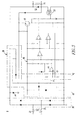
- the electronic circuit 8 is a printed circuit (PC) board 10 as shown in Figure 2 .
- the disclosed PC board 10 filters out noise and voltage surges to provide a clean power source for the motor 4.
- the electronic circuit 8 includes a current sensor 12 structured to sense current flowing to the motor input 6, a voltage sensor 14 structured to sense voltage to be applied to the motor input 6, a first detector 16 structured to detect a current spike from the sensed current and responsively limit a magnitude of the current flowing to the motor input 6, a second detector 18 structured to detect a voltage spike from the sensed voltage and responsively limit a magnitude of the voltage applied to the motor input 6, a first filter 20 structured to filter the current flowing to the motor input 6, and a second filter 22 structured to filter the voltage applied to the motor input 6.
- FIG. 2 shows that the example PC board 10 includes the example filters 20,22, the disclosed concept can employ zero, one or both of the example filters 20,22.
- Figure 3 shows the electrical circuit 8 of the example PC board 10 ( Figure 2 ), which protects the motor 4 ( Figure 1 ) from damage.
- the electrical circuit 8 functions to make the motor 4 less likely to burn up and, also, to make the electrical switching apparatus 100 less likely to have mechanical problems. This improves overall product performance and quality.
- the electrical circuit 8 protects voltage sensitive components by providing clamping capabilities, low leakage and fast response times. This protects the motor 4 from voltage irregularities, such as over voltages and/or spikes, that could damage the motor 4.
- the example electrical circuit 8 can readily be configured to input an AC voltage of about 110 VAC to about 240 VAC, and to output a DC voltage to the motor 4 of about 24 VDC to about 250 VDC.
- An H-bridge circuit 30 converts the incoming, unfiltered AC voltage from the two input conductors 32 to DC voltage.
- a transient voltage suppressor (TVS) 34 filters the DC voltage applied to the input of the motor 4 at the two output conductors 36.
- Another TVS 35 filters the input AC voltage.
- An over voltage protection circuit 38 includes a voltage reference circuit 40 having a reference voltage 41 and a voltage divider circuit 42 having a divided voltage 43.
- An operational amplifier 44 compares the reference voltage 41 and the divided voltage 43, in order to control the output DC voltage to desired levels.
- a time delay circuit 46 allows the electronic circuit 8 to have a purposeful delay in the delivery of output DC power until the desired DC power is available for output to the motor 4.
- a PNP transistor 48 functions as a voltage regulator in the electronic circuit 8.
- a MOSFET 50 functions as a switch to turn on and turn off the output DC power, in order to provide the desired DC voltage output.
- a fly back diode 52 protects the motor 8 by creating heat using excess inductance.
- the voltage reference circuit 40 includes a zener diode (not numbered), which is employed to clip current peaks/spikes. This reduces the magnitude of the current flowing to the input 6 ( Figure 1 ) of the motor 4.
- the motor 4 of Figure 1 is selected from the group consisting of a charging motor, a drill motor, and a power tool motor.
- a charging motor a drill motor
- a power tool motor a power tool motor
- the input power to the motor 4 is less than or equal to about 2000 watts.
- the motor 4 is selected from the group consisting of a DC motor, and an AC motor.
- a conventional DC/AC module is electrically connected between the output conductors 36 ( Figure 3 ) and the input 6 ( Figure 1 ) of the AC motor 4.
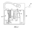
- an electrical switching apparatus 100 includes separable contacts 102 (shown in block form for ease of illustration), an operating mechanism 103 structured to open and close the separable contacts 102, and a motor 104 cooperating with the operating mechanism 103 to open or close the separable contacts 102.
- the motor 104 has an input 106 structured to input power.
- the electrical switching apparatus 100 also includes an electronic circuit 108, which can be the same as or similar to the electronic circuit 8 of Figure 1 , structured to condition the input power to the motor 104.
- the electrical switching apparatus 100 is a draw-out circuit breaker shown with the front cover removed for ease of illustration.
- the disclosed PC board 10 of Figure 2 can be mounted within the electrical switching apparatus 100, such as an example medium voltage, draw-out vacuum circuit breaker, in which the motor 104 is an example charging motor, and the PC board 10 provides a motor protection circuit.
- the operating mechanism 103 includes a number of closing springs 110.
- the example charging motor 104 is structured to charge the number of closing springs 110. Opening springs (not shown) are charged via the discharge of the number of closing springs 110.
- the charging motor 104 charges the number of closing springs 110 of the operating mechanism 103.
- the motor 104 can be about a 24 VDC to about 250 VDC motor, or about a 120 VAC to about 230 VAC motor, with a charging time of less than 12 mS and an insulation voltage of 2000 V at 50 Hz for 1 minute.
- the operating mechanism closing springs 110 can be charged manually.
- the PC board 10 senses both current and voltage. If a voltage spike or a current spike is detected, then the electronic motor protection circuit limits the voltage and/or current peaks to avoid damage to the motor 104. This increases the robustness of the motor system in order to reduce field problems.
- the electrical switching apparatus 100 is selected from the group consisting of a low voltage circuit breaker, a medium voltage circuit breaker, and a high voltage circuit breaker.
- the electrical switching apparatus 100 is a vacuum circuit breaker.
- the motor 104 is selected from the group consisting of a DC motor, and an AC motor.
- the disclosed concept applies to relatively small motors that can be used, for example and without limitation, as charging motors on low, medium, and high voltage circuit breakers.
- the disclosed concept can be applied to a wide range of other types of motors (e.g., without limitation, commercial drill motors; other commercial motors; motors for power tools).
- the motors can be, for example and without limitation, about 2000 watts or smaller.
- the disclosed concept increases the robustness of relatively small motors and decreases field returns thereof.
Landscapes
- Control Of Electric Motors In General (AREA)
- Control Of Direct Current Motors (AREA)
Abstract
Description
- The disclosed concept pertains generally to electromechanical apparatus and, more particularly, to electromechanical apparatus including a motor. The disclosed concept further pertains to electrical switching apparatus including a motor.
- An electrical switching apparatus typically includes at least one bus assembly having separable contacts, and an operating mechanism. The separable contacts include a fixed contact and a movable contact. Each contact is coupled to, and in electrical communication with, a conductive bus that is further coupled to, and in electrical communication with, a line or a load.
- If the electrical switching apparatus is a circuit interrupter, then it typically includes a trip device structured to detect an overcurrent condition and to actuate the operating mechanism. The operating mechanism is structured to both open the contacts, either manually or following actuation by the trip device, and close the contacts.
- In some circuit interrupters, the operating mechanism includes both a closing assembly having a number of closing springs and an opening assembly having a number of opening springs. These assemblies may have common elements that are structured to move the movable contact between a first, open position, wherein the separable contacts are separated, and a second, closed position, wherein the separable contacts are coupled and in electrical communication. The operating mechanism may also include a rotatable pole shaft that is coupled to the movable contact and structured to move each movable contact between the closed position and the open position. Elements of both the closing assembly and the opening assembly are coupled to the pole shaft so as to effect the closing and opening of the contacts.
- In certain circuit interrupters, typically, the force required to close the separable contacts is greater than what a human may apply. As such, the operating mechanism typically includes a mechanical closing assembly to close the separable contacts. The closing assembly, typically, includes at least one stored energy device, such as a spring, and/or a motor. A common configuration includes a motor that compresses one or more springs in the closing assembly. The closing springs are coupled to a cam roller that engages a cam coupled to the motor. As the motor rotates the cam, the closing springs are compressed or charged. The closing springs are maintained in a compressed configuration by a latch assembly. The latch assembly is actuated by a user to initiate a closing procedure. The closing assembly is structured to apply the energy stored in the springs to a toggle assembly so as to cause the pole shaft to rotate and close the separable contacts.
- The charging of the closing springs is typically accomplished via the motor. The motor has an output shaft that is coupled, directly or indirectly, to the shaft of the charging cam. In addition to the charging motor, most electrical switching apparatus include an elongated manual charging handle. The charging handle also acts upon the shaft of the charging cam either directly or indirectly.
- Motors are frequently damaged in the field. Several potential causes include assembly error (e.g., without limitation, operator error in assembling a motor or its components in its intended application) and manufacturing error (e.g., without limitation, manufacturing or other defects in motor components).
- There is room for improvement in electrical switching apparatus including a motor.
- There is further room for improvement in electromechanical apparatus including a motor.
- A relatively large number of failures of motors can be attributed to an unexpected increase in voltage and/or current. In addition, voltage surges and/or spikes can create problems. These issues can be caused by use of an unfiltered power supply and/or a bad power source.
- These needs and others are met by embodiments of the disclosed concept, which provides an electronic circuit to condition the input power to a motor. For example and without limitation, the electronic circuit filters the voltage and the current, and provides peak cutting and spike detection, in order to avoid damage to the motor.
- In accordance with one aspect of the disclosed concept, an electromechanical apparatus comprises: a motor comprising an input structured to input power; and an electronic circuit structured to condition the input power to the motor.
- The electronic circuit may comprise a current sensor structured to sense current flowing to the input of the motor, a voltage sensor structured to sense voltage to be applied to the input of the motor, a first detector structured to detect a current spike from the sensed current and responsively limit a magnitude of the current flowing to the input of the motor, a second detector structured to detect a voltage spike from the sensed voltage and responsively limit a magnitude of the voltage applied to the input of the motor, a first filter structured to filter the current flowing to the input of the motor, and a second filter structured to filter the voltage applied to the input of the motor.
- The electronic circuit may comprise a current sensor structured to sense current flowing to the input of the motor, a voltage sensor structured to sense voltage to be applied to the input of the motor, a first detector structured to detect a current spike from the sensed current and responsively limit a magnitude of the current flowing to the input of the motor, and a second detector structured to detect a voltage spike from the sensed voltage and responsively limit a magnitude of the voltage applied to the input of the motor.
- The electronic circuit may comprise at least one of a first filter structured to filter current flowing to the input of the motor, and a second filter structured to filter voltage applied to the input of the motor.
- As another aspect of the disclosed concept, an electrical switching apparatus comprises: separable contacts; an operating mechanism structured to open and close the separable contacts; a motor cooperating with the operating mechanism to open or close the separable contacts, the motor comprising an input structured to input power; and an electronic circuit structured to condition the input power to the motor.
- The electronic circuit may be a motor protection circuit.
- A full understanding of the disclosed concept can be gained from the following description of the preferred embodiments when read in conjunction with the accompanying drawings in which:
-
Figure 1 is a block diagram of an electromechanical apparatus including a motor and an electronic circuit in accordance with embodiments of the disclosed concept. -
Figure 2 is a block diagram in schematic form of the electronic circuit ofFigure 1 . -
Figure 3 is a block diagram in schematic form of the electronic circuit ofFigure 1 . -
Figure 4 is a vertical elevation view of an electrical switching apparatus including a motor and an electronic circuit in accordance with another embodiment of the disclosed concept. - As employed herein, the term "number" shall mean one or an integer greater than one (i.e., a plurality).
- As employed herein, the term "condition" shall mean to filter or limit noise of a voltage or current, to limit a magnitude of a voltage spike or a current spike, or to put input power into a proper state for a motor.
- As employed herein, the statement that two or more parts are "connected" or "coupled" together shall mean that the parts are joined together either directly or joined through one or more intermediate parts. Further, as employed herein, the statement that two or more parts are "attached" shall mean that the parts are joined together directly.
- The disclosed concept is described in association with an electromechanical apparatus, such as a circuit breaker, although the disclosed concept is applicable to a wide range of electromechanical apparatus including a motor.
- Referring to
Figure 1 , an electromechanical apparatus 2 (e.g., without limitation, an electromechanical device; an electromechanical assembly) includes amotor 4 having an input 6 structured to input power, and anelectronic circuit 8 structured to condition the input power from a power source 9 (shown in phantom line drawing) to themotor 4. - The
electronic circuit 8 is a printed circuit (PC)board 10 as shown inFigure 2 . The disclosedPC board 10 filters out noise and voltage surges to provide a clean power source for themotor 4. - The
electronic circuit 8 includes acurrent sensor 12 structured to sense current flowing to the motor input 6, avoltage sensor 14 structured to sense voltage to be applied to the motor input 6, afirst detector 16 structured to detect a current spike from the sensed current and responsively limit a magnitude of the current flowing to the motor input 6, asecond detector 18 structured to detect a voltage spike from the sensed voltage and responsively limit a magnitude of the voltage applied to the motor input 6, afirst filter 20 structured to filter the current flowing to the motor input 6, and asecond filter 22 structured to filter the voltage applied to the motor input 6. - Although
Figure 2 shows that theexample PC board 10 includes theexample filters example filters -
Figure 3 shows theelectrical circuit 8 of the example PC board 10 (Figure 2 ), which protects the motor 4 (Figure 1 ) from damage. Theelectrical circuit 8 functions to make themotor 4 less likely to burn up and, also, to make theelectrical switching apparatus 100 less likely to have mechanical problems. This improves overall product performance and quality. Theelectrical circuit 8 protects voltage sensitive components by providing clamping capabilities, low leakage and fast response times. This protects themotor 4 from voltage irregularities, such as over voltages and/or spikes, that could damage themotor 4. The exampleelectrical circuit 8 can readily be configured to input an AC voltage of about 110 VAC to about 240 VAC, and to output a DC voltage to themotor 4 of about 24 VDC to about 250 VDC. - An H-
bridge circuit 30 converts the incoming, unfiltered AC voltage from the two input conductors 32 to DC voltage. - A transient voltage suppressor (TVS) 34 filters the DC voltage applied to the input of the
motor 4 at the twooutput conductors 36. AnotherTVS 35 filters the input AC voltage. - An over
voltage protection circuit 38 includes a voltage reference circuit 40 having a reference voltage 41 and avoltage divider circuit 42 having a divided voltage 43. Anoperational amplifier 44 compares the reference voltage 41 and the divided voltage 43, in order to control the output DC voltage to desired levels. - A time delay circuit 46 allows the
electronic circuit 8 to have a purposeful delay in the delivery of output DC power until the desired DC power is available for output to themotor 4. - A
PNP transistor 48 functions as a voltage regulator in theelectronic circuit 8. AMOSFET 50 functions as a switch to turn on and turn off the output DC power, in order to provide the desired DC voltage output. These sense the voltage to be applied to the input of themotor 4, detect a voltage spike from the sensed voltage and responsively limit a magnitude of the voltage applied to the input of the motor. - A fly back
diode 52 protects themotor 8 by creating heat using excess inductance. - In
Figure 3 , the voltage reference circuit 40 includes a zener diode (not numbered), which is employed to clip current peaks/spikes. This reduces the magnitude of the current flowing to the input 6 (Figure 1 ) of themotor 4. - The
motor 4 ofFigure 1 is selected from the group consisting of a charging motor, a drill motor, and a power tool motor. However, it will be appreciated that the disclosed concept is applicable to a wide range of different types of motors. - As a non-limiting example, the input power to the
motor 4 is less than or equal to about 2000 watts. - The
motor 4 is selected from the group consisting of a DC motor, and an AC motor. For an AC motor, for example and without limitation, a conventional DC/AC module is electrically connected between the output conductors 36 (Figure 3 ) and the input 6 (Figure 1 ) of theAC motor 4. - Referring to
Figure 4 , anelectrical switching apparatus 100 includes separable contacts 102 (shown in block form for ease of illustration), anoperating mechanism 103 structured to open and close theseparable contacts 102, and amotor 104 cooperating with theoperating mechanism 103 to open or close theseparable contacts 102. Themotor 104 has aninput 106 structured to input power. Theelectrical switching apparatus 100 also includes anelectronic circuit 108, which can be the same as or similar to theelectronic circuit 8 ofFigure 1 , structured to condition the input power to themotor 104. In this example, theelectrical switching apparatus 100 is a draw-out circuit breaker shown with the front cover removed for ease of illustration. - The disclosed
PC board 10 ofFigure 2 can be mounted within theelectrical switching apparatus 100, such as an example medium voltage, draw-out vacuum circuit breaker, in which themotor 104 is an example charging motor, and thePC board 10 provides a motor protection circuit. Theoperating mechanism 103 includes a number of closing springs 110. Theexample charging motor 104 is structured to charge the number of closing springs 110. Opening springs (not shown) are charged via the discharge of the number of closing springs 110. The chargingmotor 104 charges the number of closing springs 110 of theoperating mechanism 103. - For example and without limitation, the
motor 104 can be about a 24 VDC to about 250 VDC motor, or about a 120 VAC to about 230 VAC motor, with a charging time of less than 12 mS and an insulation voltage of 2000 V at 50 Hz for 1 minute. In the event of a loss of power, the operating mechanism closing springs 110 can be charged manually. ThePC board 10 senses both current and voltage. If a voltage spike or a current spike is detected, then the electronic motor protection circuit limits the voltage and/or current peaks to avoid damage to themotor 104. This increases the robustness of the motor system in order to reduce field problems. - The
electrical switching apparatus 100 is selected from the group consisting of a low voltage circuit breaker, a medium voltage circuit breaker, and a high voltage circuit breaker. - The
electrical switching apparatus 100 is a vacuum circuit breaker. - The
motor 104 is selected from the group consisting of a DC motor, and an AC motor. - The disclosed concept applies to relatively small motors that can be used, for example and without limitation, as charging motors on low, medium, and high voltage circuit breakers. However, the disclosed concept can be applied to a wide range of other types of motors (e.g., without limitation, commercial drill motors; other commercial motors; motors for power tools). In general, the motors can be, for example and without limitation, about 2000 watts or smaller.
- The disclosed concept increases the robustness of relatively small motors and decreases field returns thereof.
- While specific embodiments of the disclosed concept have been described in detail, it will be appreciated by those skilled in the art that various modifications and alternatives to those details could be developed in light of the overall teachings of the disclosure. Accordingly, the particular arrangements disclosed are meant to be illustrative only and not limiting as to the scope of the disclosed concept which is to be given the full breadth of the claims appended and any and all equivalents thereof.
-
- 2
- electromechanical apparatus
- 4
- motor
- 6
- input
- 8
- electronic circuit
- 9
- power source
- 10
- printed circuit (PC) board
- 12
- current sensor
- 14
- voltage sensor
- 16
- first detector
- 18
- second detector
- 20
- first filter
- 22
- second filter
- 30
- H-bridge circuit
- 32
- two input conductors
- 34
- transient voltage suppressor (TVS)
- 35
- TVS
- 36
- two output conductors
- 38
- over voltage protection circuit
- 40
- voltage reference circuit
- 41
- reference voltage
- 42
- voltage divider circuit
- 43
- divided voltage
- 44
- operational amplifier
- 46
- time delay circuit
- 48
- PNP transistor
- 50
- MOSFET
- 52
- fly back diode
- 100
- electrical switching apparatus
- 102
- separable contacts
- 103
- operating mechanism
- 104
- motor
- 106
- input
- 108
- electronic circuit
- 110
- closing springs
Claims (15)
- An electromechanical apparatus (2) comprising:a motor (4) comprising an input (6) structured to input power; andan electronic circuit (8) structured to condition the input power to said motor.
- The electromechanical apparatus (2) of Claim 1 wherein said electronic circuit comprises a current sensor (12) structured to sense current flowing to the input of said motor, a voltage sensor (14) structured to sense voltage to be applied to the input of said motor, a first detector (16) structured to detect a current spike from said sensed current and responsively limit a magnitude of said current flowing to the input of said motor, a second detector (18) structured to detect a voltage spike from said sensed voltage and responsively limit a magnitude of said voltage applied to the input of said motor, a first filter (20) structured to filter said current flowing to the input of said motor, and a second filter (22) structured to filter said voltage applied to the input of said motor.
- The electromechanical apparatus (2) of Claim 1 wherein said electronic circuit comprises at least one of a first filter (20) structured to filter current flowing to the input of said motor, and a second filter (22) structured to filter voltage applied to the input of said motor.
- The electromechanical apparatus (2) of Claim 1 wherein said electronic circuit comprises a first filter (20) structured to filter current flowing to the input of said motor, and a second filter (22) structured to filter voltage applied to the input of said motor.
- The electromechanical apparatus (2) of Claim 1 wherein said electronic circuit comprises a current sensor (12) structured to sense current flowing to the input of said motor, a voltage sensor (14) structured to sense voltage to be applied to the input of said motor, a first detector (16) structured to detect a current spike from said sensed current and responsively limit a magnitude of said current flowing to the input of said motor, and a second detector (18) structured to detect a voltage spike from said sensed voltage and responsively limit a magnitude of said voltage applied to the input of said motor.
- The electromechanical apparatus (2) of Claim 5 wherein said electronic circuit comprises at least one of a first filter (20) structured to filter current flowing to the input of said motor, and a second filter (22) structured to filter voltage applied to the input of said motor.
- The electromechanical apparatus (2) of Claim 1 wherein said motor is selected from the group consisting of a charging motor, a drill motor, a power tool motor, a DC motor, and an AC motor.
- An electrical switching apparatus (100) comprising:separable contacts (102);an operating mechanism (103) structured to open and close said separable contacts; andsaid electromechanical apparatus of Claim 1,wherein said motor cooperates with said operating mechanism to open or close said separable contacts.
- The electrical switching apparatus (100) of Claim 8 wherein said electrical switching apparatus is selected from the group consisting of a low voltage circuit breaker, a medium voltage circuit breaker, and a high voltage circuit breaker.
- The electrical switching apparatus (100) of Claim 8 wherein said electrical switching apparatus is selected from the group consisting of a draw-out circuit breaker, and a vacuum circuit breaker.
- The electrical switching apparatus (100) of Claim 8 wherein said electronic circuit is a motor protection circuit.
- The electrical switching apparatus (100) of Claim 8 wherein said motor is selected from the group consisting of a DC motor, an AC motor, and a charging motor.
- The electrical switching apparatus (100) of Claim 12 wherein said motor is said charging motor; wherein said operating mechanism comprises a number of closing springs (110); and wherein said charging motor is structured to charge said number of closing springs.
- The electrical switching apparatus (100) of Claim 8 wherein said electronic circuit comprises a current sensor (12) structured to sense current flowing to the input of said motor, a voltage sensor (14) structured to sense voltage to be applied to the input of said motor, a first detector (16) structured to detect a current spike from said sensed current and responsively limit a magnitude of said current flowing to the input of said motor, and a second detector (18) structured to detect a voltage spike from said sensed voltage and responsively limit a magnitude of said voltage applied to the input of said motor.
- The electrical switching apparatus (100) of Claim 8 wherein said electronic circuit comprises at least one of a first filter (20) structured to filter current flowing to the input of said motor, and a second filter (22) structured to filter voltage applied to the input of said motor.
Applications Claiming Priority (1)
| Application Number | Priority Date | Filing Date | Title |
|---|---|---|---|
| US13/571,555 US9634478B2 (en) | 2012-08-10 | 2012-08-10 | Electromechanical apparatus and electrical switching apparatus employing electronic circuit to condition motor input power |
Publications (3)
| Publication Number | Publication Date |
|---|---|
| EP2696461A2 true EP2696461A2 (en) | 2014-02-12 |
| EP2696461A3 EP2696461A3 (en) | 2014-03-26 |
| EP2696461B1 EP2696461B1 (en) | 2015-12-02 |
Family
ID=48746343
Family Applications (1)
| Application Number | Title | Priority Date | Filing Date |
|---|---|---|---|
| EP13175331.1A Not-in-force EP2696461B1 (en) | 2012-08-10 | 2013-07-05 | Electromechanical apparatus and electrical switching apparatus employing electronic circuit to condition motor input power |
Country Status (3)
| Country | Link |
|---|---|
| US (1) | US9634478B2 (en) |
| EP (1) | EP2696461B1 (en) |
| CN (1) | CN103578801B (en) |
Families Citing this family (2)
| Publication number | Priority date | Publication date | Assignee | Title |
|---|---|---|---|---|
| US10899465B2 (en) * | 2018-01-05 | 2021-01-26 | Gopro, Inc. | Motor control optimizations for unmanned aerial vehicles |
| US11855443B2 (en) | 2022-05-04 | 2023-12-26 | Buyers Products Company | Control system and method for double check |
Family Cites Families (11)
| Publication number | Priority date | Publication date | Assignee | Title |
|---|---|---|---|---|
| US3953740A (en) * | 1971-09-30 | 1976-04-27 | Cliff Granberry Corporation | Remote power supply units for vehicles |
| US5744921A (en) | 1996-05-02 | 1998-04-28 | Siemens Electric Limited | Control circuit for five-phase brushless DC motor |
| US6545481B1 (en) * | 2000-11-20 | 2003-04-08 | International Business Machines Corporation | Power interruption detection |
| US20040105664A1 (en) | 2002-12-03 | 2004-06-03 | Mladen Ivankovic | Linear electric motor controller and system for providing linear speed control |
| US6992873B2 (en) | 2003-03-05 | 2006-01-31 | Lewis Joseph S | Automated AC line filter and surge suppression apparatus and method |
| DE20308760U1 (en) * | 2003-06-05 | 2003-08-21 | Wessel-Werk GmbH, 51580 Reichshof | Vacuum cleaner has brush design and a permanent magnet motor arranged so that power consumption is limited independently of the width of the brush |
| US8400095B2 (en) * | 2010-04-14 | 2013-03-19 | System General Corporation | Constant-speed control circuit for BLDC motors |
| TW201318293A (en) * | 2011-10-19 | 2013-05-01 | Anpec Electronics Corp | Circuit protection method and motor control circuit |
| US8710389B2 (en) * | 2011-11-15 | 2014-04-29 | Eaton Corporation | Vacuum switch and electrode assembly therefor |
| US8861144B2 (en) * | 2011-11-15 | 2014-10-14 | Eaton Corporation | Triggered arc flash arrester and switchgear system including the same |
| US8816631B2 (en) * | 2012-03-13 | 2014-08-26 | Rockwell Automation Technologies, Inc. | Apparatus and method for energy efficient motor drive standby operation |
-
2012
- 2012-08-10 US US13/571,555 patent/US9634478B2/en not_active Expired - Fee Related
-
2013
- 2013-07-05 EP EP13175331.1A patent/EP2696461B1/en not_active Not-in-force
- 2013-08-07 CN CN201310340964.6A patent/CN103578801B/en not_active Expired - Fee Related
Also Published As
| Publication number | Publication date |
|---|---|
| EP2696461A3 (en) | 2014-03-26 |
| US9634478B2 (en) | 2017-04-25 |
| CN103578801A (en) | 2014-02-12 |
| US20140043117A1 (en) | 2014-02-13 |
| CN103578801B (en) | 2017-06-23 |
| EP2696461B1 (en) | 2015-12-02 |
Similar Documents
| Publication | Publication Date | Title |
|---|---|---|
| CN101114555B (en) | Circuit interrupter including point-on-wave controller and voltage sensors | |
| CA2639864C (en) | Circuit interrupter | |
| CN106415968B (en) | Semi-voltage dependent circuit breaker | |
| US8659857B2 (en) | Leakage current detection and interruption circuit powered by leakage current | |
| US11552468B2 (en) | Electrical device with power quality event protection and associated method | |
| US20220021335A1 (en) | Photovoltaic string combiner box with protection functions | |
| CN102543609A (en) | Leakage circuit breaker for distribution board and distribution board system | |
| US7280338B2 (en) | Power supply circuit, back-pack power supply module and circuit interrupter including the same | |
| Solangi et al. | Selective coordination of GaN-based solid state circuit breakers | |
| KR101261496B1 (en) | Circuit for smart-earthing using permanent magnetic actuator | |
| KR102860651B1 (en) | crossing gate | |
| US9634478B2 (en) | Electromechanical apparatus and electrical switching apparatus employing electronic circuit to condition motor input power | |
| CN101179188A (en) | Second open circuit protector of current mutual inductor | |
| EP3084796A1 (en) | Shunt trip control circuits using shunt trip signal accumulator and methods of operating the same | |
| RU2464661C2 (en) | Electric drive for switching devices arranged as capable of electric energy accumulation | |
| CN220272392U (en) | Intelligent contactor | |
| US11063419B2 (en) | GFCI with capacitive power supply circuit | |
| Kaiser et al. | A Comprehensive Approach for Safety in DC-Microgrids | |
| CN204614686U (en) | electrical switchgear | |
| RU2333585C1 (en) | Protector for constant current electrical equipment | |
| JP3485976B2 (en) | Remote test equipment for earth leakage breaker | |
| CN109193561B (en) | An integrated residual current operated circuit breaker | |
| WO2024035250A1 (en) | Neutral tear protection device in low-voltage electrical installations | |
| WO2025233900A1 (en) | Circuit breaker with super-capacitor energy arrester | |
| KR20040097433A (en) | High Speed Earthing Switch for Neutral Phase of Main Transformer |
Legal Events
| Date | Code | Title | Description |
|---|---|---|---|
| AK | Designated contracting states |
Kind code of ref document: A2 Designated state(s): AL AT BE BG CH CY CZ DE DK EE ES FI FR GB GR HR HU IE IS IT LI LT LU LV MC MK MT NL NO PL PT RO RS SE SI SK SM TR |
|
| AX | Request for extension of the european patent |
Extension state: BA ME |
|
| PUAI | Public reference made under article 153(3) epc to a published international application that has entered the european phase |
Free format text: ORIGINAL CODE: 0009012 |
|
| PUAL | Search report despatched |
Free format text: ORIGINAL CODE: 0009013 |
|
| AK | Designated contracting states |
Kind code of ref document: A3 Designated state(s): AL AT BE BG CH CY CZ DE DK EE ES FI FR GB GR HR HU IE IS IT LI LT LU LV MC MK MT NL NO PL PT RO RS SE SI SK SM TR |
|
| AX | Request for extension of the european patent |
Extension state: BA ME |
|
| RIC1 | Information provided on ipc code assigned before grant |
Ipc: H02H 3/26 20060101AFI20140219BHEP Ipc: H02H 9/00 20060101ALI20140219BHEP Ipc: H02H 7/08 20060101ALI20140219BHEP |
|
| 17P | Request for examination filed |
Effective date: 20140623 |
|
| RBV | Designated contracting states (corrected) |
Designated state(s): AL AT BE BG CH CY CZ DE DK EE ES FI FR GB GR HR HU IE IS IT LI LT LU LV MC MK MT NL NO PL PT RO RS SE SI SK SM TR |
|
| GRAP | Despatch of communication of intention to grant a patent |
Free format text: ORIGINAL CODE: EPIDOSNIGR1 |
|
| INTG | Intention to grant announced |
Effective date: 20150605 |
|
| RAP1 | Party data changed (applicant data changed or rights of an application transferred) |
Owner name: EATON CORPORATION |
|
| GRAS | Grant fee paid |
Free format text: ORIGINAL CODE: EPIDOSNIGR3 |
|
| GRAA | (expected) grant |
Free format text: ORIGINAL CODE: 0009210 |
|
| AK | Designated contracting states |
Kind code of ref document: B1 Designated state(s): AL AT BE BG CH CY CZ DE DK EE ES FI FR GB GR HR HU IE IS IT LI LT LU LV MC MK MT NL NO PL PT RO RS SE SI SK SM TR |
|
| REG | Reference to a national code |
Ref country code: GB Ref legal event code: FG4D |
|
| REG | Reference to a national code |
Ref country code: AT Ref legal event code: REF Ref document number: 764005 Country of ref document: AT Kind code of ref document: T Effective date: 20151215 Ref country code: CH Ref legal event code: EP |
|
| REG | Reference to a national code |
Ref country code: IE Ref legal event code: FG4D |
|
| REG | Reference to a national code |
Ref country code: DE Ref legal event code: R096 Ref document number: 602013003972 Country of ref document: DE |
|
| REG | Reference to a national code |
Ref country code: NL Ref legal event code: MP Effective date: 20160302 |
|
| REG | Reference to a national code |
Ref country code: LT Ref legal event code: MG4D |
|
| REG | Reference to a national code |
Ref country code: AT Ref legal event code: MK05 Ref document number: 764005 Country of ref document: AT Kind code of ref document: T Effective date: 20151202 |
|
| PG25 | Lapsed in a contracting state [announced via postgrant information from national office to epo] |
Ref country code: LT Free format text: LAPSE BECAUSE OF FAILURE TO SUBMIT A TRANSLATION OF THE DESCRIPTION OR TO PAY THE FEE WITHIN THE PRESCRIBED TIME-LIMIT Effective date: 20151202 Ref country code: NO Free format text: LAPSE BECAUSE OF FAILURE TO SUBMIT A TRANSLATION OF THE DESCRIPTION OR TO PAY THE FEE WITHIN THE PRESCRIBED TIME-LIMIT Effective date: 20160302 Ref country code: ES Free format text: LAPSE BECAUSE OF FAILURE TO SUBMIT A TRANSLATION OF THE DESCRIPTION OR TO PAY THE FEE WITHIN THE PRESCRIBED TIME-LIMIT Effective date: 20151202 |
|
| PG25 | Lapsed in a contracting state [announced via postgrant information from national office to epo] |
Ref country code: PL Free format text: LAPSE BECAUSE OF FAILURE TO SUBMIT A TRANSLATION OF THE DESCRIPTION OR TO PAY THE FEE WITHIN THE PRESCRIBED TIME-LIMIT Effective date: 20151202 Ref country code: LV Free format text: LAPSE BECAUSE OF FAILURE TO SUBMIT A TRANSLATION OF THE DESCRIPTION OR TO PAY THE FEE WITHIN THE PRESCRIBED TIME-LIMIT Effective date: 20151202 Ref country code: GR Free format text: LAPSE BECAUSE OF FAILURE TO SUBMIT A TRANSLATION OF THE DESCRIPTION OR TO PAY THE FEE WITHIN THE PRESCRIBED TIME-LIMIT Effective date: 20160303 Ref country code: NL Free format text: LAPSE BECAUSE OF FAILURE TO SUBMIT A TRANSLATION OF THE DESCRIPTION OR TO PAY THE FEE WITHIN THE PRESCRIBED TIME-LIMIT Effective date: 20151202 Ref country code: SE Free format text: LAPSE BECAUSE OF FAILURE TO SUBMIT A TRANSLATION OF THE DESCRIPTION OR TO PAY THE FEE WITHIN THE PRESCRIBED TIME-LIMIT Effective date: 20151202 Ref country code: FI Free format text: LAPSE BECAUSE OF FAILURE TO SUBMIT A TRANSLATION OF THE DESCRIPTION OR TO PAY THE FEE WITHIN THE PRESCRIBED TIME-LIMIT Effective date: 20151202 Ref country code: AT Free format text: LAPSE BECAUSE OF FAILURE TO SUBMIT A TRANSLATION OF THE DESCRIPTION OR TO PAY THE FEE WITHIN THE PRESCRIBED TIME-LIMIT Effective date: 20151202 Ref country code: RS Free format text: LAPSE BECAUSE OF FAILURE TO SUBMIT A TRANSLATION OF THE DESCRIPTION OR TO PAY THE FEE WITHIN THE PRESCRIBED TIME-LIMIT Effective date: 20151202 |
|
| REG | Reference to a national code |
Ref country code: FR Ref legal event code: PLFP Year of fee payment: 4 |
|
| PG25 | Lapsed in a contracting state [announced via postgrant information from national office to epo] |
Ref country code: IS Free format text: LAPSE BECAUSE OF FAILURE TO SUBMIT A TRANSLATION OF THE DESCRIPTION OR TO PAY THE FEE WITHIN THE PRESCRIBED TIME-LIMIT Effective date: 20151202 |
|
| PG25 | Lapsed in a contracting state [announced via postgrant information from national office to epo] |
Ref country code: CZ Free format text: LAPSE BECAUSE OF FAILURE TO SUBMIT A TRANSLATION OF THE DESCRIPTION OR TO PAY THE FEE WITHIN THE PRESCRIBED TIME-LIMIT Effective date: 20151202 Ref country code: IT Free format text: LAPSE BECAUSE OF FAILURE TO SUBMIT A TRANSLATION OF THE DESCRIPTION OR TO PAY THE FEE WITHIN THE PRESCRIBED TIME-LIMIT Effective date: 20151202 |
|
| PG25 | Lapsed in a contracting state [announced via postgrant information from national office to epo] |
Ref country code: EE Free format text: LAPSE BECAUSE OF FAILURE TO SUBMIT A TRANSLATION OF THE DESCRIPTION OR TO PAY THE FEE WITHIN THE PRESCRIBED TIME-LIMIT Effective date: 20151202 Ref country code: SM Free format text: LAPSE BECAUSE OF FAILURE TO SUBMIT A TRANSLATION OF THE DESCRIPTION OR TO PAY THE FEE WITHIN THE PRESCRIBED TIME-LIMIT Effective date: 20151202 Ref country code: IS Free format text: LAPSE BECAUSE OF FAILURE TO SUBMIT A TRANSLATION OF THE DESCRIPTION OR TO PAY THE FEE WITHIN THE PRESCRIBED TIME-LIMIT Effective date: 20160402 Ref country code: RO Free format text: LAPSE BECAUSE OF FAILURE TO SUBMIT A TRANSLATION OF THE DESCRIPTION OR TO PAY THE FEE WITHIN THE PRESCRIBED TIME-LIMIT Effective date: 20151202 Ref country code: PT Free format text: LAPSE BECAUSE OF FAILURE TO SUBMIT A TRANSLATION OF THE DESCRIPTION OR TO PAY THE FEE WITHIN THE PRESCRIBED TIME-LIMIT Effective date: 20160404 Ref country code: SK Free format text: LAPSE BECAUSE OF FAILURE TO SUBMIT A TRANSLATION OF THE DESCRIPTION OR TO PAY THE FEE WITHIN THE PRESCRIBED TIME-LIMIT Effective date: 20151202 |
|
| REG | Reference to a national code |
Ref country code: DE Ref legal event code: R097 Ref document number: 602013003972 Country of ref document: DE |
|
| PLBE | No opposition filed within time limit |
Free format text: ORIGINAL CODE: 0009261 |
|
| STAA | Information on the status of an ep patent application or granted ep patent |
Free format text: STATUS: NO OPPOSITION FILED WITHIN TIME LIMIT |
|
| PG25 | Lapsed in a contracting state [announced via postgrant information from national office to epo] |
Ref country code: DK Free format text: LAPSE BECAUSE OF FAILURE TO SUBMIT A TRANSLATION OF THE DESCRIPTION OR TO PAY THE FEE WITHIN THE PRESCRIBED TIME-LIMIT Effective date: 20151202 |
|
| 26N | No opposition filed |
Effective date: 20160905 |
|
| PG25 | Lapsed in a contracting state [announced via postgrant information from national office to epo] |
Ref country code: SI Free format text: LAPSE BECAUSE OF FAILURE TO SUBMIT A TRANSLATION OF THE DESCRIPTION OR TO PAY THE FEE WITHIN THE PRESCRIBED TIME-LIMIT Effective date: 20151202 |
|
| PG25 | Lapsed in a contracting state [announced via postgrant information from national office to epo] |
Ref country code: BE Free format text: LAPSE BECAUSE OF FAILURE TO SUBMIT A TRANSLATION OF THE DESCRIPTION OR TO PAY THE FEE WITHIN THE PRESCRIBED TIME-LIMIT Effective date: 20151202 |
|
| REG | Reference to a national code |
Ref country code: CH Ref legal event code: PL |
|
| PG25 | Lapsed in a contracting state [announced via postgrant information from national office to epo] |
Ref country code: MC Free format text: LAPSE BECAUSE OF FAILURE TO SUBMIT A TRANSLATION OF THE DESCRIPTION OR TO PAY THE FEE WITHIN THE PRESCRIBED TIME-LIMIT Effective date: 20151202 |
|
| PG25 | Lapsed in a contracting state [announced via postgrant information from national office to epo] |
Ref country code: LI Free format text: LAPSE BECAUSE OF NON-PAYMENT OF DUE FEES Effective date: 20160731 Ref country code: CH Free format text: LAPSE BECAUSE OF NON-PAYMENT OF DUE FEES Effective date: 20160731 |
|
| REG | Reference to a national code |
Ref country code: IE Ref legal event code: MM4A |
|
| REG | Reference to a national code |
Ref country code: FR Ref legal event code: PLFP Year of fee payment: 5 |
|
| PG25 | Lapsed in a contracting state [announced via postgrant information from national office to epo] |
Ref country code: IE Free format text: LAPSE BECAUSE OF NON-PAYMENT OF DUE FEES Effective date: 20160705 |
|
| PG25 | Lapsed in a contracting state [announced via postgrant information from national office to epo] |
Ref country code: LU Free format text: LAPSE BECAUSE OF NON-PAYMENT OF DUE FEES Effective date: 20160705 |
|
| GBPC | Gb: european patent ceased through non-payment of renewal fee |
Effective date: 20170705 |
|
| PG25 | Lapsed in a contracting state [announced via postgrant information from national office to epo] |
Ref country code: GB Free format text: LAPSE BECAUSE OF NON-PAYMENT OF DUE FEES Effective date: 20170705 |
|
| PG25 | Lapsed in a contracting state [announced via postgrant information from national office to epo] |
Ref country code: CY Free format text: LAPSE BECAUSE OF FAILURE TO SUBMIT A TRANSLATION OF THE DESCRIPTION OR TO PAY THE FEE WITHIN THE PRESCRIBED TIME-LIMIT Effective date: 20151202 Ref country code: HU Free format text: LAPSE BECAUSE OF FAILURE TO SUBMIT A TRANSLATION OF THE DESCRIPTION OR TO PAY THE FEE WITHIN THE PRESCRIBED TIME-LIMIT; INVALID AB INITIO Effective date: 20130705 |
|
| REG | Reference to a national code |
Ref country code: FR Ref legal event code: PLFP Year of fee payment: 6 |
|
| PG25 | Lapsed in a contracting state [announced via postgrant information from national office to epo] |
Ref country code: TR Free format text: LAPSE BECAUSE OF FAILURE TO SUBMIT A TRANSLATION OF THE DESCRIPTION OR TO PAY THE FEE WITHIN THE PRESCRIBED TIME-LIMIT Effective date: 20151202 Ref country code: MK Free format text: LAPSE BECAUSE OF FAILURE TO SUBMIT A TRANSLATION OF THE DESCRIPTION OR TO PAY THE FEE WITHIN THE PRESCRIBED TIME-LIMIT Effective date: 20151202 Ref country code: MT Free format text: LAPSE BECAUSE OF NON-PAYMENT OF DUE FEES Effective date: 20160731 Ref country code: HR Free format text: LAPSE BECAUSE OF FAILURE TO SUBMIT A TRANSLATION OF THE DESCRIPTION OR TO PAY THE FEE WITHIN THE PRESCRIBED TIME-LIMIT Effective date: 20151202 |
|
| PG25 | Lapsed in a contracting state [announced via postgrant information from national office to epo] |
Ref country code: BG Free format text: LAPSE BECAUSE OF FAILURE TO SUBMIT A TRANSLATION OF THE DESCRIPTION OR TO PAY THE FEE WITHIN THE PRESCRIBED TIME-LIMIT Effective date: 20151202 |
|
| PGFP | Annual fee paid to national office [announced via postgrant information from national office to epo] |
Ref country code: FR Payment date: 20180621 Year of fee payment: 6 |
|
| PG25 | Lapsed in a contracting state [announced via postgrant information from national office to epo] |
Ref country code: AL Free format text: LAPSE BECAUSE OF FAILURE TO SUBMIT A TRANSLATION OF THE DESCRIPTION OR TO PAY THE FEE WITHIN THE PRESCRIBED TIME-LIMIT Effective date: 20151202 |
|
| PGFP | Annual fee paid to national office [announced via postgrant information from national office to epo] |
Ref country code: DE Payment date: 20180620 Year of fee payment: 6 |
|
| REG | Reference to a national code |
Ref country code: DE Ref legal event code: R119 Ref document number: 602013003972 Country of ref document: DE |
|
| PG25 | Lapsed in a contracting state [announced via postgrant information from national office to epo] |
Ref country code: DE Free format text: LAPSE BECAUSE OF NON-PAYMENT OF DUE FEES Effective date: 20200201 |
|
| PG25 | Lapsed in a contracting state [announced via postgrant information from national office to epo] |
Ref country code: FR Free format text: LAPSE BECAUSE OF NON-PAYMENT OF DUE FEES Effective date: 20190731 |