EP2696447A1 - Connector, connector device, and battery unit - Google Patents
Connector, connector device, and battery unit Download PDFInfo
- Publication number
- EP2696447A1 EP2696447A1 EP11868842.3A EP11868842A EP2696447A1 EP 2696447 A1 EP2696447 A1 EP 2696447A1 EP 11868842 A EP11868842 A EP 11868842A EP 2696447 A1 EP2696447 A1 EP 2696447A1
- Authority
- EP
- European Patent Office
- Prior art keywords
- housing
- contact
- connector
- pair
- conductive members
- Prior art date
- Legal status (The legal status is an assumption and is not a legal conclusion. Google has not performed a legal analysis and makes no representation as to the accuracy of the status listed.)
- Granted
Links
Images







Classifications
-
- H—ELECTRICITY
- H01—ELECTRIC ELEMENTS
- H01R—ELECTRICALLY-CONDUCTIVE CONNECTIONS; STRUCTURAL ASSOCIATIONS OF A PLURALITY OF MUTUALLY-INSULATED ELECTRICAL CONNECTING ELEMENTS; COUPLING DEVICES; CURRENT COLLECTORS
- H01R13/00—Details of coupling devices of the kinds covered by groups H01R12/70 or H01R24/00 - H01R33/00
- H01R13/02—Contact members
- H01R13/04—Pins or blades for co-operation with sockets
-
- H—ELECTRICITY
- H01—ELECTRIC ELEMENTS
- H01R—ELECTRICALLY-CONDUCTIVE CONNECTIONS; STRUCTURAL ASSOCIATIONS OF A PLURALITY OF MUTUALLY-INSULATED ELECTRICAL CONNECTING ELEMENTS; COUPLING DEVICES; CURRENT COLLECTORS
- H01R13/00—Details of coupling devices of the kinds covered by groups H01R12/70 or H01R24/00 - H01R33/00
- H01R13/62—Means for facilitating engagement or disengagement of coupling parts or for holding them in engagement
- H01R13/629—Additional means for facilitating engagement or disengagement of coupling parts, e.g. aligning or guiding means, levers, gas pressure electrical locking indicators, manufacturing tolerances
- H01R13/631—Additional means for facilitating engagement or disengagement of coupling parts, e.g. aligning or guiding means, levers, gas pressure electrical locking indicators, manufacturing tolerances for engagement only
- H01R13/6315—Additional means for facilitating engagement or disengagement of coupling parts, e.g. aligning or guiding means, levers, gas pressure electrical locking indicators, manufacturing tolerances for engagement only allowing relative movement between coupling parts, e.g. floating connection
-
- H—ELECTRICITY
- H01—ELECTRIC ELEMENTS
- H01R—ELECTRICALLY-CONDUCTIVE CONNECTIONS; STRUCTURAL ASSOCIATIONS OF A PLURALITY OF MUTUALLY-INSULATED ELECTRICAL CONNECTING ELEMENTS; COUPLING DEVICES; CURRENT COLLECTORS
- H01R13/00—Details of coupling devices of the kinds covered by groups H01R12/70 or H01R24/00 - H01R33/00
- H01R13/46—Bases; Cases
- H01R13/514—Bases; Cases composed as a modular blocks or assembly, i.e. composed of co-operating parts provided with contact members or holding contact members between them
-
- H—ELECTRICITY
- H01—ELECTRIC ELEMENTS
- H01R—ELECTRICALLY-CONDUCTIVE CONNECTIONS; STRUCTURAL ASSOCIATIONS OF A PLURALITY OF MUTUALLY-INSULATED ELECTRICAL CONNECTING ELEMENTS; COUPLING DEVICES; CURRENT COLLECTORS
- H01R13/00—Details of coupling devices of the kinds covered by groups H01R12/70 or H01R24/00 - H01R33/00
- H01R13/02—Contact members
- H01R13/15—Pins, blades or sockets having separate spring member for producing or increasing contact pressure
-
- H—ELECTRICITY
- H01—ELECTRIC ELEMENTS
- H01R—ELECTRICALLY-CONDUCTIVE CONNECTIONS; STRUCTURAL ASSOCIATIONS OF A PLURALITY OF MUTUALLY-INSULATED ELECTRICAL CONNECTING ELEMENTS; COUPLING DEVICES; CURRENT COLLECTORS
- H01R4/00—Electrically-conductive connections between two or more conductive members in direct contact, i.e. touching one another; Means for effecting or maintaining such contact; Electrically-conductive connections having two or more spaced connecting locations for conductors and using contact members penetrating insulation
- H01R4/28—Clamped connections, spring connections
- H01R4/38—Clamped connections, spring connections utilising a clamping member acted on by screw or nut
- H01R4/40—Pivotable clamping member
-
- H—ELECTRICITY
- H01—ELECTRIC ELEMENTS
- H01R—ELECTRICALLY-CONDUCTIVE CONNECTIONS; STRUCTURAL ASSOCIATIONS OF A PLURALITY OF MUTUALLY-INSULATED ELECTRICAL CONNECTING ELEMENTS; COUPLING DEVICES; CURRENT COLLECTORS
- H01R4/00—Electrically-conductive connections between two or more conductive members in direct contact, i.e. touching one another; Means for effecting or maintaining such contact; Electrically-conductive connections having two or more spaced connecting locations for conductors and using contact members penetrating insulation
- H01R4/28—Clamped connections, spring connections
- H01R4/48—Clamped connections, spring connections utilising a spring, clip, or other resilient member
- H01R4/4854—Clamped connections, spring connections utilising a spring, clip, or other resilient member using a wire spring
- H01R4/4863—Coil spring
Definitions
- This invention relates to a connector, a connector device, and a battery unit and, in particular, relates to a connector, a connector device, and a battery unit which has a function of correcting the position offset with respect to a connection object.
- a plug-in connector (male) 100 comprising a terminal block body 120 attached to a panel 110, a conductive connection wiring board 130 attached to the terminal block body 120, a male pin receiving nut 140 incorporated in the terminal block body 120, a male pin 150 attached to the terminal block body 120 through the male pin receiving nut 140, and a plug-in connector housing 160 attached to the terminal block body 120 through the male pin 150 (see, e.g. Patent Document 1).
- the floating function required for plug-in connection between the plug-in connector (male) 100 and a plug-in connector (female) 170 is achieved by attaching the male pin 150 and the male pin receiving nut 140 to the terminal block body 120 with some play therebetween.
- Patent Document 1 JP-A-2003-346940
- this invention aims to solve the conventional problems, that is, it is an object of this invention to provide a connector, a connector device, and a battery unit which ensure a large floating amount of a contact with a simple structure and further which are small in the number of components to thereby reduce the workload for assembly.
- a connector comprises a first housing, a second housing attached to the first housing and forming a contact receiving portion jointly with the first housing, and a contact at least partially received in the contact receiving portion, wherein the second housing is attached to the first housing so as to be movable in a predetermined direction relative to the first housing, and wherein the contact is received in the contact receiving portion in a state where the contact is not fixed to the first housing or the second housing so as to be movable relative to the first housing and the second housing, whereby solving the above-mentioned problem.
- the contact may comprise a second contact portion disposed on the second housing side and adapted to contact with a connection object.
- the contact may further comprise a first contact portion disposed on the first housing side and adapted to contact with another connection object.
- the second housing may comprise a second control portion that controls a position and posture of the contact in the contact receiving portion and that pushes the contact when the first housing and the second housing move relative to each other.
- the first housing may comprise a first control portion that controls a position and posture of the contact in the contact receiving portion and that pushes the contact when the first housing and the second housing move relative to each other.
- the contact may comprise a pair of conductive members facing each other and a biasing member provided between the pair of conductive members and biasing the pair of conductive members in a direction of causing them to approach each other, and wherein the contact may be adapted to hold the connection object between the pair of conductive members biased by the biasing member.
- the second control portion of the second housing may be interposed between the pair of conductive members.
- the contact may comprise a pair of conductive members facing each other and a biasing member provided between the pair of conductive members and biasing the pair of conductive members in a direction of causing them to approach each other, and wherein the contact bay be adapted to hold the another connection object between the pair of conductive members biased by the biasing member.
- the first control portion of the first housing may be interposed between the pair of conductive members.
- the second housing may comprise a second position restricting portion that restricts a position of the contact in a direction perpendicular to a direction of fitting to the connection object and to a direction in which the first housing relatively moves.
- the first housing may comprise a first position restricting portion that restricts a position of the contact in a direction perpendicular to a direction of fitting to the connection object and to a direction in which the second housing relatively moves.
- the second housing may be attached to the first housing so as to be movable relative to the first housing in a direction perpendicular to a direction of fitting to the connection object.
- a connector device comprises the connector and an attaching object to which the connector is attached, wherein the first housing is attached to the attaching object so as to be movable relative to the attaching object, whereby solving the above-mentioned problem.
- a battery unit comprises the connector according to any one of claims 1 to 12, an attaching object to which the connector is attached, and the connection object, wherein the connection object is a bus bar, whereby solving the above-mentioned problem.
- the battery unit may further comprise another bus bar, wherein the bus bar may be connected to the other bus bar and to the contact of the connector.
- the bus bar may comprise a bent shape.
- a direction in which a bus bar (connection object) and a rack-side contact (another connection object) are each caused to approach and fitted to a connector is defined as a first direction X
- a direction in which a second housing is caused to slide relative to a first housing is defined as a second direction Y
- a direction perpendicular to the first direction X and the second direction Y is defined as a third direction Z.
- a description will be given assuming that the second direction Y is perpendicular to the first direction X. However, it may be configured such that the second direction Y is not perpendicular to the first direction X.
- the fitting direction of the bus bar relative to the connector and the fitting direction of the rack-side contact relative to the connector are set to be parallel to each other. However, they may be set non-parallel to each other.
- a connector 10 of this embodiment is a connector for a secondary battery. As shown in Figs. 1 to 5 , the connector 10 is attached to a casing (attaching object) 71 of a battery unit 70 incorporating batteries (secondary batteries) 72 and, when the battery unit 70 is inserted into a receiving rack 80, the connector 10 is fitted to a rack-side connector 90 attached to the receiving rack 80, thereby establishing electrical connection between bus bars 73 incorporated in the battery unit 70 and connected to the batteries 72 and rack-side contacts 91 provided in the rack-side connector 90.
- Symbol 51 shown in Fig. 2 denotes signal lines which are connected to later-described signal contacts (not illustrated). As shown in Fig.
- each bus bar 73 comprises a bus bar 73b connected to the batteries 72 and a bus bar 73a having one end connected to the bus bar 73b and the other end connected to contacts 40 of the connector 10.
- the bus bar 73a has a bent L-shape.
- the connector 10 comprises a first housing 20, second housings 30 each attached to the first housing 20 so as to be slidable in the second direction Y relative to the first housing 20, the contacts 40 for power supply received in contact receiving portions 60 each formed by the first housing 20 and the second housing 30, and a signal housing 50 attached to the first housing 20 and holding the signal contacts (not illustrated).
- the first housing 20 is formed of an insulating resin. As shown in Fig. 3 , the first housing 20 is attached to the casing 71 of the battery unit 70 using spacers 74 and bolts 75 in the state where the first housing 20 has play (clearance) in the second direction Y and the third direction Z with respect to an attaching opening 71a formed in the casing 71 so as to be movable in the second direction Y and the third direction Z relative to the casing 71.
- the first housing 20 integrally has first receiving portions 21 each receiving part of the contacts 40, first openings 22 each for allowing insertion of the rack-side contact 91 into the first receiving portion 21, slide guide portions 23 supporting later-described attaching spring portions 33 of each second housing 30 in the state where the attaching spring portions 33 are slidable in the second direction Y, first control portions 24 each controlling the position and posture of the contacts 40 in the contact receiving portion 60, first position restricting portions 25 each restricting the position of the contacts 40 in the third direction Z, and a signal housing holding portion 26 holding the signal housing 50.
- the first receiving portion 21 is open on the second housing 30 side and forms the contact receiving portion 60 jointly with a second receiving portion 31 formed in the second housing 30.
- the first control portion 24 extends in the third direction Z from inner walls, defining the first receiving portion 21, of the first housing 20 toward the inside of the first receiving portion 21 and, as shown in Figs. 9 and 13 , the first control portion 24 is interposed between a pair of conductive members 41 of each contact 40 in a region between support portions 41 c and first contact portions 41 d of each contact 40 in the first direction X. Jointly with a second control portion 34 formed in the second housing 30, the first control portion 24 controls the posture (specifically, the posture in the plane defined by the first direction X and the second direction Y) of the contacts 40 in the contact receiving portion 60.
- the first control portion 24 controls the positional relationship between the first opening 22 formed in the first housing 20 and the first contact portions 41d so that the rack-side contact 91 inserted from the first opening 22 can enter between the first contact portions 41d regardless of the positional relationship between the first housing 20 and the second housing 30. Further, the first control portion 24 serves as a portion that restricts the insertion position (depth of insertion) of the rack-side contact 91 in the first direction X when the rack-side contact 91 is inserted between the first contact portions 41d.
- the second housing 30 is formed of an insulating resin and attached to the first housing 20 so as to be slidable in the second direction Y relative to the first housing 20.
- the second housing 30 integrally has the second receiving portion 31 receiving part of the contacts 40, a second opening 32 for allowing insertion of the bus bar 73 into the second receiving portion 31, the attaching spring portions 33 attached to the slide guide portions 23 of the first housing 20, the second control portion 34 controlling the position and posture of the contacts 40 in the contact receiving portion 60, a second position restricting portion 35 restricting the position of the contacts 40 in the third direction Z, and guide portions 36 serving to guide the bus bar 73 toward the second opening 32.
- the second receiving portion 31 is open on the first housing 20 side and forms the contact receiving portion 60 jointly with the first receiving portion 21 formed in the first housing 20.
- the second control portion 34 extends in the third direction Z from inner walls, defining the second receiving portion 31, of the second housing 30 toward the inside of the second receiving portion 31 and, as shown in Fig. 13 , the second control portion 34 is interposed between the pair of conductive members 41 of each contact 40 in a region between the support portions 41 c and second contact portions 41 e of each contact 40 in the first direction X. Jointly with the first control portion 24 formed in the first housing 20, the second control portion 34 controls the posture (specifically, the posture in the plane defined by the first direction X and the second direction Y) of the contacts 40 in the contact receiving portion 60.
- the second control portion 34 controls the positional relationship between the second opening 32 formed in the second housing 30 and the second contact portions 41e so that the bus bar 73 inserted from the second opening 32 can enter between the second contact portions 41e regardless of the positional relationship between the first housing 20 and the second housing 30. Further, the second control portion 34 serves as a portion that restricts the insertion position (depth of insertion) of the bus bar 73 in the first direction X when the bus bar 73 is inserted between the second contact portions 41 e.
- the contact 40 is a socket contact for power supply. As shown in Fig. 8 , the contacts 40 are arranged in a pair in parallel to each other in the third direction Z in each of the contact receiving portions 60 formed in the connector 10. Each contact 40 is received with play (clearance) with respect to any members including the first housing 20 and the second housing 30. In other words, each contact 40 is not fixed to any members including the first housing 20 and the second housing 30.
- each contact 40 comprises the pair of conductive members 41 and a biasing member 42 attached between the pair of conductive members 41 and biasing the pair of conductive members 41 in a direction of causing them to approach each other.
- the biasing member 42 is in the form of a coil spring.
- its specific configuration is not limited thereto and, for example, it may be formed by an elastic member such as a rubber.
- the pair of conductive members 41 are formed of an inelastic conductive metal (tough pitch copper, copper with a purity of about 99%) and have the same shape.
- each conductive member 41 has a conductivity of 50% or more assuming that the conductivity of pure copper is 100%.
- the pair of conductive members 41 each have a base portion 41 a arranged spaced apart from that of the other conductive member 41, an attaching portion 41 b formed at the base portion 41 a and attached with the biasing member 42, the support portions 41 c extending from the base portion 41 a toward the other conductive member 41 and supporting the other conductive member 41 against a biasing force of the biasing member 42, and the first contact portion 41 d and the second contact portion 41 e respectively formed on both sides, in the first direction X, of the attaching portion 41 b (and the support portion 41 c).
- the support portions 41c respectively extend along the second direction Y from both sides, in the third direction Z, of the base portion 41 a and engage with the support portions 41 c of the other conductive member 41 so that the positions of this and other conductive members 41 are restricted to each other in the first direction X.
- each contact 40 is configured such that, in the state where the biasing member 42 is attached to the pair of conductive members 41 to thereby engage the support portions 41 c of the pair of conductive members 41 with each other, the three-dimensional structure after the assembly is autonomously maintained.
- Each contact 40 is disposed in the state where the first contact portions 41 d face each other in the second direction Y and the second contact portions 41 e face each other in the second direction Y, so as to be connected to the rack-side contact 91 by holding the rack-side contact 91 between the first contact portions 41d disposed in the first receiving portion 21 and to be connected to the bus bar 73 by holding the bus bar 73 between the second contact portions 41e disposed in the second receiving portion 31.
- the position and posture (specifically, the position and posture in the plane defined by the first direction X and the second direction Y) of the contacts 40 in the contact receiving portion 60 are controlled by the first control portion 24 formed in the first housing 20 and the second control portion 34 formed in the second housing 30 while the position of the contacts 40 in the third direction Z in the contact receiving portion 60 is controlled by the first position restricting portion 25 formed in the first housing 20 and the second position restricting portion 35 formed in the second housing 30.
- the biasing member 42 is attached between the attaching portions 41 b respectively formed in the pair of conductive members 41 and is disposed in a space defined by the base portions 41 a and the support portions 41c respectively formed in the pair of conductive members 41 forming the contact 40.
- the contacts 40 are inserted into each of the first receiving portions 21 of the first housing 20.
- the distance between the first contact portions 41 d facing in the second direction Y is set shorter than the width (width in the second direction Y) of the first control portion 24 formed in the first housing 20. Consequently, when each contact 40 is inserted into the first housing 20, the distance between the first contact portions 41 d is once increased by the first control portion 24. Then, when the contact 40 is further inserted, the first contact portions 41 d ride over the first control portion 24 so that the distance between the first contact portions 41 d returns to the initial distance. Accordingly, the contact 40 is prevented from coming off in the first direction X by the first control portion 24.
- the attachment of the contact 40 to the first housing 20 is achieved by the single operation of inserting the contact 40 into the first receivi ng portion 21.
- the second housings 30 are each inserted into the first housing 20 with the attaching spring portion 33 side at the head.
- the attaching spring portions 33 are brought into contact with the first housing 20 so as to be once elastically deformed. Then, when the attaching spring portions 33 are further inserted into the first housing 20, the attaching spring portions 33 are elastically restored to engage with the slide guide portions 23 of the first housing 20 so that the second housing 30 is prevented from coming off the first housing 20.
- the distance between the second contact portions 41e facing in the second direction Y is set equal to or greater than the width (width in the second direction Y) of the second control portion 34. Consequently, when the second housing 30 is inserted into the first housing 20, the second contact portions 41 e do not engage with the second control portion 34 so that the second housing 30 can be smoothly inserted into the first housing 20.
- the attachment of the second housing 30 to the first housing 20 is achieved by the single operation of inserting the second housing 30 into the first housing 20.
- the width of the second control portion 34 may be set greater than the distance between the second contact portions 41e.
- the connector 10 is inserted into the attaching opening 71 a formed in the casing 71, and then the bus bars 73 are each inserted between the second contact portions 41 e.
- each second housing 30 is attached to the first housing 20 so as to be slidable in the second direction Y relative to the first housing 20, the position of the second housing 30 in the second direction Y is corrected by contact between the bus bar 73 and the guide portions 36 of the second housing 30.
- the contacts 40 are pushed in the second direction Y by the second control portion 34 formed in the second housing 30 so that the position of the second contact portions 41 e is also corrected in the second direction Y.
- the first housing 20 is attached to the casing 71 using the spacers 74 and the bolts 75.
- the battery unit 70 with the connector 10 is inserted into the receiving rack 80 so that the rack-side contacts 91 are each inserted between the first contact portions 41 d.
- a rack-side housing 92 of the rack-side connector 90 is formed with guide portions 92a serving to guide the connector 10 in the second direction Y and since the first housing 20 is attached to the casing 71 so as to be movable in the second direction Y relative to the casing 71, the first housing 20 is pushed in the second direction Y by the guide portions 92a so that the first housing 20 slides relative to the battery unit 70 to be corrected in position in the second direction Y
- the guide portions 92a are formed in the rack-side housing 92.
- guide portions serving to correct the positional relationship in the second direction Y between the first housing 20 and the rack-side housing 92 may be formed on the first housing 20 side.
- the contacts 40 are pushed in the second direction Y by each of the first control portions 24 formed in the first housing 20 so that the position of the first contact portions 41 d is also corrected in the second direction Y.
- the second housing 30 is slidably attached to the first housing 20 and the contact 40 is disposed with play in the contact receiving portion 60 formed by the first housing 20 and the second housing 30, it is possible to displace the second contact portions 41 e of the contact 40 by the second control portion 34 following the sliding movement of the second housing 30. Therefore, it is possible to ensure a large floating amount (displacement amount) of the contact 40 with the simple structure and thus to improve the reliability of connection between the second contact portions 41 e and the bus bar 73 by allowing a position offset in the second direction Y between the second contact portions 41e and the bus bar 73.
- the first housing 20 is slidably attached to the second housing 30 and, in addition, is attached to the casing 71 so as to be movable in the second direction Y relative to the casing 71, even if the connector 10 is attached to the battery unit 70 so that the positional relationship between the bus bar 73 and the second contact portions 41e is almost fixed, the movability of the first housing 20 relative to the casing 71 of the battery unit 70 can be maintained. Therefore, it is possible to improve the reliability of connection between the first contact portions 41 d and the rack-side contact 91 by allowing a position offset in the second direction Y between the first contact portions 41 d and the rack-side contact 91.
- the contact 40 is received with play in the contact receiving portion 60 formed by the first housing 20 and the second housing 30, no additional component, such as an attaching member, is required for attaching the contact 40 to the first housing 20 and the second housing 30. Therefore, the number of components is small and thus the workload for assembly can be reduced.
- the first control portion 24 that controls the position and posture of the contact 40 in the first receiving portion 21 is disposed between the conductive members 41, even when the first housing 20 slides in either direction as the second direction Y, the position and posture of the contact 40 on the first contact portion 41 d side can be controlled only by the first control portion 24 regardless of design of the inner walls, defining the first receiving portion 21 and located around the contact 40, of the first housing 20. Therefore, the degree of design freedom of the first housing 20 can be improved.
- the second control portion 34 that controls the position and posture of the contact 40 in the second receiving portion 31 is disposed between the conductive members 41, even when the second housing 30 slides in either direction as the second direction Y, the position and posture of the contact 40 on the second contact portion 41e side can be controlled only by the second control portion 34 regardless of design of the inner walls, defining the second receiving portion 31 and located around the contact 40, of the second housing 30. Therefore, the degree of design freedom of the second housing 30 can be improved.
- the first control portion 24 since the first control portion 24 is disposed between the conductive members 41, the first control portion 24 serves also as the portion that restricts the insertion position of the rack-side contact 91 in the first direction X when the rack-side contact 91 is inserted into the connector 10. Consequently, it is not necessary to form a portion, separately from the first control portion 24, that restricts the insertion position of the rack-side contact 91. Therefore, the degree of design freedom of the first housing 20 can be further improved.
- the second control portion 34 since the second control portion 34 is disposed between the conductive members 41, the second control portion 34 serves also as the portion that restricts the insertion position of the bus bar 73 in the first direction X when the bus bar 73 is inserted into the connector 10. Consequently, it is not necessary to form a portion, separately from the second control portion 34, that restricts the insertion position of the bus bar 73. Therefore, the degree of design freedom of the second housing 30 can be further improved.
- a connector is a connector to which two different connection objects are fitted from the outside.
- a specific configuration of a connector is not limited thereto.
- it may be configured such that a single connection object is fitted to a connector from the outside.
- a contact has a first contact portion for contact with one connection object and a second contact portion for contact with another connection object.
- a contact may be formed with only one contact portion.
- a first housing and a second housing each have a control portion that controls the position and posture of a contact in a contact receiving portion.
- the control portion may be provided in only one of the housings.
- a first housing is movably attached to an attaching object.
- the first housing may be fixed to the attaching object.
- a contact comprises a pair of conductive members and a biasing member and is configured to contact with a connection object by holding the connection object between the pair of conductive members.
- a specific configuration of a contact is not limited thereto.
- a contact may be formed by a single conductive member.
- the description has been given assuming that a contact is entirely received in a contact receiving portion.
- the contact may partially protrude to the outside of the contact receiving portion.
- a contact is a contact for power supply.
- it may be used as a signal contact.
Landscapes
- Details Of Connecting Devices For Male And Female Coupling (AREA)
Abstract
Description
- This invention relates to a connector, a connector device, and a battery unit and, in particular, relates to a connector, a connector device, and a battery unit which has a function of correcting the position offset with respect to a connection object.
- Conventionally, as a connector having a function of correcting the position offset with respect to a connection object, there is known, as shown in
Fig. 15 , a plug-in connector (male) 100 comprising aterminal block body 120 attached to apanel 110, a conductiveconnection wiring board 130 attached to theterminal block body 120, a malepin receiving nut 140 incorporated in theterminal block body 120, amale pin 150 attached to theterminal block body 120 through the malepin receiving nut 140, and a plug-inconnector housing 160 attached to theterminal block body 120 through the male pin 150 (see, e.g. Patent Document 1). - In the plug-in connector (male) 100 described in Patent Document 1, the floating function required for plug-in connection between the plug-in connector (male) 100 and a plug-in connector (female) 170 is achieved by attaching the
male pin 150 and the malepin receiving nut 140 to theterminal block body 120 with some play therebetween. - Patent Document 1:
JP-A-2003-346940 - However, in the conventional plug-in connector (male) 100, there has been a problem that while the floatability is achieved by positively providing the attaching play between the members, if this attaching play is too large, the attaching strength of the members is impaired and therefore the magnitude of the attaching play should be limited to a certain degree, resulting in that the floating amount (the displacement amount of the male pin 150) that can be achieved is limited.
- Further, in the conventional plug-in connector (male) 100, there has been a problem that since the
male pin 150 is attached to theterminal block body 120 through the malepin receiving nut 140 as an attaching member, the number of components is large and thus the workload for assembly is also large. - Therefore, this invention aims to solve the conventional problems, that is, it is an object of this invention to provide a connector, a connector device, and a battery unit which ensure a large floating amount of a contact with a simple structure and further which are small in the number of components to thereby reduce the workload for assembly.
- A connector according to this invention comprises a first housing, a second housing attached to the first housing and forming a contact receiving portion jointly with the first housing, and a contact at least partially received in the contact receiving portion, wherein the second housing is attached to the first housing so as to be movable in a predetermined direction relative to the first housing, and wherein the contact is received in the contact receiving portion in a state where the contact is not fixed to the first housing or the second housing so as to be movable relative to the first housing and the second housing, whereby solving the above-mentioned problem.
- The contact may comprise a second contact portion disposed on the second housing side and adapted to contact with a connection object.
- The contact may further comprise a first contact portion disposed on the first housing side and adapted to contact with another connection object.
- The second housing may comprise a second control portion that controls a position and posture of the contact in the contact receiving portion and that pushes the contact when the first housing and the second housing move relative to each other.
- The first housing may comprise a first control portion that controls a position and posture of the contact in the contact receiving portion and that pushes the contact when the first housing and the second housing move relative to each other.
- The contact may comprise a pair of conductive members facing each other and a biasing member provided between the pair of conductive members and biasing the pair of conductive members in a direction of causing them to approach each other, and wherein the contact may be adapted to hold the connection object between the pair of conductive members biased by the biasing member.
- The second control portion of the second housing may be interposed between the pair of conductive members.
- The contact may comprise a pair of conductive members facing each other and a biasing member provided between the pair of conductive members and biasing the pair of conductive members in a direction of causing them to approach each other, and wherein the contact bay be adapted to hold the another connection object between the pair of conductive members biased by the biasing member.
- The first control portion of the first housing may be interposed between the pair of conductive members.
- The second housing may comprise a second position restricting portion that restricts a position of the contact in a direction perpendicular to a direction of fitting to the connection object and to a direction in which the first housing relatively moves.
- The first housing may comprise a first position restricting portion that restricts a position of the contact in a direction perpendicular to a direction of fitting to the connection object and to a direction in which the second housing relatively moves.
- The second housing may be attached to the first housing so as to be movable relative to the first housing in a direction perpendicular to a direction of fitting to the connection object.
- A connector device according to this invention comprises the connector and an attaching object to which the connector is attached, wherein the first housing is attached to the attaching object so as to be movable relative to the attaching object, whereby solving the above-mentioned problem.
- A battery unit according to this invention comprises the connector according to any one of claims 1 to 12, an attaching object to which the connector is attached, and the connection object, wherein the connection object is a bus bar, whereby solving the above-mentioned problem.
- The battery unit may further comprise another bus bar, wherein the bus bar may be connected to the other bus bar and to the contact of the connector.
- The bus bar may comprise a bent shape.
- According to this invention, it is possible to ensure a large floating amount (displacement amount) of a contact with a simple structure and thus to improve the reliability of connection to a connection object.
- Further, since no additional component, such as an attaching member, is required for attaching a contact to a housing, the number of components is small and thus the workload for assembly can be reduced.
-
-
Fig. 1 is a diagram showing the manner of using a connector as one embodiment of this invention. -
Fig. 2 is an explanatory diagram showing a battery unit attached with the connector. -
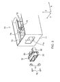
Fig. 3 is an explanatory diagram for explaining a method of attaching the connector to the battery unit. -
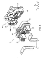
Fig. 4 is a perspective view showing bus bars, the connector, and a rack-side connector. -
Fig. 5 is a perspective view showing a state where the bus bars, the connector, and the rack-side connector are fitted together. -
Fig. 6 is an exploded perspective view showing the connector. -
Fig. 7 is an overall perspective view showing the connector. -
Fig. 8 is an explanatory diagram showing the inside of the connector by cutting the connector. -
Fig. 9 is an explanatory diagram showing the inside of the connector as seen from an angle different fromFig. 8 . -
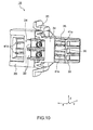
Fig. 10 is an explanatory diagram showing the inside of the connector by cutting the connector at a position different fromFigs. 8 and9 . -
Fig. 11 is an explanatory diagram showing the inside of the connector by cutting the connector at a position different fromFigs. 8 to 10 . -
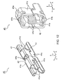
Fig. 12 is an overall perspective view showing a contact and an explanatory diagram showing the contact by cutting it. -
Fig. 13 is an explanatory diagram showing states of sliding a second housing relative to a first housing. -
Fig. 14 is an explanatory diagram conceptually showing states when the connector is attached to the battery unit and when the connector is attached to the rack-side connector. -
Fig. 15 is an explanatory diagram showing conventional plug-in connectors. - Hereinbelow, a connector as one embodiment of this invention will be described with reference to the drawings.
- In the following description, a direction in which a bus bar (connection object) and a rack-side contact (another connection object) are each caused to approach and fitted to a connector is defined as a first direction X, a direction in which a second housing is caused to slide relative to a first housing is defined as a second direction Y, and a direction perpendicular to the first direction X and the second direction Y is defined as a third direction Z. In the following embodiment, a description will be given assuming that the second direction Y is perpendicular to the first direction X. However, it may be configured such that the second direction Y is not perpendicular to the first direction X. Further, in the following embodiment, a description will be given assuming that the fitting direction of the bus bar relative to the connector and the fitting direction of the rack-side contact relative to the connector are set to be parallel to each other. However, they may be set non-parallel to each other.
- A
connector 10 of this embodiment is a connector for a secondary battery. As shown inFigs. 1 to 5 , theconnector 10 is attached to a casing (attaching object) 71 of abattery unit 70 incorporating batteries (secondary batteries) 72 and, when thebattery unit 70 is inserted into a receivingrack 80, theconnector 10 is fitted to a rack-side connector 90 attached to the receivingrack 80, thereby establishing electrical connection betweenbus bars 73 incorporated in thebattery unit 70 and connected to thebatteries 72 and rack-side contacts 91 provided in the rack-side connector 90.Symbol 51 shown inFig. 2 denotes signal lines which are connected to later-described signal contacts (not illustrated). As shown inFig. 2 , eachbus bar 73 comprises abus bar 73b connected to thebatteries 72 and abus bar 73a having one end connected to thebus bar 73b and the other end connected tocontacts 40 of theconnector 10. Thebus bar 73a has a bent L-shape. - As shown in
Figs. 4 to 11 , theconnector 10 comprises afirst housing 20,second housings 30 each attached to thefirst housing 20 so as to be slidable in the second direction Y relative to thefirst housing 20, thecontacts 40 for power supply received incontact receiving portions 60 each formed by thefirst housing 20 and thesecond housing 30, and asignal housing 50 attached to thefirst housing 20 and holding the signal contacts (not illustrated). - The
first housing 20 is formed of an insulating resin. As shown inFig. 3 , thefirst housing 20 is attached to thecasing 71 of thebattery unit 70 usingspacers 74 andbolts 75 in the state where thefirst housing 20 has play (clearance) in the second direction Y and the third direction Z with respect to an attaching opening 71a formed in thecasing 71 so as to be movable in the second direction Y and the third direction Z relative to thecasing 71. - As shown in
Figs. 6 to 11 , thefirst housing 20 integrally has first receivingportions 21 each receiving part of thecontacts 40,first openings 22 each for allowing insertion of the rack-side contact 91 into the first receivingportion 21,slide guide portions 23 supporting later-described attachingspring portions 33 of eachsecond housing 30 in the state where the attachingspring portions 33 are slidable in the second direction Y,first control portions 24 each controlling the position and posture of thecontacts 40 in thecontact receiving portion 60, firstposition restricting portions 25 each restricting the position of thecontacts 40 in the third direction Z, and a signalhousing holding portion 26 holding thesignal housing 50. - As shown in
Figs. 6 and8 , the first receivingportion 21 is open on thesecond housing 30 side and forms thecontact receiving portion 60 jointly with a second receivingportion 31 formed in thesecond housing 30. - As shown in
Figs. 6 to 11 , thefirst control portion 24 extends in the third direction Z from inner walls, defining the first receivingportion 21, of thefirst housing 20 toward the inside of the first receivingportion 21 and, as shown inFigs. 9 and13 , thefirst control portion 24 is interposed between a pair ofconductive members 41 of eachcontact 40 in a region betweensupport portions 41 c andfirst contact portions 41 d of eachcontact 40 in the first direction X. Jointly with asecond control portion 34 formed in thesecond housing 30, thefirst control portion 24 controls the posture (specifically, the posture in the plane defined by the first direction X and the second direction Y) of thecontacts 40 in thecontact receiving portion 60. More specifically, thefirst control portion 24 controls the positional relationship between thefirst opening 22 formed in thefirst housing 20 and thefirst contact portions 41d so that the rack-side contact 91 inserted from thefirst opening 22 can enter between thefirst contact portions 41d regardless of the positional relationship between thefirst housing 20 and thesecond housing 30. Further, thefirst control portion 24 serves as a portion that restricts the insertion position (depth of insertion) of the rack-side contact 91 in the first direction X when the rack-side contact 91 is inserted between thefirst contact portions 41d. - The
second housing 30 is formed of an insulating resin and attached to thefirst housing 20 so as to be slidable in the second direction Y relative to thefirst housing 20. - As shown in
Figs. 6 to 10 , thesecond housing 30 integrally has the second receivingportion 31 receiving part of thecontacts 40, asecond opening 32 for allowing insertion of thebus bar 73 into the second receivingportion 31, the attachingspring portions 33 attached to theslide guide portions 23 of thefirst housing 20, thesecond control portion 34 controlling the position and posture of thecontacts 40 in thecontact receiving portion 60, a secondposition restricting portion 35 restricting the position of thecontacts 40 in the third direction Z, and guideportions 36 serving to guide thebus bar 73 toward thesecond opening 32. - As shown in
Fig. 8 , the second receivingportion 31 is open on thefirst housing 20 side and forms thecontact receiving portion 60 jointly with the first receivingportion 21 formed in thefirst housing 20. - As shown in
Figs. 8 to 11 , thesecond control portion 34 extends in the third direction Z from inner walls, defining the second receivingportion 31, of thesecond housing 30 toward the inside of the second receivingportion 31 and, as shown inFig. 13 , thesecond control portion 34 is interposed between the pair ofconductive members 41 of eachcontact 40 in a region between thesupport portions 41 c andsecond contact portions 41 e of eachcontact 40 in the first direction X. Jointly with thefirst control portion 24 formed in thefirst housing 20, thesecond control portion 34 controls the posture (specifically, the posture in the plane defined by the first direction X and the second direction Y) of thecontacts 40 in thecontact receiving portion 60. More specifically, thesecond control portion 34 controls the positional relationship between thesecond opening 32 formed in thesecond housing 30 and thesecond contact portions 41e so that thebus bar 73 inserted from thesecond opening 32 can enter between thesecond contact portions 41e regardless of the positional relationship between thefirst housing 20 and thesecond housing 30. Further, thesecond control portion 34 serves as a portion that restricts the insertion position (depth of insertion) of thebus bar 73 in the first direction X when thebus bar 73 is inserted between thesecond contact portions 41 e. - The
contact 40 is a socket contact for power supply. As shown inFig. 8 , thecontacts 40 are arranged in a pair in parallel to each other in the third direction Z in each of thecontact receiving portions 60 formed in theconnector 10. Eachcontact 40 is received with play (clearance) with respect to any members including thefirst housing 20 and thesecond housing 30. In other words, eachcontact 40 is not fixed to any members including thefirst housing 20 and thesecond housing 30. - As shown in
Fig. 12 , eachcontact 40 comprises the pair ofconductive members 41 and a biasingmember 42 attached between the pair ofconductive members 41 and biasing the pair ofconductive members 41 in a direction of causing them to approach each other. In this embodiment, as shown inFig. 12 , the biasingmember 42 is in the form of a coil spring. However, its specific configuration is not limited thereto and, for example, it may be formed by an elastic member such as a rubber. - The pair of
conductive members 41 are formed of an inelastic conductive metal (tough pitch copper, copper with a purity of about 99%) and have the same shape. In this embodiment, eachconductive member 41 has a conductivity of 50% or more assuming that the conductivity of pure copper is 100%. - As shown in
Fig. 12 , the pair ofconductive members 41 each have abase portion 41 a arranged spaced apart from that of the otherconductive member 41, an attachingportion 41 b formed at thebase portion 41 a and attached with the biasingmember 42, thesupport portions 41 c extending from thebase portion 41 a toward the otherconductive member 41 and supporting the otherconductive member 41 against a biasing force of the biasingmember 42, and thefirst contact portion 41 d and thesecond contact portion 41 e respectively formed on both sides, in the first direction X, of the attachingportion 41 b (and thesupport portion 41 c). - In this embodiment, as shown in
Fig. 12 , thesupport portions 41c respectively extend along the second direction Y from both sides, in the third direction Z, of thebase portion 41 a and engage with thesupport portions 41 c of the otherconductive member 41 so that the positions of this and otherconductive members 41 are restricted to each other in the first direction X. - As shown in
Fig. 12 , eachcontact 40 is configured such that, in the state where the biasingmember 42 is attached to the pair ofconductive members 41 to thereby engage thesupport portions 41 c of the pair ofconductive members 41 with each other, the three-dimensional structure after the assembly is autonomously maintained. - Each
contact 40 is disposed in the state where thefirst contact portions 41 d face each other in the second direction Y and thesecond contact portions 41 e face each other in the second direction Y, so as to be connected to the rack-side contact 91 by holding the rack-side contact 91 between thefirst contact portions 41d disposed in the first receivingportion 21 and to be connected to thebus bar 73 by holding thebus bar 73 between thesecond contact portions 41e disposed in the second receivingportion 31. - As described before, the position and posture (specifically, the position and posture in the plane defined by the first direction X and the second direction Y) of the
contacts 40 in thecontact receiving portion 60 are controlled by thefirst control portion 24 formed in thefirst housing 20 and thesecond control portion 34 formed in thesecond housing 30 while the position of thecontacts 40 in the third direction Z in thecontact receiving portion 60 is controlled by the firstposition restricting portion 25 formed in thefirst housing 20 and the secondposition restricting portion 35 formed in thesecond housing 30. - As shown in
Fig. 12 , the biasingmember 42 is attached between the attachingportions 41 b respectively formed in the pair ofconductive members 41 and is disposed in a space defined by thebase portions 41 a and thesupport portions 41c respectively formed in the pair ofconductive members 41 forming thecontact 40. - Next, referring mainly to
Fig. 6 , an assembly method of theconnector 10 will be described. - First, the
contacts 40 are inserted into each of thefirst receiving portions 21 of thefirst housing 20. - Herein, the distance between the
first contact portions 41 d facing in the second direction Y is set shorter than the width (width in the second direction Y) of thefirst control portion 24 formed in thefirst housing 20. Consequently, when eachcontact 40 is inserted into thefirst housing 20, the distance between thefirst contact portions 41 d is once increased by thefirst control portion 24. Then, when thecontact 40 is further inserted, thefirst contact portions 41 d ride over thefirst control portion 24 so that the distance between thefirst contact portions 41 d returns to the initial distance. Accordingly, thecontact 40 is prevented from coming off in the first direction X by thefirst control portion 24. - In this manner, the attachment of the
contact 40 to thefirst housing 20 is achieved by the single operation of inserting thecontact 40 into the first receivi ngportion 21. - Then, the
second housings 30 are each inserted into thefirst housing 20 with the attachingspring portion 33 side at the head. - In this event, the attaching
spring portions 33 are brought into contact with thefirst housing 20 so as to be once elastically deformed. Then, when the attachingspring portions 33 are further inserted into thefirst housing 20, the attachingspring portions 33 are elastically restored to engage with theslide guide portions 23 of thefirst housing 20 so that thesecond housing 30 is prevented from coming off thefirst housing 20. - Herein, the distance between the
second contact portions 41e facing in the second direction Y is set equal to or greater than the width (width in the second direction Y) of thesecond control portion 34. Consequently, when thesecond housing 30 is inserted into thefirst housing 20, thesecond contact portions 41 e do not engage with thesecond control portion 34 so that thesecond housing 30 can be smoothly inserted into thefirst housing 20. - In this manner, the attachment of the
second housing 30 to thefirst housing 20 is achieved by the single operation of inserting thesecond housing 30 into thefirst housing 20. - Like the
first control portion 24, the width of thesecond control portion 34 may be set greater than the distance between thesecond contact portions 41e. - Next, referring mainly to
Fig. 14 , a method of attaching theconnector 10 to thebattery unit 70 will be described hereinbelow. - First, with the
second housing 30 side at the head, theconnector 10 is inserted into the attachingopening 71 a formed in thecasing 71, and then the bus bars 73 are each inserted between thesecond contact portions 41 e. - In this event, since each
second housing 30 is attached to thefirst housing 20 so as to be slidable in the second direction Y relative to thefirst housing 20, the position of thesecond housing 30 in the second direction Y is corrected by contact between thebus bar 73 and theguide portions 36 of thesecond housing 30. - Then, with this sliding of the
second housing 30, thecontacts 40 are pushed in the second direction Y by thesecond control portion 34 formed in thesecond housing 30 so that the position of thesecond contact portions 41 e is also corrected in the second direction Y. - In this event, when the
bus bar 73 inserted into theconnector 10 abuts against thesecond control portion 34, the insertion position (insertion depth) of thebus bar 73 in the first direction X is restricted by thesecond control portion 34. - Then, the
first housing 20 is attached to thecasing 71 using thespacers 74 and thebolts 75. - In this state where the
connector 10 is attached to thebattery unit 70, since the bus bars 73 fixed to thecasing 71 are each held between thesecond contact portions 41 e, the positional relationship between thesecond contact portions 41 e (or the second housings 30) and the bus bars 73 (or the casing 71) is almost fixed. On the other hand, in this embodiment, since thefirst housing 20 is provided so as to be slidable in the second direction Y relative to thesecond housings 30 and thecasing 71, thefirst housing 20 can freely move in the second direction Y relative to thecasing 71. - Next, referring mainly to
Fig. 14 , a method of attaching thebattery unit 70 to the receivingrack 80 will be described hereinbelow. - First, with the
connector 10 side at the head, thebattery unit 70 with theconnector 10 is inserted into the receivingrack 80 so that the rack-side contacts 91 are each inserted between thefirst contact portions 41 d. - In this event, since, as shown in
Fig. 4 , a rack-side housing 92 of the rack-side connector 90 is formed withguide portions 92a serving to guide theconnector 10 in the second direction Y and since thefirst housing 20 is attached to thecasing 71 so as to be movable in the second direction Y relative to thecasing 71, thefirst housing 20 is pushed in the second direction Y by theguide portions 92a so that thefirst housing 20 slides relative to thebattery unit 70 to be corrected in position in the second direction Y - In this embodiment, as described above, the
guide portions 92a are formed in the rack-side housing 92. Conversely, guide portions serving to correct the positional relationship in the second direction Y between thefirst housing 20 and the rack-side housing 92 may be formed on thefirst housing 20 side. - Then, with this sliding of the
first housing 20 relative to thebattery unit 70, thecontacts 40 are pushed in the second direction Y by each of thefirst control portions 24 formed in thefirst housing 20 so that the position of thefirst contact portions 41 d is also corrected in the second direction Y. - In this event, when each rack-
side contact 91 inserted into theconnector 10 abuts against thefirst control portion 24, the insertion position of the rack-side contact 91 in the first direction X is restricted by thefirst control portion 24. - In the
connector 10 of this embodiment thus obtained, since thesecond housing 30 is slidably attached to thefirst housing 20 and thecontact 40 is disposed with play in thecontact receiving portion 60 formed by thefirst housing 20 and thesecond housing 30, it is possible to displace thesecond contact portions 41 e of thecontact 40 by thesecond control portion 34 following the sliding movement of thesecond housing 30. Therefore, it is possible to ensure a large floating amount (displacement amount) of thecontact 40 with the simple structure and thus to improve the reliability of connection between thesecond contact portions 41 e and thebus bar 73 by allowing a position offset in the second direction Y between thesecond contact portions 41e and thebus bar 73. - Further, since the
first housing 20 is slidably attached to thesecond housing 30 and, in addition, is attached to thecasing 71 so as to be movable in the second direction Y relative to thecasing 71, even if theconnector 10 is attached to thebattery unit 70 so that the positional relationship between thebus bar 73 and thesecond contact portions 41e is almost fixed, the movability of thefirst housing 20 relative to thecasing 71 of thebattery unit 70 can be maintained. Therefore, it is possible to improve the reliability of connection between thefirst contact portions 41 d and the rack-side contact 91 by allowing a position offset in the second direction Y between thefirst contact portions 41 d and the rack-side contact 91. - Further, since the
contact 40 is received with play in thecontact receiving portion 60 formed by thefirst housing 20 and thesecond housing 30, no additional component, such as an attaching member, is required for attaching thecontact 40 to thefirst housing 20 and thesecond housing 30. Therefore, the number of components is small and thus the workload for assembly can be reduced. - Since the
first control portion 24 that controls the position and posture of thecontact 40 in the first receivingportion 21 is disposed between theconductive members 41, even when thefirst housing 20 slides in either direction as the second direction Y, the position and posture of thecontact 40 on thefirst contact portion 41 d side can be controlled only by thefirst control portion 24 regardless of design of the inner walls, defining the first receivingportion 21 and located around thecontact 40, of thefirst housing 20. Therefore, the degree of design freedom of thefirst housing 20 can be improved. - Likewise, since the
second control portion 34 that controls the position and posture of thecontact 40 in the second receivingportion 31 is disposed between theconductive members 41, even when thesecond housing 30 slides in either direction as the second direction Y, the position and posture of thecontact 40 on thesecond contact portion 41e side can be controlled only by thesecond control portion 34 regardless of design of the inner walls, defining the second receivingportion 31 and located around thecontact 40, of thesecond housing 30. Therefore, the degree of design freedom of thesecond housing 30 can be improved. - Further, since the
first control portion 24 is disposed between theconductive members 41, thefirst control portion 24 serves also as the portion that restricts the insertion position of the rack-side contact 91 in the first direction X when the rack-side contact 91 is inserted into theconnector 10. Consequently, it is not necessary to form a portion, separately from thefirst control portion 24, that restricts the insertion position of the rack-side contact 91. Therefore, the degree of design freedom of thefirst housing 20 can be further improved. - Likewise, since the
second control portion 34 is disposed between theconductive members 41, thesecond control portion 34 serves also as the portion that restricts the insertion position of thebus bar 73 in the first direction X when thebus bar 73 is inserted into theconnector 10. Consequently, it is not necessary to form a portion, separately from thesecond control portion 34, that restricts the insertion position of thebus bar 73. Therefore, the degree of design freedom of thesecond housing 30 can be further improved. - In the above-mentioned embodiment, the description has been given assuming that a connector is a connector to which two different connection objects are fitted from the outside. However, a specific configuration of a connector is not limited thereto. For example, it may be configured such that a single connection object is fitted to a connector from the outside.
- In the above-mentioned embodiment, the description has been given assum ing that a contact has a first contact portion for contact with one connection object and a second contact portion for contact with another connection object. However, in the case where a single connection object is fitted from the outside, a contact may be formed with only one contact portion.
- In the above-mentioned embodiment, the description has been given assuming that a first housing and a second housing each have a control portion that controls the position and posture of a contact in a contact receiving portion. However, the control portion may be provided in only one of the housings.
- In the above-mentioned embodiment, the description has been given assuming that a first housing is movably attached to an attaching object. However, the first housing may be fixed to the attaching object.
- In the above-mentioned embodiment, a contact comprises a pair of conductive members and a biasing member and is configured to contact with a connection object by holding the connection object between the pair of conductive members. However, a specific configuration of a contact is not limited thereto. For example, a contact may be formed by a single conductive member.
- In the above-mentioned embodiment, the description has been given assuming that a contact is entirely received in a contact receiving portion. However, the contact may partially protrude to the outside of the contact receiving portion.
- In the above-mentioned embodiment, the description has been given assuming that a contact is a contact for power supply. However, it may be used as a signal contact.
-
- 10
- connector
- 20
- first housing
- 21
- first receiving portion
- 22
- first opening
- 23
- slide guide portion
- 24
- first control portion
- 25
- first position restricting portion
- 26
- signal housing holding portion
- 30
- second housing
- 31
- second receiving portion
- 32
- second opening
- 33
- attaching spring portion
- 34
- second control portion
- 35
- second position restricting portion
- 36
- guide portion
- 40
- contact
- 41
- conductive member
- 41a
- base portion
- 41b
- attaching portion
- 41c
- support portion
- 41d
- first contact portion
- 41e
- second contact portion
- 42
- biasing member
- 50
- signal housing
- 51
- signal line
- 60
- contact receiving portion
- 70
- battery unit
- 71
- casing (attaching object)
- 71a
- attaching opening
- 72
- battery
- 73
- bus bar (connection object)
- 74
- spacer
- 75
- bolt
- 80
- receiving rack
- 90
- rack-side connector
- 91
- rack-side contact (another connection object)
- 92
- rack-side housing
- 92a
- guide portion
- X
- first direction
- Y
- second direction
- Z
- third direction
Claims (16)
- A connector comprising:a first housing,a second housing attached to the first housing and forming a contact receiving portion jointly with the first housing, anda contact at least partially received in the contact receiving portion,wherein the second housing is attached to the first housing so as to be movable in a predetermined direction relative to the first housing, andwherein the contact is received in the contact receiving portion in a state where the contact is not fixed to the first housing or the second housing so as to be movable relative to the first housing and the second housing.
- The connector according to claim 1, wherein the contact comprises a second contact portion disposed on the second housing side and adapted to contact with a connection object.
- The connector according to claim 2, wherein the contact further comprises a first contact portion disposed on the first housing side and adapted to contact with another connection object.
- The connector according to any one of claims 1 to 3, wherein the second housing comprises a second control portion that controls a position and posture of the contact in the contact receiving portion and that pushes the contact when the first housing and the second housing move relative to each other.
- The connector according to any one of claims 1 to 4, wherein the first housing comprises a first control portion that controls a position and posture of the contact in the contact receiving portion and that pushes the contact when the first housing and the second housing move relative to each other.
- The connector according to any one of claims 1 to 5,
wherein the contact comprises a pair of conductive members facing each other and a biasing member provided between the pair of conductive members and biasing the pair of conductive members in a direction of causing them to approach each other, and
wherein the contact is adapted to hold the connection object between the pair of conductive members biased by the biasing member. - The connector according to claim 6, wherein the second control portion of the second housing is interposed between the pair of conductive members.
- The connector according to any one of claims 1 to 7,
wherein the contact comprises a pair of conductive members facing each other and a biasing member provided between the pair of conductive members and biasing the pair of conductive members in a direction of causing them to approach each other, and
wherein the contact is adapted to hold the another connection object between the pair of conductive members biased by the biasing member. - The connector according to claim 8, wherein the first control portion of the first housing is interposed between the pair of conductive members.
- The connector according to any one of claims 1 to 9, wherein the second housing comprises a second position restricting portion that restricts a position of the contact in a direction perpendicular to a direction of fitting to the connection object and to a direction in which the first housing relatively moves.
- The connector according to any one of claims 1 to 10, wherein the first housing comprises a first position restricting portion that restricts a position of the contact in a direction perpendicular to a direction of fitting to the connection object and to a direction in which the second housing relatively moves.
- The connector according to any one of claims 1 to 11, wherein the second housing is attached to the first housing so as to be movable relative to the first housing in a direction perpendicular to a direction of fitting to the connection object.
- A connector device comprising the connector according to any one of claims 1 to 12 and an attaching object to which the connector is attached,
wherein the first housing is attached to the attaching object so as to be movable relative to the attaching object. - A battery unit comprising the connector according to any one of claims 1 to 12, an attaching object to which the connector is attached, and the connection object,
wherein the connection object is a bus bar. - The battery unit according to claim 14, further comprising another bus bar,
wherein the bus bar is connected to the other bus bar and to the contact of the connector. - The battery unit according to claim 14 or 15, wherein the bus bar comprises a bent shape.
Applications Claiming Priority (2)
| Application Number | Priority Date | Filing Date | Title |
|---|---|---|---|
| JP2011141457A JP5041563B1 (en) | 2011-06-27 | 2011-06-27 | Connector, connector device and battery unit |
| PCT/JP2011/076164 WO2013001671A1 (en) | 2011-06-27 | 2011-11-14 | Connector, connector device, and battery unit |
Publications (3)
| Publication Number | Publication Date |
|---|---|
| EP2696447A1 true EP2696447A1 (en) | 2014-02-12 |
| EP2696447A4 EP2696447A4 (en) | 2014-10-22 |
| EP2696447B1 EP2696447B1 (en) | 2018-09-12 |
Family
ID=47087585
Family Applications (1)
| Application Number | Title | Priority Date | Filing Date |
|---|---|---|---|
| EP11868842.3A Active EP2696447B1 (en) | 2011-06-27 | 2011-11-14 | Connector, connector device, and battery unit |
Country Status (6)
| Country | Link |
|---|---|
| US (1) | US9172168B2 (en) |
| EP (1) | EP2696447B1 (en) |
| JP (1) | JP5041563B1 (en) |
| CN (1) | CN103503244B (en) |
| TW (1) | TWI501490B (en) |
| WO (1) | WO2013001671A1 (en) |
Cited By (1)
| Publication number | Priority date | Publication date | Assignee | Title |
|---|---|---|---|---|
| US12334679B2 (en) | 2020-05-12 | 2025-06-17 | Phoenix Contact Gmbh & Co. Kg | Connection unit, connection arrangement and electronic device |
Families Citing this family (12)
| Publication number | Priority date | Publication date | Assignee | Title |
|---|---|---|---|---|
| JP6064230B2 (en) * | 2014-05-16 | 2017-01-25 | ヒロセ電機株式会社 | Electrical connection device |
| US9853277B2 (en) * | 2015-06-19 | 2017-12-26 | Ford Global Technologies, Llc | Bus bar assembly including biased bus bar |
| DE102016103839B4 (en) | 2016-03-03 | 2018-09-20 | Johnson Controls Advanced Power Solutions Gmbh | Signal connector for a battery module |
| JP6840542B2 (en) | 2017-01-04 | 2021-03-10 | 日本航空電子工業株式会社 | connector |
| US11056807B2 (en) | 2017-04-14 | 2021-07-06 | Amphenol Corporation | Float connector for interconnecting printed circuit boards |
| JP6480500B2 (en) | 2017-04-28 | 2019-03-13 | 日本航空電子工業株式会社 | connector |
| JP6965990B2 (en) * | 2018-04-26 | 2021-11-10 | 住友電装株式会社 | connector |
| JP7042403B2 (en) * | 2018-12-28 | 2022-03-28 | 住友電装株式会社 | Joint connector |
| US12166314B2 (en) * | 2021-07-27 | 2024-12-10 | Dell Products L.P. | Battery connector in an information handling system |
| US12191614B2 (en) * | 2021-08-26 | 2025-01-07 | Te Connectivity Brasil Industria De Eletronicos Ltda. | Header power connector |
| CN118352844A (en) * | 2023-01-13 | 2024-07-16 | 莫列斯有限公司 | Electric connection device |
| US20260003413A1 (en) * | 2024-06-26 | 2026-01-01 | Dell Products L.P. | Information handling system battery connector detection for system reset |
Family Cites Families (14)
| Publication number | Priority date | Publication date | Assignee | Title |
|---|---|---|---|---|
| US3427419A (en) * | 1966-03-31 | 1969-02-11 | Westinghouse Electric Corp | Disconnecting contact assembly for electrical apparatus |
| GB2064884B (en) * | 1979-12-04 | 1983-12-07 | Mitsubishi Electric Corp | Electrical contact device |
| JPS62131333A (en) | 1985-12-04 | 1987-06-13 | Hitachi Ltd | Information search method |
| JPH0447856Y2 (en) * | 1986-02-13 | 1992-11-11 | ||
| JPH033991Y2 (en) * | 1987-11-20 | 1991-01-31 | ||
| US4878862A (en) * | 1988-12-05 | 1989-11-07 | Amp Incorporated | Connector for mating two bus bars |
| FR2693843B1 (en) * | 1992-07-16 | 1994-08-19 | Alsthom Gec | Skewer clamp. |
| US5931688A (en) * | 1996-09-16 | 1999-08-03 | The Whitaker Company | Self docketing electrical connector assembly |
| JP2003346940A (en) * | 2002-05-27 | 2003-12-05 | Nec Corp | Power supply relay terminal block and power supply unit having power supply relay terminal block |
| JP4613179B2 (en) | 2007-02-09 | 2011-01-12 | 日本航空電子工業株式会社 | Card edge connector |
| US7976317B2 (en) * | 2007-12-04 | 2011-07-12 | Molex Incorporated | Low profile modular electrical connectors and systems |
| JP5334997B2 (en) * | 2008-01-17 | 2013-11-06 | アンフェノル・コーポレーション | Interposer assembly and method |
| JP2009218063A (en) * | 2008-03-10 | 2009-09-24 | Mitsutoshi Watanabe | Flat connector for electric power supply |
| JP2011060732A (en) * | 2009-09-14 | 2011-03-24 | Japan Aviation Electronics Industry Ltd | Connector |
-
2011
- 2011-06-27 JP JP2011141457A patent/JP5041563B1/en active Active
- 2011-11-14 WO PCT/JP2011/076164 patent/WO2013001671A1/en not_active Ceased
- 2011-11-14 US US14/111,493 patent/US9172168B2/en active Active
- 2011-11-14 EP EP11868842.3A patent/EP2696447B1/en active Active
- 2011-11-14 CN CN201180070149.1A patent/CN103503244B/en active Active
-
2012
- 2012-06-25 TW TW101122570A patent/TWI501490B/en active
Cited By (1)
| Publication number | Priority date | Publication date | Assignee | Title |
|---|---|---|---|---|
| US12334679B2 (en) | 2020-05-12 | 2025-06-17 | Phoenix Contact Gmbh & Co. Kg | Connection unit, connection arrangement and electronic device |
Also Published As
| Publication number | Publication date |
|---|---|
| TW201312882A (en) | 2013-03-16 |
| CN103503244A (en) | 2014-01-08 |
| US9172168B2 (en) | 2015-10-27 |
| US20140080339A1 (en) | 2014-03-20 |
| JP2013008612A (en) | 2013-01-10 |
| EP2696447A4 (en) | 2014-10-22 |
| JP5041563B1 (en) | 2012-10-03 |
| CN103503244B (en) | 2016-08-24 |
| WO2013001671A1 (en) | 2013-01-03 |
| TWI501490B (en) | 2015-09-21 |
| EP2696447B1 (en) | 2018-09-12 |
Similar Documents
| Publication | Publication Date | Title |
|---|---|---|
| EP2696447B1 (en) | Connector, connector device, and battery unit | |
| US9570722B2 (en) | Power storage device | |
| US9455515B2 (en) | Contact, connector, and connecting device | |
| US9236698B2 (en) | Contact and connector having a pair of conductive members and a biasing member biasing the pair of conductive members toward each other | |
| US8747146B2 (en) | Electrical connector having connector position assurance | |
| EP2846411A1 (en) | Contact, connector, and connecting device | |
| EP3093903A1 (en) | Connector for battery unit, and battery unit provided with same | |
| US20140370731A1 (en) | Electric coupling element | |
| US20110111648A1 (en) | Board connector | |
| CN107681355B (en) | Electric connector and push-pull type power distribution cabinet | |
| EP2884597B1 (en) | Lever actuated electrical center assembly | |
| US7713069B2 (en) | Electrical connector and assembly |
Legal Events
| Date | Code | Title | Description |
|---|---|---|---|
| PUAI | Public reference made under article 153(3) epc to a published international application that has entered the european phase |
Free format text: ORIGINAL CODE: 0009012 |
|
| 17P | Request for examination filed |
Effective date: 20131105 |
|
| AK | Designated contracting states |
Kind code of ref document: A1 Designated state(s): AL AT BE BG CH CY CZ DE DK EE ES FI FR GB GR HR HU IE IS IT LI LT LU LV MC MK MT NL NO PL PT RO RS SE SI SK SM TR |
|
| DAX | Request for extension of the european patent (deleted) | ||
| A4 | Supplementary search report drawn up and despatched |
Effective date: 20140923 |
|
| RIC1 | Information provided on ipc code assigned before grant |
Ipc: H01R 4/40 20060101ALN20140917BHEP Ipc: H01R 13/15 20060101ALI20140917BHEP Ipc: H01R 13/514 20060101ALI20140917BHEP Ipc: H01R 4/48 20060101ALN20140917BHEP Ipc: H01R 13/631 20060101AFI20140917BHEP |
|
| 17Q | First examination report despatched |
Effective date: 20150521 |
|
| STAA | Information on the status of an ep patent application or granted ep patent |
Free format text: STATUS: EXAMINATION IS IN PROGRESS |
|
| GRAP | Despatch of communication of intention to grant a patent |
Free format text: ORIGINAL CODE: EPIDOSNIGR1 |
|
| STAA | Information on the status of an ep patent application or granted ep patent |
Free format text: STATUS: GRANT OF PATENT IS INTENDED |
|
| RIC1 | Information provided on ipc code assigned before grant |
Ipc: H01R 4/48 20060101ALN20180123BHEP Ipc: H01R 13/631 20060101AFI20180123BHEP Ipc: H01R 13/15 20060101ALI20180123BHEP Ipc: H01R 4/40 20060101ALN20180123BHEP Ipc: H01R 13/514 20060101ALI20180123BHEP |
|
| INTG | Intention to grant announced |
Effective date: 20180207 |
|
| GRAJ | Information related to disapproval of communication of intention to grant by the applicant or resumption of examination proceedings by the epo deleted |
Free format text: ORIGINAL CODE: EPIDOSDIGR1 |
|
| STAA | Information on the status of an ep patent application or granted ep patent |
Free format text: STATUS: EXAMINATION IS IN PROGRESS |
|
| INTC | Intention to grant announced (deleted) | ||
| GRAR | Information related to intention to grant a patent recorded |
Free format text: ORIGINAL CODE: EPIDOSNIGR71 |
|
| GRAS | Grant fee paid |
Free format text: ORIGINAL CODE: EPIDOSNIGR3 |
|
| STAA | Information on the status of an ep patent application or granted ep patent |
Free format text: STATUS: GRANT OF PATENT IS INTENDED |
|
| GRAA | (expected) grant |
Free format text: ORIGINAL CODE: 0009210 |
|
| STAA | Information on the status of an ep patent application or granted ep patent |
Free format text: STATUS: THE PATENT HAS BEEN GRANTED |
|
| RIC1 | Information provided on ipc code assigned before grant |
Ipc: H01R 13/15 20060101ALI20180710BHEP Ipc: H01R 13/631 20060101AFI20180710BHEP Ipc: H01R 13/514 20060101ALI20180710BHEP Ipc: H01R 4/48 20060101ALN20180710BHEP Ipc: H01R 4/40 20060101ALN20180710BHEP |
|
| INTG | Intention to grant announced |
Effective date: 20180801 |
|
| AK | Designated contracting states |
Kind code of ref document: B1 Designated state(s): AL AT BE BG CH CY CZ DE DK EE ES FI FR GB GR HR HU IE IS IT LI LT LU LV MC MK MT NL NO PL PT RO RS SE SI SK SM TR |
|
| REG | Reference to a national code |
Ref country code: GB Ref legal event code: FG4D |
|
| REG | Reference to a national code |
Ref country code: CH Ref legal event code: EP |
|
| REG | Reference to a national code |
Ref country code: IE Ref legal event code: FG4D |
|
| REG | Reference to a national code |
Ref country code: DE Ref legal event code: R096 Ref document number: 602011052071 Country of ref document: DE |
|
| REG | Reference to a national code |
Ref country code: AT Ref legal event code: REF Ref document number: 1041694 Country of ref document: AT Kind code of ref document: T Effective date: 20181015 |
|
| REG | Reference to a national code |
Ref country code: NL Ref legal event code: MP Effective date: 20180912 |
|
| REG | Reference to a national code |
Ref country code: LT Ref legal event code: MG4D |
|
| PG25 | Lapsed in a contracting state [announced via postgrant information from national office to epo] |
Ref country code: LT Free format text: LAPSE BECAUSE OF FAILURE TO SUBMIT A TRANSLATION OF THE DESCRIPTION OR TO PAY THE FEE WITHIN THE PRESCRIBED TIME-LIMIT Effective date: 20180912 Ref country code: FI Free format text: LAPSE BECAUSE OF FAILURE TO SUBMIT A TRANSLATION OF THE DESCRIPTION OR TO PAY THE FEE WITHIN THE PRESCRIBED TIME-LIMIT Effective date: 20180912 Ref country code: RS Free format text: LAPSE BECAUSE OF FAILURE TO SUBMIT A TRANSLATION OF THE DESCRIPTION OR TO PAY THE FEE WITHIN THE PRESCRIBED TIME-LIMIT Effective date: 20180912 Ref country code: GR Free format text: LAPSE BECAUSE OF FAILURE TO SUBMIT A TRANSLATION OF THE DESCRIPTION OR TO PAY THE FEE WITHIN THE PRESCRIBED TIME-LIMIT Effective date: 20181213 Ref country code: NO Free format text: LAPSE BECAUSE OF FAILURE TO SUBMIT A TRANSLATION OF THE DESCRIPTION OR TO PAY THE FEE WITHIN THE PRESCRIBED TIME-LIMIT Effective date: 20181212 Ref country code: BG Free format text: LAPSE BECAUSE OF FAILURE TO SUBMIT A TRANSLATION OF THE DESCRIPTION OR TO PAY THE FEE WITHIN THE PRESCRIBED TIME-LIMIT Effective date: 20181212 Ref country code: SE Free format text: LAPSE BECAUSE OF FAILURE TO SUBMIT A TRANSLATION OF THE DESCRIPTION OR TO PAY THE FEE WITHIN THE PRESCRIBED TIME-LIMIT Effective date: 20180912 |
|
| PG25 | Lapsed in a contracting state [announced via postgrant information from national office to epo] |
Ref country code: HR Free format text: LAPSE BECAUSE OF FAILURE TO SUBMIT A TRANSLATION OF THE DESCRIPTION OR TO PAY THE FEE WITHIN THE PRESCRIBED TIME-LIMIT Effective date: 20180912 Ref country code: LV Free format text: LAPSE BECAUSE OF FAILURE TO SUBMIT A TRANSLATION OF THE DESCRIPTION OR TO PAY THE FEE WITHIN THE PRESCRIBED TIME-LIMIT Effective date: 20180912 Ref country code: AL Free format text: LAPSE BECAUSE OF FAILURE TO SUBMIT A TRANSLATION OF THE DESCRIPTION OR TO PAY THE FEE WITHIN THE PRESCRIBED TIME-LIMIT Effective date: 20180912 |
|
| REG | Reference to a national code |
Ref country code: AT Ref legal event code: MK05 Ref document number: 1041694 Country of ref document: AT Kind code of ref document: T Effective date: 20180912 |
|
| PG25 | Lapsed in a contracting state [announced via postgrant information from national office to epo] |
Ref country code: RO Free format text: LAPSE BECAUSE OF FAILURE TO SUBMIT A TRANSLATION OF THE DESCRIPTION OR TO PAY THE FEE WITHIN THE PRESCRIBED TIME-LIMIT Effective date: 20180912 Ref country code: CZ Free format text: LAPSE BECAUSE OF FAILURE TO SUBMIT A TRANSLATION OF THE DESCRIPTION OR TO PAY THE FEE WITHIN THE PRESCRIBED TIME-LIMIT Effective date: 20180912 Ref country code: ES Free format text: LAPSE BECAUSE OF FAILURE TO SUBMIT A TRANSLATION OF THE DESCRIPTION OR TO PAY THE FEE WITHIN THE PRESCRIBED TIME-LIMIT Effective date: 20180912 Ref country code: IS Free format text: LAPSE BECAUSE OF FAILURE TO SUBMIT A TRANSLATION OF THE DESCRIPTION OR TO PAY THE FEE WITHIN THE PRESCRIBED TIME-LIMIT Effective date: 20190112 Ref country code: PL Free format text: LAPSE BECAUSE OF FAILURE TO SUBMIT A TRANSLATION OF THE DESCRIPTION OR TO PAY THE FEE WITHIN THE PRESCRIBED TIME-LIMIT Effective date: 20180912 Ref country code: NL Free format text: LAPSE BECAUSE OF FAILURE TO SUBMIT A TRANSLATION OF THE DESCRIPTION OR TO PAY THE FEE WITHIN THE PRESCRIBED TIME-LIMIT Effective date: 20180912 Ref country code: IT Free format text: LAPSE BECAUSE OF FAILURE TO SUBMIT A TRANSLATION OF THE DESCRIPTION OR TO PAY THE FEE WITHIN THE PRESCRIBED TIME-LIMIT Effective date: 20180912 Ref country code: EE Free format text: LAPSE BECAUSE OF FAILURE TO SUBMIT A TRANSLATION OF THE DESCRIPTION OR TO PAY THE FEE WITHIN THE PRESCRIBED TIME-LIMIT Effective date: 20180912 Ref country code: AT Free format text: LAPSE BECAUSE OF FAILURE TO SUBMIT A TRANSLATION OF THE DESCRIPTION OR TO PAY THE FEE WITHIN THE PRESCRIBED TIME-LIMIT Effective date: 20180912 |
|
| PG25 | Lapsed in a contracting state [announced via postgrant information from national office to epo] |
Ref country code: SM Free format text: LAPSE BECAUSE OF FAILURE TO SUBMIT A TRANSLATION OF THE DESCRIPTION OR TO PAY THE FEE WITHIN THE PRESCRIBED TIME-LIMIT Effective date: 20180912 Ref country code: SK Free format text: LAPSE BECAUSE OF FAILURE TO SUBMIT A TRANSLATION OF THE DESCRIPTION OR TO PAY THE FEE WITHIN THE PRESCRIBED TIME-LIMIT Effective date: 20180912 Ref country code: PT Free format text: LAPSE BECAUSE OF FAILURE TO SUBMIT A TRANSLATION OF THE DESCRIPTION OR TO PAY THE FEE WITHIN THE PRESCRIBED TIME-LIMIT Effective date: 20190112 |
|
| REG | Reference to a national code |
Ref country code: DE Ref legal event code: R097 Ref document number: 602011052071 Country of ref document: DE |
|
| REG | Reference to a national code |
Ref country code: CH Ref legal event code: PL |
|
| PLBE | No opposition filed within time limit |
Free format text: ORIGINAL CODE: 0009261 |
|
| STAA | Information on the status of an ep patent application or granted ep patent |
Free format text: STATUS: NO OPPOSITION FILED WITHIN TIME LIMIT |
|
| PG25 | Lapsed in a contracting state [announced via postgrant information from national office to epo] |
Ref country code: LU Free format text: LAPSE BECAUSE OF NON-PAYMENT OF DUE FEES Effective date: 20181114 Ref country code: DK Free format text: LAPSE BECAUSE OF FAILURE TO SUBMIT A TRANSLATION OF THE DESCRIPTION OR TO PAY THE FEE WITHIN THE PRESCRIBED TIME-LIMIT Effective date: 20180912 Ref country code: MC Free format text: LAPSE BECAUSE OF FAILURE TO SUBMIT A TRANSLATION OF THE DESCRIPTION OR TO PAY THE FEE WITHIN THE PRESCRIBED TIME-LIMIT Effective date: 20180912 |
|
| REG | Reference to a national code |
Ref country code: BE Ref legal event code: MM Effective date: 20181130 |
|
| 26N | No opposition filed |
Effective date: 20190613 |
|
| REG | Reference to a national code |
Ref country code: IE Ref legal event code: MM4A |
|
| GBPC | Gb: european patent ceased through non-payment of renewal fee |
Effective date: 20181212 |
|
| PG25 | Lapsed in a contracting state [announced via postgrant information from national office to epo] |
Ref country code: CH Free format text: LAPSE BECAUSE OF NON-PAYMENT OF DUE FEES Effective date: 20181130 Ref country code: SI Free format text: LAPSE BECAUSE OF FAILURE TO SUBMIT A TRANSLATION OF THE DESCRIPTION OR TO PAY THE FEE WITHIN THE PRESCRIBED TIME-LIMIT Effective date: 20180912 Ref country code: LI Free format text: LAPSE BECAUSE OF NON-PAYMENT OF DUE FEES Effective date: 20181130 |
|
| PG25 | Lapsed in a contracting state [announced via postgrant information from national office to epo] |
Ref country code: FR Free format text: LAPSE BECAUSE OF NON-PAYMENT OF DUE FEES Effective date: 20181130 Ref country code: IE Free format text: LAPSE BECAUSE OF NON-PAYMENT OF DUE FEES Effective date: 20181114 |
|
| PG25 | Lapsed in a contracting state [announced via postgrant information from national office to epo] |
Ref country code: BE Free format text: LAPSE BECAUSE OF NON-PAYMENT OF DUE FEES Effective date: 20181130 |
|
| PG25 | Lapsed in a contracting state [announced via postgrant information from national office to epo] |
Ref country code: GB Free format text: LAPSE BECAUSE OF NON-PAYMENT OF DUE FEES Effective date: 20181212 |
|
| PG25 | Lapsed in a contracting state [announced via postgrant information from national office to epo] |
Ref country code: MT Free format text: LAPSE BECAUSE OF NON-PAYMENT OF DUE FEES Effective date: 20181114 |
|
| PG25 | Lapsed in a contracting state [announced via postgrant information from national office to epo] |
Ref country code: TR Free format text: LAPSE BECAUSE OF FAILURE TO SUBMIT A TRANSLATION OF THE DESCRIPTION OR TO PAY THE FEE WITHIN THE PRESCRIBED TIME-LIMIT Effective date: 20180912 |
|
| PG25 | Lapsed in a contracting state [announced via postgrant information from national office to epo] |
Ref country code: CY Free format text: LAPSE BECAUSE OF FAILURE TO SUBMIT A TRANSLATION OF THE DESCRIPTION OR TO PAY THE FEE WITHIN THE PRESCRIBED TIME-LIMIT Effective date: 20180912 Ref country code: HU Free format text: LAPSE BECAUSE OF FAILURE TO SUBMIT A TRANSLATION OF THE DESCRIPTION OR TO PAY THE FEE WITHIN THE PRESCRIBED TIME-LIMIT; INVALID AB INITIO Effective date: 20111114 Ref country code: MK Free format text: LAPSE BECAUSE OF NON-PAYMENT OF DUE FEES Effective date: 20180912 |
|
| PGFP | Annual fee paid to national office [announced via postgrant information from national office to epo] |
Ref country code: DE Payment date: 20250930 Year of fee payment: 15 |