EP2696228A1 - Optical connector - Google Patents
Optical connector Download PDFInfo
- Publication number
- EP2696228A1 EP2696228A1 EP12767593.2A EP12767593A EP2696228A1 EP 2696228 A1 EP2696228 A1 EP 2696228A1 EP 12767593 A EP12767593 A EP 12767593A EP 2696228 A1 EP2696228 A1 EP 2696228A1
- Authority
- EP
- European Patent Office
- Prior art keywords
- flange portion
- locking
- optical fiber
- boot
- protrusion
- Prior art date
- Legal status (The legal status is an assumption and is not a legal conclusion. Google has not performed a legal analysis and makes no representation as to the accuracy of the status listed.)
- Withdrawn
Links
- 230000003287 optical effect Effects 0.000 title claims abstract description 43
- 239000013307 optical fiber Substances 0.000 claims abstract description 68
- 238000002788 crimping Methods 0.000 claims abstract description 56
- 230000001681 protective effect Effects 0.000 claims abstract description 14
- 238000005452 bending Methods 0.000 description 6
- 239000000463 material Substances 0.000 description 6
- 238000000926 separation method Methods 0.000 description 5
- 239000000853 adhesive Substances 0.000 description 2
- 230000001070 adhesive effect Effects 0.000 description 2
- 230000008878 coupling Effects 0.000 description 2
- 238000010168 coupling process Methods 0.000 description 2
- 238000005859 coupling reaction Methods 0.000 description 2
- 230000005489 elastic deformation Effects 0.000 description 1
- 238000009434 installation Methods 0.000 description 1
- 238000000034 method Methods 0.000 description 1
- 238000012986 modification Methods 0.000 description 1
- 230000004048 modification Effects 0.000 description 1
- 230000002093 peripheral effect Effects 0.000 description 1
- 229920005989 resin Polymers 0.000 description 1
- 239000011347 resin Substances 0.000 description 1
- 239000007779 soft material Substances 0.000 description 1
- 229920003051 synthetic elastomer Polymers 0.000 description 1
- 229920003002 synthetic resin Polymers 0.000 description 1
- 239000000057 synthetic resin Substances 0.000 description 1
- 239000005061 synthetic rubber Substances 0.000 description 1
Images



Classifications
-
- G—PHYSICS
- G02—OPTICS
- G02B—OPTICAL ELEMENTS, SYSTEMS OR APPARATUS
- G02B6/00—Light guides; Structural details of arrangements comprising light guides and other optical elements, e.g. couplings
- G02B6/24—Coupling light guides
- G02B6/36—Mechanical coupling means
-
- G—PHYSICS
- G02—OPTICS
- G02B—OPTICAL ELEMENTS, SYSTEMS OR APPARATUS
- G02B6/00—Light guides; Structural details of arrangements comprising light guides and other optical elements, e.g. couplings
- G02B6/24—Coupling light guides
- G02B6/36—Mechanical coupling means
- G02B6/38—Mechanical coupling means having fibre to fibre mating means
- G02B6/3807—Dismountable connectors, i.e. comprising plugs
- G02B6/3887—Anchoring optical cables to connector housings, e.g. strain relief features
- G02B6/3888—Protection from over-extension or over-compression
-
- G—PHYSICS
- G02—OPTICS
- G02B—OPTICAL ELEMENTS, SYSTEMS OR APPARATUS
- G02B6/00—Light guides; Structural details of arrangements comprising light guides and other optical elements, e.g. couplings
- G02B6/24—Coupling light guides
- G02B6/36—Mechanical coupling means
- G02B6/38—Mechanical coupling means having fibre to fibre mating means
-
- G—PHYSICS
- G02—OPTICS
- G02B—OPTICAL ELEMENTS, SYSTEMS OR APPARATUS
- G02B6/00—Light guides; Structural details of arrangements comprising light guides and other optical elements, e.g. couplings
- G02B6/24—Coupling light guides
- G02B6/36—Mechanical coupling means
- G02B6/38—Mechanical coupling means having fibre to fibre mating means
- G02B6/3807—Dismountable connectors, i.e. comprising plugs
- G02B6/3833—Details of mounting fibres in ferrules; Assembly methods; Manufacture
- G02B6/3855—Details of mounting fibres in ferrules; Assembly methods; Manufacture characterised by the method of anchoring or fixing the fibre within the ferrule
- G02B6/3857—Crimping, i.e. involving plastic deformation
-
- G—PHYSICS
- G02—OPTICS
- G02B—OPTICAL ELEMENTS, SYSTEMS OR APPARATUS
- G02B6/00—Light guides; Structural details of arrangements comprising light guides and other optical elements, e.g. couplings
- G02B6/24—Coupling light guides
- G02B6/36—Mechanical coupling means
- G02B6/38—Mechanical coupling means having fibre to fibre mating means
- G02B6/3807—Dismountable connectors, i.e. comprising plugs
- G02B6/3873—Connectors using guide surfaces for aligning ferrule ends, e.g. tubes, sleeves, V-grooves, rods, pins, balls
- G02B6/3874—Connectors using guide surfaces for aligning ferrule ends, e.g. tubes, sleeves, V-grooves, rods, pins, balls using tubes, sleeves to align ferrules
- G02B6/3878—Connectors using guide surfaces for aligning ferrule ends, e.g. tubes, sleeves, V-grooves, rods, pins, balls using tubes, sleeves to align ferrules comprising a plurality of ferrules, branching and break-out means
-
- G—PHYSICS
- G02—OPTICS
- G02B—OPTICAL ELEMENTS, SYSTEMS OR APPARATUS
- G02B6/00—Light guides; Structural details of arrangements comprising light guides and other optical elements, e.g. couplings
- G02B6/24—Coupling light guides
- G02B6/36—Mechanical coupling means
- G02B6/38—Mechanical coupling means having fibre to fibre mating means
- G02B6/3807—Dismountable connectors, i.e. comprising plugs
- G02B6/3887—Anchoring optical cables to connector housings, e.g. strain relief features
- G02B6/38875—Protection from bending or twisting
Definitions
- the present invention relates to an optical connector.
- such an optical connector 501 includes a stop ring 507 having a through-hole 503 formed therein so that an optical fiber 505 is disposed in the through-hole 503; a crimping ring 511 disposed around an optical fiber cable 509 for crimping the stop ring 507 and the optical fiber cable 509; a ferrule 513 disposed on a distal end of the optical fiber of the optical fiber cable 509; a spring (not shown) disposed between the ferrule 513 and the stop ring 507; a plug frame 517 fitted to the stop ring 507; a grip 519 fitted to the plug frame 517; and a boot 521 for covering portions of the crimping ring 511 and the optical fiber cable 509.
- the optical fiber cable 509 is extended through the boot 521, the crimping ring 511 and the stop ring in this order.
- the ferrule 513 is fixed on the optical fiber 505 exposed by removing a sheath 523 or a tension-resistance body 525.
- the stop ring 507 is crimped by applying a pressure from the periphery thereof using a pressing tool or the like, while the tension-resistance body 525 is sandwiched between the stop ring 507 and the crimping ring 511.
- the grip 519 is fitted to the plug frame 517, and also the boot 521 is disposed to cover a portion of the stop ring 507, the crimping ring 511 and a portion of the optical fiber cable 509, thereby completing the optical fiber cable 509 having the optical connector.
- the boot 521 is fixed on the crimping ring 511 after crimping by press-fitting or adhesives. Therefore, in a case of fixation by press-ftting, there is a risk of separation of the boot due to inadvertent pulling of the boot or loosening of the optical fiber cable bending. Further, in a case of fixation by adhesives, there is a risk of increasing adhesion operation man-hours, material costs or the like, in addition to the same risk as those in the press-fitting fixation.
- the present invention has been made keeping in mind the above problems, and an object thereof is to provide an optical connector in which separation of a boot due to inadvertent pulling of the boot or loosening of an optical fiber cable bending can be prevented without increasing operation man-hours or material costs.
- the sandwiching flange portion of the crimping sleeve can press the locking flange portion of the boot before the boot locking protrusion is abutted to the rear wall inner surface, and as result, pulling out of the locking flange portion can be prevented by both sandwiching and locking actions.
- optical connector 11 is coupled to a corresponding optical connector, not shown, so that distal ends of optical fibers 15, which are core wires of optical fiber cables 13, are abutted and connected to each other. Accordingly, optical fibers, for example, for a vehicle LAN or the like are connected to each other.
- the optical connector 11 includes a housing 17 for receiving a ferrule 19 connected to a distal end of the optical fiber of the optical fiber cable 13; a crimping sleeve 21 including a tubular portion 53 adapted to allow the optical fiber 15 to be inserted therethrough and also adapted to be inserted through a sleeve through-hole 51 formed in a rear wall 49 of the housing 17, and a sandwiching flange portion 55 continued from the tubular portion 53 and facing an rear wall inner surface 59 of the housing 17; a crimping ring 29 for fixing a sheath 35 of the optical fiber cable 13 sheathed on an outer circumference of the tubular portion 53; and a boot 23 including a protective portion for covering outer circumferences of the optical fiber cable 13 and the crimping ring 29, and a locking flange portion 65 continued from the protective portion and sandwiched between the sandwiching flange portion 55 and the rear wall inner surface 59.
- the optical fiber cable 13, the ferrule 19, the crimping sleeve 21, the crimping ring 29 and the boot 23 constitute a ferrule assembly 31.
- the housing 17 made of a synthetic resin has, on a front side thereof, coupling opening portions 33 intended to be coupled with the corresponding optical connector, not shown.
- a pair of ferrules 19 are received inside the coupling opening portions 33.
- the optical fiber 15 exposed by removing the sheath 35 and a tension-resistance body, not shown, from the optical fiber cable 13 is inserted and fixed in each of the ferrules 19.
- These ferrules 19 are movably received in the housing 17 in an axial direction thereof, and are elastically urged forward by a leaf spring 37 received in the housing 17.
- the leaf spring 37 is prevented from being separated from the housing 17 by a stopper 39.
- the ferrules 19 elastically urged forward by the leaf spring 37 are adapted such that annular portions 45 thereof are abutted to stopper walls 43 formed to protrude inside ferrule receiving holes 41, and thus are prevented from protruding further forward.
- the ferrules 19 are abutted and connected to ferrules of the corresponding optical connector by joint end surfaces 47 thereof.
- the optical fibers 15 terminated to allow connector-connection by the ferrules 19 are connected to optical lines of the corresponding optical connector.
- the ferrules 19 Upon abutting against the corresponding optical connector, the ferrules 19 can be slightly pushed backward in a connection direction within a range of elastic deformation of the leaf spring 37, and therefore, damage due to an extreme stress concentration or the like is prevented. In addition, the urging force of the leaf spring 37 is acted as an abutting force between ferrules, and a desired connection loss can be stably achieved.
- the sleeve through-hole 51 is formed in the rear wall 49 of the housing 17.
- the optical fibers 15 connected to the ferrules 19 are led out through the sleeve through-hole 51.
- the crimping sleeve 21 is interposed between the optical fibers 15 and the sleeve through-hole 51.
- the crimping sleeve 21 is made of a hard resin material, and has the flat tubular portion 53 through which the optical fibers 15 are inserted.
- the sandwiching flange portion 55 of a rectangular shape is provided to be connected in line thereto (to be continued therefrom).
- the crimping sleeve 21 is assembled in the housing 17 so that the tubular portion 53 is inserted through the through-hole 51 of the rear wall 49 and the sandwiching flange portion 55 faces the rear wall inner surface 59.
- the optical fibers 15 are inserted through the tubular portion 53 of the crimping sleeve 21 assembled in that way.
- the optical fiber cable 13 is adapted such that the optical fibers 15 are led out from the tubular portion 53 of the crimping sleeve 21, while the sheath 35 thereof is sheathed on the outer circumference of the tubular portion 53.
- the sheath 35 sheathed on the tubular portion 53 is fixed on the tubular portion 53 by crimping the crimping ring 29 from the outside thereof.
- the optical fiber cable 13 and the crimping sleeve 21 are integrally fixed to each other.
- the sandwiching flange portion 55 is abutted to the rear wall 49, thereby restricting separation of the crimping sleeve 21.
- the boot 23 is made of a soft material, such as a synthetic rubber, and has the protective portion 61 for covering outer circumferences of the optical fiber cable 13 and the crimping ring 29. A plurality of peripheral grooves 63 for imparting a suitable flexibility to the protective portion 61 are formed around the protective portion 61.
- the boot 23 has the locking flange portion 65 of a rectangular shape extending through the sleeve through-hole 51 of the housing 17 and continued from the protective portion 61. The boot 23 is assembled in the housing 17 by sandwiching the locking flange portion 65 between the sandwiching flange portion 55 of the crimping sleeve 21 and the rear wall inner surface 59 of the housing 17 as shown in Fig. 2 .
- a ring receiving hole 67 for receiving the crimping ring 29 is concentrically formed in the boot 23.
- the ring receiving hole 67 is opened at the center of the locking flange portion 65.
- a pair of protrusion locking holes 25 are formed with the ring receiving hole 67 interposed therebetween. Therefore, the pair of protrusion locking holes 25 are respectively arranged on left and right sides with the tubular portion 53 of the crimping sleeve 21 interposed therebetween.
- the protrusion locking holes 25 are formed in a C shape, and are opened toward the ring receiving hole 67 by sharing the periphery thereof with the ring receiving hole 67.
- a pair of boot locking protrusions 27 is formed to protrude between the sandwiching flange portion 55 interposed therebetween.
- the pair of boot locking protrusions 27 having a cylindrical shape are respectively fitted in the protrusion locking holes 25 of the locking flange portion 65 sandwiched between the sandwiching flange portion 55 and the rear wall inner surface 59.
- the protrusion locking holes 25 and the boot locking protrusions 27 are provided in a pair with the tubular portion 53 interposed therebetween, and therefore, the locking flange portion 65 is locked to the boot locking protrusions 27 on both side in a diameter direction thereof with the center of the optical fiber cable 13 interposed therebetween, and thus is stably locked without being deformed by a strain.
- the optical connector 11 is configured such that a protrusion length of the boot locking protrusions 27 is set to be smaller than a thickness of the locking flange portion 65.
- the optical fiber cable 13 is inserted through the boot 23, the crimping ring 29 and the crimping sleeve 21 in this order. Then, in the inside of the tubular portion 55 of the crimping sleeve 21, the optical fibers 15 exposed by removing the sheath 35 are inserted therethrough, whereas on the outer circumference of the tubular portion 55, the sheath 35 of the optical fiber cable 13 is fixed by the crimping ring 29.
- the crimping sleeve 21 fixed on the optical fiber cable 13 is restricted from being separated by making the sandwiching flange portion 55 face the rear wall inner surface 59 inside the housing 17.
- the boot 23, of which the protective portion 61 is covering a portion of the optical fiber cable 13 and the crimping ring 23, is adapted such that the locking flange portion 65 continued from the protective portion 61 and extending through the sleeve through-hole 51 is sandwiched between the sandwiching flange portion 55 of the crimping sleeve 21 and the rear wall inner surface 59 of the hosing 17.
- boot locking protrusions 27 formed to protrude on the sandwiching flange portion 55 are inserted in the protrusion locking holes 25 formed in the locking flange portion 65.
- the optical connector 11 assembled in this way is adapted such that, as shown in Fig. 5A , the locking flange portion 65 sandwiched between the sandwiching flange portion 55 and the rear wall inner surface 59 is pulled toward the sleeve through-hole 51 when the boot 23 is pulled as a unity body.
- the protrusion locking holes 25 radially moving inward are locked to the boot locking protrusions 27, thereby preventing the locking flange portion 65 form being pulled out from the sleeve through-hole 51.
- the sandwiching flange portion 55 of the crimping sleeve 21 fixed by the crimping ring 29 is pressed against the rear wall inner surface inner surface 59 as shown in Fig. 5B .
- the sandwiching flange portion 55 pressed against the rear wall inner surface 59 further surely prevents the locking flange portion 65 from being pulled out, because the sandwiching flange portion 55 and the rear wall inner surface 59 sandwich the locking flange portion 65 of the boot 23 therebetween and also the boot locking protrusions 27 come into pressure contact with the rear wall inner surface 59.
- optical connector 11 of the present embodiment as described above, separation of the boot due to inadvertent pulling of the boot or loosening of the optical fiber cable bending can be prevented without increasing operation man-hours or material costs.
- components such as the optical cable, the optical fiber, the ferrules, the housing, the crimping sleeve, the crimping ring, the boot, the boot locking protrusions and the protrusion locking holes, according to the optical connector of the present invention are not limited to the configurations of the foregoing embodiment, but can employ various configurations on the basis of the spirit of the present invention.
- the boot 23 according to the foregoing embodiment has been illustrated as a configuration example in which the protrusion locking holes 25 formed in the inner side of the locking flange portion 65 are opened in a C shape
- the optical connector according to the present invention is not limited to such a configuration.
- the protrusion locking holes may be constituted as protrusion locking holes 69, whose peripheries are closed, and an opening shape thereof is not also limited to a circular shape, but may employ various shapes, such as a elliptic shape or a polygonal shape.
- boot locking protrusions of the sandwiching flange portion intended to be inserted into the protrusion locking holes of the locking flange portion are not also limited to a circular cylindrical shape, but may employ various shape, such as an elliptic cylindrical shape or a polygonal prism shape.
- the present invention is not limited to the foregoing embodiment, but appropriate changes, modifications or the like thereof can be made.
- material, shape, dimension, number, installation position and the like of each of the components of the foregoing embodiment are not limited but arbitrary as long as the present invention can be achieved.
- optical connector of the present invention separation of the boot due to inadvertent pulling of the boot or loosening of the optical fiber cable bending can be prevented without increasing operation man-hours or material costs.
Landscapes
- Physics & Mathematics (AREA)
- General Physics & Mathematics (AREA)
- Optics & Photonics (AREA)
- Mechanical Coupling Of Light Guides (AREA)
Abstract
Description
- The present invention relates to an optical connector.
- In vehicle LAN or the like, an optical connector for connector optical fibers to each other has been known (see PTL 1). As shown in
Fig. 7 , such anoptical connector 501 includes astop ring 507 having a through-hole 503 formed therein so that anoptical fiber 505 is disposed in the through-hole 503; acrimping ring 511 disposed around anoptical fiber cable 509 for crimping thestop ring 507 and theoptical fiber cable 509; aferrule 513 disposed on a distal end of the optical fiber of theoptical fiber cable 509; a spring (not shown) disposed between theferrule 513 and thestop ring 507; aplug frame 517 fitted to thestop ring 507; agrip 519 fitted to theplug frame 517; and aboot 521 for covering portions of the crimpingring 511 and theoptical fiber cable 509. - In an assembling process of the
optical connector 501, theoptical fiber cable 509 is extended through theboot 521, thecrimping ring 511 and the stop ring in this order. For theoptical cable 509, theferrule 513 is fixed on theoptical fiber 505 exposed by removing asheath 523 or a tension-resistance body 525. In a step of crimping the crimpingring 511 against thestop ring 507 and theoptical fiber cable 509, thestop ring 507 is crimped by applying a pressure from the periphery thereof using a pressing tool or the like, while the tension-resistance body 525 is sandwiched between thestop ring 507 and the crimpingring 511. Then, thegrip 519 is fitted to theplug frame 517, and also theboot 521 is disposed to cover a portion of thestop ring 507, thecrimping ring 511 and a portion of theoptical fiber cable 509, thereby completing theoptical fiber cable 509 having the optical connector. - PTL 1:
JP-A-2010-266830 - However, according to the
conventional connector 501 as described above, theboot 521 is fixed on the crimpingring 511 after crimping by press-fitting or adhesives. Therefore, in a case of fixation by press-ftting, there is a risk of separation of the boot due to inadvertent pulling of the boot or loosening of the optical fiber cable bending. Further, in a case of fixation by adhesives, there is a risk of increasing adhesion operation man-hours, material costs or the like, in addition to the same risk as those in the press-fitting fixation. - The present invention has been made keeping in mind the above problems, and an object thereof is to provide an optical connector in which separation of a boot due to inadvertent pulling of the boot or loosening of an optical fiber cable bending can be prevented without increasing operation man-hours or material costs.
- The above object of the present invention is achieved by the following configurations (1) to (3).
- (1) An optical connector, including:
- a housing for receiving a ferrule connected to a distal end of an optical fiber of an optical fiber cable;
- a crimping sleeve including a tubular portion adapted to allow the optical fiber to be inserted therethrough and also adapted to be inserted through a sleeve through-hole formed in a rear wall of the housing, and a sandwiching flange portion continued from the tubular portion and facing an rear wall inner surface of the housing;
- a crimping ring for fixing a sheath of the optical fiber cable sheathed on an outer circumference of the tubular portion; and
- a boot including a protective for covering outer circumferences of the optical fiber and the crimping ring, and a locking flange portion continued from the protective portion and sandwiched between the sandwiching flange portion and the rear wall inner surface,
- wherein a boot locking protrusion formed on the sandwiching flange portion is inserted in a protrusion locking hole formed in an inner side of the locking flange portion.
According to the optical connector of the above configuration (1), when the boot is pulled as a unity body, the locking flange portion sandwiched between the sandwiching flange portion and the rear wall inner surface is pulled toward the sleeve through-hole. When the locking flange portion is pulled toward the sleeve through-hole, the protrusion locking hole radially moving inward is locked to the boot locking protrusion, thereby preventing the locking flange portion form being pulled out from the sleeve through-hole. Also, if the optical fiber cable is pulled due to bending of the optical fiber cable or the like, the sandwiching flange portion of the crimping sleeve fixed by the crimping ring is pressed against the rear wall inner surface. The sandwiching flange portion pressed against the rear wall inner surface further surely prevents the locking flange portion from being pulled out, because the sandwiching flange portion and the rear wall inner surface sandwich the locking flange portion of the boot therebetween and also the boot locking protrusion comes into pressure contact with the rear wall inner surface. - (2) The optical connector according to the above configuration (1), wherein a pair of protrusion locking holes and a pair of boot locking protrusions are provided with the tubular portion interposed therebetween.
According to the optical connector of the above configuration (2), the locking flange portion is locked to the boot locking protrusions on both side in a diameter direction thereof with the center of the optical fiber cable interposed therebetween, and thus is stably locked without being deformed by a strain. - (3) The optical connector according to the above configuration (1) or (2), wherein a protrusion length of the boot locking protrusion is smaller than a thickness of the locking flange portion.
- According to the optical connector of the above configuration (3), when the optical fiber cable is pulled, the sandwiching flange portion of the crimping sleeve can press the locking flange portion of the boot before the boot locking protrusion is abutted to the rear wall inner surface, and as result, pulling out of the locking flange portion can be prevented by both sandwiching and locking actions.
- In the foregoing, the present invention has been briefly described. Also, details of the present invention will be further apparent, when modes (hereinafter, referred to as "embodiments") for embodying the invention as described below are thoroughly read with reference to the accompanying drawings.
-
-
Fig. 1 is an exploded perspective view showing an optical connector according to an embodiment of the present invention. -
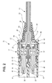
Fig. 2 is a sectional view taken along a direction of an optical fiber of the optical connector according to the embodiment of the invention. -
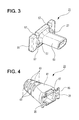
Fig. 3 is an overall perspective view showing a crimping sleeve shown inFig. 1 . -
Fig. 4 is an overall perspective view showing a boot shown inFig. 4 . -
Fig. 5A is a sectional view showing a main part before a tension force is exerted on the optical fiber of the optical cable shown inFig. 2 , andFig. 5B is a sectional view showing the main part after the tension force is exerted on the optical fiber of the optical cable shown inFig. 2 -
Fig. 6 is an overall view showing a variant of a protrusion engaging hole of the boot shown inFig. 4 . -
Fig. 7 is a partially broken enlarged plan view showing a conventional optical connector. - An optical connector according to one embodiment of the present invention will be now described in detail with reference to the accompanying drawings.
- The
optical connector 11 according to the present embodiment is coupled to a corresponding optical connector, not shown, so that distal ends ofoptical fibers 15, which are core wires ofoptical fiber cables 13, are abutted and connected to each other. Accordingly, optical fibers, for example, for a vehicle LAN or the like are connected to each other. - As shown in
Figs. 1 and2 , theoptical connector 11 according to the present embodiment includes ahousing 17 for receiving aferrule 19 connected to a distal end of the optical fiber of theoptical fiber cable 13; acrimping sleeve 21 including atubular portion 53 adapted to allow theoptical fiber 15 to be inserted therethrough and also adapted to be inserted through a sleeve through-hole 51 formed in arear wall 49 of thehousing 17, and asandwiching flange portion 55 continued from thetubular portion 53 and facing an rear wallinner surface 59 of thehousing 17; acrimping ring 29 for fixing asheath 35 of theoptical fiber cable 13 sheathed on an outer circumference of thetubular portion 53; and aboot 23 including a protective portion for covering outer circumferences of theoptical fiber cable 13 and the crimpingring 29, and alocking flange portion 65 continued from the protective portion and sandwiched between thesandwiching flange portion 55 and the rear wallinner surface 59. - Among these, the
optical fiber cable 13, theferrule 19, thecrimping sleeve 21, thecrimping ring 29 and theboot 23 constitute aferrule assembly 31. - The
housing 17 made of a synthetic resin has, on a front side thereof, couplingopening portions 33 intended to be coupled with the corresponding optical connector, not shown. A pair offerrules 19 are received inside thecoupling opening portions 33. - The
optical fiber 15 exposed by removing thesheath 35 and a tension-resistance body, not shown, from theoptical fiber cable 13 is inserted and fixed in each of theferrules 19. Theseferrules 19 are movably received in thehousing 17 in an axial direction thereof, and are elastically urged forward by aleaf spring 37 received in thehousing 17. Theleaf spring 37 is prevented from being separated from thehousing 17 by astopper 39. - As shown in
Fig. 2 , theferrules 19 elastically urged forward by theleaf spring 37 are adapted such thatannular portions 45 thereof are abutted to stopperwalls 43 formed to protrude insideferrule receiving holes 41, and thus are prevented from protruding further forward. Theferrules 19 are abutted and connected to ferrules of the corresponding optical connector byjoint end surfaces 47 thereof. Thus, theoptical fibers 15 terminated to allow connector-connection by theferrules 19 are connected to optical lines of the corresponding optical connector. - Upon abutting against the corresponding optical connector, the
ferrules 19 can be slightly pushed backward in a connection direction within a range of elastic deformation of theleaf spring 37, and therefore, damage due to an extreme stress concentration or the like is prevented. In addition, the urging force of theleaf spring 37 is acted as an abutting force between ferrules, and a desired connection loss can be stably achieved. - The sleeve through-
hole 51 is formed in therear wall 49 of thehousing 17. Theoptical fibers 15 connected to theferrules 19 are led out through the sleeve through-hole 51. The crimpingsleeve 21 is interposed between theoptical fibers 15 and the sleeve through-hole 51. - As shown in
Fig. 3 , thecrimping sleeve 21 is made of a hard resin material, and has the flattubular portion 53 through which theoptical fibers 15 are inserted. On a front side of thetubular portion 53, thesandwiching flange portion 55 of a rectangular shape is provided to be connected in line thereto (to be continued therefrom). - On upper and lower edges of the sandwiching
flange portion 55, a plurality ofrecesses 57 intended to be engaged with ribs, not shown, inside thehousing 17 are formed. The crimpingsleeve 21 is assembled in thehousing 17 so that thetubular portion 53 is inserted through the through-hole 51 of therear wall 49 and the sandwichingflange portion 55 faces the rear wallinner surface 59. Theoptical fibers 15 are inserted through thetubular portion 53 of the crimpingsleeve 21 assembled in that way. - The
optical fiber cable 13 is adapted such that theoptical fibers 15 are led out from thetubular portion 53 of the crimpingsleeve 21, while thesheath 35 thereof is sheathed on the outer circumference of thetubular portion 53. Thesheath 35 sheathed on thetubular portion 53 is fixed on thetubular portion 53 by crimping the crimpingring 29 from the outside thereof. Thus, theoptical fiber cable 13 and the crimpingsleeve 21 are integrally fixed to each other. When theoptical fiber cable 13 is pulled backward, the sandwichingflange portion 55 is abutted to therear wall 49, thereby restricting separation of the crimpingsleeve 21. - As shown in
Fig. 4 , theboot 23 is made of a soft material, such as a synthetic rubber, and has theprotective portion 61 for covering outer circumferences of theoptical fiber cable 13 and the crimpingring 29. A plurality ofperipheral grooves 63 for imparting a suitable flexibility to theprotective portion 61 are formed around theprotective portion 61. Theboot 23 has the lockingflange portion 65 of a rectangular shape extending through the sleeve through-hole 51 of thehousing 17 and continued from theprotective portion 61. Theboot 23 is assembled in thehousing 17 by sandwiching the lockingflange portion 65 between the sandwichingflange portion 55 of the crimpingsleeve 21 and the rear wallinner surface 59 of thehousing 17 as shown inFig. 2 . - A
ring receiving hole 67 for receiving the crimpingring 29 is concentrically formed in theboot 23. Thering receiving hole 67 is opened at the center of the lockingflange portion 65. On an inner side of the lockingflange portion 65, a pair of protrusion locking holes 25 are formed with thering receiving hole 67 interposed therebetween. Therefore, the pair of protrusion locking holes 25 are respectively arranged on left and right sides with thetubular portion 53 of the crimpingsleeve 21 interposed therebetween. According to the present embodiment, the protrusion locking holes 25 are formed in a C shape, and are opened toward thering receiving hole 67 by sharing the periphery thereof with thering receiving hole 67. - Meanwhile, on the sandwiching
flange portion 55 of the crimpingsleeve 21, as shown inFig. 3 , a pair ofboot locking protrusions 27 is formed to protrude between the sandwichingflange portion 55 interposed therebetween. The pair ofboot locking protrusions 27 having a cylindrical shape are respectively fitted in the protrusion locking holes 25 of the lockingflange portion 65 sandwiched between the sandwichingflange portion 55 and the rear wallinner surface 59. - According to the
optical connector 11 of the present embodiment, the protrusion locking holes 25 and theboot locking protrusions 27 are provided in a pair with thetubular portion 53 interposed therebetween, and therefore, the lockingflange portion 65 is locked to theboot locking protrusions 27 on both side in a diameter direction thereof with the center of theoptical fiber cable 13 interposed therebetween, and thus is stably locked without being deformed by a strain. - Also, the
optical connector 11 is configured such that a protrusion length of theboot locking protrusions 27 is set to be smaller than a thickness of the lockingflange portion 65. Thus, when theoptical fiber cable 13 is pulled, the sandwichingflange portion 55 of the crimpingsleeve 21 can press the lockingflange portion 65 before theboot locking protrusions 27 are abutted to the rear wallinner surface 59, and as result, pulling out of the lockingflange portion 65 can be prevented by both sandwiching and locking actions. - Next, operations of the
optical connector 11 having the above configurations will be described. - Upon assembling the
optical connector 11, theoptical fiber cable 13 is inserted through theboot 23, the crimpingring 29 and the crimpingsleeve 21 in this order. Then, in the inside of thetubular portion 55 of the crimpingsleeve 21, theoptical fibers 15 exposed by removing thesheath 35 are inserted therethrough, whereas on the outer circumference of thetubular portion 55, thesheath 35 of theoptical fiber cable 13 is fixed by the crimpingring 29. - The crimping
sleeve 21 fixed on theoptical fiber cable 13 is restricted from being separated by making the sandwichingflange portion 55 face the rear wallinner surface 59 inside thehousing 17. Theboot 23, of which theprotective portion 61 is covering a portion of theoptical fiber cable 13 and the crimpingring 23, is adapted such that the lockingflange portion 65 continued from theprotective portion 61 and extending through the sleeve through-hole 51 is sandwiched between the sandwichingflange portion 55 of the crimpingsleeve 21 and the rear wallinner surface 59 of the hosing 17. - In addition, the
boot locking protrusions 27 formed to protrude on the sandwichingflange portion 55 are inserted in the protrusion locking holes 25 formed in the lockingflange portion 65. - The
optical connector 11 assembled in this way is adapted such that, as shown inFig. 5A , the lockingflange portion 65 sandwiched between the sandwichingflange portion 55 and the rear wallinner surface 59 is pulled toward the sleeve through-hole 51 when theboot 23 is pulled as a unity body. When the lockingflange portion 65 is pulled toward the sleeve through-hole 51, the protrusion locking holes 25 radially moving inward are locked to theboot locking protrusions 27, thereby preventing the lockingflange portion 65 form being pulled out from the sleeve through-hole 51. - Also, as shown in
Fig. 5B , if the optical fiber cable 1 is pulled backward (the right side in the figure) due to bending of the optical fiber cable or the like, the sandwichingflange portion 55 of the crimpingsleeve 21 fixed by the crimpingring 29 is pressed against the rear wall inner surfaceinner surface 59 as shown inFig. 5B . The sandwichingflange portion 55 pressed against the rear wallinner surface 59 further surely prevents the lockingflange portion 65 from being pulled out, because the sandwichingflange portion 55 and the rear wallinner surface 59 sandwich the lockingflange portion 65 of theboot 23 therebetween and also theboot locking protrusions 27 come into pressure contact with the rear wallinner surface 59. - Therefore, according to the
optical connector 11 of the present embodiment as described above, separation of the boot due to inadvertent pulling of the boot or loosening of the optical fiber cable bending can be prevented without increasing operation man-hours or material costs. - Meanwhile, it will be appreciated that components, such as the optical cable, the optical fiber, the ferrules, the housing, the crimping sleeve, the crimping ring, the boot, the boot locking protrusions and the protrusion locking holes, according to the optical connector of the present invention are not limited to the configurations of the foregoing embodiment, but can employ various configurations on the basis of the spirit of the present invention.
- Although the
boot 23 according to the foregoing embodiment has been illustrated as a configuration example in which the protrusion locking holes 25 formed in the inner side of the lockingflange portion 65 are opened in a C shape, the optical connector according to the present invention is not limited to such a configuration. For example, as in aboot 73 shown inFig. 6 , the protrusion locking holes may be constituted as protrusion locking holes 69, whose peripheries are closed, and an opening shape thereof is not also limited to a circular shape, but may employ various shapes, such as a elliptic shape or a polygonal shape. - In addition, the boot locking protrusions of the sandwiching flange portion intended to be inserted into the protrusion locking holes of the locking flange portion are not also limited to a circular cylindrical shape, but may employ various shape, such as an elliptic cylindrical shape or a polygonal prism shape.
- Meanwhile, the present invention is not limited to the foregoing embodiment, but appropriate changes, modifications or the like thereof can be made. In addition, material, shape, dimension, number, installation position and the like of each of the components of the foregoing embodiment are not limited but arbitrary as long as the present invention can be achieved.
- Also, this application is based on Japanese Patent Application Serial No.
2011-086529 filed on April 8, 2011 - According to the optical connector of the present invention, separation of the boot due to inadvertent pulling of the boot or loosening of the optical fiber cable bending can be prevented without increasing operation man-hours or material costs.
-
- 11
- Optical connector
- 13
- Optical fiber cable
- 15
- Optical fiber
- 17
- Housing
- 19
- Ferrule
- 21
- Crimping sleeve
- 23
- Boot
- 25
- Protrusion locking hole
- 27
- Boot locking protrusion
- 29
- Crimping ring
- 35
- Sheath
- 49
- Rear wall
- 51
- Sleeve through-hole
- 53
- Tubular portion
- 55
- Sandwiching flange portion
- 59
- Rear wall inner surface
- 61
- Protective portion
- 65
- Engaging flange portion
Claims (3)
- An optical connector, comprising:a housing for receiving a ferrule connected to a distal end of an optical fiber of an optical fiber cable;a crimping sleeve including a tubular portion adapted to allow the optical fiber to be inserted therethrough and also adapted to be inserted through a sleeve through-hole formed in a rear wall of the housing, and a sandwiching flange portion continued from the tubular portion and facing an rear wall inner surface of the housing;a crimping ring for fixing a sheath of the optical fiber cable sheathed on an outer circumference of the tubular portion; anda boot including a protective portion for covering outer circumferences of the optical fiber cable and the crimping ring, and a locking flange portion continued from the protective portion and sandwiched between the sandwiching flange portion and the rear wall inner surface,wherein a boot locking protrusion formed on the sandwiching flange portion is inserted in a protrusion locking hole formed in an inner side of the locking flange portion.
- The optical connector according to claim 1, wherein a pair of protrusion locking holes and a pair of boot locking protrusions are provided with the tubular portion interposed therebetween.
- The optical connector according to claim 1 or 2, wherein a protrusion length of the boot locking protrusion is smaller than a thickness of the locking flange portion.
Applications Claiming Priority (2)
| Application Number | Priority Date | Filing Date | Title |
|---|---|---|---|
| JP2011086529A JP2012220731A (en) | 2011-04-08 | 2011-04-08 | Optical connector |
| PCT/JP2012/059595 WO2012137954A1 (en) | 2011-04-08 | 2012-04-06 | Optical connector |
Publications (2)
| Publication Number | Publication Date |
|---|---|
| EP2696228A1 true EP2696228A1 (en) | 2014-02-12 |
| EP2696228A4 EP2696228A4 (en) | 2014-10-08 |
Family
ID=46969342
Family Applications (1)
| Application Number | Title | Priority Date | Filing Date |
|---|---|---|---|
| EP12767593.2A Withdrawn EP2696228A4 (en) | 2011-04-08 | 2012-04-06 | OPTICAL CONNECTOR |
Country Status (6)
| Country | Link |
|---|---|
| US (1) | US20140037252A1 (en) |
| EP (1) | EP2696228A4 (en) |
| JP (1) | JP2012220731A (en) |
| KR (1) | KR101462365B1 (en) |
| CN (1) | CN103460096A (en) |
| WO (1) | WO2012137954A1 (en) |
Families Citing this family (8)
| Publication number | Priority date | Publication date | Assignee | Title |
|---|---|---|---|---|
| JP6122291B2 (en) * | 2012-08-10 | 2017-04-26 | 矢崎総業株式会社 | Optical connector and optical connector assembling method |
| JP6272649B2 (en) * | 2013-02-15 | 2018-01-31 | 矢崎総業株式会社 | Optical connector |
| JP5736490B1 (en) * | 2014-05-29 | 2015-06-17 | 株式会社フジクラ | Optical fiber unit with connector, optical connector boot |
| CN105100082A (en) * | 2015-07-02 | 2015-11-25 | 惠州Tcl移动通信有限公司 | Method and system for accessing cloud terminal to home cloud system, and cloud access control equipment |
| CN106918869B (en) * | 2017-04-17 | 2018-10-26 | 深圳市飞博康光通讯技术有限公司 | A kind of LC duplexs connector |
| JP6796622B2 (en) * | 2018-07-19 | 2020-12-09 | 株式会社フジクラ | Optical connector |
| EP4073564B1 (en) * | 2019-12-10 | 2026-05-06 | PPC Broadband, Inc. | Mechanical connector with cable retention feature |
| JP2022050763A (en) * | 2020-09-18 | 2022-03-31 | 矢崎総業株式会社 | Optical connector |
Family Cites Families (14)
| Publication number | Priority date | Publication date | Assignee | Title |
|---|---|---|---|---|
| JPH077139B2 (en) * | 1985-12-24 | 1995-01-30 | 日本電信電話株式会社 | Floating holder type optical connector |
| US4787706A (en) * | 1987-02-03 | 1988-11-29 | American Telephone And Telegraph Company, At&T Bell Laboratories | Duplex optical fiber connector |
| JPH0497108A (en) * | 1990-08-09 | 1992-03-30 | Furukawa Electric Co Ltd:The | Optical connector |
| JP2576911Y2 (en) * | 1991-08-27 | 1998-07-23 | 日本エー・エム・ピー株式会社 | Optical connector |
| US5418874A (en) * | 1994-01-19 | 1995-05-23 | At&T Corp. | Force transfer system for an optical fiber connector |
| JP3282974B2 (en) * | 1996-10-02 | 2002-05-20 | 住友電装株式会社 | Optical connector |
| EP1145061B1 (en) * | 1998-12-22 | 2003-04-16 | Rako Electronic Data Technology GmbH | Connector for optical waveguides comprising a connector housing |
| US6422764B1 (en) * | 2000-03-01 | 2002-07-23 | Panduit Corp. | Clamping mechanism for an optical fiber |
| JP5281959B2 (en) | 2008-06-12 | 2013-09-04 | 株式会社精工技研 | An optical connector stop ring, an optical fiber cord with an optical connector using the stop ring, and a method of manufacturing an optical fiber cord with an optical connector. |
| US7993063B2 (en) * | 2009-03-16 | 2011-08-09 | Panduit Corp. | Block-out device for fiber optic adapter |
| JP5599237B2 (en) * | 2010-06-23 | 2014-10-01 | 矢崎総業株式会社 | Optical connector |
| JP5771075B2 (en) * | 2010-12-28 | 2015-08-26 | 矢崎総業株式会社 | Optical connector |
| JP5882765B2 (en) * | 2012-02-02 | 2016-03-09 | 矢崎総業株式会社 | Optical connector |
| JP6122291B2 (en) * | 2012-08-10 | 2017-04-26 | 矢崎総業株式会社 | Optical connector and optical connector assembling method |
-
2011
- 2011-04-08 JP JP2011086529A patent/JP2012220731A/en not_active Withdrawn
-
2012
- 2012-04-06 EP EP12767593.2A patent/EP2696228A4/en not_active Withdrawn
- 2012-04-06 WO PCT/JP2012/059595 patent/WO2012137954A1/en not_active Ceased
- 2012-04-06 KR KR1020137026639A patent/KR101462365B1/en active Active
- 2012-04-06 CN CN2012800174214A patent/CN103460096A/en active Pending
-
2013
- 2013-10-08 US US14/048,260 patent/US20140037252A1/en not_active Abandoned
Non-Patent Citations (2)
| Title |
|---|
| No further relevant documents disclosed * |
| See also references of WO2012137954A1 * |
Also Published As
| Publication number | Publication date |
|---|---|
| CN103460096A (en) | 2013-12-18 |
| KR101462365B1 (en) | 2014-11-14 |
| JP2012220731A (en) | 2012-11-12 |
| EP2696228A4 (en) | 2014-10-08 |
| WO2012137954A1 (en) | 2012-10-11 |
| KR20130136527A (en) | 2013-12-12 |
| US20140037252A1 (en) | 2014-02-06 |
Similar Documents
| Publication | Publication Date | Title |
|---|---|---|
| US20140037252A1 (en) | Optical connector | |
| KR101422991B1 (en) | Optical connector | |
| EP2810110B1 (en) | Optical connector | |
| JP6122291B2 (en) | Optical connector and optical connector assembling method | |
| US8539796B2 (en) | Method for assembling optical connector | |
| US20150241642A1 (en) | Optical connector | |
| US8500340B2 (en) | Optical ferrule assembly | |
| JP6272649B2 (en) | Optical connector | |
| JP5695774B1 (en) | Method for retaining optical connector and protective tube | |
| JP5873760B2 (en) | Optical connector | |
| US10877221B2 (en) | Fiber optic connector | |
| WO2014119585A1 (en) | Optical connector and method for assembling optical connector | |
| WO2023190651A1 (en) | Optical fiber cable with optical connector, method for manufacturing optical fiber cable with optical connector, and optical connector | |
| JP2014044328A (en) | Optical connector | |
| US20120051698A1 (en) | Optical Fiber Terminus | |
| JP2014044329A (en) | Cable holding structure for optical connector | |
| CN218601515U (en) | MPO connector | |
| KR20180131725A (en) | United optic connector | |
| JP2005107027A (en) | Optical fiber with optical connector |
Legal Events
| Date | Code | Title | Description |
|---|---|---|---|
| PUAI | Public reference made under article 153(3) epc to a published international application that has entered the european phase |
Free format text: ORIGINAL CODE: 0009012 |
|
| 17P | Request for examination filed |
Effective date: 20131008 |
|
| AK | Designated contracting states |
Kind code of ref document: A1 Designated state(s): AL AT BE BG CH CY CZ DE DK EE ES FI FR GB GR HR HU IE IS IT LI LT LU LV MC MK MT NL NO PL PT RO RS SE SI SK SM TR |
|
| DAX | Request for extension of the european patent (deleted) | ||
| A4 | Supplementary search report drawn up and despatched |
Effective date: 20140904 |
|
| RIC1 | Information provided on ipc code assigned before grant |
Ipc: G02B 6/40 20060101ALI20140829BHEP Ipc: G02B 6/38 20060101AFI20140829BHEP |
|
| STAA | Information on the status of an ep patent application or granted ep patent |
Free format text: STATUS: THE APPLICATION HAS BEEN WITHDRAWN |
|
| 18W | Application withdrawn |
Effective date: 20150518 |