EP2696221A1 - Optical member and method for manufacturing optical member - Google Patents
Optical member and method for manufacturing optical member Download PDFInfo
- Publication number
- EP2696221A1 EP2696221A1 EP13003694.0A EP13003694A EP2696221A1 EP 2696221 A1 EP2696221 A1 EP 2696221A1 EP 13003694 A EP13003694 A EP 13003694A EP 2696221 A1 EP2696221 A1 EP 2696221A1
- Authority
- EP
- European Patent Office
- Prior art keywords
- aluminium
- layer
- base material
- compound
- boron
- Prior art date
- Legal status (The legal status is an assumption and is not a legal conclusion. Google has not performed a legal analysis and makes no representation as to the accuracy of the status listed.)
- Granted
Links
Images




Classifications
-
- G—PHYSICS
- G02—OPTICS
- G02B—OPTICAL ELEMENTS, SYSTEMS OR APPARATUS
- G02B1/00—Optical elements characterised by the material of which they are made; Optical coatings for optical elements
- G02B1/10—Optical coatings produced by application to, or surface treatment of, optical elements
- G02B1/11—Anti-reflection coatings
- G02B1/113—Anti-reflection coatings using inorganic layer materials only
- G02B1/115—Multilayers
-
- G—PHYSICS
- G02—OPTICS
- G02B—OPTICAL ELEMENTS, SYSTEMS OR APPARATUS
- G02B1/00—Optical elements characterised by the material of which they are made; Optical coatings for optical elements
- G02B1/10—Optical coatings produced by application to, or surface treatment of, optical elements
- G02B1/11—Anti-reflection coatings
- G02B1/111—Anti-reflection coatings using layers comprising organic materials
-
- G—PHYSICS
- G02—OPTICS
- G02B—OPTICAL ELEMENTS, SYSTEMS OR APPARATUS
- G02B1/00—Optical elements characterised by the material of which they are made; Optical coatings for optical elements
- G02B1/10—Optical coatings produced by application to, or surface treatment of, optical elements
- G02B1/11—Anti-reflection coatings
- G02B1/118—Anti-reflection coatings having sub-optical wavelength surface structures designed to provide an enhanced transmittance, e.g. moth-eye structures
-
- Y—GENERAL TAGGING OF NEW TECHNOLOGICAL DEVELOPMENTS; GENERAL TAGGING OF CROSS-SECTIONAL TECHNOLOGIES SPANNING OVER SEVERAL SECTIONS OF THE IPC; TECHNICAL SUBJECTS COVERED BY FORMER USPC CROSS-REFERENCE ART COLLECTIONS [XRACs] AND DIGESTS
- Y10—TECHNICAL SUBJECTS COVERED BY FORMER USPC
- Y10T—TECHNICAL SUBJECTS COVERED BY FORMER US CLASSIFICATION
- Y10T428/00—Stock material or miscellaneous articles
- Y10T428/24—Structurally defined web or sheet [e.g., overall dimension, etc.]
- Y10T428/24355—Continuous and nonuniform or irregular surface on layer or component [e.g., roofing, etc.]
Definitions
- the present invention relates to an optical member having a high antireflective performance in a broad region including a visible region for a base material with a low refractive index, and a method for manufacturing the optical member.
- An antireflective structure having a fine structure corresponding to those equal to or smaller than wavelengths in a visible region is known to exhibit an antireflective performance in a broad wavelength region by forming a fine structure with an appropriate pitch and an appropriate height.
- a method of forming the fine structure a film in which fine particles having a particle diameter equal to or smaller than a wavelength are dispersed is known.
- a method of forming the fine structure by a pattern formation by a fine processing apparatus (such as an electron ray drawing apparatus, a laser interference exposure apparatus, a semiconductor exposure apparatus, an etching apparatus) enables control of a pitch and a height, and the method is also known to be able to form the fine structure having the good antireflective performance.
- boehmite which is an alumina-based compound
- a film is formed by a vacuum film formation or a liquid phase method (sol gel method), and then the film is dried or burned to produce a film of aluminium oxide.
- boehmite is produced on its surface layer to form a fine structure, followed by making an antireflective film (see Japanese Patent Application Laid-Open No. 9-202649 ).
- the antireflective film is formed by forming a layer supporting the fine structure between the substrate and the fine structure so that the substrate does not influence the fine structure.
- a reflectance due to a vertical incidence and an oblique incidence is low, and the good antireflective performance can be obtained.
- the antireflective performance of the antireflective film using the fine structure of the aluminium compound disclosed in Japanese Patent Application Laid-Open No. 9-202649 sensitively changes due to changes of the refractive index attributed to the pitch and the height of the fine structure. Therefore, it is required to control not only the pitch and the height of the fine structure but also the refractive index of the layer supporting the fine structure according to the refractive index of the base material, and in some cases, it is also required to provide a film made of an inorganic material or an organic material for the purpose of regulating a refractive index difference between the base material and the aluminium oxide film having the fine structure.
- the metal compound to be mixed is limited to compounds of zirconia, silica, titania and zinc oxide, and thus, it is restricted that the refractive index of the layer supporting the fine structure is reduced and the pitch and the height of the fine structure are suitably controlled. In particular, it has been required to obtain the good antireflective performance for the base material having the low refractive index.
- the present invention is directed to an optical member including protrusions made mainly of aluminium oxide and a porous aluminium oxide layer as a layer supporting the protrusions, and a method for manufacturing the optical member.
- Fig. 1 is a cross-sectional photograph (magnification: 20,000 times) of an optical member captured by a scanning electron microscope (SEM) according to an exemplary embodiment of the present invention.
- SEM scanning electron microscope
- Fig. 2 is a cross-sectional photograph (magnification: 20,000 times), captured by the SEM, of an amorphous aluminium oxide film produced from a coating solution according to the exemplary embodiment of the present invention.
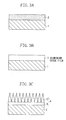
- Figs. 3A, 3B and 3C are views illustrating a method for manufacturing of the optical member according to the exemplary embodiment of the present invention.
- Fig. 4 is a schematic view illustrating the optical member according to the exemplary embodiment of the present invention.
- Fig. 5 is a schematic view illustrating the optical member according to the exemplary embodiment of the present invention.
- Fig. 6 is a schematic view illustrating the optical member according to the exemplary embodiment of the present invention.
- Fig. 7 is a schematic view illustrating the optical member according to the exemplary embodiment of the present invention.
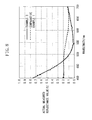
- Fig. 8 is a view illustrating reflectances in an example and a comparative example.
- An optical member according to the present exemplary embodiment includes a base material and an antireflective layer including a plurality of fine protrusions on its surface.
- the antireflective layer also contains boron.
- the optical member in the present exemplary embodiment can exert a high antireflective performance in a broad region including a visible region for the base material with a low refractive index.
- Glasses and plastics can be used as the base material to be used in the present exemplary embodiment.
- Representative plastics that compose the base material include thermoplastic resins such as polyester, triacetylcellulose, cellulose acetate, polyethylene terephthalate, polypropylene, polystyrene, polycarbonate, polymethyl methacrylate, ABS resins, polyphenylene oxide, polyurethane, polyethylene, and polyvinyl chloride; and thermosetting resins such as unsaturated polyester resins, phenol resins, crosslinked polyurethane, crosslinked acryl resins, and crosslinked saturated polyester resins.
- a molded article such as a lens, or a film can also be used as the base material. It is desirable to use the glass as the base material in terms of transparency and moldability.
- the antireflective layer according to the present exemplary embodiment can exert the excellent antireflective performance also for the base material with a low refractive index.
- the base material having the refractive index n d of 1.48 or more and 1.71 or less can be used.
- the antireflective layer according to the present exemplary embodiment has a plurality of fine protrusions on its surface and contains boron.
- An apparent refractive index in the antireflective layer is desirably changed in a thickness direction. That is, it is desirable that the refractive index be changed from the surface of the antireflective layer toward the base material.
- the antireflective layer also desirably has the apparent refractive index that is lower than the refractive index inherent to aluminium oxide. The antireflective layer including such a configuration can exert the better antireflective performance.
- An average surface roughness Ra' in the antireflective layer is desirably 15 nm or more and 100 nm or less, and more desirably 18 nm or more and 25 nm or less. When the average surface roughness Ra' is less than 15 nm, the antireflective performance is reduced. When the average surface roughness Ra' is more than 100 nm, scattering in the antireflective layer tends to increase.
- a surface area ratio Sr of the antireflective layer is desirably 1.2 or more and 3.5 or less.
- the surface area S is obtained by summation of ⁇ S, and the surface area ratio Sr of the antireflective layer is also obtained.
- the protrusion on the surface of the antireflective layer be made mainly of aluminium oxide.
- the protrusion is formed from a crystal of an oxide or a hydroxide of aluminium or a hydrate thereof.
- the protrusion is more desirably boehmite.
- the oxide or the hydroxide of aluminium or the hydrate thereof is described herein as "aluminium oxide”.
- a layer thickness of an antireflective layer 7 including protrusions 8 is desirably 20 nm or more and 1000 nm or less and more desirably 50 nm or more and 1000 nm or less.
- the thickness of the antireflective layer 7 including the protrusions 8 is less than 20 nm, a mechanical strength is reduced, and when the thickness is more than 1000 nm, the antireflective performance is reduced.
- a thickness of the protrusion 8 is desirably 5 nm or more and 50 nm or less.
- the "thickness of the protrusion" is defined as a value of a width at a height that is a half of a height of the protrusion. The thickness of the protrusion is obtained from a mean value of the thicknesses of 100 protrusions on an SEM photograph of the optical member.
- a treatment can be given to the surface of the protrusion 8 to an extent that the antireflective performance is not impaired.
- the surface of the protrusion 8 can be provided with a thin film formed of SiO 2 , a very thin film formed of fluorinated alkyl silane (FAS), or a very thin layer formed of a fluorine resin in order to impart an abrasion resistance and an antifouling property.
- FAS fluorinated alkyl silane
- the optical member in the present exemplary embodiment desirably includes a support layer that supports the protrusions, between the base material and the protrusions.
- a thickness of the support layer is desirably 10 nm or more and 100 nm or less.
- the support layer is desirably porous.
- the support layer is desirably made mainly of aluminium oxide and contains boron, and is more desirably formed from aluminium oxide and boron.
- Fig. 2 is an SEM cross-sectional photograph of an amorphous aluminium oxide layer formed on the base material surface before being immersed into hot water to form the protrusion, in the method for manufacturing the optical member in the present exemplary embodiment.
- amorphous aluminium oxide layer is immersed into the hot water to form the protrusion.
- no porous layer like the support layer that supports the protrusions in the optical member in the present exemplary embodiment is observed. That is, it is thought that a boron compound is eluted into the hot water, thereby forming the porous layer simultaneously when the amorphous aluminium oxide layer is immersed into the hot water to form the protrusions.
- a porosity in the cross-section of the layer that supports the protrusions is desirably 20% or more and 45% or less in the present exemplary embodiment. When the porosity exceeds 45%, the strength of the layer that supports the protrusions becomes weak and the film is sometimes peeled.
- the refractive index in the amorphous aluminium oxide layer tends to decrease as the content of boron is increased.
- the refractive index in the layer decreases by containing boron in the support layer even if the support layer is not porous. Therefore, it is conceivable that containing boron in the support layer supporting the protrusions has an effect of further decreasing the refractive index.
- the support layer desirably contains boron in an amount of 7.0 ⁇ 10 19 atoms/cm 3 or more and 2.5 ⁇ 10 20 atoms/cm 3 or less. It is possible to change the refractive index in the layer supporting the protrusions by changing the porosity in the porous layer. This can change the content of boron in the support layer.
- Fig. 1 is an SEM cross-sectional photograph of the optical member in the present exemplary embodiment.
- a portion (a) of protrusions and a portion (b) of a support layer that supports the protrusions are present. It is further found from Fig. 1 that the support layer (b) that supports the protrusions is porous.
- the optical member according to the present exemplary embodiment is applicable to a transparent base material having any refractive index, and exhibits an excellent antireflective effect for visible light and has a weather resistance for a long period of time. Therefore, the optical member in the present exemplary can be utilized as optical members in various displays in word processors, computers, televisions, and plasma display panels, and can also be utilized as optical members in sunglass lenses, prescription glass lenses, finder lenses for cameras, prisms, fly-eye-lenses, toric lenses, various optical filters, and sensors formed from polarizing plates used for liquid crystal display devices, various optical glass materials, and transparent plastics.
- optical member in the present exemplary can also be utilized as optical members in various systems, using the above, like a photographing optical system, an observing optical system such as binoculars, and a projecting optical system such as liquid crystal projectors; various optical lenses in a scanning optical system such as laser beam printers; and covers of various instruments and window glasses of automobiles and electric trains.
- the optical member in the present exemplary embodiment can change a refractive index structure in the antireflective layer 7 including the protrusions 8 of aluminium oxide and the support layer 9 according to the refractive index in the base material by using the porous aluminium oxide film in the support layer 9.
- a layer made mainly of a component other than aluminium oxide can be provided between the base material 1 and the antireflective layer 7 including the protrusions 8 and the support layer 9.
- Fig. 7 illustrates an example of an optical member in which a layer 12 made mainly of a component other than aluminium oxide is formed on the base material 1 and further an antireflective layer 4 including protrusions 5 of aluminium oxide and a support layer 6 is formed thereon.
- the layer 12 made mainly of the component other than aluminium oxide is provided mainly for the purpose of regulating a refractive index difference between the base material 1 and the antireflective layer 4 including the protrusions 5 of aluminium oxide and the support layer 6.
- the layer 12 made mainly of the component other than aluminium oxide is desirably a transparent layer formed from an inorganic compound or an organic compound.
- Examples of the inorganic compound used for the layer 12 made mainly of the component other than aluminium oxide include metal oxides such as SiO 2 , TiO 2 , ZrO 2 , ZnO, and Ta 2 O 3 .
- the layer 12 made mainly of the inorganic material other than aluminium oxide can be formed by a vacuum film forming method such as deposition or sputtering, or a sol gel method by applying a metal oxide precursor sol.
- Examples of the organic compound used for the layer 12 made mainly of the component other than aluminium oxide include organic polymers such as acryl resins, epoxy resins, oxetane resins, maleimide resins, melamine resins, benzoguanamine resins, phenol resins, resol resins, polycarbonate, polyester, polyacrylate, polyether, polyurea, polyurethane, polyamide, polyamideimide, polyimide, polyketone, polysulfone, polyphenylene, polyxylylene and polycycloolefin.
- the layer 12 formed from the organic material can be formed by a wet coating method by mainly applying its solution.
- the method for manufacturing the optical member in the present exemplary embodiment relates to a method for manufacturing an optical member including a base material and an antireflective layer.
- the method for manufacturing the optical member according to the present exemplary embodiment includes a step of forming a layer made mainly of aluminium oxide and containing boron on the surface of the base material and a step of treating the formed layer made mainly of aluminium oxide in hot water at temperature of 60°C to 100°C or an aqueous medium at temperature of 60°C to 100°C to form the reflective layer including a plurality of fine protrusions on its surface.
- the layer containing boron and made mainly of aluminium oxide is formed on the surface of the base material.
- a first solution is prepared by mixing a solvent and an aluminium compound.
- a second solution is prepared by mixing the resulting first solution with an aqueous medium to hydrolyze the aluminium compound.
- the resulting second solution is mixed with a boron compound to prepare a coating solution for forming the antireflective layer.
- the resulting coating solution is applied onto the surface of the base material to form a layer (coating film) on the surface of the base material.
- the solvent used in the first solution can be an organic solvent in which a raw material such as the aluminium compound is uniformly dissolved and its particles do not agglutinate.
- a raw material such as the aluminium compound is uniformly dissolved and its particles do not agglutinate.
- Examples thereof include monovalent alcohols such as methanol, ethanol, 1-propanol, 2-propanol, 1-butanol, 2-butanol, 2-methylpropanol, 1-pentanol, 2-pentanol, cyclopentanol, 2-methylbutanol, 3-methylbutanol, 1-hexanol, 2-hexanol, 3-hexanol, 4-methyl-2-pentanol, 2-methyl-1-pentanol, 2-ethylbutanol, 2,4-dimethyl-3-pentanol, 3-ethylbutanol, 1-heptanol, 2-heptanol, 1-octanol, and 2-
- monovalent alcohols having 5 or more and 8 or less carbon atoms are desirable in terms of high solubility of the aluminium compound and difficult moisture absorption.
- the monovalent alcohol having 5 or more and 8 or less carbon atoms is highly hydrophobic and cannot be mixed uniformly with water required for hydrolysis, and it is difficult to make particle diameters constant.
- a water-soluble solvent refers to a solvent in which water is soluble at 80% by mass or more at temperature of 23°C.
- the aluminium compound used in the first solution is desirably an aluminium alkoxide or aluminium salt compound. More specifically, the aluminium compound is desirably a compound selected from the group consisting of aluminium ethoxide, aluminium isopropoxide, aluminium-n-butoxide, aluminium-sec-butoxide, aluminium-tert-butoxide, aluminium acetyl acetonate or oligomers thereof, aluminium nitrate, aluminium chloride, aluminium acetate, aluminium phosphate, aluminium sulfate, and aluminium hydroxide.
- aluminium-n-butoxide and aluminium-sec-butoxide it is more desirable to use metal alkoxide such as aluminium-n-butoxide and aluminium-sec-butoxide as a raw material.
- Aluminium alkoxide is highly reactive with water and rapidly hydrolyzed by water in air or the addition of water to produce a cloudy solution or a precipitation.
- the aluminium salt compound is difficult to be dissolved in the organic solvent alone, and its solution is poorly stable. To prevent this, it is desirable to add a stabilizer to stabilize the solution.
- the stabilizer used in the first solution is desirably a ⁇ -diketone compound or a ⁇ -ketoester compound.
- the ⁇ -diketone compound having a hydrogen atom, a halogen atom, an alkyl group having 1 or more and 6 or less carbon atoms, a perfluoroalkyl group, an allyl group, or an aryl group at position ⁇ is more desirable. It is more desirable to use the ⁇ -diketone compound having an alkyl group having 1 or more and 6 or less carbon atoms, a perfluoroalkyl group, or an allyl group at position y.
- Such a stabilizer can include ⁇ -diketone compounds such as dipivaloylmethane, trifluoroacetylacetone, hexafluoroacetylacetone, benzoylacetone, and dibenzoylmethane; ⁇ -ketoester compounds such as methyl acetoacetate, ethyl acetoacetate, allyl acetoacetate, benzyl acetoacetate, iso-propyl acetoacetate, tert-butyl acetoacetate, iso-butyl acetoacetate, 2-methoxyethyl acetoacetate, and methyl 3-keto-n-valerate; alkanol amines such as monoethanolamine, diethanolamine, and triethanolamine.
- ⁇ -diketone compounds such as dipivaloylmethane, trifluoroacetylacetone, hexafluoroacetylacetone, benzoylacetone, and dibenzoy
- the stabilizer can include acetylacetone, 3-methyl-2,4-pentanedione, 3-ethyl-2,4-pentanedione, 3-butyl-2,4-pentanedione, 3-pentyl-2,4-pentanedione, 3-hexyl-2,4-pentanedione, 3-isopropyl-2,4-pentanedione, 3-isobutyl-2,4-pentanedione, 3-isopentyl-2,4-pentanedione, 3-isohexyl-2,4-pentanedione, 3-phenyl-2,4-pentanedione, 3-chloroacetylacetone, 2,6-dimethyl-3,5-heptanedione, and 2,6-dimethyl-3,5-heptanedione.
- the second solution is obtained by mixing the first solution with the aqueous medium to hydrolyze the aluminium compound.
- water is contained in an amount of 0.5% by mass or more and 20% by mass or less and desirably 1% by mass or more and 10% by mass or less.
- a catalyst can also be added in the water for the purpose of facilitating a part of a hydrolytic reaction.
- the catalyst it is desirable to use an acid such as a hydrochloric acid or a phosphoric acid or a basic catalyst at a concentration of 0.1 mol/L or less.
- a shape of a particle obtained by hydrolyzing the aluminium compound can be controlled by adding the acid or the basic catalyst. It is also desirable to contain an acid or a base in an amount of 0.001% by mass or more and less than 0.06% by mass in the second solution because the stability of the aluminium compound in the second solution is further enhanced.
- the second solution may be heated at 50°C or above and 120°C or below for one hour or more and 3 hours or less.
- the resulting second solution is mixed with the boron compound to obtain the coating solution for forming the antireflective layer.
- the boron compound is desirably an alkoxy boron compound.
- the alkoxy boron compound is desirably a compound represented by the following formula (1) or (2): B(OR) 3 (1) [In the formula (1), R represents an alkyl group having one or more and 10 or less carbon atoms.] B 3 O 3 (OR) 3 (2) [In the formula (2), R represents an alkyl group having one or more and 10 or less carbon atoms.]
- alkoxy boron compounds represented by the general formula (1) and (2) it is desirable to use a compound selected from the group consisting of boric acid, trimethyl borate, triethyl borate, tributyl borate, n-octyl borate, tridecyl borate, tritetradecyl borate, triisopropyl borate, tris(hexafluoroisopropyl) borate, trimethoxycyclotriboroxane, triphenyl borate, tri-o-tolyl borate, and tris(trimethylsilyl) borate.
- boric acid trimethyl borate
- triethyl borate triethyl borate
- tributyl borate n-octyl borate
- n-octyl borate tridecyl borate
- tritetradecyl borate triisopropyl borate
- tris(hexafluoroisopropyl) borate trime
- the coating solution desirably contains the aluminium compound and the boron compound at a ratio of 1:0.02 to 1:0.20 that is a mass ratio of a mass of the aluminium compound in terms of aluminium to a mass of the boron compound in terms of boron.
- the resulting coating solution is applied onto the surface of the base material to form a layer (coating film) on the surface of the base material.
- the process is described with reference to Figs. 3A, 3B and 3C .
- Fig. 3A when a coating solution 2 is applied, the coating solution may be spread on the base material 1 after the coating solution is given on the base material 1.
- a method of dropping the coating solution from a narrow tube or one or a plurality of micropores is available as a method of imparting the coating solution onto the base material.
- a method of applying the coating solution onto the base material through a slit or a method of once applying the coating solution onto a plate and then transferring the solution onto the base material 1 are also included.
- the coating solution can be imparted onto the base material 1 by immersing the base material 1 in the coating solution 2.
- the method of spreading the coating solution on the base material includes a spin coating method in which the imparted coating solution is spread by rotating the base material 1, and a blade coating method and a roll coating method in which the dropped coating solution 2 is spread by moving a blade or a roll on the base material. It is also possible to spread the coating solution while the coating solution is imparted. It is also possible to use a slit coating method in which while the coating solution 2 is supplied from the slit, the coating solution is spread by moving the slit or the base material 1 or a printing method in which the coating solution 2 once applied onto the plate is transferred onto the base material 1 while the plate or the base material 1 is moved.
- a dip coating method in which the base material 1 is once immersed in the coating solution 2 and then drawn up at an equal speed can also be used.
- an optical member having a conformationally complex shape such as a concave surface
- the base material is desirably the glass.
- the refractive index n d in the base material is desirably 1.48 or more and 1.71 or less.
- the coating film is dried to form a layer 3 made mainly of aluminium oxide and boron on the base material.
- the solvent in the coating film is volatilized.
- a condensation reaction of unreacted alkoxide and hydroxyl groups progresses.
- a heating temperature is desirably 120°C or above and 200°C or below.
- the heating temperature is lower than 120°C, the solvent becomes difficult to be volatilized.
- the temperature exceeds 200°C, an effect on the base material is increased.
- a method of heating in a hot wind circulation oven, a muffle furnace, or an IH furnace, or a method of heating with an IR lamp can be used as a heating method.
- the formed layer is treated in the hot water at 60°C or above and 100°C or below or in the aqueous medium at 60°C or above and 100°C or below to form the antireflective layer including a plurality of fine protrusions on its surface.
- a method of treating the layer 3 made mainly of aluminium oxide in the aqueous medium includes a method of immersing the base material 1 in the hot water and a method of contacting flowing or misty hot water with the layer 3 made mainly of aluminium oxide.
- the protrusion 5 is desirably formed from a crystal layer formed from a crystal made mainly of aluminium oxide and a support layer 6 of porous aluminium oxide.
- FIG. 4 a schematic cross-sectional view of one exemplary embodiment is illustrated in Fig. 4 .
- An antireflective layer 7 is formed on a base material 1 in the optical member.
- the antireflective layer 7 is formed from protrusions 8 and a support layer 9 that supports the protrusions.
- Crystals in various sizes are randomly positioned in the antireflective layer 7, and the top portions thereof form the protrusions 8.
- a height, a size, an angle of the protrusion 8, and an interval between the protrusions can be altered by controlling precipitation and growth of the crystals.
- Fig. 5 An exemplary embodiment in which the surface of the base material 1 is flat such as a flat plate, a film and a sheet is illustrated in Fig. 5 .
- the protrusion is desirably arranged so that an angle ⁇ 1 made between a tilt direction of the protrusion 8 and the surface of the base material is 45° or more and 90° or less and more desirably 60° or more and 90° or less.
- FIG. 6 A case where the base material has a two-dimensionally or three-dimensionally curved surface is illustrated in Fig. 6 .
- the protrusion is desirably arranged so that an angle ⁇ 2 made between the tilt direction 10 and a tangent line 11 of the surface of the base material is 45° or more and 90° or less and more desirably 60° or more and 90° or less. Values of the above angles ⁇ 1 and ⁇ 2 sometimes exceed 90° according to the tilt of the protrusion 8. In this case, an angle at an sharp angle side is measured.
- the protrusion 5 is formed from the crystal of an oxide or a hydroxide of aluminium or a hydrate thereof.
- the protrusion 5 is desirably a boehmite crystal.
- the support layer 6 is desirably made mainly of aluminium oxide and contains boron.
- the optical member including the antireflective layer desirably meets the conditions described in the above optical member.
- a mixed ratio of 2-ethylbutanol and 1-ethoxy-2-propanol was finally a mass ratio of 7:3.
- the mixture was further stirred for 2 hours in an oil bath heated at temperature of 110°C.
- a boron compound described in Table 1 was added as an additive to prepare coating solutions 1 to 11.
- a coating solution 12 was prepared by mixing the aluminium compound and tetraethoxysilane at a ratio (molar ratio) of 1:0.29, which was a ratio of an amount of the aluminium compound in terms of aluminium to an amount of tetraethoxysilane in terms of silicon in the coating solution.
- the stabilizer, the additive used for the preparation, and the mass ratio of aluminium to boron in the coating solution were illustrated in Table 1.
- the mass ratio of aluminium to boron represents the ratio of the mass of aluminium compound in terms of aluminium to the mass of the boron compound in terms of boron in the coating solution.
- a symbol "-" indicates that boron is not contained in the mass ratio of aluminium to boron.
- a disc-shaped glass base material one side of which was polished and the other side was a ground glass, having a diameter of about 30 mm and a thickness of about 1 mm, was washed with sonication in an alkaline detergent, then dried in an oven, and used.
- a reflectance at an incident angle of 0° in the range of 400 nm to 700 nm was measured using a microscope spectrometer (USPM-RU manufactured by Olympus Corporation).
- a mean value of the reflectances in the measured range a mean value of the reflectance in the range of 530 nm to 570 nm that was a region in which a relative luminous efficiency was high, and a minimum reflectance in the measured range were obtained.
- An antireflective layer was formed on a disc-shaped Si base material having a diameter of about 30 mm and a thickness of about 0.5 mm, and sputtered from a backside in order to avoid an effect from a protrusion structure on the surface. Then, a content of boron in the support layer was measured using a secondary ionic mass spectrometry (ATOMIKA 4500). A detection area was 30 ⁇ m ⁇ 60 ⁇ m, O 2 + was used as a primary ion species, and a primary acceleration voltage was 5.0 kV.
- An aluminium oxide portion and a porous portion in the support layer that supported the protrusions were binarized on an SEM cross-sectional, observational photograph of the support layer, using image processing software (ImageJ).
- a porosity was obtained from a percentage of the number of pixels in the porous portion in a certain site area.
- a base material coated with an amorphous aluminium oxide film was measured using a spectro-ellipsometry (J. A. Woollam EC-400), and a refractive index at a light wavelength of 550 nm was obtained by simulation using analysis software W-VASE.
- a thickness of the protrusion was measured through cross-sectional observation, using an SEM. When the thickness was 5 nm or more and 50 nm or less, the protrusion was evaluated to be “good”, and if this is not the case, it was evaluated to be "bad".
- An optical member was manufactured in a manner similar to that in Example 1, except that an amorphous aluminium oxide layer was formed using the coating solution 2 to 8 in place of the coating solution 1.
- An optical member was manufactured in a manner similar to that in Example 1, except that an amorphous aluminium oxide layer was formed using the coating solution 2 in place of the coating solution 1 at film-forming temperature of 120°C.
- An optical member was manufactured in a manner similar to that in Example 1, except that an amorphous aluminium oxide layer was formed using the coating solution 2 in place of the coating solution 1 at film-forming temperature of 200°C.
- An optical member was manufactured in a manner similar to that in Example 1, except that an amorphous aluminium oxide layer was formed using the coating solution 9 to 12 in place of the coating solution 1.
- An optical member was manufactured in a manner similar to that in Example 1, except that an amorphous aluminium oxide layer was formed using the coating solution 10 in place of the coating solution 1 at film-forming temperature of 200°C.
- Performances of the optical films (optical members) manufactured in Examples 1 to 14 and Comparative Example 1 to 5 were evaluated. Results of the evaluation are shown in Table 2.
- an average reflectance 1 (%) denotes a mean value of absolute reflectances at an incident angle of 0° in the range of light wavelengths from 400 nm to 700 nm.
- an average reflectance 2 (%) denotes a mean value of absolute reflectances at an incident angle of 0° in the range of the light wavelengths from 530 nm to 570 nm.
- a minimum reflectance denotes a minimum reflectance in reflectances at an incident angle of 0° in the range of the light wavelengths from 400 nm to 700 nm.
- a content of boron in the support layer that supported the protrusions formed of aluminium oxide was measured by the secondary ion mass spectrometry. The results are shown in Table 3.
- the porosity and the refractive index in the amorphous aluminium oxide film (layer) at light wavelength of 550 nm are shown in Table 3 concerning Examples 1, 5 and 13, and Comparative examples 1 and 3.
- a film refractive index (n 550nm ) denotes a refractive index in the amorphous aluminium oxide film at light wavelength of 550 nm.
- the protrusions present on the support layer on the disc-shaped glass base material were removed to expose the support layer in the manufactured optical member. Then, the content of boron in the support layer was measured, and a content similar to that in the case of measuring the content of boron in the support layer from an Si base material side was obtained.
- Example 15 the lens manufactured in Example 15 and including the antireflective layer exhibited an excellent reflectance property similar to that in Example 1 and was excellent in antireflective performance.
- Example 3 The comparison of the reflectances in Example 3 and Comparative Example 1 is shown in Fig. 8 .
- Table 3 Boron content in support layer (atoms/cm 3 ) Base material refractive index (n d ) Film refractive index (n 550nm ) Ra' (nm) Shape of protrusion Example 1 7 ⁇ 10 19 1.583 1.5035 18 Good Example 5 12 ⁇ 10 19 1.583 1.4993 19 Good Example 13 25 ⁇ 10 19 1.583 1.4993 18 Good Comparative Example 1 - 1.583 1.5069 16 Good Comparative Example 3 30 ⁇ 10 19 1.583 NM* 26 Bad *Not measurable
- the reflectances of the optical members in Examples are distributed on a valley-like curve having a minimum value between the light wavelengths of 530 nm and 570 nm, but the reflectances of the optical members in Comparative Examples 1 to 2 and 5 are distributed on a mountain-like curve having a maximum value between 530 nm and 570 nm.
- the valley-like curved reflectance is low in the region of the light wavelengths of 530 nm to 570 nm in which the relative luminous efficiency is high, and thus is more desirable than the mountain-like curved reflectance.
- Example 3 It was confirmed from the results of Example 3 and Comparative Example 3 that the optical member forming the porous film according to the exemplary embodiment was more excellent in reflectance property than the optical member including the film that contains the compound alone having the low refractive index.
- the optical member manufactured according to the present exemplary embodiment can be utilized for the optical members such as polarizing plates used for the liquid crystal display devices, various optical glass materials, spectacle lenses, and prisms.
- the support layer containing boron and the antireflective layer including a plurality of protrusions on the base material it is possible to provide the optical member having the high antireflective performance for the base material with the low refractive index in the broad region including the visible region, and the method for manufacturing the optical member.
Landscapes
- Physics & Mathematics (AREA)
- General Physics & Mathematics (AREA)
- Optics & Photonics (AREA)
- Chemical & Material Sciences (AREA)
- Inorganic Chemistry (AREA)
- Surface Treatment Of Optical Elements (AREA)
- Laminated Bodies (AREA)
Description
- The present invention relates to an optical member having a high antireflective performance in a broad region including a visible region for a base material with a low refractive index, and a method for manufacturing the optical member.
- An antireflective structure having a fine structure corresponding to those equal to or smaller than wavelengths in a visible region is known to exhibit an antireflective performance in a broad wavelength region by forming a fine structure with an appropriate pitch and an appropriate height. As a method of forming the fine structure, a film in which fine particles having a particle diameter equal to or smaller than a wavelength are dispersed is known. A method of forming the fine structure by a pattern formation by a fine processing apparatus (such as an electron ray drawing apparatus, a laser interference exposure apparatus, a semiconductor exposure apparatus, an etching apparatus) enables control of a pitch and a height, and the method is also known to be able to form the fine structure having the good antireflective performance.
- In addition to the method using the fine processing apparatus, it is known to obtain an antireflective effect by growing boehmite, which is an alumina-based compound, on the base material. In this method, a film is formed by a vacuum film formation or a liquid phase method (sol gel method), and then the film is dried or burned to produce a film of aluminium oxide. Subsequently, by treating the produced aluminium oxide film with water vapor or immersing the film in hot water, boehmite is produced on its surface layer to form a fine structure, followed by making an antireflective film (see Japanese Patent Application Laid-Open No.
9-202649 - In the method of producing the boehmite on the surface layer to form the fine structure by immersing in the hot water, aluminium oxide is eluted from the surface to form the fine structure. In Japanese Patent Application Laid-Open No.
9-202649 - In Japanese Patent Application Laid-Open No.
2005-275372 - However, the antireflective performance of the antireflective film using the fine structure of the aluminium compound disclosed in Japanese Patent Application Laid-Open No.
9-202649 - In the method for manufacturing the antireflective film described in Japanese Patent Application Laid-Open No.
2005-275372 - The present invention is directed to an optical member including protrusions made mainly of aluminium oxide and a porous aluminium oxide layer as a layer supporting the protrusions, and a method for manufacturing the optical member.
- According to a first aspect of the present invention, there is provided an optical member as specified in
claims 1 to 8. According to a second aspect of the present invention, there is provided a method as specified inclaims 9 to 23. - Further features of the present invention will become apparent from the following description of exemplary embodiments with reference to the attached drawings.
-
Fig. 1 is a cross-sectional photograph (magnification: 20,000 times) of an optical member captured by a scanning electron microscope (SEM) according to an exemplary embodiment of the present invention. -
Fig. 2 is a cross-sectional photograph (magnification: 20,000 times), captured by the SEM, of an amorphous aluminium oxide film produced from a coating solution according to the exemplary embodiment of the present invention. -
Figs. 3A, 3B and 3C are views illustrating a method for manufacturing of the optical member according to the exemplary embodiment of the present invention. -
Fig. 4 is a schematic view illustrating the optical member according to the exemplary embodiment of the present invention. -
Fig. 5 is a schematic view illustrating the optical member according to the exemplary embodiment of the present invention. -
Fig. 6 is a schematic view illustrating the optical member according to the exemplary embodiment of the present invention. -
Fig. 7 is a schematic view illustrating the optical member according to the exemplary embodiment of the present invention. -
Fig. 8 is a view illustrating reflectances in an example and a comparative example. - Hereinafter, an exemplary embodiment of the present invention will be described in detail.
- An optical member according to the present exemplary embodiment includes a base material and an antireflective layer including a plurality of fine protrusions on its surface. The antireflective layer also contains boron. The optical member in the present exemplary embodiment can exert a high antireflective performance in a broad region including a visible region for the base material with a low refractive index.
- Glasses and plastics can be used as the base material to be used in the present exemplary embodiment. Representative plastics that compose the base material include thermoplastic resins such as polyester, triacetylcellulose, cellulose acetate, polyethylene terephthalate, polypropylene, polystyrene, polycarbonate, polymethyl methacrylate, ABS resins, polyphenylene oxide, polyurethane, polyethylene, and polyvinyl chloride; and thermosetting resins such as unsaturated polyester resins, phenol resins, crosslinked polyurethane, crosslinked acryl resins, and crosslinked saturated polyester resins. A molded article such as a lens, or a film can also be used as the base material. It is desirable to use the glass as the base material in terms of transparency and moldability.
- The antireflective layer according to the present exemplary embodiment can exert the excellent antireflective performance also for the base material with a low refractive index. Thus, the base material having the refractive index nd of 1.48 or more and 1.71 or less can be used.
- The antireflective layer according to the present exemplary embodiment has a plurality of fine protrusions on its surface and contains boron.
- An apparent refractive index in the antireflective layer is desirably changed in a thickness direction. That is, it is desirable that the refractive index be changed from the surface of the antireflective layer toward the base material. The antireflective layer also desirably has the apparent refractive index that is lower than the refractive index inherent to aluminium oxide. The antireflective layer including such a configuration can exert the better antireflective performance.
- An average surface roughness Ra' in the antireflective layer is desirably 15 nm or more and 100 nm or less, and more desirably 18 nm or more and 25 nm or less. When the average surface roughness Ra' is less than 15 nm, the antireflective performance is reduced. When the average surface roughness Ra' is more than 100 nm, scattering in the antireflective layer tends to increase. A surface area ratio Sr of the antireflective layer is desirably 1.2 or more and 3.5 or less.
- The average surface roughness Ra' in the antireflective layer can be measured using a scanning probe microscope (SPM). That is, an average surface roughness Ra' value (nm) is obtained by applying a centerline average roughness Ra defined in JIS B 0601 to a measuring surface and extending it to a three dimensions, represented by a "value obtained by averaging absolute values of deviations from a reference surface to a designated surface", and given by the following formula (3):

Ra': Average surface roughness (nm),
S0: Area when the measuring surface is ideally flat, |XR - XL|
× |YT - YB|,
F (X, Y) : Height at measured point (X,Y), X=X coordinate, Y = Y coordinate, from XL to XR: Range of X coordinate on measuring surface,
From YB to YT: Range of Y coordinate on measuring surface, and Z0: Average height in measuring surface. - The surface area ratio Sr of the antireflective layer is also obtained by the following formula (4):

[S0: area when measuring surface is ideally flat; S: actual surface area of measuring surface]. The actual surface area of the measuring surface is obtained as follows: First, the surface area is divided into micro triangles composed of the closest three data points (A, B, C), and then an area of each micro triangle ΔS is obtained by the following formula (5) using a vector product:

- It is desirable that the protrusion on the surface of the antireflective layer be made mainly of aluminium oxide. For example, the protrusion is formed from a crystal of an oxide or a hydroxide of aluminium or a hydrate thereof. Of these, the protrusion is more desirably boehmite. The oxide or the hydroxide of aluminium or the hydrate thereof is described herein as "aluminium oxide".
- In
Fig. 4 , a layer thickness of anantireflective layer 7 includingprotrusions 8 is desirably 20 nm or more and 1000 nm or less and more desirably 50 nm or more and 1000 nm or less. When the thickness of theantireflective layer 7 including theprotrusions 8 is less than 20 nm, a mechanical strength is reduced, and when the thickness is more than 1000 nm, the antireflective performance is reduced. - A thickness of the
protrusion 8 is desirably 5 nm or more and 50 nm or less. In the present exemplary embodiment, the "thickness of the protrusion" is defined as a value of a width at a height that is a half of a height of the protrusion. The thickness of the protrusion is obtained from a mean value of the thicknesses of 100 protrusions on an SEM photograph of the optical member. - A treatment can be given to the surface of the
protrusion 8 to an extent that the antireflective performance is not impaired. The surface of theprotrusion 8 can be provided with a thin film formed of SiO2, a very thin film formed of fluorinated alkyl silane (FAS), or a very thin layer formed of a fluorine resin in order to impart an abrasion resistance and an antifouling property. - The optical member in the present exemplary embodiment desirably includes a support layer that supports the protrusions, between the base material and the protrusions.
- A thickness of the support layer is desirably 10 nm or more and 100 nm or less. The support layer is desirably porous. The support layer is desirably made mainly of aluminium oxide and contains boron, and is more desirably formed from aluminium oxide and boron.
-
Fig. 2 is an SEM cross-sectional photograph of an amorphous aluminium oxide layer formed on the base material surface before being immersed into hot water to form the protrusion, in the method for manufacturing the optical member in the present exemplary embodiment. Before the amorphous aluminium oxide layer is immersed into the hot water to form the protrusion, no porous layer like the support layer that supports the protrusions in the optical member in the present exemplary embodiment is observed. That is, it is thought that a boron compound is eluted into the hot water, thereby forming the porous layer simultaneously when the amorphous aluminium oxide layer is immersed into the hot water to form the protrusions. A porosity in the cross-section of the layer that supports the protrusions is desirably 20% or more and 45% or less in the present exemplary embodiment. When the porosity exceeds 45%, the strength of the layer that supports the protrusions becomes weak and the film is sometimes peeled. - In order to examine a binding state of boron in the support layer, an aluminium compound was hydrolyzed using water containing 17O, which is a stable isotope of oxygen, and an optical member was made using an aluminum oxide sol made by mixing a boron compound. And, a binding of boron and aluminium through oxygen was analyzed from a chemical shift of 17O by a nuclear magnetic resonance method using 17O as a labeled element (17O-NMR). As a result, it was confirmed that a majority did not form the binding of Al-O-B and boron remained unreacted in the support layer. This suggests that boron does not change a solubility of aluminium oxide particles in the hot water and does not inhibit the formation of boehmite that will become the protrusion when immersed in the hot water. However, it is also thought that when boron is excessively contained in the antireflective layer, a concentration of aluminium oxide in an interface between the antireflective layer and the hot water is decreased to prevent the protrusion from growing. Therefore, it is desirable to control a content of boron in the antireflective layer by an amount of boron contained in a coating solution.
- When the reflective layers in which the content of boron in the support layer is different are compared, the refractive index in the amorphous aluminium oxide layer tends to decrease as the content of boron is increased. Thus, it is found that the refractive index in the layer decreases by containing boron in the support layer even if the support layer is not porous. Therefore, it is conceivable that containing boron in the support layer supporting the protrusions has an effect of further decreasing the refractive index. The support layer desirably contains boron in an amount of 7.0 × 10¹⁹ atoms/cm3 or more and 2.5 × 10²⁰ atoms/cm3 or less. It is possible to change the refractive index in the layer supporting the protrusions by changing the porosity in the porous layer. This can change the content of boron in the support layer.
-
Fig. 1 is an SEM cross-sectional photograph of the optical member in the present exemplary embodiment. InFig. 1 , it is found that a portion (a) of protrusions and a portion (b) of a support layer that supports the protrusions are present. It is further found fromFig. 1 that the support layer (b) that supports the protrusions is porous. - The optical member according to the present exemplary embodiment is applicable to a transparent base material having any refractive index, and exhibits an excellent antireflective effect for visible light and has a weather resistance for a long period of time. Therefore, the optical member in the present exemplary can be utilized as optical members in various displays in word processors, computers, televisions, and plasma display panels, and can also be utilized as optical members in sunglass lenses, prescription glass lenses, finder lenses for cameras, prisms, fly-eye-lenses, toric lenses, various optical filters, and sensors formed from polarizing plates used for liquid crystal display devices, various optical glass materials, and transparent plastics. Further, the optical member in the present exemplary can also be utilized as optical members in various systems, using the above, like a photographing optical system, an observing optical system such as binoculars, and a projecting optical system such as liquid crystal projectors; various optical lenses in a scanning optical system such as laser beam printers; and covers of various instruments and window glasses of automobiles and electric trains.
- As illustrated in
Fig. 4 , the optical member in the present exemplary embodiment can change a refractive index structure in theantireflective layer 7 including theprotrusions 8 of aluminium oxide and thesupport layer 9 according to the refractive index in the base material by using the porous aluminium oxide film in thesupport layer 9. A layer made mainly of a component other than aluminium oxide can be provided between thebase material 1 and theantireflective layer 7 including theprotrusions 8 and thesupport layer 9.Fig. 7 illustrates an example of an optical member in which alayer 12 made mainly of a component other than aluminium oxide is formed on thebase material 1 and further anantireflective layer 4 includingprotrusions 5 of aluminium oxide and asupport layer 6 is formed thereon. - The
layer 12 made mainly of the component other than aluminium oxide is provided mainly for the purpose of regulating a refractive index difference between thebase material 1 and theantireflective layer 4 including theprotrusions 5 of aluminium oxide and thesupport layer 6. Thus, thelayer 12 made mainly of the component other than aluminium oxide is desirably a transparent layer formed from an inorganic compound or an organic compound. - Examples of the inorganic compound used for the
layer 12 made mainly of the component other than aluminium oxide include metal oxides such as SiO2, TiO2, ZrO2, ZnO, and Ta2O3. Thelayer 12 made mainly of the inorganic material other than aluminium oxide can be formed by a vacuum film forming method such as deposition or sputtering, or a sol gel method by applying a metal oxide precursor sol. - Examples of the organic compound used for the
layer 12 made mainly of the component other than aluminium oxide include organic polymers such as acryl resins, epoxy resins, oxetane resins, maleimide resins, melamine resins, benzoguanamine resins, phenol resins, resol resins, polycarbonate, polyester, polyacrylate, polyether, polyurea, polyurethane, polyamide, polyamideimide, polyimide, polyketone, polysulfone, polyphenylene, polyxylylene and polycycloolefin. Thelayer 12 formed from the organic material can be formed by a wet coating method by mainly applying its solution. - The method for manufacturing the optical member in the present exemplary embodiment relates to a method for manufacturing an optical member including a base material and an antireflective layer. The method for manufacturing the optical member according to the present exemplary embodiment includes a step of forming a layer made mainly of aluminium oxide and containing boron on the surface of the base material and a step of treating the formed layer made mainly of aluminium oxide in hot water at temperature of 60°C to 100°C or an aqueous medium at temperature of 60°C to 100°C to form the reflective layer including a plurality of fine protrusions on its surface.
- In the step of forming the layer made mainly of aluminium oxide, the layer containing boron and made mainly of aluminium oxide is formed on the surface of the base material.
- Specifically, a first solution is prepared by mixing a solvent and an aluminium compound. A second solution is prepared by mixing the resulting first solution with an aqueous medium to hydrolyze the aluminium compound. Subsequently, the resulting second solution is mixed with a boron compound to prepare a coating solution for forming the antireflective layer. The resulting coating solution is applied onto the surface of the base material to form a layer (coating film) on the surface of the base material.
- The solvent used in the first solution can be an organic solvent in which a raw material such as the aluminium compound is uniformly dissolved and its particles do not agglutinate. Examples thereof include monovalent alcohols such as methanol, ethanol, 1-propanol, 2-propanol, 1-butanol, 2-butanol, 2-methylpropanol, 1-pentanol, 2-pentanol, cyclopentanol, 2-methylbutanol, 3-methylbutanol, 1-hexanol, 2-hexanol, 3-hexanol, 4-methyl-2-pentanol, 2-methyl-1-pentanol, 2-ethylbutanol, 2,4-dimethyl-3-pentanol, 3-ethylbutanol, 1-heptanol, 2-heptanol, 1-octanol, and 2-octanol; bivalent or higher valent alcohols such as ethylene glycol, and triethylene glycol; ether alcohols such methoxyethanol, ethoxyethanol, propoxyethanol, isopropoxyethanol, butoxyethanol, 1-methoxy-2-propanol, 1-ethoxy-2-propanol, and 1-propoxy-2-propanol; ethers such as dimethoxyethane, diglyme, tetrahydrofuran, dioxane, diisopropyl ether, and cyclopentylmethyl ether; esters such as methyl formate, ethyl acetate, n-butyl acetate, ethylene glycol monomethyl ether acetate, ethylene glycol monoethyl ether acetate, ethylene glycol monobutyl ether acetate, and propylene glycol monomethyl ether acetate; aliphatic or alicyclic hydrocarbons such as n-hexane, n-octane, cyclohexane, cyclopentane, and cyclooctene; aromatic hydrocarbons such as toluene, xylene, and ethyl benzene; ketones such as acetone, methyl ethyl ketone, methyl isobutyl ketone, and cyclohexanone; chlorinated hydrocarbons such as chloroform, methylene chloride, carbon tetrachloride, and tetrachloroethane; and aprotic polar solvents such as N-methyl pyrrolidone, N,N-dimethylformamide, N,N-dimethylacetamide, and ethylene carbonate. Among these solvents, monovalent alcohols having 5 or more and 8 or less carbon atoms are desirable in terms of high solubility of the aluminium compound and difficult moisture absorption. The monovalent alcohol having 5 or more and 8 or less carbon atoms is highly hydrophobic and cannot be mixed uniformly with water required for hydrolysis, and it is difficult to make particle diameters constant. Thus, when the monovalent alcohol having 5 or more and 8 or less carbon atoms is used for the solvent used in the first solution, it is desirable to combine with a water-soluble solvent. The water-soluble solvent refers to a solvent in which water is soluble at 80% by mass or more at temperature of 23°C.
- The aluminium compound used in the first solution is desirably an aluminium alkoxide or aluminium salt compound. More specifically, the aluminium compound is desirably a compound selected from the group consisting of aluminium ethoxide, aluminium isopropoxide, aluminium-n-butoxide, aluminium-sec-butoxide, aluminium-tert-butoxide, aluminium acetyl acetonate or oligomers thereof, aluminium nitrate, aluminium chloride, aluminium acetate, aluminium phosphate, aluminium sulfate, and aluminium hydroxide. Among these aluminium compounds, it is more desirable to use metal alkoxide such as aluminium-n-butoxide and aluminium-sec-butoxide as a raw material. Aluminium alkoxide is highly reactive with water and rapidly hydrolyzed by water in air or the addition of water to produce a cloudy solution or a precipitation. The aluminium salt compound is difficult to be dissolved in the organic solvent alone, and its solution is poorly stable. To prevent this, it is desirable to add a stabilizer to stabilize the solution.
- The stabilizer used in the first solution is desirably a β-diketone compound or a β-ketoester compound. Of these, the β-diketone compound having a hydrogen atom, a halogen atom, an alkyl group having 1 or more and 6 or less carbon atoms, a perfluoroalkyl group, an allyl group, or an aryl group at position α is more desirable. It is more desirable to use the β-diketone compound having an alkyl group having 1 or more and 6 or less carbon atoms, a perfluoroalkyl group, or an allyl group at position y. Such a stabilizer can include β-diketone compounds such as dipivaloylmethane, trifluoroacetylacetone, hexafluoroacetylacetone, benzoylacetone, and dibenzoylmethane; β-ketoester compounds such as methyl acetoacetate, ethyl acetoacetate, allyl acetoacetate, benzyl acetoacetate, iso-propyl acetoacetate, tert-butyl acetoacetate, iso-butyl acetoacetate, 2-methoxyethyl acetoacetate, and methyl 3-keto-n-valerate; alkanol amines such as monoethanolamine, diethanolamine, and triethanolamine. More specifically, the stabilizer can include acetylacetone, 3-methyl-2,4-pentanedione, 3-ethyl-2,4-pentanedione, 3-butyl-2,4-pentanedione, 3-pentyl-2,4-pentanedione, 3-hexyl-2,4-pentanedione, 3-isopropyl-2,4-pentanedione, 3-isobutyl-2,4-pentanedione, 3-isopentyl-2,4-pentanedione, 3-isohexyl-2,4-pentanedione, 3-phenyl-2,4-pentanedione, 3-chloroacetylacetone, 2,6-dimethyl-3,5-heptanedione, and 2,6-dimethyl-3,5-heptanedione.
- In the preparation of the second solution, the second solution is obtained by mixing the first solution with the aqueous medium to hydrolyze the aluminium compound.
- In the aqueous medium, water is contained in an amount of 0.5% by mass or more and 20% by mass or less and desirably 1% by mass or more and 10% by mass or less. A catalyst can also be added in the water for the purpose of facilitating a part of a hydrolytic reaction. As the catalyst, it is desirable to use an acid such as a hydrochloric acid or a phosphoric acid or a basic catalyst at a concentration of 0.1 mol/L or less.
- A shape of a particle obtained by hydrolyzing the aluminium compound can be controlled by adding the acid or the basic catalyst. It is also desirable to contain an acid or a base in an amount of 0.001% by mass or more and less than 0.06% by mass in the second solution because the stability of the aluminium compound in the second solution is further enhanced.
- To advance the hydrolysis of the aluminium compound and easily make a linkage between the aluminium compounds, the second solution may be heated at 50°C or above and 120°C or below for one hour or more and 3 hours or less.
- The resulting second solution is mixed with the boron compound to obtain the coating solution for forming the antireflective layer. The boron compound is desirably an alkoxy boron compound. The alkoxy boron compound is desirably a compound represented by the following formula (1) or (2):
B(OR)3 (1)
[In the formula (1), R represents an alkyl group having one or more and 10 or less carbon atoms.]
B3O3(OR)3 (2)
[In the formula (2), R represents an alkyl group having one or more and 10 or less carbon atoms.] - Among the alkoxy boron compounds represented by the general formula (1) and (2), it is desirable to use a compound selected from the group consisting of boric acid, trimethyl borate, triethyl borate, tributyl borate, n-octyl borate, tridecyl borate, tritetradecyl borate, triisopropyl borate, tris(hexafluoroisopropyl) borate, trimethoxycyclotriboroxane, triphenyl borate, tri-o-tolyl borate, and
tris(trimethylsilyl) borate. - The coating solution desirably contains the aluminium compound and the boron compound at a ratio of 1:0.02 to 1:0.20 that is a mass ratio of a mass of the aluminium compound in terms of aluminium to a mass of the boron compound in terms of boron.
- The resulting coating solution is applied onto the surface of the base material to form a layer (coating film) on the surface of the base material. The process is described with reference to
Figs. 3A, 3B and 3C . InFig. 3A , when acoating solution 2 is applied, the coating solution may be spread on thebase material 1 after the coating solution is given on thebase material 1. A method of dropping the coating solution from a narrow tube or one or a plurality of micropores is available as a method of imparting the coating solution onto the base material. A method of applying the coating solution onto the base material through a slit or a method of once applying the coating solution onto a plate and then transferring the solution onto thebase material 1 are also included. The coating solution can be imparted onto thebase material 1 by immersing thebase material 1 in thecoating solution 2. The method of spreading the coating solution on the base material includes a spin coating method in which the imparted coating solution is spread by rotating thebase material 1, and a blade coating method and a roll coating method in which the droppedcoating solution 2 is spread by moving a blade or a roll on the base material. It is also possible to spread the coating solution while the coating solution is imparted. It is also possible to use a slit coating method in which while thecoating solution 2 is supplied from the slit, the coating solution is spread by moving the slit or thebase material 1 or a printing method in which thecoating solution 2 once applied onto the plate is transferred onto thebase material 1 while the plate or thebase material 1 is moved. Further, a dip coating method in which thebase material 1 is once immersed in thecoating solution 2 and then drawn up at an equal speed can also be used. When an optical member having a conformationally complex shape such as a concave surface is manufactured, it is desirable to use the spin coating method because it is difficult to closely situate a source of thecoating solution 2. The base material is desirably the glass. The refractive index nd in the base material is desirably 1.48 or more and 1.71 or less. - In
Fig. 3B , the coating film is dried to form alayer 3 made mainly of aluminium oxide and boron on the base material. When the coating film is heated, the solvent in the coating film is volatilized. When it is further heated, a condensation reaction of unreacted alkoxide and hydroxyl groups progresses. A heating temperature is desirably 120°C or above and 200°C or below. When the heating temperature is lower than 120°C, the solvent becomes difficult to be volatilized. When the temperature exceeds 200°C, an effect on the base material is increased. A method of heating in a hot wind circulation oven, a muffle furnace, or an IH furnace, or a method of heating with an IR lamp can be used as a heating method. - In the step of forming the antireflective layer, the formed layer is treated in the hot water at 60°C or above and 100°C or below or in the aqueous medium at 60°C or above and 100°C or below to form the antireflective layer including a plurality of fine protrusions on its surface.
- In
Fig. 3C , a method of treating thelayer 3 made mainly of aluminium oxide in the aqueous medium includes a method of immersing thebase material 1 in the hot water and a method of contacting flowing or misty hot water with thelayer 3 made mainly of aluminium oxide. Theprotrusion 5 is desirably formed from a crystal layer formed from a crystal made mainly of aluminium oxide and asupport layer 6 of porous aluminium oxide. - Concerning the optical member produced by the method for manufacturing the optical member in the present exemplary embodiment, a schematic cross-sectional view of one exemplary embodiment is illustrated in
Fig. 4 . Anantireflective layer 7 is formed on abase material 1 in the optical member. Theantireflective layer 7 is formed fromprotrusions 8 and asupport layer 9 that supports the protrusions. - Crystals in various sizes are randomly positioned in the
antireflective layer 7, and the top portions thereof form theprotrusions 8. A height, a size, an angle of theprotrusion 8, and an interval between the protrusions can be altered by controlling precipitation and growth of the crystals. - An exemplary embodiment in which the surface of the
base material 1 is flat such as a flat plate, a film and a sheet is illustrated inFig. 5 . The protrusion is desirably arranged so that an angle θ1 made between a tilt direction of theprotrusion 8 and the surface of the base material is 45° or more and 90° or less and more desirably 60° or more and 90° or less. - A case where the base material has a two-dimensionally or three-dimensionally curved surface is illustrated in
Fig. 6 . The protrusion is desirably arranged so that an angle θ2 made between thetilt direction 10 and atangent line 11 of the surface of the base material is 45° or more and 90° or less and more desirably 60° or more and 90° or less. Values of the above angles θ1 and θ2 sometimes exceed 90° according to the tilt of theprotrusion 8. In this case, an angle at an sharp angle side is measured. - The
protrusion 5 is formed from the crystal of an oxide or a hydroxide of aluminium or a hydrate thereof. Theprotrusion 5 is desirably a boehmite crystal. Thesupport layer 6 is desirably made mainly of aluminium oxide and contains boron. - The optical member including the antireflective layer desirably meets the conditions described in the above optical member.
- Hereinafter, the exemplary embodiment of the present invention will be specifically described with examples. But, the present exemplary embodiment is not limited to such examples. Optical films including protrusions on its surface obtained in each example and comparative example were evaluated by following methods.
- 24 g of aluminium-sec-butoxide (ASBD, manufactured by Kawaken Fine Chemicals Co., Ltd.) and 3-methyl-2,4-pentanedione (stabilizer) and 2-ethylbutanol in amounts of 0.5 equivalent based on ASBD were mixed and stirred until they became uniform. 0.01 M diluted hydrochloric acid in an amount of 1.5 equivalents based on aluminium-sec-butoxide was dissolved in a mixed solvent of 2-ethylbutanol/1-ethoxy-2-propanol, and then the resulting solution was slowly added to the solution of aluminium-sec-butoxide, and the mixture was stirred for 60 minutes. The solvents were adjusted so that a mixed ratio of 2-ethylbutanol and 1-ethoxy-2-propanol was finally a mass ratio of 7:3. The mixture was further stirred for 2 hours in an oil bath heated at temperature of 110°C. Subsequently, a boron compound described in Table 1 was added as an additive to prepare
coating solutions 1 to 11. Using silica alkoxide in place of the boron compound, acoating solution 12 was prepared by mixing the aluminium compound and tetraethoxysilane at a ratio (molar ratio) of 1:0.29, which was a ratio of an amount of the aluminium compound in terms of aluminium to an amount of tetraethoxysilane in terms of silicon in the coating solution. The stabilizer, the additive used for the preparation, and the mass ratio of aluminium to boron in the coating solution were illustrated in Table 1. In Table 1, the mass ratio of aluminium to boron represents the ratio of the mass of aluminium compound in terms of aluminium to the mass of the boron compound in terms of boron in the coating solution. In Table 1, a symbol "-" indicates that boron is not contained in the mass ratio of aluminium to boron. - A disc-shaped glass base material, one side of which was polished and the other side was a ground glass, having a diameter of about 30 mm and a thickness of about 1 mm, was washed with sonication in an alkaline detergent, then dried in an oven, and used.
- A reflectance at an incident angle of 0° in the range of 400 nm to 700 nm was measured using a microscope spectrometer (USPM-RU manufactured by Olympus Corporation). A mean value of the reflectances in the measured range, a mean value of the reflectance in the range of 530 nm to 570 nm that was a region in which a relative luminous efficiency was high, and a minimum reflectance in the measured range were obtained.
- An antireflective layer was formed on a disc-shaped Si base material having a diameter of about 30 mm and a thickness of about 0.5 mm, and sputtered from a backside in order to avoid an effect from a protrusion structure on the surface. Then, a content of boron in the support layer was measured using a secondary ionic mass spectrometry (ATOMIKA 4500). A detection area was 30 µm × 60 µm, O2 + was used as a primary ion species, and a primary acceleration voltage was 5.0 kV.
- An aluminium oxide portion and a porous portion in the support layer that supported the protrusions were binarized on an SEM cross-sectional, observational photograph of the support layer, using image processing software (ImageJ). A porosity was obtained from a percentage of the number of pixels in the porous portion in a certain site area.
- A base material coated with an amorphous aluminium oxide film was measured using a spectro-ellipsometry (J. A. Woollam EC-400), and a refractive index at a light wavelength of 550 nm was obtained by simulation using analysis software W-VASE.
- A thickness of the protrusion was measured through cross-sectional observation, using an SEM. When the thickness was 5 nm or more and 50 nm or less, the protrusion was evaluated to be "good", and if this is not the case, it was evaluated to be "bad".
- An average surface roughness Ra' of the protrusion structure was obtained using an atomic force microscope (SPA-400, manufactured by SII).
Table 1 Coating solution Stabilizer Additive Mass ratio of boron to aluminium Coating solution 1 3-methyl-2,4-pentanedione Trimethoxy cycloboroxane 1:0.02 Coating solution 23-methyl-2,4-pentanedione Trimethoxy cycloboroxane 1:0.04 Coating solution 33-methyl-2,4-pentanedione Trimethoxy cycloboroxane 1:0.08 Coating solution 43-methyl-2,4-pentanedione Trimethoxy cycloboroxane 1:0.16 Coating solution 53-methyl-2,4-pentanedione Trimethoxy cycloboroxane 1:0.20 Coating solution 63-ethyl-2,4-pentanedione Trimethyl borate 1:0.14 Coating solution 73-ethyl-2,4-pentanedione Tri-n-butyl borate 1:0.32 Coating solution 83-methyl-2,4-pentanedione Tri-n-octyl borate 1:0.55 Coating solution 93-methyl-2,4-pentanedione None - Coating solution 10Ethyl 3-oxobutanoic acid None - Coating solution 113-methyl-2,4-pentanedione Trimethoxy cycloboroxane 1:0.32 Coating solution 123-methyl-2,4-pentanedione Tetraethoxy silane - - The
coating solution 1 in an appropriate amount was dropped onto a disc-shaped glass base material L-BAL42 manufactured by Ohara Inc. (nd = 1.583) and washed by the above method, and applied by spin coating to make a film thickness suitable for reducing the reflectance. Subsequently, the base material was treated with heat in a hot wind circulation oven at temperature of 140°C for 30 minutes to produce the disc-shaped glass base material coated with an amorphous aluminium oxide layer. Subsequently, an optical member was manufactured by immersing the amorphous aluminium oxide layer in hot water at temperature of 75°C to form an antireflective layer including protrusions of aluminium oxide and a support layer containing boron on the disc-shaped glass base material. - An optical member was manufactured in a manner similar to that in Example 1, except that an amorphous aluminium oxide layer was formed using the
coating solution 2 to 8 in place of thecoating solution 1. - An optical member was manufactured in a manner similar to that in Example 1, except that an amorphous aluminium oxide layer was formed using the
coating solution 2 in place of thecoating solution 1 at film-forming temperature of 120°C. - An optical member was manufactured in a manner similar to that in Example 1, except that an amorphous aluminium oxide layer was formed using the
coating solution 2 in place of thecoating solution 1 at film-forming temperature of 200°C. - An optical member was manufactured in a manner similar to that in Example 1, except that an amorphous aluminium oxide layer was formed using the
coating solution 2 in place of thecoating solution 1 and using a disc-shaped glass base material S-LAL8 (nd = 1.713) manufactured by Ohara Inc. as a base material. - An optical member was manufactured in a manner similar to that in Example 1, except that an amorphous aluminium oxide layer was formed using the
coating solution 2 in place of thecoating solution 1 and using a disc-shaped glass base material S-TIM25 (nd = 1.673) manufactured by Ohara Inc. as a base material. - An optical member was manufactured in a manner similar to that in Example 1, except that an amorphous aluminium oxide layer was formed using the
coating solution 2 in place of thecoating solution 1 and using a disc-shaped glass base material S-TIM3 (nd = 1.613) manufactured by Ohara Inc. as a base material. - An optical member was manufactured in a manner similar to that in Example 1, except that an amorphous aluminium oxide layer was formed using the
coating solution 2 in place of thecoating solution 1 and using a disc-shaped glass base material S-FSL5 (nd = 1.488) manufactured by Ohara Inc. as a base material. - A glass optical lens (diameter = 34 mm, center depth = 11.7 mm, angle of view = 72°, nd = 1.583) was produced using an optical glass (L-BAL42 manufactured by Ohara Inc.). Using the
coating solution 1 used in Example 1, an antireflective film was formed on the surface of the produced lens in a manner similar to that in Example 1. - An optical member was manufactured in a manner similar to that in Example 1, except that an amorphous aluminium oxide layer was formed using the
coating solution 9 to 12 in place of thecoating solution 1. - An optical member was manufactured in a manner similar to that in Example 1, except that an amorphous aluminium oxide layer was formed using the
coating solution 10 in place of thecoating solution 1 at film-forming temperature of 200°C. - Performances of the optical films (optical members) manufactured in Examples 1 to 14 and Comparative Example 1 to 5 were evaluated. Results of the evaluation are shown in Table 2. In Table 2, an average reflectance 1 (%) denotes a mean value of absolute reflectances at an incident angle of 0° in the range of light wavelengths from 400 nm to 700 nm. In Table 2, an average reflectance 2 (%) denotes a mean value of absolute reflectances at an incident angle of 0° in the range of the light wavelengths from 530 nm to 570 nm. In Table 2, a minimum reflectance denotes a minimum reflectance in reflectances at an incident angle of 0° in the range of the light wavelengths from 400 nm to 700 nm.
- Concerning Examples 1, 5 and 13, and Comparative Example 3, a content of boron in the support layer that supported the protrusions formed of aluminium oxide was measured by the secondary ion mass spectrometry. The results are shown in Table 3. The porosity and the refractive index in the amorphous aluminium oxide film (layer) at light wavelength of 550 nm are shown in Table 3 concerning Examples 1, 5 and 13, and Comparative examples 1 and 3. In Table 3, a film refractive index (n550nm) denotes a refractive index in the amorphous aluminium oxide film at light wavelength of 550 nm.
- The protrusions present on the support layer on the disc-shaped glass base material were removed to expose the support layer in the manufactured optical member. Then, the content of boron in the support layer was measured, and a content similar to that in the case of measuring the content of boron in the support layer from an Si base material side was obtained.
- It was confirmed that the lens manufactured in Example 15 and including the antireflective layer exhibited an excellent reflectance property similar to that in Example 1 and was excellent in antireflective performance.
- The comparison of the reflectances in Example 3 and Comparative Example 1 is shown in
Fig. 8 .

Table 3 Boron content in support layer (atoms/cm3) Base material refractive index (nd) Film refractive index (n550nm) Ra' (nm) Shape of protrusion Example 1 7×10¹⁹ 1.583 1.5035 18 Good Example 5 12×1019 1.583 1.4993 19 Good Example 13 25×1019 1.583 1.4993 18 Good Comparative Example 1 - 1.583 1.5069 16 Good Comparative Example 3 30×1019 1.583 NM* 26 Bad *Not measurable - When the
average reflectances 1, theaverage reflectances 2 and the minimum reflectances in Examples 1 to 5 and Comparative Examples 1 to 3 and 5 were compared, it was confirmed that the optical members according to Examples exhibited the excellent reflectance property in all parameters examined. In particular, the results show excellence in mean values of the reflectances in the region of 530 nm to 570 nm in which the relative luminous efficiency was high and in minimum reflectance in the measured range. The reflectances of the optical members in Examples are distributed on a valley-like curve having a minimum value between the light wavelengths of 530 nm and 570 nm, but the reflectances of the optical members in Comparative Examples 1 to 2 and 5 are distributed on a mountain-like curve having a maximum value between 530 nm and 570 nm. For example, even if the average reflectances in the visible range of 400 nm to 700 nm are the same, the valley-like curved reflectance is low in the region of the light wavelengths of 530 nm to 570 nm in which the relative luminous efficiency is high, and thus is more desirable than the mountain-like curved reflectance. - It was also confirmed from Comparative Example 3 that when the content of boron was excessive, the layer including the protrusions could not exert the sufficient antireflective performance.
- It was confirmed from the results of Examples 6 and 7 that the good antireflective property was exerted without largely depending on the film-forming temperature.
- It was confirmed from the results of Examples 8 to 11 that the good antireflective property was exerted for the base material having the refractive index (nd) of 1.488 to 1.713.
- It was confirmed from the results of Example 3 and Comparative Example 3 that the optical member forming the porous film according to the exemplary embodiment was more excellent in reflectance property than the optical member including the film that contains the compound alone having the low refractive index.
- From the results of the boron contents in the support layer supporting the protrusions made of aluminium oxide in Examples 1, 5 and 13 and Comparative Example 3, it was confirmed that although the boron content in the support layer was different depending on the type of the boron compound to be mixed, the boron content in the support layer was proportional to the boron content in the aluminium oxide sol.
- From the results of the refractive index of the amorphous aluminium oxide film in Examples 1, 5 and 13 and Comparative Example 1, it was confirmed that as the content of boron was increased, the refractive index decreased. In Comparative Example 3, the materials could not be fitted in a monolayer film model, and thus the refractive index could not be obtained.
- The optical member manufactured according to the present exemplary embodiment can be utilized for the optical members such as polarizing plates used for the liquid crystal display devices, various optical glass materials, spectacle lenses, and prisms.
- According to the exemplary embodiment of the present invention, by including the support layer containing boron and the antireflective layer including a plurality of protrusions on the base material, it is possible to provide the optical member having the high antireflective performance for the base material with the low refractive index in the broad region including the visible region, and the method for manufacturing the optical member.
- While the present invention has been described with reference to exemplary embodiments, it is to be understood that the invention is not limited to the disclosed exemplary embodiments. The scope of the following claims is to be accorded the broadest interpretation so as to encompass all such modifications and equivalent structures and functions.
Claims (23)
- An optical member comprising:a base material; andan antireflective layer on the base material,wherein the antireflective layer includes a plurality of fine protrusions on a surface thereof and a support layer for supporting the protrusions, andwherein the support layer contains boron in an amount of 7 × 10¹⁹ atoms/cm3 or more and 2.5 × 10²⁰ atoms/cm3 or less.
- An optical member according to claim 1, wherein the support layer is porous.
- An optical member according to claim 1, wherein the protrusion is made mainly of aluminium oxide, and
wherein the support layer is formed of aluminium oxide and boron. - An optical member according to claim 1, wherein the antireflective layer has an apparent refractive index changing in a thickness direction, and
wherein the antireflective layer has the apparent refractive index lower than a refractive index inherent to aluminium oxide. - An optical member according to claim 1, wherein a thickness of the support layer is 10 nm or more and 100 nm or less, a porosity in a cross-section of the support layer is 20% or more and 45% or less, and a thickness of the protrusion is 5 nm or more and 50 nm or less.
- An optical member according to claim 1, wherein the base material has a refractive index nd of 1.48 or more and 1.71 or less.
- An optical member according to claim 1, wherein the antireflective layer has an average surface roughness Ra' of 18 nm or more and 25 nm or less.
- An optical member according to claim 1, wherein the base material is formed of glass.
- A method for manufacturing an optical member that includes a base material and an antireflective layer including protrusions and a support layer for supporting the protrusions on the base material, the method comprising:forming a layer made mainly of aluminium oxide by applying, on a surface of the base material, a coating solution containing an aluminium compound and a boron compound at a ratio of 1: 0.02 to 1: 0.20 that is a mass ratio of a mass of the aluminium compound in terms of aluminium to a mass of the boron compound in terms of boron; andforming the antireflective layer including a plurality of fine protrusions on a surface thereof and a layer for supporting the protrusions by treating the layer in hot water at temperature of 60°C or above and 100°C or below or in an aqueous medium at temperature of 60°C or above and 100°C or below.
- A method according to claim 9, wherein the forming the layer made mainly of aluminium oxide includes:preparing a first solution by mixing a solvent with the aluminium compound;preparing a second solution by mixing the first solution with an aqueous medium to hydrolyze the aluminium compound;preparing, by mixing the second solution with the boron compound, a coating solution containing the aluminium compound and the boron compound at a ratio of 1:0.02 to 1:0.20 that is the mass ratio of the mass of the aluminium compound in terms of aluminium to the mass of the boron compound in terms of boron, in order to form the antireflective layer;forming a coating film on the surface of the base material by applying the coating solution on the surface of the base material; andforming the layer containing boron and made mainly of aluminium oxide on the base material by drying the coating film.
- A method according to claim 10, wherein the aluminium compound is aluminium alkoxide or an aluminium salt compound.
- A method according to claim 11, wherein the boron compound is an alkoxy boron compound.
- A method according to claim 12, wherein the alkoxy boron compound is a compound represented by the following formula (1) or (2):
B(OR)3 (1)
where R represents an alkyl group having one or more and 10 or less carbon atoms, or
B3O3(OR)3 (2)
where R represents an alkyl group having one or more and 10 or less carbon atoms. - A method according to claim 12, wherein the alkoxy boron compound is a compound selected from the group consisting of boric acid, trimethyl borate, triethyl borate, tributyl borate, n-octyl borate, tridecyl borate, tritetradecyl borate, triisopropyl borate, tris(hexafluoroisopropyl) borate, trimethoxycyclotriboroxane, triphenyl borate, tri-o-tolyl borate, and tris(trimethylsilyl) borate.
- A method according to claim 9, wherein the aluminum compound is a compound selected from the group consisting of aluminium ethoxide, aluminium isopropoxide, aluminium-n-butoxide, aluminium-sec-butoxide, aluminium-tert-butoxide, aluminium acetyl acetonate or oligomers thereof, aluminium nitrate, aluminium chloride, aluminium acetate, aluminium phosphate, aluminium sulfate, and aluminium hydroxide.
- A method according to claim 9, wherein the antireflective layer has a support layer for supporting the protrusions, and the support layer is porous.
- A method according to claim 9, wherein the protrusion is formed of aluminium oxide and the support layer is formed of aluminium oxide and boron.
- A method according to claim 9, wherein the support layer contains boron in an amount of 7 × 10¹⁹ atoms/cm3 or more and 2.5 × 10²⁰ atoms/cm3 or less.
- A method according to claim 9, wherein the protrusion is made mainly of aluminium oxide,
wherein the antireflective layer has an apparent refractive index changing in a thickness direction, and
wherein the antireflective layer has the apparent refractive index lower than a refractive index inherent to aluminium oxide. - A method according to claim 9, wherein a thickness of the support layer is 10 nm or more and 100 nm or less, a porosity in a cross-section of the support layer is 20% or more and 45% or less, and a thickness of the protrusion is 5 nm or more and 50 nm or less.
- A method according to claim 9, wherein the base material has a refractive index nd of 1.48 or more and 1.71 or less.
- A method according to claim 9, wherein the antireflective layer has an average surface roughness Ra' of 18 nm or more and 25 nm or less.
- A method according to claim 9, wherein the base material is formed of glass.
Applications Claiming Priority (1)
| Application Number | Priority Date | Filing Date | Title |
|---|---|---|---|
| JP2012177084A JP6071318B2 (en) | 2012-08-09 | 2012-08-09 | Optical member and optical member manufacturing method |
Publications (2)
| Publication Number | Publication Date |
|---|---|
| EP2696221A1 true EP2696221A1 (en) | 2014-02-12 |
| EP2696221B1 EP2696221B1 (en) | 2018-02-21 |
Family
ID=48856487
Family Applications (1)
| Application Number | Title | Priority Date | Filing Date |
|---|---|---|---|
| EP13003694.0A Active EP2696221B1 (en) | 2012-08-09 | 2013-07-23 | Optical member and method for manufacturing optical member |
Country Status (3)
| Country | Link |
|---|---|
| US (3) | US9915760B2 (en) |
| EP (1) | EP2696221B1 (en) |
| JP (1) | JP6071318B2 (en) |
Cited By (3)
| Publication number | Priority date | Publication date | Assignee | Title |
|---|---|---|---|---|
| CN107533155A (en) * | 2015-04-20 | 2018-01-02 | 富士胶片株式会社 | The manufacture method of works |
| CN107976724A (en) * | 2016-10-21 | 2018-05-01 | 三星电子株式会社 | Transparent stacked film and window and display device for display device |
| WO2023057725A1 (en) * | 2021-10-08 | 2023-04-13 | Safran Electronics & Defense | Functionalised cured optical element and method of manufacture |
Families Citing this family (9)
| Publication number | Priority date | Publication date | Assignee | Title |
|---|---|---|---|---|
| JP6362105B2 (en) * | 2014-08-27 | 2018-07-25 | キヤノン株式会社 | Optical element, optical system, and optical device having antireflection film |
| JP6991706B2 (en) * | 2016-11-30 | 2022-02-03 | キヤノン株式会社 | Optical element and optical system having it |
| JP6971587B2 (en) * | 2017-02-27 | 2021-11-24 | キヤノン株式会社 | Optical elements and their manufacturing methods, optical equipment |
| JP7385364B2 (en) * | 2019-03-08 | 2023-11-22 | キヤノン株式会社 | Optical member, method for manufacturing optical member, optical device, and imaging device |
| US11598902B2 (en) * | 2019-09-30 | 2023-03-07 | Canon Kabushiki Kaisha | Optical member, optical apparatus, imaging apparatus, and manufacturing method of optical member |
| US11714212B1 (en) * | 2020-09-14 | 2023-08-01 | Apple Inc. | Conformal optical coatings for non-planar substrates |
| US12535654B2 (en) | 2021-07-09 | 2026-01-27 | Largan Precision Co., Ltd. | Imaging lens assembly and electronic device |
| US12481086B2 (en) | 2021-08-03 | 2025-11-25 | Largan Precision Co., Ltd. | Optical lens assembly and optical module |
| JPWO2023047948A1 (en) * | 2021-09-24 | 2023-03-30 |
Citations (5)
| Publication number | Priority date | Publication date | Assignee | Title |
|---|---|---|---|---|
| JPH09202649A (en) | 1996-01-24 | 1997-08-05 | Central Glass Co Ltd | Flower pedal-like transparent alumina membrane and its formation |
| JP2005275372A (en) | 2004-02-23 | 2005-10-06 | Canon Inc | Film having fine irregularities on surface, antireflection film, production method thereof and optical member |
| EP2224494A1 (en) * | 2007-12-13 | 2010-09-01 | Sharp Kabushiki Kaisha | Method for manufacturing solar cell |
| EP2236462A2 (en) * | 2009-03-31 | 2010-10-06 | Canon Kabushiki Kaisha | Precursor sol of aluminum oxide and method for producing optical member |
| EP2390229A1 (en) * | 2010-05-07 | 2011-11-30 | Canon Kabushiki Kaisha | Precursor sol of aluminum oxide, optical member, and method for producing optical member |
Family Cites Families (9)
| Publication number | Priority date | Publication date | Assignee | Title |
|---|---|---|---|---|
| US4830879A (en) * | 1986-09-25 | 1989-05-16 | Battelle Memorial Institute | Broadband antireflective coating composition and method |
| ATE509272T1 (en) * | 2001-11-09 | 2011-05-15 | 3Dbiosurfaces Technologies Llc | SUBSTRATES WITH HIGH SURFACE AREA FOR MICROARRAYS AND METHOD FOR PRODUCING SAME |
| AU2003301268A1 (en) * | 2002-10-16 | 2004-05-04 | Conocophillips Company | A stabilized transition alumina catalyst support from boehmite and catalysts made therefrom |
| JP4520418B2 (en) * | 2005-02-18 | 2010-08-04 | キヤノン株式会社 | Optical transparent member and optical system using the same |
| JP2011505267A (en) * | 2007-11-08 | 2011-02-24 | エム. セイガー、ブライアン | Improved anti-reflection coating |
| JP2009186670A (en) * | 2008-02-05 | 2009-08-20 | Olympus Corp | Antireflective film |
| JP5814512B2 (en) * | 2009-03-31 | 2015-11-17 | キヤノン株式会社 | OPTICAL MEMBER, ITS MANUFACTURING METHOD, AND OPTICAL SYSTEM |
| JP5921104B2 (en) * | 2010-08-31 | 2016-05-24 | キヤノン株式会社 | Porous glass and optical member |
| US9447492B2 (en) * | 2011-06-03 | 2016-09-20 | Graham J. Hubbard | Conductive anti-reflective films |
-
2012
- 2012-08-09 JP JP2012177084A patent/JP6071318B2/en active Active
-
2013
- 2013-07-23 EP EP13003694.0A patent/EP2696221B1/en active Active
- 2013-08-07 US US13/961,764 patent/US9915760B2/en not_active Expired - Fee Related
-
2018
- 2018-01-29 US US15/882,686 patent/US10983253B2/en active Active
-
2021
- 2021-03-17 US US17/204,787 patent/US20210199855A1/en not_active Abandoned
Patent Citations (5)
| Publication number | Priority date | Publication date | Assignee | Title |
|---|---|---|---|---|
| JPH09202649A (en) | 1996-01-24 | 1997-08-05 | Central Glass Co Ltd | Flower pedal-like transparent alumina membrane and its formation |
| JP2005275372A (en) | 2004-02-23 | 2005-10-06 | Canon Inc | Film having fine irregularities on surface, antireflection film, production method thereof and optical member |
| EP2224494A1 (en) * | 2007-12-13 | 2010-09-01 | Sharp Kabushiki Kaisha | Method for manufacturing solar cell |
| EP2236462A2 (en) * | 2009-03-31 | 2010-10-06 | Canon Kabushiki Kaisha | Precursor sol of aluminum oxide and method for producing optical member |
| EP2390229A1 (en) * | 2010-05-07 | 2011-11-30 | Canon Kabushiki Kaisha | Precursor sol of aluminum oxide, optical member, and method for producing optical member |
Cited By (5)
| Publication number | Priority date | Publication date | Assignee | Title |
|---|---|---|---|---|
| CN107533155A (en) * | 2015-04-20 | 2018-01-02 | 富士胶片株式会社 | The manufacture method of works |
| CN107533155B (en) * | 2015-04-20 | 2019-05-14 | 富士胶片株式会社 | The manufacturing method of works |
| CN107976724A (en) * | 2016-10-21 | 2018-05-01 | 三星电子株式会社 | Transparent stacked film and window and display device for display device |
| WO2023057725A1 (en) * | 2021-10-08 | 2023-04-13 | Safran Electronics & Defense | Functionalised cured optical element and method of manufacture |
| FR3128033A1 (en) * | 2021-10-08 | 2023-04-14 | Safran Electronics & Defense | Functionalized hardened optical element |
Also Published As
| Publication number | Publication date |
|---|---|
| US20210199855A1 (en) | 2021-07-01 |
| JP2014035475A (en) | 2014-02-24 |
| US20140044919A1 (en) | 2014-02-13 |
| EP2696221B1 (en) | 2018-02-21 |
| JP6071318B2 (en) | 2017-02-01 |
| US9915760B2 (en) | 2018-03-13 |
| US20180156942A1 (en) | 2018-06-07 |
| US10983253B2 (en) | 2021-04-20 |
Similar Documents
| Publication | Publication Date | Title |
|---|---|---|
| US10983253B2 (en) | Optical member and method for manufacturing optical member | |
| JP4182236B2 (en) | Optical member and optical member manufacturing method | |
| EP2236462B1 (en) | Precursor sol of aluminum oxide and method for producing optical member | |
| EP1972968B1 (en) | Optical transparent member and optical system using the same | |
| US10598826B2 (en) | Precursor sol of aluminum oxide optical member and method for producing optical member | |
| EP2653453A1 (en) | Optical member, method for manufacturing optical member, and optical film of optical member | |
| CN103364848A (en) | Optical member having textured structure and method of producing same | |
| US20130258480A1 (en) | Precursor sol of aluminum oxide and method for manufacturing the same, method for manufacturing optical member, optical member, and optical system | |
| CN100595608C (en) | Optically transparent component and optical system using the optically transparent component | |
| JP6468696B2 (en) | Optical member and manufacturing method thereof | |
| US8501270B2 (en) | Optical transparent member and optical system using the same | |
| JP2017167271A (en) | Optical member and optical member manufacturing method | |
| JP5653069B2 (en) | Method for producing aluminum oxide precursor sol and method for producing optical member | |
| JPH10230560A (en) | Optical functional film and method for producing the same |
Legal Events
| Date | Code | Title | Description |
|---|---|---|---|
| AK | Designated contracting states |
Kind code of ref document: A1 Designated state(s): AL AT BE BG CH CY CZ DE DK EE ES FI FR GB GR HR HU IE IS IT LI LT LU LV MC MK MT NL NO PL PT RO RS SE SI SK SM TR |
|
| AX | Request for extension of the european patent |
Extension state: BA ME |
|
| PUAI | Public reference made under article 153(3) epc to a published international application that has entered the european phase |
Free format text: ORIGINAL CODE: 0009012 |
|
| 17P | Request for examination filed |
Effective date: 20140318 |
|
| RBV | Designated contracting states (corrected) |
Designated state(s): AL AT BE BG CH CY CZ DE DK EE ES FI FR GB GR HR HU IE IS IT LI LT LU LV MC MK MT NL NO PL PT RO RS SE SI SK SM TR |
|
| REG | Reference to a national code |
Ref country code: DE Ref legal event code: R079 Ref document number: 602013033242 Country of ref document: DE Free format text: PREVIOUS MAIN CLASS: G02B0001110000 Ipc: G02B0001111000 |
|
| RIC1 | Information provided on ipc code assigned before grant |
Ipc: G02B 1/111 20150101AFI20161006BHEP Ipc: G02B 1/118 20150101ALI20161006BHEP |
|
| GRAP | Despatch of communication of intention to grant a patent |
Free format text: ORIGINAL CODE: EPIDOSNIGR1 |
|
| RAP1 | Party data changed (applicant data changed or rights of an application transferred) |
Owner name: CANON KABUSHIKI KAISHA |
|
| INTG | Intention to grant announced |
Effective date: 20170208 |
|
| GRAJ | Information related to disapproval of communication of intention to grant by the applicant or resumption of examination proceedings by the epo deleted |
Free format text: ORIGINAL CODE: EPIDOSDIGR1 |
|
| INTC | Intention to grant announced (deleted) | ||
| RIN1 | Information on inventor provided before grant (corrected) |
Inventor name: ABE, KEIKO Inventor name: NAKAYAMA, TOMONARI Inventor name: MAKINO, KENJI |
|
| GRAP | Despatch of communication of intention to grant a patent |
Free format text: ORIGINAL CODE: EPIDOSNIGR1 |
|
| INTG | Intention to grant announced |
Effective date: 20170918 |
|
| GRAS | Grant fee paid |
Free format text: ORIGINAL CODE: EPIDOSNIGR3 |
|
| GRAA | (expected) grant |
Free format text: ORIGINAL CODE: 0009210 |
|
| AK | Designated contracting states |
Kind code of ref document: B1 Designated state(s): AL AT BE BG CH CY CZ DE DK EE ES FI FR GB GR HR HU IE IS IT LI LT LU LV MC MK MT NL NO PL PT RO RS SE SI SK SM TR |
|
| REG | Reference to a national code |
Ref country code: GB Ref legal event code: FG4D |
|
| REG | Reference to a national code |
Ref country code: CH Ref legal event code: EP |
|
| REG | Reference to a national code |
Ref country code: AT Ref legal event code: REF Ref document number: 972345 Country of ref document: AT Kind code of ref document: T Effective date: 20180315 |
|
| REG | Reference to a national code |
Ref country code: IE Ref legal event code: FG4D |
|
| REG | Reference to a national code |
Ref country code: DE Ref legal event code: R096 Ref document number: 602013033242 Country of ref document: DE |
|
| REG | Reference to a national code |
Ref country code: NL Ref legal event code: MP Effective date: 20180221 |
|
| REG | Reference to a national code |
Ref country code: LT Ref legal event code: MG4D |
|
| REG | Reference to a national code |
Ref country code: AT Ref legal event code: MK05 Ref document number: 972345 Country of ref document: AT Kind code of ref document: T Effective date: 20180221 |
|
| PG25 | Lapsed in a contracting state [announced via postgrant information from national office to epo] |
Ref country code: ES Free format text: LAPSE BECAUSE OF FAILURE TO SUBMIT A TRANSLATION OF THE DESCRIPTION OR TO PAY THE FEE WITHIN THE PRESCRIBED TIME-LIMIT Effective date: 20180221 Ref country code: HR Free format text: LAPSE BECAUSE OF FAILURE TO SUBMIT A TRANSLATION OF THE DESCRIPTION OR TO PAY THE FEE WITHIN THE PRESCRIBED TIME-LIMIT Effective date: 20180221 Ref country code: NO Free format text: LAPSE BECAUSE OF FAILURE TO SUBMIT A TRANSLATION OF THE DESCRIPTION OR TO PAY THE FEE WITHIN THE PRESCRIBED TIME-LIMIT Effective date: 20180521 Ref country code: FI Free format text: LAPSE BECAUSE OF FAILURE TO SUBMIT A TRANSLATION OF THE DESCRIPTION OR TO PAY THE FEE WITHIN THE PRESCRIBED TIME-LIMIT Effective date: 20180221 Ref country code: LT Free format text: LAPSE BECAUSE OF FAILURE TO SUBMIT A TRANSLATION OF THE DESCRIPTION OR TO PAY THE FEE WITHIN THE PRESCRIBED TIME-LIMIT Effective date: 20180221 Ref country code: NL Free format text: LAPSE BECAUSE OF FAILURE TO SUBMIT A TRANSLATION OF THE DESCRIPTION OR TO PAY THE FEE WITHIN THE PRESCRIBED TIME-LIMIT Effective date: 20180221 Ref country code: CY Free format text: LAPSE BECAUSE OF FAILURE TO SUBMIT A TRANSLATION OF THE DESCRIPTION OR TO PAY THE FEE WITHIN THE PRESCRIBED TIME-LIMIT Effective date: 20180221 |
|
| PG25 | Lapsed in a contracting state [announced via postgrant information from national office to epo] |
Ref country code: LV Free format text: LAPSE BECAUSE OF FAILURE TO SUBMIT A TRANSLATION OF THE DESCRIPTION OR TO PAY THE FEE WITHIN THE PRESCRIBED TIME-LIMIT Effective date: 20180221 Ref country code: SE Free format text: LAPSE BECAUSE OF FAILURE TO SUBMIT A TRANSLATION OF THE DESCRIPTION OR TO PAY THE FEE WITHIN THE PRESCRIBED TIME-LIMIT Effective date: 20180221 Ref country code: GR Free format text: LAPSE BECAUSE OF FAILURE TO SUBMIT A TRANSLATION OF THE DESCRIPTION OR TO PAY THE FEE WITHIN THE PRESCRIBED TIME-LIMIT Effective date: 20180522 Ref country code: RS Free format text: LAPSE BECAUSE OF FAILURE TO SUBMIT A TRANSLATION OF THE DESCRIPTION OR TO PAY THE FEE WITHIN THE PRESCRIBED TIME-LIMIT Effective date: 20180221 Ref country code: BG Free format text: LAPSE BECAUSE OF FAILURE TO SUBMIT A TRANSLATION OF THE DESCRIPTION OR TO PAY THE FEE WITHIN THE PRESCRIBED TIME-LIMIT Effective date: 20180521 Ref country code: AT Free format text: LAPSE BECAUSE OF FAILURE TO SUBMIT A TRANSLATION OF THE DESCRIPTION OR TO PAY THE FEE WITHIN THE PRESCRIBED TIME-LIMIT Effective date: 20180221 |
|
| PG25 | Lapsed in a contracting state [announced via postgrant information from national office to epo] |
Ref country code: RO Free format text: LAPSE BECAUSE OF FAILURE TO SUBMIT A TRANSLATION OF THE DESCRIPTION OR TO PAY THE FEE WITHIN THE PRESCRIBED TIME-LIMIT Effective date: 20180221 Ref country code: IT Free format text: LAPSE BECAUSE OF FAILURE TO SUBMIT A TRANSLATION OF THE DESCRIPTION OR TO PAY THE FEE WITHIN THE PRESCRIBED TIME-LIMIT Effective date: 20180221 Ref country code: EE Free format text: LAPSE BECAUSE OF FAILURE TO SUBMIT A TRANSLATION OF THE DESCRIPTION OR TO PAY THE FEE WITHIN THE PRESCRIBED TIME-LIMIT Effective date: 20180221 Ref country code: AL Free format text: LAPSE BECAUSE OF FAILURE TO SUBMIT A TRANSLATION OF THE DESCRIPTION OR TO PAY THE FEE WITHIN THE PRESCRIBED TIME-LIMIT Effective date: 20180221 Ref country code: PL Free format text: LAPSE BECAUSE OF FAILURE TO SUBMIT A TRANSLATION OF THE DESCRIPTION OR TO PAY THE FEE WITHIN THE PRESCRIBED TIME-LIMIT Effective date: 20180221 |
|
| REG | Reference to a national code |
Ref country code: DE Ref legal event code: R097 Ref document number: 602013033242 Country of ref document: DE |
|
| PG25 | Lapsed in a contracting state [announced via postgrant information from national office to epo] |
Ref country code: CZ Free format text: LAPSE BECAUSE OF FAILURE TO SUBMIT A TRANSLATION OF THE DESCRIPTION OR TO PAY THE FEE WITHIN THE PRESCRIBED TIME-LIMIT Effective date: 20180221 Ref country code: SK Free format text: LAPSE BECAUSE OF FAILURE TO SUBMIT A TRANSLATION OF THE DESCRIPTION OR TO PAY THE FEE WITHIN THE PRESCRIBED TIME-LIMIT Effective date: 20180221 Ref country code: SM Free format text: LAPSE BECAUSE OF FAILURE TO SUBMIT A TRANSLATION OF THE DESCRIPTION OR TO PAY THE FEE WITHIN THE PRESCRIBED TIME-LIMIT Effective date: 20180221 Ref country code: DK Free format text: LAPSE BECAUSE OF FAILURE TO SUBMIT A TRANSLATION OF THE DESCRIPTION OR TO PAY THE FEE WITHIN THE PRESCRIBED TIME-LIMIT Effective date: 20180221 |
|
| PLBE | No opposition filed within time limit |
Free format text: ORIGINAL CODE: 0009261 |
|
| STAA | Information on the status of an ep patent application or granted ep patent |
Free format text: STATUS: NO OPPOSITION FILED WITHIN TIME LIMIT |
|
| 26N | No opposition filed |
Effective date: 20181122 |
|
| PG25 | Lapsed in a contracting state [announced via postgrant information from national office to epo] |
Ref country code: SI Free format text: LAPSE BECAUSE OF FAILURE TO SUBMIT A TRANSLATION OF THE DESCRIPTION OR TO PAY THE FEE WITHIN THE PRESCRIBED TIME-LIMIT Effective date: 20180221 |
|
| REG | Reference to a national code |
Ref country code: CH Ref legal event code: PL |
|
| GBPC | Gb: european patent ceased through non-payment of renewal fee |
Effective date: 20180723 |
|
| PG25 | Lapsed in a contracting state [announced via postgrant information from national office to epo] |
Ref country code: LU Free format text: LAPSE BECAUSE OF NON-PAYMENT OF DUE FEES Effective date: 20180723 Ref country code: MC Free format text: LAPSE BECAUSE OF FAILURE TO SUBMIT A TRANSLATION OF THE DESCRIPTION OR TO PAY THE FEE WITHIN THE PRESCRIBED TIME-LIMIT Effective date: 20180221 |
|
| REG | Reference to a national code |
Ref country code: BE Ref legal event code: MM Effective date: 20180731 |
|
| REG | Reference to a national code |
Ref country code: IE Ref legal event code: MM4A |
|
| PG25 | Lapsed in a contracting state [announced via postgrant information from national office to epo] |
Ref country code: LI Free format text: LAPSE BECAUSE OF NON-PAYMENT OF DUE FEES Effective date: 20180731 Ref country code: IE Free format text: LAPSE BECAUSE OF NON-PAYMENT OF DUE FEES Effective date: 20180723 Ref country code: FR Free format text: LAPSE BECAUSE OF NON-PAYMENT OF DUE FEES Effective date: 20180731 Ref country code: GB Free format text: LAPSE BECAUSE OF NON-PAYMENT OF DUE FEES Effective date: 20180723 Ref country code: CH Free format text: LAPSE BECAUSE OF NON-PAYMENT OF DUE FEES Effective date: 20180731 |
|
| PG25 | Lapsed in a contracting state [announced via postgrant information from national office to epo] |
Ref country code: BE Free format text: LAPSE BECAUSE OF NON-PAYMENT OF DUE FEES Effective date: 20180731 |
|
| PG25 | Lapsed in a contracting state [announced via postgrant information from national office to epo] |
Ref country code: MT Free format text: LAPSE BECAUSE OF NON-PAYMENT OF DUE FEES Effective date: 20180723 |
|
| PG25 | Lapsed in a contracting state [announced via postgrant information from national office to epo] |
Ref country code: TR Free format text: LAPSE BECAUSE OF FAILURE TO SUBMIT A TRANSLATION OF THE DESCRIPTION OR TO PAY THE FEE WITHIN THE PRESCRIBED TIME-LIMIT Effective date: 20180221 |
|
| PG25 | Lapsed in a contracting state [announced via postgrant information from national office to epo] |
Ref country code: PT Free format text: LAPSE BECAUSE OF FAILURE TO SUBMIT A TRANSLATION OF THE DESCRIPTION OR TO PAY THE FEE WITHIN THE PRESCRIBED TIME-LIMIT Effective date: 20180221 Ref country code: HU Free format text: LAPSE BECAUSE OF FAILURE TO SUBMIT A TRANSLATION OF THE DESCRIPTION OR TO PAY THE FEE WITHIN THE PRESCRIBED TIME-LIMIT; INVALID AB INITIO Effective date: 20130723 |
|
| PG25 | Lapsed in a contracting state [announced via postgrant information from national office to epo] |
Ref country code: MK Free format text: LAPSE BECAUSE OF NON-PAYMENT OF DUE FEES Effective date: 20180221 |
|
| PG25 | Lapsed in a contracting state [announced via postgrant information from national office to epo] |
Ref country code: IS Free format text: LAPSE BECAUSE OF FAILURE TO SUBMIT A TRANSLATION OF THE DESCRIPTION OR TO PAY THE FEE WITHIN THE PRESCRIBED TIME-LIMIT Effective date: 20180621 |
|
| PGFP | Annual fee paid to national office [announced via postgrant information from national office to epo] |
Ref country code: DE Payment date: 20250620 Year of fee payment: 13 |