EP2696153A2 - Cooling appliance having storage unit - Google Patents
Cooling appliance having storage unit Download PDFInfo
- Publication number
- EP2696153A2 EP2696153A2 EP13174636.4A EP13174636A EP2696153A2 EP 2696153 A2 EP2696153 A2 EP 2696153A2 EP 13174636 A EP13174636 A EP 13174636A EP 2696153 A2 EP2696153 A2 EP 2696153A2
- Authority
- EP
- European Patent Office
- Prior art keywords
- wall
- storage unit
- reinforcing member
- unit according
- box
- Prior art date
- Legal status (The legal status is an assumption and is not a legal conclusion. Google has not performed a legal analysis and makes no representation as to the accuracy of the status listed.)
- Withdrawn
Links
- 238000001816 cooling Methods 0.000 title claims abstract description 20
- 230000003014 reinforcing effect Effects 0.000 claims abstract description 124
- 239000000463 material Substances 0.000 claims description 33
- 239000004033 plastic Substances 0.000 claims description 8
- 229920003023 plastic Polymers 0.000 claims description 8
- 230000002787 reinforcement Effects 0.000 claims description 8
- 239000002184 metal Substances 0.000 claims description 5
- 229910052751 metal Inorganic materials 0.000 claims description 5
- 238000001746 injection moulding Methods 0.000 description 13
- 230000001965 increasing effect Effects 0.000 description 5
- 235000013305 food Nutrition 0.000 description 4
- 239000011347 resin Substances 0.000 description 4
- 229920005989 resin Polymers 0.000 description 4
- 238000005538 encapsulation Methods 0.000 description 3
- -1 polypropylene Polymers 0.000 description 3
- XEEYBQQBJWHFJM-UHFFFAOYSA-N Iron Chemical compound [Fe] XEEYBQQBJWHFJM-UHFFFAOYSA-N 0.000 description 2
- 239000004743 Polypropylene Substances 0.000 description 2
- 238000000034 method Methods 0.000 description 2
- 238000000465 moulding Methods 0.000 description 2
- 229920001155 polypropylene Polymers 0.000 description 2
- 229910000831 Steel Inorganic materials 0.000 description 1
- 229920000122 acrylonitrile butadiene styrene Polymers 0.000 description 1
- 230000009286 beneficial effect Effects 0.000 description 1
- 238000004891 communication Methods 0.000 description 1
- 230000007423 decrease Effects 0.000 description 1
- 230000001419 dependent effect Effects 0.000 description 1
- FPAFDBFIGPHWGO-UHFFFAOYSA-N dioxosilane;oxomagnesium;hydrate Chemical compound O.[Mg]=O.[Mg]=O.[Mg]=O.O=[Si]=O.O=[Si]=O.O=[Si]=O.O=[Si]=O FPAFDBFIGPHWGO-UHFFFAOYSA-N 0.000 description 1
- 230000000694 effects Effects 0.000 description 1
- 230000002708 enhancing effect Effects 0.000 description 1
- 239000012530 fluid Substances 0.000 description 1
- 238000009920 food preservation Methods 0.000 description 1
- 238000002347 injection Methods 0.000 description 1
- 239000007924 injection Substances 0.000 description 1
- 229910052742 iron Inorganic materials 0.000 description 1
- JEIPFZHSYJVQDO-UHFFFAOYSA-N iron(III) oxide Inorganic materials O=[Fe]O[Fe]=O JEIPFZHSYJVQDO-UHFFFAOYSA-N 0.000 description 1
- 230000003647 oxidation Effects 0.000 description 1
- 238000007254 oxidation reaction Methods 0.000 description 1
- 239000012758 reinforcing additive Substances 0.000 description 1
- 238000007789 sealing Methods 0.000 description 1
- 239000010959 steel Substances 0.000 description 1
Images


Classifications
-
- F—MECHANICAL ENGINEERING; LIGHTING; HEATING; WEAPONS; BLASTING
- F25—REFRIGERATION OR COOLING; COMBINED HEATING AND REFRIGERATION SYSTEMS; HEAT PUMP SYSTEMS; MANUFACTURE OR STORAGE OF ICE; LIQUEFACTION SOLIDIFICATION OF GASES
- F25D—REFRIGERATORS; COLD ROOMS; ICE-BOXES; COOLING OR FREEZING APPARATUS NOT OTHERWISE PROVIDED FOR
- F25D17/00—Arrangements for circulating cooling fluids; Arrangements for circulating gas, e.g. air, within refrigerated spaces
- F25D17/04—Arrangements for circulating cooling fluids; Arrangements for circulating gas, e.g. air, within refrigerated spaces for circulating air, e.g. by convection
- F25D17/042—Air treating means within refrigerated spaces
-
- F—MECHANICAL ENGINEERING; LIGHTING; HEATING; WEAPONS; BLASTING
- F25—REFRIGERATION OR COOLING; COMBINED HEATING AND REFRIGERATION SYSTEMS; HEAT PUMP SYSTEMS; MANUFACTURE OR STORAGE OF ICE; LIQUEFACTION SOLIDIFICATION OF GASES
- F25D—REFRIGERATORS; COLD ROOMS; ICE-BOXES; COOLING OR FREEZING APPARATUS NOT OTHERWISE PROVIDED FOR
- F25D23/00—General constructional features
- F25D23/06—Walls
- F25D23/062—Walls defining a cabinet
-
- F—MECHANICAL ENGINEERING; LIGHTING; HEATING; WEAPONS; BLASTING
- F25—REFRIGERATION OR COOLING; COMBINED HEATING AND REFRIGERATION SYSTEMS; HEAT PUMP SYSTEMS; MANUFACTURE OR STORAGE OF ICE; LIQUEFACTION SOLIDIFICATION OF GASES
- F25D—REFRIGERATORS; COLD ROOMS; ICE-BOXES; COOLING OR FREEZING APPARATUS NOT OTHERWISE PROVIDED FOR
- F25D2317/00—Details or arrangements for circulating cooling fluids; Details or arrangements for circulating gas, e.g. air, within refrigerated spaces, not provided for in other groups of this subclass
- F25D2317/04—Treating air flowing to refrigeration compartments
- F25D2317/043—Treating air flowing to refrigeration compartments by creating a vacuum in a storage compartment
Definitions
- the present invention relates to a cooling appliance, and more particularly to a cooling appliance having a low-pressure storage unit, for example, a refrigerator.
- the present invention also relates to a low-pressure storage unit for a cooling appliance.
- a cooling appliance capable of keeping articles in a low-pressure atmosphere is well known in the prior art.
- the cooling appliance usually has an evacuatable storage chamber.
- the gas in the storage chamber is evacuated, so that the air content in the storage chamber decreases to reduce oxidation of foods, thereby extending food preservation time and improving food quality.
- a main body of the low-pressure chamber having a food access port includes a box-shaped resin-made outer profile that forms the access port, and a metal-made plate-shaped component extending along a plurality of wall surfaces (including a bottom surface) of the outer profile, so that the metal-made plate-shaped component supports the easily deformable outer profile, so as to reduce deformation of the outer profile incurred by a pressure, thereby improving air tightness of the outer profile and a low-pressure chamber door at the access port.
- An object of the present invention is to provide a low-pressure storage unit which is advantageous for improving intensity and material cost efficiency thereof, and to provide a cooling appliance having such a storage unit.
- the reinforcing member and the standing wall of the storage unit may be closely joined, and a surface support relationship may be formed between the standing wall and the reinforcing member, which can significantly improve the reinforcing efficiency of the reinforcing member on the standing wall of the low-pressure storage unit, which is advantageous for reducing the stress between the reinforcing member and the standing wall, thereby enhancing resistance of the storage unit to deformation.
- the material cost efficiency of the storage unit wall and the reinforcing member can be increased, and therefore it can be expected that the storage unit of the same or even higher intensity can be obtained while less material (the material of the reinforcing member and/or the material of the wall) is used.
- the plurality of walls forms a box and a cover wall
- the box has an access port selectively closed and opened by the cover wall
- the at least one reinforcing member is at least partially embedded in at least one wall of the box.
- the at least one reinforcing member extends in the at least one wall along the entire width, height or depth of the storage space. Therefore, a part of the reinforcing member, for example, an end portion, may be supported by the wall connected to the at least one wall, so as to improve the reinforcing efficiency of the reinforcing member.
- the box 2 may be integrally formed through injection, so that the top wall 21, the bottom wall 22, the left side wall 23, the right side wall 24, and the rear wall 25 form an integral structure.
- the density (mass) of the reinforcing ribs 28 near a center plane perpendicular to the access port 20 is greater than the density (mass) of the reinforcing ribs 28 in an edge region of the top wall 21 and the bottom wall 22.
- the density of the reinforcing ribs 28 in regions, close to the access port 20, of the left and right side walls 23 and 24 is greater than the density of reinforcing ribs 28 in regions, close to the rear wall 25, of the left and right side walls 23 and 24.
- one end, close to the access port, of the top wall 21 and one end, close to the access port, of the bottom wall 22 are embedded with a reinforcing member 7 and 9 respectively, so as to prevent failure of sealing between the box 2 and the cover wall 3 incurred by deformation of parts, close to the access port 20, of the top wall 21 and the bottom wall 22.
Landscapes
- Engineering & Computer Science (AREA)
- Chemical & Material Sciences (AREA)
- Combustion & Propulsion (AREA)
- Physics & Mathematics (AREA)
- Mechanical Engineering (AREA)
- Thermal Sciences (AREA)
- General Engineering & Computer Science (AREA)
- Packages (AREA)
Abstract
Description
- The present invention relates to a cooling appliance, and more particularly to a cooling appliance having a low-pressure storage unit, for example, a refrigerator. The present invention also relates to a low-pressure storage unit for a cooling appliance.
- A cooling appliance capable of keeping articles in a low-pressure atmosphere is well known in the prior art. The cooling appliance usually has an evacuatable storage chamber. The gas in the storage chamber is evacuated, so that the air content in the storage chamber decreases to reduce oxidation of foods, thereby extending food preservation time and improving food quality.
- In a cooling appliance having an evacuatable storage chamber (also called "low-pressure chamber" or "vacuum chamber") disclosed by Chinese Patent Application No.
CN 1013243942 A -
US Patent No. 8,052,235 A discloses a storage unit having an evacuatable chamber, the storage unit includes a plastic box integrally formed through injection molding, and an outer side of the box is provided with many plastic reinforcing ribs integrally formed through injection molding. The storage unit includes a reinforcing plate connected to outer sides of a top wall and a bottom wall of the box, so as to enhance intensity of the box. Due to different material properties, a large stress is incurred between the plastic box and the metal reinforcing plate which have a large gap therebetween, and even the plastic box may be damaged. - An object of the present invention is to provide a low-pressure storage unit which is advantageous for improving intensity and material cost efficiency thereof, and to provide a cooling appliance having such a storage unit.
- The object may be achieved through features in the independent claims. Preferable embodiments of the present invention are the theme of the accompanying drawings, specification, and dependent claims.
- An aspect of the present invention is related to a storage unit for a cooling appliance. The storage unit includes a plurality of walls, an evacuatable storage space defined by the plurality of walls, and at least one reinforcing member for reinforcing at least one of the walls. The at least one reinforcing member is at least partially embedded in at least one of the walls.
- Therefore, on one hand, the reinforcing member and the standing wall of the storage unit may be closely joined, and a surface support relationship may be formed between the standing wall and the reinforcing member, which can significantly improve the reinforcing efficiency of the reinforcing member on the standing wall of the low-pressure storage unit, which is advantageous for reducing the stress between the reinforcing member and the standing wall, thereby enhancing resistance of the storage unit to deformation. On the other hand, as the reinforcing efficiency of the reinforcing member is improved, the material cost efficiency of the storage unit wall and the reinforcing member can be increased, and therefore it can be expected that the storage unit of the same or even higher intensity can be obtained while less material (the material of the reinforcing member and/or the material of the wall) is used.
- According to a possible embodiment of the present invention, the plurality of walls forms a box and a cover wall, the box has an access port selectively closed and opened by the cover wall, and the at least one reinforcing member is at least partially embedded in at least one wall of the box.
- According to a possible embodiment of the present invention, the plurality of walls includes at least one first wall and at least one second wall. The first wall has an area larger than that of the second wall, and the at least one reinforcing member is at least partially embedded in the at least one first wall.
- According to a possible embodiment of the present invention, the at least one reinforcing member extends in the at least one wall along the entire width, height or depth of the storage space. Therefore, a part of the reinforcing member, for example, an end portion, may be supported by the wall connected to the at least one wall, so as to improve the reinforcing efficiency of the reinforcing member.
- According to a possible embodiment of the present invention, the at least one wall is embedded with at least two reinforcing members spaced apart from one another. Therefore, smaller reinforcing members may be reasonably arranged on a wall where the stress is evenly distributed, so as to efficiently increase the intensity of different regions of the wall in a targeted manner.
- According to a possible embodiment of the present invention, at least one reinforcing member is embedded in at least two of the walls.
- According to a possible embodiment of the present invention, the plurality of walls is made of a first material, the at least one reinforcing member is made of a second material, and the second material has a Young's modulus greater than that of the first material. The first material is preferably plastic, and the second material is preferably metal.
- According to a possible embodiment of the present invention, the at least one reinforcing member is bar-shaped, box-shaped or net-shaped.
- According to a possible embodiment of the present invention, the at least one reinforcing member is at least partially embedded in at least one wall close to the access port, and is adjacent to the access port.
- According to a possible embodiment of the present invention, the at least one wall has a center line parallel to the access port, and at least one reinforcing member overlaps the center line.
- According to a possible embodiment of the present invention, the at least one reinforcing member is completely sealed in the at least one wall.
- According to another possible embodiment of the present invention, at least part of the reinforcement is exposed to outside of the at least one wall, which is advantageous for reducing stress between the reinforcement member and the wall, which stress for instance can be generated when the storage unit is placed in a cooled compartment.
- In a possible embodiment, at least one end of the reinforcement member is exposed to outside of the at least one wall. As at least one end of the reinforcement member is exposed , i.e. at least part of the end of the reinforcement member is not within the wall, stress between the end of the reinforcement and the wall can be eliminated. Otherwise, as the stress at this area may make the wall covering the end portion that may have a sharp edge and/or angle, cracked. On the other hand, it is much easier to produce such storage unit as a tool can clamp the end portions of the reinforcement member during insert molding process of the storage unit.
- According to a possible embodiment of the present invention, a cross section of the at least one reinforcing member has at least one L-shaped portion, and the L-shaped portion is buried in the at least one wall. Therefore, intensity of the reinforcing member and the storage unit can be enhanced.
- According to a possible embodiment of the present invention, the at least one wall has a reinforcing rib protruding outwards from an outer surface thereof, and the L-shaped portion is at least partially embedded in the reinforcing rib.
- According to a possible embodiment of the present invention, the at least one reinforcing member has at least one protruding rib, which is advantageous for increase of the intensity of the reinforcing member and increase of a bite force between the reinforcing member and the wall, thereby further increasing the intensity of the storage unit.
- According to a possible embodiment of the present invention, the at least one reinforcing member has at least one through hole, and the through hole is filled with the material of the at least one wall, which is advantageous for increase of the bite force between the reinforcing member and the wall, and is advantageous for reducing possibility of forming a gap between the reinforcing member and the wall.
- Another aspect of the present invention is related to a cooling appliance including the storage unit according to any one of the above descriptions.
- The structure, other object, and beneficial effects of the present invention will become more comprehensible through description of preferable embodiments with reference to the accompanying drawings.
- As a part of the specification and used for providing a further understanding of the present invention, the following accompanying drawings illustrate specific embodiments of the present invention and describe principles of the present invention together with the specification.
-
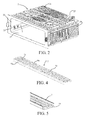
FIG. 1 is a schematic three-dimensional view of a cooling appliance according to a preferable embodiment of the present invention, where a door is not shown; -
FIG. 2 is a schematic three-dimensional view of a box of a storage unit according to a preferable embodiment of the present invention; -
FIG. 3 is a schematic sectional view of a storage unit cut along a center plane perpendicular to an access port of a box according to a preferable embodiment of the present invention; -
FIG. 4 is a schematic three-dimensional view of a reinforcing member according to a preferable embodiment of the present invention; -
FIG. 5 is a schematic partial three-dimensional view of a pretreated reinforcing member according to a preferable embodiment of the present invention, where an end portion of the reinforcing member has an encapsulation portion; -
FIG. 6 is a schematic side view of a reinforcing member according to another preferable embodiment of the present invention; -
FIG. 7 is a schematic side view of a reinforcing member according to another preferable embodiment of the present invention; and -
FIG. 8 is a schematic partial sectional view of a storage unit according to another preferable embodiment of the present invention. -
FIG. 1 is a three-dimensional view of acooling appliance 100 according to a preferable embodiment of the present invention, where a door is not shown. As shown inFIG. 1 , thecooling appliance 100 includes a thermally insulatingmain body 101 having a plurality ofstorage chambers storage chambers main body 101. - The
cooling appliance 100 includes a low-pressure storage unit 1 located in thestorage chamber 104. Thecooling appliance 100 may include an evacuation device (for example, a vacuum pump) in fluid communication with a storage space, so as to evacuate the sealed storage space of the low-pressure storage unit 1. In an alternative embodiment, the low-pressure storage unit 1 is manually depressurized by a user (for example, through an evacuating tool independent of the cooling appliance) before being stored in thecooling appliance 100, which is also acceptable. - Referring to
FIG. 1 to FIG. 3 , the low-pressure storage unit 1 includes abox 2 having one side provided with anaccess port 20, and a cover wall 3 for selectively opening or closing theaccess port 20. - The cover wall 3 may be connected to the
box 2 by a pair of guide rails 5, so as to slide relative to thebox 2. Atray 11 for storing food may be connected to a rear side of the cover wall 3. By pulling/drawing the cover wall 3, thetray 11 may be pushed into thebox 2 or may be at least partially drawn out of thebox 2. - The
box 2 includes atop wall 21, abottom wall 22, aleft side wall 23, aright side wall 24, and arear wall 25. The walls 21-25 together form a chamber having theaccess port 20. When theaccess port 20 is closed by the cover wall 3 in an airtight manner, thetop wall 21, thebottom wall 22, theleft side wall 23, theright side wall 24, and therear wall 25 of thebox 2, and the cover wall 3 together surround and form anevacuatable storage space 4. In this embodiment, the shape of thestorage space 4 is essentially determined by thebox 2. - The
top wall 21, thebottom wall 22, theleft side wall 23, theright side wall 24, and therear wall 25 are made of plastic. In a preferable embodiment, thetop wall 21, thebottom wall 22, theleft side wall 23, theright side wall 24, and therear wall 25 are made of a polypropylene resin filled with a reinforcing additive. Preferably, thetop wall 21, thebottom wall 22, theleft side wall 23, theright side wall 24, and therear wall 25 are made of a polypropylene resin (PP-TV 30) filled with 30% talcum powder. - The cover wall 3 may also be made of PP-TV30 or may be made of an ABS resin.
- The
box 2 may be integrally formed through injection, so that thetop wall 21, thebottom wall 22, theleft side wall 23, theright side wall 24, and therear wall 25 form an integral structure. - The storage unit 1 includes an evacuating channel 6 for being connected to an evacuating device, and a gas-filling channel (not shown) for filling the evacuated
storage space 4 with air. In an embodiment, the evacuating channel 6 is formed on thebox 2, and the gas-filling channel may be formed on the cover wall 3. - The storage unit 1 is substantially of a flat structure. The
top wall 21 and thebottom wall 22 opposite to one another each have a larger area than the other walls (theleft side wall 23, theright side wall 24, therear wall 25, and the cover wall 3). - When a pressure difference is incurred between the inside and the outside of the
storage space 4 because thestorage space 4 is evacuated, the walls (the walls 3 and 21-25) of thestorage space 4 bear a pressure caused by the pressure difference. The storage unit 1 is provided with a plurality of reinforcingmembers storage space 4. - The reinforcing
members top wall 21 and thebottom wall 22 that have the largest area among the walls forming the outer profile of the storage unit 1 are respectively embedded with at least one reinforcingmember - A Young's modulus of a material made into the reinforcing
members box 2, so as to improve resistance of the reinforcingmembers members - The reinforcing
members box 2 through an insert injection molding method. Specifically, before thebox 2 is formed through injection molding, the reinforcingmembers box 2, and then a material (for example, a resin) for forming thebox 2 is injected, so that the melted material and the reinforcingmembers - In the injection molding process in which the reinforcing
members box 2, the reinforcingmembers members box 2 is completed, the two ends of each of the reinforcingmembers box 2. - Alternatively, each of the reinforcing
members box 2. To achieve this, before the step of forming thebox 2 by injection molding, the two ends of the reinforcingmember member FIG. 5 , and before being placed in the mold for forming thebox 2 through injection molding, two ends of each of the reinforcingmembers encapsulation portion 75. In the insert injection molding process in which the reinforcingmembers box 2, the jig clamps theencapsulation portion 75, so as to fix the reinforcingmembers - In an alternative embodiment, by selecting a suitable mold structure, the reinforcing
member box 2 during the injection molding process of thebox 2. - Because the melted material and the metal insert are joined, after the molding, a very large friction force and bite force are formed between the reinforcing
member box 2, so as to enable the storage unit 1 to achieve required reliability and intensity with less box material. In a preferable embodiment, for the storage unit 1 with a volume being 15 L, the thickness of the part ofbox 2 where is not provided with the reinforcingmember - In an alternative embodiment, the reinforcing
member box 2 through a press-in forming method. Specifically, after being heated, the reinforcingmember box 2 made of plastic. - The
top wall 21, thebottom wall 22, theleft side wall 23, theright side wall 24, and therear wall 25 are integrally formed with many reinforcing ribs 28 protruding outwards from outer surfaces thereof. The reinforcing ribs 28 and the walls 21-25 are integrally formed by using the same material in the injection molding process. - Density distribution of the reinforcing ribs 28 on at least one of the
top wall 21, thebottom wall 22, theleft side wall 23, and theright side wall 24 is uneven. In an easily deformable region of thebox 2, denser reinforcing ribs 28 are distributed, but in a region that is not deformed easily, less reinforcing ribs 28 are distributed, so that less material is used to form thebox 2 while gas leakage incurred by the deformation of thebox 2 is prevented. - For example, on the
top wall 21 and thebottom wall 22, the density (mass) of the reinforcing ribs 28 near a center plane perpendicular to theaccess port 20 is greater than the density (mass) of the reinforcing ribs 28 in an edge region of thetop wall 21 and thebottom wall 22. For another example, the density of the reinforcing ribs 28 in regions, close to theaccess port 20, of the left andright side walls rear wall 25, of the left andright side walls - According to a preferable embodiment of the present invention, one end, close to the access port, of the
top wall 21 and one end, close to the access port, of thebottom wall 22 are embedded with a reinforcingmember 7 and 9 respectively, so as to prevent failure of sealing between thebox 2 and the cover wall 3 incurred by deformation of parts, close to theaccess port 20, of thetop wall 21 and thebottom wall 22. - The
top wall 21 and thebottom wall 22 each have a center line parallel to the access port. In this embodiment, the center lines of thetop wall 21 and thebottom wall 22 are located in a same plane, and the plane is a center cross section A of thebox 2. - At least one reinforcing
member 8 and 10 longitudinally overlaps the center lines of thetop wall 21 and thebottom wall 22, and at least partially intersects with the center cross section A-A. - Referring to
FIG. 2 to FIG. 4 , the reinforcingmembers storage space 4, and essentially extend in thetop wall 21 or thebottom wall 22 along the entire width of thestorage space 4. Therefore, the reinforcingmember top wall 21 or thebottom wall 22 and overlapping theleft side wall 23 and theright side wall 24 connected to thetop wall 21 and thebottom wall 22 in a direction perpendicular to thetop wall 21 or thebottom wall 22, so as to be supported on theleft side wall 23 and theright side wall 24, which is advantageous for increasing the intensity of thebox 2. - It should be understood that, according to different arrangements of the reinforcing member on the storage unit 1, the reinforcing member may also extend along the entire height or depth of the
storage space 4. - The reinforcing
members member 7 as an example. - As shown in
FIG. 3 andFIG. 4 , the reinforcingmember 7 includes a substantially plate-like base plate 71 and a pair ofleg portions 72 each extending from a corresponding side of thebase plate 71 in a bent manner. The reinforcingmember 7 has a constant cross section that is substantially U-shaped. An end of eachleg portion 72 may have aflange 75. - Therefore, the cross section of the reinforcing
member 7 has a plurality of L-shaped portions, for example, an L-shaped portion formed by thebase plate 71 and eachleg portion 72, and an L-shaped portion formed by eachleg portion 72 and the correspondingflange 75. - The
base plate 71, theleg portions 72, and theflanges 75 of the reinforcingmember 7 are all embedded in thetop wall 21 or thebottom wall 22. Preferably, theleg portions 72 and theflanges 75 are at least partially embedded in the corresponding reinforcing rib 28 protruding outwards from an outer surface of thetop wall 21 or thebottom wall 22. - The
base plate 71 has a plurality of protrudingribs 74, so as to have a wavy cross section. Each protrudingrib 74 may extend in a lengthwise direction of thebase plate 71 along the entire length of thebase plate 71. The protrudingribs 74 may be formed on thebase plate 71 by stamping. Adjacent protrudingribs 74 may be parallel and spaced apart from one another by a preset distance. - The reinforcing
member 7 may have at least one throughhole 73 disposed on thebase plate 71. In the insert injection molding process in which the reinforcingmember 7 is embedded in thebox 2, the melted material for forming thebox 2 may flow from one side of thebase plate 71 to the other side through the throughhole 73, and the throughhole 73 is filled with the material of thebox 2. Therefore, possibility that a gap is formed between thebase plate 71 and thebox 2 can be reduced, and the material on two sides of thebase plate 71 may be connected reliably by the material in the throughhole 73, so that it can be expected that thebase plate 71 and the corresponding wall of thebox 2 are gaplessly and closely connected, and the intensity of thebox 2 is increased. - In this embodiment, the reinforcing
members box 2 respectively. However, the present invention is not limited thereto, and for example, in an alternative embodiment, at least one reinforcing member is embedded in at least two walls of thebox 2. For example, as shown inFIG. 6 , a reinforcingmember 7a includes afirst portion 71a embedded in a profile wall of thebox 2 and twosecond portions 72a each extending from a corresponding end of thefirst portion 71a in a bent manner and buried in another profile wall of thebox 2. For another example, as shown inFIG. 7 , a reinforcingmember 7b is box-shaped, and is embedded in at least four walls of thebox 2. - In an embodiment, the reinforcing member may be net-shaped.
- In the above embodiments, the reinforcing
members top wall 21 or thebottom wall 22. However, in an alternative embodiment, at least one reinforcing member is partially embedded in a corresponding profile wall of the storage unit 1. For example, as shown inFIG. 8 , at least onesurface 71c of a reinforcing member 7c is exposed to the outside of a profile wall 21' of the storage unit 1. Anti-rust treatment may be performed on the surface of the reinforcing member 7c that is exposed to the outside. - It is easily understandable that besides the
top wall 21 and thebottom wall 22, the other walls of the storage unit 1 (for example, theleft side wall 23, theright side wall 24, therear side wall 25, and the cover wall 3) may also be embedded with at least one reinforcing member when needed. - Embodiments of single parts and components illustrated with reference to
FIG. 1 to FIG. 8 may be combined in any given manner, so as to achieve advantages of the present invention. In addition, the present invention is not limited to the shown embodiments, and usually other means besides the shown means may also be applied as long as the means can also achieve the same effect.
Claims (18)
- A storage unit (1) for a cooling appliance, comprising a plurality of walls (21-25, 3, 21'), an evacuatable storage space (4) defined by the plurality of walls (21-25, 3, 21'), and at least one reinforcing member (7-9, 7a, 7b, 7c) for reinforcing at least one of the walls (21-25, 3, 21'), characterized in that the at least one reinforcing member (7-9, 7a, 7b, 7c) is at least partially embedded in at least one of the walls (21-25, 3, 21').
- The storage unit according to claim 1, characterized in that the plurality of walls (21-25, 3, 21') forms a box (2) and a cover wall (3), the box (2) has an access port (20) selectively closed and opened by the cover wall (3), and the at least one reinforcing member (7-9, 7a, 7b, 7c) is at least partially embedded in at least one wall (21, 22) of the box (2).
- The storage unit according to claim 1 or 2, characterized in that the plurality of walls (21-25, 3, 21') comprises at least one first wall (21, 22) and at least one second wall (23, 24, 25, 3), wherein the first wall (21, 22) has an area larger than that of the second wall (23, 24, 25, 3), and the at least one reinforcing member (7, 8, 9, 10) is at least partially embedded in the at least one first wall (21, 22).
- The storage unit according to claim 1, 2 or 3, characterized in that the at least one reinforcing member (7, 8, 9, 10) extends in the at least one wall (21, 22) along the entire width, height or depth of the storage space (4).
- The storage unit according to any of the preceding claims, characterized in that the at least one wall (21, 22) is embedded with at least two reinforcing members (7, 8, 9, 10) spaced apart from one another.
- The storage unit according to any of the preceding claims, characterized in that at least one reinforcing member is embedded in at least two of the walls.
- The storage unit according to any of the preceding claims, characterized in that the plurality of walls (21-25, 3, 21') is made of a first material, the at least one reinforcing member (7, 8, 9, 10, 7a, 7b, 7c) is made of a second material, and the second material has a Young's modulus greater than that of the first material.
- The storage unit according to claim 7, characterized in that the first material is plastic and the second material is metal.
- The storage unit according to any of the preceding claims, characterized in that the at least one reinforcing member (7, 8, 9, 10, 7a, 7b, 7c) is bar-shaped, box-shaped or net-shaped.
- The storage unit according to claim 2, characterized in that the at least one reinforcing member (7, 9) is at least partially embedded in at least one wall (21, 22) close to the access port (20), and is adjacent to the access port (20).
- The storage unit according to claim 2, characterized in that the at least one wall (21, 22) has a center line parallel to the access port, and at least one reinforcing member (8, 10) overlaps the center line.
- The storage unit according to any of the preceding claims, characterized in that the at least one reinforcing member (7, 8, 9, 10) is completely sealed in the at least one wall.
- The storage unit according to any of claims 1 to 12, characterized in that at least one end of the reinforcement member (7, 8, 9, 10) is exposed to outside of the at least one wall.
- The storage unit according to any one of the preceding claims , characterized in that a cross section of the at least one reinforcing member (7, 8, 9, 10) has at least one L-shaped portion, and the L-shaped portion is embedded in the at least one wall (21, 22).
- The storage unit according to claim 14, characterized in that the at least one wall (21-25) has a reinforcing rib (28) protruding outwards from an outer surface thereof, and the L-shaped portion is embedded in the reinforcing rib (28).
- The storage unit according to any one of the preceding claims, characterized in that the at least one reinforcing member (7, 8, 9, 10) has at least one protruding rib (74).
- The storage unit according to any one of the preceding claims, characterized in that the at least one reinforcing member (7, 8, 9, 10) has at least one through hole (73), and the through hole (73) is filled with the material of the at least one wall (21-25).
- A cooling appliance (100), characterized by comprising the storage unit (1) according to any one of the above claims.
Applications Claiming Priority (1)
| Application Number | Priority Date | Filing Date | Title |
|---|---|---|---|
| CN201210251225.5A CN103542669B (en) | 2012-07-13 | 2012-07-13 | Refrigerating appliance with storage unit |
Publications (2)
| Publication Number | Publication Date |
|---|---|
| EP2696153A2 true EP2696153A2 (en) | 2014-02-12 |
| EP2696153A3 EP2696153A3 (en) | 2017-02-15 |
Family
ID=48703249
Family Applications (1)
| Application Number | Title | Priority Date | Filing Date |
|---|---|---|---|
| EP13174636.4A Withdrawn EP2696153A3 (en) | 2012-07-13 | 2013-07-02 | Cooling appliance having storage unit |
Country Status (2)
| Country | Link |
|---|---|
| EP (1) | EP2696153A3 (en) |
| CN (1) | CN103542669B (en) |
Families Citing this family (3)
| Publication number | Priority date | Publication date | Assignee | Title |
|---|---|---|---|---|
| CN122029390A (en) * | 2023-09-15 | 2026-05-12 | 尚科宁家运营有限公司 | Thermally insulated container with drawer |
| CN122003567A (en) | 2023-09-15 | 2026-05-08 | 尚科宁家运营有限公司 | Thermally insulated container with drawer |
| US12129099B1 (en) | 2024-03-13 | 2024-10-29 | Sharkninja Operating Llc | Insulated container with a drawer |
Citations (2)
| Publication number | Priority date | Publication date | Assignee | Title |
|---|---|---|---|---|
| CN101324392A (en) | 2007-06-11 | 2008-12-17 | 洪国民 | Pressure regulation system of ultra-low temperature refrigerating device |
| US8052235B2 (en) | 2007-06-06 | 2011-11-08 | Electrolux Home Products, Inc. | Storage compartment |
Family Cites Families (8)
| Publication number | Priority date | Publication date | Assignee | Title |
|---|---|---|---|---|
| CN2245042Y (en) * | 1995-10-31 | 1997-01-15 | 杨念慈 | Beer fresh-keeping barrel with vacuum insulation course |
| JP3263595B2 (en) * | 1996-04-10 | 2002-03-04 | 三洋電機株式会社 | Cooling storage |
| GB2414064B (en) * | 2004-05-13 | 2007-08-15 | Cambridge Consultants | Vacuum storage compartment construction in cooling apparatus |
| GB2414065B (en) * | 2004-05-13 | 2007-08-22 | Cambridge Consultants | Vacuum storage compartment construction in cooling apparatus |
| CN201508098U (en) * | 2009-08-06 | 2010-06-16 | 海尔集团公司 | Refrigeration unit and its full-width storage box storage |
| CN102261801B (en) * | 2010-05-28 | 2015-09-30 | 博西华家用电器有限公司 | For low pressure storage unit and the refrigerating appliance of refrigerating appliance |
| CN102261782B (en) * | 2010-05-28 | 2016-05-11 | 博西华家用电器有限公司 | Refrigerating appliance |
| JP5401416B2 (en) * | 2010-08-24 | 2014-01-29 | 日立アプライアンス株式会社 | refrigerator |
-
2012
- 2012-07-13 CN CN201210251225.5A patent/CN103542669B/en active Active
-
2013
- 2013-07-02 EP EP13174636.4A patent/EP2696153A3/en not_active Withdrawn
Patent Citations (2)
| Publication number | Priority date | Publication date | Assignee | Title |
|---|---|---|---|---|
| US8052235B2 (en) | 2007-06-06 | 2011-11-08 | Electrolux Home Products, Inc. | Storage compartment |
| CN101324392A (en) | 2007-06-11 | 2008-12-17 | 洪国民 | Pressure regulation system of ultra-low temperature refrigerating device |
Also Published As
| Publication number | Publication date |
|---|---|
| EP2696153A3 (en) | 2017-02-15 |
| CN103542669A (en) | 2014-01-29 |
| CN103542669B (en) | 2018-06-12 |
Similar Documents
| Publication | Publication Date | Title |
|---|---|---|
| KR100819085B1 (en) | Refrigerator | |
| JP6091825B2 (en) | refrigerator | |
| US11752669B2 (en) | Method of fabricating 3D vacuum insulated refrigerator structure having core material | |
| CN106766534B (en) | Insulation boxes and refrigeration equipment for refrigeration equipment | |
| CN102645075B (en) | Mounting structure for middle beam of freezer | |
| WO2011147900A2 (en) | Sealing system and household appliance having the sealing system | |
| CN105135796A (en) | Door for a household appliance and household appliance | |
| US10030905B2 (en) | Method of fabricating a vacuum insulated appliance structure | |
| RU2013151028A (en) | REFRIGERATING UNIT, IN PARTICULAR HOUSEHOLD REFRIGERATING UNIT | |
| WO2013042338A2 (en) | Refrigerator | |
| CN105135804A (en) | refrigerator | |
| JP7449009B2 (en) | refrigerator | |
| CN103542669B (en) | Refrigerating appliance with storage unit | |
| CN203478820U (en) | Refrigerator | |
| CN102261794B (en) | Household electrical appliance | |
| JP3871500B2 (en) | Refrigerator door | |
| WO2011147899A2 (en) | Low-pressure storage unit for refrigeration appliance and refrigeration appliance | |
| AU2015407161A1 (en) | Vacuum heat-insulating material and refrigerator | |
| JP7569572B2 (en) | refrigerator | |
| JP5670722B2 (en) | Cooling storage | |
| CN204705096U (en) | Vacuum heat-insulation parts and refrigerator | |
| US20190137164A1 (en) | Heat insulation box manufacturing method and heat insulation box | |
| WO2022012175A1 (en) | Heat preservation sealing door and refrigerator | |
| CN102261801B (en) | For low pressure storage unit and the refrigerating appliance of refrigerating appliance | |
| CN105371569B (en) | Cabinet bottom plate |
Legal Events
| Date | Code | Title | Description |
|---|---|---|---|
| AK | Designated contracting states |
Kind code of ref document: A2 Designated state(s): AL AT BE BG CH CY CZ DE DK EE ES FI FR GB GR HR HU IE IS IT LI LT LU LV MC MK MT NL NO PL PT RO RS SE SI SK SM TR |
|
| AX | Request for extension of the european patent |
Extension state: BA ME |
|
| PUAI | Public reference made under article 153(3) epc to a published international application that has entered the european phase |
Free format text: ORIGINAL CODE: 0009012 |
|
| RAP1 | Party data changed (applicant data changed or rights of an application transferred) |
Owner name: BSH HAUSGERAETE GMBH |
|
| PUAL | Search report despatched |
Free format text: ORIGINAL CODE: 0009013 |
|
| AK | Designated contracting states |
Kind code of ref document: A3 Designated state(s): AL AT BE BG CH CY CZ DE DK EE ES FI FR GB GR HR HU IE IS IT LI LT LU LV MC MK MT NL NO PL PT RO RS SE SI SK SM TR |
|
| AX | Request for extension of the european patent |
Extension state: BA ME |
|
| RIC1 | Information provided on ipc code assigned before grant |
Ipc: F25D 25/02 20060101ALI20170109BHEP Ipc: F25D 17/04 20060101AFI20170109BHEP Ipc: F25D 23/06 20060101ALI20170109BHEP |
|
| 17P | Request for examination filed |
Effective date: 20170816 |
|
| RBV | Designated contracting states (corrected) |
Designated state(s): AL AT BE BG CH CY CZ DE DK EE ES FI FR GB GR HR HU IE IS IT LI LT LU LV MC MK MT NL NO PL PT RO RS SE SI SK SM TR |
|
| STAA | Information on the status of an ep patent application or granted ep patent |
Free format text: STATUS: THE APPLICATION HAS BEEN WITHDRAWN |
|
| 18W | Application withdrawn |
Effective date: 20190207 |