EP2696030A1 - Turbine vane - Google Patents
Turbine vane Download PDFInfo
- Publication number
- EP2696030A1 EP2696030A1 EP12768226.8A EP12768226A EP2696030A1 EP 2696030 A1 EP2696030 A1 EP 2696030A1 EP 12768226 A EP12768226 A EP 12768226A EP 2696030 A1 EP2696030 A1 EP 2696030A1
- Authority
- EP
- European Patent Office
- Prior art keywords
- vane
- hole
- turbine
- cooling
- film cooling
- Prior art date
- Legal status (The legal status is an assumption and is not a legal conclusion. Google has not performed a legal analysis and makes no representation as to the accuracy of the status listed.)
- Granted
Links
Images




Classifications
-
- F—MECHANICAL ENGINEERING; LIGHTING; HEATING; WEAPONS; BLASTING
- F01—MACHINES OR ENGINES IN GENERAL; ENGINE PLANTS IN GENERAL; STEAM ENGINES
- F01D—NON-POSITIVE DISPLACEMENT MACHINES OR ENGINES, e.g. STEAM TURBINES
- F01D5/00—Blades; Blade-carrying members; Heating, heat-insulating, cooling or antivibration means on the blades or the members
- F01D5/12—Blades
- F01D5/14—Form or construction
- F01D5/18—Hollow blades, i.e. blades with cooling or heating channels or cavities; Heating, heat-insulating or cooling means on blades
- F01D5/186—Film cooling
-
- F—MECHANICAL ENGINEERING; LIGHTING; HEATING; WEAPONS; BLASTING
- F05—INDEXING SCHEMES RELATING TO ENGINES OR PUMPS IN VARIOUS SUBCLASSES OF CLASSES F01-F04
- F05D—INDEXING SCHEME FOR ASPECTS RELATING TO NON-POSITIVE-DISPLACEMENT MACHINES OR ENGINES, GAS-TURBINES OR JET-PROPULSION PLANTS
- F05D2250/00—Geometry
- F05D2250/10—Two-dimensional
- F05D2250/12—Two-dimensional rectangular
-
- F—MECHANICAL ENGINEERING; LIGHTING; HEATING; WEAPONS; BLASTING
- F05—INDEXING SCHEMES RELATING TO ENGINES OR PUMPS IN VARIOUS SUBCLASSES OF CLASSES F01-F04
- F05D—INDEXING SCHEME FOR ASPECTS RELATING TO NON-POSITIVE-DISPLACEMENT MACHINES OR ENGINES, GAS-TURBINES OR JET-PROPULSION PLANTS
- F05D2250/00—Geometry
- F05D2250/10—Two-dimensional
- F05D2250/14—Two-dimensional elliptical
-
- F—MECHANICAL ENGINEERING; LIGHTING; HEATING; WEAPONS; BLASTING
- F05—INDEXING SCHEMES RELATING TO ENGINES OR PUMPS IN VARIOUS SUBCLASSES OF CLASSES F01-F04
- F05D—INDEXING SCHEME FOR ASPECTS RELATING TO NON-POSITIVE-DISPLACEMENT MACHINES OR ENGINES, GAS-TURBINES OR JET-PROPULSION PLANTS
- F05D2250/00—Geometry
- F05D2250/50—Inlet or outlet
- F05D2250/52—Outlet
-
- F—MECHANICAL ENGINEERING; LIGHTING; HEATING; WEAPONS; BLASTING
- F05—INDEXING SCHEMES RELATING TO ENGINES OR PUMPS IN VARIOUS SUBCLASSES OF CLASSES F01-F04
- F05D—INDEXING SCHEME FOR ASPECTS RELATING TO NON-POSITIVE-DISPLACEMENT MACHINES OR ENGINES, GAS-TURBINES OR JET-PROPULSION PLANTS
- F05D2250/00—Geometry
- F05D2250/70—Shape
-
- F—MECHANICAL ENGINEERING; LIGHTING; HEATING; WEAPONS; BLASTING
- F05—INDEXING SCHEMES RELATING TO ENGINES OR PUMPS IN VARIOUS SUBCLASSES OF CLASSES F01-F04
- F05D—INDEXING SCHEME FOR ASPECTS RELATING TO NON-POSITIVE-DISPLACEMENT MACHINES OR ENGINES, GAS-TURBINES OR JET-PROPULSION PLANTS
- F05D2260/00—Function
- F05D2260/20—Heat transfer, e.g. cooling
- F05D2260/202—Heat transfer, e.g. cooling by film cooling
-
- Y—GENERAL TAGGING OF NEW TECHNOLOGICAL DEVELOPMENTS; GENERAL TAGGING OF CROSS-SECTIONAL TECHNOLOGIES SPANNING OVER SEVERAL SECTIONS OF THE IPC; TECHNICAL SUBJECTS COVERED BY FORMER USPC CROSS-REFERENCE ART COLLECTIONS [XRACs] AND DIGESTS
- Y02—TECHNOLOGIES OR APPLICATIONS FOR MITIGATION OR ADAPTATION AGAINST CLIMATE CHANGE
- Y02T—CLIMATE CHANGE MITIGATION TECHNOLOGIES RELATED TO TRANSPORTATION
- Y02T50/00—Aeronautics or air transport
- Y02T50/60—Efficient propulsion technologies, e.g. for aircraft
Definitions
- the present invention relates to a turbine vane used in a turbine for gas turbine engines such as an aircraft engine and an industrial gas turbine engine.
- turbine vanes to be exposed to a combustion gas while a gas turbine engine is in operation can be cooled by use of cooling air (part of compressed air) extracted from a compressor or a fan of the gas turbine engine.
- a cooling passage into which the cooling air can flow is formed inside the turbine vane, and multiple film cooling holes through which the cooling air can jet out are formed in a vane surface of the turbine vane in such a way as to communicate with the cooling passage. For this reason, while the gas turbine engine is in operation, the cooling air flowing into the cooling passage is jetted out through the multiple film cooling holes, thus forms a film cooling layer which covers the vane surface of the turbine vane, and can perform film cooling on the turbine vane.
- an object of the present invention is to provide a turbine vane having a novel configuration which is capable of fully cooling a front edge-side vane surface and its vicinity.
- An aspect of the present invention is a turbine vane for a turbine of a gas turbine engine, and capable of being cooled by cooling air, the turbine vane comprising: a vane body including: a vane surface; a cooling passage allowing the cooling air to flow into the vane body; and a plurality of film cooling holes formed in the vane surface on a front edge side of the vane body so as to communicate with the cooling passage to jet out the cooling air through the plurality of film cooling holes, a hole cross section of each film cooling hole having a long-hole shape extending in a direction parallel to a cross section along a span direction of the vane body, a hole-center line of each film cooling hole tilting from a thickness direction of the vane body on a cross section of the vane surface along the span direction, and an exit-side and obtuse angle-side portion of a hole wall surface of each film cooling hole tilting further from the thickness direction than the hole-center line on the cross section along the span direction.
- the “turbine vane” represents a turbine rotor vane and a turbine stator vane
- the “hole cross section” means a cross section perpendicular to the hole-center line.
- the "exit side” represents the exit side viewed in the flowing direction of the cooling air
- the "obtuse angle side” represents a side (region) having an obtuse angle defined with the vane surface.
- the present invention makes it possible to fully diffuse the cooling air, which is jetted out through each film cooling hole, on the front edge-side vane surface of the turbine vane in the span direction while inhibiting the cooling air from coming up away from the front edge-side vane surface of the turbine vane. For this reason, it is possible to increase the film efficiency around the front edge-side vane surface of the turbine vane, and accordingly to increase the cooling performance of the turbine vane to a higher level.
- reference sign "FF" denotes a frontward direction
- reference sign "FR” denotes a rearward direction.
- the frontward direction means an upstream direction in the light of a flowing direction of a main stream
- the rearward direction means a downstream direction in the light of the flowing direction of the main stream.
- a turbine stator vane 1 of the embodiment is used for a turbine (not shown) of a gas turbine engine such as an aircraft engine and an industrial gas turbine engine.
- the turbine stator vane 1 can be cooled by cooling air (part of compressed air) CA extracted from a compressor (not shown) or a fan (not shown) of the gas turbine engine.
- the specific configuration of the turbine stator vane 1 is as follows.
- the turbine stator vane 1 is produced (cast) by lost wax precision casting, for example.
- the turbine stator vane 1 includes a hollow stator vane body (vane body) 3.
- a rib wall (partition wall) 5 is provided inside the stator vane body 3.
- the rib wall 5 divides the inside of the stator vane body 3 into front and rear halves, and forms a front cooling passage 7 and a rear cooling passage 9 into which the cooling air CA can flow.
- the front cooling passage 7 is formed in the front half of the stator vane body 3
- the rear cooling passage 9 is formed in the rear half of the stator vane body 3.
- the stator vane body 3 has a vane surface 3a in its front edge-side portion.
- Multiple film cooling holes 11 are formed in the vane surface 3a so as to communicate with the front cooling passage 7.
- the cooling air CA which flows into the front cooling passage 7 is jetted out through the film cooling holes 11.
- the stator vane body 3 has a vane surface 3v in its flank portion. Multiple film cooling holes 13 are formed in the vane surface 3v so as to communicate with the front cooling passage 7 or the rear cooling passage 9. The cooling air CA which flows into the front cooling passage 7 or the rear cooling passage 9 is jetted out through the film cooling holes 13.
- the stator vane body 3 further has a vane surface 3p in its rear edge-side portion. Multiple film cooling holes 15 are formed in the vane surface 3p so as to communicate with the rear cooling passage 9. The cooling air CA which flows into the rear cooling passage 9 is jetted out through the film cooling holes 15.
- the stator vane body 3 has a vane surface 3b in its back portion.
- Multiple film cooling holes (not shown) similar to the film cooling holes 11, the film cooling holes 13 and the film cooling holes 15 may be formed in the vane surface 3b.
- the film cooling holes are formed communicating with the front cooling passage 7 or the rear cooling passage 9 in the same way that has been described. The cooling air which flows into the front cooling passage 7 or the rear cooling passage 9 is jetted out through the film cooling holes (not shown).
- an arc-shaped inner band 17 is integrally formed on a base-side portion of the stator vane body 3 in a span direction SD.
- an arc-shaped outer band 19 is integrally formed on a tip-side portion of the stator vane body 3 in the span direction SD.
- a front insertion hole 21 is formed in the outer band 19 so as to be aligned with the front cooling passage 7 of the stator vane body 3.
- a rear insertion hole 23 is formed in the outer band 19 so as to be aligned with the rear cooling passage 9 of the stator vane body 3.
- the front insertion hole 21 is formed in the front half of the outer band 19, and the rear insertion hole 23 is formed in the rear half of the outer band 19.
- the front insertion hole 21 communicates with the front cooling passage 7 of the stator vane body 3, and the rear insertion hole 23 communicates with the rear cooling passage 9 of the stator vane body 3.
- a pipe-shaped front insert 25 is arranged in the front cooling passage 7 of the stator vane body 3.
- the upper portion of the front insert 25 is inserted into the front insertion hole 21 of the outer band 19.
- Multiple front impingement cooling holes 27 are formed in the outer peripheral surface of the front insert 25.
- the cooling air CA is jetted out to the inner wall surface of the front cooling passage 7 through the front impingement cooling holes 27.
- a pipe-shaped rear insert 29 is arranged in the rear cooling passage 9 of the stator vane body 3.
- the upper portion of the rear insert 29 is inserted into the rear insertion hole 23 of the outer band 19.
- Multiple rear impingement cooling holes 31 are formed in the outer peripheral surface of the rear insert 29.
- the cooling air CA is jetted out to the inner wall surface of the rear cooling passage 9 of the stator vane body 3 through the rear impingement cooling holes 31.
- an entrance-side opening and an exit-side opening of each film cooling hole 11 have a rectangular long-hole shape extending in the span direction SD, and having rounded corners.
- the hole cross section of each of the film cooling holes 11 has a rectangular long-hole shape extending in a direction PD parallel to the cross section along the span direction SD, and having rounded corners. It should be noted that the cross section shown in Fig. 4(b) is perpendicular to a hole-center line 11c of the film cooling hole 11.
- the aspect ratio of the hole cross section of each film cooling hole 11 (or the ratio of the long side to the short side of the long hole viewed on the assumption that there are no rounded corners) is set in a range of 1.1 to 3.0, and preferably in a range of 1.5 to 2.5.
- the reason for this is that: if the aspect ratio is less than 1.1, it is difficult to fully diffuse the cooling air CA, which is jetted out through each film cooling hole 11, on the vane surface 3a in the span direction SD; and if the aspect ratio is greater than 3.0, it is difficult to process each film cooling hole 11 (for example, by electrical discharge machining).
- the hole-center line 11c of each film cooling hole 11 tilts from a thickness direction TD of the stator vane body 3 on the cross section along the span direction SD (the cross section parallel to the span direction SD).
- a tilt angle ⁇ c of each hole-center line 11c from the thickness direction TD is set in a range of 20° to 60° or preferably in a range of 30° to 50°.
- An exit-side and obtuse angle-side portion (predetermined exit-side portion) 11e on the hole wall surface of each film cooling hole 11 tilts further to the span direction SD (or the vane surface 3c) than the hole-center line 11c of the film cooling hole 11 on the cross section along the span direction SD.
- a tilt angle ⁇ e of the predetermined exit-side portion 11e of the hole wall surface of each film cooling hole 11 to the span direction SD (or the vane surface 3a) is in a range of 5° to 20° or preferably in a range of 5° to 10°.
- the reason for this is that: if the tilt angle ⁇ e is less than 5°, it is not possible to fully diffuse the cooling air CA in the span direction SD; and if the tilt angle ⁇ e is greater than 20°, the stream is more likely to separate inside the hole wall surface of the film cooling hole 11, and the cooling performance accordingly deteriorates.
- the cooling air CA flowing into the front insert 25 is jetted out to the inner wall surface of the front cooling passage 7 of the stator vane body 3 through the multiple front impingement cooling holes 27, and the cooling air CA flowing into the rear insert 29 is jetted out to the inner wall surface of the rear cooling passage 9 of the stator vane body 3 through the multiple rear impingement cooling holes 31.
- the impingement cooling inner cooling can be performed on the turbine stator vane 1 (the stator vane body 3).
- the cooling air CA contributing to the impingement cooling of the turbine stator vane 1 in other words, the cooling air CA flowing into the front cooling passage 7 and the rear cooling passage 9 of the stator vane body 3 is jetted out through the multiple film cooling holes 11, the multiple film cooling holes 13 and the multiple film cooling holes 15.
- the cooling air CA forms a film cooling layer (not shown) covering the front edge-side vane surface 3a, the flank-side vane surface 3v, and the like of the stator vane body 3 of the turbine stator vane 1, and can perform the film cooling on the turbine stator vane 1.
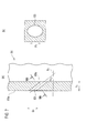
- Fig. 5(a) is a cross-sectional view of a front edge-side vane surface 41a of a turbine vane 41 of the embodiment of the present invention which was simulated in the above-mentioned analysis, the cross-sectional view taken along a span direction S 1 .
- Fig. 5 (b) is a cross-sectional view taken along a VB-VB line in Fig 5(a) . This cross section is perpendicular to a hole-center line 43c of a film cooling hole 43.
- the film cooling hole 43 is formed in the front edge-side vane surface 41a of the turbine vane 41 (see Fig. 8 ).
- the hole-center line 43c of the film cooling hole 43 tilts from a thickness direction T 1 of the turbine vane 41 at the above-mentioned tilt angle ⁇ c on the cross section along the span direction S 1 .
- an exit-side and obtuse angle-side portion (predetermined exit-side portion) of the hole wall surface of the film cooling hole 43 tilts to the span direction S 1 at the above-mentioned tilt angle ⁇ e, and tilts further to the span direction S 1 than the hole center line 43c.
- the film cooling hole 43 has a substantially rectangular cross section extending in a direction P 1 in parallel to the cross section along the span direction S 1 .
- the film cooling hole 43 is a substantially rectangular long hole extending in the direction P 1 .
- Fig. 6 (a) is a cross-sectional view of a front edge-side vane surface 51a of a turbine vane 51 (see Fig. 8 ) as Comparative Example 1 which was simulated in the above-mentioned analysis, the cross-sectional view taken along a span direction S 2 .
- Fig. 6(b) is a cross-sectional view of the front edge-side vane surface 51a taken along a VIB-VIB line in Fig. 6(a) . It should be noted that this cross section is perpendicular to a hole-center line 53c of a film cooling hole 53.
- the film cooling hole 53 is formed in the front edge-side vane surface 51a of the turbine vane 51.
- the hole-center line 53a of the film cooling hole 53 tilts from a thickness direction T 2 of the turbine vane 51 at the predetermined angle ⁇ c on the cross section along the span direction S 2 .
- the film cooling hole 53 has a circular cross section on a plane perpendicular to the hole-center line 53c. It should be noted that the area of this circle is equal to the cross-sectional area of the film cooling hole 43 shown in Fig. 5(b) .
- Fig. 7 (a) is a cross-sectional view of a front edge-side vane surface 61a of a turbine vane 61 (see Fig. 8 ) as Comparative Example 2 which was simulated in the above-mentioned analysis, the cross-sectional view taken along a span direction S 3 .
- Fig. 7(b) is a cross-sectional view of the front edge-side vane surface 61a taken along a VIIB-VIIB line in Fig. 7(a) . It should be noted that this cross section is perpendicular to a hole-center line 63c of a film cooling hole 63.
- the film cooling hole 63 is formed in the front edge-side vane surface 61a of the turbine vane 61.
- the hole-center line 63a of the film cooling hole 63 tilts from a thickness direction T 3 of the turbine vane 61 at the predetermined angle ⁇ c on the cross section along the span direction S 3 .
- the film cooling hole 63 has an elliptical cross section having a major axis along a direction P 3 on a plane perpendicular to the hole-center line 63c.
- the direction P 3 is in parallel to a cross section taken along the span direction S 3 . It should be noted that the area of this ellipse is equal to the cross-sectional area of the film cooling hole 43 shown in Fig. 5(b) .
- Figs. 9(a) to 9(c) , Figs. 10(a) to 10 (c) and Figs. 11 (a) to 11(c) show results of the analysis using the three-dimensional steady-state viscosity CFD.
- Figs. 9(a) to 9 (c) show temperature distributions around the front edge-side vane surface of the turbine vane 41 of the embodiment.
- Figs. 10 (a) to 10 (c) show temperature distributions around the front edge-side vane surface of the turbine vane 51 as Comparative Example 1.
- Figs. 11 (a) to 11 (c) show temperature distributions around the front edge-side vane surface of the turbine vane 61 as Comparative Example 2.
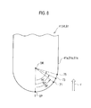
- FIG. 10(a) and Fig. 11(a) show the temperature distributions at the position 71 (see Fig. 8 ) which was displaced downstream of the stagnation point SP at 55° in the direction of the main flow F.
- Fig. 9(b) , Fig. 10(b) and Fig. 11(b) show the temperature distributions at a position 73 (see Fig. 8 ) which was displaced downstream of the stagnation point SP at 65°.
- Fig. 9(c) , Fig. 10(c) and Fig. 11(c) show the temperature distributions at a position 75 (see Fig. 8 ) which was displaced downstream of the stagnation point SP at 75°.
- the Reynolds number and the blow ratio were approximately 9 ⁇ 10 4 and 2.0, respectively, around the front edge-side vane surface.
- an area H represents a high-temperature area corresponding to the combustion gas.
- an area M represents an area where the mixture of the combustion gas and the cooling gas jetted out through the film cooling hole 43 (53, 63) does not progress so much. In other words, the heat exchange does not progress fully between the combustion gas and the cooling gas in the area M. For this reason, the temperature of the area M is lower than that of the area H.
- an area L represents an area where the mixture of the cooling gas and the combustion gas progresses even less than the area M. For this reason, the temperature of the area L is lower than that of the area M.
- Fig. 12 shows a result of an analysis on average film efficiencies of the cooling gas around the front edge-side vane surface along the span direction which was obtained from another three-dimensional steady-state viscosity CFD analysis.
- the film efficiency is defined as (Tg-Tf)/(Tg-Tc), where: Tg denotes the temperature of the combustion gas; Tf denotes the temperature of the film cooling layer; and Tc denotes the temperature of the cooling air CA.
- the conditions for this analysis are the same as those for the foregoing analysis. That is to say, it was assumed that the Reynolds number and the blow ratio were approximately 9 ⁇ 10 4 and 2.0, respectively, around the front edge-side vane surface.
- a solid line indicates a change in average film efficiency ⁇ 1 of the turbine vane 41 (see Fig. 5(a) and Fig. 5(b) ) of the embodiment which was used in the analysis.
- a dotted line indicates a change in average film efficiency ⁇ 2 of the turbine vane 51 (see Fig. 6(a) and Fig. 6(b) ) of Comparative Example 1.
- a chain dashed line indicates a change in average film efficiency ⁇ 3 of the turbine vane 61 (see Fig. 7(a) and Fig. 7(b) ) of Comparative Example 2.
- the horizontal axis of the graph shown in Fig. 12 represents the distance of the front edge-side vane surface from the stagnation point SP.
- the distance is converted into a dimensionless distance by dividing the distance by the equivalent diameter of the hole cross section of the film cooling hole (the diameter of a circular hole having the same cross-sectional area). It can be learned from this graph that: the average film efficiency ⁇ 1 of the turbine vane 41 of the embodiment is sufficiently higher than the average film efficiencies ⁇ 2 , ⁇ 3 of the turbine vanes 51, 61 of Comparative Examples 1 and 2; and this tendency can be obtained regardless of how long the distance is.
- the hole cross section of each film cooling hole 11 is shaped like a long hole extending in the direction PD parallel to the cross section along the span direction SD.
- the hole-center line 11c of each film cooling hole 11 tilts from the thickness direction TD on the cross section along the span direction SD.
- the predetermined exit-side portion 11e of the hole wall surface of each film cooling hole 11 tilts further from the thickness direction TD than the hole-center line 11c on the cross section along the span direction SD.
- each film cooling hole 11 is capable of more fully diffusing the cooling air CA, which is jetted out through the film cooling hole 11, on the vane surface 3a of the stator vane body 3 in the span direction SD while inhibiting the cooling air CA from coming up (separating) away from the vane surface 3a than the case where the cross-sectional of the film cooling hole 11 would be shaped like a circle or an ellipse.
- the embodiment makes it possible to increase the film efficiency around the vane surface 3a of the stator vane body 3 of the turbine stator vane 1, and accordingly to increase the cooling performance of the turbine stator vane 1 to a higher level.
- the present invention is not limited to what has been described for the embodiment.
- the present invention can be carried out in other various modes including, for example, a mode where the technical idea applied to the turbine stator vane 1 is applied to a turbine rotor vane. What is more, the scope of the right included in the present invention is not limited to these embodiments.
- the invention makes it possible to fully diffuse the cooling air, which is jetted out through the film cooling holes, on the front edge-side vane surface of the turbine vane in the span direction of the turbine vane while inhibiting the cooling air from coming up away from the vane surface.
- it is possible to increase the film efficiency around the front edge-side vane surface of the turbine vane and to increase the cooling performance of the turbine stator vane to a higher level.
Landscapes
- Engineering & Computer Science (AREA)
- Mechanical Engineering (AREA)
- General Engineering & Computer Science (AREA)
- Turbine Rotor Nozzle Sealing (AREA)
Abstract
Description
- The present invention relates to a turbine vane used in a turbine for gas turbine engines such as an aircraft engine and an industrial gas turbine engine.
- In general, turbine vanes to be exposed to a combustion gas while a gas turbine engine is in operation can be cooled by use of cooling air (part of compressed air) extracted from a compressor or a fan of the gas turbine engine.
- To put it specifically, a cooling passage into which the cooling air can flow is formed inside the turbine vane, and multiple film cooling holes through which the cooling air can jet out are formed in a vane surface of the turbine vane in such a way as to communicate with the cooling passage. For this reason, while the gas turbine engine is in operation, the cooling air flowing into the cooling passage is jetted out through the multiple film cooling holes, thus forms a film cooling layer which covers the vane surface of the turbine vane, and can perform film cooling on the turbine vane.
- Conventional techniques related to the present invention have been disclosed in
PTL 1 and PTL 2. -
- [PTL 1]
JP 2009-162224 A - [PTL 2]
JP 07-063002 A - In recent years, there has been increasing demand for higher output from gas turbine engines. To meet the demand, the temperature of a combustion gas tends to become very high at an entrance-side portion of a turbine. Against this background, it is imperative to increase the cooling performance of the turbine vane to a higher level by increasing film efficiency on the vane surface of the turbine vane, particularly around a front edge-side vane surface of the turbine vane (including the front edge-side vane surface) where the temperature of the component is apt to rise due to collisions of the combustion gas.
- With this taken into consideration, an object of the present invention is to provide a turbine vane having a novel configuration which is capable of fully cooling a front edge-side vane surface and its vicinity.
- An aspect of the present invention is a turbine vane for a turbine of a gas turbine engine, and capable of being cooled by cooling air, the turbine vane comprising: a vane body including: a vane surface; a cooling passage allowing the cooling air to flow into the vane body; and a plurality of film cooling holes formed in the vane surface on a front edge side of the vane body so as to communicate with the cooling passage to jet out the cooling air through the plurality of film cooling holes, a hole cross section of each film cooling hole having a long-hole shape extending in a direction parallel to a cross section along a span direction of the vane body, a hole-center line of each film cooling hole tilting from a thickness direction of the vane body on a cross section of the vane surface along the span direction, and an exit-side and obtuse angle-side portion of a hole wall surface of each film cooling hole tilting further from the thickness direction than the hole-center line on the cross section along the span direction.
- In the description and scope of claims of this application, the "turbine vane" represents a turbine rotor vane and a turbine stator vane, and the "hole cross section" means a cross section perpendicular to the hole-center line. Furthermore, the "exit side" represents the exit side viewed in the flowing direction of the cooling air, and the "obtuse angle side" represents a side (region) having an obtuse angle defined with the vane surface.
- The present invention makes it possible to fully diffuse the cooling air, which is jetted out through each film cooling hole, on the front edge-side vane surface of the turbine vane in the span direction while inhibiting the cooling air from coming up away from the front edge-side vane surface of the turbine vane. For this reason, it is possible to increase the film efficiency around the front edge-side vane surface of the turbine vane, and accordingly to increase the cooling performance of the turbine vane to a higher level.
-
- [
Fig. 1] Fig. 1 is a perspective view of a turbine stator vane of an embodiment of the present invention. - [
Fig. 2] Fig. 2 is a side view of the turbine stator vane of the embodiment of the present invention, which is partially cut away. - [
Fig. 3] Fig. 3 is a magnified cross-sectional view of the turbine stator vane taken along a III-III line inFig. 2 . - [
Fig. 4] Fig. 4(a) is a cross-sectional view of a part of a front edge-side vane surface of the turbine stator vane of the embodiment of the present invention, which extends in a span direction;Fig. 4 (b) is a magnified cross-sectional view taken along a IVB-IVB line inFig. 4 (a) ; Fig. 4 (c) is a magnified view of a portion viewed in a direction indicated with an arrow IVC inFig. 4(a); and Fig. 4(d) is a magnified view of a portion viewed in a direction indicated with an arrow IVD inFig. 4(a) . - [
Fig. 5] Fig. 5(a) is a cross-sectional view of a front edge-side portion of a turbine vane of Invention Example, and -
Fig. 5(b) is a cross-sectional view taken along a VB-VB line inFig. 5(a) . - [
Fig. 6] Fig. 6(a) is a cross-sectional view of a front edge-side portion of a turbine vane of Comparative Example 1, andFig. 6(b) is a cross-sectional view taken along a XIB-VIB line inFig. 6(a) . - [
Fig. 7] Fig. 7(a) is a cross-sectional view of a front edge-side portion of a turbine vane of Comparative Example 2, andFig. 7 (b) is a cross-sectional view taken along a XIIB-VIIB line inFig. 7(a) . - [
Fig. 8] Fig. 8 is a schematic diagram for explaining a stagnation point and the like on the front edge-side vane surface of the turbine vane. - [
Fig. 9] Figs. 9(a), 9(b) and 9(c) are diagrams showing how the temperature is distributed around the front edge-side vane surface of the turbine vane of Invention Example. - [
Fig. 10] Figs. 10(a), 10(b) and 10(c) are diagrams showing how the temperature is distributed around the front edge-side vane surface of the turbine vane of Comparative Example 1. - [
Fig. 11] Figs. 11(a), 11(b) and 11(c) are diagrams showing how the temperature is distributed around the front edge-side vane surface of the turbine vane of Comparative Example 2. - [
Fig. 12] Fig. 12 is a diagram showing relationships between the distance from the stagnation point on the front edge-side vane surface and film efficiency regarding the turbine vane of Invention Example, the turbine vane of Comparative Example 1 and the turbine vane of Comparative Example 2. - Descriptions will be provided for an embodiment of the present invention by referring to
Fig. 1 to Fig. 4 . It should be noted that in the drawings, reference sign "FF" denotes a frontward direction and reference sign "FR" denotes a rearward direction. The frontward direction means an upstream direction in the light of a flowing direction of a main stream, and the rearward direction means a downstream direction in the light of the flowing direction of the main stream. - As shown in
Figs. 1 ,2 and3 , aturbine stator vane 1 of the embodiment is used for a turbine (not shown) of a gas turbine engine such as an aircraft engine and an industrial gas turbine engine. Theturbine stator vane 1 can be cooled by cooling air (part of compressed air) CA extracted from a compressor (not shown) or a fan (not shown) of the gas turbine engine. The specific configuration of theturbine stator vane 1 is as follows. - The turbine stator vane 1 is produced (cast) by lost wax precision casting, for example. As shown in
Fig. 1 , theturbine stator vane 1 includes a hollow stator vane body (vane body) 3. A rib wall (partition wall) 5 is provided inside thestator vane body 3. The rib wall 5 divides the inside of thestator vane body 3 into front and rear halves, and forms a front cooling passage 7 and a rear cooling passage 9 into which the cooling air CA can flow. In other words, the front cooling passage 7 is formed in the front half of thestator vane body 3, and the rear cooling passage 9 is formed in the rear half of thestator vane body 3. - As shown in
Fig. 1 , thestator vane body 3 has avane surface 3a in its front edge-side portion. Multiplefilm cooling holes 11 are formed in thevane surface 3a so as to communicate with the front cooling passage 7. The cooling air CA which flows into the front cooling passage 7 is jetted out through thefilm cooling holes 11. - The
stator vane body 3 has avane surface 3v in its flank portion. Multiplefilm cooling holes 13 are formed in thevane surface 3v so as to communicate with the front cooling passage 7 or the rear cooling passage 9. The cooling air CA which flows into the front cooling passage 7 or the rear cooling passage 9 is jetted out through thefilm cooling holes 13. - The
stator vane body 3 further has avane surface 3p in its rear edge-side portion. Multiplefilm cooling holes 15 are formed in thevane surface 3p so as to communicate with the rear cooling passage 9. The cooling air CA which flows into the rear cooling passage 9 is jetted out through thefilm cooling holes 15. - The
stator vane body 3 has avane surface 3b in its back portion. Multiple film cooling holes (not shown) similar to thefilm cooling holes 11, thefilm cooling holes 13 and thefilm cooling holes 15 may be formed in thevane surface 3b. In this case, too, the film cooling holes are formed communicating with the front cooling passage 7 or the rear cooling passage 9 in the same way that has been described. The cooling air which flows into the front cooling passage 7 or the rear cooling passage 9 is jetted out through the film cooling holes (not shown). - As shown in
Fig. 2 , an arc-shapedinner band 17 is integrally formed on a base-side portion of thestator vane body 3 in a span direction SD. In addition, an arc-shapedouter band 19 is integrally formed on a tip-side portion of thestator vane body 3 in the span direction SD. Afront insertion hole 21 is formed in theouter band 19 so as to be aligned with the front cooling passage 7 of thestator vane body 3. Meanwhile, arear insertion hole 23 is formed in theouter band 19 so as to be aligned with the rear cooling passage 9 of thestator vane body 3. In other words, thefront insertion hole 21 is formed in the front half of theouter band 19, and therear insertion hole 23 is formed in the rear half of theouter band 19. Moreover, thefront insertion hole 21 communicates with the front cooling passage 7 of thestator vane body 3, and therear insertion hole 23 communicates with the rear cooling passage 9 of thestator vane body 3. - A pipe-shaped
front insert 25 is arranged in the front cooling passage 7 of thestator vane body 3. The upper portion of thefront insert 25 is inserted into thefront insertion hole 21 of theouter band 19. Multiple front impingement cooling holes 27 are formed in the outer peripheral surface of thefront insert 25. The cooling air CA is jetted out to the inner wall surface of the front cooling passage 7 through the front impingement cooling holes 27. - A pipe-shaped
rear insert 29 is arranged in the rear cooling passage 9 of thestator vane body 3. The upper portion of therear insert 29 is inserted into therear insertion hole 23 of theouter band 19. Multiple rear impingement cooling holes 31 are formed in the outer peripheral surface of therear insert 29. The cooling air CA is jetted out to the inner wall surface of the rear cooling passage 9 of thestator vane body 3 through the rear impingement cooling holes 31. - Descriptions will be subsequently provided for a main part of the embodiment of the present invention.
- As shown in
Figs. 4(a), 4(c) and 4(d) , an entrance-side opening and an exit-side opening of eachfilm cooling hole 11 have a rectangular long-hole shape extending in the span direction SD, and having rounded corners. In addition, as shown inFig. 4(a) and 4(b) , the hole cross section of each of the film cooling holes 11 has a rectangular long-hole shape extending in a direction PD parallel to the cross section along the span direction SD, and having rounded corners. It should be noted that the cross section shown inFig. 4(b) is perpendicular to a hole-center line 11c of thefilm cooling hole 11. In addition, the aspect ratio of the hole cross section of each film cooling hole 11 (or the ratio of the long side to the short side of the long hole viewed on the assumption that there are no rounded corners) is set in a range of 1.1 to 3.0, and preferably in a range of 1.5 to 2.5. The reason for this is that: if the aspect ratio is less than 1.1, it is difficult to fully diffuse the cooling air CA, which is jetted out through eachfilm cooling hole 11, on thevane surface 3a in the span direction SD; and if the aspect ratio is greater than 3.0, it is difficult to process each film cooling hole 11 (for example, by electrical discharge machining). - As shown in
Fig. 4(a) , the hole-center line 11c of eachfilm cooling hole 11 tilts from a thickness direction TD of thestator vane body 3 on the cross section along the span direction SD (the cross section parallel to the span direction SD). In addition, a tilt angle θc of each hole-center line 11c from the thickness direction TD is set in a range of 20° to 60° or preferably in a range of 30° to 50°. The reason for this is that: if the tilt angle θc is less than 20°, it is difficult to process thefilm cooling hole 11, and stress concentration increases around thefilm cooling hole 11; and if the tilt angle θc is greater than 60°, the cooling air CA clearly comes up away (separates) from thestator vane body 3, and the cooling performance accordingly deteriorates. - An exit-side and obtuse angle-side portion (predetermined exit-side portion) 11e on the hole wall surface of each
film cooling hole 11 tilts further to the span direction SD (or the vane surface 3c) than the hole-center line 11c of thefilm cooling hole 11 on the cross section along the span direction SD. In addition, a tilt angle θe of the predetermined exit-side portion 11e of the hole wall surface of eachfilm cooling hole 11 to the span direction SD (or thevane surface 3a) is in a range of 5° to 20° or preferably in a range of 5° to 10°. The reason for this is that: if the tilt angle θe is less than 5°, it is not possible to fully diffuse the cooling air CA in the span direction SD; and if the tilt angle θe is greater than 20°, the stream is more likely to separate inside the hole wall surface of thefilm cooling hole 11, and the cooling performance accordingly deteriorates. - Descriptions will be subsequently provided for how the embodiment of the present invention works and for effects of the embodiment.
- While the gas turbine engine is in operation, the cooling air CA flowing into the
front insert 25 is jetted out to the inner wall surface of the front cooling passage 7 of thestator vane body 3 through the multiple front impingement cooling holes 27, and the cooling air CA flowing into therear insert 29 is jetted out to the inner wall surface of the rear cooling passage 9 of thestator vane body 3 through the multiple rear impingement cooling holes 31. Thereby, the impingement cooling (inner cooling) can be performed on the turbine stator vane 1 (the stator vane body 3). - Furthermore, the cooling air CA contributing to the impingement cooling of the
turbine stator vane 1, in other words, the cooling air CA flowing into the front cooling passage 7 and the rear cooling passage 9 of thestator vane body 3 is jetted out through the multiple film cooling holes 11, the multiple film cooling holes 13 and the multiple film cooling holes 15. Thereby, the cooling air CA forms a film cooling layer (not shown) covering the front edge-side vane surface 3a, the flank-side vane surface 3v, and the like of thestator vane body 3 of theturbine stator vane 1, and can perform the film cooling on theturbine stator vane 1. - In this respect, descriptions will be provided for a result of an analysis using a three-dimensional steady-state viscosity CFD (Computational Fluid Dynamics) on how the turbine vane is cooled by the film cooling holes of the embodiment.
-
Fig. 5(a) is a cross-sectional view of a front edge-side vane surface 41a of aturbine vane 41 of the embodiment of the present invention which was simulated in the above-mentioned analysis, the cross-sectional view taken along a span direction S1. Meanwhile,Fig. 5 (b) is a cross-sectional view taken along a VB-VB line inFig 5(a) . This cross section is perpendicular to a hole-center line 43c of afilm cooling hole 43. - As shown in
Fig. 5(a) , thefilm cooling hole 43 is formed in the front edge-side vane surface 41a of the turbine vane 41 (seeFig. 8 ). In addition, the hole-center line 43c of thefilm cooling hole 43 tilts from a thickness direction T1 of theturbine vane 41 at the above-mentioned tilt angle θc on the cross section along the span direction S1. Moreover, on this cross section, an exit-side and obtuse angle-side portion (predetermined exit-side portion) of the hole wall surface of thefilm cooling hole 43 tilts to the span direction S1 at the above-mentioned tilt angle θe, and tilts further to the span direction S1 than thehole center line 43c. As shown inFig. 5(b) , thefilm cooling hole 43 has a substantially rectangular cross section extending in a direction P1 in parallel to the cross section along the span direction S1. In other words, thefilm cooling hole 43 is a substantially rectangular long hole extending in the direction P1. -
Fig. 6 (a) is a cross-sectional view of a front edge-side vane surface 51a of a turbine vane 51 (seeFig. 8 ) as Comparative Example 1 which was simulated in the above-mentioned analysis, the cross-sectional view taken along a span direction S2. Meanwhile,Fig. 6(b) is a cross-sectional view of the front edge-side vane surface 51a taken along a VIB-VIB line inFig. 6(a) . It should be noted that this cross section is perpendicular to a hole-center line 53c of afilm cooling hole 53. - As shown in
Fig. 6(a) , thefilm cooling hole 53 is formed in the front edge-side vane surface 51a of theturbine vane 51. In addition, the hole-center line 53a of thefilm cooling hole 53 tilts from a thickness direction T2 of theturbine vane 51 at the predetermined angle θc on the cross section along the span direction S2. As shown inFig. 6(b) , thefilm cooling hole 53 has a circular cross section on a plane perpendicular to the hole-center line 53c. It should be noted that the area of this circle is equal to the cross-sectional area of thefilm cooling hole 43 shown inFig. 5(b) . -
Fig. 7 (a) is a cross-sectional view of a front edge-side vane surface 61a of a turbine vane 61 (seeFig. 8 ) as Comparative Example 2 which was simulated in the above-mentioned analysis, the cross-sectional view taken along a span direction S3. Meanwhile,Fig. 7(b) is a cross-sectional view of the front edge-side vane surface 61a taken along a VIIB-VIIB line inFig. 7(a) . It should be noted that this cross section is perpendicular to a hole-center line 63c of afilm cooling hole 63. - As shown in
Fig. 7 (a) , thefilm cooling hole 63 is formed in the front edge-side vane surface 61a of theturbine vane 61. In addition, the hole-center line 63a of thefilm cooling hole 63 tilts from a thickness direction T3 of theturbine vane 61 at the predetermined angle θc on the cross section along the span direction S3. As shown inFig. 7 (b) , thefilm cooling hole 63 has an elliptical cross section having a major axis along a direction P3 on a plane perpendicular to the hole-center line 63c. In this respect, the direction P3 is in parallel to a cross section taken along the span direction S3. It should be noted that the area of this ellipse is equal to the cross-sectional area of thefilm cooling hole 43 shown inFig. 5(b) . - Next, descriptions will be provided for conditions for the analysis. As shown in
Fig. 8 , this analysis was carried out on the assumption that a position of a stagnation point SP was 0° when viewed from the center OR of the curvature of thevane surface 41a of theturbine vane 41, and the exit-side opening portion of thefilm cooling hole 43 was formed in aposition 71 which was displaced downstream of the stagnation point SP at 55° in the direction of a main flow F of a combustion gas. Furthermore, in this analysis, the front edge-side vane surfaces 41a, 51a, 61a of therespective turbine vanes film cooling hole 43, the exit-side opening portion of thefilm cooling hole 53 of theturbine vane 51 and the exit-side opening portion of thefilm cooling hole 63 of theturbine vane 61 were each formed in theposition 71 which was displaced downstream of the stagnation point SP at 55°. -
Figs. 9(a) to 9(c) ,Figs. 10(a) to 10 (c) andFigs. 11 (a) to 11(c) show results of the analysis using the three-dimensional steady-state viscosity CFD.Figs. 9(a) to 9 (c) show temperature distributions around the front edge-side vane surface of theturbine vane 41 of the embodiment.Figs. 10 (a) to 10 (c) show temperature distributions around the front edge-side vane surface of theturbine vane 51 as Comparative Example 1.Figs. 11 (a) to 11 (c) show temperature distributions around the front edge-side vane surface of theturbine vane 61 as Comparative Example 2. Furthermore,Fig. 9(a) ,Fig. 10(a) andFig. 11(a) show the temperature distributions at the position 71 (seeFig. 8 ) which was displaced downstream of the stagnation point SP at 55° in the direction of the main flow F. Similarly,Fig. 9(b) ,Fig. 10(b) andFig. 11(b) show the temperature distributions at a position 73 (seeFig. 8 ) which was displaced downstream of the stagnation point SP at 65°. Moreover,Fig. 9(c) ,Fig. 10(c) andFig. 11(c) show the temperature distributions at a position 75 (seeFig. 8 ) which was displaced downstream of the stagnation point SP at 75°. In this analysis, it was assumed that the Reynolds number and the blow ratio were approximately 9×10⁴ and 2.0, respectively, around the front edge-side vane surface. - In
Fig. 9 (a) toFig. 11(c) , an area H represents a high-temperature area corresponding to the combustion gas. On the other hand, an area M represents an area where the mixture of the combustion gas and the cooling gas jetted out through the film cooling hole 43 (53, 63) does not progress so much. In other words, the heat exchange does not progress fully between the combustion gas and the cooling gas in the area M. For this reason, the temperature of the area M is lower than that of the area H. In addition, an area L represents an area where the mixture of the cooling gas and the combustion gas progresses even less than the area M. For this reason, the temperature of the area L is lower than that of the area M. - It is learned that the area M and the area L shown in
Fig. 9(a) are distributed longer along the span direction S1 than the area M and the area L shown in each ofFig. 10(a) andFig. 11(a) . This means that: inFig. 9(a) , the cooling air is inhibited from coming up away from thevane surface 41a (in other words, separating from the front edge-side vane surface); and accordingly, the cooling air is fully diffused on thevane surface 41a in the span direction S1. It is learned that the same results are obtained by the comparison ofFig. 9(b) withFig. 10 (b) andFig. 11 (b) as well as the comparison ofFig. 9 (c) withFig. 10(c) andFig. 11(c) . In short, these results show that the film cooling holes 43 inhibit the separation of the cooling air, and obtain the full diffusion of the cooling air on thevane surface 41a. - Moreover,
Fig. 12 shows a result of an analysis on average film efficiencies of the cooling gas around the front edge-side vane surface along the span direction which was obtained from another three-dimensional steady-state viscosity CFD analysis. It should be noted that the film efficiency is defined as (Tg-Tf)/(Tg-Tc), where: Tg denotes the temperature of the combustion gas; Tf denotes the temperature of the film cooling layer; and Tc denotes the temperature of the cooling air CA. In addition, the conditions for this analysis are the same as those for the foregoing analysis. That is to say, it was assumed that the Reynolds number and the blow ratio were approximately 9×10⁴ and 2.0, respectively, around the front edge-side vane surface. - In
Fig. 12 , a solid line indicates a change in average film efficiency η1 of the turbine vane 41 (seeFig. 5(a) and Fig. 5(b) ) of the embodiment which was used in the analysis. In addition, a dotted line indicates a change in average film efficiency η2 of the turbine vane 51 (seeFig. 6(a) and Fig. 6(b) ) of Comparative Example 1. Furthermore, a chain dashed line indicates a change in average film efficiency η3 of the turbine vane 61 (seeFig. 7(a) and Fig. 7(b) ) of Comparative Example 2. The horizontal axis of the graph shown inFig. 12 represents the distance of the front edge-side vane surface from the stagnation point SP. However, the distance is converted into a dimensionless distance by dividing the distance by the equivalent diameter of the hole cross section of the film cooling hole (the diameter of a circular hole having the same cross-sectional area). It can be learned from this graph that: the average film efficiency η1 of theturbine vane 41 of the embodiment is sufficiently higher than the average film efficiencies η2, η3 of theturbine vanes - In the embodiment, as described above, the hole cross section of each
film cooling hole 11 is shaped like a long hole extending in the direction PD parallel to the cross section along the span direction SD. In addition, the hole-center line 11c of eachfilm cooling hole 11 tilts from the thickness direction TD on the cross section along the span direction SD. Moreover, the predetermined exit-side portion 11e of the hole wall surface of eachfilm cooling hole 11 tilts further from the thickness direction TD than the hole-center line 11c on the cross section along the span direction SD. For this reason, eachfilm cooling hole 11 is capable of more fully diffusing the cooling air CA, which is jetted out through thefilm cooling hole 11, on thevane surface 3a of thestator vane body 3 in the span direction SD while inhibiting the cooling air CA from coming up (separating) away from thevane surface 3a than the case where the cross-sectional of thefilm cooling hole 11 would be shaped like a circle or an ellipse. - In addition, the embodiment makes it possible to increase the film efficiency around the
vane surface 3a of thestator vane body 3 of theturbine stator vane 1, and accordingly to increase the cooling performance of theturbine stator vane 1 to a higher level. - It should be noted that the present invention is not limited to what has been described for the embodiment. The present invention can be carried out in other various modes including, for example, a mode where the technical idea applied to the
turbine stator vane 1 is applied to a turbine rotor vane. What is more, the scope of the right included in the present invention is not limited to these embodiments. - The invention makes it possible to fully diffuse the cooling air, which is jetted out through the film cooling holes, on the front edge-side vane surface of the turbine vane in the span direction of the turbine vane while inhibiting the cooling air from coming up away from the vane surface. Thus, it is possible to increase the film efficiency around the front edge-side vane surface of the turbine vane and to increase the cooling performance of the turbine stator vane to a higher level.
Claims (5)
- A turbine vane for a turbine of a gas turbine engine, and capable of being cooled by cooling air, the turbine vane comprising:a vane body including:a vane surface;a cooling passage allowing the cooling air to flow into the vane body, anda plurality of film cooling holes formed in the vane surface on a front edge side of the vane body so as to communicate with the cooling passage to jet out the cooling air through the plurality of film cooling holes, a hole cross section of each film cooling hole having a long-hole shape extending in a direction parallel to a cross section along a span direction of the vane body, a hole-center line of each film cooling hole tilting from a thickness direction of the vane body on a cross section of the vane surface along the span direction, and an exit-side and obtuse angle-side portion of a hole wall surface of each film cooling hole tilting further from the thickness direction than the hole-center line on the cross section along the span direction.
- The turbine vane according to claim 1, wherein
an aspect ratio of the hole cross section of each film cooling hole is set in a range of 1. 1 to 3.0. - The turbine vane according to claim 1 or 2, wherein
a tilt angle of the hole-center line of each film cooling hole to the thickness direction is set in a range of 20° to 60°. - The turbine vane according to any one of claims 1 to 3, wherein
a tilt angle of the exit-side and obtuse angle-side portion of the wall surface of each film cooling hole to the thickness direction is set in a range of 5° to 20°. - The turbine vane according to any one of claims 1 to 4, wherein
a plurality of other film cooling holes through which to jet out the cooling air are formed in a vane surface other than the vane surface on the front-edge side so as to communicate with the cooling passage.
Applications Claiming Priority (2)
| Application Number | Priority Date | Filing Date | Title |
|---|---|---|---|
| JP2011085580A JP2012219702A (en) | 2011-04-07 | 2011-04-07 | Turbine blade |
| PCT/JP2012/059459 WO2012137898A1 (en) | 2011-04-07 | 2012-04-06 | Turbine vane |
Publications (3)
| Publication Number | Publication Date |
|---|---|
| EP2696030A1 true EP2696030A1 (en) | 2014-02-12 |
| EP2696030A4 EP2696030A4 (en) | 2014-10-29 |
| EP2696030B1 EP2696030B1 (en) | 2019-07-31 |
Family
ID=46969286
Family Applications (1)
| Application Number | Title | Priority Date | Filing Date |
|---|---|---|---|
| EP12768226.8A Active EP2696030B1 (en) | 2011-04-07 | 2012-04-06 | Turbine vane |
Country Status (5)
| Country | Link |
|---|---|
| US (1) | US20140037429A1 (en) |
| EP (1) | EP2696030B1 (en) |
| JP (1) | JP2012219702A (en) |
| CA (1) | CA2831382C (en) |
| WO (1) | WO2012137898A1 (en) |
Cited By (1)
| Publication number | Priority date | Publication date | Assignee | Title |
|---|---|---|---|---|
| EP3287599A1 (en) * | 2016-08-22 | 2018-02-28 | Doosan Heavy Industries & Construction Co., Ltd. | Gas turbine blade |
Families Citing this family (9)
| Publication number | Priority date | Publication date | Assignee | Title |
|---|---|---|---|---|
| US10107107B2 (en) * | 2012-06-28 | 2018-10-23 | United Technologies Corporation | Gas turbine engine component with discharge slot having oval geometry |
| EP3047108B8 (en) | 2013-09-17 | 2021-03-31 | Raytheon Technologies Corporation | Airfoil assembly formed of high temperature-resistant material |
| WO2016025054A2 (en) * | 2014-05-29 | 2016-02-18 | General Electric Company | Engine components with cooling features |
| US10273812B2 (en) | 2015-12-18 | 2019-04-30 | Pratt & Whitney Canada Corp. | Turbine rotor coolant supply system |
| FR3048017B1 (en) * | 2016-02-24 | 2019-05-31 | Safran Aircraft Engines | AIRCRAFT TURBOMACHINE COMPRESSOR RECTIFIER, COMPRISING STRIPPED AIR-LIFTING ORIFICES ACCORDING TO THE CIRCUMFERENTIAL DIRECTION |
| US10570747B2 (en) * | 2017-10-02 | 2020-02-25 | DOOSAN Heavy Industries Construction Co., LTD | Enhanced film cooling system |
| US11261739B2 (en) * | 2018-01-05 | 2022-03-01 | Raytheon Technologies Corporation | Airfoil with rib communication |
| US10746026B2 (en) * | 2018-01-05 | 2020-08-18 | Raytheon Technologies Corporation | Gas turbine engine airfoil with cooling path |
| US11359494B2 (en) * | 2019-08-06 | 2022-06-14 | General Electric Company | Engine component with cooling hole |
Family Cites Families (15)
| Publication number | Priority date | Publication date | Assignee | Title |
|---|---|---|---|---|
| US4684323A (en) * | 1985-12-23 | 1987-08-04 | United Technologies Corporation | Film cooling passages with curved corners |
| JPH0763002A (en) | 1993-08-27 | 1995-03-07 | Mitsubishi Heavy Ind Ltd | Gas turbine hollow moving blade |
| US5486093A (en) * | 1993-09-08 | 1996-01-23 | United Technologies Corporation | Leading edge cooling of turbine airfoils |
| US5382133A (en) * | 1993-10-15 | 1995-01-17 | United Technologies Corporation | High coverage shaped diffuser film hole for thin walls |
| US5893984A (en) * | 1995-10-27 | 1999-04-13 | General Electric Company | High aspect ratio EDM electrode assembly |
| JPH1054203A (en) * | 1996-05-28 | 1998-02-24 | Toshiba Corp | Structural element |
| EP0985802B1 (en) * | 1998-09-10 | 2003-10-29 | ALSTOM (Switzerland) Ltd | Method of forming a film cooling orifice |
| US6602052B2 (en) * | 2001-06-20 | 2003-08-05 | Alstom (Switzerland) Ltd | Airfoil tip squealer cooling construction |
| US7300252B2 (en) * | 2004-10-04 | 2007-11-27 | Alstom Technology Ltd | Gas turbine airfoil leading edge cooling construction |
| US7246992B2 (en) * | 2005-01-28 | 2007-07-24 | General Electric Company | High efficiency fan cooling holes for turbine airfoil |
| US7374401B2 (en) * | 2005-03-01 | 2008-05-20 | General Electric Company | Bell-shaped fan cooling holes for turbine airfoil |
| EP1898051B8 (en) * | 2006-08-25 | 2017-08-02 | Ansaldo Energia IP UK Limited | Gas turbine airfoil with leading edge cooling |
| US7704047B2 (en) * | 2006-11-21 | 2010-04-27 | Siemens Energy, Inc. | Cooling of turbine blade suction tip rail |
| JP2008248733A (en) * | 2007-03-29 | 2008-10-16 | Mitsubishi Heavy Ind Ltd | High temperature member for gas turbine |
| US20090169394A1 (en) | 2007-12-28 | 2009-07-02 | General Electric Company | Method of forming cooling holes and turbine airfoil with hybrid-formed cooling holes |
-
2011
- 2011-04-07 JP JP2011085580A patent/JP2012219702A/en active Pending
-
2012
- 2012-04-06 CA CA2831382A patent/CA2831382C/en active Active
- 2012-04-06 WO PCT/JP2012/059459 patent/WO2012137898A1/en not_active Ceased
- 2012-04-06 EP EP12768226.8A patent/EP2696030B1/en active Active
-
2013
- 2013-10-04 US US14/046,191 patent/US20140037429A1/en not_active Abandoned
Non-Patent Citations (2)
| Title |
|---|
| No further relevant documents disclosed * |
| See also references of WO2012137898A1 * |
Cited By (2)
| Publication number | Priority date | Publication date | Assignee | Title |
|---|---|---|---|---|
| EP3287599A1 (en) * | 2016-08-22 | 2018-02-28 | Doosan Heavy Industries & Construction Co., Ltd. | Gas turbine blade |
| US10378361B2 (en) | 2016-08-22 | 2019-08-13 | DOOSAN Heavy Industries Construction Co., LTD | Gas turbine blade |
Also Published As
| Publication number | Publication date |
|---|---|
| JP2012219702A (en) | 2012-11-12 |
| EP2696030B1 (en) | 2019-07-31 |
| US20140037429A1 (en) | 2014-02-06 |
| CA2831382C (en) | 2015-11-24 |
| WO2012137898A1 (en) | 2012-10-11 |
| EP2696030A4 (en) | 2014-10-29 |
| CA2831382A1 (en) | 2012-10-11 |
Similar Documents
| Publication | Publication Date | Title |
|---|---|---|
| EP2696030B1 (en) | Turbine vane | |
| US12565842B2 (en) | Airfoil having a film hole | |
| EP2592228B1 (en) | Turbine blade and engine component | |
| CN111677556B (en) | Fillet optimization for turbine airfoils | |
| US9328616B2 (en) | Film-cooled turbine blade for a turbomachine | |
| EP2568119B1 (en) | Airfoil for a gas turbine engine with an improved trailing edge cooling arrangement | |
| EP2554792A1 (en) | Double-jet film cooling structure | |
| CA2875028A1 (en) | Gas turbine engine wall | |
| JP2003201802A (en) | Impeller for radial turbine | |
| CN104285037A (en) | Turbine airfoil trailing edge cooling hole plug and slot | |
| EP3981954A1 (en) | Film cooling structure and turbine blade for gas turbine engine | |
| KR20210103391A (en) | Impingement insert for re-using impingement air in an airfoil, airfoil comprising an Impingement insert, turbomachine component and a gas turbine having the same | |
| JP2006283762A (en) | Turbine airfoil with a tapered trailing edge land | |
| EP2796666B1 (en) | Turbine blade airfoils including a film cooling system, and method for forming an improved film cooled airfoil of a turbine blade | |
| US20170167272A1 (en) | Cooling arrangement | |
| CN105452609A (en) | High-temperature component of gas turbine, gas turbine equipped with same, and method for manufacturing high-temperature component of gas turbine | |
| EP3358138B1 (en) | Pre-swirler for gas turbine | |
| CN103089325B (en) | Airfoil and manufacture method thereof | |
| EP2157281B1 (en) | A gas turbine blade with impingement cooling | |
| CN106468180A (en) | Engine component for gas-turbine unit | |
| US20130142668A1 (en) | Cooled turbine blade for gas turbine engine | |
| EP3375978B1 (en) | Film cooled turbine blade |
Legal Events
| Date | Code | Title | Description |
|---|---|---|---|
| PUAI | Public reference made under article 153(3) epc to a published international application that has entered the european phase |
Free format text: ORIGINAL CODE: 0009012 |
|
| 17P | Request for examination filed |
Effective date: 20131028 |
|
| AK | Designated contracting states |
Kind code of ref document: A1 Designated state(s): AL AT BE BG CH CY CZ DE DK EE ES FI FR GB GR HR HU IE IS IT LI LT LU LV MC MK MT NL NO PL PT RO RS SE SI SK SM TR |
|
| DAX | Request for extension of the european patent (deleted) | ||
| A4 | Supplementary search report drawn up and despatched |
Effective date: 20140926 |
|
| RIC1 | Information provided on ipc code assigned before grant |
Ipc: F01D 5/18 20060101AFI20140922BHEP |
|
| REG | Reference to a national code |
Ref country code: DE Ref legal event code: R079 Ref document number: 602012062478 Country of ref document: DE Free format text: PREVIOUS MAIN CLASS: F01D0005180000 Ipc: F01D0009060000 |
|
| RIC1 | Information provided on ipc code assigned before grant |
Ipc: F01D 9/06 20060101AFI20181221BHEP |
|
| GRAP | Despatch of communication of intention to grant a patent |
Free format text: ORIGINAL CODE: EPIDOSNIGR1 |
|
| STAA | Information on the status of an ep patent application or granted ep patent |
Free format text: STATUS: GRANT OF PATENT IS INTENDED |
|
| INTG | Intention to grant announced |
Effective date: 20190206 |
|
| GRAS | Grant fee paid |
Free format text: ORIGINAL CODE: EPIDOSNIGR3 |
|
| GRAA | (expected) grant |
Free format text: ORIGINAL CODE: 0009210 |
|
| STAA | Information on the status of an ep patent application or granted ep patent |
Free format text: STATUS: THE PATENT HAS BEEN GRANTED |
|
| RAP1 | Party data changed (applicant data changed or rights of an application transferred) |
Owner name: IHI CORPORATION Owner name: THE SOCIETY OF JAPANESE AEROSPACE COMPANIES, INC. |
|
| AK | Designated contracting states |
Kind code of ref document: B1 Designated state(s): AL AT BE BG CH CY CZ DE DK EE ES FI FR GB GR HR HU IE IS IT LI LT LU LV MC MK MT NL NO PL PT RO RS SE SI SK SM TR |
|
| REG | Reference to a national code |
Ref country code: CH Ref legal event code: EP Ref country code: GB Ref legal event code: FG4D |
|
| REG | Reference to a national code |
Ref country code: AT Ref legal event code: REF Ref document number: 1161106 Country of ref document: AT Kind code of ref document: T Effective date: 20190815 |
|
| RAP2 | Party data changed (patent owner data changed or rights of a patent transferred) |
Owner name: THE SOCIETY OF JAPANESE AEROSPACE COMPANIES, INC. Owner name: IHI CORPORATION |
|
| REG | Reference to a national code |
Ref country code: IE Ref legal event code: FG4D |
|
| REG | Reference to a national code |
Ref country code: DE Ref legal event code: R096 Ref document number: 602012062478 Country of ref document: DE |
|
| REG | Reference to a national code |
Ref country code: SE Ref legal event code: TRGR |
|
| REG | Reference to a national code |
Ref country code: NL Ref legal event code: MP Effective date: 20190731 |
|
| REG | Reference to a national code |
Ref country code: LT Ref legal event code: MG4D |
|
| REG | Reference to a national code |
Ref country code: AT Ref legal event code: MK05 Ref document number: 1161106 Country of ref document: AT Kind code of ref document: T Effective date: 20190731 |
|
| PG25 | Lapsed in a contracting state [announced via postgrant information from national office to epo] |
Ref country code: FI Free format text: LAPSE BECAUSE OF FAILURE TO SUBMIT A TRANSLATION OF THE DESCRIPTION OR TO PAY THE FEE WITHIN THE PRESCRIBED TIME-LIMIT Effective date: 20190731 Ref country code: LT Free format text: LAPSE BECAUSE OF FAILURE TO SUBMIT A TRANSLATION OF THE DESCRIPTION OR TO PAY THE FEE WITHIN THE PRESCRIBED TIME-LIMIT Effective date: 20190731 Ref country code: HR Free format text: LAPSE BECAUSE OF FAILURE TO SUBMIT A TRANSLATION OF THE DESCRIPTION OR TO PAY THE FEE WITHIN THE PRESCRIBED TIME-LIMIT Effective date: 20190731 Ref country code: NO Free format text: LAPSE BECAUSE OF FAILURE TO SUBMIT A TRANSLATION OF THE DESCRIPTION OR TO PAY THE FEE WITHIN THE PRESCRIBED TIME-LIMIT Effective date: 20191031 Ref country code: NL Free format text: LAPSE BECAUSE OF FAILURE TO SUBMIT A TRANSLATION OF THE DESCRIPTION OR TO PAY THE FEE WITHIN THE PRESCRIBED TIME-LIMIT Effective date: 20190731 Ref country code: BG Free format text: LAPSE BECAUSE OF FAILURE TO SUBMIT A TRANSLATION OF THE DESCRIPTION OR TO PAY THE FEE WITHIN THE PRESCRIBED TIME-LIMIT Effective date: 20191031 Ref country code: PT Free format text: LAPSE BECAUSE OF FAILURE TO SUBMIT A TRANSLATION OF THE DESCRIPTION OR TO PAY THE FEE WITHIN THE PRESCRIBED TIME-LIMIT Effective date: 20191202 Ref country code: AT Free format text: LAPSE BECAUSE OF FAILURE TO SUBMIT A TRANSLATION OF THE DESCRIPTION OR TO PAY THE FEE WITHIN THE PRESCRIBED TIME-LIMIT Effective date: 20190731 |
|
| PG25 | Lapsed in a contracting state [announced via postgrant information from national office to epo] |
Ref country code: ES Free format text: LAPSE BECAUSE OF FAILURE TO SUBMIT A TRANSLATION OF THE DESCRIPTION OR TO PAY THE FEE WITHIN THE PRESCRIBED TIME-LIMIT Effective date: 20190731 Ref country code: GR Free format text: LAPSE BECAUSE OF FAILURE TO SUBMIT A TRANSLATION OF THE DESCRIPTION OR TO PAY THE FEE WITHIN THE PRESCRIBED TIME-LIMIT Effective date: 20191101 Ref country code: RS Free format text: LAPSE BECAUSE OF FAILURE TO SUBMIT A TRANSLATION OF THE DESCRIPTION OR TO PAY THE FEE WITHIN THE PRESCRIBED TIME-LIMIT Effective date: 20190731 Ref country code: LV Free format text: LAPSE BECAUSE OF FAILURE TO SUBMIT A TRANSLATION OF THE DESCRIPTION OR TO PAY THE FEE WITHIN THE PRESCRIBED TIME-LIMIT Effective date: 20190731 Ref country code: IS Free format text: LAPSE BECAUSE OF FAILURE TO SUBMIT A TRANSLATION OF THE DESCRIPTION OR TO PAY THE FEE WITHIN THE PRESCRIBED TIME-LIMIT Effective date: 20191130 Ref country code: AL Free format text: LAPSE BECAUSE OF FAILURE TO SUBMIT A TRANSLATION OF THE DESCRIPTION OR TO PAY THE FEE WITHIN THE PRESCRIBED TIME-LIMIT Effective date: 20190731 |
|
| PG25 | Lapsed in a contracting state [announced via postgrant information from national office to epo] |
Ref country code: TR Free format text: LAPSE BECAUSE OF FAILURE TO SUBMIT A TRANSLATION OF THE DESCRIPTION OR TO PAY THE FEE WITHIN THE PRESCRIBED TIME-LIMIT Effective date: 20190731 |
|
| PG25 | Lapsed in a contracting state [announced via postgrant information from national office to epo] |
Ref country code: EE Free format text: LAPSE BECAUSE OF FAILURE TO SUBMIT A TRANSLATION OF THE DESCRIPTION OR TO PAY THE FEE WITHIN THE PRESCRIBED TIME-LIMIT Effective date: 20190731 Ref country code: PL Free format text: LAPSE BECAUSE OF FAILURE TO SUBMIT A TRANSLATION OF THE DESCRIPTION OR TO PAY THE FEE WITHIN THE PRESCRIBED TIME-LIMIT Effective date: 20190731 Ref country code: DK Free format text: LAPSE BECAUSE OF FAILURE TO SUBMIT A TRANSLATION OF THE DESCRIPTION OR TO PAY THE FEE WITHIN THE PRESCRIBED TIME-LIMIT Effective date: 20190731 Ref country code: RO Free format text: LAPSE BECAUSE OF FAILURE TO SUBMIT A TRANSLATION OF THE DESCRIPTION OR TO PAY THE FEE WITHIN THE PRESCRIBED TIME-LIMIT Effective date: 20190731 |
|
| PG25 | Lapsed in a contracting state [announced via postgrant information from national office to epo] |
Ref country code: SK Free format text: LAPSE BECAUSE OF FAILURE TO SUBMIT A TRANSLATION OF THE DESCRIPTION OR TO PAY THE FEE WITHIN THE PRESCRIBED TIME-LIMIT Effective date: 20190731 Ref country code: SM Free format text: LAPSE BECAUSE OF FAILURE TO SUBMIT A TRANSLATION OF THE DESCRIPTION OR TO PAY THE FEE WITHIN THE PRESCRIBED TIME-LIMIT Effective date: 20190731 Ref country code: IS Free format text: LAPSE BECAUSE OF FAILURE TO SUBMIT A TRANSLATION OF THE DESCRIPTION OR TO PAY THE FEE WITHIN THE PRESCRIBED TIME-LIMIT Effective date: 20200224 Ref country code: CZ Free format text: LAPSE BECAUSE OF FAILURE TO SUBMIT A TRANSLATION OF THE DESCRIPTION OR TO PAY THE FEE WITHIN THE PRESCRIBED TIME-LIMIT Effective date: 20190731 |
|
| REG | Reference to a national code |
Ref country code: DE Ref legal event code: R097 Ref document number: 602012062478 Country of ref document: DE |
|
| PLBE | No opposition filed within time limit |
Free format text: ORIGINAL CODE: 0009261 |
|
| STAA | Information on the status of an ep patent application or granted ep patent |
Free format text: STATUS: NO OPPOSITION FILED WITHIN TIME LIMIT |
|
| PG2D | Information on lapse in contracting state deleted |
Ref country code: IS |
|
| PG25 | Lapsed in a contracting state [announced via postgrant information from national office to epo] |
Ref country code: IS Free format text: LAPSE BECAUSE OF FAILURE TO SUBMIT A TRANSLATION OF THE DESCRIPTION OR TO PAY THE FEE WITHIN THE PRESCRIBED TIME-LIMIT Effective date: 20191030 |
|
| 26N | No opposition filed |
Effective date: 20200603 |
|
| PG25 | Lapsed in a contracting state [announced via postgrant information from national office to epo] |
Ref country code: SI Free format text: LAPSE BECAUSE OF FAILURE TO SUBMIT A TRANSLATION OF THE DESCRIPTION OR TO PAY THE FEE WITHIN THE PRESCRIBED TIME-LIMIT Effective date: 20190731 |
|
| PG25 | Lapsed in a contracting state [announced via postgrant information from national office to epo] |
Ref country code: MC Free format text: LAPSE BECAUSE OF FAILURE TO SUBMIT A TRANSLATION OF THE DESCRIPTION OR TO PAY THE FEE WITHIN THE PRESCRIBED TIME-LIMIT Effective date: 20190731 |
|
| REG | Reference to a national code |
Ref country code: CH Ref legal event code: PL |
|
| PG25 | Lapsed in a contracting state [announced via postgrant information from national office to epo] |
Ref country code: LU Free format text: LAPSE BECAUSE OF NON-PAYMENT OF DUE FEES Effective date: 20200406 Ref country code: LI Free format text: LAPSE BECAUSE OF NON-PAYMENT OF DUE FEES Effective date: 20200430 Ref country code: CH Free format text: LAPSE BECAUSE OF NON-PAYMENT OF DUE FEES Effective date: 20200430 |
|
| REG | Reference to a national code |
Ref country code: BE Ref legal event code: MM Effective date: 20200430 |
|
| PG25 | Lapsed in a contracting state [announced via postgrant information from national office to epo] |
Ref country code: BE Free format text: LAPSE BECAUSE OF NON-PAYMENT OF DUE FEES Effective date: 20200430 |
|
| PG25 | Lapsed in a contracting state [announced via postgrant information from national office to epo] |
Ref country code: IE Free format text: LAPSE BECAUSE OF NON-PAYMENT OF DUE FEES Effective date: 20200406 |
|
| PG25 | Lapsed in a contracting state [announced via postgrant information from national office to epo] |
Ref country code: MT Free format text: LAPSE BECAUSE OF FAILURE TO SUBMIT A TRANSLATION OF THE DESCRIPTION OR TO PAY THE FEE WITHIN THE PRESCRIBED TIME-LIMIT Effective date: 20190731 Ref country code: CY Free format text: LAPSE BECAUSE OF FAILURE TO SUBMIT A TRANSLATION OF THE DESCRIPTION OR TO PAY THE FEE WITHIN THE PRESCRIBED TIME-LIMIT Effective date: 20190731 |
|
| PG25 | Lapsed in a contracting state [announced via postgrant information from national office to epo] |
Ref country code: MK Free format text: LAPSE BECAUSE OF FAILURE TO SUBMIT A TRANSLATION OF THE DESCRIPTION OR TO PAY THE FEE WITHIN THE PRESCRIBED TIME-LIMIT Effective date: 20190731 |
|
| PGFP | Annual fee paid to national office [announced via postgrant information from national office to epo] |
Ref country code: DE Payment date: 20250305 Year of fee payment: 14 |
|
| PGFP | Annual fee paid to national office [announced via postgrant information from national office to epo] |
Ref country code: SE Payment date: 20260312 Year of fee payment: 15 |
|
| PGFP | Annual fee paid to national office [announced via postgrant information from national office to epo] |
Ref country code: GB Payment date: 20260313 Year of fee payment: 15 |
|
| PGFP | Annual fee paid to national office [announced via postgrant information from national office to epo] |
Ref country code: IT Payment date: 20260320 Year of fee payment: 15 |
|
| PGFP | Annual fee paid to national office [announced via postgrant information from national office to epo] |
Ref country code: FR Payment date: 20260309 Year of fee payment: 15 |