EP2695855A1 - Hydrogen generator - Google Patents
Hydrogen generator Download PDFInfo
- Publication number
- EP2695855A1 EP2695855A1 EP12005748.4A EP12005748A EP2695855A1 EP 2695855 A1 EP2695855 A1 EP 2695855A1 EP 12005748 A EP12005748 A EP 12005748A EP 2695855 A1 EP2695855 A1 EP 2695855A1
- Authority
- EP
- European Patent Office
- Prior art keywords
- hydrogen
- liquid
- reaction
- volume
- reaction mixture
- Prior art date
- Legal status (The legal status is an assumption and is not a legal conclusion. Google has not performed a legal analysis and makes no representation as to the accuracy of the status listed.)
- Granted
Links
Images




Classifications
-
- B—PERFORMING OPERATIONS; TRANSPORTING
- B01—PHYSICAL OR CHEMICAL PROCESSES OR APPARATUS IN GENERAL
- B01J—CHEMICAL OR PHYSICAL PROCESSES, e.g. CATALYSIS OR COLLOID CHEMISTRY; THEIR RELEVANT APPARATUS
- B01J8/00—Chemical or physical processes in general, conducted in the presence of fluids and solid particles; Apparatus for such processes
- B01J8/18—Chemical or physical processes in general, conducted in the presence of fluids and solid particles; Apparatus for such processes with fluidised particles
- B01J8/20—Chemical or physical processes in general, conducted in the presence of fluids and solid particles; Apparatus for such processes with fluidised particles with liquid as a fluidising medium
-
- B—PERFORMING OPERATIONS; TRANSPORTING
- B01—PHYSICAL OR CHEMICAL PROCESSES OR APPARATUS IN GENERAL
- B01J—CHEMICAL OR PHYSICAL PROCESSES, e.g. CATALYSIS OR COLLOID CHEMISTRY; THEIR RELEVANT APPARATUS
- B01J7/00—Apparatus for generating gases
- B01J7/02—Apparatus for generating gases by wet methods
-
- B—PERFORMING OPERATIONS; TRANSPORTING
- B01—PHYSICAL OR CHEMICAL PROCESSES OR APPARATUS IN GENERAL
- B01J—CHEMICAL OR PHYSICAL PROCESSES, e.g. CATALYSIS OR COLLOID CHEMISTRY; THEIR RELEVANT APPARATUS
- B01J8/00—Chemical or physical processes in general, conducted in the presence of fluids and solid particles; Apparatus for such processes
- B01J8/0015—Feeding of the particles in the reactor; Evacuation of the particles out of the reactor
- B01J8/0025—Feeding of the particles in the reactor; Evacuation of the particles out of the reactor by an ascending fluid
-
- B—PERFORMING OPERATIONS; TRANSPORTING
- B01—PHYSICAL OR CHEMICAL PROCESSES OR APPARATUS IN GENERAL
- B01J—CHEMICAL OR PHYSICAL PROCESSES, e.g. CATALYSIS OR COLLOID CHEMISTRY; THEIR RELEVANT APPARATUS
- B01J8/00—Chemical or physical processes in general, conducted in the presence of fluids and solid particles; Apparatus for such processes
- B01J8/0015—Feeding of the particles in the reactor; Evacuation of the particles out of the reactor
- B01J8/004—Feeding of the particles in the reactor; Evacuation of the particles out of the reactor by means of a nozzle
-
- B—PERFORMING OPERATIONS; TRANSPORTING
- B01—PHYSICAL OR CHEMICAL PROCESSES OR APPARATUS IN GENERAL
- B01J—CHEMICAL OR PHYSICAL PROCESSES, e.g. CATALYSIS OR COLLOID CHEMISTRY; THEIR RELEVANT APPARATUS
- B01J8/00—Chemical or physical processes in general, conducted in the presence of fluids and solid particles; Apparatus for such processes
- B01J8/008—Details of the reactor or of the particulate material; Processes to increase or to retard the rate of reaction
- B01J8/009—Membranes, e.g. feeding or removing reactants or products to or from the catalyst bed through a membrane
-
- C—CHEMISTRY; METALLURGY
- C01—INORGANIC CHEMISTRY
- C01B—NON-METALLIC ELEMENTS; COMPOUNDS THEREOF; METALLOIDS OR COMPOUNDS THEREOF NOT COVERED BY SUBCLASS C01C
- C01B3/00—Hydrogen; Gaseous mixtures containing hydrogen; Separation of hydrogen from mixtures containing it; Purification of hydrogen; Reversible storage of hydrogen
- C01B3/02—Production of hydrogen; Production of gaseous mixtures containing hydrogen
- C01B3/06—Production of hydrogen; Production of gaseous mixtures containing hydrogen by reaction of inorganic compounds containing electro-positively bound hydrogen with inorganic reducing agents
- C01B3/065—Production of hydrogen; Production of gaseous mixtures containing hydrogen by reaction of inorganic compounds containing electro-positively bound hydrogen with inorganic reducing agents by reaction of inorganic compounds with hydrides
-
- C—CHEMISTRY; METALLURGY
- C01—INORGANIC CHEMISTRY
- C01B—NON-METALLIC ELEMENTS; COMPOUNDS THEREOF; METALLOIDS OR COMPOUNDS THEREOF NOT COVERED BY SUBCLASS C01C
- C01B3/00—Hydrogen; Gaseous mixtures containing hydrogen; Separation of hydrogen from mixtures containing it; Purification of hydrogen; Reversible storage of hydrogen
- C01B3/50—Separation of hydrogen or hydrogen-containing gases from gaseous mixtures, e.g. purification
- C01B3/501—Separation of hydrogen or hydrogen-containing gases from gaseous mixtures, e.g. purification by diffusion
-
- H—ELECTRICITY
- H01—ELECTRIC ELEMENTS
- H01M—PROCESSES OR MEANS, e.g. BATTERIES, FOR THE DIRECT CONVERSION OF CHEMICAL ENERGY INTO ELECTRICAL ENERGY
- H01M8/00—Fuel cells; Manufacture thereof
- H01M8/04—Auxiliary arrangements, e.g. for control of pressure or for circulation of fluids
- H01M8/04082—Arrangements for control of reactant parameters, e.g. pressure or concentration
- H01M8/04201—Reactant storage and supply, e.g. means for feeding, pipes
-
- H—ELECTRICITY
- H01—ELECTRIC ELEMENTS
- H01M—PROCESSES OR MEANS, e.g. BATTERIES, FOR THE DIRECT CONVERSION OF CHEMICAL ENERGY INTO ELECTRICAL ENERGY
- H01M8/00—Fuel cells; Manufacture thereof
- H01M8/06—Combination of fuel cells with means for production of reactants or for treatment of residues
- H01M8/0606—Combination of fuel cells with means for production of reactants or for treatment of residues with means for production of gaseous reactants
- H01M8/065—Combination of fuel cells with means for production of reactants or for treatment of residues with means for production of gaseous reactants by dissolution of metals or alloys; by dehydriding metallic substances
-
- B—PERFORMING OPERATIONS; TRANSPORTING
- B01—PHYSICAL OR CHEMICAL PROCESSES OR APPARATUS IN GENERAL
- B01J—CHEMICAL OR PHYSICAL PROCESSES, e.g. CATALYSIS OR COLLOID CHEMISTRY; THEIR RELEVANT APPARATUS
- B01J2208/00—Processes carried out in the presence of solid particles; Reactors therefor
- B01J2208/00008—Controlling the process
- B01J2208/00017—Controlling the temperature
- B01J2208/00106—Controlling the temperature by indirect heat exchange
- B01J2208/00115—Controlling the temperature by indirect heat exchange with heat exchange elements inside the bed of solid particles
- B01J2208/00132—Tubes
-
- B—PERFORMING OPERATIONS; TRANSPORTING
- B01—PHYSICAL OR CHEMICAL PROCESSES OR APPARATUS IN GENERAL
- B01J—CHEMICAL OR PHYSICAL PROCESSES, e.g. CATALYSIS OR COLLOID CHEMISTRY; THEIR RELEVANT APPARATUS
- B01J2208/00—Processes carried out in the presence of solid particles; Reactors therefor
- B01J2208/00743—Feeding or discharging of solids
- B01J2208/00752—Feeding
-
- B—PERFORMING OPERATIONS; TRANSPORTING
- B01—PHYSICAL OR CHEMICAL PROCESSES OR APPARATUS IN GENERAL
- B01J—CHEMICAL OR PHYSICAL PROCESSES, e.g. CATALYSIS OR COLLOID CHEMISTRY; THEIR RELEVANT APPARATUS
- B01J2208/00—Processes carried out in the presence of solid particles; Reactors therefor
- B01J2208/00796—Details of the reactor or of the particulate material
- B01J2208/00893—Feeding means for the reactants
- B01J2208/00902—Nozzle-type feeding elements
-
- B—PERFORMING OPERATIONS; TRANSPORTING
- B01—PHYSICAL OR CHEMICAL PROCESSES OR APPARATUS IN GENERAL
- B01J—CHEMICAL OR PHYSICAL PROCESSES, e.g. CATALYSIS OR COLLOID CHEMISTRY; THEIR RELEVANT APPARATUS
- B01J2219/00—Chemical, physical or physico-chemical processes in general; Their relevant apparatus
- B01J2219/19—Details relating to the geometry of the reactor
- B01J2219/192—Details relating to the geometry of the reactor polygonal
- B01J2219/1923—Details relating to the geometry of the reactor polygonal square or square-derived
-
- B—PERFORMING OPERATIONS; TRANSPORTING
- B01—PHYSICAL OR CHEMICAL PROCESSES OR APPARATUS IN GENERAL
- B01J—CHEMICAL OR PHYSICAL PROCESSES, e.g. CATALYSIS OR COLLOID CHEMISTRY; THEIR RELEVANT APPARATUS
- B01J2219/00—Chemical, physical or physico-chemical processes in general; Their relevant apparatus
- B01J2219/19—Details relating to the geometry of the reactor
- B01J2219/192—Details relating to the geometry of the reactor polygonal
- B01J2219/1928—Details relating to the geometry of the reactor polygonal hexagonal
-
- B—PERFORMING OPERATIONS; TRANSPORTING
- B01—PHYSICAL OR CHEMICAL PROCESSES OR APPARATUS IN GENERAL
- B01J—CHEMICAL OR PHYSICAL PROCESSES, e.g. CATALYSIS OR COLLOID CHEMISTRY; THEIR RELEVANT APPARATUS
- B01J2219/00—Chemical, physical or physico-chemical processes in general; Their relevant apparatus
- B01J2219/19—Details relating to the geometry of the reactor
- B01J2219/194—Details relating to the geometry of the reactor round
- B01J2219/1941—Details relating to the geometry of the reactor round circular or disk-shaped
- B01J2219/1943—Details relating to the geometry of the reactor round circular or disk-shaped cylindrical
-
- H—ELECTRICITY
- H01—ELECTRIC ELEMENTS
- H01M—PROCESSES OR MEANS, e.g. BATTERIES, FOR THE DIRECT CONVERSION OF CHEMICAL ENERGY INTO ELECTRICAL ENERGY
- H01M2250/00—Fuel cells for particular applications; Specific features of fuel cell system
- H01M2250/20—Fuel cells in motive systems, e.g. vehicle, ship, plane
-
- Y—GENERAL TAGGING OF NEW TECHNOLOGICAL DEVELOPMENTS; GENERAL TAGGING OF CROSS-SECTIONAL TECHNOLOGIES SPANNING OVER SEVERAL SECTIONS OF THE IPC; TECHNICAL SUBJECTS COVERED BY FORMER USPC CROSS-REFERENCE ART COLLECTIONS [XRACs] AND DIGESTS
- Y02—TECHNOLOGIES OR APPLICATIONS FOR MITIGATION OR ADAPTATION AGAINST CLIMATE CHANGE
- Y02E—REDUCTION OF GREENHOUSE GAS [GHG] EMISSIONS, RELATED TO ENERGY GENERATION, TRANSMISSION OR DISTRIBUTION
- Y02E60/00—Enabling technologies; Technologies with a potential or indirect contribution to GHG emissions mitigation
- Y02E60/30—Hydrogen technology
- Y02E60/36—Hydrogen production from non-carbon containing sources, e.g. by water electrolysis
-
- Y—GENERAL TAGGING OF NEW TECHNOLOGICAL DEVELOPMENTS; GENERAL TAGGING OF CROSS-SECTIONAL TECHNOLOGIES SPANNING OVER SEVERAL SECTIONS OF THE IPC; TECHNICAL SUBJECTS COVERED BY FORMER USPC CROSS-REFERENCE ART COLLECTIONS [XRACs] AND DIGESTS
- Y02—TECHNOLOGIES OR APPLICATIONS FOR MITIGATION OR ADAPTATION AGAINST CLIMATE CHANGE
- Y02E—REDUCTION OF GREENHOUSE GAS [GHG] EMISSIONS, RELATED TO ENERGY GENERATION, TRANSMISSION OR DISTRIBUTION
- Y02E60/00—Enabling technologies; Technologies with a potential or indirect contribution to GHG emissions mitigation
- Y02E60/30—Hydrogen technology
- Y02E60/50—Fuel cells
-
- Y—GENERAL TAGGING OF NEW TECHNOLOGICAL DEVELOPMENTS; GENERAL TAGGING OF CROSS-SECTIONAL TECHNOLOGIES SPANNING OVER SEVERAL SECTIONS OF THE IPC; TECHNICAL SUBJECTS COVERED BY FORMER USPC CROSS-REFERENCE ART COLLECTIONS [XRACs] AND DIGESTS
- Y02—TECHNOLOGIES OR APPLICATIONS FOR MITIGATION OR ADAPTATION AGAINST CLIMATE CHANGE
- Y02T—CLIMATE CHANGE MITIGATION TECHNOLOGIES RELATED TO TRANSPORTATION
- Y02T90/00—Enabling technologies or technologies with a potential or indirect contribution to GHG emissions mitigation
- Y02T90/40—Application of hydrogen technology to transportation, e.g. using fuel cells
Definitions
- the present invention relates to the generation of hydrogen, and relates in particular to a hydrogen generator for providing hydrogen from a suspension, to a system for generating hydrogen, to a vehicle at least partly operated by hydrogen, and to a method for generating hydrogen, as well as to a use of a hydrogen generator in a vehicle, and to a use of a system for generating hydrogen in a vehicle.
- reactors are used for providing hydrogen, for example in remote environments, or also for use onboard a vehicle.
- metal-hydrides are mixed with water, providing a reaction mixture inside a tank. Hydrogen can then be collected or captured and separated for further use.
- Another example among further examples is the provision of pulverised pure Sodium (Na) in liquid silicone oil.
- mechanical mixing apparatuses are known.
- acoustic mixing devices are known.
- DE 10 2005 039 061 A1 describes a method for generating hydrogen from a complex metal-hydride.
- predetermined volumes are often required for an efficient operation, thus allowing a production of hydrogen only in a small spectrum, relating to the amount that can be produced.
- the hydrogen generator for providing hydrogen from a suspension the system for generating hydrogen, the vehicle at least partly operated by hydrogen, and the method for generating hydrogen, as well as to the use of a hydrogen generator in a vehicle, and the use of a system for generating hydrogen in a vehicle.
- a hydrogen generator for providing hydrogen from a suspension comprising at least one housing enclosing a generator volume comprising a primary reaction volume for providing a reaction mixture.
- the at least one housing is enclosing also a collection volume for capturing hydrogen emitting from the reaction volume.
- a first plurality of first inlets and a second plurality of second inlets is provided.
- the first inlets are provided for injecting a first liquid with a first part of a reaction mixture into the reaction volume.
- the first liquid is a suspension comprising silicone oil.
- the second inlets are provided for injecting a second liquid with a second part of the reaction mixture into the reaction volume.
- the second liquid comprises water.
- the first and the second part of the reaction mixture are configured for reacting in a chemical reaction to generate hydrogen.
- a barrier is provided between the reaction volume and the collection volume, which barrier is adaptable in its position to provide different ratio of reaction volume to collection volume.
- the barrier is permeable to gaseous hydrogen, and the barrier provides at least a barrier function to water steam.
- the first liquid comprises the silicone oil as a first carrier liquid and a hydrogen source material as the first part of the reaction mixture.
- the second liquid comprises water as a second carrier liquid and a catalyst substance as the second part of the reaction mixture.
- the first liquid comprises the silicone oil as a first carrier liquid and a reaction substance as the first part of the reaction mixture.
- the second liquid comprises water as a hydrogen source material as the second part of the reaction mixture.
- the term "barrier” relates to providing a separating or selecting function for water steam.
- the hydrogen can pass the barrier, whereas the water steam is hindered or even completely blocked in passing the barrier.
- the barrier provides a cleaning or rinsing of the drawn-off gaseous reaction product, or discharged gaseous reaction product. The cleaning or rinsing is provided by the passing through of only hydrogen, and stopping or at least hindering water steam to penetrate. Also, particulate material, such as suspended solids, e.g. salts, are filtered by the barrier layer, for example, when these are suspended in water steam.
- the reaction volume is adaptable in size, i.e. a scalable volume is provided.
- the barrier may comprise a membrane layer permeable to hydrogen and impermeable to water steam.
- the barrier layer comprises a silicone oil layer, which silicone oil layer is permeable to hydrogen and impermeable to water steam.
- the barrier layer comprises a support structure to stabilize a purification layer, which layer is permeable to hydrogen and impermeable to water steam.
- the support structure is movably supported in relation to the volume for adaptively dividing the volume into the reaction volume and the collection volume.
- the purification layer is consecutively renewable during operation.
- the purification layer is a silicone oil layer.
- the purification layer may also comprise a mineral oil product, organic and inorganic oils, or glycerines, in addition or as an alternative to silicone oil.
- the first inlets are configured such that the suspension is injected into the carrier liquid.
- the suspension is injected into the carrier liquid in small droplets, for example approximately 1 mm in size.
- the inlets are attached to the support structure.
- the inlets are oriented downwards, such that the injection of the carrier liquid and the injection of the suspension are provided from an upper area of the generator.
- the outlet openings of the first inlets are provided on an inner bottom surface of the housing, and the outlet openings are provided spaced apart from the bottom surface.
- first inlets may be arranged coaxially with one of the second inlets.
- the outlet openings of the second inlets are provided with tapered side walls, such that a jet of carrier material is pressed inwardly into a suspension jet, ejected from the first inlets.
- the support structure is suspend from above or supported from below by activation means in dependency from the level of the current reaction liquid level.
- the support structure is provided as a floating grid to swim on a reaction mixture liquid level.
- the floating grid may be provided as a plastic grid with floating elements, e.g. silicone swimmers.
- the floating grid may be provided with a flexible grid with a flexible plane, or bendable plane.
- the support structure is provided with guiding means for guiding gaseous bubbles generated in the reaction mixture liquid towards at least one side edge of the support structure.
- the guiding means comprise inclined surfaces" and/or inclined grooves.
- the side edges are the boundaries of the support structure.
- the floating grid may be swimming on top of the carrier material.
- the support structure is provided with a plurality of cooling elements.
- the cooling elements may be provided as small or micro cooling pipes, or as thermal transfer elements, which are connectable to a source of cooling energy, for example, active cooling elements connected to a heat exchanger.
- At least one lateral sealing may be provided between the housing and the floating grid.
- a silicone oil layer or other material layer, is provided as a barrier between the primary reaction volume and the collection volume, where the barrier is fixed in its position, for example by means of a fixed or stabilized support structure. It must be noted further, that such an example can also be combined with the other described examples in the forgoing and in the following.
- At least one lateral drainage opening is provided on a side wall of the housing.
- An overflow chamber is provided, wherein the at least one lateral drainage opening opens into the overflow chamber.
- the overflow chamber discharges into an after-reaction chamber for a secondary generation of hydrogen.
- the after-reaction chamber is also referred to as secondary reaction volume.
- a plurality of lateral drainage openings is provided with a vertical distance to each other, in order to provide a balanced water level. For example, in an increased mass throughput, or mass flow rate, the water level raises, lifting the floating grid and additional openings of the plurality or openings are exposed to the water level.
- the at least one lateral drainage opening may be provided as a drainage groove.
- At least one drainage or discharge outlet is provided on the bottom surface.
- At least one drainage opening is provided for discharging raised liquid from the reaction volume.
- at least one outlet opening for discharging hydrogen from the collection volume is provided.
- at least one rinse opening near a lower base of a side wall with at least one lateral drainage opening is provided, wherein the rinse opening is configured or emitting a water jet for cleaning the at least one lateral drainage opening.
- a heat exchanger is provided inside the generator volume, for example inside the collection volume, for withdrawing heat energy from the inside of the collection volume.
- the reaction volume comprises the first liquid and the second liquid providing the reaction mixture of the first and the second parts.
- the silicone oil comprises a first silicone oil part with a density smaller than the density of water, and a second silicone oil part with a density larger than the density of water. It is further provided:
- the suspension is a pulp suspension of sodium borohydride (NaBH 4 ).
- the first silicone oil part has a density of smaller than approximately 0.95 kg/l
- the second silicone oil part has a density of larger than approximately 1.05 kg/l.
- the ratio or fraction of the first silicone oil part may be smaller than the ratio or fraction of the second silicone oil part.
- the first silicone oil part is provided in a volume amount of approximately 5 % to 30 %, for example approximately 10 %
- the second silicone oil part is provided in a volume amount of approximately 95 % to 70 %, for example approximately 90 %.
- an oil film is provided on the upper side of the carrier material.
- the oil film is provided by the first silicone oil part.
- a plurality of housings is provided, each enclosing a generator volume. Further, at least two housings are each provided with an overflow chamber discharging in a common after-reaction chamber for the secondary generation of hydrogen.
- the housings may be provided with a rectangular form in a plan view, or with hexagonal form, or circular form, and displaced to each other such that the after reaction chambers are provided in-between.
- the housings may be provided with a round shape in a plan view, and the resulting rest spaces are used for the after-reaction chamber.
- the housings may thus be provided contacting each other at certain instances, or completely displaced to each other.
- a two-dimensional grid with rows and columns is provided for the housings.
- the housings are provided with a rectangular form, and are attached to each other on their end faces.
- the common after-reaction chambers are provided at least along the longitudinal sides.
- a system for generating hydrogen comprising a first storage device and a second storage device.
- the first storage device is provided for storing a first liquid with a first part of a reaction mixture; wherein the first liquid is a suspension comprising silicone oil.
- the second storage device is provided for storing a second liquid with a second part of the reaction mixture, wherein the second liquid comprises water.
- the first and the second part of the reaction mixture are configured to react in a chemical reaction to generate hydrogen.
- a hydrogen extraction point is provided.
- a hydrogen generator according to one of the above-mentioned examples is provided.
- the first storage device provides the first liquid to the first inlets
- the second storage device provides the second liquid to the second inlets.
- the first liquid may comprise a hydrogen source material such as metal-hydrides and the second liquid may comprise water as a carrier material with a catalyst substance.
- a hydrogen storage device which is connected to a hydrogen extraction point. Further, it is also possible to connect a consumer device, for example a hydrogen operated driving means, to the hydrogen extraction point or the hydrogen storage device.
- a vehicle at least partly operated by hydrogen comprising hydrogen operated driving means, and a hydrogen source.
- the hydrogen source a system for generating hydrogen according the above-mentioned examples is provided. Further, the hydrogen source provides hydrogen for driving the hydrogen operated driving means.
- the driving source may be a fuel cell or a combustion engine, for example.
- the hydrogen can be provided so-to-speak on demand.
- storage means can be reduced to a minimum or even avoided completely.
- a buffer device can be provided for balancing small differences between production capacity, which is adaptable due to the adaptable barrier, and the hydrogen consumption.
- the vehicle may be an aircraft, such as an airplane or a helicopter.
- the vehicle may also be a boat.
- the vehicle may still further be an automotive, such as a car, a coach, or a truck.
- the vehicle may also be provided as a train.
- a stationary arrangement for example a power plant, is provided that is at least partly operated by hydrogen, comprising hydrogen operated systems or apparatus, and a hydrogen source.
- the hydrogen source a system for generating hydrogen according the above-mentioned examples is provided.
- the hydrogen source provides hydrogen for driving the hydrogen operated systems or apparatus, for example for providing electric energy.
- storage means can be reduced to a minimum or can be avoided even completely.
- a buffer device can be provided.
- a method for generating hydrogen comprising the following steps:
- the suspension of the first liquid may comprise the silicone oil as a carrier liquid and a hydrogen source material, for example a metal-hydride material.
- the water of the second liquid may be provided as a carrier material, or carrier liquid, together with a catalyst substance.
- the reaction may be conducted as pyrolytic reaction and/or hydrolytic under high pressures and high temperatures.
- high pressure relates to a pressure of approximately minimum 20 bar inside the reaction chamber.
- high temperatures are provided for the above-mentioned reaction.
- high pressure relates to a temperature of approximately 200 °C inside the reaction chamber.
- a use of a hydrogen generator according to one of the above-mentioned examples in a vehicle is provided.
- a use of a system for generating hydrogen according to one of the above-mentioned examples, in a vehicle is provided.
- the vehicle may be an aircraft, a ship, a train, or an automotive, to name only a few examples.
- the generator volume is divided into two different sections, namely a first part for receiving the reaction mixture, i.e. the liquid in which the reaction takes place, and a second part for receiving the thus produced hydrogen gas.
- the separation is achieved with a separation layer that is capable of being passed by the hydrogen, and which blocks off or at least hinders the passing of water steam and other substances to at least a great extent, thus providing a cleaning function.
- the substances for the reaction mixture to comprise a silicone oil that is lighter than the water provided for the reaction, the barrier layer is so-to-speak already present in the basic components for the reaction.
- the silicone oil provided to the reaction chamber during the process of production leads to a swimming barrier, which is then capable of following different levels of the reaction mixture, for example when achieving larger or smaller throughputs, i.e. smaller or larger amounts of hydrogen to be produced.
- a further advantage of the so-to-speak imminent silicone oil barrier layer is the capability of constantly replacing and thus refreshing the barrier. For example, when the reaction takes place and the reaction products contact the barrier layer and the hydrogen passes the barrier layer, at the same time so-to-speak collecting or filtering off further unwanted substances takes place.
- the silicon which is itself lighter than the water, is becoming increasingly heavy, up to an extent where the thus soaked or contaminated silicone is heavier than water and begins to sink to the bottom of the reaction volume. At the bottom, the used silicone oil can be discharged or drained off.
- metal-hydride suspensions are used.
- NaBH 4 pulp suspensions are mixed with water for hydrogen production.
- NaBH 4 Pulp suspension granules of NaBH 4 are added with a liquid, comprising water and metal salts free liquid medium, thus leading to NaBH 4 pulp suspension which can be stored and transported in hermetic containers and tanks.
- the NaBH 4 pulp suspension can be mixed with water, resulting in gaseous hydrogen, and of course waste to be handled in further treatments steps or storage and transportation steps.
- the hydrogen can be used, for example, to operate proton exchange membrane fuel cells or gas turbines, just to mention a few examples.
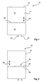
- Fig. 1 shows a first example of a hydrogen generator 10 for providing hydrogen from a suspension, comprising at least one housing 12, enclosing a generator volume 14, comprising a primary reaction volume 16 for providing a reaction mixture, and a collection volume 18 for capturing hydrogen emitting from the reaction volume.
- a first plurality of first inlets 20 is provided for injecting a first liquid with a first part of a reaction mixture into the reaction volume, wherein the first liquid is a suspension comprising silicone oil.
- the suspension comprises a carrier liquid and a hydrogen source material as the first part of a reaction mixture.
- a second plurality of second inlets 22 is provided for injecting a second liquid with a second part of the reaction mixture into the reaction volume, wherein the second liquid comprises water.
- the water is provided as carrier material together with a catalyst substance as the second part of the reaction mixture.
- the first and the second part of the reaction mixture are configured for reacting in a chemical reaction to generate hydrogen.
- a barrier 24 is provided between the reaction volume and the collection volume, which barrier is adaptable in its position to provide different ratio of reaction volume to collection volume. The adaptability is indicated with a double arrow 26. Further, the barrier 24 is permeable to gaseous hydrogen, which is indicated by showing the barrier 24 with a dashed line.
- the barrier 24 is further providing at least a barrier function to water steam.
- the hydrogen can pass the barrier, whereas the water steam is hindered or even completely blocked in passing the barrier 24.
- Fig. 2 shows a further example of the hydrogen generator 10, wherein the barrier layer 24 comprises a support structure 28 to stabilize a purification layer 30, which layer is permeable to hydrogen and impermeable to water steam.
- the support structure 28 is movably supported in relation to the volume for adaptively dividing the volume into the reaction volume 16 and the collection volume 18. Further, the purification layer 30 is consecutively renewable during operation.
- the purification layer is a silicone oil layer.
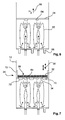
- Fig. 3 shows a further example of the hydrogen generator 10, wherein the support structure 28 is provided as a floating grid 32 to swim on a reaction mixture liquid level 34.
- the floating grid may be provided as a plastic grid with floating elements, for example silicone swimmers (see also Figs. 6 et seq.).
- Fig. 4 relates to the above-mentioned inlets 20, 22, which are provided as integrated inlets 34.
- the outlet openings of the integrated inlets 34 are arranged with a distance 36 to a bottom surface 38 of the housing 12.
- a first arrow 40 indicates the provision of a suspension for example, and a second arrow 42 indicates the provision of the carrier liquid for example, comprising water as carrier material, together with a catalyst substance.
- a coaxial arrangement is shown in Fig. 5 .
- An inner inlet 44 is provided for injecting the suspension.
- an outer inlet 46 enclosing the inner inlet 44 is provided for the injection of the carrier liquid comprising water.
- the outer inlet 46 has tapered side wall portions 48 near an opening 50, such that a jet of carrier liquid is pressed inwardly into a suspension jet ejected from an opening 52 of the inner inlets 44.
- the inner inlets 44 are providing the first inlets
- the outer inlet 46 provides the second inlets.
- a double bottom surface may provide a hollow space 54 through which a first volume stream V1 is provided.
- a second volume stream V2 is provided in the inner hollow space of the inner inlets.
- the volume stream V1 is larger than the volume stream V2.
- the water stream has a higher speed than the suspension stream.
- an inner diameter 56 of approximately 5 mm is provided, in combination with a distance 58 between the outer side of the inner inlets and the inner side of the outer inlets of approximately 1 mm.
- small droplets 60 are provided. This is in particular of importance, because it results, for example, in the metal-hydride to get into contact with water in a faster manner, in order to begin the hydrolytic reaction. Further, small droplets are easier to be destroyed by the formation of gas, and thus a more complete reaction is achievable. Further, small amounts of lighter oil can be separated from the suspension and reaction products. Of course, similar is the case for a reaction of sodium with water, the latter being the hydrogen source.
- Fig. 6 shows a swirling motion mixing the liquid, indicated with arrow 62, which also leads to an increased temperal stay of the droplets in the water, since these can be captured by the resulting stream a few times.
- the above-mentioned barrier 24 is shown, for example provided by silicone oil, lighter than water.
- water steam, as indicated with reference numeral 64 is hindered in passing the barrier layer 24, whereas hydrogen can pass the barrier 24, which hydrogen is indicated with arrow 66.
- Fig. 6 shows also a further feature, which however is not a necessary feature to be combined with the other features described above.
- Fig. 6 shows a number of drainage openings 68 for discharging waste liquid from the reaction volume.
- Fig. 7 shows the support structure 28 as the floating grid 32 to swim on the carrier liquid level 34.
- silicone swimmers 70 are provided for the swimming support.
- a double arrow 26 indicates the adaptability of the vertical position of the barrier 24.
- the support structure 28 is provided with lateral sealings 72 between the housing 12 and the floating grid 32.
- the sealings 72 are attached to the floating grid 32.
- the lateral sealings of the floating grid are also provided for closing off lateral openings arranged above, thus preventing that water steam and gas can reach the upper volume in an unfiltered way.
- the lateral sealings are provided with silicone as material.
- a material that is soaking silicone oil can also be provided, allowing better sealing properties and reduced friction forces.
- felt-like structures can also be provided for the lateral sealings.
- Fig. 8 shows a further example of the hydrogen generator 10 where a number of lateral drainage openings 74 is provided on a side wall 76 of the housing 12. Further, an overflow chamber 78 is provided and the at least one lateral drainage opening 74 opens into the overflow chamber 78.
- the lateral drainage openings 74 are provided with a vertical distance to each other in order to provide a balanced water level. For example, in an increased mass through put, the floating grid 32 is lifted and a further one of the lateral drainage openings 74 is exposed to the water level. Thus, a further amount of water can flow into the overflow chamber 78.
- Fig. 8 also shows a further aspect, which can be combined with one of the above-mentioned examples, or also with one of the further mentioned examples below. It must be noted that this further feature is shown as only an option in Fig. 8 .
- a rinse opening 80 near a lower base of a side wall with the at least one lateral drainage openings 74 is provided.
- the rinse opening 80 is configured for emitting a water jet for cleaning the at least one lateral drainage opening 74.
- An arrow 82 indicates the provision of wall rinsing liquid.
- a still further feature is shown as an option in Fig. 8 , namely a flexible drawn-off conduit 84 for drawing off silicone oil from the barrier 24.
- the conduit can be provided as a flexible silicone drainage pipe that can prevent an increase of the barrier film in a too large amount.
- FIG. 9 A further feature is shown in Fig. 9 in form of a supply opening 86 for providing fresh or light silicone oil to the interior walls of the overflow chamber 78.
- the provided silicone oil can be cooled.
- the lateral drainage openings can also be used for leading away or drawing off gaseous bubbles, for example water steam, or water steam with hydrogen.
- the support structure 28 is provided with guiding means (not further shown in detail) for guiding gaseous bubbles generated in the reaction mixture liquid towards at least one side edge of the support structure.
- the guiding means may comprise inclined surfaces and/or inclined roofs.
- the support structure 28 is provided with a plurality of cooling elements (not further shown).
- the cooling elements may be provided as small cooling pipes, for example integrated in the grid structure of the floating grid 32.
- the overflow chamber 78 discharges into an after-reaction chamber 88 for a secondary generation of hydrogen, indicated with a secondary arrow 90.
- the after-reaction chamber 88 is indicated with a side wall 92, a secondary discharge opening 94 for water, a secondary discharge opening 96 for the drainage of waist products collected at the bottom of the chamber.
- the after-reaction chamber 88 may also be provided with a floating grid structure 98.
- the so-to-speak waterfall, as indicated with reference numeral 100 may also provide a rinsing procedure for the gaseous medium and a mixing injection of the falling liquid into the after-reaction chamber 88.
- a heat exchanger 102 is provided inside the collection volume 18 for withdrawing heat energy from the inside of the collection volume. This is indicated in Fig. 10 , but must be understood as an option only.
- the water to be injected into the reaction volume 16 may be conducted such to pass the heat exchanger 102, thus drawing off thermal energy from the volume comprising the generated hydrogen. This supports the approach to reduce the amount of water steam in the collection volume 18 to a minimum.
- the reaction volume comprises the first liquid and the second liquid providing a reaction mixture 104 of the first and the second parts, as shown in Fig. 4 et seq.
- the reaction mixture comprises a mixture of the suspension and the carrier liquid.
- the suspension may be provided as silicone oil
- the hydrogen source material may be provided as metal-hydride material.
- the silicone oil comprises a first silicone oil part with a density smaller than the density of water, and a second silicone oil part with a density larger than the density of water.
- the suspension is a pulp suspension of sodium borohydride, NaBH 4 .
- the first liquid comprises the silicone oil as a first carrier liquid and a reaction substance as the first part of the reaction mixture
- the second liquid comprises water as a hydrogen source material as the second part of the reaction mixture.
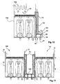
- Fig. 11 indicates a further example of the hydrogen generator 10, comprising a plurality 106 of housings 12, each enclosing a generator volume 14 with a primary reaction volume 16 and a collection volume 18.
- the at least two housings 12 are each provided with an overflow chamber 78 discharging in a common after-reaction chamber 108 for the secondary generation of hydrogen.
- Fig. 11 shows the housings 12 to be provided with the overflow chamber 78, the lateral drainage openings 74 only on one side
- Fig. 12 shows an example with a housing 12 having an overflow chamber 78 on at least two sides, for example on opposite sides.
- a number of different arrangements of the hydrogen generator having the plurality 106 of housings 12 is shown in schematic top views.
- the housings 12 may be provided with a rectangular or square form and displaced such that in a row of housings, the common after-reaction chamber 108 is provided in-between two adjacent housings 12.
- Fig. 13B shows an example of a number of housings 12 arranged in rows and columns and a grid-like common after-reaction chamber 108 comprising different portions that can be connected to each other, as shown, or can be separated into separate chambers (not further shown).
- FIG. 13C shows an example of housings 12 having a rectangular form, where the common after-reaction chambers are provided along the longitudinal sides, thus ensuring that sufficient lateral drainage openings can be provided.
- a further number of rectangular housings 12 is provided, attached to the adjacent housing 12 on the end faces.
- Fig. 13D shows housings 12 with a hexagonal shape and a resulting grid-like structure for the common after-reaction chambers 108.
- Fig. 13E shows a plurality of circular housings 12 and resulting rest spaces 110 providing space for the after-reaction chambers 108.
- Fig. 13E shows a rectangular displacement of the circular housings 12, whereas Fig.
- FIG. 13F shows a more compact arrangement of the circular housings resulting in smaller rest spaces in-between for the after-reaction chambers 88.
- Providing circular housings comprises the advantage that a minimum of wall surface has to be provided for enclosing a maximum volume size, and also edges of a sealing between a floating grid and the side walls are avoided. By letting the circular housings touch each other, a further stability is provided. Of course, it is also possible to provide circular housings 12 displaced from the adjacent housing such that a continuous rest space is provided for the after-reaction chamber.
- a stationary arrangement e.g. a power plant.
- the plant is provided with hydrogen operated systems or apparatus, and a hydrogen source.
- the hydrogen source is a system for generating hydrogen according to the above-mentioned examples.
- the hydrogen source generates hydrogen for driving the hydrogen operated systems or apparatus and supplies the hydrogen to the latter, for example for providing electric energy for example, a number of hydrogen sources can be assembled and connected to provided a hydrogen generator with an enlarged scalability, for example for driving one or several gas turbines.
- Fig. 14 shows a schematic setup of a system 200 for generating hydrogen, comprising a first storage device 210 for storing a first liquid with a first part of a reaction mixture, wherein the first liquid is a suspension comprising silicone oil. Further, a second storage device 212 for storing a second liquid with a second part of the reaction mixture is provided, wherein the second liquid comprises water. The first and the second part of the reaction mixture are configured to react in a chemical reaction to generate hydrogen. For example, the water is provided as carrier material together with a catalyst substance as a second part of the reaction mixture. Further, a hydrogen generator 214 in accordance with one of the above described examples for the hydrogen generator 10 is provided.
- Schematic connection lines 216, 218 indicate the connection of the storage devices 210, 212 with the hydrogen generator 214. It must be noted that the separate connecting lines are shown schematically only and do not mean an injection of the respective liquid or material separated from each other. Further, a hydrogen extraction point 220 is provided.
- the first storage device 210 provides the first liquid, for example comprising the hydrogen source material, to the first inlets (not further shown), and the second storage device 212 provides the second liquid, for example water with a catalyst substance, to the second inlets (also not further shown).
- the first storage device 210 provides a reaction material to the first inlets and the second storage device 212 provides water as a hydrogen source to the second inlets.
- a number of housings is provided and connected to the storage devices 210, 212 (not further shown in detail).
- Fig. 15 shows a vehicle 300 which is at least partly operated by hydrogen, comprising hydrogen operated driving means 310 and a hydrogen source 312.
- a system for generating hydrogen according to the above-mentioned example, indicated with reference numeral 200, is provided.
- a first storage device 210 and a second storage device 212 are provided in connection with a hydrogen generator 10 providing hydrogen via a supply line 314 to the hydrogen operated driving means 310.
- a common box 316 enclosing the above mentioned features indicates the provision of the hydrogen generation inside a vehicle, which vehicle and its respective capability for mobility, is indicated with a vehicle arrow 318.
- the mobility may be provided in form of a driving movement over ground, and/or for uplift and propulsion.
- the vehicle is an aircraft, such as an airplane, or a helicopter. In another example, the vehicle is a boat. In a still further example, the vehicle is an automotive, such as a car, a coach, or a truck. In a further example, also not further shown, the vehicle is a train, or other track-guided vehicle such as a tram or subway.
- Fig. 16 shows a method 400 for generating hydrogen, comprising the following steps:
- a first liquid with a first part of a reaction mixture is supplied in a first sub step 412 into a reaction volume.
- the first liquid is a suspension comprising silicone oil.
- the silicone oil comprises a first silicone oil part with a density smaller than the density of water, and a second silicone oil part with a density larger than the density of water.
- a second liquid with a second part of the reaction mixture is supplied into the reaction volume.
- the second liquid comprises water.
- the first and the second part of the reaction mixture are provided for reacting in a chemical reaction in which hydrogen is generated.
- a silicone layer is provided on the top of the reaction mixture level by the first silicone oil, which silicone layer provides a barrier for water steam and which silicone layer is permeable for hydrogen.
- the reaction mixture takes place, generating gaseous hydrogen.
- the hydrogen is passing through the barrier. Further, in a fifth step 422, the hydrogen is provided for further purposes.
- the first sub step 412 is also referred to as step a1), the second sub step 414 as step a2), the second step 416 as step b), the third step 418 as step c), the fourth step 420 as step d), and the fifth step 422 as step e).
- the first liquid supplied in the first sub step 412 comprises the silicone oil as a first carrier liquid and a hydrogen source material as the first part of the reaction mixture.
- the second liquid supplied in the second sub step 414 comprises water as a second carrier liquid and a catalyst substance as the second part of the reaction mixture.
- the first liquid supplied in the first sub step 412 comprises the silicone oil as a first carrier liquid and a reaction substance as the first part of the reaction mixture.
- the second liquid supplied in the second sub step 414 comprises water as a hydrogen source material as the second part of the reaction mixture.
- the reaction may be conducted as pyrolytic reaction and/or hydrolytic reaction under high pressures and high temperatures (see above).
- a mixing procedure is provided in which mass streams can be varied over a larger range.
- large amounts of hydrogen can be provided with the same time of reactor with only a minimum amount of adaption.
- a reactor with an increased range of use is provided.
- a floating grid for example, for supporting the silicone oil layer
- the feeding or supply of the reaction parts can be provided such that a good mixture inside the volume is provided, thus leading to a rather rough liquid level or surface.
- the supporting structure ensures that the oil film is not broken apart.
- cooling elements inside the grid the generation of water steam can be reduced to a minimum.
Landscapes
- Chemical & Material Sciences (AREA)
- Organic Chemistry (AREA)
- Chemical Kinetics & Catalysis (AREA)
- Engineering & Computer Science (AREA)
- Combustion & Propulsion (AREA)
- Life Sciences & Earth Sciences (AREA)
- Inorganic Chemistry (AREA)
- Manufacturing & Machinery (AREA)
- Sustainable Development (AREA)
- Sustainable Energy (AREA)
- Electrochemistry (AREA)
- General Chemical & Material Sciences (AREA)
- Health & Medical Sciences (AREA)
- General Health & Medical Sciences (AREA)
- Fuel Cell (AREA)
- Feeding, Discharge, Calcimining, Fusing, And Gas-Generation Devices (AREA)
Abstract
Description
- The present invention relates to the generation of hydrogen, and relates in particular to a hydrogen generator for providing hydrogen from a suspension, to a system for generating hydrogen, to a vehicle at least partly operated by hydrogen, and to a method for generating hydrogen, as well as to a use of a hydrogen generator in a vehicle, and to a use of a system for generating hydrogen in a vehicle.
- For the generation of hydrogen, reactors are used for providing hydrogen, for example in remote environments, or also for use onboard a vehicle. As an example, metal-hydrides are mixed with water, providing a reaction mixture inside a tank. Hydrogen can then be collected or captured and separated for further use. Another example among further examples is the provision of pulverised pure Sodium (Na) in liquid silicone oil. For providing the mixture of metal-hydrides and water, mechanical mixing apparatuses are known. Further, acoustic mixing devices are known. For example,
DE 10 2005 039 061 A1 describes a method for generating hydrogen from a complex metal-hydride. However, it has been shown that predetermined volumes are often required for an efficient operation, thus allowing a production of hydrogen only in a small spectrum, relating to the amount that can be produced. - There may be a need to provide a hydrogen generator with an increased an improved bandwidth of use, i.e. a hydrogen generator with an optimized usability range.
- The object of the present invention is solved by the subject-matter of the independent claims, wherein further embodiments are incorporated in the dependent claims.
- It should be noted that the following described aspects of the invention apply also for the hydrogen generator for providing hydrogen from a suspension, the system for generating hydrogen, the vehicle at least partly operated by hydrogen, and the method for generating hydrogen, as well as to the use of a hydrogen generator in a vehicle, and the use of a system for generating hydrogen in a vehicle.
- According to a first aspect of the present invention, a hydrogen generator for providing hydrogen from a suspension is provided, comprising at least one housing enclosing a generator volume comprising a primary reaction volume for providing a reaction mixture. The at least one housing is enclosing also a collection volume for capturing hydrogen emitting from the reaction volume. Further, a first plurality of first inlets and a second plurality of second inlets is provided. The first inlets are provided for injecting a first liquid with a first part of a reaction mixture into the reaction volume. The first liquid is a suspension comprising silicone oil. The second inlets are provided for injecting a second liquid with a second part of the reaction mixture into the reaction volume. The second liquid comprises water. The first and the second part of the reaction mixture are configured for reacting in a chemical reaction to generate hydrogen. A barrier is provided between the reaction volume and the collection volume, which barrier is adaptable in its position to provide different ratio of reaction volume to collection volume. The barrier is permeable to gaseous hydrogen, and the barrier provides at least a barrier function to water steam.
- In one example, the first liquid comprises the silicone oil as a first carrier liquid and a hydrogen source material as the first part of the reaction mixture. The second liquid comprises water as a second carrier liquid and a catalyst substance as the second part of the reaction mixture.
- In another example, the first liquid comprises the silicone oil as a first carrier liquid and a reaction substance as the first part of the reaction mixture. The second liquid comprises water as a hydrogen source material as the second part of the reaction mixture.
- The term "barrier" relates to providing a separating or selecting function for water steam. The hydrogen can pass the barrier, whereas the water steam is hindered or even completely blocked in passing the barrier. The barrier provides a cleaning or rinsing of the drawn-off gaseous reaction product, or discharged gaseous reaction product. The cleaning or rinsing is provided by the passing through of only hydrogen, and stopping or at least hindering water steam to penetrate. Also, particulate material, such as suspended solids, e.g. salts, are filtered by the barrier layer, for example, when these are suspended in water steam. By the barrier, the reaction volume is adaptable in size, i.e. a scalable volume is provided. The barrier may comprise a membrane layer permeable to hydrogen and impermeable to water steam. In another example, the barrier layer comprises a silicone oil layer, which silicone oil layer is permeable to hydrogen and impermeable to water steam.
- According to an exemplary embodiment, the barrier layer comprises a support structure to stabilize a purification layer, which layer is permeable to hydrogen and impermeable to water steam. The support structure is movably supported in relation to the volume for adaptively dividing the volume into the reaction volume and the collection volume. The purification layer is consecutively renewable during operation.
- According to an exemplary embodiment, the purification layer is a silicone oil layer. The purification layer may also comprise a mineral oil product, organic and inorganic oils, or glycerines, in addition or as an alternative to silicone oil.
- The first inlets are configured such that the suspension is injected into the carrier liquid. For example, the suspension is injected into the carrier liquid in small droplets, for example approximately 1 mm in size.
- In one example, the inlets are attached to the support structure. The inlets are oriented downwards, such that the injection of the carrier liquid and the injection of the suspension are provided from an upper area of the generator.
- In another example, the outlet openings of the first inlets are provided on an inner bottom surface of the housing, and the outlet openings are provided spaced apart from the bottom surface.
- In a further example, at least a part of the first inlets may be arranged coaxially with one of the second inlets. The outlet openings of the second inlets are provided with tapered side walls, such that a jet of carrier material is pressed inwardly into a suspension jet, ejected from the first inlets.
- In one example, the support structure is suspend from above or supported from below by activation means in dependency from the level of the current reaction liquid level.
- According to an exemplary embodiment, the support structure is provided as a floating grid to swim on a reaction mixture liquid level.
- The floating grid may be provided as a plastic grid with floating elements, e.g. silicone swimmers. The floating grid may be provided with a flexible grid with a flexible plane, or bendable plane.
- According to an exemplary embodiment, the support structure is provided with guiding means for guiding gaseous bubbles generated in the reaction mixture liquid towards at least one side edge of the support structure. The guiding means comprise inclined surfaces" and/or inclined grooves.
- For example, the side edges are the boundaries of the support structure. The floating grid may be swimming on top of the carrier material.
- According to an exemplary embodiment, the support structure is provided with a plurality of cooling elements.
- The cooling elements may be provided as small or micro cooling pipes, or as thermal transfer elements, which are connectable to a source of cooling energy, for example, active cooling elements connected to a heat exchanger.
- At least one lateral sealing may be provided between the housing and the floating grid.
- It must be noted that according to a further example, a silicone oil layer, or other material layer, is provided as a barrier between the primary reaction volume and the collection volume, where the barrier is fixed in its position, for example by means of a fixed or stabilized support structure. It must be noted further, that such an example can also be combined with the other described examples in the forgoing and in the following.
- According to an exemplary embodiment, at least one lateral drainage opening is provided on a side wall of the housing. An overflow chamber is provided, wherein the at least one lateral drainage opening opens into the overflow chamber. The overflow chamber discharges into an after-reaction chamber for a secondary generation of hydrogen. The after-reaction chamber is also referred to as secondary reaction volume.
- For example, a plurality of lateral drainage openings is provided with a vertical distance to each other, in order to provide a balanced water level. For example, in an increased mass throughput, or mass flow rate, the water level raises, lifting the floating grid and additional openings of the plurality or openings are exposed to the water level. The at least one lateral drainage opening may be provided as a drainage groove.
- Further, at least one drainage or discharge outlet is provided on the bottom surface.
- According to an exemplary embodiment, at least one drainage opening is provided for discharging raised liquid from the reaction volume. In addition, or alternatively, at least one outlet opening for discharging hydrogen from the collection volume is provided. Still further, also additionally or alternatively, at least one rinse opening near a lower base of a side wall with at least one lateral drainage opening is provided, wherein the rinse opening is configured or emitting a water jet for cleaning the at least one lateral drainage opening. Thus, the inner side walls are protected against encrusting due to the rinsing function.
- According to an exemplary embodiment, a heat exchanger is provided inside the generator volume, for example inside the collection volume, for withdrawing heat energy from the inside of the collection volume.
- According to an exemplary embodiment, the reaction volume comprises the first liquid and the second liquid providing the reaction mixture of the first and the second parts. The silicone oil comprises a first silicone oil part with a density smaller than the density of water, and a second silicone oil part with a density larger than the density of water. It is further provided:
- I) that the first liquid comprises the silicone oil as a first carrier liquid and a hydrogen source material as the first part of the reaction mixture; and
the second liquid comprises water as a second carrier liquid and a catalyst substance as the second part of the reaction mixture; or - II) that the first liquid comprises the silicone oil as a first carrier liquid and a reaction substance as the first part of the reaction mixture; and
the second liquid comprises water as a hydrogen source material as the second part of the reaction mixture. - For example, the suspension is a pulp suspension of sodium borohydride (NaBH4). For example, the first silicone oil part has a density of smaller than approximately 0.95 kg/l, and the second silicone oil part has a density of larger than approximately 1.05 kg/l. The ratio or fraction of the first silicone oil part may be smaller than the ratio or fraction of the second silicone oil part. For example, the first silicone oil part is provided in a volume amount of approximately 5 % to 30 %, for example approximately 10 %, and the second silicone oil part is provided in a volume amount of approximately 95 % to 70 %, for example approximately 90 %.
- As the barrier, an oil film is provided on the upper side of the carrier material. For example, the oil film is provided by the first silicone oil part.
- According to an exemplary embodiment, a plurality of housings is provided, each enclosing a generator volume. Further, at least two housings are each provided with an overflow chamber discharging in a common after-reaction chamber for the secondary generation of hydrogen.
- The housings may be provided with a rectangular form in a plan view, or with hexagonal form, or circular form, and displaced to each other such that the after reaction chambers are provided in-between. The housings may be provided with a round shape in a plan view, and the resulting rest spaces are used for the after-reaction chamber. The housings may thus be provided contacting each other at certain instances, or completely displaced to each other. For example, a two-dimensional grid with rows and columns is provided for the housings. In another example, the housings are provided with a rectangular form, and are attached to each other on their end faces. The common after-reaction chambers are provided at least along the longitudinal sides.
- According to a second aspect, a system for generating hydrogen is provided, comprising a first storage device and a second storage device. The first storage device is provided for storing a first liquid with a first part of a reaction mixture; wherein the first liquid is a suspension comprising silicone oil. The second storage device is provided for storing a second liquid with a second part of the reaction mixture, wherein the second liquid comprises water. The first and the second part of the reaction mixture are configured to react in a chemical reaction to generate hydrogen. Further, a hydrogen extraction point is provided. Still further, a hydrogen generator according to one of the above-mentioned examples is provided. The first storage device provides the first liquid to the first inlets, and the second storage device provides the second liquid to the second inlets.
- The first liquid may comprise a hydrogen source material such as metal-hydrides and the second liquid may comprise water as a carrier material with a catalyst substance.
- For example, a hydrogen storage device is provided, which is connected to a hydrogen extraction point. Further, it is also possible to connect a consumer device, for example a hydrogen operated driving means, to the hydrogen extraction point or the hydrogen storage device.
- According to a third aspect, a vehicle at least partly operated by hydrogen is provided, comprising hydrogen operated driving means, and a hydrogen source. As the hydrogen source, a system for generating hydrogen according the above-mentioned examples is provided. Further, the hydrogen source provides hydrogen for driving the hydrogen operated driving means. The driving source may be a fuel cell or a combustion engine, for example.
- For example, the hydrogen can be provided so-to-speak on demand. Thus, storage means can be reduced to a minimum or even avoided completely. A buffer device can be provided for balancing small differences between production capacity, which is adaptable due to the adaptable barrier, and the hydrogen consumption.
- The vehicle may be an aircraft, such as an airplane or a helicopter. The vehicle may also be a boat. The vehicle may still further be an automotive, such as a car, a coach, or a truck. The vehicle may also be provided as a train.
- In another example, a stationary arrangement, for example a power plant, is provided that is at least partly operated by hydrogen, comprising hydrogen operated systems or apparatus, and a hydrogen source. As the hydrogen source, a system for generating hydrogen according the above-mentioned examples is provided. Further, the hydrogen source provides hydrogen for driving the hydrogen operated systems or apparatus, for example for providing electric energy. Thus, it is possible to provide hydrogen in dependency from an actual demand. For example, storage means can be reduced to a minimum or can be avoided even completely. For balancing smaller purposes to align differences in production capacity and hydrogen consumption, a buffer device can be provided. For stationary operation of a power plant with hydrogen, for example, up to approximately 40 m3/s may be required at normal pressure, or approximately 450 g/s up to approximately 3500 g/s. By providing a scalable setup of reactors according to the present invention, such large amounts can be provided and supplied in stationary power plants.
- According to a fourth aspect, a method for generating hydrogen is provided, comprising the following steps:
- a1) Supplying a first liquid with a first part of a reaction mixture into a reaction volume; wherein the first liquid is a suspension comprising silicone oil. The silicone oil comprises a first silicone oil part with a density smaller than the density of water, and a second silicone oil part with a density larger than the density of water.
- a2) Supplying a second liquid with a second part of the reaction mixture into the reaction volume; wherein the second liquid comprises water. The first and the second part of the reaction mixture are provided for reacting in a chemical reaction in which hydrogen is generated.
- b) Providing a silicone layer on the top of the reaction mixture level by the first silicone oil. The silicone layer provides a barrier for water steam and silicone layer is permeable for hydrogen.
- c) Reacting of the reaction mixture, generating gaseous hydrogen.
- d) Passing of the hydrogen through the barrier.
- e) Providing the hydrogen for further purposes.
- The suspension of the first liquid may comprise the silicone oil as a carrier liquid and a hydrogen source material, for example a metal-hydride material. The water of the second liquid may be provided as a carrier material, or carrier liquid, together with a catalyst substance.
- The reaction may be conducted as pyrolytic reaction and/or hydrolytic under high pressures and high temperatures. For example, the term "high pressure" relates to a pressure of approximately minimum 20 bar inside the reaction chamber. Further, high temperatures are provided for the above-mentioned reaction. For example, the term "high pressure" relates to a temperature of approximately 200 °C inside the reaction chamber.
- According to a fifth aspect, a use of a hydrogen generator according to one of the above-mentioned examples in a vehicle is provided. According to a still further aspect, a use of a system for generating hydrogen according to one of the above-mentioned examples, in a vehicle is provided.
- The vehicle may be an aircraft, a ship, a train, or an automotive, to name only a few examples.
- According to an aspect of the present invention, the generator volume is divided into two different sections, namely a first part for receiving the reaction mixture, i.e. the liquid in which the reaction takes place, and a second part for receiving the thus produced hydrogen gas. The separation is achieved with a separation layer that is capable of being passed by the hydrogen, and which blocks off or at least hinders the passing of water steam and other substances to at least a great extent, thus providing a cleaning function. By provided one of the substances for the reaction mixture, to comprise a silicone oil that is lighter than the water provided for the reaction, the barrier layer is so-to-speak already present in the basic components for the reaction. Thus, the silicone oil provided to the reaction chamber during the process of production leads to a swimming barrier, which is then capable of following different levels of the reaction mixture, for example when achieving larger or smaller throughputs, i.e. smaller or larger amounts of hydrogen to be produced. A further advantage of the so-to-speak imminent silicone oil barrier layer is the capability of constantly replacing and thus refreshing the barrier. For example, when the reaction takes place and the reaction products contact the barrier layer and the hydrogen passes the barrier layer, at the same time so-to-speak collecting or filtering off further unwanted substances takes place. Thus, the silicon, which is itself lighter than the water, is becoming increasingly heavy, up to an extent where the thus soaked or contaminated silicone is heavier than water and begins to sink to the bottom of the reaction volume. At the bottom, the used silicone oil can be discharged or drained off.
- These and other aspects of the present invention will become apparent from and be elucidated with reference to the embodiments described hereinafter.
- Exemplary embodiments of the invention will be described in the following with reference to the following drawings:
- Fig. 1
- shows an example for a hydrogen generator for providing hydrogen from a suspension in a schematic cross section;
- Fig. 2
- shows a further example of a hydrogen generator;
- Fig. 3
- shows a still further example of a hydrogen generator;
- Fig. 4
- shows an example of inlets of a hydrogen generator;
- Fig. 5
- shows a further example of inlets in a cross-section;
- Fig. 6
- shows a further example of a hydrogen generator in a cross-section;
- Figs. 7 to 9
- show further examples of hydrogen generators in a cross-section;
- Fig. 10
- shows a further example of a hydrogen generator;
- Fig. 11
- shows a further example of a hydrogen generator with two housings and a common chamber in-between;
- Fig. 12
- shows a still further example of a hydrogen generator with two adjacent after-reaction chambers for secondary generation of hydrogen;
- Fig. 13
- shows six examples of hydrogen generators with a number of housings in a top or plan view in a schematic illustration in
Figs. 13A to 13F ; - Fig. 14
- shows an example of a system for generating hydrogen in a schematic setup;
- Fig. 15
- shows an example of a vehicle at least partly operated by hydrogen in a schematic functional diagram; and
- Fig. 16
- shows basic steps of a method for generating hydrogen according to an exemplary embodiment.
- As an example for hydrogen generation, metal-hydride suspensions are used. For example, NaBH4 pulp suspensions are mixed with water for hydrogen production. For the preparation of NaBH4 Pulp suspension, granules of NaBH4 are added with a liquid, comprising water and metal salts free liquid medium, thus leading to NaBH4 pulp suspension which can be stored and transported in hermetic containers and tanks. For the hydrogen production, the NaBH4 pulp suspension can be mixed with water, resulting in gaseous hydrogen, and of course waste to be handled in further treatments steps or storage and transportation steps. The hydrogen can be used, for example, to operate proton exchange membrane fuel cells or gas turbines, just to mention a few examples.
-
Fig. 1 shows a first example of ahydrogen generator 10 for providing hydrogen from a suspension, comprising at least onehousing 12, enclosing agenerator volume 14, comprising aprimary reaction volume 16 for providing a reaction mixture, and acollection volume 18 for capturing hydrogen emitting from the reaction volume. Further, a first plurality offirst inlets 20 is provided for injecting a first liquid with a first part of a reaction mixture into the reaction volume, wherein the first liquid is a suspension comprising silicone oil. For example, the suspension comprises a carrier liquid and a hydrogen source material as the first part of a reaction mixture. Still further, a second plurality ofsecond inlets 22 is provided for injecting a second liquid with a second part of the reaction mixture into the reaction volume, wherein the second liquid comprises water. For example, the water is provided as carrier material together with a catalyst substance as the second part of the reaction mixture. The first and the second part of the reaction mixture are configured for reacting in a chemical reaction to generate hydrogen. Abarrier 24 is provided between the reaction volume and the collection volume, which barrier is adaptable in its position to provide different ratio of reaction volume to collection volume. The adaptability is indicated with adouble arrow 26. Further, thebarrier 24 is permeable to gaseous hydrogen, which is indicated by showing thebarrier 24 with a dashed line. Thebarrier 24 is further providing at least a barrier function to water steam. Thus, the hydrogen can pass the barrier, whereas the water steam is hindered or even completely blocked in passing thebarrier 24. -
Fig. 2 shows a further example of thehydrogen generator 10, wherein thebarrier layer 24 comprises asupport structure 28 to stabilize apurification layer 30, which layer is permeable to hydrogen and impermeable to water steam. Thesupport structure 28 is movably supported in relation to the volume for adaptively dividing the volume into thereaction volume 16 and thecollection volume 18. Further, thepurification layer 30 is consecutively renewable during operation. - For example, the purification layer is a silicone oil layer.
-
Fig. 3 shows a further example of thehydrogen generator 10, wherein thesupport structure 28 is provided as a floatinggrid 32 to swim on a reactionmixture liquid level 34. For example, the floating grid may be provided as a plastic grid with floating elements, for example silicone swimmers (see alsoFigs. 6 et seq.). -
Fig. 4 relates to the above-mentionedinlets integrated inlets 34. The outlet openings of theintegrated inlets 34 are arranged with adistance 36 to abottom surface 38 of thehousing 12. Afirst arrow 40 indicates the provision of a suspension for example, and asecond arrow 42 indicates the provision of the carrier liquid for example, comprising water as carrier material, together with a catalyst substance. - In order to provide an efficient mixture and generation of small as possible silicone droplets, a coaxial arrangement is shown in
Fig. 5 . Aninner inlet 44 is provided for injecting the suspension. Further, anouter inlet 46, enclosing theinner inlet 44 is provided for the injection of the carrier liquid comprising water. Theouter inlet 46 has taperedside wall portions 48 near anopening 50, such that a jet of carrier liquid is pressed inwardly into a suspension jet ejected from anopening 52 of theinner inlets 44. Thus, theinner inlets 44 are providing the first inlets, and theouter inlet 46 provides the second inlets. For feeding of theouter inlets 46, a double bottom surface may provide a hollow space 54 through which a first volume stream V1 is provided. A second volume stream V2 is provided in the inner hollow space of the inner inlets. For example, the volume stream V1 is larger than the volume stream V2. Thus, the water stream has a higher speed than the suspension stream. - As an example only, an
inner diameter 56 of approximately 5 mm is provided, in combination with adistance 58 between the outer side of the inner inlets and the inner side of the outer inlets of approximately 1 mm. - Thus,
small droplets 60 are provided. This is in particular of importance, because it results, for example, in the metal-hydride to get into contact with water in a faster manner, in order to begin the hydrolytic reaction. Further, small droplets are easier to be destroyed by the formation of gas, and thus a more complete reaction is achievable. Further, small amounts of lighter oil can be separated from the suspension and reaction products. Of course, similar is the case for a reaction of sodium with water, the latter being the hydrogen source. - As shown in
Fig. 6 , by providing the feed of the suspensions with the distance 36 (seeFig. 5 ) from the bottom layer, and in particular supported by the release of thermal energy, a swirling motion mixing the liquid is induced, indicated witharrow 62, which also leads to an increased temperal stay of the droplets in the water, since these can be captured by the resulting stream a few times. InFig. 6 , the above-mentionedbarrier 24 is shown, for example provided by silicone oil, lighter than water. Thus, water steam, as indicated withreference numeral 64 is hindered in passing thebarrier layer 24, whereas hydrogen can pass thebarrier 24, which hydrogen is indicated witharrow 66.Fig. 6 shows also a further feature, which however is not a necessary feature to be combined with the other features described above.Fig. 6 shows a number ofdrainage openings 68 for discharging waste liquid from the reaction volume. -
Fig. 7 shows thesupport structure 28 as the floatinggrid 32 to swim on thecarrier liquid level 34. For the swimming support,silicone swimmers 70 are provided. Adouble arrow 26 indicates the adaptability of the vertical position of thebarrier 24. - The
support structure 28 is provided withlateral sealings 72 between thehousing 12 and the floatinggrid 32. For example, thesealings 72 are attached to the floatinggrid 32. The lateral sealings of the floating grid are also provided for closing off lateral openings arranged above, thus preventing that water steam and gas can reach the upper volume in an unfiltered way. For example, the lateral sealings are provided with silicone as material. However, a material that is soaking silicone oil can also be provided, allowing better sealing properties and reduced friction forces. Further, felt-like structures can also be provided for the lateral sealings. -
Fig. 8 shows a further example of thehydrogen generator 10 where a number oflateral drainage openings 74 is provided on aside wall 76 of thehousing 12. Further, anoverflow chamber 78 is provided and the at least onelateral drainage opening 74 opens into theoverflow chamber 78. - As can be seen, the
lateral drainage openings 74 are provided with a vertical distance to each other in order to provide a balanced water level. For example, in an increased mass through put, the floatinggrid 32 is lifted and a further one of thelateral drainage openings 74 is exposed to the water level. Thus, a further amount of water can flow into theoverflow chamber 78. -
Fig. 8 also shows a further aspect, which can be combined with one of the above-mentioned examples, or also with one of the further mentioned examples below. It must be noted that this further feature is shown as only an option inFig. 8 . A rinseopening 80 near a lower base of a side wall with the at least onelateral drainage openings 74 is provided. The rinseopening 80 is configured for emitting a water jet for cleaning the at least onelateral drainage opening 74. Anarrow 82 indicates the provision of wall rinsing liquid. - A still further feature is shown as an option in
Fig. 8 , namely a flexible drawn-offconduit 84 for drawing off silicone oil from thebarrier 24. The conduit can be provided as a flexible silicone drainage pipe that can prevent an increase of the barrier film in a too large amount. - A further feature is shown in
Fig. 9 in form of asupply opening 86 for providing fresh or light silicone oil to the interior walls of theoverflow chamber 78. For example, the provided silicone oil can be cooled. - The lateral drainage openings can also be used for leading away or drawing off gaseous bubbles, for example water steam, or water steam with hydrogen.
- In order to support the transport or travel of the steam bubbles 64, the
support structure 28 is provided with guiding means (not further shown in detail) for guiding gaseous bubbles generated in the reaction mixture liquid towards at least one side edge of the support structure. The guiding means may comprise inclined surfaces and/or inclined roofs. - According to a further example, the
support structure 28 is provided with a plurality of cooling elements (not further shown). For example, the cooling elements may be provided as small cooling pipes, for example integrated in the grid structure of the floatinggrid 32. - In
Fig. 10 , theoverflow chamber 78 discharges into an after-reaction chamber 88 for a secondary generation of hydrogen, indicated with asecondary arrow 90. Thus, in addition to the primary generation, indicated with anarrow 92, an efficient use of the reaction process is provided. The after-reaction chamber 88 is indicated with aside wall 92, asecondary discharge opening 94 for water, asecondary discharge opening 96 for the drainage of waist products collected at the bottom of the chamber. The after-reaction chamber 88 may also be provided with a floatinggrid structure 98. The so-to-speak waterfall, as indicated withreference numeral 100 may also provide a rinsing procedure for the gaseous medium and a mixing injection of the falling liquid into the after-reaction chamber 88. - According to a further example, a
heat exchanger 102 is provided inside thecollection volume 18 for withdrawing heat energy from the inside of the collection volume. This is indicated inFig. 10 , but must be understood as an option only. For example, the water to be injected into thereaction volume 16 may be conducted such to pass theheat exchanger 102, thus drawing off thermal energy from the volume comprising the generated hydrogen. This supports the approach to reduce the amount of water steam in thecollection volume 18 to a minimum. - According to a further example, the reaction volume comprises the first liquid and the second liquid providing a
reaction mixture 104 of the first and the second parts, as shown inFig. 4 et seq. For example, the reaction mixture comprises a mixture of the suspension and the carrier liquid. The suspension may be provided as silicone oil, and the hydrogen source material may be provided as metal-hydride material. As mentioned above, the silicone oil comprises a first silicone oil part with a density smaller than the density of water, and a second silicone oil part with a density larger than the density of water. For example, the suspension is a pulp suspension of sodium borohydride, NaBH4. In another example, the first liquid comprises the silicone oil as a first carrier liquid and a reaction substance as the first part of the reaction mixture, and the second liquid comprises water as a hydrogen source material as the second part of the reaction mixture. -
Fig. 11 indicates a further example of thehydrogen generator 10, comprising aplurality 106 ofhousings 12, each enclosing agenerator volume 14 with aprimary reaction volume 16 and acollection volume 18. The at least twohousings 12 are each provided with anoverflow chamber 78 discharging in a common after-reaction chamber 108 for the secondary generation of hydrogen. -
Fig. 11 shows thehousings 12 to be provided with theoverflow chamber 78, thelateral drainage openings 74 only on one side, whereasFig. 12 shows an example with ahousing 12 having anoverflow chamber 78 on at least two sides, for example on opposite sides. - In
Fig. 13A to 13F , a number of different arrangements of the hydrogen generator having theplurality 106 ofhousings 12 is shown in schematic top views. According to the example inFig. 13A , thehousings 12 may be provided with a rectangular or square form and displaced such that in a row of housings, the common after-reaction chamber 108 is provided in-between twoadjacent housings 12.Fig. 13B shows an example of a number ofhousings 12 arranged in rows and columns and a grid-like common after-reaction chamber 108 comprising different portions that can be connected to each other, as shown, or can be separated into separate chambers (not further shown).Fig. 13C shows an example ofhousings 12 having a rectangular form, where the common after-reaction chambers are provided along the longitudinal sides, thus ensuring that sufficient lateral drainage openings can be provided. According to a further example, not further shown, a further number ofrectangular housings 12 is provided, attached to theadjacent housing 12 on the end faces.Fig. 13D showshousings 12 with a hexagonal shape and a resulting grid-like structure for the common after-reaction chambers 108.Fig. 13E shows a plurality ofcircular housings 12 and resultingrest spaces 110 providing space for the after-reaction chambers 108.Fig. 13E shows a rectangular displacement of thecircular housings 12, whereasFig. 13F shows a more compact arrangement of the circular housings resulting in smaller rest spaces in-between for the after-reaction chambers 88. Providing circular housings comprises the advantage that a minimum of wall surface has to be provided for enclosing a maximum volume size, and also edges of a sealing between a floating grid and the side walls are avoided. By letting the circular housings touch each other, a further stability is provided. Of course, it is also possible to providecircular housings 12 displaced from the adjacent housing such that a continuous rest space is provided for the after-reaction chamber. - According to another example (not shown in detail), a stationary arrangement is provided, e.g. a power plant. The plant is provided with hydrogen operated systems or apparatus, and a hydrogen source. The hydrogen source is a system for generating hydrogen according to the above-mentioned examples. The hydrogen source generates hydrogen for driving the hydrogen operated systems or apparatus and supplies the hydrogen to the latter, for example for providing electric energy for example, a number of hydrogen sources can be assembled and connected to provided a hydrogen generator with an enlarged scalability, for example for driving one or several gas turbines.
-
Fig. 14 shows a schematic setup of asystem 200 for generating hydrogen, comprising afirst storage device 210 for storing a first liquid with a first part of a reaction mixture, wherein the first liquid is a suspension comprising silicone oil. Further, asecond storage device 212 for storing a second liquid with a second part of the reaction mixture is provided, wherein the second liquid comprises water. The first and the second part of the reaction mixture are configured to react in a chemical reaction to generate hydrogen. For example, the water is provided as carrier material together with a catalyst substance as a second part of the reaction mixture. Further, ahydrogen generator 214 in accordance with one of the above described examples for thehydrogen generator 10 is provided.Schematic connection lines storage devices hydrogen generator 214. It must be noted that the separate connecting lines are shown schematically only and do not mean an injection of the respective liquid or material separated from each other. Further, ahydrogen extraction point 220 is provided. Thefirst storage device 210 provides the first liquid, for example comprising the hydrogen source material, to the first inlets (not further shown), and thesecond storage device 212 provides the second liquid, for example water with a catalyst substance, to the second inlets (also not further shown). In another example, thefirst storage device 210 provides a reaction material to the first inlets and thesecond storage device 212 provides water as a hydrogen source to the second inlets. - According to a further example, instead of only one
housing 12, a number of housings is provided and connected to thestorage devices 210, 212 (not further shown in detail). -
Fig. 15 shows avehicle 300 which is at least partly operated by hydrogen, comprising hydrogen operated driving means 310 and ahydrogen source 312. As thehydrogen source 312, a system for generating hydrogen according to the above-mentioned example, indicated withreference numeral 200, is provided. For example, afirst storage device 210 and asecond storage device 212 are provided in connection with ahydrogen generator 10 providing hydrogen via asupply line 314 to the hydrogen operated driving means 310. Further, acommon box 316 enclosing the above mentioned features indicates the provision of the hydrogen generation inside a vehicle, which vehicle and its respective capability for mobility, is indicated with a vehicle arrow 318. The mobility may be provided in form of a driving movement over ground, and/or for uplift and propulsion. - For example, the vehicle is an aircraft, such as an airplane, or a helicopter. In another example, the vehicle is a boat. In a still further example, the vehicle is an automotive, such as a car, a coach, or a truck. In a further example, also not further shown, the vehicle is a train, or other track-guided vehicle such as a tram or subway.
-
Fig. 16 shows amethod 400 for generating hydrogen, comprising the following steps: In afirst step 410, a first liquid with a first part of a reaction mixture is supplied in afirst sub step 412 into a reaction volume. The first liquid is a suspension comprising silicone oil. The silicone oil comprises a first silicone oil part with a density smaller than the density of water, and a second silicone oil part with a density larger than the density of water. In asecond sub step 414, a second liquid with a second part of the reaction mixture is supplied into the reaction volume. The second liquid comprises water. The first and the second part of the reaction mixture are provided for reacting in a chemical reaction in which hydrogen is generated. In asecond step 416, a silicone layer is provided on the top of the reaction mixture level by the first silicone oil, which silicone layer provides a barrier for water steam and which silicone layer is permeable for hydrogen. In athird step 418, the reaction mixture takes place, generating gaseous hydrogen. In afourth step 420, the hydrogen is passing through the barrier. Further, in afifth step 422, the hydrogen is provided for further purposes. - The
first sub step 412 is also referred to as step a1), thesecond sub step 414 as step a2), thesecond step 416 as step b), thethird step 418 as step c), thefourth step 420 as step d), and thefifth step 422 as step e). - In one example, the first liquid supplied in the
first sub step 412 comprises the silicone oil as a first carrier liquid and a hydrogen source material as the first part of the reaction mixture. The second liquid supplied in thesecond sub step 414 comprises water as a second carrier liquid and a catalyst substance as the second part of the reaction mixture. - In another example, the first liquid supplied in the
first sub step 412 comprises the silicone oil as a first carrier liquid and a reaction substance as the first part of the reaction mixture. The second liquid supplied in thesecond sub step 414 comprises water as a hydrogen source material as the second part of the reaction mixture. - The reaction may be conducted as pyrolytic reaction and/or hydrolytic reaction under high pressures and high temperatures (see above).
- According to a further example (not further shown) by providing a cleaning function with the silicone layer, encrusting of the inside of the apparatus is avoided, thus increasing the lifetime and efficiency of the generator over time. Thus, encrusting only takes place in a very limited amount. Further, preferably exchangeable components are affected by encrustations.
- Due to the position adaptability of the barrier layer, a mixing procedure is provided in which mass streams can be varied over a larger range. Thus, large amounts of hydrogen can be provided with the same time of reactor with only a minimum amount of adaption. This means scalability while providing non-scalable components. Thus, a reactor with an increased range of use is provided. By providing a floating grid, for example, for supporting the silicone oil layer, the feeding or supply of the reaction parts can be provided such that a good mixture inside the volume is provided, thus leading to a rather rough liquid level or surface. However, the supporting structure ensures that the oil film is not broken apart. By providing cooling elements inside the grid, the generation of water steam can be reduced to a minimum. By arranging the cooling elements in the barrier layer, only the silicone oil is cooled; encrustation of the outer sides of the cooling elements is thus prevented.
- It has to be noted that embodiments of the invention are described with reference to different subject matters. In particular, some embodiments are described with reference to method type claims whereas other embodiments are described with reference to the device type claims. However, a person skilled in the art will gather from the above and the following description that, unless otherwise notified, in addition to any combination of features belonging to one type of subject matter also any combination between features relating to different subject matters is considered to be disclosed with this application. However, all features can be combined providing synergetic effects that are more than the simple summation of the features. While the invention has been illustrated and described in detail in the drawings and foregoing description, such illustration and description are to be considered illustrative or exemplary and not restrictive. The invention is not limited to the disclosed embodiments. Other variations to the disclosed embodiments can be understood and effected by those skilled in the art in practicing a claimed invention, from a study of the drawings, the disclosure, and the dependent claims. In the claims, the word "comprising" does not exclude other elements or steps, and the indefinite article "a" or "an" does not exclude a plurality. A single processor or other unit may fulfil the functions of several items re-cited in the claims. The mere fact that certain measures are re-cited in mutually different dependent claims does not indicate that a combination of these measures cannot be used to advantage. Any reference signs in the claims should not be construed as limiting the scope.
Claims (15)
- A hydrogen generator (10) for providing hydrogen from a suspension, comprising:- at least one housing (12) enclosing a generator volume (14) comprising a primary reaction volume (16) for providing a reaction mixture and a collection volume (18) for capturing hydrogen emitting from the reaction volume;- a first plurality of first inlets (20) for injecting a first liquid with a first part of a reaction mixture into the reaction volume; wherein the first liquid is a suspension comprising silicone oil;- a second plurality of second inlets (22) for injecting a second liquid with a second part of the reaction mixture into the reaction volume; wherein the second liquid comprises water;
wherein the first and the second part of the reaction mixture are configured for reacting in a chemical reaction to generate hydrogen; and- a barrier (24) between the reaction volume and the collection volume;
wherein the barrier is adaptable in its position to provide different ratio of reaction volume to collection volume;
wherein the barrier is permeable to gaseous hydrogen; and
wherein the barrier provides at least a barrier function to water steam. - Hydrogen generator according to claim 1, wherein the barrier layer comprises a support structure (28) to stabilize a purification layer (30), which layer is permeable to hydrogen and impermeable to water steam;
wherein the support structure is movably supported in relation to the volume for adaptively dividing the volume into the reaction volume and the collection volume; and
wherein the purification layer is consecutively renewable during operation. - Hydrogen generator according to claim 2, wherein the purification layer is a silicone oil layer.
- Hydrogen generator according to claim 2 or 3, wherein the support structure is provided as a floating grid (32) to swim on a reaction mixture liquid level (34).
- Hydrogen generator according to claim 2, 3 or 4, wherein the support structure is provided with guiding means for guiding gaseous bubbles generated in the reaction mixture liquid towards at least one side edge of the support structure;
wherein the guiding means comprise inclined surfaces and/or inclined grooves. - Hydrogen generator according to claim 2, 3, 4 or 5, wherein the support structure is provided with a plurality of cooling elements.
- Hydrogen generator according to one of the preceding claims, wherein at least one lateral drainage opening (74) is provided on a side wall of the housing;
wherein an overflow chamber (78) is provided;
wherein the at least one lateral drainage opening opens into the overflow chamber; and
wherein the overflow chamber discharges into an after-reaction chamber (88) for a secondary generation of hydrogen. - Hydrogen generator according to one of the preceding claims, wherein it is provided:i) at least one drainage opening (68) for discharging waste liquid from the reaction volume;ii) at least one outlet opening (60) for discharging hydrogen from the collection volume; and / oriii) at least one rinse opening (80) near a lower base of a side wall with at least one lateral drainage opening; wherein the rinse opening is configured for emitting a water jet for cleaning the at least one lateral drainage opening.
- Hydrogen generator according to one of the preceding claims, wherein a heat exchanger (102) is provided inside the collection volume for withdrawing heat energy from the inside of the collection volume.
- Hydrogen generator according to one of the preceding claims, wherein the reaction volume comprises the first liquid and the second liquid providing a reaction mixture (104) of the first and the second parts;
wherein the silicone oil comprises a first silicone oil part with a density smaller than the density of water, and a second silicone oil part with a density larger than the density of water; and
wherein it is provided that:I) the first liquid comprises the silicone oil as a first carrier liquid and a hydrogen source material as the first part of the reaction mixture; and
the second liquid comprises water as a second carrier liquid and a catalyst substance as the second part of the reaction mixture; orII) the first liquid comprises the silicone oil as a first carrier liquid and a reaction substance as the first part of the reaction mixture; and
the second liquid comprises water as a hydrogen source material as the second part of the reaction mixture. - Hydrogen generator according to one of the preceding claims, wherein a plurality (106) of housings is provided, each enclosing a generator volume; and
wherein at least two housings are each provided with an overflow chamber discharging in a common after-reaction chamber (108) for the secondary generation of hydrogen. - A system (200) for generating hydrogen, comprising:- a first storage device (210) for storing a first liquid with a first part of a reaction mixture; wherein the first liquid is a suspension comprising silicone oil;- a second storage device (212) for storing a second liquid with a second part of the reaction mixture; wherein the second liquid comprises water;
wherein the first and the second part of the reaction mixture are configured to react in a chemical reaction to generate hydrogen;- a hydrogen extraction point (220); and- a hydrogen generator according to one of the claims 1 to 11;
wherein the first storage device provides the first liquid to the first inlets; and wherein the second storage device provides the second liquid to the second inlets. - A vehicle (300) at least partly operated by hydrogen, comprising:- a hydrogen operated driving means (310); and- a hydrogen source (312);
wherein, as the hydrogen source, a system for generating hydrogen according to claim 12 is provided; and
wherein the hydrogen source provides hydrogen for driving the hydrogen operated driving means. - A method (400) for generating hydrogen, comprising the following steps:a1) supplying (412) a first liquid with a first part of a reaction mixture into a reaction volume; wherein the first liquid is a suspension comprising silicone oil ;
wherein silicone oil comprises a first silicone oil part with a density smaller than the density of water, and a second silicone oil part with a density larger than the density of water;a2) supplying (414) a second liquid with a second part of the reaction mixture into the reaction volume; wherein the second liquid comprises water;
wherein the first and the second part of the reaction mixture are provided for reacting in a chemical reaction in which hydrogen is generated;b) providing (416) a silicone layer on the top of the reaction mixture level by the first silicone oil; which silicone layer provides a barrier for water steam and which silicone layer is permeable for hydrogen;c) reacting (418) of the reaction mixture, generating gaseous hydrogen;d) passing (420) of the hydrogen through the barrier; ande) providing (422) the hydrogen for further purposes. - A use of i) a hydrogen generator according to one of the claims 1 to 12, or of ii) a system for generating hydrogen according to claim 13, in a vehicle.
Priority Applications (1)
| Application Number | Priority Date | Filing Date | Title |
|---|---|---|---|
| EP12005748.4A EP2695855B1 (en) | 2012-08-08 | 2012-08-08 | Hydrogen generator |
Applications Claiming Priority (1)
| Application Number | Priority Date | Filing Date | Title |
|---|---|---|---|
| EP12005748.4A EP2695855B1 (en) | 2012-08-08 | 2012-08-08 | Hydrogen generator |
Publications (2)
| Publication Number | Publication Date |
|---|---|
| EP2695855A1 true EP2695855A1 (en) | 2014-02-12 |
| EP2695855B1 EP2695855B1 (en) | 2017-11-01 |
Family
ID=46940183
Family Applications (1)
| Application Number | Title | Priority Date | Filing Date |
|---|---|---|---|
| EP12005748.4A Active EP2695855B1 (en) | 2012-08-08 | 2012-08-08 | Hydrogen generator |
Country Status (1)
| Country | Link |
|---|---|
| EP (1) | EP2695855B1 (en) |
Cited By (3)
| Publication number | Priority date | Publication date | Assignee | Title |
|---|---|---|---|---|
| JP2015205257A (en) * | 2014-04-22 | 2015-11-19 | 株式会社テックコーポレーション | Hydrogen emission device, hydrogen gas supply method and hydrogen emission system |
| WO2016100613A1 (en) * | 2014-12-19 | 2016-06-23 | Intelligent Energy Limited | Gas generator with buoyant catalyst carrier |
| CN115079564A (en) * | 2022-07-21 | 2022-09-20 | 清华四川能源互联网研究院 | Decarburization path planning optimization method for regional hydrogen generation system |
Families Citing this family (3)
| Publication number | Priority date | Publication date | Assignee | Title |
|---|---|---|---|---|
| MY206525A (en) * | 2020-12-09 | 2024-12-19 | Nanomalaysia Berhad | A hydrogen generator for fuel cell application, a method and a system thereof |
| MY204776A (en) * | 2020-12-09 | 2024-09-12 | Nanomalaysia Berhad | Scalable hydrogen generator for fuel cell application, a method and a system thereof |
| MY204772A (en) * | 2020-12-09 | 2024-09-12 | Nanomalaysia Berhad | A hydrogen generator for fuel cell application, a method and a system thereof |
Citations (6)
| Publication number | Priority date | Publication date | Assignee | Title |
|---|---|---|---|---|
| EP1514839A2 (en) * | 2003-09-15 | 2005-03-16 | Celgard Inc. | Reactor and method for generating hydrogen from a metal hybride |
| US20060228293A1 (en) * | 2005-02-25 | 2006-10-12 | Jean-Yves Laurent | Method for hydrogen production |
| DE102005039061A1 (en) | 2005-08-18 | 2007-01-04 | Daimlerchrysler Ag | Process for producing hydrogen from a complex metal hydride |
| US20090110974A1 (en) * | 2007-10-30 | 2009-04-30 | Seong-Kee Yoon | Flow channel and fuel cell system |
| US20110236729A1 (en) * | 2008-12-05 | 2011-09-29 | Roustaei Alex Hr | Hydrogen cells or microcells with a hydrogen generator |
| US20120174984A1 (en) * | 2011-01-10 | 2012-07-12 | Battelle Memorial Institute | Combined on-board hydride slurry storage and reactor system and process for hydrogen-powered vehicles and devices |
-
2012
- 2012-08-08 EP EP12005748.4A patent/EP2695855B1/en active Active
Patent Citations (6)
| Publication number | Priority date | Publication date | Assignee | Title |
|---|---|---|---|---|
| EP1514839A2 (en) * | 2003-09-15 | 2005-03-16 | Celgard Inc. | Reactor and method for generating hydrogen from a metal hybride |
| US20060228293A1 (en) * | 2005-02-25 | 2006-10-12 | Jean-Yves Laurent | Method for hydrogen production |
| DE102005039061A1 (en) | 2005-08-18 | 2007-01-04 | Daimlerchrysler Ag | Process for producing hydrogen from a complex metal hydride |
| US20090110974A1 (en) * | 2007-10-30 | 2009-04-30 | Seong-Kee Yoon | Flow channel and fuel cell system |
| US20110236729A1 (en) * | 2008-12-05 | 2011-09-29 | Roustaei Alex Hr | Hydrogen cells or microcells with a hydrogen generator |
| US20120174984A1 (en) * | 2011-01-10 | 2012-07-12 | Battelle Memorial Institute | Combined on-board hydride slurry storage and reactor system and process for hydrogen-powered vehicles and devices |
Cited By (5)
| Publication number | Priority date | Publication date | Assignee | Title |
|---|---|---|---|---|
| JP2015205257A (en) * | 2014-04-22 | 2015-11-19 | 株式会社テックコーポレーション | Hydrogen emission device, hydrogen gas supply method and hydrogen emission system |
| WO2016100613A1 (en) * | 2014-12-19 | 2016-06-23 | Intelligent Energy Limited | Gas generator with buoyant catalyst carrier |
| US9540237B2 (en) | 2014-12-19 | 2017-01-10 | Intelligent Energy Limited | Gas generator with buoyant catalyst carrier |
| CN107250034A (en) * | 2014-12-19 | 2017-10-13 | 原子能与替代能源委员会 | Gas generator with buoyancy catalyst carrier |
| CN115079564A (en) * | 2022-07-21 | 2022-09-20 | 清华四川能源互联网研究院 | Decarburization path planning optimization method for regional hydrogen generation system |
Also Published As
| Publication number | Publication date |
|---|---|
| EP2695855B1 (en) | 2017-11-01 |
Similar Documents
| Publication | Publication Date | Title |
|---|---|---|
| EP2695855B1 (en) | Hydrogen generator | |
| CA2870940C (en) | Oily water separator, oil-water separating method and filtration membrane unit | |
| KR101294448B1 (en) | Process and system for converting biomass materials into energy to power marine vessels | |
| EP3302759B1 (en) | Multi-level gas scrubber with multiple flooded scrubber heads | |
| JP2013017982A (en) | Gas separation apparatus | |
| US12370516B2 (en) | Conversion of supercritical water energy into electrical power | |
| EP2747874A1 (en) | System and method for removing contaminants from a contaminated gas stream | |
| JP2015083302A (en) | Exhaust nozzle device, manufacturing method of the same, fluid distribution method using the same, and fluid processing method using the same | |
| CN104707363B (en) | Equipment for mechanically separating oil and pitch from gas condensate | |
| KR101584520B1 (en) | Apparatus for generating hydrogen comprising water vapor reusing unit | |
| WO2017222805A1 (en) | Using natural gas as agitating gas for photocatalytic water splitting | |
| WO2007023514A1 (en) | System for producing hydrogen from seawater and method for producing hydrogen | |
| WO2025226320A2 (en) | Thermal decomposition of sodium formate and sodium oxalate using super-heated steam from nuclear reactor system for direct in-situ methanol production | |
| CN202605896U (en) | Centrifugal oil and gas separator device for lubricating oil compartment of ship | |
| US7678286B2 (en) | Small droplets recovery system | |
| RU2814347C1 (en) | Method for irreversible extraction of carbon dioxide dissolved in sea water, and complex for its implementation | |
| KR101584522B1 (en) | Apparatus for generating hydrogen comprising nozzles reacting sloshing | |
| JP6163623B1 (en) | Gas-liquid separator and supercritical water gasification system using the same | |
| KR102847756B1 (en) | Apparatus for reducing greenhouse gas emission in vessel and vessel or offshore structure including the same | |
| KR20260007645A (en) | Apparatus for reducing greenhouse gas emission in vessel and vessel or offshore structure including the same | |
| KR20260007644A (en) | Apparatus for reducing greenhouse gas emission in vessel and vessel or offshore structure including the same | |
| WO2024210769A1 (en) | Method for the irreversible extraction of carbon dioxide from sea water | |
| JP2016034619A (en) | Anaerobic treatment equipment | |
| HK40051892B (en) | Multi-level gas scrubber with multiple flooded scrubber heads | |
| CN115449413A (en) | High-efficient vapour and liquid separator of tertiary separation's of many separate chambeies natural gas |
Legal Events
| Date | Code | Title | Description |
|---|---|---|---|
| AK | Designated contracting states |
Kind code of ref document: A1 Designated state(s): AL AT BE BG CH CY CZ DE DK EE ES FI FR GB GR HR HU IE IS IT LI LT LU LV MC MK MT NL NO PL PT RO RS SE SI SK SM TR |
|
| AX | Request for extension of the european patent |
Extension state: BA ME |
|
| PUAI | Public reference made under article 153(3) epc to a published international application that has entered the european phase |
Free format text: ORIGINAL CODE: 0009012 |
|
| RAP1 | Party data changed (applicant data changed or rights of an application transferred) |
Owner name: AIRBUS DEFENCE AND SPACE GMBH |
|
| 17P | Request for examination filed |
Effective date: 20140812 |
|
| RBV | Designated contracting states (corrected) |
Designated state(s): AL AT BE BG CH CY CZ DE DK EE ES FI FR GB GR HR HU IE IS IT LI LT LU LV MC MK MT NL NO PL PT RO RS SE SI SK SM TR |
|
| 17Q | First examination report despatched |
Effective date: 20161014 |
|
| STAA | Information on the status of an ep patent application or granted ep patent |
Free format text: STATUS: EXAMINATION IS IN PROGRESS |
|
| RIC1 | Information provided on ipc code assigned before grant |
Ipc: H01M 8/065 20160101ALI20170324BHEP Ipc: H01M 8/04082 20160101ALI20170324BHEP Ipc: B01J 8/00 20060101ALI20170324BHEP Ipc: C01B 3/50 20060101AFI20170324BHEP Ipc: C01B 3/06 20060101ALI20170324BHEP Ipc: B01J 7/02 20060101ALI20170324BHEP Ipc: B01J 8/20 20060101ALI20170324BHEP |
|
| GRAP | Despatch of communication of intention to grant a patent |
Free format text: ORIGINAL CODE: EPIDOSNIGR1 |
|
| STAA | Information on the status of an ep patent application or granted ep patent |
Free format text: STATUS: GRANT OF PATENT IS INTENDED |
|
| INTG | Intention to grant announced |
Effective date: 20170510 |
|
| GRAS | Grant fee paid |
Free format text: ORIGINAL CODE: EPIDOSNIGR3 |
|
| GRAA | (expected) grant |
Free format text: ORIGINAL CODE: 0009210 |
|
| STAA | Information on the status of an ep patent application or granted ep patent |
Free format text: STATUS: THE PATENT HAS BEEN GRANTED |
|
| AK | Designated contracting states |
Kind code of ref document: B1 Designated state(s): AL AT BE BG CH CY CZ DE DK EE ES FI FR GB GR HR HU IE IS IT LI LT LU LV MC MK MT NL NO PL PT RO RS SE SI SK SM TR |
|
| REG | Reference to a national code |
Ref country code: GB Ref legal event code: FG4D |
|
| REG | Reference to a national code |
Ref country code: CH Ref legal event code: EP Ref country code: AT Ref legal event code: REF Ref document number: 941823 Country of ref document: AT Kind code of ref document: T Effective date: 20171115 |
|
| REG | Reference to a national code |
Ref country code: IE Ref legal event code: FG4D |
|
| REG | Reference to a national code |
Ref country code: DE Ref legal event code: R096 Ref document number: 602012039106 Country of ref document: DE |
|
| REG | Reference to a national code |
Ref country code: NL Ref legal event code: MP Effective date: 20171101 |
|
| REG | Reference to a national code |
Ref country code: LT Ref legal event code: MG4D |
|
| REG | Reference to a national code |
Ref country code: AT Ref legal event code: MK05 Ref document number: 941823 Country of ref document: AT Kind code of ref document: T Effective date: 20171101 |
|
| PG25 | Lapsed in a contracting state [announced via postgrant information from national office to epo] |
Ref country code: NO Free format text: LAPSE BECAUSE OF FAILURE TO SUBMIT A TRANSLATION OF THE DESCRIPTION OR TO PAY THE FEE WITHIN THE PRESCRIBED TIME-LIMIT Effective date: 20180201 Ref country code: ES Free format text: LAPSE BECAUSE OF FAILURE TO SUBMIT A TRANSLATION OF THE DESCRIPTION OR TO PAY THE FEE WITHIN THE PRESCRIBED TIME-LIMIT Effective date: 20171101 Ref country code: FI Free format text: LAPSE BECAUSE OF FAILURE TO SUBMIT A TRANSLATION OF THE DESCRIPTION OR TO PAY THE FEE WITHIN THE PRESCRIBED TIME-LIMIT Effective date: 20171101 Ref country code: NL Free format text: LAPSE BECAUSE OF FAILURE TO SUBMIT A TRANSLATION OF THE DESCRIPTION OR TO PAY THE FEE WITHIN THE PRESCRIBED TIME-LIMIT Effective date: 20171101 Ref country code: LT Free format text: LAPSE BECAUSE OF FAILURE TO SUBMIT A TRANSLATION OF THE DESCRIPTION OR TO PAY THE FEE WITHIN THE PRESCRIBED TIME-LIMIT Effective date: 20171101 Ref country code: SE Free format text: LAPSE BECAUSE OF FAILURE TO SUBMIT A TRANSLATION OF THE DESCRIPTION OR TO PAY THE FEE WITHIN THE PRESCRIBED TIME-LIMIT Effective date: 20171101 |
|
| PG25 | Lapsed in a contracting state [announced via postgrant information from national office to epo] |
Ref country code: HR Free format text: LAPSE BECAUSE OF FAILURE TO SUBMIT A TRANSLATION OF THE DESCRIPTION OR TO PAY THE FEE WITHIN THE PRESCRIBED TIME-LIMIT Effective date: 20171101 Ref country code: RS Free format text: LAPSE BECAUSE OF FAILURE TO SUBMIT A TRANSLATION OF THE DESCRIPTION OR TO PAY THE FEE WITHIN THE PRESCRIBED TIME-LIMIT Effective date: 20171101 Ref country code: BG Free format text: LAPSE BECAUSE OF FAILURE TO SUBMIT A TRANSLATION OF THE DESCRIPTION OR TO PAY THE FEE WITHIN THE PRESCRIBED TIME-LIMIT Effective date: 20180201 Ref country code: IS Free format text: LAPSE BECAUSE OF FAILURE TO SUBMIT A TRANSLATION OF THE DESCRIPTION OR TO PAY THE FEE WITHIN THE PRESCRIBED TIME-LIMIT Effective date: 20180301 Ref country code: LV Free format text: LAPSE BECAUSE OF FAILURE TO SUBMIT A TRANSLATION OF THE DESCRIPTION OR TO PAY THE FEE WITHIN THE PRESCRIBED TIME-LIMIT Effective date: 20171101 Ref country code: AT Free format text: LAPSE BECAUSE OF FAILURE TO SUBMIT A TRANSLATION OF THE DESCRIPTION OR TO PAY THE FEE WITHIN THE PRESCRIBED TIME-LIMIT Effective date: 20171101 Ref country code: GR Free format text: LAPSE BECAUSE OF FAILURE TO SUBMIT A TRANSLATION OF THE DESCRIPTION OR TO PAY THE FEE WITHIN THE PRESCRIBED TIME-LIMIT Effective date: 20180202 |
|
| PG25 | Lapsed in a contracting state [announced via postgrant information from national office to epo] |
Ref country code: DK Free format text: LAPSE BECAUSE OF FAILURE TO SUBMIT A TRANSLATION OF THE DESCRIPTION OR TO PAY THE FEE WITHIN THE PRESCRIBED TIME-LIMIT Effective date: 20171101 Ref country code: CY Free format text: LAPSE BECAUSE OF FAILURE TO SUBMIT A TRANSLATION OF THE DESCRIPTION OR TO PAY THE FEE WITHIN THE PRESCRIBED TIME-LIMIT Effective date: 20171101 Ref country code: EE Free format text: LAPSE BECAUSE OF FAILURE TO SUBMIT A TRANSLATION OF THE DESCRIPTION OR TO PAY THE FEE WITHIN THE PRESCRIBED TIME-LIMIT Effective date: 20171101 Ref country code: CZ Free format text: LAPSE BECAUSE OF FAILURE TO SUBMIT A TRANSLATION OF THE DESCRIPTION OR TO PAY THE FEE WITHIN THE PRESCRIBED TIME-LIMIT Effective date: 20171101 Ref country code: SK Free format text: LAPSE BECAUSE OF FAILURE TO SUBMIT A TRANSLATION OF THE DESCRIPTION OR TO PAY THE FEE WITHIN THE PRESCRIBED TIME-LIMIT Effective date: 20171101 |
|
| REG | Reference to a national code |
Ref country code: DE Ref legal event code: R097 Ref document number: 602012039106 Country of ref document: DE |
|
| REG | Reference to a national code |
Ref country code: FR Ref legal event code: PLFP Year of fee payment: 7 |
|
| PG25 | Lapsed in a contracting state [announced via postgrant information from national office to epo] |
Ref country code: SM Free format text: LAPSE BECAUSE OF FAILURE TO SUBMIT A TRANSLATION OF THE DESCRIPTION OR TO PAY THE FEE WITHIN THE PRESCRIBED TIME-LIMIT Effective date: 20171101 Ref country code: IT Free format text: LAPSE BECAUSE OF FAILURE TO SUBMIT A TRANSLATION OF THE DESCRIPTION OR TO PAY THE FEE WITHIN THE PRESCRIBED TIME-LIMIT Effective date: 20171101 Ref country code: RO Free format text: LAPSE BECAUSE OF FAILURE TO SUBMIT A TRANSLATION OF THE DESCRIPTION OR TO PAY THE FEE WITHIN THE PRESCRIBED TIME-LIMIT Effective date: 20171101 Ref country code: PL Free format text: LAPSE BECAUSE OF FAILURE TO SUBMIT A TRANSLATION OF THE DESCRIPTION OR TO PAY THE FEE WITHIN THE PRESCRIBED TIME-LIMIT Effective date: 20171101 |
|
| PLBE | No opposition filed within time limit |
Free format text: ORIGINAL CODE: 0009261 |
|
| STAA | Information on the status of an ep patent application or granted ep patent |
Free format text: STATUS: NO OPPOSITION FILED WITHIN TIME LIMIT |
|
| 26N | No opposition filed |
Effective date: 20180802 |
|
| PG25 | Lapsed in a contracting state [announced via postgrant information from national office to epo] |
Ref country code: SI Free format text: LAPSE BECAUSE OF FAILURE TO SUBMIT A TRANSLATION OF THE DESCRIPTION OR TO PAY THE FEE WITHIN THE PRESCRIBED TIME-LIMIT Effective date: 20171101 |
|
| PG25 | Lapsed in a contracting state [announced via postgrant information from national office to epo] |
Ref country code: MC Free format text: LAPSE BECAUSE OF FAILURE TO SUBMIT A TRANSLATION OF THE DESCRIPTION OR TO PAY THE FEE WITHIN THE PRESCRIBED TIME-LIMIT Effective date: 20171101 |
|
| REG | Reference to a national code |
Ref country code: CH Ref legal event code: PL |
|
| PG25 | Lapsed in a contracting state [announced via postgrant information from national office to epo] |
Ref country code: LI Free format text: LAPSE BECAUSE OF NON-PAYMENT OF DUE FEES Effective date: 20180831 Ref country code: LU Free format text: LAPSE BECAUSE OF NON-PAYMENT OF DUE FEES Effective date: 20180808 Ref country code: CH Free format text: LAPSE BECAUSE OF NON-PAYMENT OF DUE FEES Effective date: 20180831 |
|
| REG | Reference to a national code |
Ref country code: BE Ref legal event code: MM Effective date: 20180831 |
|
| REG | Reference to a national code |
Ref country code: IE Ref legal event code: MM4A |
|
| PG25 | Lapsed in a contracting state [announced via postgrant information from national office to epo] |
Ref country code: IE Free format text: LAPSE BECAUSE OF NON-PAYMENT OF DUE FEES Effective date: 20180808 |
|
| PG25 | Lapsed in a contracting state [announced via postgrant information from national office to epo] |
Ref country code: BE Free format text: LAPSE BECAUSE OF NON-PAYMENT OF DUE FEES Effective date: 20180831 |
|
| PG25 | Lapsed in a contracting state [announced via postgrant information from national office to epo] |
Ref country code: MT Free format text: LAPSE BECAUSE OF NON-PAYMENT OF DUE FEES Effective date: 20180808 |
|
| PG25 | Lapsed in a contracting state [announced via postgrant information from national office to epo] |
Ref country code: TR Free format text: LAPSE BECAUSE OF FAILURE TO SUBMIT A TRANSLATION OF THE DESCRIPTION OR TO PAY THE FEE WITHIN THE PRESCRIBED TIME-LIMIT Effective date: 20171101 |
|
| PG25 | Lapsed in a contracting state [announced via postgrant information from national office to epo] |
Ref country code: PT Free format text: LAPSE BECAUSE OF FAILURE TO SUBMIT A TRANSLATION OF THE DESCRIPTION OR TO PAY THE FEE WITHIN THE PRESCRIBED TIME-LIMIT Effective date: 20171101 Ref country code: HU Free format text: LAPSE BECAUSE OF FAILURE TO SUBMIT A TRANSLATION OF THE DESCRIPTION OR TO PAY THE FEE WITHIN THE PRESCRIBED TIME-LIMIT; INVALID AB INITIO Effective date: 20120808 |
|
| PG25 | Lapsed in a contracting state [announced via postgrant information from national office to epo] |
Ref country code: MK Free format text: LAPSE BECAUSE OF NON-PAYMENT OF DUE FEES Effective date: 20171101 |
|
| PG25 | Lapsed in a contracting state [announced via postgrant information from national office to epo] |
Ref country code: AL Free format text: LAPSE BECAUSE OF FAILURE TO SUBMIT A TRANSLATION OF THE DESCRIPTION OR TO PAY THE FEE WITHIN THE PRESCRIBED TIME-LIMIT Effective date: 20171101 |
|
| PGFP | Annual fee paid to national office [announced via postgrant information from national office to epo] |
Ref country code: DE Payment date: 20250820 Year of fee payment: 14 |
|
| PGFP | Annual fee paid to national office [announced via postgrant information from national office to epo] |
Ref country code: FR Payment date: 20250829 Year of fee payment: 14 |
|
| PGFP | Annual fee paid to national office [announced via postgrant information from national office to epo] |
Ref country code: GB Payment date: 20251021 Year of fee payment: 14 |