EP2694123B1 - Durable high strength polymer composite suitable for implant and articles produced therefrom - Google Patents
Durable high strength polymer composite suitable for implant and articles produced therefrom Download PDFInfo
- Publication number
- EP2694123B1 EP2694123B1 EP12764638.8A EP12764638A EP2694123B1 EP 2694123 B1 EP2694123 B1 EP 2694123B1 EP 12764638 A EP12764638 A EP 12764638A EP 2694123 B1 EP2694123 B1 EP 2694123B1
- Authority
- EP
- European Patent Office
- Prior art keywords
- leaflet
- elastomer
- fluoropolymer
- composite material
- pores
- Prior art date
- Legal status (The legal status is an assumption and is not a legal conclusion. Google has not performed a legal analysis and makes no representation as to the accuracy of the status listed.)
- Not-in-force
Links
Images


Classifications
-
- A—HUMAN NECESSITIES
- A61—MEDICAL OR VETERINARY SCIENCE; HYGIENE
- A61L—METHODS OR APPARATUS FOR STERILISING MATERIALS OR OBJECTS IN GENERAL; DISINFECTION, STERILISATION OR DEODORISATION OF AIR; CHEMICAL ASPECTS OF BANDAGES, DRESSINGS, ABSORBENT PADS OR SURGICAL ARTICLES; MATERIALS FOR BANDAGES, DRESSINGS, ABSORBENT PADS OR SURGICAL ARTICLES
- A61L27/00—Materials for grafts or prostheses or for coating grafts or prostheses
- A61L27/14—Macromolecular materials
-
- A—HUMAN NECESSITIES
- A61—MEDICAL OR VETERINARY SCIENCE; HYGIENE
- A61F—FILTERS IMPLANTABLE INTO BLOOD VESSELS; PROSTHESES; DEVICES PROVIDING PATENCY TO, OR PREVENTING COLLAPSING OF, TUBULAR STRUCTURES OF THE BODY, e.g. STENTS; ORTHOPAEDIC, NURSING OR CONTRACEPTIVE DEVICES; FOMENTATION; TREATMENT OR PROTECTION OF EYES OR EARS; BANDAGES, DRESSINGS OR ABSORBENT PADS; FIRST-AID KITS
- A61F2/00—Filters implantable into blood vessels; Prostheses, i.e. artificial substitutes or replacements for parts of the body; Appliances for connecting them with the body; Devices providing patency to, or preventing collapsing of, tubular structures of the body, e.g. stents
- A61F2/02—Prostheses implantable into the body
- A61F2/24—Heart valves ; Vascular valves, e.g. venous valves; Heart implants, e.g. passive devices for improving the function of the native valve or the heart muscle; Transmyocardial revascularisation [TMR] devices; Valves implantable in the body
- A61F2/2412—Heart valves ; Vascular valves, e.g. venous valves; Heart implants, e.g. passive devices for improving the function of the native valve or the heart muscle; Transmyocardial revascularisation [TMR] devices; Valves implantable in the body with soft flexible valve members, e.g. tissue valves shaped like natural valves
- A61F2/2415—Manufacturing methods
-
- A—HUMAN NECESSITIES
- A61—MEDICAL OR VETERINARY SCIENCE; HYGIENE
- A61F—FILTERS IMPLANTABLE INTO BLOOD VESSELS; PROSTHESES; DEVICES PROVIDING PATENCY TO, OR PREVENTING COLLAPSING OF, TUBULAR STRUCTURES OF THE BODY, e.g. STENTS; ORTHOPAEDIC, NURSING OR CONTRACEPTIVE DEVICES; FOMENTATION; TREATMENT OR PROTECTION OF EYES OR EARS; BANDAGES, DRESSINGS OR ABSORBENT PADS; FIRST-AID KITS
- A61F2/00—Filters implantable into blood vessels; Prostheses, i.e. artificial substitutes or replacements for parts of the body; Appliances for connecting them with the body; Devices providing patency to, or preventing collapsing of, tubular structures of the body, e.g. stents
- A61F2/02—Prostheses implantable into the body
- A61F2/24—Heart valves ; Vascular valves, e.g. venous valves; Heart implants, e.g. passive devices for improving the function of the native valve or the heart muscle; Transmyocardial revascularisation [TMR] devices; Valves implantable in the body
- A61F2/2412—Heart valves ; Vascular valves, e.g. venous valves; Heart implants, e.g. passive devices for improving the function of the native valve or the heart muscle; Transmyocardial revascularisation [TMR] devices; Valves implantable in the body with soft flexible valve members, e.g. tissue valves shaped like natural valves
- A61F2/2418—Scaffolds therefor, e.g. support stents
-
- A—HUMAN NECESSITIES
- A61—MEDICAL OR VETERINARY SCIENCE; HYGIENE
- A61F—FILTERS IMPLANTABLE INTO BLOOD VESSELS; PROSTHESES; DEVICES PROVIDING PATENCY TO, OR PREVENTING COLLAPSING OF, TUBULAR STRUCTURES OF THE BODY, e.g. STENTS; ORTHOPAEDIC, NURSING OR CONTRACEPTIVE DEVICES; FOMENTATION; TREATMENT OR PROTECTION OF EYES OR EARS; BANDAGES, DRESSINGS OR ABSORBENT PADS; FIRST-AID KITS
- A61F2/00—Filters implantable into blood vessels; Prostheses, i.e. artificial substitutes or replacements for parts of the body; Appliances for connecting them with the body; Devices providing patency to, or preventing collapsing of, tubular structures of the body, e.g. stents
- A61F2/02—Prostheses implantable into the body
- A61F2/24—Heart valves ; Vascular valves, e.g. venous valves; Heart implants, e.g. passive devices for improving the function of the native valve or the heart muscle; Transmyocardial revascularisation [TMR] devices; Valves implantable in the body
- A61F2/2469—Heart valves ; Vascular valves, e.g. venous valves; Heart implants, e.g. passive devices for improving the function of the native valve or the heart muscle; Transmyocardial revascularisation [TMR] devices; Valves implantable in the body with resilient valve members, e.g. conical spiral
-
- A—HUMAN NECESSITIES
- A61—MEDICAL OR VETERINARY SCIENCE; HYGIENE
- A61L—METHODS OR APPARATUS FOR STERILISING MATERIALS OR OBJECTS IN GENERAL; DISINFECTION, STERILISATION OR DEODORISATION OF AIR; CHEMICAL ASPECTS OF BANDAGES, DRESSINGS, ABSORBENT PADS OR SURGICAL ARTICLES; MATERIALS FOR BANDAGES, DRESSINGS, ABSORBENT PADS OR SURGICAL ARTICLES
- A61L27/00—Materials for grafts or prostheses or for coating grafts or prostheses
- A61L27/40—Composite materials, i.e. containing one material dispersed in a matrix of the same or different material
- A61L27/44—Composite materials, i.e. containing one material dispersed in a matrix of the same or different material having a macromolecular matrix
- A61L27/48—Composite materials, i.e. containing one material dispersed in a matrix of the same or different material having a macromolecular matrix with macromolecular fillers
-
- A—HUMAN NECESSITIES
- A61—MEDICAL OR VETERINARY SCIENCE; HYGIENE
- A61L—METHODS OR APPARATUS FOR STERILISING MATERIALS OR OBJECTS IN GENERAL; DISINFECTION, STERILISATION OR DEODORISATION OF AIR; CHEMICAL ASPECTS OF BANDAGES, DRESSINGS, ABSORBENT PADS OR SURGICAL ARTICLES; MATERIALS FOR BANDAGES, DRESSINGS, ABSORBENT PADS OR SURGICAL ARTICLES
- A61L27/00—Materials for grafts or prostheses or for coating grafts or prostheses
- A61L27/50—Materials characterised by their function or physical properties, e.g. injectable or lubricating compositions, shape-memory materials, surface modified materials
- A61L27/507—Materials characterised by their function or physical properties, e.g. injectable or lubricating compositions, shape-memory materials, surface modified materials for artificial blood vessels
-
- A—HUMAN NECESSITIES
- A61—MEDICAL OR VETERINARY SCIENCE; HYGIENE
- A61L—METHODS OR APPARATUS FOR STERILISING MATERIALS OR OBJECTS IN GENERAL; DISINFECTION, STERILISATION OR DEODORISATION OF AIR; CHEMICAL ASPECTS OF BANDAGES, DRESSINGS, ABSORBENT PADS OR SURGICAL ARTICLES; MATERIALS FOR BANDAGES, DRESSINGS, ABSORBENT PADS OR SURGICAL ARTICLES
- A61L27/00—Materials for grafts or prostheses or for coating grafts or prostheses
- A61L27/50—Materials characterised by their function or physical properties, e.g. injectable or lubricating compositions, shape-memory materials, surface modified materials
- A61L27/56—Porous materials, e.g. foams or sponges
-
- A—HUMAN NECESSITIES
- A61—MEDICAL OR VETERINARY SCIENCE; HYGIENE
- A61F—FILTERS IMPLANTABLE INTO BLOOD VESSELS; PROSTHESES; DEVICES PROVIDING PATENCY TO, OR PREVENTING COLLAPSING OF, TUBULAR STRUCTURES OF THE BODY, e.g. STENTS; ORTHOPAEDIC, NURSING OR CONTRACEPTIVE DEVICES; FOMENTATION; TREATMENT OR PROTECTION OF EYES OR EARS; BANDAGES, DRESSINGS OR ABSORBENT PADS; FIRST-AID KITS
- A61F2/00—Filters implantable into blood vessels; Prostheses, i.e. artificial substitutes or replacements for parts of the body; Appliances for connecting them with the body; Devices providing patency to, or preventing collapsing of, tubular structures of the body, e.g. stents
- A61F2/02—Prostheses implantable into the body
- A61F2/24—Heart valves ; Vascular valves, e.g. venous valves; Heart implants, e.g. passive devices for improving the function of the native valve or the heart muscle; Transmyocardial revascularisation [TMR] devices; Valves implantable in the body
- A61F2/2412—Heart valves ; Vascular valves, e.g. venous valves; Heart implants, e.g. passive devices for improving the function of the native valve or the heart muscle; Transmyocardial revascularisation [TMR] devices; Valves implantable in the body with soft flexible valve members, e.g. tissue valves shaped like natural valves
-
- A—HUMAN NECESSITIES
- A61—MEDICAL OR VETERINARY SCIENCE; HYGIENE
- A61F—FILTERS IMPLANTABLE INTO BLOOD VESSELS; PROSTHESES; DEVICES PROVIDING PATENCY TO, OR PREVENTING COLLAPSING OF, TUBULAR STRUCTURES OF THE BODY, e.g. STENTS; ORTHOPAEDIC, NURSING OR CONTRACEPTIVE DEVICES; FOMENTATION; TREATMENT OR PROTECTION OF EYES OR EARS; BANDAGES, DRESSINGS OR ABSORBENT PADS; FIRST-AID KITS
- A61F2/00—Filters implantable into blood vessels; Prostheses, i.e. artificial substitutes or replacements for parts of the body; Appliances for connecting them with the body; Devices providing patency to, or preventing collapsing of, tubular structures of the body, e.g. stents
- A61F2/02—Prostheses implantable into the body
- A61F2/24—Heart valves ; Vascular valves, e.g. venous valves; Heart implants, e.g. passive devices for improving the function of the native valve or the heart muscle; Transmyocardial revascularisation [TMR] devices; Valves implantable in the body
- A61F2/2472—Devices for testing
-
- A—HUMAN NECESSITIES
- A61—MEDICAL OR VETERINARY SCIENCE; HYGIENE
- A61F—FILTERS IMPLANTABLE INTO BLOOD VESSELS; PROSTHESES; DEVICES PROVIDING PATENCY TO, OR PREVENTING COLLAPSING OF, TUBULAR STRUCTURES OF THE BODY, e.g. STENTS; ORTHOPAEDIC, NURSING OR CONTRACEPTIVE DEVICES; FOMENTATION; TREATMENT OR PROTECTION OF EYES OR EARS; BANDAGES, DRESSINGS OR ABSORBENT PADS; FIRST-AID KITS
- A61F2/00—Filters implantable into blood vessels; Prostheses, i.e. artificial substitutes or replacements for parts of the body; Appliances for connecting them with the body; Devices providing patency to, or preventing collapsing of, tubular structures of the body, e.g. stents
- A61F2/02—Prostheses implantable into the body
- A61F2/24—Heart valves ; Vascular valves, e.g. venous valves; Heart implants, e.g. passive devices for improving the function of the native valve or the heart muscle; Transmyocardial revascularisation [TMR] devices; Valves implantable in the body
- A61F2/2475—Venous valves
-
- A—HUMAN NECESSITIES
- A61—MEDICAL OR VETERINARY SCIENCE; HYGIENE
- A61F—FILTERS IMPLANTABLE INTO BLOOD VESSELS; PROSTHESES; DEVICES PROVIDING PATENCY TO, OR PREVENTING COLLAPSING OF, TUBULAR STRUCTURES OF THE BODY, e.g. STENTS; ORTHOPAEDIC, NURSING OR CONTRACEPTIVE DEVICES; FOMENTATION; TREATMENT OR PROTECTION OF EYES OR EARS; BANDAGES, DRESSINGS OR ABSORBENT PADS; FIRST-AID KITS
- A61F2210/00—Particular material properties of prostheses classified in groups A61F2/00 - A61F2/26 or A61F2/82 or A61F9/00 or A61F11/00 or subgroups thereof
- A61F2210/0076—Particular material properties of prostheses classified in groups A61F2/00 - A61F2/26 or A61F2/82 or A61F9/00 or A61F11/00 or subgroups thereof multilayered, e.g. laminated structures
-
- A—HUMAN NECESSITIES
- A61—MEDICAL OR VETERINARY SCIENCE; HYGIENE
- A61F—FILTERS IMPLANTABLE INTO BLOOD VESSELS; PROSTHESES; DEVICES PROVIDING PATENCY TO, OR PREVENTING COLLAPSING OF, TUBULAR STRUCTURES OF THE BODY, e.g. STENTS; ORTHOPAEDIC, NURSING OR CONTRACEPTIVE DEVICES; FOMENTATION; TREATMENT OR PROTECTION OF EYES OR EARS; BANDAGES, DRESSINGS OR ABSORBENT PADS; FIRST-AID KITS
- A61F2220/00—Fixations or connections for prostheses classified in groups A61F2/00 - A61F2/26 or A61F2/82 or A61F9/00 or A61F11/00 or subgroups thereof
- A61F2220/0025—Connections or couplings between prosthetic parts, e.g. between modular parts; Connecting elements
- A61F2220/005—Connections or couplings between prosthetic parts, e.g. between modular parts; Connecting elements using adhesives
-
- A—HUMAN NECESSITIES
- A61—MEDICAL OR VETERINARY SCIENCE; HYGIENE
- A61F—FILTERS IMPLANTABLE INTO BLOOD VESSELS; PROSTHESES; DEVICES PROVIDING PATENCY TO, OR PREVENTING COLLAPSING OF, TUBULAR STRUCTURES OF THE BODY, e.g. STENTS; ORTHOPAEDIC, NURSING OR CONTRACEPTIVE DEVICES; FOMENTATION; TREATMENT OR PROTECTION OF EYES OR EARS; BANDAGES, DRESSINGS OR ABSORBENT PADS; FIRST-AID KITS
- A61F2230/00—Geometry of prostheses classified in groups A61F2/00 - A61F2/26 or A61F2/82 or A61F9/00 or A61F11/00 or subgroups thereof
- A61F2230/0002—Two-dimensional shapes, e.g. cross-sections
- A61F2230/0004—Rounded shapes, e.g. with rounded corners
- A61F2230/0006—Rounded shapes, e.g. with rounded corners circular
-
- A—HUMAN NECESSITIES
- A61—MEDICAL OR VETERINARY SCIENCE; HYGIENE
- A61F—FILTERS IMPLANTABLE INTO BLOOD VESSELS; PROSTHESES; DEVICES PROVIDING PATENCY TO, OR PREVENTING COLLAPSING OF, TUBULAR STRUCTURES OF THE BODY, e.g. STENTS; ORTHOPAEDIC, NURSING OR CONTRACEPTIVE DEVICES; FOMENTATION; TREATMENT OR PROTECTION OF EYES OR EARS; BANDAGES, DRESSINGS OR ABSORBENT PADS; FIRST-AID KITS
- A61F2230/00—Geometry of prostheses classified in groups A61F2/00 - A61F2/26 or A61F2/82 or A61F9/00 or A61F11/00 or subgroups thereof
- A61F2230/0002—Two-dimensional shapes, e.g. cross-sections
- A61F2230/0004—Rounded shapes, e.g. with rounded corners
- A61F2230/0013—Horseshoe-shaped, e.g. crescent-shaped, C-shaped, U-shaped
-
- A—HUMAN NECESSITIES
- A61—MEDICAL OR VETERINARY SCIENCE; HYGIENE
- A61F—FILTERS IMPLANTABLE INTO BLOOD VESSELS; PROSTHESES; DEVICES PROVIDING PATENCY TO, OR PREVENTING COLLAPSING OF, TUBULAR STRUCTURES OF THE BODY, e.g. STENTS; ORTHOPAEDIC, NURSING OR CONTRACEPTIVE DEVICES; FOMENTATION; TREATMENT OR PROTECTION OF EYES OR EARS; BANDAGES, DRESSINGS OR ABSORBENT PADS; FIRST-AID KITS
- A61F2230/00—Geometry of prostheses classified in groups A61F2/00 - A61F2/26 or A61F2/82 or A61F9/00 or A61F11/00 or subgroups thereof
- A61F2230/0002—Two-dimensional shapes, e.g. cross-sections
- A61F2230/0028—Shapes in the form of latin or greek characters
- A61F2230/0054—V-shaped
-
- A—HUMAN NECESSITIES
- A61—MEDICAL OR VETERINARY SCIENCE; HYGIENE
- A61L—METHODS OR APPARATUS FOR STERILISING MATERIALS OR OBJECTS IN GENERAL; DISINFECTION, STERILISATION OR DEODORISATION OF AIR; CHEMICAL ASPECTS OF BANDAGES, DRESSINGS, ABSORBENT PADS OR SURGICAL ARTICLES; MATERIALS FOR BANDAGES, DRESSINGS, ABSORBENT PADS OR SURGICAL ARTICLES
- A61L2430/00—Materials or treatment for tissue regeneration
- A61L2430/20—Materials or treatment for tissue regeneration for reconstruction of the heart, e.g. heart valves
-
- A—HUMAN NECESSITIES
- A61—MEDICAL OR VETERINARY SCIENCE; HYGIENE
- A61L—METHODS OR APPARATUS FOR STERILISING MATERIALS OR OBJECTS IN GENERAL; DISINFECTION, STERILISATION OR DEODORISATION OF AIR; CHEMICAL ASPECTS OF BANDAGES, DRESSINGS, ABSORBENT PADS OR SURGICAL ARTICLES; MATERIALS FOR BANDAGES, DRESSINGS, ABSORBENT PADS OR SURGICAL ARTICLES
- A61L27/00—Materials for grafts or prostheses or for coating grafts or prostheses
- A61L27/02—Inorganic materials
- A61L27/025—Other specific inorganic materials not covered by A61L27/04 - A61L27/12
-
- A—HUMAN NECESSITIES
- A61—MEDICAL OR VETERINARY SCIENCE; HYGIENE
- A61L—METHODS OR APPARATUS FOR STERILISING MATERIALS OR OBJECTS IN GENERAL; DISINFECTION, STERILISATION OR DEODORISATION OF AIR; CHEMICAL ASPECTS OF BANDAGES, DRESSINGS, ABSORBENT PADS OR SURGICAL ARTICLES; MATERIALS FOR BANDAGES, DRESSINGS, ABSORBENT PADS OR SURGICAL ARTICLES
- A61L27/00—Materials for grafts or prostheses or for coating grafts or prostheses
- A61L27/40—Composite materials, i.e. containing one material dispersed in a matrix of the same or different material
Definitions
- the invention relates to materials used in medical implants. More particularly, the invention relates to a biocompatible material suitable for use in high-cycle flexural applications including artificial heart valves.
- Artificial heart valves preferably should last at least ten years in vivo. To last that long, artificial heart valves should exhibit sufficient durability for at least four hundred million cycles or more.
- the valves, and more specifically heart valve leaflets, must resist structural degradation including the formation of holes, tears, and the like as well as adverse biological consequences including calcification and thrombosis.
- EP0293090 provides porous biologically compatible materials capable of being formed into surgical implants, comprising layers of poly(tetrafluoroethylene) and elastomer, having superior compliance, strength, elasticity and suturability.
- the materials comprise a first layer of poly(tetrafluoroethylene), a second layer of poly(tetrafluoroethylene)/elastomer mixture, optionally a third layer of elastomer, and an optional fourth layer of a monomer fibrous elastomer matrix.
- US2004024448 describes a medical device with at least a partial surface coating of a thermoplastic copolymer of tetrafluoroethylene and perfluoroalkylvinylether that is free of cross-linking monomers and curing agents.
- an implantable article for regulating blood flow direction in a human patient.
- the implantable article includes a leaflet t comprising a composite material with at least one fluoropolymer layer having a plurality of pores and an elastomer present in substantially all of the pores of the at least one fluoropolymer layer, wherein the composite material comprises less than about 80% fluoropolymer by weight.
- the implantable article in another embodiment, includes a generally annular shaped support structure having a first end and an opposite second end.
- the first end of the support structure has a longitudinally extending post.
- a sheet of leaflet material extends along an outer periphery of the support structure and forms first and second leaflets extending along on opposite sides of the post.
- a cushion member is coupled to the post and provides a cushion between the post and the leaflets to minimize stress and wear on the leaflets as the leaflets cycle between open and closed positions.
- the present invention addresses a long-felt need for a material that meets the durability and biocompatibility requirements of high-cycle flexural implant applications, such as heart valve leaflets. It has been observed that heart valve leaflets formed from porous fluoropolymer materials or, more particularly, from ePTFE containing no elastomer suffer from stiffening in high-cycle flex testing and animal implantation.
- a material according to one embodiment includes a composite material comprising an expanded fluoropolymer membrane and an elastomeric material. It should be readily appreciated that multiple types of fluoropolymer membranes and multiple types of elastomeric materials can be combined. It should also be readily appreciated that the elastomeric material can include multiple elastomers, multiple types of non-elastomeric components, such as inorganic fillers, therapeutic agents, radiopaque markers, and the like.
- the composite material includes an expanded fluoropolymer material made from porous ePTFE membrane, for instance as generally described in U.S. Patent No. 7,306,729 .
- the expandable fluoropolymer used to form the expanded fluoropolymer material described, may comprise PTFE homopolymer. In alternative embodiments, blends of PTFE, expandable modified PTFE and/or expanded copolymers of PTFE may be used.
- suitable fluoropolymer materials are described in, for example, U.S. Patent No. 5,708,044, to Branca , U.S. Patent No. 6,541,589, to Baillie , U.S. Patent No. 7,531,611, to Sabol et al. , U.S. Patent Application No. 11/906,877, to Ford , and U.S. Patent Application No. 12/410,050, to Xu et al.
- the expanded fluoropolymer of the present invention may comprise any suitable microstructure for achieving the desired leaflet performance.
- the expanded fluoropolymer may comprise a microstructure of nodes interconnected by fibrils, such as described in U.S. Patent No. 3,953,566 to Gore .
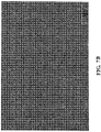
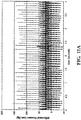
- the microstructure of an expanded fluoropolymer membrane comprises nodes interconnected by fibrils as shown in the scanning electron micrograph image in Figure 7A .
- the fibrils extend from the nodes in a plurality of directions, and the membrane has a generally homogeneous structure.
- Membranes having this microstructure may typically exhibit a ratio of matrix tensile strength in two orthogonal directions of less than 2, and possibly less than 1.5.
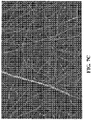
- the expanded fluoropolymer may have a microstructure of substantially only fibrils, such as, for example, depicted in Figure 7B and 7C , as is generally taught by U.S. Patent No. 7,306,729, to Bacino .
- Figure 7C is a higher magnification of the expanded fluoropolymer membrane shown in Figure 7B , and more clearly shows the homogeneous microstructure having substantially only fibrils.
- the expanded fluoropolymer membrane having substantially only fibrils as depicted in Figures 7B and 7C may possess a high surface area, such as greater than 20m 2 /g, or greater than 25m 2 /g, and in some embodiments may provide a highly balanced strength material having a product of matrix tensile strengths in two orthogonal directions of at least 1.5 x 10 5 MPa 2 , and/or a ratio of matrix tensile strengths in two orthogonal directions of less than 2, and possibly less than 1.5.
- the expanded fluoropolymer of the present invention may be tailored to have any suitable thickness and mass to achieve the desired leaflet performance. In some cases, it may be desirable to use a very thin expanded fluoropolymer membrane having a thickness less than 1.0 ⁇ m. In other embodiments, it may be desirable to use an expanded fluoropolymer membrane having a thickness greater than 0.1 ⁇ m and less than 20 ⁇ m.
- the expanded fluoropolymer membranes can posess a specific mass less than about 1g/m 2 to greater than about 50g/m 2 .
- Membranes according to an embodiment of the invention can have matrix tensile strengths ranging from about 50 MPa to about 400 MPa or greater, based on a density of about 2.2 g/cm 3 for PTFE.
- Composites according to one embodiment can include fluoropolymer membranes having thicknesses ranging from about 500 ⁇ m to less than 0.3 ⁇ m.
- the expanded fluoropolymer membrane combined with elastomer provides the elements of the present invention with the performance attributes required for use in high-cycle flexural implant applications, such as heart valve leaflets, in at least several significant ways.
- the addition of the elastomer improves the fatigue performance of the leaflet by eliminating or reducing the stiffening observed with ePTFE-only materials.
- the elastomer occupies substantially all of the pore volume or space within the porous structure of the expanded fluoropolymer membrane.
- the elastomer is present in substantially all of the pores of the at least one fluoropolymer layer. Having elastomer filling the pore volume or present in substantially all of the pores reduces the space in which foreign materials can be undesirably incorporated into the composite.
- An example of such foreign material is calcium. If calcium becomes incorporated into the composite material, as used in a heart valve leaflet, for example, mechanical damage can occur during cycling, thus leading to the formation of holes in the leaflet and degradation in hemodynamics.
- the elastomer that is combined with the ePTFE is a thermoplastic copolymer of tetrafluoroethylene (TFE) and perfluoromethyl vinyl ether (PMVE), such as described in U.S. Patent No. 7,462,675 .
- TFE tetrafluoroethylene
- PMVE perfluoromethyl vinyl ether
- the elastomer is combined with the expanded fluoropolymer membrane such that the elastomer occupies substantially all of the void space or pores within the expanded fluoropolymer membrane. This filling of the pores of the expanded fluoropolymer membrane with elastomer can be performed by a variety of methods.
- a method of filling the pores of the expanded fluoropolymer membrane includes the steps of dissolving the elastomer in a solvent suitable to create a solution with a viscosity and surface tension that is appropriate to partially or fully flow into the pores of the expanded fluoropolymer membrane and allow the solvent to evaporate, leaving the filler behind.
- a method of filling the pores of the expanded fluoropolymer membrane includes the steps of delivering the filler via a dispersion to partially or fully fill the pores of the expanded fluoropolymer membrane;
- a method of filling the pores of the expanded fluoropolymer membrane includes the steps of bringing the porous expanded fluoropolymer membrane into contact with a sheet of the elastomer under conditions of heat and/or pressure that allow elastomer to flow into the pores of the expanded fluoropolymer membrane.
- a method of filling the pores of the expanded fluoropolymer membrane includes the steps of polymerizing the elastomer within the pores of the expanded fluoropolymer membrane by first filling the pores with a prepolymer of the elastomer and then at least partially curing the elastomer.
- biocompatible polymers which may be suitable for use in this invention may include but not be limited to the groups of urethanes, silicones(organopolysiloxanes), copolymers of silicon-urethane, styrene/isobutylene copolymers, polyisobutylene, polyethylene-co-poly(vinyl acetate), polyester copolymers, nylon copolymers, fluorinated hydrocarbon polymers and copolymers or mixtures of each of the foregoing.
- Heart valve leaflets were formed from a composite material having an expanded fluoropolymer membrane and an elastomeric material and joined to a metallic balloon expandable stent, as described by the following process:
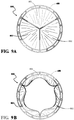
- the resulting valve assembly 800 includes leaflets 802 formed from a composite material with at least one fluoropolymer layer having a plurality of pores and an elastomer present in substantially all of the pores of the at least one fluoropolymer layer.
- Each leaflet 802 is movable between a closed position, shown illustratively in Figure 9A , in which blood is prevented from flowing through the valve assembly, and an open position, shown illustratively in Figure 9B , in which blood is allowed to flow through the valve assembly.
- the leaflets 802 of the valve assembly 800 cycle between the closed and open positions generally to regulate blood flow direction in a human patient
- valve leaflets in each valve assembly were characterized on a real-time pulse duplicator that measured typical anatomical pressures and flows across the valve, generating an initial or "zero fatigue" set of data for that particular valve assembly.
- the valve assembly was then transferred to a high-rate fatigue tester and was subjected to approximately 207 million cycles. After each block of about 100 million cycles, the valve was then returned to the real-time pulse duplicator and the performance parameters re-measured.
- valve assembly was then removed from the flow pulse duplicator system and placed into a high-rate fatigue tester.
- a Six Position Heart Valve Durability Tester, Part Number M6 was supplied by Dynatek, Galena, MO, USA and was driven by a Dynatek Dalta DC 7000 Controller. This high rate fatigue tester displaces fluid through a valve assembly with a typical cycle rate of about 780 cycles per minute.
- the valve assembly can be visually examined using a tuned strobe light.
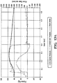
- the pressure drop across the closed valve can also be monitored as displayed in Figures 11A and 11B . Shown in Figures 11A and 11B is a typical data set verifying that the high-rate fatigue tester was producing consistent pressure wave forms.
- valve assembly was continuously cycled and periodically monitored for visual and pressure drop changes. After approximately 200 million cycles, the valve assembly was removed from the high-rate tester and returned to the real-time pulse duplicator. The pressure and flow data were collected and compared to the original data collected.
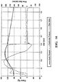
- Shown in Figure 12A is a screen shot displaying typical measured data outputs from the real-time heart flow pulse duplicator system. Shown are Ventricular Pressures, Aortic Pressures and Flow Rate.
- the initial or zero fatigue data for a particular valve is shown illustratively in Figure 12A .
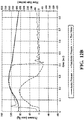
- the same measurements were taken and data were collected for the same particular valve after 207 million cycles.
- the 207 million cycle data for the particular valve is shown illustratively in Figure 12B . Both sets of measurements were taken at 5 liters per minute flow rate and 70 cycles per minute rate. Comparing Figures 12A and 12B , it should be readily appreciated that the waveforms are substantially similar, indicating no substantial change in the valve leaflet performance after about 207 million cycles.
- valve leaflets constructed according to the embodiments described herein exhibited no physical or mechanical degradation, such as tears, holes, permanent set and the like, after 207 million cycles. As a result, there was also no observable change or degradation in the closed and open configurations of the valve leaflets even after 207 million cycles.
- a heart valve having polymeric leaflets joined to a rigid metallic frame was constructed according to the following process:
- a valve frame 930 was laser cut from a length of 316 stainless steel tube with an outside diameter of about 25.4mm and a wall thickness of about 0.5mm in the shape shown in Figure 15 .
- the valve frame 930 extends axially between a bottom end 932 and an opposite top end defined generally by a plurality of axially extending, generally spire shaped posts 934 corresponding to the number of leaflets in the intended finished valve assembly (not shown).
- three posts 934 are formed in the valve frame 930.
- valve frame 930 Two layers of an about 4 ⁇ m thick film of FEP (not shown) was wrapped around the valve frame 930 and baked in an oven for about 30 minutes at about 270°C and allowed to cool.
- the resulting covered valve frame (for clarity, shown uncovered and indicated at 930) was then slid onto the mandrel 900 so that the complementary features between the valve frame 930 and mandrel 900 are nested together, as shown in Figure 16 .
- a leaflet material was then prepared having a membrane layer of ePTFE imbibed with a fluoroelastomer. More specifically, the membrane layer of ePTFE was manufactured according to the general teachings described in U.S. Patent No. 7,306,729 .
- the ePTFE membrane was tested in accordance with the methods described in the Appendix.
- the ePTFE membrane had a mass per area of about 0.57 g/m 2 , a porosity of about 90.4%, a thickness of about 2.5 ⁇ m, a bubble point of about 458 KPa, a matrix tensile strength of about 339 MPa in the longitudinal direction and about 257 MPa in the transverse direction.
- This membrane was imbibed with the same fluoroelastomer as described in Example 1.
- the fluoroelastomer was dissolved in Novec HFE7500, 3M, St Paul, MN, USA in an about 2.5% concentration.
- the solution was coated using a mayer bar onto the ePTFE membrane (while being supported by a polypropylene release film) and dried in a convection oven set to about 145°C for about 30 seconds. After two coating steps, the resulting composite material of ePTFE/fluoroelastomer had a mass per area of about 3.6 g/m 2 .
- the composite material (not shown) was then wound around the assembled mandrel 900 and valve frame 930.
- a total of 20 layers of the ePTFE/fluoroelastomer composite was used. Any excess composite material that extended beyond the ends of mandrel 900 were twisted and pressed lightly against the ends 902, 904 of the mandrel 900.
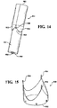
- the composite material wrapped mandrel was then mounted in a pressure vessel so that a vent port 906 ( Figure 14 ) in the base or second end 904 of the mandrel 900 was plumbed to atmosphere.
- the vent port 906 extends from the second end 904 axially through the mandrel 900 and communicates to a generally orthogonally extending vent port 908 that extends through the outer surface 910 of the mandrel 900.
- the ePTFE/fluoroelastomer composite was trimmed circumferentially in two places: first, at the bottom end 932 of the valve frame 930, and second, near the top end of the valve frame 930 along a circle generally intersecting near the midpoint of each post 934.
- the resulting valve assembly 940 consisting of the valve frame 930 and the trimmed composite material was separated from and slid off the mandrel
- the molded valve assembly 940 includes the valve frame 930 and a plurality of leaflets 950 formed from the trimmed composite material.
- the valve assembly 940 included three leaflets.
- each leaflet 950 in the valve assembly 940 was approximately 40 ⁇ m thick.
- adjacent leaflets about each post were bonded together.
- the adjacent leaflets 950a, 950b were wrapped around the post 934 and bonded together to form a seam 954.
- the seam 954 had a depth 956 extending to at least about 2mm from the post 934.
- an attachment member 952 was fixedly secured to inner surfaces of the adjacent leaflets 950a, 950b thereby bridging the seam 954 between the adjacent leaflets 950a, 950b.
- the attachment member 952 was generally rectangular. It should be appreciated, however, that other shapes for the attachment member may be utilized.
- the attachment member 952 was formed from the same type of composite material used to form the leaflets 950.
- the attachment member 952 was fixedly secured to the inner surfaces of the adjacent leaflets 950a, 950b using the fluoroelastomer solution previously described. These steps were repeated for the other pairs of adjacent leaflets of the valve assembly.
- Example 2 The performance and durability of the valve leaflets in this example were analyzed in the same manner as described in Example 1.
- the valve assembly was initially characterized on the same real-time pulse duplicator as described in Example 1 that measured typical anatomical pressures and flows across the valve, generating an initial or "zero fatigue" set of data for that particular valve assembly.
- the valve was then subjected to accelerated testing as in Example 1. After about 79 million cycles, the valve was removed from the high rate fatigue tester and the hydrodynamic performance again characterized as in Example 1. The valve was removed finally at about 198 million cycles. Pressure drop, EOA and regurgitant fraction measured at about 79 million cycles and about 198 cycles are summarized in Table 2 below.
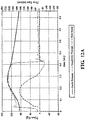
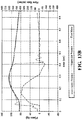
- Figures 13A and 13B display similar results for a similar valve.
- Figure 13A is a graph of measured data output from the heart flow pulse duplicator system taken after about 79 million cycles. The same measurements were taken for the similar valve after about 198 million cycles, a graph of which is shown illustratively in Figure 13B . Both sets of measurements were taken at about 4 liters per minute flow rate and about 70 cycles per minute rate. Comparing Figures 13A and 13B , it should be again appreciated that the waveforms are significantly similar, indicating no substantial change in the valve leaflet performance after about 198 million cycles. Pressure drop, effective orifice area (EOA), and regurgitant fraction measured at 0, about 79, and about 198 million cycles are summarized in Table 2 below.
- EOA effective orifice area
- a heart valve having polymeric leaflets joined to a rigid metallic frame was constructed according to the following process:
- a cushion member is provided between at least a portion of the frame and at least a portion of the leaflet to minimize stress related to direct contact between the frame and the leaflet.
- a composite fiber of ePTFE and silicone was created by first imbibing an ePTFE membrane with silicone MED-6215 (NuSil, Carpinteria, CA, USA), slitting it to a width of about 25 mm, and rolling into a substantially round fiber. The ePTFE used in this fiber was tested in accordance with the methods described in the Appendix.
- the ePTFE membrane had a bubble point of about 217 KPa, a thickness of about 10 ⁇ m, a mass per area of about 5.2 g/m 2 , a porosity of about 78%, a matrix tensile strength in one direction of about 96 MPa, and a matrix tensile strength of about 55 MPa in an orthogonal direction.
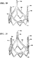
- the composite fiber 966 was wrapped around each of the posts 964 of the frame 960 as shown in Figure 20 .
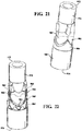
- a mandrel 970 was formed using stereolithography in a shape shown in Figure 21 .
- the mandrel 970 has a first end 972 and an opposite second end 974, and extends longitudinally therebetween.
- the mandrel 970 has an outer surface 980 having three (two shown) generally arcuate, convex lobes 982, each generally for forming leaflets (not shown) of a finished valve assembly (not shown).
- the outer surface 980 also includes a frame seating area 984 for positioning the frame (960 in Figure 19 ) relative to the convex lobes 982 prior to formation of the valve leaflets onto the valve frame.
- the mandrel 970 was then spray coated with a PTFE mold release agent.
- Four layers of the ePTFE membrane previously described in this example were wrapped around the mandrel.
- MED-6215 was wiped onto the ePTFE and allowed to wet into and substantially fill the pores of the ePTFE. Excess MED-6215 was blotted off and the frame 960 with the composite fiber 966 wrapped posts 964 was positioned on the mandrel 970 along the frame seating area 984, as shown in Figure 22 .
- Silicone MED-4720, NuSil, Carpinteria, CA, USA was placed along the top edges 968 of the frame 960 and along the posts 964 of the frame 960 to create a strain relief within the leaflet (not shown).
- ePTFE Eight additional layers of ePTFE were wrapped around the frame 960 and mandrel 970. Additional MED-6215 was wiped onto the ePTFE and allowed to wet into and substantially fill the pores of the ePTFE. Another 8 layers of ePTFE were wrapped around the frame 960 and mandrel 970. These layers form a blotter to absorb any excess silicone during the molding process and were removed after the silicone had cured.
- Silicone rubber forms (not shown) molded with one surface exactly matching the inverse shape of the mandrel surface were previously fabricated for each of the 3 leaflet-forming features. These forms were spray coated with PTFE mold release and then mated to the matching feature of the mandrel. Approximately 50 wraps of an ePTFE fiber (not shown) were wound around the silicone forms to apply generally radial pressure to the valve against the mandrel.
- This assembly was then placed in an oven at about 100°C for about 1 hour to cure the silicone. After cooling, the fiber and silicone forms were removed, the 8 layers of blotter ePTFE were peeled away and discarded, and the resulting valve (not shown) was slid off of the mandrel. The posts were trimmed using wire cutters and the excess length of leaflet material and excess length of material at the base of the frame was carefully trimmed using scissors to form a completed valve assembly, which is shown and generally indicated at 990 in Figure 23 .
- the valve assembly 990 was formed having the frame or support structure 960; a plurality of leaflets 992 supported on the support structure 960 and movable between open and closed positions to regulate blood flow through the valve assembly 990; and a composite fiber 966 wrapped post 964 located between at least a portion of the support structure 960 and at least a portion of each leaflet 992 to minimize stress in the leaflets due to the coupling and/or proximity of the leaflets to the support structure.
- the cushion member is formed from a composite material with at least one fluoropolymer layer having a plurality of pores and an elastomer present in substantially all of the pores, as described above.
- cushion members may be utilized anywhere along the support structure as necessary to minimize stress in the leaflets due to the coupling and/or proximity of the leaflets to the support structure.
- cushion member(s) may be coupled to the support structure along the parabolically shaped top edge.
- cushion members may be formed as sheets and wrapped around desired locations along the support structure, or be formed from fibers of various cross sectional shapes and sizes.
- the leaflets of the complete valve assembly were measured and determined to have an average thickness at the center of each leaflet of about 120 ⁇ m.
- valve assembly was then characterized for flow performance and subjected to accelerated testing as in Example 1. After each block of about 50 million cycles, the valve assembly was removed from the high rate fatigue tester and the hydrodynamic performance again characterized as in Example 1. The valve assembly was removed finally at about 150 million cycles and demonstrated acceptable performance and no hole formation.
- Example 1 Six valves were constructed in the manner of Example 1 with the exception that the elastomer was not incorporated.
- the ePTFE material was the same as that described in Example 1, but it was not imbibed with the fluoroelastomer copolymer and was instead coated with a discontinuous layer of FEP copolymer that served as a thermoplastic adhesive.
- Valves were constructed as in Example 1 with each leaflet comprising 3 layers of membrane resulting in a final leaflet thickness averaging about 20 ⁇ m. After hydrodynamic characterization, the valves were mounted in the Dynatek accelerated tester described in Example 1. By about 40 million cycles, edge delamination and hole formation in the leaflets was observed and the test was stopped.
- the tooling was then exposed to about 350°C in a convection air oven for about 25 minutes, removed and quenched in a water bath. The three pieces of tooling were then inserted into the stent frame and the leaflets bonded to the valve assembly with FEP as in Example 1.
- Each valve was subjected to high-rate fatigue testing using the real-time heart flow pulse duplicator system, as described above. After about 30 million cycles on one valve and about 40 million cycles on another valve, visual degradation, including stiffening and deformation, was observed and measurable decrease in performance was noted. In addition to the visual and measurable degradation in performance, Table 3 below summarizes the pressure drop, effective orifice area (EOA), and regurgitant fraction measured after about 40 million cycles. Table 3 Number of Cycles (Millions) Pressure Drop (mm Hg) EOA (cm 2 ) Regurgitant Fraction (%) 0 3.9 3.11 8.1 40x10 6 6.5 2.85 14.1
- matrix tensile strength refers to the tensile strength of a porous fluoropolymer specimen under specified conditions. The porosity of the specimen is accounted for by multiplying the tensile strength by the ratio of density of the polymer to the density of the specimen.
- membrane refers to a porous fluoropolymer article
- composite refers to imbibed porous fluoropolymers
- a “leaflet” is a component of an implantable article for regulating blood flow direction.
- Leaflets of the present invention are one or more layers of a composite.
- imbibe used herein refers to any process used to at least partially fill pores with a secondary material.
- the elastomer can be dissolved or degraded and rinsed away using an appropriate solvent in order to measure desired properties.
- elastomer As the term “elastomer” is used herein it defines a polymer, mixture of polymers, or mixture of one or more polymers with one or more non-polymeric components that has the ability to be stretched to at least 1.3 times its original length and to retract rapidly to approximately its original length when released.
- elastomeric is intended to describe a property whereby a polymer displays stretch and recovery properties similar to an elastomer, although not necessarily to the same degree of stretch and/or recovery.
- the polymer can be made to soften, flow, or take on a new shape, without significant degradation or alteration of the polymer's original chemical condition, then the polymer is considered to be a thermoplastic. If only small amounts of material are available it may be necessary to use a hot stage microscope for this determination.
- EOA effective orifice area
- the surface area per unit mass was measured using the Brunauer-Emmett-Teller (BET) method on a Coulter SA3100Gas Adsorption Analyzer, Beckman Coulter Inc. Fullerton CA, USA.
- BET Brunauer-Emmett-Teller
- a sample was cut from the center of the expanded fluoropolymer membrane and placed into a small sample tube.
- the mass of the sample was approximately 0.1 to 0.2 g.
- the tube was placed into the Coulter SA-Prep Surface Area Outgasser (Model SA-Prep, P/n 5102014) from Beckman Coulter, Fullerton CA, USA and purged at about 110°C for about two hours with helium.
- sample tube was then removed from the SA-Prep Outgasser and weighed.
- sample tube was then placed into the SA3100 Gas adsorption Analyzer and the BET surface area analysis was run in accordance with the instrument instructions using helium to calculate the free space and nitrogen as the adsorbate gas.
- Bubble point and mean flow pore size were measured according to the general teachings of ASTM F31 6-03 using a capillary flow Porometer, Model CFP 1500AEXL from Porous Materials, Inc., Ithaca NY, USA.
- the sample membrane was placed into the sample chamber and wet with SilWick Silicone Fluid (available from Porous Materials Inc.) having a surface tension of about 20.1 dynes/cm.
- the bottom clamp of the sample chamber had an about 2.54 cm diameter hole.
- the Capwin software version 7.73.012 the following parameters were set as specified in the table below.
- Parameter Set Point Maxflow (cm 3 /m) 200000 Bublflow(cm 3 /m) 100 F/PT (old bubltime) 50 Minbpress (PSI) 0 Zerotime (sec) 1 V2incr(cts) 10 Preginc (cts) 1 Pulse delay(sec) 2 Maxpre (PSI) 500 Pulse width (sec) 0.2 Mineqtime (sec) 30 Presslew (cts) 10 Flowslew (cts) 50 Eqiter 3 Aveiter 20 Maxpdif (PSI) 0.1 Maxfdif (PSI) 50 Sartp(PSI) 1 Sartf (cm 3 /m) 500
- Membrane thickness was measured by placing the membrane between the two plates of a Käfer FZ1000/30 thickness snap gauge Käfer Messuhrenfabrik GmbH, Villingen-Schwenningen, Germany. The average of the three measurements was reported.
- the presence of elastomer within the pores can be determined by several methods known to those having ordinary skill in the art, such as surface and/or cross section visual, or other analyses. These analyses can be performed prior to and after the removal of elastomer from the leaflet.
- Tensile break load was measured using an INSTRON 122 tensile test machine equipped with flat-faced grips and a 0.445 kN load cell. The gauge length was about 5.08 cm and the cross-head speed was about 50.8 cm/min. The sample dimensions were about 2.54 cm by about 15.24 cm. For longitudinal measurements, the longer dimension of the sample was oriented in the highest strength direction. For the orthogonal MTS measurements, the larger dimension of the sample was oriented perpendicular to the highest strength direction. Each sample was weighed using a Mettler Toledo Scale Model AG204, then the thickness measured using the Käfer FZ1000/30 snap gauge. The samples were then tested individually on the tensile tester. Three different sections of each sample were measured.
- MTS maximum load/cross-section area
- Bulk density of PTFE density of the porous membrane
- Flexural stiffness was measured by following the general procedures set forth in ASTM D790. Unless large test specimens are available, the test specimen must be scaled down. The test conditions were as follows. The leaflet specimens were measured on a three-point bending test apparatus employing sharp posts placed horizontally about 5.08 mm from one another.
Description
- The invention relates to materials used in medical implants. More particularly, the invention relates to a biocompatible material suitable for use in high-cycle flexural applications including artificial heart valves.
- Artificial heart valves preferably should last at least ten years in vivo. To last that long, artificial heart valves should exhibit sufficient durability for at least four hundred million cycles or more. The valves, and more specifically heart valve leaflets, must resist structural degradation including the formation of holes, tears, and the like as well as adverse biological consequences including calcification and thrombosis.
- Fluoropolymers, such as expanded and non-expanded forms of polytetrafluoroethylene (PTFE), modified PTFE, and copolymers of PTFE, offer a number of desirable properties, including excellent inertness and superior biocompatibility, and, therefore make ideal candidate materials. PTFE and expanded PTFE (ePTFE) have been used to create heart valve leaflets. It has been shown, however, that PTFE stiffens with repeated flexure, which can lead to unacceptable flow performance. Failure due to formation of holes and tears in the material has also been observed. A variety of polymeric materials has previously been employed as prosthetic heart valve leaflets. Failure of these leaflets due to stiffening and hole formation occurred within two years of implant. Efforts to improve leaflet durability by thickening the leaflets resulted in unacceptable hemodynamic performance of the valves, that is, the pressure drop across the open valve was too high.
- As such, it remains desirable to provide a biocompatible artificial heart valve design that lasts beyond ten years in vivo by exhibiting sufficient durability for at least about four hundred million cycles of flexure or more.
-
EP0293090 provides porous biologically compatible materials capable of being formed into surgical implants, comprising layers of poly(tetrafluoroethylene) and elastomer, having superior compliance, strength, elasticity and suturability. The materials comprise a first layer of poly(tetrafluoroethylene), a second layer of poly(tetrafluoroethylene)/elastomer mixture, optionally a third layer of elastomer, and an optional fourth layer of a monomer fibrous elastomer matrix. -
US2004024448 describes a medical device with at least a partial surface coating of a thermoplastic copolymer of tetrafluoroethylene and perfluoroalkylvinylether that is free of cross-linking monomers and curing agents. -
US2004019374 describes a medical device, and in particular, to a stent-based valve. The valve includes a radially expandable structural frame comprising a proximal and distal anchors formed from a lattice of interconnected elements, and having a substantially cylindrical configuration with first and second open ends and a longitudinal axis extending there between. One or more cantilevered valve struts are attached directly or indirectly to the proximal anchor. The stent based valve also comprises one or more connecting members attached between the proximal and distal anchors. A biocompatible valve assembly is coaxially disposed and attached to the proximal anchor and extends in the longitudinal direction along the one or more connecting members. - According to one aspect of the invention, an implantable article is provided for regulating blood flow direction in a human patient. In one embodiment, the implantable article includes a leaflet
t comprising a composite material with at least one fluoropolymer layer having a plurality of pores and an elastomer present in substantially all of the pores of the at least one fluoropolymer layer, wherein the composite material comprises less than about 80% fluoropolymer by weight. - In another embodiment, the implantable article includes a support structure; a leaflet supported on the support structure and movable between open and closed positions to regulate blood flow through the implantable article; and a cushion member located between at least a portion of the support structure and at least a portion of the leaflet, wherein the cushion member is formed from a composite material with at least one fluoropolymer layer having a plurality of pores and an elastomer present in substantially all of the pores.
- In another embodiment, the implantable article includes a generally annular shaped support structure having a first end and an opposite second end. The first end of the support structure has a longitudinally extending post. A sheet of leaflet material extends along an outer periphery of the support structure and forms first and second leaflets extending along on opposite sides of the post. A cushion member is coupled to the post and provides a cushion between the post and the leaflets to minimize stress and wear on the leaflets as the leaflets cycle between open and closed positions.
- The accompanying drawings are included to provide a further understanding of the invention and are incorporated in and constitute a part of this specification, illustrate embodiments of the invention, and together with the description serve to explain the principles of the invention.
-
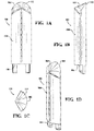
Figures 1A, 1B, 1C, and 1D are front, side and top elevational views, and a perspective view, respectively, of a tool for forming a heart valve leaflet; -
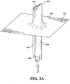
Figure 2A is a perspective view of a cushion pad being stretched over a leaflet tool; -
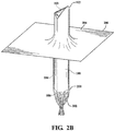
Figure 2B is a perspective view of a release layer being stretched over the cushion pad covered leaflet tool inFigure 2A ; -
Figures 3A, 3B and 3C are top, side and front elevational views illustrating a step in the formation of a valve leaflet, in which the leaflet tool covered by the cushion pad and release layer (shown inFigures 2A and2B , respectively) is positioned over a composite material for cutting and further assembly; -
Figure 4 is a top elevational view of a tri-leaflet assembly prior to cutting excess leaflet material; -
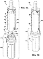
Figure 5A is a perspective view of the tri-leaflet assembly and a base tool. -
Figure 5B is a perspective view of the tri-leaflet assembly and base tool aligned and assembled to form a base tool assembly; -
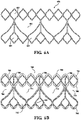
Figure 6A is a flattened plane view of a stent frame or support structure; -
Figure 6B is a flattened plane view of the support structure covered in a polymer coating; -
Figures 7A ,7B and7C are scanning electron micrograph images of expanded fluoropolymer membranes used to form the valve leaflets; -
Figure 8 is a perspective view of a valve assembly; -
Figures 9A and 9B are top elevational views of the heart valve assembly ofFigure 8 shown illustratively in closed and open positions, respectively; -
Figure 10 is a graph of measured outputs from a heart flow pulse duplicator system used for measuring performance of the valve assemblies; -
Figures 11A and11B are a graph and data chart of measured outputs from a high rate fatigue tester used for measuring performance of the valve assemblies; -
Figures 12A and12B are graphs of measured outputs from the heart flow pulse duplicator system taken while testing valve assemblies according to the invention at zero cycles and after about 207 million cycles, respectively; -
Figures 13A and13B are graphs of measured outputs from the heart flow pulse duplicator system taken while testing valve assemblies at about 79 million cycles and after about 198 million cycles, respectively; -
Figure 14 is a perspective view of a mandrel for manufacturing a heart valve assembly; -
Figure 15 is a perspective view of a valve frame for a heart valve; -
Figure 16 is a perspective view of the valve frame ofFigure 15 nested together with the mandrelFigure 14 ; -
Figure 17 is a perspective view of a molded valve; -
Figure 18 is a perspective view of a molded valve, showing an attachment member for reinforcing a bond between adjacent valve leaflets and a post of a valve frame; -
Figure 19 is a perspective view of a valve frame; -
Figure 20 is a perspective view of the valve frame ofFigure 19 with posts that are cushion-wrapped; -
Figure 21 is a perspective view of a stereolithography-formed mandrel; -
Figure 22 is a perspective view of the cushion-wrapped valve frame ofFigure 20 mounted onto the mandrel ofFigure 21 ; and -
Figure 23 is a perspective view of a valve having valve leaflets coupled to and supported on the cushion-wrapped valve frame ofFigure 20 . - Definitions for some terms used herein are provided below in the Appendix.
- The present invention addresses a long-felt need for a material that meets the durability and biocompatibility requirements of high-cycle flexural implant applications, such as heart valve leaflets. It has been observed that heart valve leaflets formed from porous fluoropolymer materials or, more particularly, from ePTFE containing no elastomer suffer from stiffening in high-cycle flex testing and animal implantation.
- In one embodiment, described in greater detail below, the flexural durability of porous fluoropolymer heart valve leaflets was significantly increased by adding a relatively high-percentage of relatively lower strength elastomer to the pores. Optionally, additional layers of the elastomer may be added between the composite layers. Surprisingly, in embodiments wherein porous fluoropolymer membranes are imbibed with elastomer the presence of the elastomer increased overall thickness of the leaflet, the resulting increased thickness of the fluoropolymer members due to the addition of the elastomer did not hinder or diminish flexural durability. Further, after reaching a minimum percent by weight of elastomer, it was found that fluoropolymer members in general performed better with increasing percentages of elastomer resulting in significantly increased cycle lives exceeding 40 million cycles in vitro, as well as by showing no signs of calcification under certain controlled laboratory conditions.
- A material according to one embodiment includes a composite material comprising an expanded fluoropolymer membrane and an elastomeric material. It should be readily appreciated that multiple types of fluoropolymer membranes and multiple types of elastomeric materials can be combined. It should also be readily appreciated that the elastomeric material can include multiple elastomers, multiple types of non-elastomeric components, such as inorganic fillers, therapeutic agents, radiopaque markers, and the like.
- In one embodiment, the composite material includes an expanded fluoropolymer material made from porous ePTFE membrane, for instance as generally described in
U.S. Patent No. 7,306,729 . - The expandable fluoropolymer, used to form the expanded fluoropolymer material described, may comprise PTFE homopolymer. In alternative embodiments, blends of PTFE, expandable modified PTFE and/or expanded copolymers of PTFE may be used. Non-limiting examples of suitable fluoropolymer materials are described in, for example,
U.S. Patent No. 5,708,044, to Branca ,U.S. Patent No. 6,541,589, to Baillie ,U.S. Patent No. 7,531,611, to Sabol et al. ,U.S. Patent Application No. 11/906,877, to Ford , andU.S. Patent Application No. 12/410,050, to Xu et al. - The expanded fluoropolymer of the present invention may comprise any suitable microstructure for achieving the desired leaflet performance. In one embodiment, the expanded fluoropolymer may comprise a microstructure of nodes interconnected by fibrils, such as described in
U.S. Patent No. 3,953,566 to Gore . In one embodiment, the microstructure of an expanded fluoropolymer membrane comprises nodes interconnected by fibrils as shown in the scanning electron micrograph image inFigure 7A . The fibrils extend from the nodes in a plurality of directions, and the membrane has a generally homogeneous structure. Membranes having this microstructure may typically exhibit a ratio of matrix tensile strength in two orthogonal directions of less than 2, and possibly less than 1.5. - In another embodiment, the expanded fluoropolymer may have a microstructure of substantially only fibrils, such as, for example, depicted in
Figure 7B and7C , as is generally taught byU.S. Patent No. 7,306,729, to Bacino .Figure 7C is a higher magnification of the expanded fluoropolymer membrane shown inFigure 7B , and more clearly shows the homogeneous microstructure having substantially only fibrils. The expanded fluoropolymer membrane having substantially only fibrils as depicted inFigures 7B and7C , may possess a high surface area, such as greater than 20m2/g, or greater than 25m2/g, and in some embodiments may provide a highly balanced strength material having a product of matrix tensile strengths in two orthogonal directions of at least 1.5 x 10⁵ MPa2, and/or a ratio of matrix tensile strengths in two orthogonal directions of less than 2, and possibly less than 1.5. - The expanded fluoropolymer of the present invention may be tailored to have any suitable thickness and mass to achieve the desired leaflet performance. In some cases, it may be desirable to use a very thin expanded fluoropolymer membrane having a thickness less than 1.0 µm. In other embodiments, it may be desirable to use an expanded fluoropolymer membrane having a thickness greater than 0.1 µm and less than 20 µm. The expanded fluoropolymer membranes can posess a specific mass less than about 1g/m2 to greater than about 50g/m2.
- Membranes according to an embodiment of the invention can have matrix tensile strengths ranging from about 50 MPa to about 400 MPa or greater, based on a density of about 2.2 g/cm3 for PTFE.
- Additional materials may be incorporated into the pores or within the material of the membranes or in between the layers of the membranes to enhance desired properties of the leaflet. Composites according to one embodiment can include fluoropolymer membranes having thicknesses ranging from about 500 µm to less than 0.3 µm.
- The expanded fluoropolymer membrane combined with elastomer provides the elements of the present invention with the performance attributes required for use in high-cycle flexural implant applications, such as heart valve leaflets, in at least several significant ways. For example, the addition of the elastomer improves the fatigue performance of the leaflet by eliminating or reducing the stiffening observed with ePTFE-only materials. In addition, it reduces the likelihood that the material will undergo permanent set deformation, such as wrinkling or creasing, that could result in compromised performance. In one embodiment, the elastomer occupies substantially all of the pore volume or space within the porous structure of the expanded fluoropolymer membrane. In another embodiment the elastomer is present in substantially all of the pores of the at least one fluoropolymer layer. Having elastomer filling the pore volume or present in substantially all of the pores reduces the space in which foreign materials can be undesirably incorporated into the composite. An example of such foreign material is calcium. If calcium becomes incorporated into the composite material, as used in a heart valve leaflet, for example, mechanical damage can occur during cycling, thus leading to the formation of holes in the leaflet and degradation in hemodynamics.
- In one embodiment, the elastomer that is combined with the ePTFE is a thermoplastic copolymer of tetrafluoroethylene (TFE) and perfluoromethyl vinyl ether (PMVE), such as described in
U.S. Patent No. 7,462,675 . As discussed above, the elastomer is combined with the expanded fluoropolymer membrane such that the elastomer occupies substantially all of the void space or pores within the expanded fluoropolymer membrane. This filling of the pores of the expanded fluoropolymer membrane with elastomer can be performed by a variety of methods. In one embodiment, a method of filling the pores of the expanded fluoropolymer membrane includes the steps of dissolving the elastomer in a solvent suitable to create a solution with a viscosity and surface tension that is appropriate to partially or fully flow into the pores of the expanded fluoropolymer membrane and allow the solvent to evaporate, leaving the filler behind. - In another embodiment, a method of filling the pores of the expanded fluoropolymer membrane includes the steps of delivering the filler via a dispersion to partially or fully fill the pores of the expanded fluoropolymer membrane;
- In another embodiment, a method of filling the pores of the expanded fluoropolymer membrane includes the steps of bringing the porous expanded fluoropolymer membrane into contact with a sheet of the elastomer under conditions of heat and/or pressure that allow elastomer to flow into the pores of the expanded fluoropolymer membrane.
- In another embodiment, a method of filling the pores of the expanded fluoropolymer membrane includes the steps of polymerizing the elastomer within the pores of the expanded fluoropolymer membrane by first filling the pores with a prepolymer of the elastomer and then at least partially curing the elastomer.
- After reaching a minimum percent by weight of elastomer, the leaflets constructed from fluoropolymer materials or ePTFE generally performed better with increasing percentages of elastomer resulting in significantly increased cycle lives. In one embodiment, the elastomer combined with the ePTFE is a thermoplastic copolymer of tetrafluoroethylene and perfluoromethyl vinyl ether, such as described in
U.S. Patent No. 7,462,675 , and other references that would be known to those of skill in the art. For instance, in another embodiment shown in Example 1, a leaflet was formed from a composite of 53% by weight of elastomer to ePTFE and was subjected to cycle testing. Some stiffening was observed by around 200 million test cycles, though with only modest effect on hydrodynamics. When the weight percent of elastomer was raised to about 83% by weight, as in the embodiment of Example 2, no stiffening or negative changes in hydrodynamics were observed at about 200 million cycles. In contrast, with non-composite leaflets, i.e. all ePTFE with no elastomer, as in the Comparative Example B, severe stiffening was apparent by 40 million test cycles. As demonstrated by these examples, the durability of porous fluoropolymer members can be significantly increased by adding a relatively high-percentage of relatively lower strength elastomer to the pores of the fluoropolymer members. The high material strength of the fluoropolymer membranes also permits specific configurations to be very thin. - Other biocompatible polymers which may be suitable for use in this invention may include but not be limited to the groups of urethanes, silicones(organopolysiloxanes), copolymers of silicon-urethane, styrene/isobutylene copolymers, polyisobutylene, polyethylene-co-poly(vinyl acetate), polyester copolymers, nylon copolymers, fluorinated hydrocarbon polymers and copolymers or mixtures of each of the foregoing.
- The following non-limiting examples are provided to further illustrate embodiments of the present invention.
- Heart valve leaflets according to one embodiment were formed from a composite material having an expanded fluoropolymer membrane and an elastomeric material and joined to a metallic balloon expandable stent, as described by the following process:
- 1) A thick, sacrificial tooling cushion pad or layer was formed by folding a ePTFE layer over upon itself to create a total of four layers. The ePTFE layer was about 5 cm (2") wide, about 0.5mm (0.02") thick and had a high degree of compressibility, forming a cushion pad. Referring to
Figures 1 and2 , thecushion pad 200 was then stretched (Figure 2 ) onto a leaflet tool, generally indicated at 100. Theleaflet tool 100 has aleaflet portion 102, abody portion 104 and abottom end 106. Theleaflet portion 102 of theleaflet tool 100 has a generally arcuate,convex end surface 103. Thecushion pad 200 was stretched and smoothed over theend surface 103 of theleaflet portion 102 of theleaflet tool 100 by forcing theleaflet tool 100 in the direction depicted by the arrow (Figure 2A ). Aperipheral edge 202 of thecushion pad 200 was stretched over thebottom end 106 of theleaflet tool 100 and twisted to hold thecushion pad 200 in place (Figure 2B ). - 2) Referring to
Figure 2B , arelease layer 204 was then stretched over theleaflet portion 102 of theleaflet tool 100 which in the previous step was covered with thecushion pad 200. In one embodiment, therelease layer 204 was made from a substantially nonporous ePTFE having a layer of fluorinated ethylene propylene (FEP) disposed along an outer surface or side thereof. Therelease layer 204 was stretched over theleaflet tool 100 such that the FEP layer faced toward thecushion pad 200 and the substantially nonporous ePTFE faced outwardly or away from thecushion pad 200. The release layer was about 25 µm thick and of sufficient length and width to allow therelease layer 204 to be pulled over thebottom end 106 of theleaflet tool 100. As with thecushion pad 200 in the previous step, aperipheral edge 206 of therelease layer 204 was pulled toward thebottom end 106 of theleaflet tool 100 and then twisted onto thebottom end 106 of theleaflet tool 100 to retain or hold therelease layer 204 in place. The FEP layer of therelease layer 204 was then spot-melted and thereby fixedly secured to thecushion pad 200, as required, by the use of a hot soldering iron. - 3) The processes of Steps 1) and 2) were repeated to prepare three separate leaflet tools, each having a cushion pad covered by a release layer.
- 4) A leaflet material according to one embodiment was formed from a composite material comprising a membrane of ePTFE imbibed with a fluoroelastomer. A piece of the composite material approximately 10 cm wide was wrapped onto a circular mandrel to form a tube. The composite material was comprised of three layers: two outer layers of ePTFE and an inner layer of a fluoroelastomer disposed therebetween. The ePTFE membrane was manufactured according to the general teachings described in
U.S. Patent No. 7,306,729 . The fluoroelastomer was formulated according to the general teachings described inU.S. Patent No. 7,462,675 . Additional fluoroelastomers may be suitable and are described inU.S. Publication No. 2004/0024448 .
The ePTFE membrane had the following properties: thickness = about 15 µm; MTS in the highest strength direction = about 400 MPa; MTS strength in the orthogonal direction = about 250 MPa; Density = about 0.34 g/cm3; IBP = about 660 KPa.
The copolymer consists essentially of between about 65 and 70 weight percent perfluoromethyl vinyl ether and complementally about 35 and 30 weight percent tetrafluoroethylene.
The percent weight of the fluoroelastomer relative to the ePTFE was about 53%.
The multi-layered composite had the following properties: thickness of about 40 µm; density of about 1.2 g/cm3; force to break/width in the highest strength direction = about 0.953 kg/cm; tensile strength in the highest strength direction = about 23.5 MPa (3,400 psi); force to break/width in the orthogonal direction = about 0.87 kg/cm; tensile strength in the orthogonal direction = about 21.4 MPa (3100 psi), IPA bubble point greater than about 12.3 MPa, Gurley Number greater than about 1,800 seconds, and mass/area = about 14 g/m2.
The following test methods were used to characterize the ePTFE layers and the multi-layered composite.
The thickness was measured with a Mutitoyo Snap Gage Absolute, 12.7 mm (0.50") diameter foot, Model ID-C112E, Serial # 10299, made in Japan. The density was determined by a weight/volume calculation using an Analytical Balance Mettler PM400 New Jersey, USA. The force to break and tensile strengths were measured using an Instron Model #5500R Norwood, MA,load cell 50 kg, gage length = 25.4 cm, crosshead speed = 25 mm/minute (strain rate = 100% per minute) with flat faced jaws. The IPA Bubble Point was measured by an IPA bubble point tester, Pressure Regulator Industrial Data Systems Model LG-APOK, Salt Lake City, UT, USA, with a Ramp Rate of 1.38 KPa/s (0.2 psi/s), 3.14 cm2 test area. The Gurley Number was determined as the time in seconds for 100 cm3 of air to flow through a 6.45 cm2 sample at 124 mm of water pressure using a Gurley Tester, Model #4110, Troy, NY, USA.
Unless otherwise noted, these test methods were used to generate the data in subsequent examples.
Layers of the composite material, each having two outer layers of ePTFE and an inner layer of a fluoroelastomer disposed therebetween, was wrapped onto a mandrel having a diameter of about 28 mm (1.1") such that the higher strength direction of the membrane was oriented in the axial direction of the mandrel. In one embodiment, four layers of the composite material were wrapped in a non-helical, generally circumferential fashion onto the mandrel. The composite material had a slight degree of tackiness that allowed the material to adhere to itself. While still on the mandrel, the composite material was slit longitudinally generally along the mandrel long axis to form a sheet about 10 cm (4") by about 90 mm (3.5"). - 5) The resulting sheet of leaflet material (or composite material from Step 4) was then cut and wrapped onto the
leaflet tool 100 having acushion pad 200 covered by arelease layer 204. More specifically, as shown inFigures 3A - 3C , theleaflet material 300 was placed onto a flat cutting surface. Theleaflet tool 100 with thecushion pad 200 andrelease layer 204 was then aligned onto theleaflet material 300 approximately as shown. Fourslits leaflet material 300 with a razor blade. One pair ofslits leaflet tool 100 and terminates at oneedge 300a of theleaflet material 300, and the other pair ofslits leaflet tool 100 and terminates at anopposite edge 300b of theleaflet material 300. Theslits leaflet portion 102 of theleaflet tool 100. Theslits leaflet tool 100. It should be appreciated that the widths of the individual slits are shown not to scale. Theslits leaflet material 300 resulted in the formation of afolding portion 310, a pair ofstraps leaflet material 315. Thefolding portions 310 were then folded in the general direction indicated by thearrows 316 inFigure 3 and smoothed over theleaflet tool 100, which was covered by thecushion pad 200 and therelease layer 204 in the previous steps. - 6) The
leaflet material 315 was then stretched and smoothed over theleaflet portion 102, particularly theend surface 103 of theleaflet tool 100. The Steps 4) and 5) were repeated to form three separate leaflet assemblies. The threeleaflet assemblies tri-leaflet assembly 400, as shown inFigure 4 . Shown are the threeseparate leaflet assemblies leaflet material 315 extending generally radially beyond the periphery of thetri-leaflet assembly 400. - 7) A base tool was then provided having cavities for engaging the end surfaces of the leaflet tools of the tri-leaflet assembly and trimming the excess leaflet area to form three leaflets. Referring to
Figure 5A , the base tool is generally indicated at 500 and extends longitudinally between anend 501 and an oppositebottom end 503. Threeconcave cavities end 501 of thebase tool 500. Eachconcave cavity end surface 103 of one of the threeleaflet assemblies elements base tool 500. Eachelement concave cavities
Thebase tool 500 was then prepared having a compression pad and a release layer (not shown) similar to how the leaflet tool was prepared inSteps 1 and 2. As described for each leaflet tool inSteps 1 and 2, the compression pad and the release layer were similarly stretched and affixed to thebase tool 500 to form a base tool assembly. - 8) Referring to
Figure 5B , the base tool assembly (illustrated for convenience as thebase tool 500 without showing the cushion pad and the release layer) and the tri-leaflet assembly, generally indicated at 400, were then generally axially aligned together so that the end surface (not shown) of eachleaflet tool 100 was seated into one of the concave cavities (not shown) in theend 501 of the base tool, generally indicated at 500, to form a combined tool assembly. - 9) A metallic balloon expandable stent was then fabricated. A tube of 316 stainless steel having a wall thickness of about 0.5mm (0.020") and a diameter of about 2.5cm (1.0") was laser cut. A pattern was cut into the tube to form an annular-shaped cut stent frame or support structure, which is generally indicated at 600 and shown illustratively in a flat, plane view in
Figure 6a . Thesupport structure 600, includes a plurality of smallclosed cells 602, a plurality of largeclosed cells 604, and a plurality of leaflet closedcells 606. Note that one of the plurality of leaflet closedcells 606 appears as an open cell inFigure 6A due to the flat plane view. Thecells support structure 600. - 10) Polymeric materials were then adhered to the laser cut stent frame. First, a sacrificial compression layer of ePTFE membrane was wrapped without overlap onto a mandrel (not shown) having a diameter of about 2.5 cm (1.0"). The sacrificial compression layer of ePTFE membrane had a thickness of about 0.5 mm (0.02") and a width of about 10 cm (4"), and was compliant and compressible to provide a soft, sacrificial compression layer.
- 11) Four layers of a substantially nonporous, ePTFE film were then wrapped onto the mandrel on top of the compression layer membrane. The substantially nonporous, ePTFE film had a thickness of about 25 µm (0.001"), was about 10 cm (4") wide and had a layer of FEP on one side. The substantially nonporous, ePTFE film was wrapped with the FEP facing away from the mandrel. The substantially nonporous, ePTFE film had the properties of the release layer previously described in Step 2).
- 12) A thin film of type 1 (ASTM D3368) FEP was constructed using melt extrusion and stretching. An additional 10 layers of this type 1 (ASTM D3368) FEP film was added to the mandrel, which was previously wrapped in the compression layer membrane in
Step 10 and the four layers of substantially nonporous, ePTFE film inStep 11. The type 1 (ASTM D3368) FEP film was about 40 µm (0.0016") thick and was about 7.7 cm (3") wide. - 13) The wrapped mandrel was then heat treated in an air convection oven at about 320 °C for about 5 minutes and allowed to cool.
- 14) The support structure (indicated at 600 in
Figure 6A ) was then placed onto the heat treated and wrapped mandrel. Two additional layers of type 1 (ASTM D3368) FEP film (provided in Step 12) were then wrapped onto the support structure, which was previously placed on the wrapped mandrel. - 15) The wrapped mandrel and the support structure supported thereon were then heat treated in an air convection oven at about 320 °C for about 10 minutes and allowed to cool, forming a polymeric-coated support structure.
- 16) The polymeric-coated support structure was then trimmed with a scalpel to form a trimmed stent frame, which is generally indicated at 700 and shown illustratively in a flat, plane view in
Figure 6B . More specifically, in one manner, the polymeric coating was trimmed about 2 mm (0.08") past the edges of the support structure (600,Figure 6A ) to form a variety of edge profiles 708. In another manner, the polymeric coating was allowed to span entire cells to form a web in each cell. In either case, thesupport structure 600 was fully encapsulated within apolymeric coating 702 to form the trimmedstent frame 700. The trimmedstent frame 700 includes a plurality ofleaflet openings 704 corresponding in number and generally in shape to the plurality of leaflet closed cells 606 (Figure 6A ). Further, aslit 706 is formed in thepolymeric coating 702 of each of the small closed cells as shown inFigure 6B . Specifically, each slit 706 is linear and generally parallel to a longitudinal center axis (not shown) of the annular-shapedsupport structure 600. - 17) The trimmed stent frame was then placed onto the combined tool assembly from Step 8. The leaflet portions (102) of the leaflet tools were aligned to the leaflet openings (704 in
Figure 6B ) in the trimmed stent frame. The three excess leaflet material areas (315 inFigure 4 ) were pulled through the leaflet openings of the stent frame. Each of the three pairs of straps (312, 314 inFigure 3A ) was pulled through one of the slits (706 inFigure 6B ) and wrapped around the trimmed stent frame. Each pair of straps were wrapped in opposing directions relative to each other. The six straps were then heat tacked to the trimmed stent frame using a hot soldering iron. - 18) The combined tool assembly (Step 8) and the trimmed stent frame having the wrapped and heat tacked straps were then mounted into a rotary chuck mechanism. The rotary chuck mechanism was then adjusted to apply a light, longitudinal compressive load. The excess leaflet material areas (315 in
Figure 4 ) were then heat tacked to the base tool (500 inFigure 5 ) using a hot soldering iron. - 19) The combined tools of Step 18 were then wrapped with an additional 2 layers of type 1 (ASTM D3368) FEP film (from Step 12). Three additional layers of the composite (Step 4) were then overwrapped and tacked down to the trimmed stent frame.
- 20) In preparation for a final heat treat, release and sacrificial layers of a compression tape and compression fiber were applied both circumferentially and longitudinally to the assembly from Step 19. The compression tape/fiber contact and compress the assembly both circumferentially and longitudinally during the subsequent heat treat. A sacrificial layer of compression tape was circumferentially wrapped in a helical fashion onto the assembly from Step 19. This compression tape had the properties of the sacrificial compression layer of ePTFE previously described in
Step 10. An ePTFE compression fiber was then tightly wrapped onto the compression tape. Approximately 100 turns of the compression fiber were circumferentially applied in a closely spaced helical pattern. The ePTFE compression fiber was about 1 mm (0.04") in diameter and was structured to shrink longitudinally when sufficiently heated. The clamped assembly was then removed from the rotary chuck mechanism. Three layers of sacrificial compression tape were then wrapped in a longitudinal fashion around the assembly. Approximately 20 wraps of the compression fiber was then longitudinally wrapped over the longitudinal compression tape. - 21) The assembly from
Step 20 was then heat treated in an air convection oven at about 280°C for about 90 minutes and then room temperature water quenched. This heat treatment step facilitates the flow of the thermoplastic fluoroelastomer into the pores of the ePTFE membrane used to create the leaflet material described in step 4. - 22) The sacrificial compression tapes/fibers were then removed. The polymeric materials were trimmed to allow the leaflet and base tools to be separated. The stent polymeric layers were then trimmed to allow removal of the stent frame with the attached leaflets. The leaflets were then trimmed, resulting in a valve assembly as shown in
Figure 8 and generally indicated at 800. - The resulting
valve assembly 800, according to one embodiment, includesleaflets 802 formed from a composite material with at least one fluoropolymer layer having a plurality of pores and an elastomer present in substantially all of the pores of the at least one fluoropolymer layer. Eachleaflet 802 is movable between a closed position, shown illustratively inFigure 9A , in which blood is prevented from flowing through the valve assembly, and an open position, shown illustratively inFigure 9B , in which blood is allowed to flow through the valve assembly. Thus, theleaflets 802 of thevalve assembly 800 cycle between the closed and open positions generally to regulate blood flow direction in a human patient, - The performance of the valve leaflets in each valve assembly was characterized on a real-time pulse duplicator that measured typical anatomical pressures and flows across the valve, generating an initial or "zero fatigue" set of data for that particular valve assembly. The valve assembly was then transferred to a high-rate fatigue tester and was subjected to approximately 207 million cycles. After each block of about 100 million cycles, the valve was then returned to the real-time pulse duplicator and the performance parameters re-measured.
- The flow performance was characterized by the following process:
- 1) The valve assembly was potted into a silicone annular ring (support structure) to allow the valve assembly to be subsequently evaluated in a real-time pulse duplicator. The potting process was performed according to the recommendations of the pulse duplicator manufacturer (ViVitro Laboratories Inc., Victoria BC, Canada)
- 2) The potted valve assembly was then placed into a real-time left heart flow pulse duplicator system. The flow pulse duplicator system included the following components supplied by VSI Vivitro Systems Inc., Victoria BC, Canada: a Super Pump, Servo Power Amplifier Part Number SPA 3891; a Super Pump Head, Part Number SPH 5891B, 38.320 cm2 cylinder area; a valve station/fixture; a Wave Form Generator, TriPack Part Number TP 2001; a Sensor Interface, Part Number VB 2004; a Sensor Amplifier Component, Part Number AM 9991; and a Square Wave Electro Magnetic Flow Meter, Carolina Medical Electronics Inc., East Bend, NC, USA.
In general, the flow pulse duplicator system uses a fixed displacement, piston pump to produce a desired fluid flow through the valve under test. - 3) The heart flow pulse duplicator system was adjusted to produce the desired flow, mean pressure, and simulated pulse rate. The valve under test was then cycled for about 5 to 20 minutes.
- 4) Pressure and flow data were measured and collected during the test period, including ventricular pressures, aortic pressures, flow rates, and pump piston position. Shown illustratively in
Figure 10 is a graph of typical data outputs from the heart flow pulse duplicator system. - 5) Parameters used to characterize the valve and to compare to post-fatigue values are pressure drop across the open valve during the positive pressure portion of forward flow, effective orifice area, and regurgitant fraction.
- Following characterization, the valve assembly was then removed from the flow pulse duplicator system and placed into a high-rate fatigue tester. A Six Position Heart Valve Durability Tester, Part Number M6 was supplied by Dynatek, Galena, MO, USA and was driven by a Dynatek Dalta DC 7000 Controller. This high rate fatigue tester displaces fluid through a valve assembly with a typical cycle rate of about 780 cycles per minute. During the test, the valve assembly can be visually examined using a tuned strobe light. The pressure drop across the closed valve can also be monitored as displayed in
Figures 11A and11B . Shown inFigures 11A and11B is a typical data set verifying that the high-rate fatigue tester was producing consistent pressure wave forms. - The valve assembly was continuously cycled and periodically monitored for visual and pressure drop changes. After approximately 200 million cycles, the valve assembly was removed from the high-rate tester and returned to the real-time pulse duplicator. The pressure and flow data were collected and compared to the original data collected.
- Shown in
Figure 12A is a screen shot displaying typical measured data outputs from the real-time heart flow pulse duplicator system. Shown are Ventricular Pressures, Aortic Pressures and Flow Rate. The initial or zero fatigue data for a particular valve is shown illustratively inFigure 12A . The same measurements were taken and data were collected for the same particular valve after 207 million cycles. The 207 million cycle data for the particular valve is shown illustratively inFigure 12B . Both sets of measurements were taken at 5 liters per minute flow rate and 70 cycles per minute rate. ComparingFigures 12A and12B , it should be readily appreciated that the waveforms are substantially similar, indicating no substantial change in the valve leaflet performance after about 207 million cycles. Pressure drop, effective orifice area (EOA), and regurgitant fraction measured at zero and 207 million cycles are summarized in Table 1 below.Table 1 Number of cycles (Million) Pressure Drop (mm Hg) EOA (cm2) Regurgitant Fraction (%) 0 5.7 2.78 12.7 207 7.7 2.38 9.6 - Generally, it was observed that the valve leaflets constructed according to the embodiments described herein exhibited no physical or mechanical degradation, such as tears, holes, permanent set and the like, after 207 million cycles. As a result, there was also no observable change or degradation in the closed and open configurations of the valve leaflets even after 207 million cycles.
- A heart valve having polymeric leaflets joined to a rigid metallic frame was constructed according to the following process:
- A
mandrel 900 was machined from PTFE having a shape shown inFigure 14 . Themandrel 900 has afirst end 902 and an oppositesecond end 904, and extends longitudinally therebetween. Themandrel 900 has anouter surface 910 having three (two shown) generally arcuate,convex lobes 912, each generally for forming leaflets (not shown) of a finished valve assembly (not shown). Theouter surface 910 also includes aframe seating area 920 for positioning a valve frame (930 inFigure 15 ) relative to theconvex lobes 912 prior to formation of leaflets onto the valve frame. - As shown in
Figure 15 , avalve frame 930 was laser cut from a length of 316 stainless steel tube with an outside diameter of about 25.4mm and a wall thickness of about 0.5mm in the shape shown inFigure 15 . In the embodiment shown, thevalve frame 930 extends axially between abottom end 932 and an opposite top end defined generally by a plurality of axially extending, generally spire shapedposts 934 corresponding to the number of leaflets in the intended finished valve assembly (not shown). In the specific embodiment shown, threeposts 934 are formed in thevalve frame 930. - Two layers of an about 4 µm thick film of FEP (not shown) was wrapped around the
valve frame 930 and baked in an oven for about 30 minutes at about 270°C and allowed to cool. The resulting covered valve frame (for clarity, shown uncovered and indicated at 930) was then slid onto themandrel 900 so that the complementary features between thevalve frame 930 andmandrel 900 are nested together, as shown inFigure 16 . - A leaflet material was then prepared having a membrane layer of ePTFE imbibed with a fluoroelastomer. More specifically, the membrane layer of ePTFE was manufactured according to the general teachings described in
U.S. Patent No. 7,306,729 . The ePTFE membrane was tested in accordance with the methods described in the Appendix. The ePTFE membrane had a mass per area of about 0.57 g/m2, a porosity of about 90.4%, a thickness of about 2.5 µm, a bubble point of about 458 KPa, a matrix tensile strength of about 339 MPa in the longitudinal direction and about 257 MPa in the transverse direction. This membrane was imbibed with the same fluoroelastomer as described in Example 1. The fluoroelastomer was dissolved in Novec HFE7500, 3M, St Paul, MN, USA in an about 2.5% concentration. The solution was coated using a mayer bar onto the ePTFE membrane (while being supported by a polypropylene release film) and dried in a convection oven set to about 145°C for about 30 seconds. After two coating steps, the resulting composite material of ePTFE/fluoroelastomer had a mass per area of about 3.6 g/m2. - The composite material (not shown) was then wound around the assembled
mandrel 900 andvalve frame 930. In one embodiment, a total of 20 layers of the ePTFE/fluoroelastomer composite was used. Any excess composite material that extended beyond the ends ofmandrel 900 were twisted and pressed lightly against theends mandrel 900. - The composite material wrapped mandrel was then mounted in a pressure vessel so that a vent port 906 (
Figure 14 ) in the base orsecond end 904 of themandrel 900 was plumbed to atmosphere. Thevent port 906 extends from thesecond end 904 axially through themandrel 900 and communicates to a generally orthogonally extendingvent port 908 that extends through theouter surface 910 of themandrel 900. Thevent ports - About 690 KPa (100 psi) of nitrogen pressure was applied to the pressure vessel, forcing the ePTFE/fluoroelastomer composite against the
mandrel 900 and thevalve frame 930. Heat was applied to the pressure vessel until the temperature inside the vessel reached about 300° C, about 3 hours later. The heater was turned off and the pressure vessel was allowed to cool to room temperature overnight. This process thermally bonded the layers of ePTFE/fluoroelastomer composite to each other and to the FEP coating on thevalve frame 930. The pressure was released and the mandrel was removed from the pressure vessel. - The ePTFE/fluoroelastomer composite was trimmed circumferentially in two places: first, at the
bottom end 932 of thevalve frame 930, and second, near the top end of thevalve frame 930 along a circle generally intersecting near the midpoint of eachpost 934. The resultingvalve assembly 940 consisting of thevalve frame 930 and the trimmed composite material was separated from and slid off the mandrel The moldedvalve assembly 940, as shown inFigure 17 , includes thevalve frame 930 and a plurality ofleaflets 950 formed from the trimmed composite material. In one embodiment, thevalve assembly 940 included three leaflets. In another embodiment, eachleaflet 950 in thevalve assembly 940 was approximately 40 µm thick. - To help control the degree of opening of the valve, adjacent leaflets about each post were bonded together. As shown in
Figure 18 , theadjacent leaflets 950a, 950b were wrapped around thepost 934 and bonded together to form aseam 954. Theseam 954 had adepth 956 extending to at least about 2mm from thepost 934. To support the bond between theadjacent leaflets 950a, 950b, an attachment member 952 was fixedly secured to inner surfaces of theadjacent leaflets 950a, 950b thereby bridging theseam 954 between theadjacent leaflets 950a, 950b. As shown inFigure 18 , the attachment member 952 was generally rectangular. It should be appreciated, however, that other shapes for the attachment member may be utilized. The attachment member 952 was formed from the same type of composite material used to form theleaflets 950. The attachment member 952 was fixedly secured to the inner surfaces of theadjacent leaflets 950a, 950b using the fluoroelastomer solution previously described. These steps were repeated for the other pairs of adjacent leaflets of the valve assembly. - The performance and durability of the valve leaflets in this example were analyzed in the same manner as described in Example 1. The valve assembly was initially characterized on the same real-time pulse duplicator as described in Example 1 that measured typical anatomical pressures and flows across the valve, generating an initial or "zero fatigue" set of data for that particular valve assembly. The valve was then subjected to accelerated testing as in Example 1. After about 79 million cycles, the valve was removed from the high rate fatigue tester and the hydrodynamic performance again characterized as in Example 1. The valve was removed finally at about 198 million cycles. Pressure drop, EOA and regurgitant fraction measured at about 79 million cycles and about 198 cycles are summarized in Table 2 below.
-
Figures 13A and13B display similar results for a similar valve.Figure 13A is a graph of measured data output from the heart flow pulse duplicator system taken after about 79 million cycles. The same measurements were taken for the similar valve after about 198 million cycles, a graph of which is shown illustratively inFigure 13B . Both sets of measurements were taken at about 4 liters per minute flow rate and about 70 cycles per minute rate. ComparingFigures 13A and13B , it should be again appreciated that the waveforms are significantly similar, indicating no substantial change in the valve leaflet performance after about 198 million cycles. Pressure drop, effective orifice area (EOA), and regurgitant fraction measured at 0, about 79, and about 198 million cycles are summarized in Table 2 below. These data indicate no substantial change in the valve leaflet performance after about 198 million cycles.Table 2 Number of Cycles (Million) Pressure Drop (mm Hg) EOA (cm2) Regurgitant Fraction (%) 0 6.8 2.56 7.8 79 5.4 2.58 10.25 198 4.4 2.60 10.1 - A heart valve having polymeric leaflets joined to a rigid metallic frame was constructed according to the following process:
- A valve support structure or
frame 960 was laser cut from a length of 316 stainless steel tube with an outside diameter of about 25.4mm and a wall thickness of about 0.5mm in the shape shown inFigure 19 . In the embodiment shown, theframe 960 extends axially between abottom end 962 and an opposite top end defined generally by a plurality of axially extending, generally spire shapedposts 964 corresponding to the number of leaflets in the intended finished valve assembly (not shown). A parabolically shapedtop edge 968 extends betweenadjacent posts 964. In the specific embodiment shown, threeposts 964 and threetop edges 968 form the top end of theframe 960. The corners of the frame that would be in contact with the leaflet material were rounded using a rotary sander and hand polished. The frame was rinsed with water and then plasma cleaned using a PT2000P plasma treatment system, Tri-Star Technologies, EI Segundo, CA, USA. - In one embodiment, a cushion member is provided between at least a portion of the frame and at least a portion of the leaflet to minimize stress related to direct contact between the frame and the leaflet. A composite fiber of ePTFE and silicone was created by first imbibing an ePTFE membrane with silicone MED-6215 (NuSil, Carpinteria, CA, USA), slitting it to a width of about 25 mm, and rolling into a substantially round fiber. The ePTFE used in this fiber was tested in accordance with the methods described in the Appendix. The ePTFE membrane had a bubble point of about 217 KPa, a thickness of about 10 µm, a mass per area of about 5.2 g/m2, a porosity of about 78%, a matrix tensile strength in one direction of about 96 MPa, and a matrix tensile strength of about 55 MPa in an orthogonal direction. The
composite fiber 966 was wrapped around each of theposts 964 of theframe 960 as shown inFigure 20 . - A
mandrel 970 was formed using stereolithography in a shape shown inFigure 21 . Themandrel 970 has afirst end 972 and an oppositesecond end 974, and extends longitudinally therebetween. Themandrel 970 has anouter surface 980 having three (two shown) generally arcuate,convex lobes 982, each generally for forming leaflets (not shown) of a finished valve assembly (not shown). Theouter surface 980 also includes aframe seating area 984 for positioning the frame (960 inFigure 19 ) relative to theconvex lobes 982 prior to formation of the valve leaflets onto the valve frame. - The
mandrel 970 was then spray coated with a PTFE mold release agent. Four layers of the ePTFE membrane previously described in this example were wrapped around the mandrel. MED-6215 was wiped onto the ePTFE and allowed to wet into and substantially fill the pores of the ePTFE. Excess MED-6215 was blotted off and theframe 960 with thecomposite fiber 966 wrappedposts 964 was positioned on themandrel 970 along theframe seating area 984, as shown inFigure 22 . Silicone MED-4720, NuSil, Carpinteria, CA, USA was placed along thetop edges 968 of theframe 960 and along theposts 964 of theframe 960 to create a strain relief within the leaflet (not shown). Eight additional layers of ePTFE were wrapped around theframe 960 andmandrel 970. Additional MED-6215 was wiped onto the ePTFE and allowed to wet into and substantially fill the pores of the ePTFE. Another 8 layers of ePTFE were wrapped around theframe 960 andmandrel 970. These layers form a blotter to absorb any excess silicone during the molding process and were removed after the silicone had cured. - Silicone rubber forms (not shown) molded with one surface exactly matching the inverse shape of the mandrel surface were previously fabricated for each of the 3 leaflet-forming features. These forms were spray coated with PTFE mold release and then mated to the matching feature of the mandrel. Approximately 50 wraps of an ePTFE fiber (not shown) were wound around the silicone forms to apply generally radial pressure to the valve against the mandrel.
- This assembly was then placed in an oven at about 100°C for about 1 hour to cure the silicone. After cooling, the fiber and silicone forms were removed, the 8 layers of blotter ePTFE were peeled away and discarded, and the resulting valve (not shown) was slid off of the mandrel. The posts were trimmed using wire cutters and the excess length of leaflet material and excess length of material at the base of the frame was carefully trimmed using scissors to form a completed valve assembly, which is shown and generally indicated at 990 in
Figure 23 . Thus, in one embodiment, thevalve assembly 990 was formed having the frame orsupport structure 960; a plurality ofleaflets 992 supported on thesupport structure 960 and movable between open and closed positions to regulate blood flow through thevalve assembly 990; and acomposite fiber 966 wrappedpost 964 located between at least a portion of thesupport structure 960 and at least a portion of eachleaflet 992 to minimize stress in the leaflets due to the coupling and/or proximity of the leaflets to the support structure. In another embodiment, the cushion member is formed from a composite material with at least one fluoropolymer layer having a plurality of pores and an elastomer present in substantially all of the pores, as described above. - It should be appreciated that support structures other than as specifically shown in the figures may be utilized. Further, cushion members may be utilized anywhere along the support structure as necessary to minimize stress in the leaflets due to the coupling and/or proximity of the leaflets to the support structure. For example, cushion member(s) may be coupled to the support structure along the parabolically shaped top edge.
- It should also be appreciated that the cushion members may be formed as sheets and wrapped around desired locations along the support structure, or be formed from fibers of various cross sectional shapes and sizes.
- It should also be appreciated that the cushion members may be formed as tubes and slid over the ends of the support structure, or be slit longitudinally and positioned around the desired location along the support structure.
- The leaflets of the complete valve assembly were measured and determined to have an average thickness at the center of each leaflet of about 120 µm.
- The valve assembly was then characterized for flow performance and subjected to accelerated testing as in Example 1. After each block of about 50 million cycles, the valve assembly was removed from the high rate fatigue tester and the hydrodynamic performance again characterized as in Example 1. The valve assembly was removed finally at about 150 million cycles and demonstrated acceptable performance and no hole formation.
- Six valves were constructed in the manner of Example 1 with the exception that the elastomer was not incorporated. The ePTFE material was the same as that described in Example 1, but it was not imbibed with the fluoroelastomer copolymer and was instead coated with a discontinuous layer of FEP copolymer that served as a thermoplastic adhesive. Valves were constructed as in Example 1 with each leaflet comprising 3 layers of membrane resulting in a final leaflet thickness averaging about 20 µm. After hydrodynamic characterization, the valves were mounted in the Dynatek accelerated tester described in Example 1. By about 40 million cycles, edge delamination and hole formation in the leaflets was observed and the test was stopped.
- Two valves were constructed in the manner of Example 1 but did not incorporate the elastomer portion of the current invention. The material employed was thin ePTFE membrane possessing properties similar to the following: a mass per area of about 2.43 g/m2, a porosity of about 88%, an IBP of about 4.8 KPa, a thickness of about 13.8 µm, a matrix tensile strength in one direction of about 662 MPa, and a matrix tensile strength of about 1.2 MPa in the orthogonal direction. The ePTFE membrane was tested in accordance with the methods described in the Appendix. Ten layers of the membrane were placed in alternating directions onto a stack and then placed on the tooling as described in Example 1. The tooling was then exposed to about 350°C in a convection air oven for about 25 minutes, removed and quenched in a water bath. The three pieces of tooling were then inserted into the stent frame and the leaflets bonded to the valve assembly with FEP as in Example 1.
- Each valve was subjected to high-rate fatigue testing using the real-time heart flow pulse duplicator system, as described above. After about 30 million cycles on one valve and about 40 million cycles on another valve, visual degradation, including stiffening and deformation, was observed and measurable decrease in performance was noted. In addition to the visual and measurable degradation in performance, Table 3 below summarizes the pressure drop, effective orifice area (EOA), and regurgitant fraction measured after about 40 million cycles.
Table 3 Number of Cycles (Millions) Pressure Drop (mm Hg) EOA (cm2) Regurgitant Fraction (%) 0 3.9 3.11 8.1 40x106 6.5 2.85 14.1 - It will be apparent to those skilled in the art that various modifications and variations can be made in the present invention without departing from the spirit or scope of the invention. Thus, it is intended that the present invention cover the modifications and variations of this invention provided they come within the scope of the appended claims and their equivalents.
- As used in this application, matrix tensile strength refers to the tensile strength of a porous fluoropolymer specimen under specified conditions. The porosity of the specimen is accounted for by multiplying the tensile strength by the ratio of density of the polymer to the density of the specimen.
- As used herein the term "membrane" refers to a porous fluoropolymer article, "composite" refers to imbibed porous fluoropolymers, and a "leaflet" is a component of an implantable article for regulating blood flow direction. Leaflets of the present invention are one or more layers of a composite.
- The term "imbibe" used herein refers to any process used to at least partially fill pores with a secondary material.
- For porous fluoropolymer leaflets having pores substantially filled with elastomer, the elastomer can be dissolved or degraded and rinsed away using an appropriate solvent in order to measure desired properties.
- As the term "elastomer" is used herein it defines a polymer, mixture of polymers, or mixture of one or more polymers with one or more non-polymeric components that has the ability to be stretched to at least 1.3 times its original length and to retract rapidly to approximately its original length when released. The term "elastomeric" is intended to describe a property whereby a polymer displays stretch and recovery properties similar to an elastomer, although not necessarily to the same degree of stretch and/or recovery.
- As the term "thermoplastic" is used herein it defines a polymer that softens when exposed to heat and returns to its original condition when cooled to room temperature. Such a polymer can be made to soften, flow or take on new shapes, without significant degradation or alteration of the polymer's original condition, by the application of heat or heat and pressure. In contrast to a thermoplastic polymer, a "thermoset" polymer is hereby defined as a polymer that solidifies or "sets" irreversibly when cured. A determination of whether a polymer is a "thermoplastic" polymer within the meaning of the present invention can be made by slowly elevating the temperature of a stressed specimen and watching for deformation. If the polymer can be made to soften, flow, or take on a new shape, without significant degradation or alteration of the polymer's original chemical condition, then the polymer is considered to be a thermoplastic. If only small amounts of material are available it may be necessary to use a hot stage microscope for this determination.
- One measure of the quality of a valve is the effective orifice area (EOA), which can be calculated as follows: EOA(cm2) = Qrms / (51.6 * (ΔP)1/2) where Qrms is the root mean square systolic/diastolic flow rate (cm3/s) and ΔP is the mean systolic/diastolic pressure drop (mmHg).
- As used in this application, the surface area per unit mass, expressed in units of m2/g, was measured using the Brunauer-Emmett-Teller (BET) method on a Coulter SA3100Gas Adsorption Analyzer, Beckman Coulter Inc. Fullerton CA, USA. To perform the measurement, a sample was cut from the center of the expanded fluoropolymer membrane and placed into a small sample tube. The mass of the sample was approximately 0.1 to 0.2 g. The tube was placed into the Coulter SA-Prep Surface Area Outgasser (Model SA-Prep, P/n 5102014) from Beckman Coulter, Fullerton CA, USA and purged at about 110°C for about two hours with helium. The sample tube was then removed from the SA-Prep Outgasser and weighed. The sample tube was then placed into the SA3100 Gas adsorption Analyzer and the BET surface area analysis was run in accordance with the instrument instructions using helium to calculate the free space and nitrogen as the adsorbate gas.
- Bubble point and mean flow pore size were measured according to the general teachings of ASTM F31 6-03 using a capillary flow Porometer, Model CFP 1500AEXL from Porous Materials, Inc., Ithaca NY, USA. The sample membrane was placed into the sample chamber and wet with SilWick Silicone Fluid (available from Porous Materials Inc.) having a surface tension of about 20.1 dynes/cm. The bottom clamp of the sample chamber had an about 2.54 cm diameter hole. Using the Capwin software version 7.73.012 the following parameters were set as specified in the table below.
Parameter Set Point Maxflow (cm3/m) 200000 Bublflow(cm3/m) 100 F/PT (old bubltime) 50 Minbpress (PSI) 0 Zerotime (sec) 1 V2incr(cts) 10 Preginc (cts) 1 Pulse delay(sec) 2 Maxpre (PSI) 500 Pulse width (sec) 0.2 Mineqtime (sec) 30 Presslew (cts) 10 Flowslew (cts) 50 Eqiter 3 Aveiter 20 Maxpdif (PSI) 0.1 Maxfdif (PSI) 50 Sartp(PSI) 1 Sartf (cm3/m) 500 - Membrane thickness was measured by placing the membrane between the two plates of a Käfer FZ1000/30 thickness snap gauge Käfer Messuhrenfabrik GmbH, Villingen-Schwenningen, Germany. The average of the three measurements was reported.
- The presence of elastomer within the pores can be determined by several methods known to those having ordinary skill in the art, such as surface and/or cross section visual, or other analyses. These analyses can be performed prior to and after the removal of elastomer from the leaflet.
- Membrane samples were die cut to form rectangular sections about 2.54 cm by about 15.24 cm to measure the weight (using a Mettler-Toledo analytical balance model AG204) and thickness (using a Käfer Fz1000/30 snap gauge). Using these data, density was calculated with the following formula: ρ = m/w*l*t, in which: ρ = density (g/cm3): m = mass (g), w = width (cm), I = length (cm), and t = thickness (cm. The average of three measurements was reported.
- Tensile break load was measured using an INSTRON 122 tensile test machine equipped with flat-faced grips and a 0.445 kN load cell. The gauge length was about 5.08 cm and the cross-head speed was about 50.8 cm/min. The sample dimensions were about 2.54 cm by about 15.24 cm. For longitudinal measurements, the longer dimension of the sample was oriented in the highest strength direction. For the orthogonal MTS measurements, the larger dimension of the sample was oriented perpendicular to the highest strength direction. Each sample was weighed using a Mettler Toledo Scale Model AG204, then the thickness measured using the Käfer FZ1000/30 snap gauge. The samples were then tested individually on the tensile tester. Three different sections of each sample were measured. The average of the three maximum loads (i.e., peak force) measurements was reported. The longitudinal and transverse matrix tensile strengths (MTS) were calculated using the following equation: MTS= (maximum load/cross-section area)*(bulk density of PTFE)/ (density of the porous membrane), wherein the bulk density of the PTFE was taken to be about 2.2 g/cm3. Flexural stiffness was measured by following the general procedures set forth in ASTM D790. Unless large test specimens are available, the test specimen must be scaled down. The test conditions were as follows. The leaflet specimens were measured on a three-point bending test apparatus employing sharp posts placed horizontally about 5.08 mm from one another. An about 1.34 mm diameter steel bar weighing about 80 mg was used to cause deflection in the y (downward) direction, and the specimens were not restrained in the x direction. The steel bar was slowly placed on the center point of the membrane specimen. After waiting about 5 minutes, the y deflection was measured. Deflection of elastic beams supported as above can be represented by : d = F*L3/48*EI, where F (in Newtons) is the load applied at the center of the beam length, L (meters), so L =1/2 distance between suspending posts, and EI is the bending stiffness (Nm). From this relationship the value of EI can be calculated. For a rectangular cross-section: I = t3*w/12, where I = cross-sectional moment of inertia, t = specimen thickness (meters), w = specimen width (meters). With this relationship, the average modulus of elasticity over the measured range of bending deflection can be calculated.
Claims (12)
- An implantable article for regulating blood flow direction in a human patient, comprising:a leaflet comprising more than one layer of a composite material having at least one fluoropolymer layer having a plurality of pores and an elastomer present in substantially all of the pores of the fluoropolymer layers, the composite material comprising less than about 80% fluoropolymer by weight; andfurther comprising an additional layer of the elastomer between the layers of the composite material.
- The implantable article as set forth in claim 1, wherein the composite material comprises less than about 70% fluoropolymer by weight; or
wherein the composite material comprises less than about 60% fluoropolymer by weight; or
wherein the composite material comprises less than about 50% fluoropolymer by weight. - The implantable article as set forth in claim 1, wherein the elastomer is a fluoroelastomer.
- The implantable article as set forth in claim 3, wherein the elastomer is a TFE/PMVE copolymer; optionally
wherein the copolymer comprises essentially of between about 40 and 80 weight percent perfluoromethyl vinyl ether and complementally 60 and 20 weight percent tetrafluoroethylene. - The implantable article as set forth in claim 1, wherein the fluoropolymer is PTFE.
- The implantable article as set forth in claim 5, wherein the PTFE is ePTFE.
- The implantable article as set forth in claim 6, wherein the at least one fluoropolymer layer has a matrix tensile strength in at least one direction greater than about 96 MPa.
- The implantable article as set forth in claim 1, wherein the leaflet has a thickness of less than about 350 µm; or
wherein the leaflet has a thickness of less than about 300 µm; or
wherein the leaflet has a thickness of less than about 200 µm; or
wherein the leaflet has a thickness of less than about 100 µm; or
wherein the leaflet has a thickness of less than about 50 µm; or
wherein the leaflet has a thickness of less than about 25 µm. - A method of forming a leaflet for an implantable article for regulating blood flow direction in a human patient of claim 1:the method comprising forming the composite material by:dissolving an elastomer in a solvent suitable to create a solution to substantially fill the pores of the at least one fluoropolymer layer;substantially filling the pores of the at least one fluoropolymer layer;allowing the solvent to evaporate so that the elastomer remains in substantially all of the pores of the at least one fluoropolymer layer; andadding an additional layer of elastomer between composite layers.
- A method of forming a leaflet for an implantable article for regulating blood flow direction in a human patient of claim 1:the method comprising forming the composite material by delivering the elastomer via a dispersion to substantially fill substantially all of the pores of the at least one fluoropolymer layer; andadding an additional layer of elastomer between composite layers.
- A method of forming a leaflet for an implantable article for regulating blood flow direction in a human patient of claim 1;
the method comprising forming the composite material by bringing the at least one fluoropolymer layer into contact with a sheet of the elastomer under conditions of heat or pressure that allow elastomer to substantially fill substantially all of the pores of the at least one fluoropolymer layer; and
adding an additional layer of elastomer between composite layers. - A method of forming a leaflet for an implantable article for regulating blood flow direction in a human patient of claim 1:the method comprising forming the composite material by polymerizing the elastomer within the pores of the at least one fluoropolymer layer; andadding an additional layer of elastomer between composite layers.
Priority Applications (1)
| Application Number | Priority Date | Filing Date | Title |
|---|---|---|---|
| EP18150364.0A EP3323439A1 (en) | 2011-04-01 | 2012-03-30 | Durable high strength polymer composite suitable for implant and articles produced therefrom |
Applications Claiming Priority (2)
| Application Number | Priority Date | Filing Date | Title |
|---|---|---|---|
| US13/078,774 US8961599B2 (en) | 2011-04-01 | 2011-04-01 | Durable high strength polymer composite suitable for implant and articles produced therefrom |
| PCT/US2012/031417 WO2012135603A2 (en) | 2011-04-01 | 2012-03-30 | Durable high strength polymer composite suitable for implant and articles produced therefrom |
Related Child Applications (1)
| Application Number | Title | Priority Date | Filing Date |
|---|---|---|---|
| EP18150364.0A Division EP3323439A1 (en) | 2011-04-01 | 2012-03-30 | Durable high strength polymer composite suitable for implant and articles produced therefrom |
Publications (3)
| Publication Number | Publication Date |
|---|---|
| EP2694123A2 EP2694123A2 (en) | 2014-02-12 |
| EP2694123A4 EP2694123A4 (en) | 2014-11-19 |
| EP2694123B1 true EP2694123B1 (en) | 2018-01-24 |
Family
ID=46928248
Family Applications (2)
| Application Number | Title | Priority Date | Filing Date |
|---|---|---|---|
| EP12764638.8A Not-in-force EP2694123B1 (en) | 2011-04-01 | 2012-03-30 | Durable high strength polymer composite suitable for implant and articles produced therefrom |
| EP18150364.0A Withdrawn EP3323439A1 (en) | 2011-04-01 | 2012-03-30 | Durable high strength polymer composite suitable for implant and articles produced therefrom |
Family Applications After (1)
| Application Number | Title | Priority Date | Filing Date |
|---|---|---|---|
| EP18150364.0A Withdrawn EP3323439A1 (en) | 2011-04-01 | 2012-03-30 | Durable high strength polymer composite suitable for implant and articles produced therefrom |
Country Status (12)
| Country | Link |
|---|---|
| US (3) | US8961599B2 (en) |
| EP (2) | EP2694123B1 (en) |
| JP (3) | JP6051202B2 (en) |
| KR (2) | KR102100082B1 (en) |
| CN (2) | CN106668949B (en) |
| AU (1) | AU2012236318B2 (en) |
| BR (1) | BR112013025114A2 (en) |
| CA (2) | CA2830355C (en) |
| ES (1) | ES2663094T3 (en) |
| HK (1) | HK1254143A1 (en) |
| RU (1) | RU2013148783A (en) |
| WO (1) | WO2012135603A2 (en) |
Cited By (13)
| Publication number | Priority date | Publication date | Assignee | Title |
|---|---|---|---|---|
| US10856984B2 (en) | 2017-08-25 | 2020-12-08 | Neovasc Tiara Inc. | Sequentially deployed transcatheter mitral valve prosthesis |
| US10940001B2 (en) | 2012-05-30 | 2021-03-09 | Neovasc Tiara Inc. | Methods and apparatus for loading a prosthesis onto a delivery system |
| US11311376B2 (en) | 2019-06-20 | 2022-04-26 | Neovase Tiara Inc. | Low profile prosthetic mitral valve |
| US11357622B2 (en) | 2016-01-29 | 2022-06-14 | Neovase Tiara Inc. | Prosthetic valve for avoiding obstruction of outflow |
| US11389291B2 (en) | 2013-04-04 | 2022-07-19 | Neovase Tiara Inc. | Methods and apparatus for delivering a prosthetic valve to a beating heart |
| US11413139B2 (en) | 2011-11-23 | 2022-08-16 | Neovasc Tiara Inc. | Sequentially deployed transcatheter mitral valve prosthesis |
| US11419720B2 (en) | 2010-05-05 | 2022-08-23 | Neovasc Tiara Inc. | Transcatheter mitral valve prosthesis |
| US11464631B2 (en) | 2016-11-21 | 2022-10-11 | Neovasc Tiara Inc. | Methods and systems for rapid retraction of a transcatheter heart valve delivery system |
| US11491006B2 (en) | 2019-04-10 | 2022-11-08 | Neovasc Tiara Inc. | Prosthetic valve with natural blood flow |
| US11497602B2 (en) | 2012-02-14 | 2022-11-15 | Neovasc Tiara Inc. | Methods and apparatus for engaging a valve prosthesis with tissue |
| US11602429B2 (en) | 2019-04-01 | 2023-03-14 | Neovasc Tiara Inc. | Controllably deployable prosthetic valve |
| US11737872B2 (en) | 2018-11-08 | 2023-08-29 | Neovasc Tiara Inc. | Ventricular deployment of a transcatheter mitral valve prosthesis |
| US11779742B2 (en) | 2019-05-20 | 2023-10-10 | Neovasc Tiara Inc. | Introducer with hemostasis mechanism |
Families Citing this family (62)
| Publication number | Priority date | Publication date | Assignee | Title |
|---|---|---|---|---|
| US9572660B2 (en) * | 2007-06-04 | 2017-02-21 | St. Jude Medical, Inc. | Prosthetic heart valves |
| EP4119097A1 (en) | 2008-06-06 | 2023-01-18 | Edwards Lifesciences Corporation | Low profile transcatheter heart valve |
| US20130197631A1 (en) | 2011-04-01 | 2013-08-01 | W. L. Gore & Associates, Inc. | Durable multi-layer high strength polymer composite suitable for implant and articles produced therefrom |
| US8961599B2 (en) | 2011-04-01 | 2015-02-24 | W. L. Gore & Associates, Inc. | Durable high strength polymer composite suitable for implant and articles produced therefrom |
| US9744033B2 (en) | 2011-04-01 | 2017-08-29 | W.L. Gore & Associates, Inc. | Elastomeric leaflet for prosthetic heart valves |
| US9801712B2 (en) * | 2011-04-01 | 2017-10-31 | W. L. Gore & Associates, Inc. | Coherent single layer high strength synthetic polymer composites for prosthetic valves |
| US9554900B2 (en) * | 2011-04-01 | 2017-01-31 | W. L. Gore & Associates, Inc. | Durable high strength polymer composites suitable for implant and articles produced therefrom |
| US8945212B2 (en) | 2011-04-01 | 2015-02-03 | W. L. Gore & Associates, Inc. | Durable multi-layer high strength polymer composite suitable for implant and articles produced therefrom |
| US9554806B2 (en) | 2011-09-16 | 2017-01-31 | W. L. Gore & Associates, Inc. | Occlusive devices |
| US9539360B2 (en) * | 2011-10-07 | 2017-01-10 | W. L. Gore & Associaes, Inc. | Puncturable and resealable graft |
| DE102011117892A1 (en) * | 2011-10-31 | 2013-05-02 | Berlin Heart Gmbh | Connecting element for mounting a blood pump or a cannula on a heart |
| US9283072B2 (en) | 2012-07-25 | 2016-03-15 | W. L. Gore & Associates, Inc. | Everting transcatheter valve and methods |
| US10376360B2 (en) | 2012-07-27 | 2019-08-13 | W. L. Gore & Associates, Inc. | Multi-frame prosthetic valve apparatus and methods |
| US10966820B2 (en) * | 2012-12-19 | 2021-04-06 | W. L. Gore & Associates, Inc. | Geometric control of bending character in prosthetic heart valve leaflets |
| US9737398B2 (en) | 2012-12-19 | 2017-08-22 | W. L. Gore & Associates, Inc. | Prosthetic valves, frames and leaflets and methods thereof |
| US10321986B2 (en) | 2012-12-19 | 2019-06-18 | W. L. Gore & Associates, Inc. | Multi-frame prosthetic heart valve |
| US10039638B2 (en) | 2012-12-19 | 2018-08-07 | W. L. Gore & Associates, Inc. | Geometric prosthetic heart valves |
| US9968443B2 (en) | 2012-12-19 | 2018-05-15 | W. L. Gore & Associates, Inc. | Vertical coaptation zone in a planar portion of prosthetic heart valve leaflet |
| US9101469B2 (en) | 2012-12-19 | 2015-08-11 | W. L. Gore & Associates, Inc. | Prosthetic heart valve with leaflet shelving |
| US9144492B2 (en) | 2012-12-19 | 2015-09-29 | W. L. Gore & Associates, Inc. | Truncated leaflet for prosthetic heart valves, preformed valve |
| US9398952B2 (en) * | 2012-12-19 | 2016-07-26 | W. L. Gore & Associates, Inc. | Planar zone in prosthetic heart valve leaflet |
| CA2900805C (en) * | 2013-03-13 | 2019-08-13 | W.L. Gore & Associates, Inc. | Elastomeric leaflet for prosthetic heart valves |
| EP3459498B1 (en) * | 2013-03-13 | 2020-04-01 | W. L. Gore & Associates Inc | Prosthetic heart valve comprising durable high strength polymer composites suitable for implant |
| AU2014228596A1 (en) * | 2013-03-13 | 2015-09-10 | W. L. Gore & Associates, Inc. | Durable multi-layer high strength polymer composite suitable for implant and articles produced therefrom |
| US9681951B2 (en) | 2013-03-14 | 2017-06-20 | Edwards Lifesciences Cardiaq Llc | Prosthesis with outer skirt and anchors |
| US11911258B2 (en) | 2013-06-26 | 2024-02-27 | W. L. Gore & Associates, Inc. | Space filling devices |
| US9504565B2 (en) | 2013-12-06 | 2016-11-29 | W. L. Gore & Associates, Inc. | Asymmetric opening and closing prosthetic valve leaflet |
| JP6445683B2 (en) | 2014-08-18 | 2018-12-26 | ダブリュ.エル.ゴア アンド アソシエイツ,インコーポレイティドW.L. Gore & Associates, Incorporated | Frame with integral suture cuff for a prosthetic valve |
| US9827094B2 (en) | 2014-09-15 | 2017-11-28 | W. L. Gore & Associates, Inc. | Prosthetic heart valve with retention elements |
| US10507101B2 (en) * | 2014-10-13 | 2019-12-17 | W. L. Gore & Associates, Inc. | Valved conduit |
| US9937037B2 (en) | 2014-12-18 | 2018-04-10 | W. L. Gore & Associates, Inc. | Prosthetic valved conduits with mechanically coupled leaflets |
| CA2973346C (en) * | 2015-02-13 | 2021-07-20 | W.L. Gore & Associates, Inc. | Coherent single layer high strength synthetic polymer composites for prosthetic valves |
| US10232564B2 (en) * | 2015-04-29 | 2019-03-19 | Edwards Lifesciences Corporation | Laminated sealing member for prosthetic heart valve |
| JP2018515246A (en) | 2015-05-14 | 2018-06-14 | ダブリュ.エル.ゴア アンド アソシエイツ,インコーポレイティドW.L. Gore & Associates, Incorporated | Devices and methods for atrial appendage occlusion |
| US10022223B2 (en) | 2015-10-06 | 2018-07-17 | W. L. Gore & Associates, Inc. | Leaflet support devices and methods of making and using the same |
| US9968447B2 (en) * | 2016-01-22 | 2018-05-15 | Medtronic Vascular, Inc. | Bioprosthetic tissue for use as a prosthetic valve leaflet and method of preparing |
| US11523940B2 (en) | 2017-03-17 | 2022-12-13 | W. L. Gore & Associates, Inc. | Delivery aids for glaucoma shunts |
| US10952842B2 (en) * | 2017-06-07 | 2021-03-23 | W. L. Gore & Associates, Inc. | Prosthetic valve with improved washout |
| US11224509B2 (en) * | 2017-06-30 | 2022-01-18 | Ohio State Innovation Foundation | Prosthetic heart valve with tri-leaflet design for use in percutaneous valve replacement procedures |
| CA3071133C (en) | 2017-09-12 | 2023-02-28 | W.L. Gore & Associates, Inc. | Leaflet frame attachment for prosthetic valves |
| WO2019067220A1 (en) | 2017-09-27 | 2019-04-04 | W. L. Gore & Associates, Inc. | Prosthetic valves with mechanically coupled leaflets |
| CA3072814C (en) | 2017-09-27 | 2023-01-03 | W.L. Gore & Associates, Inc. | Prosthetic valve with expandable frame and associated systems and methods |
| CA3078699C (en) | 2017-10-13 | 2023-10-10 | W.L. Gore & Associates, Inc. | Telescoping prosthetic valve and delivery system |
| US11173023B2 (en) | 2017-10-16 | 2021-11-16 | W. L. Gore & Associates, Inc. | Medical devices and anchors therefor |
| AU2018362080B2 (en) | 2017-10-31 | 2021-09-30 | Edwards Lifesciences Corporation | Valved conduit |
| WO2019089136A1 (en) | 2017-10-31 | 2019-05-09 | W. L. Gore & Associates, Inc. | Medical valve and leaflet promoting tissue ingrowth |
| WO2019089134A1 (en) * | 2017-10-31 | 2019-05-09 | W.L. Gore & Associates, Inc. | Synthetic prosthetic valve leaflet |
| US11154397B2 (en) | 2017-10-31 | 2021-10-26 | W. L. Gore & Associates, Inc. | Jacket for surgical heart valve |
| WO2019089135A1 (en) | 2017-10-31 | 2019-05-09 | W. L. Gore & Associates, Inc. | Transcatheter deployment systems and associated methods |
| AU2018362081B2 (en) | 2017-10-31 | 2021-05-06 | Edwards Lifesciences Corporation | Prosthetic heart valve |
| US11166811B2 (en) | 2018-03-02 | 2021-11-09 | James Yashu Coe | Transcatheter valve |
| US20210259831A1 (en) | 2018-06-20 | 2021-08-26 | W. L. Gore & Associates, Inc. | Support structure for an implantable device with enhanced compressive stiffness region(s) |
| CN112169018A (en) * | 2018-09-25 | 2021-01-05 | 湖南博隽生物医药有限公司 | Antithrombotic heart valve replacement |
| USD977642S1 (en) | 2018-10-29 | 2023-02-07 | W. L. Gore & Associates, Inc. | Pulmonary valve conduit |
| USD926322S1 (en) | 2018-11-07 | 2021-07-27 | W. L. Gore & Associates, Inc. | Heart valve cover |
| US11678983B2 (en) | 2018-12-12 | 2023-06-20 | W. L. Gore & Associates, Inc. | Implantable component with socket |
| US11497601B2 (en) | 2019-03-01 | 2022-11-15 | W. L. Gore & Associates, Inc. | Telescoping prosthetic valve with retention element |
| JP2022543074A (en) | 2019-08-01 | 2022-10-07 | ダブリュ.エル.ゴア アンド アソシエイツ,インコーポレイティド | Transcatheter valve prosthesis with lateral deformation resistance of multi-part frame subcomponents |
| EP4009909A1 (en) | 2019-08-08 | 2022-06-15 | W.L. Gore & Associates Inc. | Prosthetic valve with asymmetric leaflets |
| CN113117139B (en) * | 2020-01-16 | 2023-02-03 | 四川大学 | Application of hydrogenated styrene thermoplastic elastomer in preparation of artificial heart valve |
| EP4225214A1 (en) * | 2020-10-07 | 2023-08-16 | St. Jude Medical, Cardiology Division, Inc. | Heat treating to improve synthetic leaflet motion and coaptation |
| CN116251238B (en) * | 2023-02-28 | 2023-11-21 | 上海心纪元医疗科技有限公司 | Bionic valve leaflet with three-layer structure and manufacturing method thereof |
Family Cites Families (78)
| Publication number | Priority date | Publication date | Assignee | Title |
|---|---|---|---|---|
| SE392582B (en) | 1970-05-21 | 1977-04-04 | Gore & Ass | PROCEDURE FOR THE PREPARATION OF A POROST MATERIAL, BY EXPANDING AND STRETCHING A TETRAFLUORETENE POLYMER PREPARED IN AN PASTE-FORMING EXTENSION PROCEDURE |
| US4340091A (en) | 1975-05-07 | 1982-07-20 | Albany International Corp. | Elastomeric sheet materials for heart valve and other prosthetic implants |
| US4339831A (en) | 1981-03-27 | 1982-07-20 | Medtronic, Inc. | Dynamic annulus heart valve and reconstruction ring |
| US4629459A (en) | 1983-12-28 | 1986-12-16 | Shiley Inc. | Alternate stent covering for tissue valves |
| US5071609A (en) | 1986-11-26 | 1991-12-10 | Baxter International Inc. | Process of manufacturing porous multi-expanded fluoropolymers |
| US4806382A (en) * | 1987-04-10 | 1989-02-21 | University Of Florida | Ocular implants and methods for their manufacture |
| US4816339A (en) | 1987-04-28 | 1989-03-28 | Baxter International Inc. | Multi-layered poly(tetrafluoroethylene)/elastomer materials useful for in vivo implantation |
| US4955899A (en) | 1989-05-26 | 1990-09-11 | Impra, Inc. | Longitudinally compliant vascular graft |
| WO1997024083A1 (en) * | 1993-11-01 | 1997-07-10 | Cox James L | Method of replacing heart valves using flexible tubes |
| WO1995028899A1 (en) | 1994-04-22 | 1995-11-02 | Medtronic, Inc. | Stented bioprosthetic heart valve |
| AU1430795A (en) | 1994-07-27 | 1996-02-22 | W.L. Gore & Associates, Inc. | High strength porous ptfe sheet material |
| DE69428056T2 (en) | 1994-09-02 | 2002-01-03 | Gore & Ass | POROUS POLYTETRAFLUORETHYLENE COMPOSITIONS |
| US6428571B1 (en) | 1996-01-22 | 2002-08-06 | Scimed Life Systems, Inc. | Self-sealing PTFE vascular graft and manufacturing methods |
| AU727411B2 (en) | 1996-12-03 | 2000-12-14 | Atrium Medical Corporation | Multi-stage prosthesis |
| US6451396B1 (en) | 1998-02-13 | 2002-09-17 | Gore Enterprise Holdings, Inc. | Flexure endurant composite elastomer compositions |
| US7049380B1 (en) | 1999-01-19 | 2006-05-23 | Gore Enterprise Holdings, Inc. | Thermoplastic copolymer of tetrafluoroethylene and perfluoromethyl vinyl ether and medical devices employing the copolymer |
| EP1185415B1 (en) | 1999-05-10 | 2003-07-02 | The Secretary Of State For Defence | Smart porous film or material |
| US7628803B2 (en) | 2001-02-05 | 2009-12-08 | Cook Incorporated | Implantable vascular device |
| US20030055492A1 (en) | 1999-08-20 | 2003-03-20 | Shaolian Samuel M. | Transluminally implantable venous valve |
| US6440164B1 (en) | 1999-10-21 | 2002-08-27 | Scimed Life Systems, Inc. | Implantable prosthetic valve |
| US6652583B2 (en) | 2000-04-07 | 2003-11-25 | Rhode Island Hospital | Cardiac valve replacement |
| US7374571B2 (en) | 2001-03-23 | 2008-05-20 | Edwards Lifesciences Corporation | Rolled minimally-invasive heart valves and methods of manufacture |
| US6761733B2 (en) | 2001-04-11 | 2004-07-13 | Trivascular, Inc. | Delivery system and method for bifurcated endovascular graft |
| ATE303170T1 (en) | 2001-06-11 | 2005-09-15 | Boston Scient Ltd | COMPOSITE EPTFE/TEXTIL PROSTHESIS |
| US6541589B1 (en) | 2001-10-15 | 2003-04-01 | Gore Enterprise Holdings, Inc. | Tetrafluoroethylene copolymer |
| US6776604B1 (en) | 2001-12-20 | 2004-08-17 | Trivascular, Inc. | Method and apparatus for shape forming endovascular graft material |
| US7331993B2 (en) | 2002-05-03 | 2008-02-19 | The General Hospital Corporation | Involuted endovascular valve and method of construction |
| US20030211264A1 (en) * | 2002-05-09 | 2003-11-13 | Farnsworth Ted Ray | Expanded polytetrafluoroethylene (ePTFE)-reinforced perfluoroelastomers (FFKM) |
| JP2005525169A (en) * | 2002-05-10 | 2005-08-25 | コーディス・コーポレイション | Method of making a medical device having a thin wall tubular membrane on a structural frame |
| US7351256B2 (en) | 2002-05-10 | 2008-04-01 | Cordis Corporation | Frame based unidirectional flow prosthetic implant |
| US7789908B2 (en) | 2002-06-25 | 2010-09-07 | Boston Scientific Scimed, Inc. | Elastomerically impregnated ePTFE to enhance stretch and recovery properties for vascular grafts and coverings |
| US20040024448A1 (en) * | 2002-08-05 | 2004-02-05 | Chang James W. | Thermoplastic fluoropolymer-coated medical devices |
| US7448122B1 (en) | 2003-10-31 | 2008-11-11 | Advanced Cardiovascular Systems, Inc. | Method of compressing a polymeric layer of an expandable medical device |
| US7261732B2 (en) * | 2003-12-22 | 2007-08-28 | Henri Justino | Stent mounted valve |
| US20110039690A1 (en) | 2004-02-02 | 2011-02-17 | Nanosys, Inc. | Porous substrates, articles, systems and compositions comprising nanofibers and methods of their use and production |
| MXPA06014480A (en) | 2004-06-09 | 2007-03-21 | Pathogen Removal And Diagnosti | Devices and methods for removing target agents from a sample. |
| GB0414099D0 (en) | 2004-06-23 | 2004-07-28 | Univ Glasgow | Biocompatible layered structures and methods for their manufacture |
| WO2006026325A2 (en) | 2004-08-26 | 2006-03-09 | Pathak Chandrashekhar P | Implantable tissue compositions and method |
| EP1807023A1 (en) | 2004-09-10 | 2007-07-18 | Cook Incorporated | Prosthetic valve with pores |
| US8691543B2 (en) | 2009-11-25 | 2014-04-08 | Worcester Polytechnic Institute | Nanofibrous scaffold comprising immobilized cells |
| CN101180010B (en) * | 2005-05-24 | 2010-12-01 | 爱德华兹生命科学公司 | Rapid deployment prosthetic heart valve |
| US8236051B2 (en) | 2005-06-27 | 2012-08-07 | The Cleveland Clinic Foundation | Apparatus for placement in the annulus of a tricuspid valve |
| US7531611B2 (en) | 2005-07-05 | 2009-05-12 | Gore Enterprise Holdings, Inc. | Copolymers of tetrafluoroethylene |
| US7306729B2 (en) | 2005-07-18 | 2007-12-11 | Gore Enterprise Holdings, Inc. | Porous PTFE materials and articles produced therefrom |
| CN101242889A (en) * | 2005-07-18 | 2008-08-13 | 戈尔企业控股股份有限公司 | Porous PTFE materials and articles produced therefrom |
| WO2007016251A2 (en) | 2005-07-28 | 2007-02-08 | Cook Incorporated | Implantable thromboresistant valve |
| WO2007062320A2 (en) | 2005-11-18 | 2007-05-31 | Innovia, Llc | Trileaflet heart valve |
| CA2653913C (en) * | 2006-05-30 | 2012-04-17 | Cook Incorporated | Artificial valve prosthesis |
| US20080033527A1 (en) * | 2006-07-07 | 2008-02-07 | Anthony Nunez | Methods and systems for monitoring an endoprosthetic implant |
| US20080125711A1 (en) | 2006-08-07 | 2008-05-29 | Alpini Alfred A | Catheter balloons with integrated non-distensible seals |
| US20080220054A1 (en) | 2006-10-13 | 2008-09-11 | Shastri V Prasad | Modulation of drug release rate from electrospun fibers |
| WO2008046092A2 (en) | 2006-10-13 | 2008-04-17 | Creighton University | Implantable valve prosthesis |
| US9011754B2 (en) | 2006-12-05 | 2015-04-21 | Nanyang Technological University | Manufacturing three-dimensional scaffolds using electrospinning at low temperatures |
| US8932619B2 (en) | 2007-06-27 | 2015-01-13 | Sofradim Production | Dural repair material |
| US20090187197A1 (en) | 2007-08-03 | 2009-07-23 | Roeber Peter J | Knit PTFE Articles and Mesh |
| US20100249922A1 (en) | 2007-09-19 | 2010-09-30 | St Jude Medical Inc. | Fiber-reinforced synthetic sheets for prosthetic heart valve leaflets |
| US8637144B2 (en) | 2007-10-04 | 2014-01-28 | W. L. Gore & Associates, Inc. | Expandable TFE copolymers, method of making, and porous, expended articles thereof |
| US9402724B2 (en) | 2008-05-12 | 2016-08-02 | Mo-Sci Corporation | Dynamic bioactive nanofiber scaffolding |
| EP4119097A1 (en) | 2008-06-06 | 2023-01-18 | Edwards Lifesciences Corporation | Low profile transcatheter heart valve |
| US20150265744A1 (en) | 2008-10-09 | 2015-09-24 | Technische Universiteit Eindhoven | Multilayer preform obtained by electro-spinning, method for producing a preform as well as use thereof |
| NL1036038C (en) | 2008-10-09 | 2010-04-14 | Univ Eindhoven Tech | Multilayer preform obtained by electro-spinning, method for producing a preform as well as use thereof. |
| US20160067374A1 (en) | 2009-01-16 | 2016-03-10 | Zeus Industrial Products, Inc. | Composite prosthetic devices |
| US9139669B2 (en) | 2009-03-24 | 2015-09-22 | W. L. Gore & Associates, Inc. | Expandable functional TFE copolymer fine powder, the expandable functional products obtained therefrom and reaction of the expanded products |
| EP2419203B1 (en) | 2009-04-13 | 2020-08-12 | Entegris, Inc. | Porous composite membrane |
| US10022222B2 (en) | 2009-10-06 | 2018-07-17 | Adam Groothuis | Systems and methods for treating lumenal valves |
| MX339572B (en) | 2009-11-27 | 2016-05-18 | Univ Nac Autónoma De México | Polymeric matrix material with reinforcements of different morphologies and the synthesis process thereof. |
| US8795354B2 (en) * | 2010-03-05 | 2014-08-05 | Edwards Lifesciences Corporation | Low-profile heart valve and delivery system |
| JP2013521898A (en) | 2010-03-11 | 2013-06-13 | ボード・オブ・リージエンツ,ザ・ユニバーシテイ・オブ・テキサス・システム | A scaffold system for treating cardiovascular conditions |
| US9066997B2 (en) | 2010-06-02 | 2015-06-30 | The Regents Of The University Of Michigan | Scaffolds and methods of forming the same |
| US8945212B2 (en) | 2011-04-01 | 2015-02-03 | W. L. Gore & Associates, Inc. | Durable multi-layer high strength polymer composite suitable for implant and articles produced therefrom |
| US9801712B2 (en) | 2011-04-01 | 2017-10-31 | W. L. Gore & Associates, Inc. | Coherent single layer high strength synthetic polymer composites for prosthetic valves |
| US8961599B2 (en) | 2011-04-01 | 2015-02-24 | W. L. Gore & Associates, Inc. | Durable high strength polymer composite suitable for implant and articles produced therefrom |
| EP2522308B1 (en) | 2011-05-10 | 2015-02-25 | Biotronik AG | Mechanical transcatheter heart valve prosthesis |
| US8945209B2 (en) | 2011-05-20 | 2015-02-03 | Edwards Lifesciences Corporation | Encapsulated heart valve |
| CA2855943C (en) | 2011-07-29 | 2019-10-29 | Carnegie Mellon University | Artificial valved conduits for cardiac reconstructive procedures and methods for their production |
| US9144492B2 (en) | 2012-12-19 | 2015-09-29 | W. L. Gore & Associates, Inc. | Truncated leaflet for prosthetic heart valves, preformed valve |
| US9737398B2 (en) | 2012-12-19 | 2017-08-22 | W. L. Gore & Associates, Inc. | Prosthetic valves, frames and leaflets and methods thereof |
| US9101469B2 (en) | 2012-12-19 | 2015-08-11 | W. L. Gore & Associates, Inc. | Prosthetic heart valve with leaflet shelving |
-
2011
- 2011-04-01 US US13/078,774 patent/US8961599B2/en not_active Expired - Fee Related
-
2012
- 2012-03-30 CA CA2830355A patent/CA2830355C/en not_active Expired - Fee Related
- 2012-03-30 RU RU2013148783/14A patent/RU2013148783A/en not_active Application Discontinuation
- 2012-03-30 BR BR112013025114-0A patent/BR112013025114A2/en not_active Application Discontinuation
- 2012-03-30 ES ES12764638.8T patent/ES2663094T3/en active Active
- 2012-03-30 CN CN201710014101.8A patent/CN106668949B/en not_active Expired - Fee Related
- 2012-03-30 CA CA3039324A patent/CA3039324A1/en not_active Abandoned
- 2012-03-30 JP JP2014502831A patent/JP6051202B2/en not_active Expired - Fee Related
- 2012-03-30 AU AU2012236318A patent/AU2012236318B2/en not_active Ceased
- 2012-03-30 KR KR1020197018244A patent/KR102100082B1/en active IP Right Grant
- 2012-03-30 KR KR1020137027469A patent/KR101994463B1/en active IP Right Grant
- 2012-03-30 CN CN201280016600.6A patent/CN103458934B/en not_active Expired - Fee Related
- 2012-03-30 WO PCT/US2012/031417 patent/WO2012135603A2/en active Application Filing
- 2012-03-30 EP EP12764638.8A patent/EP2694123B1/en not_active Not-in-force
- 2012-03-30 EP EP18150364.0A patent/EP3323439A1/en not_active Withdrawn
-
2015
- 2015-01-16 US US14/598,587 patent/US9770327B2/en active Active
- 2015-05-28 US US14/724,640 patent/US9795475B2/en active Active
-
2016
- 2016-11-28 JP JP2016230107A patent/JP6426680B2/en not_active Expired - Fee Related
-
2018
- 2018-08-17 JP JP2018153634A patent/JP6725601B2/en not_active Expired - Fee Related
- 2018-10-16 HK HK18113214.3A patent/HK1254143A1/en unknown
Non-Patent Citations (1)
| Title |
|---|
| None * |
Cited By (17)
| Publication number | Priority date | Publication date | Assignee | Title |
|---|---|---|---|---|
| US11419720B2 (en) | 2010-05-05 | 2022-08-23 | Neovasc Tiara Inc. | Transcatheter mitral valve prosthesis |
| US11413139B2 (en) | 2011-11-23 | 2022-08-16 | Neovasc Tiara Inc. | Sequentially deployed transcatheter mitral valve prosthesis |
| US11497602B2 (en) | 2012-02-14 | 2022-11-15 | Neovasc Tiara Inc. | Methods and apparatus for engaging a valve prosthesis with tissue |
| US11617650B2 (en) | 2012-05-30 | 2023-04-04 | Neovasc Tiara Inc. | Methods and apparatus for loading a prosthesis onto a delivery system |
| US11389294B2 (en) | 2012-05-30 | 2022-07-19 | Neovasc Tiara Inc. | Methods and apparatus for loading a prosthesis onto a delivery system |
| US10940001B2 (en) | 2012-05-30 | 2021-03-09 | Neovasc Tiara Inc. | Methods and apparatus for loading a prosthesis onto a delivery system |
| US11389291B2 (en) | 2013-04-04 | 2022-07-19 | Neovase Tiara Inc. | Methods and apparatus for delivering a prosthetic valve to a beating heart |
| US11357622B2 (en) | 2016-01-29 | 2022-06-14 | Neovase Tiara Inc. | Prosthetic valve for avoiding obstruction of outflow |
| US11464631B2 (en) | 2016-11-21 | 2022-10-11 | Neovasc Tiara Inc. | Methods and systems for rapid retraction of a transcatheter heart valve delivery system |
| US10856984B2 (en) | 2017-08-25 | 2020-12-08 | Neovasc Tiara Inc. | Sequentially deployed transcatheter mitral valve prosthesis |
| US11793640B2 (en) | 2017-08-25 | 2023-10-24 | Neovasc Tiara Inc. | Sequentially deployed transcatheter mitral valve prosthesis |
| US11737872B2 (en) | 2018-11-08 | 2023-08-29 | Neovasc Tiara Inc. | Ventricular deployment of a transcatheter mitral valve prosthesis |
| US11602429B2 (en) | 2019-04-01 | 2023-03-14 | Neovasc Tiara Inc. | Controllably deployable prosthetic valve |
| US11491006B2 (en) | 2019-04-10 | 2022-11-08 | Neovasc Tiara Inc. | Prosthetic valve with natural blood flow |
| US11779742B2 (en) | 2019-05-20 | 2023-10-10 | Neovasc Tiara Inc. | Introducer with hemostasis mechanism |
| US11311376B2 (en) | 2019-06-20 | 2022-04-26 | Neovase Tiara Inc. | Low profile prosthetic mitral valve |
| US11931254B2 (en) | 2019-06-20 | 2024-03-19 | Neovasc Tiara Inc. | Low profile prosthetic mitral valve |
Also Published As
Similar Documents
| Publication | Publication Date | Title |
|---|---|---|
| EP2694123B1 (en) | Durable high strength polymer composite suitable for implant and articles produced therefrom | |
| AU2018201999B2 (en) | Durable high strength polymer composites suitable for implant and articles produced therefrom | |
| US10470878B2 (en) | Durable high strength polymer composites suitable for implant and articles produced therefrom | |
| US10022219B2 (en) | Durable multi-layer high strength polymer composite suitable for implant and articles produced therefrom | |
| US9801712B2 (en) | Coherent single layer high strength synthetic polymer composites for prosthetic valves | |
| AU2020204354A1 (en) | Durable high strength polymer composite suitable for implant and articles produced therefrom | |
| AU2018203416B2 (en) | Durable multi-layer high strength polymer composite suitable for implant and articles produced therefrom |
Legal Events
| Date | Code | Title | Description |
|---|---|---|---|
| PUAI | Public reference made under article 153(3) epc to a published international application that has entered the european phase |
Free format text: ORIGINAL CODE: 0009012 |
|
| 17P | Request for examination filed |
Effective date: 20130926 |
|
| AK | Designated contracting states |
Kind code of ref document: A2 Designated state(s): AL AT BE BG CH CY CZ DE DK EE ES FI FR GB GR HR HU IE IS IT LI LT LU LV MC MK MT NL NO PL PT RO RS SE SI SK SM TR |
|
| REG | Reference to a national code |
Ref country code: HK Ref legal event code: DE Ref document number: 1188574 Country of ref document: HK |
|
| DAX | Request for extension of the european patent (deleted) | ||
| A4 | Supplementary search report drawn up and despatched |
Effective date: 20141020 |
|
| RIC1 | Information provided on ipc code assigned before grant |
Ipc: A61F 2/24 20060101ALI20141014BHEP Ipc: A61L 27/40 20060101ALI20141014BHEP Ipc: A61L 27/14 20060101AFI20141014BHEP |
|
| 17Q | First examination report despatched |
Effective date: 20160602 |
|
| REG | Reference to a national code |
Ref country code: DE Ref legal event code: R079 Ref document number: 602012042363 Country of ref document: DE Free format text: PREVIOUS MAIN CLASS: A61L0027140000 Ipc: A61L0027480000 |
|
| RIC1 | Information provided on ipc code assigned before grant |
Ipc: A61L 27/50 20060101ALI20170620BHEP Ipc: A61L 27/48 20060101AFI20170620BHEP Ipc: A61F 2/24 20060101ALI20170620BHEP |
|
| GRAP | Despatch of communication of intention to grant a patent |
Free format text: ORIGINAL CODE: EPIDOSNIGR1 |
|
| STAA | Information on the status of an ep patent application or granted ep patent |
Free format text: STATUS: GRANT OF PATENT IS INTENDED |
|
| INTG | Intention to grant announced |
Effective date: 20170816 |
|
| GRAS | Grant fee paid |
Free format text: ORIGINAL CODE: EPIDOSNIGR3 |
|
| GRAA | (expected) grant |
Free format text: ORIGINAL CODE: 0009210 |
|
| STAA | Information on the status of an ep patent application or granted ep patent |
Free format text: STATUS: THE PATENT HAS BEEN GRANTED |
|
| AK | Designated contracting states |
Kind code of ref document: B1 Designated state(s): AL AT BE BG CH CY CZ DE DK EE ES FI FR GB GR HR HU IE IS IT LI LT LU LV MC MK MT NL NO PL PT RO RS SE SI SK SM TR |
|
| REG | Reference to a national code |
Ref country code: GB Ref legal event code: FG4D |
|
| REG | Reference to a national code |
Ref country code: CH Ref legal event code: EP |
|
| REG | Reference to a national code |
Ref country code: AT Ref legal event code: REF Ref document number: 965408 Country of ref document: AT Kind code of ref document: T Effective date: 20180215 |
|
| REG | Reference to a national code |
Ref country code: FR Ref legal event code: PLFP Year of fee payment: 7 |
|
| REG | Reference to a national code |
Ref country code: IE Ref legal event code: FG4D |
|
| REG | Reference to a national code |
Ref country code: DE Ref legal event code: R096 Ref document number: 602012042363 Country of ref document: DE |
|
| REG | Reference to a national code |
Ref country code: ES Ref legal event code: FG2A Ref document number: 2663094 Country of ref document: ES Kind code of ref document: T3 Effective date: 20180411 |
|
| REG | Reference to a national code |
Ref country code: NL Ref legal event code: FP |
|
| REG | Reference to a national code |
Ref country code: LT Ref legal event code: MG4D |
|
| REG | Reference to a national code |
Ref country code: AT Ref legal event code: MK05 Ref document number: 965408 Country of ref document: AT Kind code of ref document: T Effective date: 20180124 |
|
| PG25 | Lapsed in a contracting state [announced via postgrant information from national office to epo] |
Ref country code: FI Free format text: LAPSE BECAUSE OF FAILURE TO SUBMIT A TRANSLATION OF THE DESCRIPTION OR TO PAY THE FEE WITHIN THE PRESCRIBED TIME-LIMIT Effective date: 20180124 Ref country code: NO Free format text: LAPSE BECAUSE OF FAILURE TO SUBMIT A TRANSLATION OF THE DESCRIPTION OR TO PAY THE FEE WITHIN THE PRESCRIBED TIME-LIMIT Effective date: 20180424 Ref country code: CY Free format text: LAPSE BECAUSE OF FAILURE TO SUBMIT A TRANSLATION OF THE DESCRIPTION OR TO PAY THE FEE WITHIN THE PRESCRIBED TIME-LIMIT Effective date: 20180124 Ref country code: HR Free format text: LAPSE BECAUSE OF FAILURE TO SUBMIT A TRANSLATION OF THE DESCRIPTION OR TO PAY THE FEE WITHIN THE PRESCRIBED TIME-LIMIT Effective date: 20180124 Ref country code: LT Free format text: LAPSE BECAUSE OF FAILURE TO SUBMIT A TRANSLATION OF THE DESCRIPTION OR TO PAY THE FEE WITHIN THE PRESCRIBED TIME-LIMIT Effective date: 20180124 |
|
| PG25 | Lapsed in a contracting state [announced via postgrant information from national office to epo] |
Ref country code: RS Free format text: LAPSE BECAUSE OF FAILURE TO SUBMIT A TRANSLATION OF THE DESCRIPTION OR TO PAY THE FEE WITHIN THE PRESCRIBED TIME-LIMIT Effective date: 20180124 Ref country code: GR Free format text: LAPSE BECAUSE OF FAILURE TO SUBMIT A TRANSLATION OF THE DESCRIPTION OR TO PAY THE FEE WITHIN THE PRESCRIBED TIME-LIMIT Effective date: 20180425 Ref country code: PL Free format text: LAPSE BECAUSE OF FAILURE TO SUBMIT A TRANSLATION OF THE DESCRIPTION OR TO PAY THE FEE WITHIN THE PRESCRIBED TIME-LIMIT Effective date: 20180124 Ref country code: AT Free format text: LAPSE BECAUSE OF FAILURE TO SUBMIT A TRANSLATION OF THE DESCRIPTION OR TO PAY THE FEE WITHIN THE PRESCRIBED TIME-LIMIT Effective date: 20180124 Ref country code: LV Free format text: LAPSE BECAUSE OF FAILURE TO SUBMIT A TRANSLATION OF THE DESCRIPTION OR TO PAY THE FEE WITHIN THE PRESCRIBED TIME-LIMIT Effective date: 20180124 Ref country code: SE Free format text: LAPSE BECAUSE OF FAILURE TO SUBMIT A TRANSLATION OF THE DESCRIPTION OR TO PAY THE FEE WITHIN THE PRESCRIBED TIME-LIMIT Effective date: 20180124 Ref country code: IS Free format text: LAPSE BECAUSE OF FAILURE TO SUBMIT A TRANSLATION OF THE DESCRIPTION OR TO PAY THE FEE WITHIN THE PRESCRIBED TIME-LIMIT Effective date: 20180524 Ref country code: BG Free format text: LAPSE BECAUSE OF FAILURE TO SUBMIT A TRANSLATION OF THE DESCRIPTION OR TO PAY THE FEE WITHIN THE PRESCRIBED TIME-LIMIT Effective date: 20180424 |
|
| REG | Reference to a national code |
Ref country code: DE Ref legal event code: R097 Ref document number: 602012042363 Country of ref document: DE |
|
| PG25 | Lapsed in a contracting state [announced via postgrant information from national office to epo] |
Ref country code: AL Free format text: LAPSE BECAUSE OF FAILURE TO SUBMIT A TRANSLATION OF THE DESCRIPTION OR TO PAY THE FEE WITHIN THE PRESCRIBED TIME-LIMIT Effective date: 20180124 Ref country code: RO Free format text: LAPSE BECAUSE OF FAILURE TO SUBMIT A TRANSLATION OF THE DESCRIPTION OR TO PAY THE FEE WITHIN THE PRESCRIBED TIME-LIMIT Effective date: 20180124 Ref country code: EE Free format text: LAPSE BECAUSE OF FAILURE TO SUBMIT A TRANSLATION OF THE DESCRIPTION OR TO PAY THE FEE WITHIN THE PRESCRIBED TIME-LIMIT Effective date: 20180124 |
|
| REG | Reference to a national code |
Ref country code: CH Ref legal event code: PL |
|
| REG | Reference to a national code |
Ref country code: HK Ref legal event code: GR Ref document number: 1188574 Country of ref document: HK |
|
| PG25 | Lapsed in a contracting state [announced via postgrant information from national office to epo] |
Ref country code: CZ Free format text: LAPSE BECAUSE OF FAILURE TO SUBMIT A TRANSLATION OF THE DESCRIPTION OR TO PAY THE FEE WITHIN THE PRESCRIBED TIME-LIMIT Effective date: 20180124 Ref country code: SM Free format text: LAPSE BECAUSE OF FAILURE TO SUBMIT A TRANSLATION OF THE DESCRIPTION OR TO PAY THE FEE WITHIN THE PRESCRIBED TIME-LIMIT Effective date: 20180124 Ref country code: DK Free format text: LAPSE BECAUSE OF FAILURE TO SUBMIT A TRANSLATION OF THE DESCRIPTION OR TO PAY THE FEE WITHIN THE PRESCRIBED TIME-LIMIT Effective date: 20180124 Ref country code: MC Free format text: LAPSE BECAUSE OF FAILURE TO SUBMIT A TRANSLATION OF THE DESCRIPTION OR TO PAY THE FEE WITHIN THE PRESCRIBED TIME-LIMIT Effective date: 20180124 Ref country code: SK Free format text: LAPSE BECAUSE OF FAILURE TO SUBMIT A TRANSLATION OF THE DESCRIPTION OR TO PAY THE FEE WITHIN THE PRESCRIBED TIME-LIMIT Effective date: 20180124 |
|
| PLBE | No opposition filed within time limit |
Free format text: ORIGINAL CODE: 0009261 |
|
| STAA | Information on the status of an ep patent application or granted ep patent |
Free format text: STATUS: NO OPPOSITION FILED WITHIN TIME LIMIT |
|
| REG | Reference to a national code |
Ref country code: BE Ref legal event code: MM Effective date: 20180331 |
|
| PG25 | Lapsed in a contracting state [announced via postgrant information from national office to epo] |
Ref country code: LU Free format text: LAPSE BECAUSE OF NON-PAYMENT OF DUE FEES Effective date: 20180330 |
|
| 26N | No opposition filed |
Effective date: 20181025 |
|
| PG25 | Lapsed in a contracting state [announced via postgrant information from national office to epo] |
Ref country code: BE Free format text: LAPSE BECAUSE OF NON-PAYMENT OF DUE FEES Effective date: 20180331 Ref country code: CH Free format text: LAPSE BECAUSE OF NON-PAYMENT OF DUE FEES Effective date: 20180331 Ref country code: SI Free format text: LAPSE BECAUSE OF FAILURE TO SUBMIT A TRANSLATION OF THE DESCRIPTION OR TO PAY THE FEE WITHIN THE PRESCRIBED TIME-LIMIT Effective date: 20180124 Ref country code: LI Free format text: LAPSE BECAUSE OF NON-PAYMENT OF DUE FEES Effective date: 20180331 |
|
| PG25 | Lapsed in a contracting state [announced via postgrant information from national office to epo] |
Ref country code: MT Free format text: LAPSE BECAUSE OF NON-PAYMENT OF DUE FEES Effective date: 20180330 |
|
| PG25 | Lapsed in a contracting state [announced via postgrant information from national office to epo] |
Ref country code: TR Free format text: LAPSE BECAUSE OF FAILURE TO SUBMIT A TRANSLATION OF THE DESCRIPTION OR TO PAY THE FEE WITHIN THE PRESCRIBED TIME-LIMIT Effective date: 20180124 |
|
| PG25 | Lapsed in a contracting state [announced via postgrant information from national office to epo] |
Ref country code: PT Free format text: LAPSE BECAUSE OF FAILURE TO SUBMIT A TRANSLATION OF THE DESCRIPTION OR TO PAY THE FEE WITHIN THE PRESCRIBED TIME-LIMIT Effective date: 20180124 Ref country code: HU Free format text: LAPSE BECAUSE OF FAILURE TO SUBMIT A TRANSLATION OF THE DESCRIPTION OR TO PAY THE FEE WITHIN THE PRESCRIBED TIME-LIMIT; INVALID AB INITIO Effective date: 20120330 |
|
| PG25 | Lapsed in a contracting state [announced via postgrant information from national office to epo] |
Ref country code: MK Free format text: LAPSE BECAUSE OF NON-PAYMENT OF DUE FEES Effective date: 20180124 |
|
| PGFP | Annual fee paid to national office [announced via postgrant information from national office to epo] |
Ref country code: FR Payment date: 20210218 Year of fee payment: 10 Ref country code: IE Payment date: 20210219 Year of fee payment: 10 Ref country code: IT Payment date: 20210217 Year of fee payment: 10 Ref country code: NL Payment date: 20210219 Year of fee payment: 10 |
|
| PGFP | Annual fee paid to national office [announced via postgrant information from national office to epo] |
Ref country code: DE Payment date: 20210217 Year of fee payment: 10 Ref country code: GB Payment date: 20210219 Year of fee payment: 10 |
|
| PGFP | Annual fee paid to national office [announced via postgrant information from national office to epo] |
Ref country code: ES Payment date: 20210401 Year of fee payment: 10 |
|
| REG | Reference to a national code |
Ref country code: DE Ref legal event code: R119 Ref document number: 602012042363 Country of ref document: DE |
|
| REG | Reference to a national code |
Ref country code: NL Ref legal event code: MM Effective date: 20220401 |
|
| GBPC | Gb: european patent ceased through non-payment of renewal fee |
Effective date: 20220330 |
|
| PG25 | Lapsed in a contracting state [announced via postgrant information from national office to epo] |
Ref country code: NL Free format text: LAPSE BECAUSE OF NON-PAYMENT OF DUE FEES Effective date: 20220401 Ref country code: IE Free format text: LAPSE BECAUSE OF NON-PAYMENT OF DUE FEES Effective date: 20220330 Ref country code: GB Free format text: LAPSE BECAUSE OF NON-PAYMENT OF DUE FEES Effective date: 20220330 Ref country code: FR Free format text: LAPSE BECAUSE OF NON-PAYMENT OF DUE FEES Effective date: 20220331 Ref country code: DE Free format text: LAPSE BECAUSE OF NON-PAYMENT OF DUE FEES Effective date: 20221001 |
|
| PG25 | Lapsed in a contracting state [announced via postgrant information from national office to epo] |
Ref country code: IT Free format text: LAPSE BECAUSE OF NON-PAYMENT OF DUE FEES Effective date: 20220330 |
|
| REG | Reference to a national code |
Ref country code: ES Ref legal event code: FD2A Effective date: 20230605 |
|
| PG25 | Lapsed in a contracting state [announced via postgrant information from national office to epo] |
Ref country code: ES Free format text: LAPSE BECAUSE OF NON-PAYMENT OF DUE FEES Effective date: 20220331 |