EP2693959B1 - Hand held adjustable device - Google Patents
Hand held adjustable device Download PDFInfo
- Publication number
- EP2693959B1 EP2693959B1 EP12722521.7A EP12722521A EP2693959B1 EP 2693959 B1 EP2693959 B1 EP 2693959B1 EP 12722521 A EP12722521 A EP 12722521A EP 2693959 B1 EP2693959 B1 EP 2693959B1
- Authority
- EP
- European Patent Office
- Prior art keywords
- cup
- shaped body
- hand held
- end portion
- needles
- Prior art date
- Legal status (The legal status is an assumption and is not a legal conclusion. Google has not performed a legal analysis and makes no representation as to the accuracy of the status listed.)
- Active
Links
Images



Classifications
-
- A—HUMAN NECESSITIES
- A61—MEDICAL OR VETERINARY SCIENCE; HYGIENE
- A61N—ELECTROTHERAPY; MAGNETOTHERAPY; RADIATION THERAPY; ULTRASOUND THERAPY
- A61N1/00—Electrotherapy; Circuits therefor
- A61N1/02—Details
- A61N1/04—Electrodes
- A61N1/0404—Electrodes for external use
- A61N1/0408—Use-related aspects
- A61N1/0412—Specially adapted for transcutaneous electroporation, e.g. including drug reservoirs
-
- A—HUMAN NECESSITIES
- A61—MEDICAL OR VETERINARY SCIENCE; HYGIENE
- A61N—ELECTROTHERAPY; MAGNETOTHERAPY; RADIATION THERAPY; ULTRASOUND THERAPY
- A61N1/00—Electrotherapy; Circuits therefor
- A61N1/18—Applying electric currents by contact electrodes
- A61N1/32—Applying electric currents by contact electrodes alternating or intermittent currents
- A61N1/327—Applying electric currents by contact electrodes alternating or intermittent currents for enhancing the absorption properties of tissue, e.g. by electroporation
-
- A—HUMAN NECESSITIES
- A61—MEDICAL OR VETERINARY SCIENCE; HYGIENE
- A61B—DIAGNOSIS; SURGERY; IDENTIFICATION
- A61B18/00—Surgical instruments, devices or methods for transferring non-mechanical forms of energy to or from the body
- A61B18/04—Surgical instruments, devices or methods for transferring non-mechanical forms of energy to or from the body by heating
- A61B18/12—Surgical instruments, devices or methods for transferring non-mechanical forms of energy to or from the body by heating by passing a current through the tissue to be heated, e.g. high-frequency current
- A61B18/14—Probes or electrodes therefor
- A61B2018/1405—Electrodes having a specific shape
- A61B2018/1425—Needle
- A61B2018/143—Needle multiple needles
-
- A—HUMAN NECESSITIES
- A61—MEDICAL OR VETERINARY SCIENCE; HYGIENE
- A61B—DIAGNOSIS; SURGERY; IDENTIFICATION
- A61B18/00—Surgical instruments, devices or methods for transferring non-mechanical forms of energy to or from the body
- A61B18/04—Surgical instruments, devices or methods for transferring non-mechanical forms of energy to or from the body by heating
- A61B18/12—Surgical instruments, devices or methods for transferring non-mechanical forms of energy to or from the body by heating by passing a current through the tissue to be heated, e.g. high-frequency current
- A61B18/14—Probes or electrodes therefor
- A61B2018/1475—Electrodes retractable in or deployable from a housing
Definitions
- the present invention concerns a hand held adjustable device which can be used, for example, for electroporation treatment
- electroporation treatments entail the application of electrical impulses to an organic tissue via the use of electrodes applied to the tissue; the electric field generated in the tissue produces the formation of pores in the cellular plasmatic membrane causing a variation in its permeability which facilitates the flow of organic/inorganic substances (for example DNA or drugs) from the outside to the inside of the cell.
- Said electroporation treatments can be controlled on the basis of the parameters (voltage, waveform, duty-cycle, application time, number of impulses applied, etc.) of the electrical impulses.
- the electrodes are inserted in the tissue to make the electroporation process more effective; for example the electrodes can comprise a plurality of needles which extend from a grip made of insulating material. The needles are electrically connected to a source of electrical impulses and are inserted in the part of the body of a patient where the electroporation treatment is required.
- the object of the present invention is to produce a hand held device as claimed in claim 1.
- Document US 2008/0200864 A1 shows a hand held adjustable device as defined in the preamble of claim 1.
- the reference number 1 indicates, as a whole, a hand held adjustable device comprising an elongated grip 2 provided with a cylindrical end portion 5 (see figure 2 ) coaxial with an axis 6, and a plurality of rectilinear needles 7 ( figures 2 , 4 and 5 ) which extend along the axis 6 from the cylindrical end portion 5 and are made of an electrically conductive material like steel.
- all the needles 7 have the same length, for example 30 or 40 millimetres.
- the needles can have a different section, for example circular or hexagonal.
- a portion of needles 7 could be covered by an insulating sheath (not illustrated).
- the grip 2 is made of insulating material (for example plastic) and is provided with a plurality of non-slip ribs 2n.
- a device 10 for adjusting the insertion depth of the needles 7 comprising a cup-shaped body 12 borne by the cylindrical end portion 5 and provided with a flat end wall 13 transversal to the axis 6 and having holes 14 ( figure 1 ) for the passage of the needles 7.
- the device 10 comprises a system for adjusting the relative position between the cup-shaped body 12 and the end portion 5 suitable for providing an axial sliding of the cup-shaped body 12 with respect to the end portion 5 and adjusting the length of the portion of the needles 7 which protrudes from the flat end wall 13.
- the cup-shaped body 12 comprises a cylindrical tubular side wall 16 positioned coaxial to the axis 6 and the end wall 13 which has a flat circular form and is transversal to the cylindrical tubular side wall 16 and to the axis 6.
- the cup-shaped body 12 is made of clear insulating plastic.
- the end wall 13 is defined by a plug element which can rotate with respect to the cylindrical side wall 16 to allow rotation of the wall 16 of the cup-shaped body 12 with respect to the needles 7 which are fixed.
- the plug element - also having a cup-shaped form - comprises the flat circular wall 13 which is integral with a cylindrical tubular edge 15; the latter is snap-fitted, by the interposition of a ring-shaped gasket 17 which allows an angular movement, on an end edge 16f ( figure 3 ) of the tubular wall 16.
- the position adjustment device 10 comprises a rectilinear groove 20 ( figure 3 ) which extends in an axial direction along the side wall 16, and a cylindrical stop element 22 ( figure 2 ) which extends in a radial direction from a side wall of the end portion 5 engaging the groove 20 (the diameter of the stop element 22 is substantially equal to the width of the groove 20).
- the groove 20 communicates with a plurality of short rectilinear transversal seats 24 perpendicular to the groove 20 and equi-spaced from one another along the groove 20. In this way the groove 20 and the seats 24 (which have the same length) have the shape of a double comb ( figure 3 ) when seen from the side.
- the hand held device allows treatment to be performed (for example electroporation treatment) in two ways:
Landscapes
- Life Sciences & Earth Sciences (AREA)
- Health & Medical Sciences (AREA)
- Engineering & Computer Science (AREA)
- Radiology & Medical Imaging (AREA)
- Biomedical Technology (AREA)
- Nuclear Medicine, Radiotherapy & Molecular Imaging (AREA)
- Biophysics (AREA)
- Animal Behavior & Ethology (AREA)
- General Health & Medical Sciences (AREA)
- Public Health (AREA)
- Veterinary Medicine (AREA)
- Bioinformatics & Cheminformatics (AREA)
- Surgical Instruments (AREA)
- Electrotherapy Devices (AREA)
Description
- The present invention concerns a hand held adjustable device which can be used, for example, for electroporation treatment
- As is known, electroporation treatments entail the application of electrical impulses to an organic tissue via the use of electrodes applied to the tissue; the electric field generated in the tissue produces the formation of pores in the cellular plasmatic membrane causing a variation in its permeability which facilitates the flow of organic/inorganic substances (for example DNA or drugs) from the outside to the inside of the cell. Said electroporation treatments can be controlled on the basis of the parameters (voltage, waveform, duty-cycle, application time, number of impulses applied, etc.) of the electrical impulses. In some applications the electrodes are inserted in the tissue to make the electroporation process more effective; for example the electrodes can comprise a plurality of needles which extend from a grip made of insulating material. The needles are electrically connected to a source of electrical impulses and are inserted in the part of the body of a patient where the electroporation treatment is required.
- The object of the present invention is to produce a hand held device as claimed in claim 1. Document
US 2008/0200864 A1 shows a hand held adjustable device as defined in the preamble of claim 1. - The invention will now be illustrated with reference to the accompanying drawings which represent a preferred non-limiting example of embodiment in which:
-
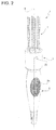
figure 1 illustrates, in a perspective view, a hand held device produced according to the present invention; -
figure 2 illustrates the hand held device offigure 1 with a part removed to illustrate the internal parts; -
figure 3 illustrates in a perspective view and partially in section a portion of the hand held device offigures 1 and2 ; -
figure 4 illustrates the hand held device in a first operating position; -
figure 5 illustrates the hand held device in a second operating position; and -
figure 6 illustrates, in an exploded perspective view, a detail of the hand held device illustrated infigures 1 ,4 and 5 . - In
figures 1 ,2 ,4 and 5 , the reference number 1 indicates, as a whole, a hand held adjustable device comprising anelongated grip 2 provided with a cylindrical end portion 5 (seefigure 2 ) coaxial with an axis 6, and a plurality of rectilinear needles 7 (figures 2 ,4 and 5 ) which extend along the axis 6 from the cylindrical end portion 5 and are made of an electrically conductive material like steel. In the example illustrated all theneedles 7 have the same length, for example 30 or 40 millimetres. The needles can have a different section, for example circular or hexagonal. A portion ofneedles 7 could be covered by an insulating sheath (not illustrated). Thegrip 2 is made of insulating material (for example plastic) and is provided with a plurality ofnon-slip ribs 2n. - According to the present invention, a
device 10 is provided for adjusting the insertion depth of theneedles 7 comprising a cup-shaped body 12 borne by the cylindrical end portion 5 and provided with aflat end wall 13 transversal to the axis 6 and having holes 14 (figure 1 ) for the passage of theneedles 7. Thedevice 10 comprises a system for adjusting the relative position between the cup-shaped body 12 and the end portion 5 suitable for providing an axial sliding of the cup-shaped body 12 with respect to the end portion 5 and adjusting the length of the portion of theneedles 7 which protrudes from theflat end wall 13. - The cup-
shaped body 12 comprises a cylindricaltubular side wall 16 positioned coaxial to the axis 6 and theend wall 13 which has a flat circular form and is transversal to the cylindricaltubular side wall 16 and to the axis 6. The cup-shaped body 12 is made of clear insulating plastic. - Advantageously, the
end wall 13 is defined by a plug element which can rotate with respect to thecylindrical side wall 16 to allow rotation of thewall 16 of the cup-shaped body 12 with respect to theneedles 7 which are fixed. More specifically, the plug element - also having a cup-shaped form - comprises the flatcircular wall 13 which is integral with a cylindricaltubular edge 15; the latter is snap-fitted, by the interposition of a ring-shaped gasket 17 which allows an angular movement, on an end edge 16f (figure 3 ) of thetubular wall 16. - The
position adjustment device 10 comprises a rectilinear groove 20 (figure 3 ) which extends in an axial direction along theside wall 16, and a cylindrical stop element 22 (figure 2 ) which extends in a radial direction from a side wall of the end portion 5 engaging the groove 20 (the diameter of thestop element 22 is substantially equal to the width of the groove 20). Thegroove 20 communicates with a plurality of short rectilineartransversal seats 24 perpendicular to thegroove 20 and equi-spaced from one another along thegroove 20. In this way thegroove 20 and the seats 24 (which have the same length) have the shape of a double comb (figure 3 ) when seen from the side. When thestop element 22 is housed in a seat 24 (figure 3 ), an axially fixed position is achieved between the cup-shaped body 12 and the cylindrical portion 5 since thestop element 20 abuts against opposite portions of theseat 24 preventing sliding of the cup-shaped body 12. When thestop element 22 is housed in thegroove 20, an axially adjustable position is obtained between the cup-shaped body 12 and the cylindrical portion 5 since thestop element 22 can slide in thegroove 20. The passage from the axially fixed position to the axially adjustable position and vice versa is obtained by rotating (see arrow infigure 4 ) the cup-shaped body 12 with respect to the cylindrical portion 5. - By arranging the
stop element 22 indifferent seats 24,a plurality of stable axial positions are obtained between the cup-shaped body 12 and the end portion 5. - In use, the hand held device allows treatment to be performed (for example electroporation treatment) in two ways:
- i) The cup-
shaped body 12 is made to rotate and slide axially so that thecylindrical stop element 22 is positioned in a selected seat 24 - in this way the insertion depth of theneedles 7 in the tissue is adjusted by adjusting the length of the portion ofneedles 7 which protrudes from thewall 13. Thefigures 4 and 5 illustrate two different arrangements of the cup-shaped body corresponding to two different lengths of the portion ofneedles 7 protruding from thewall 13. The selection system is a simple roto-translation (see arrow infigure 4 ) of the cup-shaped body 12 until it reaches theseat 24. The movement allows step selection (for example of 5 mm). - ii) The cylindrical stop is positioned in the
groove 20 so that the cup-shaped body 12 can slide with respect to the cylindrical portion 5 - in this way, the operator can "push" theneedles 7 to the required depth inside the tissue, while guiding them. This characteristic allows problems of misalignment of theneedles 7 from the axis 6 to be considerably reduced.
Claims (6)
- A hand held adjustable device comprising:- a grip (2) provided with an end portion (5);- a plurality of needles (7) which extend axially from the end portion (5) and are made of electrically conducting material,- means (10) for adjusting the depth of introduction of the needles in a tissue are provided, comprising a cup-shaped body (12) borne by said end portion (5) of the grip and provided with an end wall (13) provided with holes (14) for the passage of said needles (7);a system for adjusting the relative position between said cup-shaped body (12) and the end portion (5) adapted to provide an axial sliding of the cup-shaped body (12) with respect to the end portion (5) and adjust the length of the portion of the needles (7) that projects from said end wall (13),
said means for adjusting the relative position are configured to allow for a plurality of stable axial positions between said cup-shaped body and said end portion; the device being characterized in that said means for adjusting the relative position comprise a groove (20) which extends axially along a side wall (16) of said cup-shaped body (12) and a stop element (22) that extends radially from said end portion (5) of the grip and engages said groove (20); said groove (20) communicating with a plurality of transversal seats (24) spaced along the groove itself and used for housing said stop element (22) and for defining respective stable axial positions. - The hand held adjustable device according to claim 1, wherein said cup-shaped body (12) is made of a transparent material.
- The hand held adjustable device according to claim 1 or 2, wherein said cup-shaped body (12) comprises a cylindrical tubular side wall (16) and said end wall (13) transversal to said cylindrical tubular side wall.
- The hand held adjustable device according to claim 3, wherein said end wall (13) is defined. by a plug element that can rotate with respect to the cylindrical tubular side wall (16).
- The hand held adjustable device according to claim 3, wherein said plug element comprises said circular flat end wall (13) which is integral with a cylindrical tubular edge (15) which can be snap-fitted with the possibility of moving angularly, by the interposition of a gasket (17) on an end edge (16f) of said tubular wall (16).
- The hand held adjustable device according to any of the preceding claims, wherein said grip houses a plurality of electrical conductors for connecting said needles to a source of pulses, for example an electroporation apparatus.
Priority Applications (1)
| Application Number | Priority Date | Filing Date | Title |
|---|---|---|---|
| SI201230693A SI2693959T1 (en) | 2011-04-05 | 2012-04-05 | Hand held adjustable device |
Applications Claiming Priority (2)
| Application Number | Priority Date | Filing Date | Title |
|---|---|---|---|
| IT000309A ITTO20110309A1 (en) | 2011-04-05 | 2011-04-05 | ADJUSTABLE HANDPIECE |
| PCT/IB2012/051712 WO2012137176A1 (en) | 2011-04-05 | 2012-04-05 | Hand held adjustable device |
Publications (2)
| Publication Number | Publication Date |
|---|---|
| EP2693959A1 EP2693959A1 (en) | 2014-02-12 |
| EP2693959B1 true EP2693959B1 (en) | 2016-06-01 |
Family
ID=44120434
Family Applications (1)
| Application Number | Title | Priority Date | Filing Date |
|---|---|---|---|
| EP12722521.7A Active EP2693959B1 (en) | 2011-04-05 | 2012-04-05 | Hand held adjustable device |
Country Status (9)
| Country | Link |
|---|---|
| US (1) | US9168367B2 (en) |
| EP (1) | EP2693959B1 (en) |
| DK (1) | DK2693959T3 (en) |
| ES (1) | ES2587237T3 (en) |
| IT (1) | ITTO20110309A1 (en) |
| PL (1) | PL2693959T3 (en) |
| PT (1) | PT2693959T (en) |
| SI (1) | SI2693959T1 (en) |
| WO (1) | WO2012137176A1 (en) |
Families Citing this family (4)
| Publication number | Priority date | Publication date | Assignee | Title |
|---|---|---|---|---|
| US20180161091A9 (en) * | 2014-10-21 | 2018-06-14 | Wendy Epstein | Radio frequency handpiece for medical treatments |
| JP6292705B2 (en) | 2016-02-22 | 2018-03-14 | 公益財団法人東京都医学総合研究所 | Electroporation electrode |
| EP3501595B1 (en) * | 2017-12-22 | 2020-07-29 | IGEA S.p.A. | Handpiece having of expandable electrodes used for electroporation |
| CN120131184A (en) * | 2025-02-13 | 2025-06-13 | 武汉半边天医疗技术发展有限公司 | A four-needle ablation electrode with adjustable needle length |
Family Cites Families (9)
| Publication number | Priority date | Publication date | Assignee | Title |
|---|---|---|---|---|
| US5599300A (en) * | 1992-05-11 | 1997-02-04 | Arrow Precision Products, Inc. | Method for electrosurgically obtaining access to the biliary tree with an adjustably positionable needle-knife |
| US6530922B2 (en) * | 1993-12-15 | 2003-03-11 | Sherwood Services Ag | Cluster ablation electrode system |
| US5873877A (en) * | 1997-04-11 | 1999-02-23 | Vidamed, Inc. | Medical probe device with transparent distal extremity |
| US20050267552A1 (en) * | 2004-05-26 | 2005-12-01 | Baylis Medical Company Inc. | Electrosurgical device |
| US20080200864A1 (en) * | 2005-12-02 | 2008-08-21 | Cabochon Aesthetics, Inc. | Devices and methods for selectively lysing cells |
| GB0604471D0 (en) * | 2006-03-06 | 2006-04-12 | Emcision Ltd | Device and method for the treatment of tumours |
| DK2032057T3 (en) * | 2006-06-12 | 2010-02-08 | Region Hovedstaden V Herlev Ho | Electrode insertion device |
| US20080281389A1 (en) * | 2006-10-16 | 2008-11-13 | Primaeva Medical Inc. | Methods and devices for treating tissue |
| US20100298825A1 (en) | 2009-05-08 | 2010-11-25 | Cellutions, Inc. | Treatment System With A Pulse Forming Network For Achieving Plasma In Tissue |
-
2011
- 2011-04-05 IT IT000309A patent/ITTO20110309A1/en unknown
-
2012
- 2012-04-05 ES ES12722521.7T patent/ES2587237T3/en active Active
- 2012-04-05 EP EP12722521.7A patent/EP2693959B1/en active Active
- 2012-04-05 WO PCT/IB2012/051712 patent/WO2012137176A1/en not_active Ceased
- 2012-04-05 SI SI201230693A patent/SI2693959T1/en unknown
- 2012-04-05 DK DK12722521.7T patent/DK2693959T3/en active
- 2012-04-05 PT PT127225217T patent/PT2693959T/en unknown
- 2012-04-05 US US14/110,135 patent/US9168367B2/en active Active
- 2012-04-05 PL PL12722521.7T patent/PL2693959T3/en unknown
Also Published As
| Publication number | Publication date |
|---|---|
| PL2693959T3 (en) | 2016-12-30 |
| EP2693959A1 (en) | 2014-02-12 |
| PT2693959T (en) | 2016-09-05 |
| US9168367B2 (en) | 2015-10-27 |
| ITTO20110309A1 (en) | 2012-10-06 |
| WO2012137176A1 (en) | 2012-10-11 |
| SI2693959T1 (en) | 2016-12-30 |
| ES2587237T3 (en) | 2016-10-21 |
| US20140148884A1 (en) | 2014-05-29 |
| DK2693959T3 (en) | 2016-09-05 |
Similar Documents
| Publication | Publication Date | Title |
|---|---|---|
| US9168367B2 (en) | Hand held adjustable device | |
| KR102427916B1 (en) | Introduction device comprising an electroactive tip on a guidewire | |
| EP2401976B1 (en) | Treatment device for endoscope | |
| JP2015165927A5 (en) | ||
| WO2009010799A3 (en) | Electric motor/generator assembly | |
| EP2520457A3 (en) | Power feeding control device | |
| WO2006127730A3 (en) | Apparatus and system to stimulate a nerve | |
| WO2015009617A3 (en) | Apparatus and method for securing a plasma torch electrode | |
| JP2007215896A (en) | Bipolar high-frequency treatment instrument for endoscope | |
| EP3513741A3 (en) | Conductor arrangements for electrically powered surgical instruments with rotatable end effectors | |
| US20190001395A1 (en) | Device for producing reinforcement cages | |
| EP3993172A4 (en) | Electrical connection plug, electrical connection device and electric vehicle | |
| WO2013103579A3 (en) | Neural stimulation device with insulating sheath | |
| RU2013101995A (en) | DEVICE FOR REMOVING MATERIAL AND METHOD OF APPLICATION | |
| EP4233755A3 (en) | Device for treating nasal airways | |
| EP1958583A3 (en) | Vessel sealing instrument with electrical cutting mechanism | |
| WO2017067910A3 (en) | Electrosurgical instrument | |
| ATE528829T1 (en) | SOCKET ELEMENT AND CONNECTOR THEREFROM | |
| KR101364445B1 (en) | High frequency beauty equipment | |
| KR20160132770A (en) | Electrosurgical instrument and device with such an instrument | |
| WO2014018252A3 (en) | Temporary implantable lead with electrodes formed by exposed filar portions | |
| US20170224278A1 (en) | Sensor device or eeg electrode and cap having a plurality of sensor devices | |
| CN111029873B (en) | conductive bearing | |
| CN111092347B (en) | Conductive rotating ball | |
| JP2014514440A5 (en) |
Legal Events
| Date | Code | Title | Description |
|---|---|---|---|
| PUAI | Public reference made under article 153(3) epc to a published international application that has entered the european phase |
Free format text: ORIGINAL CODE: 0009012 |
|
| 17P | Request for examination filed |
Effective date: 20131008 |
|
| AK | Designated contracting states |
Kind code of ref document: A1 Designated state(s): AL AT BE BG CH CY CZ DE DK EE ES FI FR GB GR HR HU IE IS IT LI LT LU LV MC MK MT NL NO PL PT RO RS SE SI SK SM TR |
|
| DAX | Request for extension of the european patent (deleted) | ||
| REG | Reference to a national code |
Ref country code: DE Ref legal event code: R079 Ref document number: 602012019182 Country of ref document: DE Free format text: PREVIOUS MAIN CLASS: A61B0017340000 Ipc: A61N0001040000 |
|
| RIC1 | Information provided on ipc code assigned before grant |
Ipc: A61N 1/32 20060101ALI20150914BHEP Ipc: A61B 18/14 20060101ALI20150914BHEP Ipc: A61N 1/04 20060101AFI20150914BHEP |
|
| GRAP | Despatch of communication of intention to grant a patent |
Free format text: ORIGINAL CODE: EPIDOSNIGR1 |
|
| INTG | Intention to grant announced |
Effective date: 20151117 |
|
| RIN1 | Information on inventor provided before grant (corrected) |
Inventor name: CADOSSI, RUGGERO Inventor name: BERTACCHINI, CLAUDIO Inventor name: MARAZZI, DONATA Inventor name: PERAZZOLO GALLO, GIACOMO |
|
| GRAS | Grant fee paid |
Free format text: ORIGINAL CODE: EPIDOSNIGR3 |
|
| GRAA | (expected) grant |
Free format text: ORIGINAL CODE: 0009210 |
|
| AK | Designated contracting states |
Kind code of ref document: B1 Designated state(s): AL AT BE BG CH CY CZ DE DK EE ES FI FR GB GR HR HU IE IS IT LI LT LU LV MC MK MT NL NO PL PT RO RS SE SI SK SM TR |
|
| REG | Reference to a national code |
Ref country code: GB Ref legal event code: FG4D |
|
| REG | Reference to a national code |
Ref country code: CH Ref legal event code: EP Ref country code: AT Ref legal event code: REF Ref document number: 803495 Country of ref document: AT Kind code of ref document: T Effective date: 20160615 |
|
| REG | Reference to a national code |
Ref country code: IE Ref legal event code: FG4D |
|
| REG | Reference to a national code |
Ref country code: DE Ref legal event code: R096 Ref document number: 602012019182 Country of ref document: DE |
|
| REG | Reference to a national code |
Ref country code: NL Ref legal event code: FP |
|
| REG | Reference to a national code |
Ref country code: DK Ref legal event code: T3 Effective date: 20160901 Ref country code: PT Ref legal event code: SC4A Ref document number: 2693959 Country of ref document: PT Date of ref document: 20160905 Kind code of ref document: T Free format text: AVAILABILITY OF NATIONAL TRANSLATION Effective date: 20160830 |
|
| REG | Reference to a national code |
Ref country code: SE Ref legal event code: TRGR |
|
| REG | Reference to a national code |
Ref country code: LT Ref legal event code: MG4D |
|
| REG | Reference to a national code |
Ref country code: CH Ref legal event code: NV Representative=s name: HEPP WENGER RYFFEL AG, CH |
|
| REG | Reference to a national code |
Ref country code: ES Ref legal event code: FG2A Ref document number: 2587237 Country of ref document: ES Kind code of ref document: T3 Effective date: 20161021 |
|
| PG25 | Lapsed in a contracting state [announced via postgrant information from national office to epo] |
Ref country code: LT Free format text: LAPSE BECAUSE OF FAILURE TO SUBMIT A TRANSLATION OF THE DESCRIPTION OR TO PAY THE FEE WITHIN THE PRESCRIBED TIME-LIMIT Effective date: 20160601 |
|
| REG | Reference to a national code |
Ref country code: NO Ref legal event code: T2 Effective date: 20160601 |
|
| PG25 | Lapsed in a contracting state [announced via postgrant information from national office to epo] |
Ref country code: RS Free format text: LAPSE BECAUSE OF FAILURE TO SUBMIT A TRANSLATION OF THE DESCRIPTION OR TO PAY THE FEE WITHIN THE PRESCRIBED TIME-LIMIT Effective date: 20160601 Ref country code: GR Free format text: LAPSE BECAUSE OF FAILURE TO SUBMIT A TRANSLATION OF THE DESCRIPTION OR TO PAY THE FEE WITHIN THE PRESCRIBED TIME-LIMIT Effective date: 20160902 Ref country code: LV Free format text: LAPSE BECAUSE OF FAILURE TO SUBMIT A TRANSLATION OF THE DESCRIPTION OR TO PAY THE FEE WITHIN THE PRESCRIBED TIME-LIMIT Effective date: 20160601 Ref country code: HR Free format text: LAPSE BECAUSE OF FAILURE TO SUBMIT A TRANSLATION OF THE DESCRIPTION OR TO PAY THE FEE WITHIN THE PRESCRIBED TIME-LIMIT Effective date: 20160601 |
|
| PG25 | Lapsed in a contracting state [announced via postgrant information from national office to epo] |
Ref country code: CZ Free format text: LAPSE BECAUSE OF FAILURE TO SUBMIT A TRANSLATION OF THE DESCRIPTION OR TO PAY THE FEE WITHIN THE PRESCRIBED TIME-LIMIT Effective date: 20160601 Ref country code: EE Free format text: LAPSE BECAUSE OF FAILURE TO SUBMIT A TRANSLATION OF THE DESCRIPTION OR TO PAY THE FEE WITHIN THE PRESCRIBED TIME-LIMIT Effective date: 20160601 Ref country code: SK Free format text: LAPSE BECAUSE OF FAILURE TO SUBMIT A TRANSLATION OF THE DESCRIPTION OR TO PAY THE FEE WITHIN THE PRESCRIBED TIME-LIMIT Effective date: 20160601 Ref country code: RO Free format text: LAPSE BECAUSE OF FAILURE TO SUBMIT A TRANSLATION OF THE DESCRIPTION OR TO PAY THE FEE WITHIN THE PRESCRIBED TIME-LIMIT Effective date: 20160601 Ref country code: IS Free format text: LAPSE BECAUSE OF FAILURE TO SUBMIT A TRANSLATION OF THE DESCRIPTION OR TO PAY THE FEE WITHIN THE PRESCRIBED TIME-LIMIT Effective date: 20161001 |
|
| PG25 | Lapsed in a contracting state [announced via postgrant information from national office to epo] |
Ref country code: SM Free format text: LAPSE BECAUSE OF FAILURE TO SUBMIT A TRANSLATION OF THE DESCRIPTION OR TO PAY THE FEE WITHIN THE PRESCRIBED TIME-LIMIT Effective date: 20160601 |
|
| REG | Reference to a national code |
Ref country code: DE Ref legal event code: R097 Ref document number: 602012019182 Country of ref document: DE |
|
| REG | Reference to a national code |
Ref country code: FR Ref legal event code: PLFP Year of fee payment: 6 |
|
| PLBE | No opposition filed within time limit |
Free format text: ORIGINAL CODE: 0009261 |
|
| STAA | Information on the status of an ep patent application or granted ep patent |
Free format text: STATUS: NO OPPOSITION FILED WITHIN TIME LIMIT |
|
| 26N | No opposition filed |
Effective date: 20170302 |
|
| PG25 | Lapsed in a contracting state [announced via postgrant information from national office to epo] |
Ref country code: MC Free format text: LAPSE BECAUSE OF FAILURE TO SUBMIT A TRANSLATION OF THE DESCRIPTION OR TO PAY THE FEE WITHIN THE PRESCRIBED TIME-LIMIT Effective date: 20160601 |
|
| REG | Reference to a national code |
Ref country code: FR Ref legal event code: PLFP Year of fee payment: 7 |
|
| PG25 | Lapsed in a contracting state [announced via postgrant information from national office to epo] |
Ref country code: MT Free format text: LAPSE BECAUSE OF NON-PAYMENT OF DUE FEES Effective date: 20170405 |
|
| PG25 | Lapsed in a contracting state [announced via postgrant information from national office to epo] |
Ref country code: AL Free format text: LAPSE BECAUSE OF FAILURE TO SUBMIT A TRANSLATION OF THE DESCRIPTION OR TO PAY THE FEE WITHIN THE PRESCRIBED TIME-LIMIT Effective date: 20160601 |
|
| REG | Reference to a national code |
Ref country code: AT Ref legal event code: UEP Ref document number: 803495 Country of ref document: AT Kind code of ref document: T Effective date: 20160601 |
|
| PG25 | Lapsed in a contracting state [announced via postgrant information from national office to epo] |
Ref country code: HU Free format text: LAPSE BECAUSE OF FAILURE TO SUBMIT A TRANSLATION OF THE DESCRIPTION OR TO PAY THE FEE WITHIN THE PRESCRIBED TIME-LIMIT; INVALID AB INITIO Effective date: 20120405 |
|
| PG25 | Lapsed in a contracting state [announced via postgrant information from national office to epo] |
Ref country code: BG Free format text: LAPSE BECAUSE OF FAILURE TO SUBMIT A TRANSLATION OF THE DESCRIPTION OR TO PAY THE FEE WITHIN THE PRESCRIBED TIME-LIMIT Effective date: 20160601 |
|
| PG25 | Lapsed in a contracting state [announced via postgrant information from national office to epo] |
Ref country code: CY Free format text: LAPSE BECAUSE OF NON-PAYMENT OF DUE FEES Effective date: 20160601 |
|
| PG25 | Lapsed in a contracting state [announced via postgrant information from national office to epo] |
Ref country code: MK Free format text: LAPSE BECAUSE OF FAILURE TO SUBMIT A TRANSLATION OF THE DESCRIPTION OR TO PAY THE FEE WITHIN THE PRESCRIBED TIME-LIMIT Effective date: 20160601 |
|
| PG25 | Lapsed in a contracting state [announced via postgrant information from national office to epo] |
Ref country code: TR Free format text: LAPSE BECAUSE OF FAILURE TO SUBMIT A TRANSLATION OF THE DESCRIPTION OR TO PAY THE FEE WITHIN THE PRESCRIBED TIME-LIMIT Effective date: 20160601 |
|
| P01 | Opt-out of the competence of the unified patent court (upc) registered |
Effective date: 20230629 |
|
| PGFP | Annual fee paid to national office [announced via postgrant information from national office to epo] |
Ref country code: DE Payment date: 20250319 Year of fee payment: 14 |
|
| PGFP | Annual fee paid to national office [announced via postgrant information from national office to epo] |
Ref country code: ES Payment date: 20250502 Year of fee payment: 14 |
|
| PGFP | Annual fee paid to national office [announced via postgrant information from national office to epo] |
Ref country code: CH Payment date: 20250501 Year of fee payment: 14 |
|
| PGFP | Annual fee paid to national office [announced via postgrant information from national office to epo] |
Ref country code: AT Payment date: 20250321 Year of fee payment: 14 |
|
| PGFP | Annual fee paid to national office [announced via postgrant information from national office to epo] |
Ref country code: SE Payment date: 20260319 Year of fee payment: 15 |
|
| PGFP | Annual fee paid to national office [announced via postgrant information from national office to epo] |
Ref country code: GB Payment date: 20260319 Year of fee payment: 15 |
|
| PGFP | Annual fee paid to national office [announced via postgrant information from national office to epo] |
Ref country code: NO Payment date: 20260320 Year of fee payment: 15 Ref country code: DK Payment date: 20260319 Year of fee payment: 15 Ref country code: IE Payment date: 20260320 Year of fee payment: 15 |
|
| PGFP | Annual fee paid to national office [announced via postgrant information from national office to epo] |
Ref country code: FI Payment date: 20260319 Year of fee payment: 15 Ref country code: LU Payment date: 20260319 Year of fee payment: 15 Ref country code: BE Payment date: 20260319 Year of fee payment: 15 Ref country code: IT Payment date: 20260319 Year of fee payment: 15 |
|
| PGFP | Annual fee paid to national office [announced via postgrant information from national office to epo] |
Ref country code: NL Payment date: 20260319 Year of fee payment: 15 |
|
| PGFP | Annual fee paid to national office [announced via postgrant information from national office to epo] |
Ref country code: FR Payment date: 20260320 Year of fee payment: 15 |
|
| PGFP | Annual fee paid to national office [announced via postgrant information from national office to epo] |
Ref country code: PT Payment date: 20260320 Year of fee payment: 15 |
|
| PGFP | Annual fee paid to national office [announced via postgrant information from national office to epo] |
Ref country code: PL Payment date: 20260325 Year of fee payment: 15 |
|
| PGFP | Annual fee paid to national office [announced via postgrant information from national office to epo] |
Ref country code: SI Payment date: 20260325 Year of fee payment: 15 |
|
| REG | Reference to a national code |
Ref country code: CH Ref legal event code: U11 Free format text: ST27 STATUS EVENT CODE: U-0-0-U10-U11 (AS PROVIDED BY THE NATIONAL OFFICE) Effective date: 20260501 |